

Page 1

Wireless Modem Assembly
Part Number 1815-740
IMPORTANT!
Wireless modems are configured for DoorKing systems. Do not change the switches on the
modems. Doing so will change their programming and the modems will not function with DoorKing
products.
Parts List for P/N 1815-740
1. P/N 1815-726 - RF Modem USB Configured includes:
• Quick Start Guide
• X-CTU software CD
• Antenna 1/2 Wave Dipole
• USB Cable, 6-Ft.
• Power adapter, 9V 1A
2. P/N 1815-725 - RF Modem RS 232 Configured includes:
• Antenna 1/2 Wave Dipole
• Serial Loop Back Adapter
• Null Modem Adapter
• Power adapter, 9V 1A
3. P/N 1818-040 - RS 232 Cable 6-Ft.
4. P/N 1815-721 – CD MaxStream 2060 Files
5. P/N 1815-760 – Manual
Notes:
• You must install USB driver on your PC using the X-CTU CD.
• The X-CTU software, the MaxStream CD and the RED serial loop back adapter are
used for trouble shooting only.
• You may cut and splice the wires for the power adapters if necessary. However,
you must observe the polarity! I.E., striped wire to striped wire. Permanent
damage will occur to the modem if polarity is incorrect! For wire runs up to 100
feet, use 22 AWG wire. For wire runs up to 200 feet, use 18 AWG wire.
• If installed outdoors, the modem and power supply must be installed in a rain-tight
enclosure.
P/N 1815-760 REV A 10/07 Page 1
Page 2
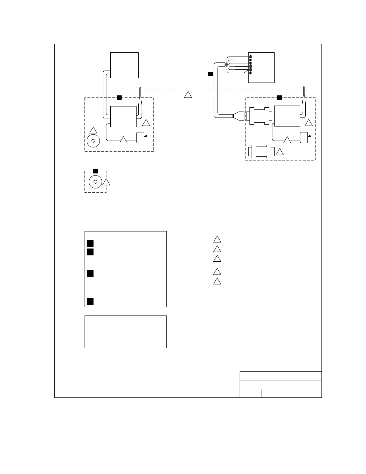
USB Port
PC
Line-of-Site Wireless
5
Red
1
Black
White
Brown
Green
A
Shield
RS232
2
Terminals
3
4
5
6
1833, 1834
1835, 1837
1838
BC
RF MODEM
USB Configured
1
X-CTU
Software
4
D
MaxStream
2
2060 Files
Wireless Modem Assembly P/N 1815- 740
RS232 Cable P/N 1818-040
A
RF Modem Ass’y RS 232 Configured P/N 1815-725
B
Dipole Antenna
Serial Loop Back Adapter
Null Modem Adapter
Power Supply 9V 1A
RF Modem Ass’y USB Configured P/N 1815-726
C
Dipole Antenna
USB Cable
Power Supply 9V 1A
X-CTU Software CD
Quick Start Guide
Null
Modem
Serial Loop
Back Adapter
You must install the USB driver on your PC using the X-CTU CD
1
Used for trouble shooting only
2
Power wires may be cut and spliced if necessary. Observe Polarity!
3
I.E. striped wire to striped wire. Permanent damage will occur if
polarity is not observed!
If mounted outdoors, must be in rain tight enclosure.
4
Use high-gain antenna kit (P/N 1815-741) for distances greater than
5
500 feet.
RF MODEM
RS-232
Configured
33
2
4
CD MaxStream 2060 Files P/N 1815-721
D
Notes
≅ This assembly will only work with the Remote Account
Manager Software version 6.0 or later.
≅ 1833, 1834, 1835 and 1837 circuit boards must be
REV I or higher.
≅ 1838 circuit board must be REV H or higher.
P/N 1815-760 REV A 10/07 Page 2
DOORKING, INC., INGLEWOOD, CA 90301
Wireless Modem Assembly
Title:
Wiring Instructions
10/07
Date: Dwg. No. Rev.
M-1815-760
A
Page 3
Range Consideration
There are a number of factors that can affect the range of the wireless modems, including:
• The environment or space between the modems
• The types of antennas used.
• The mounting of the antennas.
Environment
We found that up to about 500 feet, a visual line-of-sight
worked fine with the standard dipole antennas that come
with the wireless modems. While visual line-of-sight may
be fine for many applications, better range can be
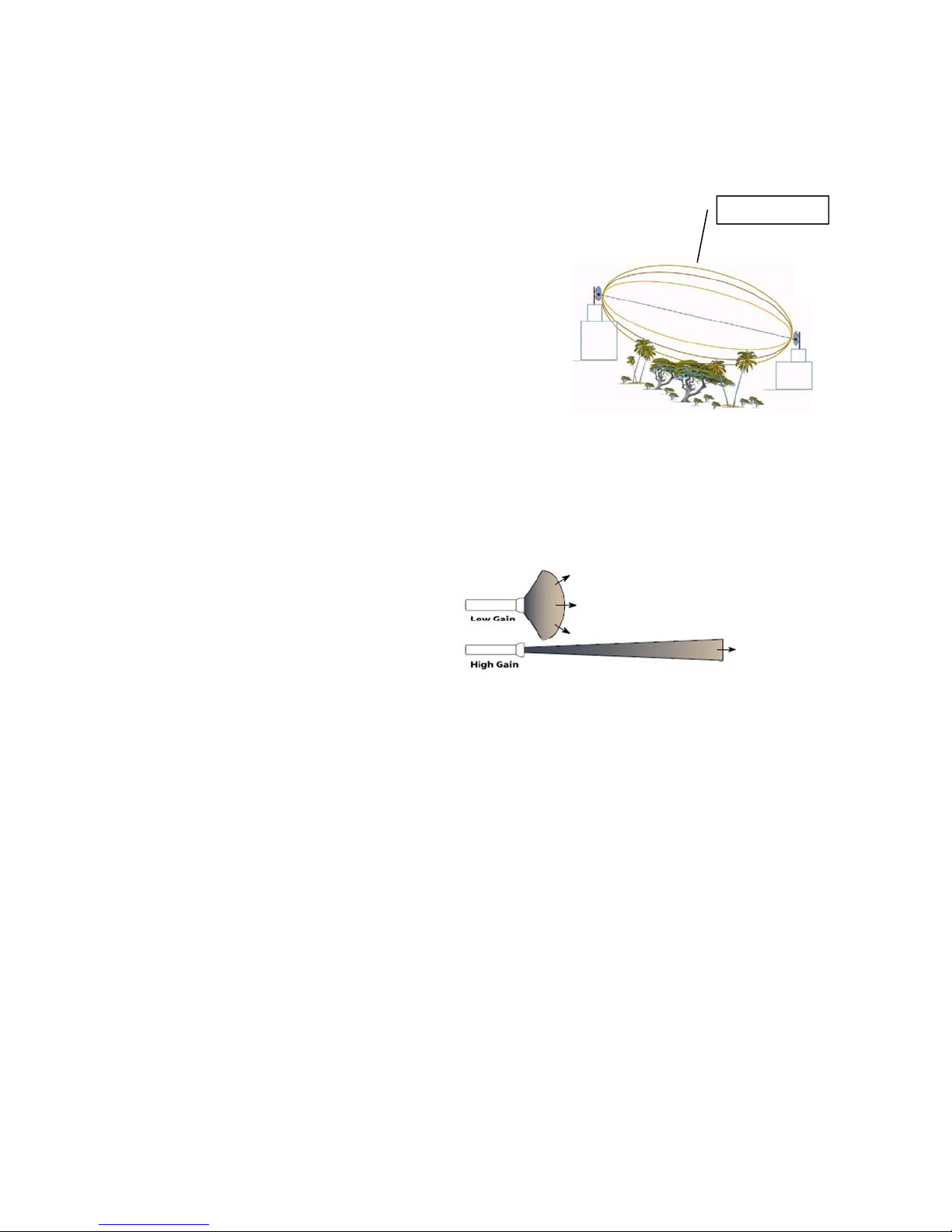
achieved by observing the Fresnel Zone – the football
shaped tunnel between the two sites that provides a path
for RF signals.
If the antennas are mounted just barely off the ground, the earth will obstruct half of the Fresnel zone.
Buildings, trees (that may grow later) or any other obstructions will further decrease the
communication range. For optimum range, set up the antennas to allow a free and clear Fresnel
zone. The diameter of the Fresnel zone is typically 16-feet when the antennas are 1000 feet apart.
Antenna Types
We suggest using high-gain antennas
(DoorKing P/N 1815-741) when a range of
greater than 500 feet is desired. Highgain antennas focus the RF energy if a
particular direction. How much energy is
focused in the particular direction is
referred to as antenna gain. A flashlight
whose beam can be adjusted by twisting
the lens illustrates this.
A low gain antenna cannot receive signals from a long distance, but they can receive signals from a
wider area. High-gain antennas, on the other hand, can receive signals from a longer distance, but
the area they receive them from is smaller.
Use high-gain antennas in applications where longer range and more focused transmissions are
required.
• P/N 1815-741 High-gain Antenna Kit (includes 20-feet coax cable).
Antenna Mounting
When mounting an antenna, care should be taken to make sure it is as far away from metal objects
as possible. If the antenna is mounted too close to nearby metal, the metal has the potential to
interfere with the way the antenna radiates the RF signal and thus decrease the range.
In some cases, a coax cable must be used to connect the antenna to the wireless modem. All coax
cables add losses to the system. For any given cable, the longer the cable, the greater the loss
becomes. Often, a longer serial cable to the DoorKing system or a longer USB cable to the PC can
be used to minimize the length of the coax cable.
Fresnel Zone
P/N 1815-760 REV A 10/07 Page 3
 Loading...