

Page 1
EN
ENERGY & LIGHTING
TEC
Generator
Installation and Operating Manual
TEC29 EV AUS
Page 2

Page 3

EN
TEC29 EV AUS
Please read this instruction manual carefully before installation and first
use, and store it in a safe place. If you pass on the product to another
person, hand over this instruction manual along with it.
Table of contents
1 Explanation of symbols. . . . . . . . . . . . . . . . . . . . . . . . . . . . . . . . . . . . . . . . . . .4
2 Safety instructions . . . . . . . . . . . . . . . . . . . . . . . . . . . . . . . . . . . . . . . . . . . . . . .4
3 Scope of delivery . . . . . . . . . . . . . . . . . . . . . . . . . . . . . . . . . . . . . . . . . . . . . . .7
4 Accessories . . . . . . . . . . . . . . . . . . . . . . . . . . . . . . . . . . . . . . . . . . . . . . . . . . . .8
5 Intended use . . . . . . . . . . . . . . . . . . . . . . . . . . . . . . . . . . . . . . . . . . . . . . . . . . .8
6 Labels. . . . . . . . . . . . . . . . . . . . . . . . . . . . . . . . . . . . . . . . . . . . . . . . . . . . . . . . .8
7 Technical description . . . . . . . . . . . . . . . . . . . . . . . . . . . . . . . . . . . . . . . . . . . .9
8 Installation . . . . . . . . . . . . . . . . . . . . . . . . . . . . . . . . . . . . . . . . . . . . . . . . . . . . 12
9 Connecting the electrical power to the generator . . . . . . . . . . . . . . . . . . . 20
10 Operating the generator . . . . . . . . . . . . . . . . . . . . . . . . . . . . . . . . . . . . . . . 29
11 Cleaning the generator. . . . . . . . . . . . . . . . . . . . . . . . . . . . . . . . . . . . . . . . . 36
12 Servicing the generator . . . . . . . . . . . . . . . . . . . . . . . . . . . . . . . . . . . . . . . . 37
13 Troubleshooting . . . . . . . . . . . . . . . . . . . . . . . . . . . . . . . . . . . . . . . . . . . . . . 43
14 Warranty . . . . . . . . . . . . . . . . . . . . . . . . . . . . . . . . . . . . . . . . . . . . . . . . . . . . 45
15 Disposal . . . . . . . . . . . . . . . . . . . . . . . . . . . . . . . . . . . . . . . . . . . . . . . . . . . . . 45
16 Technical data . . . . . . . . . . . . . . . . . . . . . . . . . . . . . . . . . . . . . . . . . . . . . . . . 46
3
Page 4

EN
Explanation of symbols TEC29 EV AUS
1 Explanation of symbols
WARNING!
!
Safety instruction: Failure to observe this instruction can cause fatal or
serious injury.
CAUTION!
Safety instruction: Failure to observe this instruction can lead to injury.
!
NOTICE!
A
Failure to observe this instruction can cause material damage and impair
the function of the product.
NOTE
Supplementary information for operating the product.
I
2 Safety instructions
The manufacturer accepts no liability for damage in the following cases:
• Damage to the product resulting from mechanical influences and excess voltage
• Alterations to the product without express permission from the manufacturer
• Use for purposes other than those described in the operating manual
In particular, the manufacturer will not be liable for any consequential damage,
especially consequential damage caused by failure of the generator.
Note the following basic safety information when using electrical devices to protect
against:
• Electric shock
• Fire hazards
• Injury
4
Page 5

EN
TEC29 EV AUS Safety instructions
2.1 General safety
WARNING!
!
• Electrical devices are not toys
Keep electrical devices out of reach of children or infirm persons. Do
not allow them to use electrical devices without supervision.
• People (including children) whose physical, sensory or mental
capacities prevent them from using this device safely may not be
allowed to operate it without the supervision of a responsible adult.
• Only use the device as intended.
• Do not make any alterations or conversions to the device.
• Installation, maintenance and repairs of the generator may only be
carried out by qualified personnel who are familiar with the risks
involved when handling generators as well as the relevant regulations.
Inadequate repairs may cause serious hazards. For repair service,
please contact the manufacturer's branch office in your country
(addresses on the back page).
• Exhaust fumes contain carbon monoxide which is a highly toxic,
odourless and colourless gas. Do not inhale any exhaust fumes. Do
not leave the generator motor running in a closed garage or in a room
without windows.
!
CAUTION!
• The generator may only be used with the front door closed.
• Remove all flammable materials such as petrol, paints, solvents, etc.,
from the vicinity of the generator.
• Ensure that hot parts of the generator do not come in contact with any
flammable materials.
• Only refuel the generator when it is switched off and in a well-
ventilated area. Petrol and liquid gas are highly flammable and can
explode.
• Do not refuel the generator when the vehicle engine is running if the
tank is in the vicinity of the generator.
• If petrol is spilled, wipe it up properly and wait until the fumes have
cleared before turning on the engine.
• Do not touch the generator and the cables with wet hands.
• Replace the fuses using only those with the same technical data.
• Do not switch the generator to automatic mode near any ignition
sources (such as petrol stations, dry areas with risk of forest fires).
5
Page 6

EN
Safety instructions TEC29 EV AUS
NOTICE!
A
2.2 Mounting the device
!
• Do not fill up the tank too full. Petrol must not be allowed to fill up to
the neck of the tank. Check the lid is on properly.
CAUTION!
• Fire hazards
Do not install the generator in a box or room without any openings,
but in well-ventilated spaces instead.
• Install the generator on a stable surface.
• Do not tilt the generator more than 20° from the vertical position.
NOTICE!
• The generator is not suitable for use in water vessels.
A
2.3 Handling electrical cables
WARNING!
!
!
• The electrical power supply may only be connected by a qualified
electrician.
CAUTION!
• Attach and lay the cables so that they cannot be tripped over or
damaged. All the wiring must comply to AS3000 and AS3001.
NOTICE!
• Use cable ducts to lay cables through walls with sharp edges.
A
• Do not lay loose or bent cables next to electrically conductive
materials (metal).
• Do not pull on the cables.
2.4 Operating the device safely
WARNING!
• Always disconnect the power supply when working on the device.
!
NOTICE!
A
6
• Only operate the device if you are certain that the housing and the
cables are undamaged.
Page 7
EN
TEC29 EV AUS Scope of delivery
2
1
3
4
9
7
6
8
10 11
12
5
1
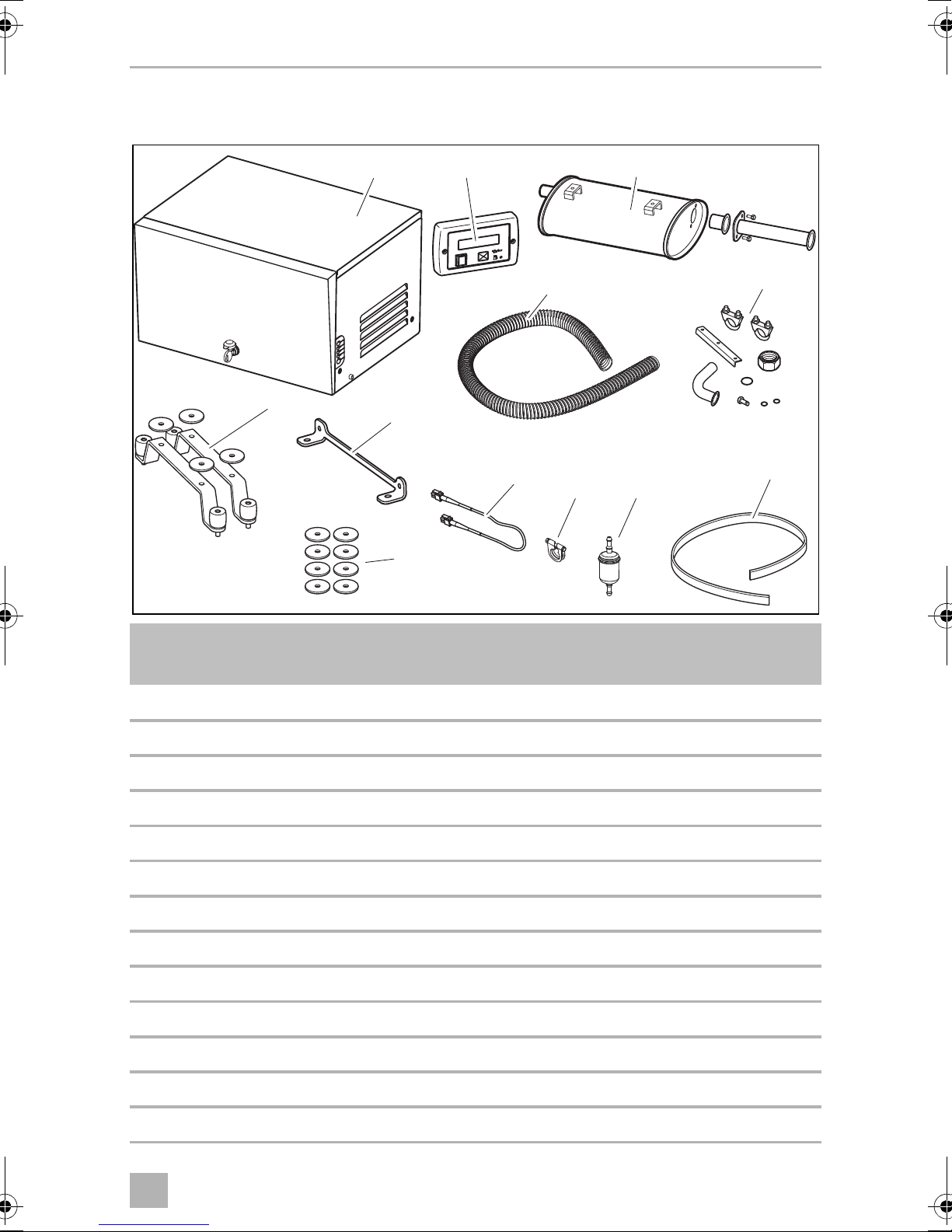
3Scope of delivery
Item in
fig. 1
1 1 Generator
2 1 Digital control panel
3 1 Silencer with spark arrestor and fixing material
4 1 Exhaust hose, 2 m
5 1 set Mounting bracket for silencer
6 1 set Retaining bracket for external installation
7 2 Holder for internal installation
8 8 Washer
9 1 Extension cable for digital control panel, 8 m
10 1 Hose clamp
11 1 Fuel filter
12 1 Seal AG 128
Number Description
– 1 Installation and operating manual
7
Page 8
EN
Accessories TEC29 EV AUS
4Accessories
Available as accessories (not included in the scope of delivery):
Part designation Ref. number
AG 101, tank 15 l, plastic 9102900009
AG 100, tank 20 l, stainless steel 9102900011
AG 150, pipe set for AG 100/AG 101
(1 m fuel hose refuelling, 60 mm,
2 m fuel hose breathing,
2 m fuel hose feeding)
AG 125, flexible metal pipe for extending exhaust pipe, 5 m 9102900138
AG 163, flexible metal pipe fixing kit 9102900028
Parallel cable 9102900296
9102900003
5 Intended use
The TEC29 EV AUS (ref. no. 9102900291) generator is designed for use in motor
homes, camper vans and vehicles for commercial use.
The generator is not suitable for installation in water vessels.
The generator produces a pure sine wave voltage of 230 V/50 Hz which can be
connected to the consumer with a total continuous load of 2600 W. The power
quality is also suitable for sensitive consumers (such as PCs).
The generator can charge a 12 V battery (AGM, Gel, lead acid and Dometic eStore
Li-Ion battery).
6Labels
A label is attached to the generator. This label provides the user and fitter with
information on the device specifications.
8
Page 9
EN
TEC29 EV AUS Technical description
1
5
6
3
4
2
2
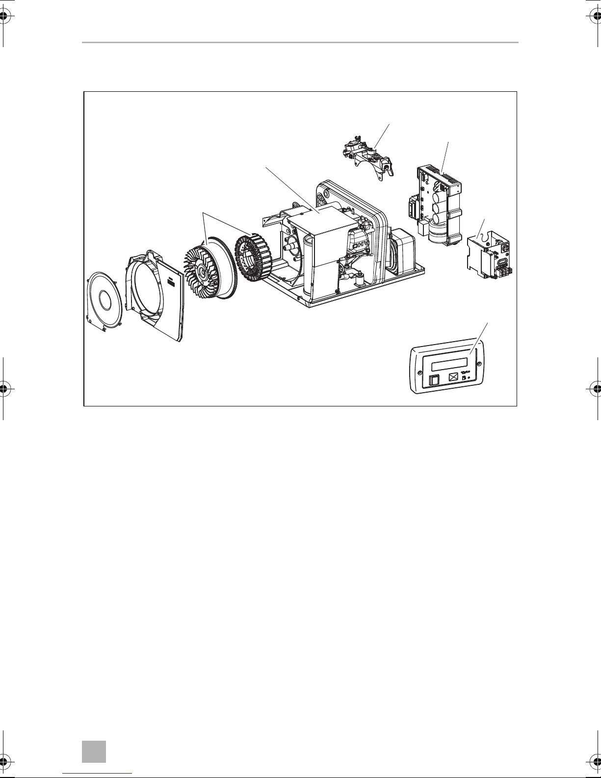
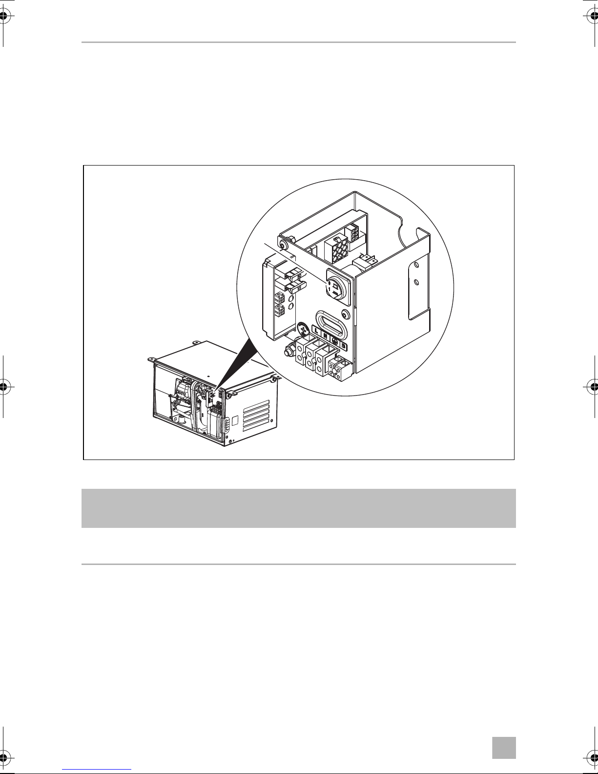
7 Technical description
The TEC29 EV AUS generator consists of the following main parts (fig. 2, page 9):
• Combustion engine (1)
• Alternator (2) with permanent magnets
• Stepper motor (3)
• Inverter (4)
• Internal control panel (5)
• Remote control (6)
The combustion engine (1) drives the alternator (2) connected to it, which in turn
generates AC voltage.
The inverter (4) transforms this AC voltage into a stable voltage of 230 V and 50 Hz.
The terminals, the socket for the connection cable to the digital control panel (6) and
the main switch are installed in the internal control panel (5).
9
Page 10
EN
Technical description TEC29 EV AUS
3
The generator has the following features:
• Automatic mode for charging the connected battery automatically (must be
configured accordingly when installed, see chapter “Configuring the automatic
mode” on page 25)
Control elements in the control panel
1
The control panel is located on the generator behind the cover.
Item in
fig. 3
1 Main switch Switches the generator to standby or no
Description
function.
10
Page 11
EN
TEC29 EV AUS Technical description
5
3
2
1
6
4
7 8
109
4
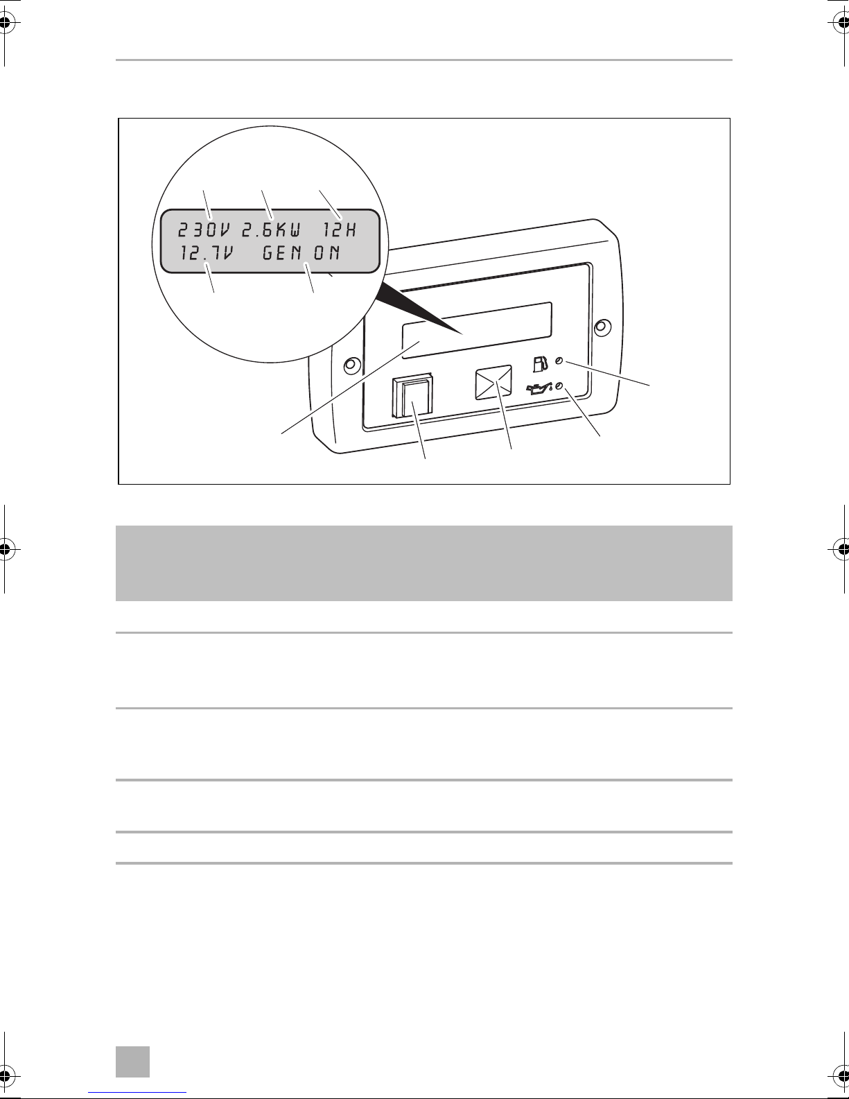
Control elements in the digital control panel
The digital control panel is installed in the vehicle interior.
Item in
fig. 4,
page 11
1 Display Shows the status reports.
2 On/Off switch P Switches the digital control panel on and off if
3 START/STOP button Starts and stops the generator if the digital
4 Oil LED Lights up if the oil level is too low in the
5 Petrol LED Lights up if the petrol goes into reserve.
Description
the main switch is at “I” or “1”.
Stops the generator.
control panel is switched on and the main
switch is at “I” or “1”.
engine.
11
Page 12
EN
Installation TEC29 EV AUS
Displays
Item in
fig. 4,
page 11
6 AC supply Approximate voltage (±5 %)
7 Power output Power draw through connected load
8 Operating hours Time the generator is in operation
9 DC voltage Battery voltage
10 Messages Status reports of the generator (see chapter
Description
“Display messages” on page 32)
8 Installation
CAUTION! Beware of injury
!
8.1 Note on installation
Read the installation manual carefully before you install the generator.
When installing the generator, note the following:
The generator may only be installed by qualified personnel from a
specialist company. The following information is intended for
technicians who are familiar with the guidelines and safety precautions
to be applied.
DANGER! Danger of electrocution
Disconnect all power supplies when working on the generator.
D
CAUTION! Beware of injury
!
• Improper installation of the generator can result in irreparable
damage to the device and put the safety of the user at risk.
• Always wear the recommended protective clothing (e.g. protective
goggles, gloves).
12
Page 13
EN
TEC29 EV AUS Installation
10.5
385
160
99
580
548
480
290
360
1
1
5
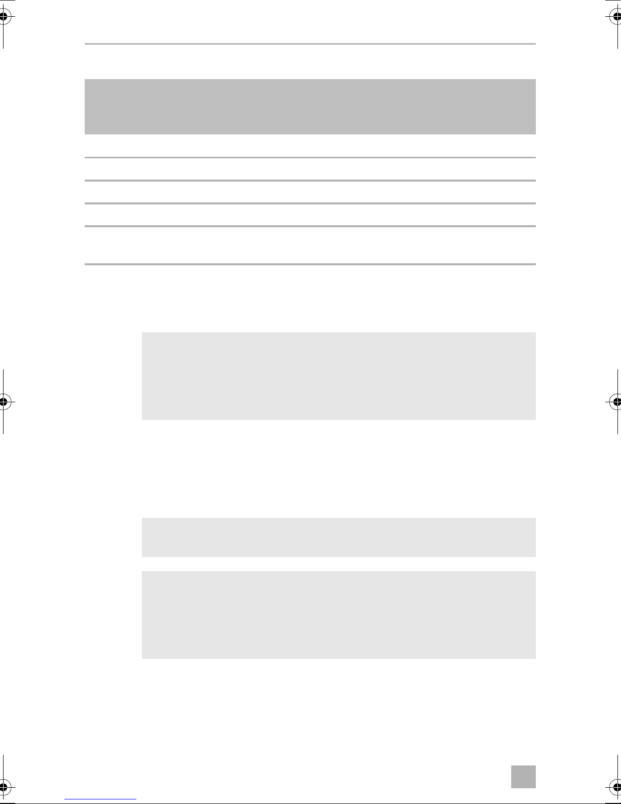
8.2 Securing the generator
Note on installation location
• Make sure that no combustible objects are stored or installed near the air outlet
or the ventilation slots. A distance of at least 50 cm should be kept.
• For safety reasons, note the location of existing wiring harnesses, wires and other
components within the installation area, in particular those which are not visible,
when installing the generator (when drilling or screwing etc.).
You can secure the generator with the holders supplied in two ways:
• External installation (fig. 5):
External installation has the following benefits: lower space requirement, fast
installation, easy access for maintenance work.
– To ensure the generator is attached securely, use the retaining bracket
(fig. 5 1) supplied.
– If the air intake opening of the generator is located behind a vehicle wheel,
you need to prevent the wheel from splashing any water into the generator
interior when it rains (e.g. by using a splash guard).
13
Page 14
EN
Installation TEC29 EV AUS
548
23
20
35
104
310
295
360
30
2
1
6
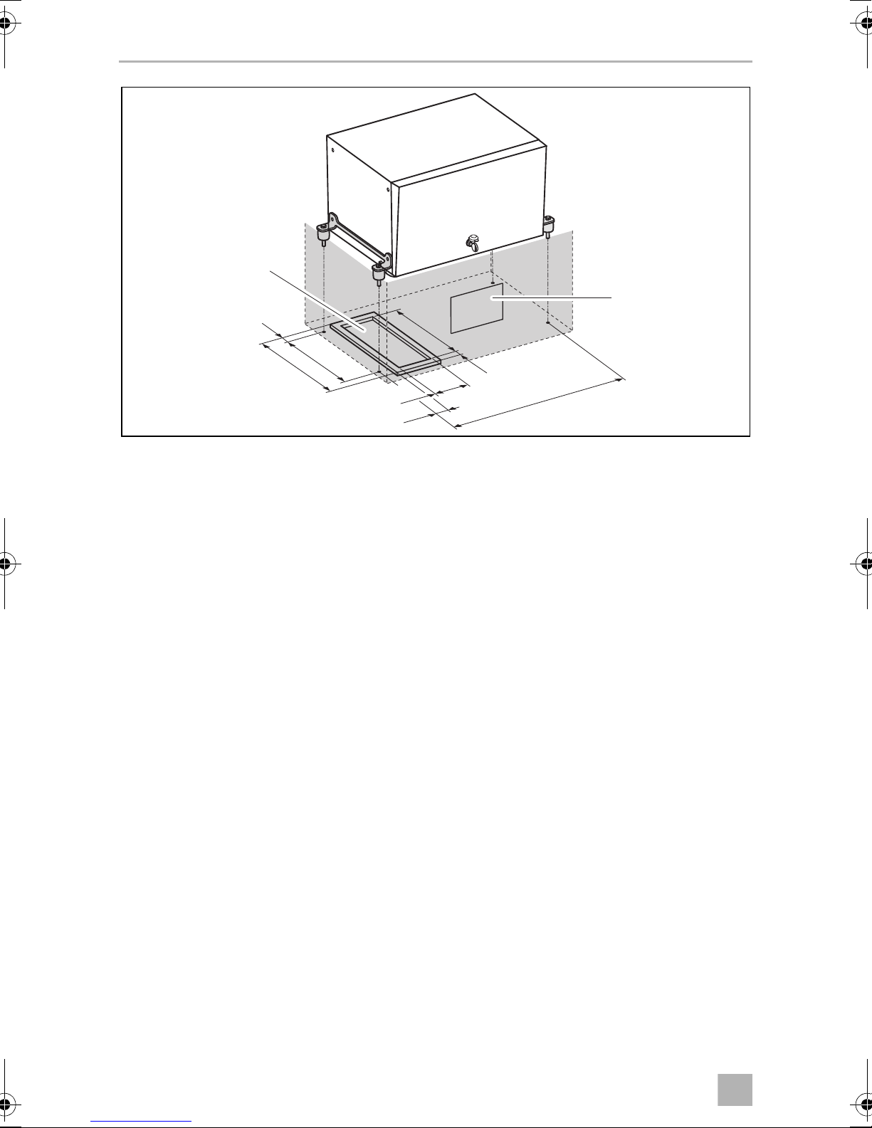
• Internal installation (fig. 6):
For internal installation, you need to prepare a sealed compartment against the
vehicle interior which can also be insulated against sound.
– Attach exhaust and air intake openings to the floor and in front of the
generator cover. The air intake openings must have cross-section of at least
240 cm
2
.
– You must also fit a seal (AG 128; included in the scope of delivery) made of
fire-retardant rubber with a thickness of at least 5 mm between the floor of the
vehicle and the generator.
– Fix the provided 8 washers between the floor and the vibration dampers
(2 pieces each).
• Leave a space of at least 20 mm between the generator hood and surrounding
parts so that sufficient space remains for cooling air to pass through.
14
Page 15
EN
TEC29 EV AUS Installation
1
2 3 4
7
8.3 Securing the silencer
Observe the following instructions when installing the exhaust pipe:
• Do not create any sharp bends which will inhibit the flow of exhaust fumes.
• Align the manifold (fig. 7 1) along the housing to ensure greater damping of
vibration.
• Use the exhaust pipe extension to extent the exhaust pipe (fig. 7 2) (see
chapter “Accessories” on page 8).
Secure the extension to the vehicle floor (fig. 7 3) according to ADR 42.8.
• If cutting the exhaust pipe, wear protective gloves and be careful of sharp edges.
➤ Secure the silencer (fig. 7 4) as in one of the alternatives shown in fig. 8,
page 16 to fig. b, page 17.
Washers, brackets and screws are not included in the scope of delivery.
15
Page 16

EN
Installation TEC29 EV AUS
8
9
0
16
Page 17

EN
TEC29 EV AUS Installation
a
b
➤ Fix the exhaust pipe to the vehicle using flexible elements to reduce vibrations
(e.g AG 163, available as accessory).
17
Page 18

EN
Installation TEC29 EV AUS
max. 2 m
max. 0.3 m
c
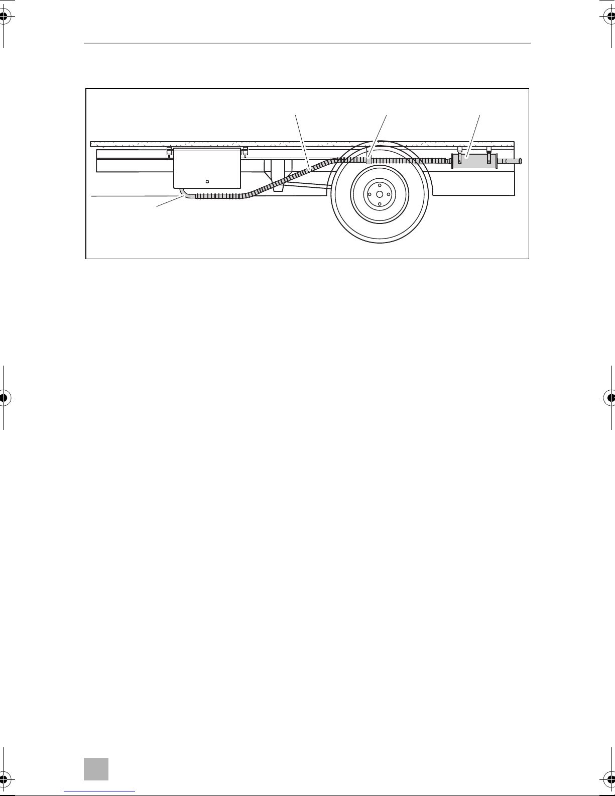
8.4 Installing the tank and fuel supply line
Please observe the following instructions for the installation location:
• The tank bottom must be positioned at a maximum of 0.3 m below the bottom of
the generator.
• The top of the tank must not be higher than the top of the generator.
➤ Lay the fuel line as straight as possible.
➤ Secure the tank, see fig. c and chapter “Connecting the float” on page 27.
18
Page 19

EN
TEC29 EV AUS Installation
d
8.5 Mounting the digital control panel
Please observe the following instructions for the installation location:
• Observe the length of the extension cable from the digital control panel to the
generator.
126
105
10.5
22
5
38
76
30
➤ Drill the holes as shown in fig. d.
➤ Insert the plug into the digital control panel.
➤ Screw on the digital control panel.
1
2
19
Page 20

EN
Connecting the electrical power to the generator TEC29 EV AUS
9 Connecting the electrical power to the
generator
DANGER! Danger of electrocution
D
A
Make sure there is no voltage at electrically operated components
before carrying out work on them!
NOTICE!
Protect the system with an RCD breaker according to AS3001
regulation.
NOTE
Observe the applicable guidelines in the country of the consumer.
I
9.1 Important notes on the electrical connection
• Only a qualified electrician should connect the generator to the electrical power.
• Check that the voltage specification on the type plate is the same as that of the
power supply.
• Do not lay the 230 Vw mains cable and the 12 Vg cable together in the same
cable duct.
• Do not lay cables which are loose or bent next to electrically conductive material
(metal).
• Connect the generator to a power circuit which can supply the necessary current
(see chapter “Technical data” on page 46).
• Select the cross-section of the cable as follows:
– 230 V: 2.5 mm²
– Battery connection (length < 6 m): 10 mm²
– Battery connection (length > 6 m): 16 mm²
• Install a manual main switch which can disconnect all the consumers from the
generator with the exception of the battery.
20
Page 21

EN
TEC29 EV AUS Connecting the electrical power to the generator
9.2 Circuit diagrams
The complete circuit diagram can be found in fig. e, page 22.
Item Description
1 3-phase winding
2 Auxiliary winding
3 Battery charger
4Inverter
5 Generator connector
6 Stepper motor
7 Main switch
8 Thermal disconnector
9 Battery positive terminal
10 Battery
11 Interface module
12 Electromagnet for cold start
13 Motor coil
14 Oil level gauge
15 Starter motor
16 Starter relay
17 Internal control panel
18 4-pin plug
19 Digital control panel
21
Page 22

EN
2
34
5
67
8
9121
85
85
86
86
303087
87
-
+
+
CN1
neutral
phase
1
234
9
1
234
1
2
3
4
red
432
1
165
432
2
345
6
1
3
241
CN2
CN3
CN4
CN5
CN6
M
19
4
18
6
3
5
1
2
10
7
11
8
13
14
15
16
12
9
17
e
Connecting the electrical power to the generator TEC29 EV AUS
22
Page 23

EN
TEC29 EV AUS Connecting the electrical power to the generator
2
3
5
4
6
8
109
7
1
f
Control panel
Item in
fig. f
1 Main switch
2 Main fuse
3 Battery charger fuse
4 Digital control panel connection
5 Connector for service purposes
6 Battery positive terminal
7 230 V connection
8 Earth
9 Float connection (petrol tank)
10 No connection required
Description
23
Page 24

EN
Connecting the electrical power to the generator TEC29 EV AUS
9.3 Connecting 230 V
NOTICE!
A
➤ Guide the 230 V connection cable through the cable passage in the housing and
connect it to the 230 V terminals (fig. f 7, page 23).
➤ Connect the earth cable to the earth connection on (fig. f 8, page 23).
• Connect a relay or a change over switch to the vehicle’s electrical
system so that the generator is not damaged when the external
mains is connected (according to AS3001 regulation).
• The neutral conductor is internally linked to the PE conductor. To
protect against automatic shutdown, make sure that a safety switch
(RCD switch, 30 mA) and an in all-pole overcurrent protection (e.g.
circuit breaker, 12 A) are installed (according to AS3001 regulation)
between the generator and the change over switch.
9.4 Connecting the starter battery
NOTICE!
A
➤ Connect the positive terminal of the battery to the positive battery terminal
connection using a cable with a cross-section of 10 mm² for a length of < 6 m or
16 mm² for a length of > 6 m (fig. f 6, page 23).
➤ Fit a 100 A fuse in the positive cable near the positive terminal of the starter
battery to protect the generator’s electrical system.
The starter battery must have 12 V and a capacity of at least 60 Ah. Make
sure that the battery is fully charged.
24
Page 25

EN
TEC29 EV AUS Connecting the electrical power to the generator
g
1
➤ Connect the negative terminal of the battery using a cable with a suitable cross-
section (see above) via the insert of the generator (fig. g 1).
➤ Connect the earth connection on the generator to the vehicle chassis.
Remove any paint or rust from the chassis if necessary to ensure good contact.
➤ Protect the connections by applying lubrication.
9.5 Configuring the automatic mode
NOTE
I
• You can only use automatic mode:
– if the vehicle is stationary and the ignition is switched off
• To shorten charging times, an additional charging unit with at least
20 A can be installed between the generator and disconnector
switch, especially if batteries with a capacity of more than 60 Ah are
used. In this case remove the fuse (fig. f 3, page 23) from the
internal control panel.
In automatic mode, the generator switches on automatically and charges the battery
if the voltage of the connected battery is too low.
25
Page 26

EN
Connecting the electrical power to the generator TEC29 EV AUS
h
The generator switches off automatically once the battery has been fully charged.
The circuit diagram for the automatic mode can be found in fig. h.
Remote switch
(not included)
white
black
Vehicle ignition key
ON
Switch 1
(not included)
➤ Connect the black wire to switch 1 (not included in the scope of delivery).
➤ Lead the black wire from switch 1 to the ground through a connection managed
by the ignition key.
➤ Connect the white wire to a suitable switch.
9.6 Connecting the digital control panel
➤ Connect the provided extension cable to the digital control panel (fig. d 2,
page 19) and the generator control panel (fig. f 4, page 23).
Connecting the autostart wiring
➤ Connect the provided wiring to the digital control panel (fig. d 1, page 19).
➤ To enable the autostart function, connect the black wiring as shown in fig. h,
page 26.
➤ To enable the remote ON/OFF function, connect the white wiring as described
in fig. h, page 26.
26
Page 27

EN
TEC29 EV AUS Connecting the electrical power to the generator
9.7 Connecting the float
➤ Connect the float from the tank to the float connection (fig. f 9, page 23).
9.8 Connecting two genarators in parallel
NOTE
Use only one starter battery to start both generators.
I
When connecting the generators, note the following:
• It is not possible to connect more than two generators in parallel.
• To start one generator at a time the starter battery capacity has to be according
to the generator manual (minimum capacity: 60 Ah).
To start both generators at the same time you have to double the battery
capacity.
• The cross section of the battery connection cable for each generator has to be at
least:
– 10 mm² if the total length is less than 6 m
– 16 mm² if the total length is more than 6 m
NOTE
I
Proceed as follows (fig. i, page 28):
➤ Connect each generator to a junction box (1; not included in the scope of
delivery).
The minimum cross section for each generator output cable is 2.5 mm².
➤ Create a single output for the load (2) inside the junction box (1).
The minimum cross section for the parallel output cable is 6 mm².
➤ Connect the battery‘s negative pole to ground.
➤ Connect the output ground cable to ground.
➤ To properly run the generators in parallel connect the inverters (4) of each
genarator using the parallel cable (3; available as accessory).
• The maximum distance between each generator to the junction box
is 15 m.
• The maximum length difference between the output cables of the
generators must be 2 m.
27
Page 28

EN
Connecting the electrical power to the generator TEC29 EV AUS
Line
Neutral
12 V
#1
Line
Neutral
12 V
#2
+12 V
+12 V
Load
3
4
3
1
2
i
28
Page 29

EN
TEC29 EV AUS Operating the generator
10 Operating the generator
NOTICE!
A
I
10.1 Basic notes on operation
!
Do not run the generator over 70 % of the maximum constant output for
the first 50 operating hours (run-in phase).
NOTE
Run the generator at a maximum of approx. 75 % of the maximum
continuous load after the run-in phase.
By doing this you can prolong the service life of the generator and
maximise its efficiency.
CAUTION! Beware of injury
Do not insert your fingers or objects into the air nozzles or the intake
grille.
Please note the following basic information:
• Always check the oil level before use (chapter “Checking the oil level” on
page 34).
• Leave the generator running for a few minutes after use without any consumers
before stopping it.
• If you are not using your generator for a longer period of time, start it up at least
every 30 days and leave it running for 15 minutes or more.
10.2 Switching the generator to standby or no function
The generator can be switched to standby or no function with the main switch
(fig. 3 1, page 10) in the control panel.
29
Page 30

EN
Operating the generator TEC29 EV AUS
10.3 Switching the digital control panel on and off
This switch (fig. 4 2, page 11) on the digital control panel is for switching the digital
control panel on and off.
➤ Switch the digital control panel on with the on/off switch.
✓ The display shows:
The display switches off automatically after 5 minutes if the start button is not
touched within this time.
Press and hold the start button for 4 s to switch on the display again.
✓ The generator can now be started.
GEN OFF.
10.4 Starting the generator
The generator can only be started if it is in standby and the digital control panel is
switched on.
➤ Start up the generator by pressing the start/stop button (fig. 4 3, page 11).
10.5 Stopping the generator
➤ Stop the generator by pressing the start/stop button (fig. 4 3, page 11).
If the generator does not stop: switch it off by pressing the red on/off button or
by pressing the main switch (fig. 3 1, page 10) on the internal control panel.
30
Page 31

EN
TEC29 EV AUS Operating the generator
10.6 Operating two generators in parallel (optional)
NOTE
The maximum allowed load for the parallel system is 4800 W.
I
You can independently turn each generator on and off. If the load is more than
2600 W, you can start both generators in parallel.
If the parallel cable is connected, each control panel shows the status of the parallel
system:
• “GEN ON” (fig. 4 10, page 11): Stand alone operation of one generator.
The second generator is completely turned off (the control panel is switched off
and/or the maintenance switch is turned off). In this case the running generator
cannot recognize the second generator.
• “–GEN ON” (fig. 4 10, page 11): Stand alone operation of one generator.
The second generator is in stand-by and can be started.
• “=GEN ON” (fig. 4 10, page 11): Both generators are running in parallel.
The power output (fig. 4 7, page 11) shown is the power generated by each
single generator. The total power output is the sum of both values.
31
Page 32

EN
Operating the generator TEC29 EV AUS
10.7 Display messages
To reset the digital control panel when a message appears, press the on/off switch.
Display message
Description
LOW BATTERY
The battery voltage has fallen
below the minimum value for
starting up (9V).
OIL CHANGE
The number of prescribed operating hours has been reached for
changing the engine oil.
FUEL LOW
The fuel in the tank is in reserve.
OIL ALERT
Insufficient engine oil.
GENERATOR ALERT!
General alarm message
Example: The control ring on the
throttle valve of the carburettor
(stepper motor) is faulty.
Generator behaviour Measures
The generator does not start. Charge the battery.
The generator continues to run. Change the oil (see chapter
“Changing the oil” on page 39),
then restart the generator by
pressing and holding down the
start button.
The generator continues to run. Refuel.
The generator stops. Fill up with oil (see chapter
“Checking the oil level” on
page 34).
The generator stops. Check the system by referring to
the troubleshooting table.
If the problem persists, contact
the manufacturer's branch office
in your country (addresses on the
back page).
OVERLOAD!
The consumers generate an
overload at the output.
SHORT CIRCUIT
The consumers cause a short
circuit at the output.
OVER TEMPERATURE
Overheating
32
The inverter switches off, therefore no voltage is supplied but
the engine carries on running
until it goes off.
The inverter switches off, therefore no voltage is supplied but
the engine carries on running
until it goes off.
The inverter switches off so no
voltage is supplied to cool the
generator, but the engine
wcarries on running.
Reduce the connected load and
start the generator again.
Check the connected
consumers then start the
generator again.
Leave the engine to cool down
for a few minutes then start the
generator again.
Page 33

EN
TEC29 EV AUS Operating the generator
Display message
Description
GEN CAL
Message appears when the
generator is started up; it shows
the calibration phase which
takes place before each start-up.
The generator does not supply
any voltage.
GEN WAIT
Message appears while you are
waiting for the generator to start
again.
GEN ON
The generator is operating
normally.
–GEN ON
Generator behaviour Measures
The generator is running but
does not supply any voltage.
The generator is switched off. Wait until the message has
Normal mode –
A second generator is in standby and can be started.
Wait a moment.
disappeared then attempt
ignition again.
–
=GEN ON
GEN OFF
ENABLE AUTOSTART [HOLD]
CONFIRM
Message appears when the
automatic mode is switched on.
GEN AUTO
Automatic mode
PARALLEL ERROR
Parallel operation of two
generators
COOLING
Two generators run in parallel. –
The generator is in stand-by and
can be started.
Controls are waiting for user
input
The automatic mode is switched on–
The generators don‘t run properly in parallel. Both generators
stop.
The generator keeps on running
but the inverter is off.
–
Press the start button within
15 seconds and hold down for
4seconds.
Check the parallel cable and
replace it, if necessary.
To reset the alarm switch each
generator off and on by pressing
the red on/off button.
Wait until the unit cools down;
the generator will automatically
turn off.
33
Page 34

EN
Operating the generator TEC29 EV AUS
2
3
4
1
j
10.8 Checking the oil level
CAUTION!
!
Hot oil can cause burns.
Only check the oil level when the generator is switched off.
NOTE
The generator must be level.
I
Always check the oil level before use. To do this, proceed as follows (fig. j):
➤ Open the generator front door.
➤ Switch the generator to no function with the main switch (1).
➤ Disconnect the positive terminal of the supply battery.
➤ Take the dipstick (2) out of the filler neck (3).
➤ Clean the dipstick (2) with a cloth.
➤ Put the dipstick (2) back into the filler neck (3).
34
Page 35

EN
TEC29 EV AUS Operating the generator
➤ Take the dipstick (2) out of the filler neck.
➤ Check that the oil level is between the notch (maximum filling level) and the tip of
the dipstick (4).
If not, top up with more oil.
➤ Put the dipstick (2) back into the filler neck (3).
➤ Check that the oil level is not above the maximum level.
➤ Connect the generator to the positive terminal of the supply battery.
➤ Switch the generator to standby with the main switch (1).
➤ Close the generator front door.
10.9 Switching to automatic mode
You can only switch to automatic mode:
• if it was configured when the generator was installed (see chapter “Connecting
the autostart wiring” on page 26
• if the vehicle is stationary and the ignition is switched off
In automatic mode, the generator switches on automatically and charges the battery
if the voltage of the connected battery is too low.
The generator switches off automatically once the battery has been fully charged.
The generator can also be turned ON/OFF using a remote switch (not provided) as
indicated in fig. h, page 26.
To switch on the automatic mode:
➤ Switch on the automatic mode switch (if available).
➤ Switch the ignition off.
➤ Switch the digital control panel on by pressing the on/off switch.
✓ The display shows:
NOTE
GEN OFF appears on the display instead of ENABLE AUTOSTART [HOLD]
If
I
CONFIRM
is the case, contact the specialist workshop which installed the generator and have the automatic mode retrofitted.
, the automatic mode is not configured for your generator. If this
ENABLE AUTOSTART [HOLD] CONFIRM.
35
Page 36

EN
Cleaning the generator TEC29 EV AUS
➤ Press the start button within 15 seconds and hold it down for 4 seconds.
✓ The display shows:
➤ The automatic mode is switched on.
GEN AUTO.
10.10 Switching off the automatic mode
➤ Switch off the automatic mode switch (if available).
or
➤ Switch on the ignition.
✓ The display shows:
GEN OFF.
11 Cleaning the generator
NOTICE! Beware of damage
A
• Do not clean the generator with a high-pressure cleaner. Exposure
to water can damage the generator.
• Do not use sharp or hard objects or cleaning agents for cleaning as
these may damage the generator.
• To clean the generator, use water with a gentle cleaning agent.
Never use petrol, diesel or solvents.
➤ Clean the generator with a damp cloth from time to time.
➤ Remove any dirt from the air vents in the generator at regular intervals. Make sure
you do not damage the grilles of the generator in the process.
36
Page 37

EN
TEC29 EV AUS Servicing the generator
12 Servicing the generator
NOTE
I
12.1 Maintenance table
!
I
Find your Dometic service partner on the internet:
http://service-location.dometic.com
WARNING!
Only have maintenance work carried out by specialist personnel who
are familiar with the relevant regulations. Inadequate maintenance may
cause serious hazards.
NOTE
Have the following maintenance work performed at regular intervals or
after the specified number of operating hours, whichever is sooner.
Interval Inspection/maintenance
In the first month
or after 20 hours
Every 3 months or
after 50 hours
Every 6 months or
after 100 hours
After 150 hours ➤ Check and clean the spark arrestor.
Once a year or
every 300 hours
Every two years ➤ Check the petrol supply lines.
➤ Change the oil.
➤ Check the air filter (chapter “Servicing the air filter” on page 40).
➤ Check the air filter (chapter “Servicing the air filter” on page 40).
➤ Change the oil.
➤ Check the spark plug (chapter “Servicing the spark plugs” on
page 42).
➤ Check the valves‘ adjustment.
➤ Check the fuel tank and fuel filter.
➤ Check the vibration damper.
37
Page 38

EN
Servicing the generator TEC29 EV AUS
1
1
3
2
k
12.2 Preparing maintenance work
CAUTION!
!
➤ Switch the generator to the off position with the main switch (fig. j 1, page 34).
➤ Disconnect the positive terminal of the supply battery.
➤ Open the generator front door.
For maintenance work, you can take the generator out (fig. k):
Note the following for all maintenance work:
• The generator must not be running.
• All the parts must be cooled down.
WARNING!
!
➤ Undo the fastening screws (1).
➤ Remove the mounting plate (2) with the generator from the housing (3).
38
The mounting plate with generator is very heavy (> 40 kg) and could fall
out the housing if you take it out too far.
Page 39

EN
TEC29 EV AUS Servicing the generator
1
l
12.3 Finishing maintenance work
➤ Connect the generator to the positive terminal of the supply battery.
➤ Switch the generator to standby with the main switch (fig. j 1, page 34).
➤ Close the generator front door.
12.4 Changing the oil
CAUTION!
Hot oil can cause burns.
!
NOTICE!
A
Only dispose of used oil at a specialist recycling station and observe the
local laws for environmental protection.
You may use the following oil:
• API SG or SF grade oil for four-stroke engines.
• SAE 10W-30 grade oil (can be used at any temperature).
• Oil with single grade oil viscosity.
Select the appropriate viscosity according to the average temperature on-site.
Change the oil as follows (fig. l):
39
Page 40

EN
Servicing the generator TEC29 EV AUS
➤ Allow the generator to run until warm so that the oil can drain off faster and
completely.
➤ Place a suitable receptacle under the drain plug (1).
➤ Take out the drain plug (1).
✓ The oil drains off.
➤ Pour fresh oil into the nozzle.
The amount of oil is: 0.6 l.
12.5 Servicing the air filter
WARNING! Danger of explosions
!
Do not use diesel oil or solvents with low boiling points for cleaning the
air filter. They could ignite or explode.
A
I
NOTICE!
Never leave the engine running without an air filter. Otherwise this
quickly wears out the engine.
NOTE
If the air filter is dirty, the air flow to the carburettor is reduced. Check the
filter regularly so that the carburettor can function properly. Check this
more frequently if the generator is being used in particularly dusty
environments.
40
Page 41

EN
TEC29 EV AUS Servicing the generator
234 1
m
Service the oil filter as follows (fig. m):
➤ Prepare the maintenance work and pull the generator out of the housing slightly:
see chapter “Preparing maintenance work” on page 38.
➤ Remove the butterfly nut (1) and the filter cover (2).
➤ Remove the butterfly nut (3).
➤ Take out the air filter (4).
The air filter consists of two parts: a sponge filter and a paper filter.
➤ Check the condition of both parts of the filter carefully. Replace the damaged
filter parts.
➤ Clean the undamaged filter parts; see the following section.
➤ Finish the maintenance work, see chapter “Finishing maintenance work” on
page 39.
Cleaning the sponge filter
➤ Wash the sponge with a neutral detergent solution and rinse it thoroughly.
➤ Leave the sponge to dry completely.
➤ Soak the sponge in fresh engine oil.
➤ Squeeze out the excess oil.
41
Page 42

EN
Servicing the generator TEC29 EV AUS
0.7 – 0.8 mm
1
n
Cleaning the paper filter
➤ Knock the dirt off the paper by banging it lightly on a hard surface or use com-
pressed air to blow through the filter.
Do not brush the paper as this will push the dirt into the fibres of the paper filter.
➤ Change the paper filter if it is heavily soiled.
12.6 Servicing the spark plugs
NOTICE!
A
• Screw the spark plugs in carefully. A loose spark plug can get very
hot and damage the engine.
• Only use the same type of spark plugs.
• When you insert a new spark plug, screw it in by 1/2 a turn once it is
firmly on the washer. If you are using used spark plugs, turning them
1/8 or 1/4 is suffice.
➤ Prepare the maintenance work, see chapter “Preparing maintenance work” on
page 38.
➤ Remove the spark plug connector.
➤ Remove the spark plug using a spark plug wrench.
➤ Make a visual inspection of the spark plugs.
Replace the spark plug if it is clearly worn or the isolator is damaged or broken.
If the spark plug is just dirty, clean it with a steel brush.
42
Page 43

EN
TEC29 EV AUS Troubleshooting
➤ Measure the distance between the electrodes with a thickness gauge (fig. n,
page 42). It must be 0.7 – 0.8 mm and can be corrected by bending the electrode if necessary.
➤ Check whether the spark plug seal is intact.
➤ If so, screw in the spark plugs by hand to avoid damaging the thread.
➤ Tighten the spark plugs using a spark plug wrench so that the washer is pressed
together.
➤ Finish the maintenance work, see chapter “Finishing maintenance work” on
page 39.
13 Troubleshooting
Fault Cause Remedy
The digital control
panel does not
come on when the
on/off switch is
pressed.
The starter does
not work when the
start button is
pressed.
Starter battery is flat (9 V). ➤ Charge the starter battery.
Power cable is disconnected or the plug
is removed.
Generator earth cable is disconnected or
the fuse (if available) is blown.
Starter battery is flat. ➤ Charge the starter battery.
The main switch is at “0”. ➤ Set the main switch to “I” or “1”.
Starter shaft is dirty. ➤ Clean the starter shaft.
Too much oil in the engine. ➤ Drain the oil.
Inverter is damaged. ➤ Contact an authorised workshop.
Power cable is disconnected or the plug
is removed.
Generator earth cable is disconnected or
the fuse (if available) is blown.
Starter is not receiving any power.
➤ Contact an authorised workshop.
43
Page 44

EN
Troubleshooting TEC 29 EV AUS
Fault Cause Remedy
The starter turns
but the generator
does not start.
The generator
tends to stall.
Not enough fuel in the fuel pipe or fuel
tank is empty.
Spark plug is not receiving any power. ➤ Check the electric connections.
Carburettor is not receiving any petrol. ➤ Clean the carburettor.
Air intake is blocked. ➤ Check the air filter (see chapter
Inverter is damaged. ➤ Contact an authorised workshop.
Power cable is disconnected or the plug
is removed.
Too much oil in the engine. ➤ Drain the oil.
Load is over 2.6 kW. ➤ Reduce the consumers.
Carburettor is not receiving any petrol. ➤ Clean the carburettor.
Air intake is blocked. ➤ Check the air filter (see chapter
➤ Fill up with petrol.
“Servicing the air filter” on
page 40).
“Servicing the air filter” on
page 40).
The generator is
running but does
not supply any voltage.
The generator
starts up very fast
and then the
“GENERATOR
ALERT” message
appears.
The generated
voltage is unstable.
Inverter is damaged. ➤ Contact an authorised workshop.
Electromagnet is blocked.
Air filter is dirty.
Inverter is damaged. ➤ Contact an authorised workshop.
The stepper motor is faulty or the cable is
disconnected.
Electromagnet is blocked.
The throttle valve is blocked.
Generic alarm ➤ If the problem persists, contact an
authorised workshop.
Inverter is damaged. ➤ Contact an authorised workshop.
The stepper motor is faulty or the cable is
disconnected.
Inverter is damaged. ➤ Contact an authorised workshop.
The stepper motor is faulty or the cable is
disconnected.
44
Page 45

EN
TEC29 EV AUS Warranty
14 Warranty
The statutory warranty period applies. If the product is defective, please contact the
service partner in your country (addresses on the back on the instruction manual).
Our experts will be happy to help you and will discuss the warranty process with you
in more detail.
15 Disposal
➤ Place the packaging material in the appropriate recycling waste bins wherever
possible.
If you wish to finally dispose of the product, ask your local recycling centre
or specialist dealer for details about how to do this in accordance with the
M
applicable disposal regulations.
B
Protect the environment!
Do not dispose of any batteries with general household waste.
Return defective or used batteries to your retailer or dispose of them at
collection points.
45
Page 46

EN
Technical data TEC29 EV AUS
16 Technical data
Dometic TEC29 EV AUS
Ref. no.: 9102900291
Rated output voltage: 230 Vw / 50 Hz
Max. constant output
(at 25 °C at sea level):
Derating altitude: 3.5 % derating every 300 m increase in
Derating temperature: 1 % derating every 5.6 °C increase in
Battery charger output voltage: 12 V g
Battery charger max. output current: 10 A
Operating temperature range: –15 °C to +50 °C
Distortion factor: < 3 %
Fuel: RON 91 regular grade petrol
Average consumption: max. 1.2 l/h
Motor output: 4.0 kW (5.5 PS)
Sound level at distance of 7 m: 54 – 59 dB(A)
2600 W
altitude
temperature.
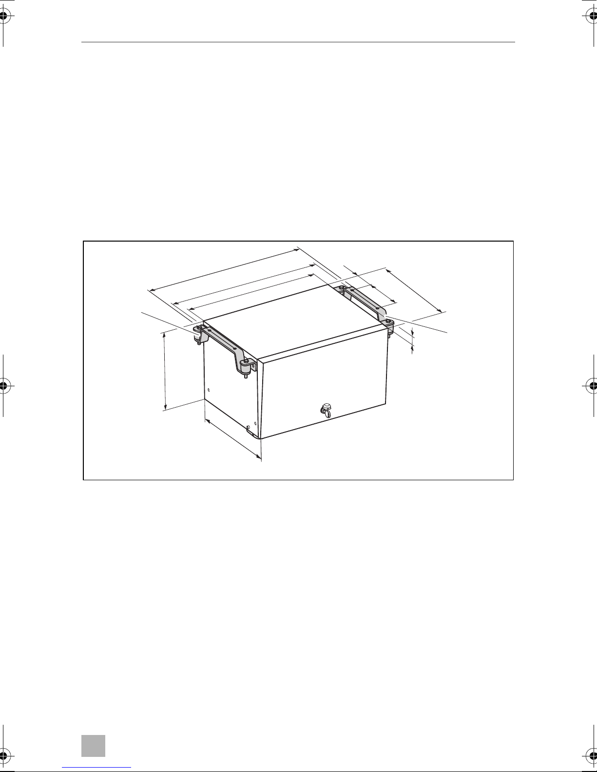
Dimensions: see fig. o, page 47
Weight: 44 kg
Inspection/certification:
24
46
Page 47

EN
TEC29 EV AUS Technical data
387 580
548
480360
290
160 100
o
47
Page 48

AUSTRALIA
Dometic Australia Pty. Ltd.
1 John Duncan Court · Varsity Lakes QLD 4227
1800 212121 · +61 7 55076001
Mail: sales@dometic.com.au
dometic.com
service-location.dometic.com
AUSTRIA
Dometic Austria GmbH
Neudorferstraße 108
A-2353 Guntram sdorf
+43 2236 908070
+43 2236 90807060
Mail: info@dometic.at
BENELUX
Dometic Branch Office Belgium
Zincstraat 3
B-1500 Halle
+32 2 3598040
+32 2 3598050
Mail: info@dometic.be
BRAZIL
Dometic DO Brasil LTDA
Avenida Paulista 1754, conj. 111
SP 01310-920 Sao Paulo
+55 11 3251 3352
+55 11 3251 3362
Mail: info@dometic.com.br
DENMARK
Dometic Denmark A/S
Nordensvej 15, Taulov
DK-7000 Fredericia
+45 7558 5966
+45 75586307
Mail: info@dometic.dk
FINLAND
Dometic Finland OY
Mestarintie 4
FIN-01730 Vantaa
+358 20 7413220
+358 9 7593700
Mail: info@dometic.fi
FRANCE
Dometic SAS
ZA du Pré de la Dame Jeanne
B.P. 5
F-60128 Plailly
+33 3 44633525
+33 3 44633518
Mail : vehiculesdeloisirs@dometic.fr
GERMANY
Dometic WAECO International GmbH
Hollefeldstraße 63
D-48282 Emsdetten
+49 (0) 2572 879-195
+49 (0) 2572 879-322
Mail: info@dometic-waeco.de
HONG KONG
Dometic Group Asia Pacific
Suites 2207-11 · 22/F · Tower 1
The Gateway · 25 Canton Road,
Tsim Sha Tsui · Kowloon
+852 2 4611386
+852 2 4665553
Mail: info@waeco.com.hk
HUNGARY
Dometic Zrt. Sales Office
Kerékgyártó u. 5.
H-1147 Budapest
+36 1 468 4400
+36 1 468 4401
Mail: budapest@dometic.hu
ITALY
Dometic Italy S.r.l.
Via Virgilio, 3
I-47122 Forlì (FC)
+39 0543 754901
+39 0543 754983
Mail: vendite@d ometic.it
JAPAN
Dometic KK
Maekawa-Shibaura, Bldg. 2
2-13-9 Shibaura Minato-ku
Tokyo 108-0023
+81 3 544 5 3333
+81 3 5445 3339
Mail: info@dometic.jp
MEXICO
Dometic Mx, S. de R. L. d e C. V.
Circuito Médicos No. 6 Local 1
Colonia Ciudad Satélite
CP 53100 Naucalpan de Juárez
Estado de México
+52 55 5374 4108
+52 55 5393 4683
Mail: info@dometic.com.mx
NETHERLANDS
Dometic Benelux B.V.
Ecustraat 3
NL-4879 NP Etten-Leu r
+31 76 5029000
+31 76 5029019
Mail: info@dometic.nl
NEW ZEALAND
Dometic New Zealand Ltd.
PO Box 12011
Penrose
Auckland 1642
+64 9 622 1490
+64 9 622 1573
Mail: customerservices@dometic.co.nz
NORWAY
Dometic Norway AS
Østerøyveien 46
N-3232 Sandefjord
+47 33428450
+47 33428459
Mail: firmapost@dometic.no
POLAND
Dometic Poland Sp. z o.o .
Ul. Puławska 435A
PL-02-801 Warszaw a
+48 22 41 4 3200
+48 22 414 3201
Mail: info@dometic.pl
PORTUGAL
Dometic Spain, S.L.
Branch Office em Portugal
Rot. de São Gonçalo nº 1 – Esc. 12
2775-399 Carcavelos
+351 219 244 173
+351 219 243 206
Mail: info@dometic.pt
RUSSIA
Dometic RUS LLC
Komsomolskaya square 6-1
RU-107140 Moscow
+7 495 780 79 39
+7 495 916 56 53
Mail: info@dometic.ru
SINGAPORE
Dometic Pte Ltd
18 Boon Lay Way 06–140 Trade Hub 21
Singapore 609966
+65 6795 3177
+65 6862 6620
Mail: dometic@dometic.com.sg
SLOVAKIA
Dometic Slovakia s.r.o. Sales Office Bratislava
Nádražná 34/A
900 28 Ivanka pri Duna ji
/ +421 2 45 529 680
Mail: bratislava@ dometic.com
SOUTH AFRICA
Dometic (Pty) Ltd.
Regional Office
South Africa & Sub-Saharan Africa
Unit 6-7 on Mastiff Linbro Park
2008 Johannesburg
+27 11 4504978
+27 11 4504976
Mail: info@dometic.co.za
SPAIN
Dometic Spain S.L.
Avda. Sierra del Guadarrama, 16
E-28691 Villanueva de la Cañada
Madrid
+34 902 1 11 042
+34 900 100 245
Mail: info@dometic.es
SWEDEN
Dometic Scandinavia AB
Gustaf Melins gata 7
S-42131 Västra Frölunda
+46 31 7341100
+46 31 7341101
Mail: info@dometicgroup.se
SWITZERLAND
Dometic Switzerland AG
Riedackerstrasse 7a
CH-8153 Rümlang
+41 44 81 87171
+41 44 8187191
Mail: info@dometic.ch
UNITED ARAB EMIRATES
Dometic Middle East FZCO
P. O. Box 17860
S-D 6, Jebel Ali Freezone
Dubai
+971 4 883 3858
+971 4 883 3868
Mail: info@dometic.ae
UNITED KINGDOM
Dometic UK Ltd.
Dometic House, The Brewery
Blandford St. Mar y
Dorset DT11 9LS
+44 344 6 26 0133
+44 344 626 0143
Mail: customerservices@dometic.co.uk
USA
Dometic RV Division
1120 North Main Street
Elkhart, IN 46515
+1 574-264-2131
4445102097 03/2017 ST0207
 Loading...