

Page 1
ENDEFR
ESPTIT
NLDASVNOFIRUPLSKCS
HU
ENERGY & LIGHTING
GENERATORS
Generator
Monteringsanvisning . . . . . . . . . . . . . . . . 181
Generaattori
Asennusohje . . . . . . . . . . . . . . . . . . . . . . . 199
Генератор
Инструкция по монтажу. . . . . . . . . . . . . . 217
Generator
Instrukcja montażu . . . . . . . . . . . . . . . . . . 237
Generàtor
Návod na montáž . . . . . . . . . . . . . . . . . . . 256
TEC29 EV, TEC29 EV LPG
Generator
Installation Manual. . . . . . . . . . . . . . . . . . . . 15
Generator
Montageanleitung. . . . . . . . . . . . . . . . . . . .33
Générateur
Instructions de montage . . . . . . . . . . . . . . .52
Generador
Instrucciones de montaje . . . . . . . . . . . . . . 71
Gerador
Instruções de montagem . . . . . . . . . . . . . .90
Generatore
Indicazioni di montaggio . . . . . . . . . . . . .109
Generator
Montagehandleiding . . . . . . . . . . . . . . . . 127
Generator
Monteringsvejledning. . . . . . . . . . . . . . . .145
Generàtor
Návod k montáži. . . . . . . . . . . . . . . . . . . . 274
Generátor
Szerelési útmutató . . . . . . . . . . . . . . . . . . 292
Generator
Monteringsanvisning. . . . . . . . . . . . . . . . .163
Page 2

Page 3
TEC29 EV, TEC29 EV LPG
1
2
1 2
12
13
4
3
5
9876
1110
580
548
480
99
160
385
1
1
10.5
290
360
3
Page 4
TEC29 EV, TEC29EVLPG
548
23
20
35
104
310
295
360
30
1
2
3
2
1
3 4
4
5
4
Page 5
TEC29 EV, TEC29 EV LPG
6
7
8
5
Page 6
TEC29 EV, TEC29EVLPG
9
0
max. 2 m
max. 0.3 m
6
Page 7
TEC29 EV, TEC29 EV LPG
a
b
76
38
126
10510,5
20
7,5
Ø30
7
Page 8
6
542
31
11109
87
12
4321
12
1
2
0/1
M
12
B
230
230
23
22
4
5
21
8
7
6
1
2
25
3
24
20
17
16
18
15
13
12
10
9
11
19
14
cy
cy
cy
br
br
wssw
ws
ws
ws
sw
sw
gr
sw
ge
gr
rt
rt
rt
vt
pk
bl
sw
br
ge
gn
ws
gr
12 11 10 9 8 7 6 5 4 3 2 1
ws
ws
gr
rt
pk
sw
or
sw
bl
vt
br
ws
ge
gr
rt
pk
sw
gn
bl
vt
br
1098765 4321
98765 4321
c
TEC29 EV, TEC29EVLPG
8
Page 9
d
TEC29 EV, TEC29 EV LPG
25
sw
2
27
gr
1
or
1
sw
ge
234
br
24
swrt
21
sw
5
rt
rt
rt
M
10
ENGINE
sw
28
sw
sw
15
rt
rt
sw
13
vt
8
br
17
neutral
bl
Phase
sw
1
GND
4
GE-GN
sw
sw
2
3
1
234
cycycy
ws
rt
6
ws
gr
sw
sw
or
bl
bl
14
5
br
br
123 456
rt
12
or
18
rt
12
26
16
11
12
23
ws
ws
rt
4812935
sw
gr
vt
br
rt
9
gr
sw
22
1
sw
2345678
vt
pk
rt
gr
ws
1
2345678
20
9
10
bl
gn
br
ge
sw
9
10
7
19
9
Page 10
TEC29 EV, TEC29EVLPG
9
8
7
6
5
4
3
2
1
e
1
2
3
4
5
7
8
6
f
10
Page 11

TEC29 EV, TEC29 EV LPG
g
h
2
1
Remote switch
(not included)
white
black
Switch 1
(not included)
Vehicle ignition key
ON
11
Page 12
1
7
4
9
6
A
B
3
230 V
230 V
12 V
230 V / 1~
AG 102
1
2
3
+12 V
rt
i
TEC29 EV, TEC29EVLPG
12
Page 13
Line
Neutral
12 V
#1
Line
Neutral
12 V
#2
+12 V
+12 V
Load
1
3
3
4
2
j
TEC29 EV, TEC29 EV LPG
13
Page 14
TEC29 EV, TEC29EVLPG
bl br cy ge gn gr
EN Blue Brown Cyan Yellow Green Grey
DE Blau Braun Cyan Gelb Grün Grau
FR Bleu Marron Cyan Jaune Vert Gris
ES Azul Marrón Cian Amarillo Verde Gris
PT Azul Castanho Ciano Amarelo Verde Cinzento
IT Blu Marrone Cyan Giallo Verde Grigio
NL Blauw Bruin Cyaan Geel Groen Grijs
DA Blå Brun Cyan Gul Grøn Grå
SV Blå Brun Cyan Gul Grön Grå
NO Blå Brun Cyan Gul Grønn Grå
FI Sininen Ruskea Syaani Keltainen Vihreä Harmaa
RU Синий Коричневый Голубой Желтый Зеленый Серый
PL Niebieski Brązowy Cyjan Żółty Zielony Szary
SK Modrá Hnedá Azúrová Žltá Zelená Sivá
CS Modrá Hněda Azurová Žlutá Zelená Šedá
HU Kék Barna Cián Sárga Zöld Szürke
or pk rt sw vt ws
EN Orange Pink Red Black Violet White
DE Orange Pink Rot Schwarz Violett Weiß
FR Orange Rosa Rouge Noir Violeta Blanc
ES Naranja Rose Rojo Negro Lila Blanco
PT Cor de laranja Cor de rosa Vermelho Preto Violeta Branco
IT Arancione Rosa Rosso Nero Violetto Bianco
NL Oranje Roze Rood Zwart Paars Wit
DA Orange Lyserøde Rød Sort Violet Hvid
SV Orange Rosa Röd Svart Violett Vit
NO Oransje Rosa Rød Svart Fiolett Hvit
FI Oranssi Pinkki Punainen Musta Violetti Valkoinen
RU Оранжевый Розовый Красный Черный Фиолетовый Белый
PL Pomarańczowy Różowy Czerwony Czarny Fioletowy Biały
SK Oranžová Ružová Červená Čierna Fialová Biela
CS Oranžová Růžová Červená Černá Fialová Bílá
HU Narancs Rózsaszín Piros Fekete Ibolya Fehér
14
Page 15

EN
TEC29 EV, TEC29 EV LPG
Please read this instruction manual carefully before installation and first
use, and store it in a safe place. If you pass on the product to another
person, hand over this instruction manual along with it.
Table of contents
1 Explanation of symbols . . . . . . . . . . . . . . . . . . . . . . . . . . . . . . . . . . . . . . . . . .16
2 Safety and installation instructions . . . . . . . . . . . . . . . . . . . . . . . . . . . . . . . . .16
3 Target group for this manual. . . . . . . . . . . . . . . . . . . . . . . . . . . . . . . . . . . . . .18
4 Scope of delivery . . . . . . . . . . . . . . . . . . . . . . . . . . . . . . . . . . . . . . . . . . . . . .19
5 Accessories . . . . . . . . . . . . . . . . . . . . . . . . . . . . . . . . . . . . . . . . . . . . . . . . . . .19
6 Intended use . . . . . . . . . . . . . . . . . . . . . . . . . . . . . . . . . . . . . . . . . . . . . . . . . 20
7 Labels. . . . . . . . . . . . . . . . . . . . . . . . . . . . . . . . . . . . . . . . . . . . . . . . . . . . . . . 20
8 Technical description . . . . . . . . . . . . . . . . . . . . . . . . . . . . . . . . . . . . . . . . . . 20
9 Installation . . . . . . . . . . . . . . . . . . . . . . . . . . . . . . . . . . . . . . . . . . . . . . . . . . . .21
10 Connecting the electrical power to the generator . . . . . . . . . . . . . . . . . . . 24
11 Disposal . . . . . . . . . . . . . . . . . . . . . . . . . . . . . . . . . . . . . . . . . . . . . . . . . . . . . 32
12 Technical data . . . . . . . . . . . . . . . . . . . . . . . . . . . . . . . . . . . . . . . . . . . . . . . . 32
15
Page 16

EN
Explanation of symbols TEC29 EV, TEC29 EV LPG
1 Explanation of symbols
DANGER!
D
!
Safety instruction: Failure to observe this instruction will cause fatal or
serious injury.
WARNING!
Safety instruction: Failure to observe this instruction can cause fatal or
serious injury.
CAUTION!
Safety instruction: Failure to observe this instruction can lead to injury.
!
NOTICE!
A
Failure to observe this instruction can cause material damage and impair
the function of the product.
NOTE
Supplementary information for operating the product.
I
2 Safety and installation instructions
Please observe the prescribed safety instructions and stipulations from the
vehicle manufacturer and service workshops.
The manufacturer accepts no liability for damage in the following cases:
• Faulty assembly or connection
• Damage to the product resulting from mechanical influences and excess voltage
• Alterations to the product without express permission from the manufacturer
• Use for purposes other than those described in the operating manual
Note the following basic safety information when using electrical devices to protect
against:
• Electric shock
• Fire hazards
• Injury
16
Page 17

EN
TEC29 EV, TEC29 EV LPG Safety and installation instructions
2.1 Using the device
WARNING!
!
!
• Installing and repairing the device may only be carried out by qualified
personnel who are familiar with the risks involved and the relevant regulations. Inadequate repairs may cause serious hazards. For repair
service, please contact the service centre in your country (addresses
on the back page).
• Electrical devices are not toys
Keep electrical devices out of reach of children or infirm persons. Do
not allow them to use electrical devices without supervision.
• People (including children) whose physical, sensory or mental
capacities prevent them from using this device safely may not be
allowed to operate it without the supervision of a responsible adult.
• Exhaust fumes contain carbon monoxide which is a highly toxic,
odourless and colourless gas. Do not inhale any exhaust fumes. Do
not leave the generator motor running in a closed garage or in a room
without windows.
CAUTION!
• Fire hazards
Do not install the generator in a box or room without any openings,
but in well-ventilated spaces instead.
A
• Only operate the generator if you are certain that the housing and the
cables are undamaged.
• Install the generator on a stable surface.
• Do not tilt the generator more than 20° from the vertical position.
NOTICE!
• Only use the device as intended.
• The generator is not suitable for use in water vessels.
• Do not make any alterations or conversions to the device.
• If a welding operation has be done on the vehicle disconnect all
generator cables, otherwise the electronics may be damaged.
17
Page 18
EN
Target group for this manual TEC29 EV, TEC29 EV LPG
2.2 Handling electrical cables
WARNING!
!
!
• The electrical power supply may only be connected by a qualified
electrician (e.g. according to VDE 0100, Part 721 in Germany).
CAUTION!
• Attach and lay the cables so that they cannot be tripped over or
damaged.
NOTICE!
• Use cable ducts to lay cables through walls with sharp edges.
A
• Do not lay loose or bent cables next to electrically conductive materi-
als (metal).
• Do not pull on the cables.
3 Target group for this manual
The instructions in this manual are intended for qualified personnel at workshops
who are familiar with the guidelines and safety precautions to be applied.
18
Page 19
EN
TEC29 EV, TEC29 EV LPG Scope of delivery
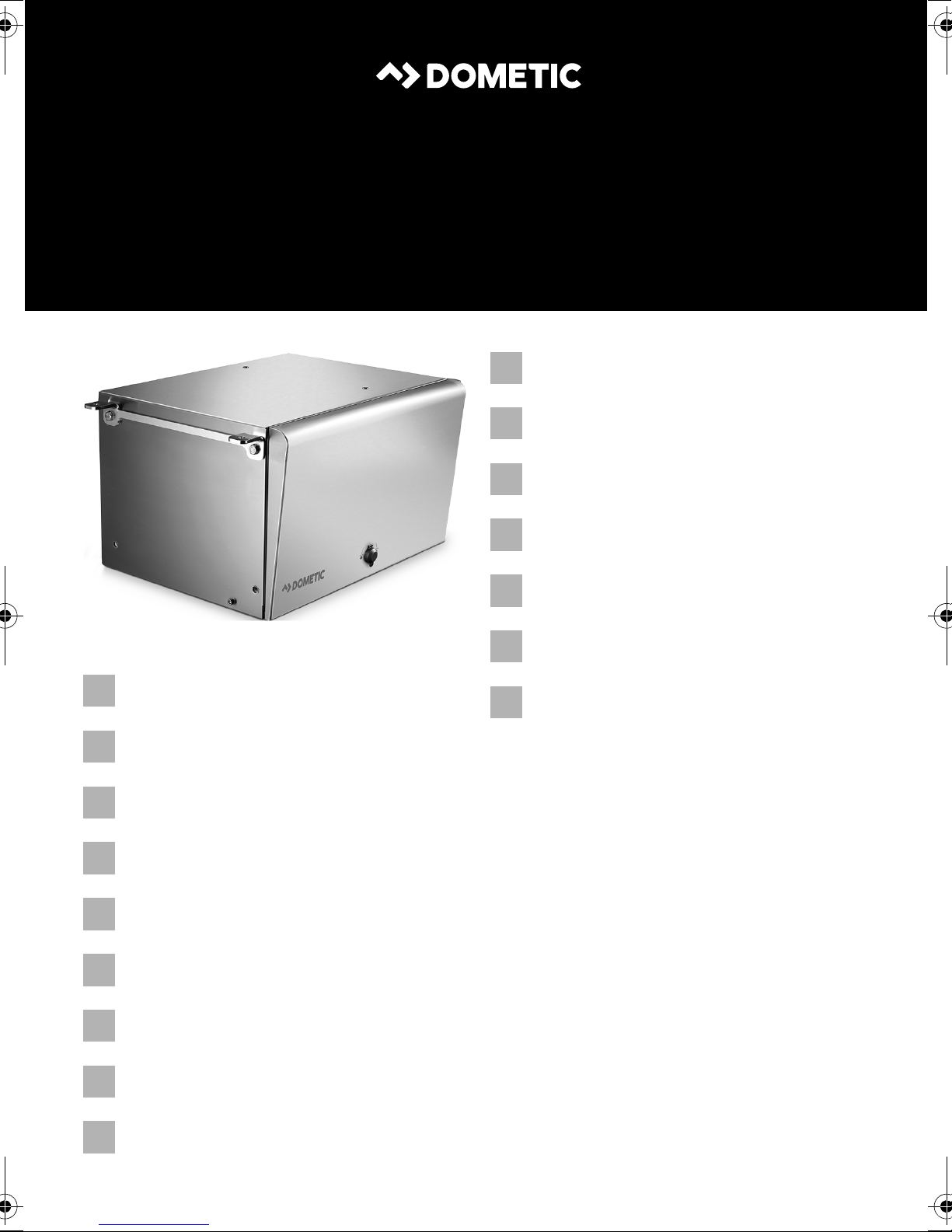
4Scope of delivery
No. in
fig. 1,
page 3
1 1 Generator
2 1 Remote control
3 1 Silencer
4 1 Exhaust pipe, 2 m
5 1 set Mounting brackets for silencer
6 1 set Retaining brackets for external installation
7 2 Holders for internal installation
8 4 Spacers
Number Description
9 1 Extension cable for remote control, 5 m
10 1 Hose clamp
11 1 Fuel filter
12 1 AG 128, seal
13 1 AG 102, changeover relay for making priority circuits
– 1 Battery charge controller
5Accessories
Available as accessories (not included in the scope of delivery):
Part designation Item number
AG 101, tank 15 l, plastic 9102900009
AG 100, tank 20 l, stainless steel 9102900011
AG 117, tank 15 l, plastic, with brackets and integrated mouth and cap 9102900010
AG 150, pipe set for AG 100 / AG 101 9102900003
AG 125, flexible metal pipe for extending exhaust pipe, 5 m 9102900138
AG 113, change over switch for parallel connection 9102900015
Parallel cable 9102900296
19
Page 20

EN
Intended use TEC29 EV, TEC29 EV LPG
6 Intended use
The TEC29 EV (reference no. 9102900299) and TEC29 EV LPG (reference no.
9102900302) generators are designed for use in motor homes, camper vans and
vehicles for commercial use.
The generator is not suitable for installation in water vessels.
The generator produces a pure sine wave voltage of 230 V/50 Hz which can be
connected to the consumer with a total continuous load of 2600 W. The power quality is also suitable for sensitive consumers (such as PCs).
The generator can charge a 12 V battery.
7Labels
A label is attached to the generator. This label provides the user and fitter with
information on the device specifications.
8 Technical description
Installing the generator must be configured according to one of the following
options:
• Automatic mode switch,
see chapter “Configuring the automatic mode” on page 29.
• Priority circuit which prioritises the 230 V external voltage over the voltage
produced by the generator,
see chapter “Creating a priority circuit” on page 30.
20
Page 21
EN
TEC29 EV, TEC29 EV LPG Installation
9Installation
CAUTION! Beware of injury
!
9.1 Note on installation
Read the installation manual carefully before you install the generator.
When installing the generator, note the following:
The generator may only be installed by qualified personnel from a specialist company. The following information is intended for technicians
who are familiar with the guidelines and safety precautions to be
applied.
DANGER! Danger of electrocution
Disconnect all power supplies when working on the generator.
D
CAUTION! Beware of injury
!
9.2 Securing the generator
Note on installation location
• Make sure that no combustible objects are stored or installed near the air outlet
or the ventilation slots. A distance of at least 50 cm should be kept.
• For a correct ventilation keep a distance of at least 30 cm from the generator's air
outlet.
• For safety reasons, note the location of existing wiring harnesses, wires and other
components within the installation area, in particular those which are not visible,
when installing the generator (when drilling or screwing etc.).
• Improper installation of the generator can result in irreparable damage to the device and put the safety of the user at risk.
• Always wear the recommended protective clothing (e.g. protective
goggles, gloves).
21
Page 22

EN
Installation TEC29 EV, TEC29 EV LPG
You can secure the generator with the holders supplied in two ways:
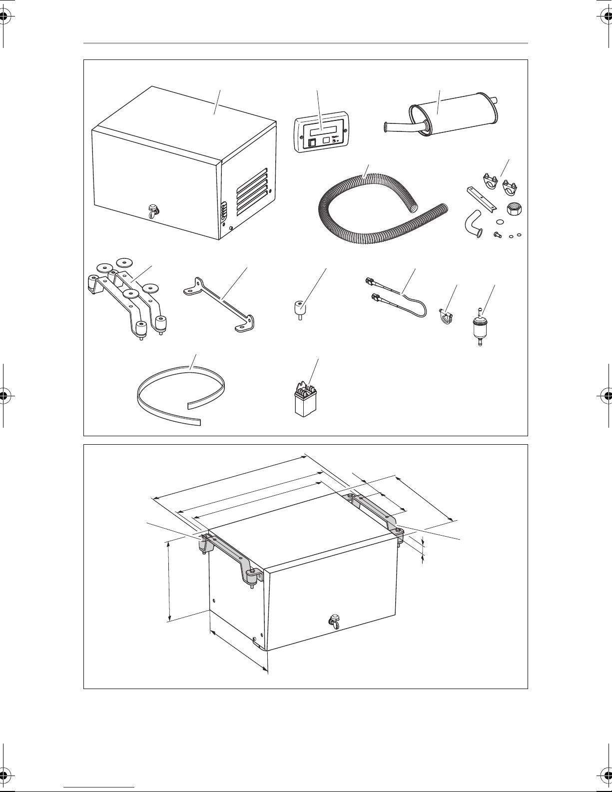
• External installation (fig. 2, page 3):
External installation has the following benefits: lower space requirement, fast
installation, easy access for maintenance work.
– To ensure the generator is attached securely, use the retaining bracket
(fig. 2 1, page 3) supplied.
– If the air intake opening of the generator is located behind a vehicle wheel,
you need to prevent the wheel from splashing any water into the generator
interior when it rains (e.g. by using a splash guard).
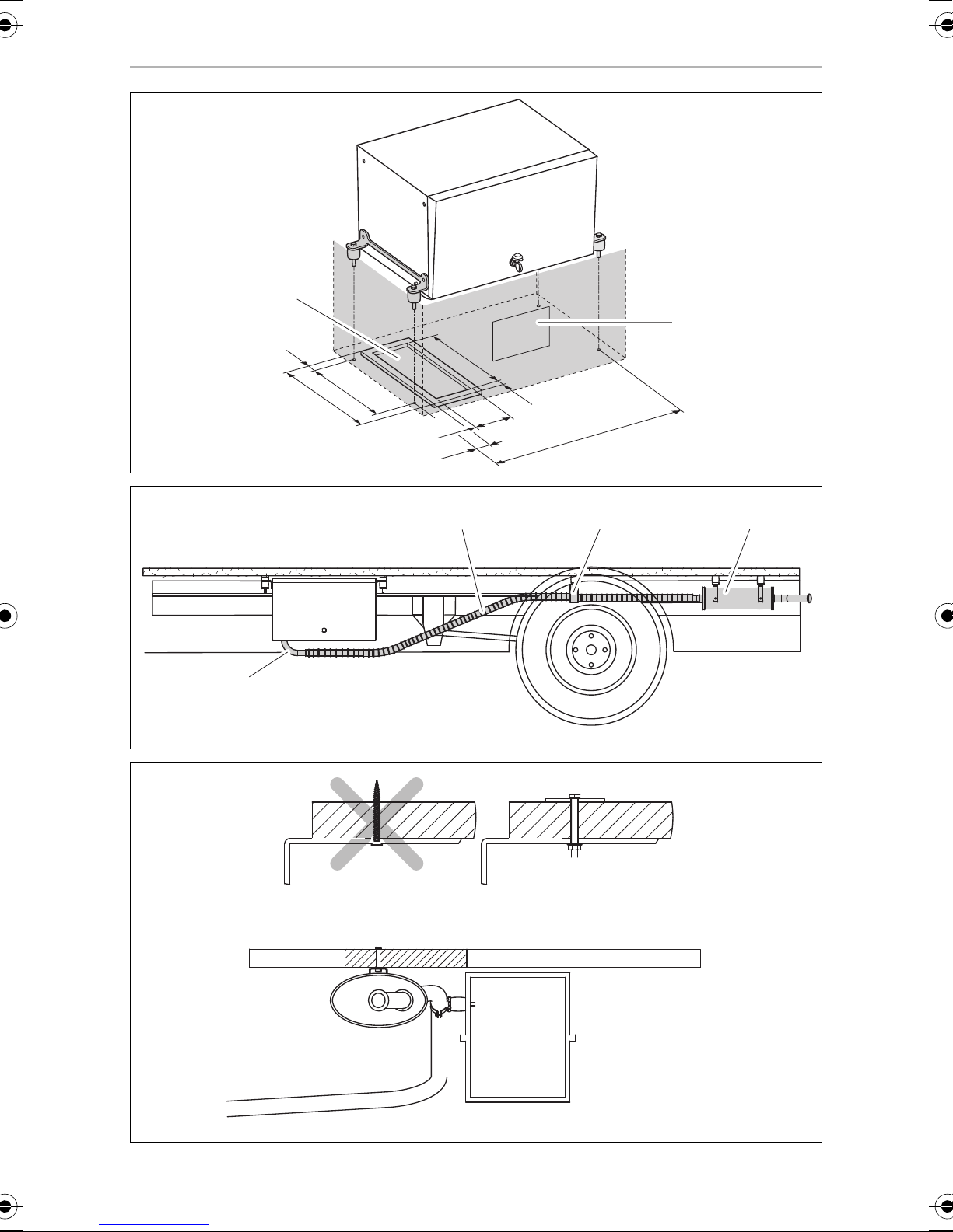
• Internal installation (fig. 3, page 4):
For internal installation, you need to prepare a sealed compartment against the
vehicle interior which can also be insulated against sound.
– Attach exhaust and air intake openings to the floor and in front of the
generator cover. The air intake openings must have cross-section of at least
240 cm
2
.
– You must also fit a seal (AG 128; available as an accessory) made of fire-retard-
ant rubber with a thickness of at least 5 mm between the floor of the vehicle
and the generator.
• Leave a space of at least 20 mm between the generator hood and surrounding
parts so that sufficient space remains for cooling air to pass through.
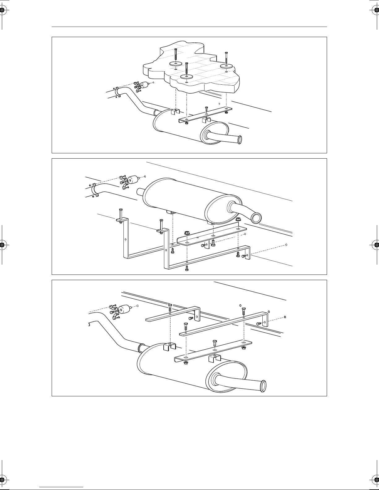
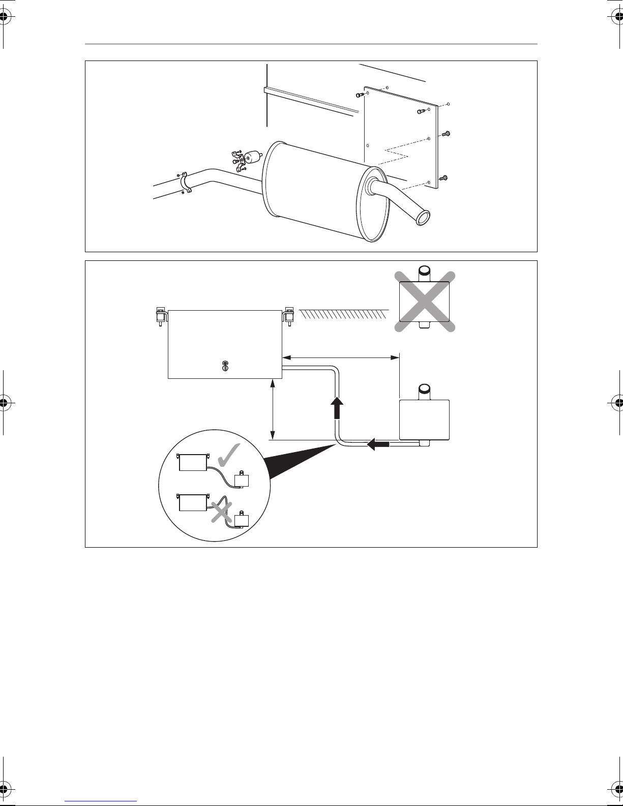
9.3 Securing the silencer
Observe the following instructions when installing the exhaust pipe:
• Do not create any sharp bends which will inhibit the flow of exhaust fumes.
• Align the manifold (fig. 4 1, page 4) along the housing to ensure greater
damping of vibration.
• Use the exhaust pipe extension to extent the exhaust pipe (fig. 4 2, page 4)
(see chapter “Accessories” on page 19).
Secure the extension to the vehicle floor (fig. 4 3, page 4).
➤ Secure the silencer (fig. 4 4, page 4) as in one of the alternatives shown in
fig. 5, page 4 to fig. 9, page 6.
22
Page 23
EN
TEC29 EV, TEC29 EV LPG Installation
9.4 TEC29 EV only: installing the tank and fuel supply line
Please observe the following instructions for the installation location:
• The tank bottom must be positioned at a maximum of 0.3 m below the bottom of
the generator.
• The top of the tank must not be higher than the top of the generator.
➤ Lay the fuel line as straight as possible.
➤ Secure the tank, see fig. 0, page 6 and chapter “TEC29 EV only: connecting
the float” on page 30.
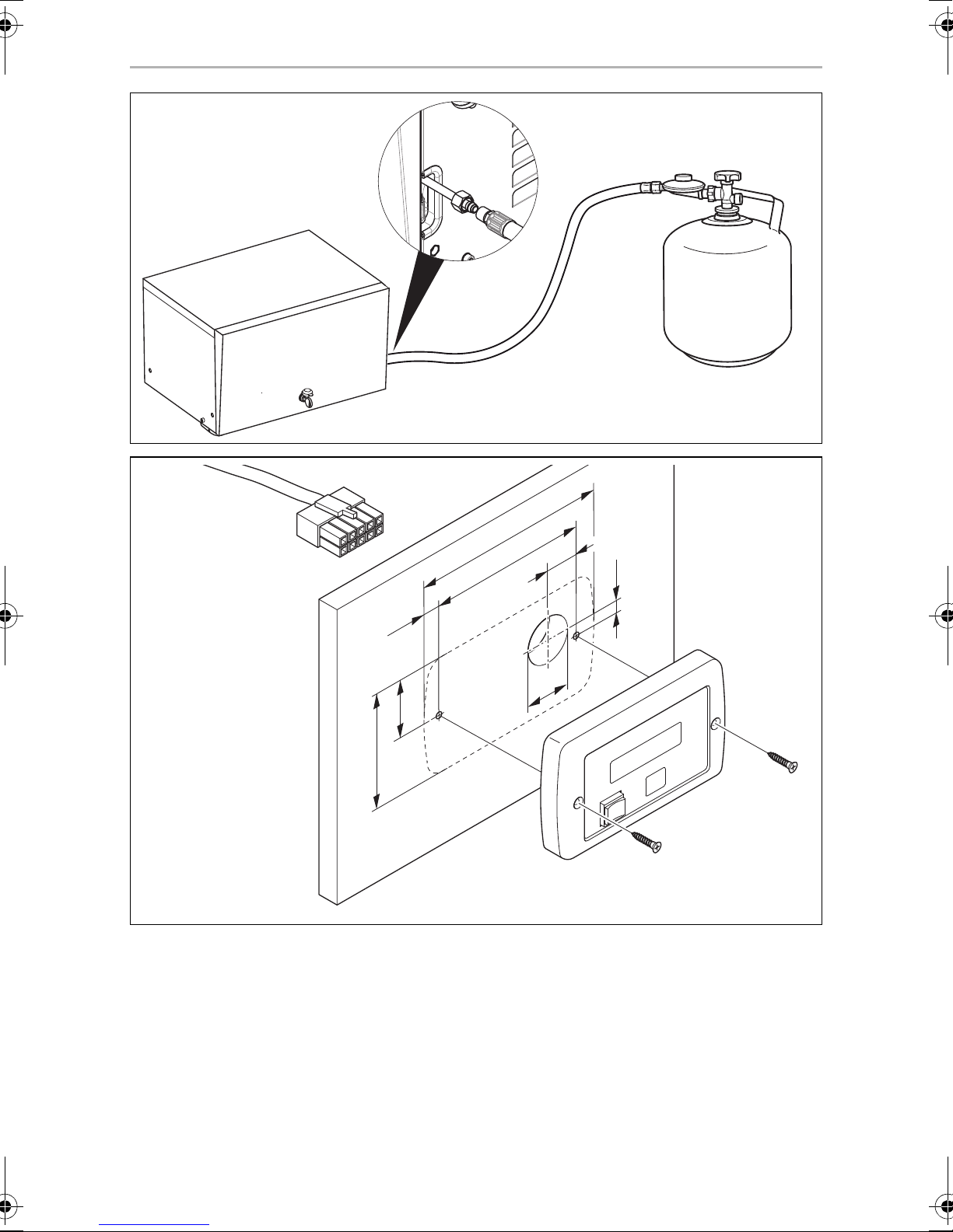
9.5 TEC29 EV LPG only: connecting the gas supply
The generator is connected to the low pressure regulator (30 millibar) of the LPG
cylinder.
➤ Lay the gas line using a suitable metal pipe.
➤ Connect the gas line as shown in fig. a, page 7.
9.6 Mounting the remote control
Please observe the following instructions for the installation location:
• Observe the length of the extension cable from the remote control to the
generator.
➤ Drill the holes as shown in fig. b, page 7.
➤ Insert the plug into the remote control.
➤ Screw on the remote control.
23
Page 24

EN
Connecting the electrical power to the generator TEC29 EV, TEC29 EV LPG
10 Connecting the electrical power to the
generator
DANGER! Danger of electrocution
D
Make sure there is no voltage at electrically operated components
before carrying out work on them!
NOTE
Observe the applicable guidelines in the country of the consumer.
I
10.1 Important notes on the electrical connection
• Only a qualified electrician should connect the generator to the electrical power.
• Check that the voltage specification on the type plate is the same as that of the
power supply.
• Do not lay the 230 Vw mains cable and the 12 Vg cable together in the same
cable duct.
• Do not lay cables which are loose or bent next to electrically conductive material
(metal).
• Connect the generator to a power circuit which can supply the necessary current
(see chapter “Technical data” on page 32).
• Select the cross-section of the cable as follows:
– 230 V: 2.5 mm²
– 12V battery charger: 2.5mm²
– Battery connection (length < 6 m): 10 mm²
– Battery connection (length > 6 m): 16 mm²
• Install a manual main switch which can disconnect all the consumers from the
generator with the exception of the battery.
24
Page 25
EN
TEC29 EV, TEC29 EV LPG Connecting the electrical power to the generator
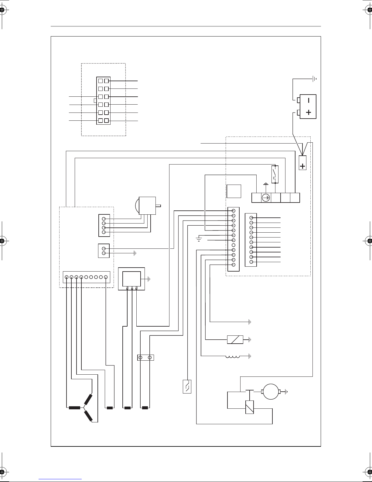
10.2 Circuit diagrams
TEC29 EV
The complete circuit diagram can be found in fig. c, page 8.
Item Description
1 3-phase winding
2 Auxiliary winding
3 Auxiliary winding
4Inverter
59-pin plug
6 Battery charger
7 Stepper motor
84-pin plug
9 Starter relay
10 Starter motor
11 Electromagnet for cold start
12 Oil level gauge
13 Motor coil
14 Internal control panel
15 Thermal disconnector
16 Interface module
17 Main switch
18 10-pin mini-fit plug
19 Battery positive terminal
20 Battery
21 2-pin mini-fit plug
22 Remote control
23 12-pin micro-fit plug
24 Auxiliary winding
25 2-pin plug connection
25
Page 26
EN
Connecting the electrical power to the generator TEC29 EV, TEC29 EV LPG
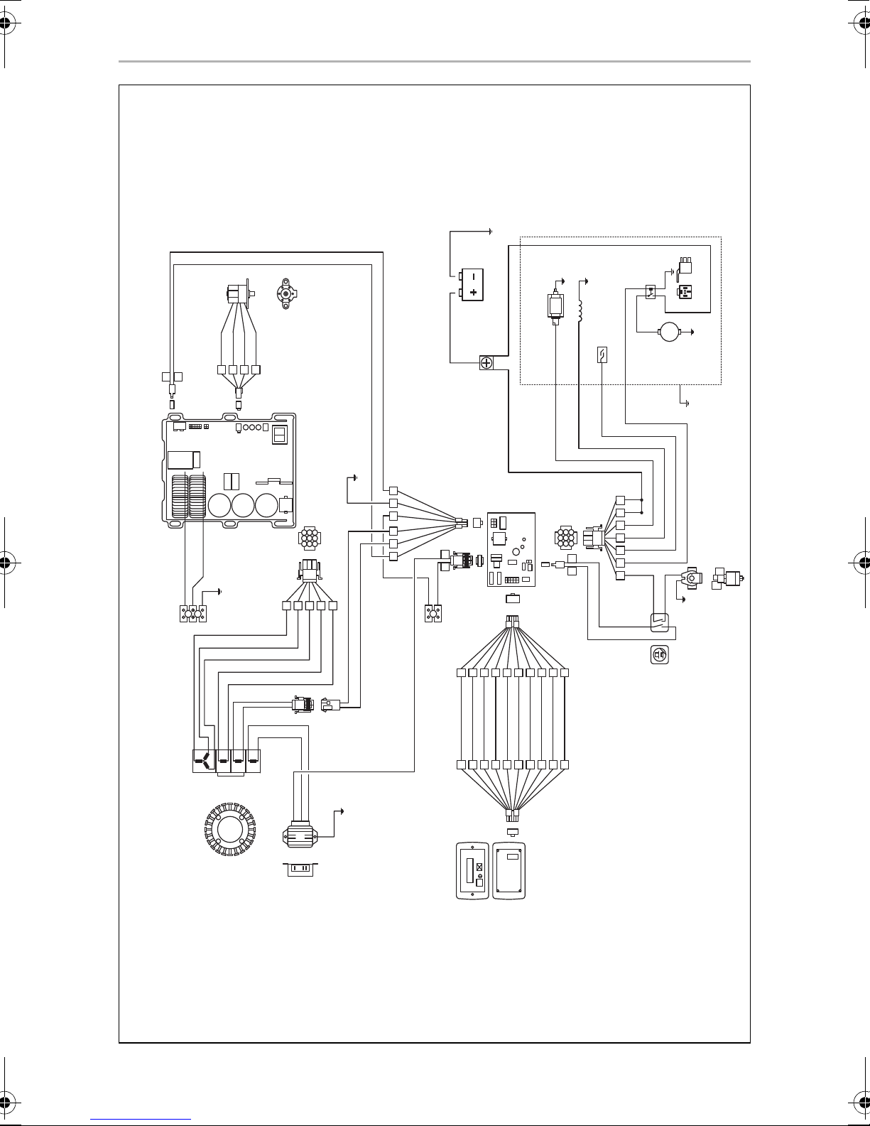
TEC29 EV LPG
The complete circuit diagram can be found in fig. d, page 9.
Item Description
1 3-phase winding
2 Auxiliary winding
3 Auxiliary winding
4Inverter
5 Starter relay
6 Battery charger
7 Main switch
8 Oil level gauge
9 Emergency stop switch
10 Starter motor
11 9-pin plug
12 Control unit
13 Motor coil
14 9-pin plug
15 Electromagnet for cold start
16 10-pin plug
17 Connection terminals
18 10-pin plug
19 Remote control
20 12-pin plug
21 Battery
22 Connection terminals
23 2-pin plug
24 4-pin plug
25 Stepper motor
26 6-pin plug
26
Page 27
EN
TEC29 EV, TEC29 EV LPG Connecting the electrical power to the generator
Item Description
27 2-pin plug
28 Battery positive terminal
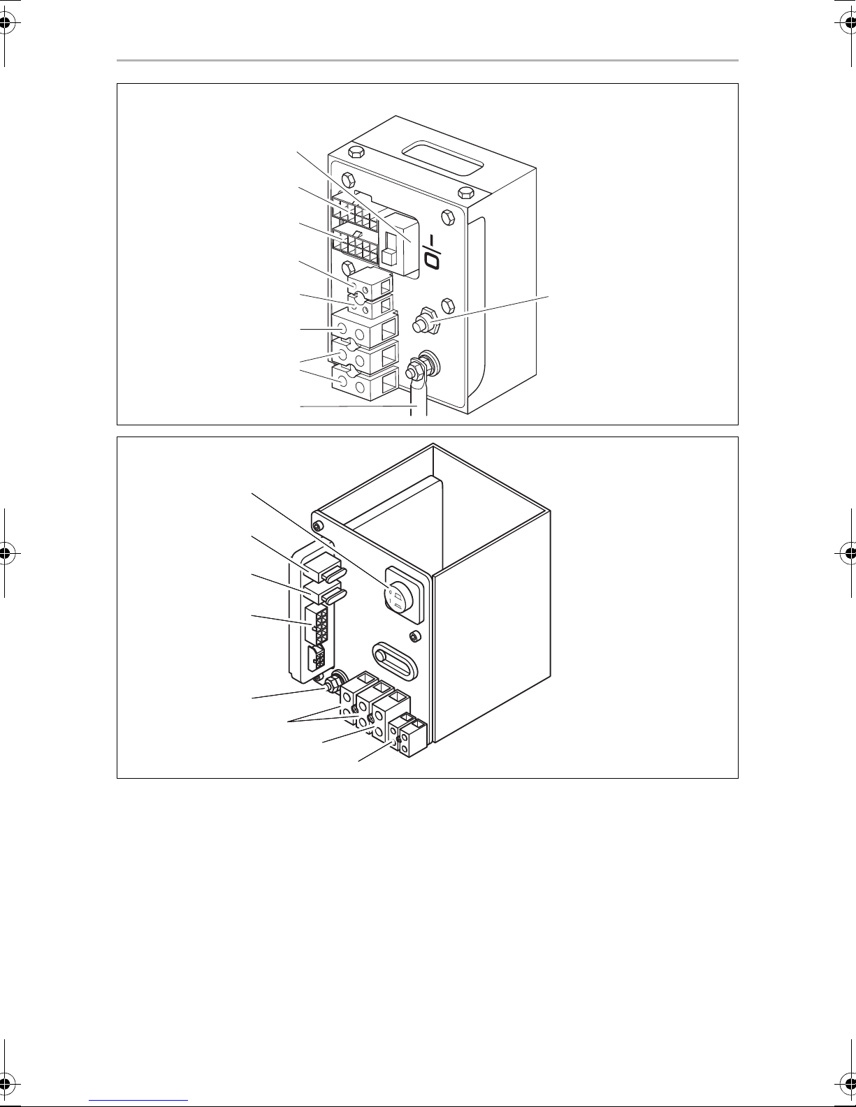
TEC29 EV control panel (fig. e, page 10)
Item Description
1 Main switch
2 Motor connection
3 Remote control connection
4 Float connection (petrol tank)
5 12 V battery charger connection
6 Earth
7 230 V connection
8 Battery positive terminal
9 Cut-out switch
TEC29 EV LPG control panel (fig. f, page 10)
Item Description
1 Main switch
2 Main fuse
3 Battery charger fuse
4 Remote control connection
5 Battery positive terminal
6 230 V connection
7 Earth
8 12 V battery charger connection
27
Page 28

EN
Connecting the electrical power to the generator TEC29 EV, TEC29 EV LPG
10.3 Connecting 230 V
NOTICE!
A
• Connect a relay or a switch to the vehicle’s electrical system so that
the generator is not damaged when the external mains is connected.
• Ensure that the electrical system is set up as follows:
–TN network:
The neutral conductor must be linked to the PE conductor on the
terminal via a jumper with a minimum diameter of 2.5 mm
protect against automatic shutdown, make sure that a safety
switch (FI switch, 30 mA) and an in all-pole overcurrent protection (e.g. circuit breaker, 13 A) are installed.
–IT network:
Ensure that an insulation monitor and an in all-pole overcurrent
protection (e.g. circuit breaker, 13 A) are installed.
• Connect the generator so that it takes priority over the power supply.
2
. To
➤ Guide the 230 V connection cable through the cable passage in the housing and
connect it to the 230 V terminals (for TEC29 EV: fig. e 7, page 10, for
TEC29 EVLPG: fig. f 6, page 10).
➤ Connect the earth cable to the earth connection on (for TEC29 EV: fig. e 6,
page 10, for TEC29 EVLPG: fig. f 7, page 10).
10.4 Connecting the battery charger
➤ Connect the positive terminal of the battery with the 12 V connection of the bat-
tery charger using a cable with a cross-section of 2.5 mm² (for TEC29 EV:
fig. e 5, page 10, for TEC29 EVLPG: fig. f 8, page 10).
➤ If the battery to be charged is not also the starter battery, connect the negative
terminal of the battery to be charged to the generator’s earth cable (fig. g 1,
page 11).
28
Page 29

EN
TEC29 EV, TEC29 EV LPG Connecting the electrical power to the generator
10.5 Connecting the starter battery
NOTICE!
The starter battery must have 12 V and a capacity of at least 60 Ah.
A
➤ Connect the positive terminal of the battery to the positive battery terminal
connection using a cable with a cross-section of 10 mm² for a length of < 6 m or
16 mm² for a length of > 6 m (for TEC29 EV: fig. e 8, page 10, for
TEC29 EVLPG: fig. f 5, page 10).
➤ Fit a 100 A fuse in the positive cable near the positive terminal of the starter
battery to protect the generator’s electrical system.
➤ Connect the negative terminal of the battery using a cable with a suitable cross-
section (see above) as follows:
– to the earth connection on the generator (fig. g 1, page 11) or
– via the inserts at the side of the generator (fig. g 2, page 11)
➤ Connect the earth connection on the generator to the vehicle chassis.
Remove any paint or rust from the chassis if necessary to ensure good contact.
➤ Protect the connections by applying lubrication.
10.6 Configuring the automatic mode
NOTE
I
• You can only use automatic mode:
– if the vehicle is stationary and the ignition is switched off
• To shorten charging times, an additional charging unit with at least
20 A can be installed between the generator and disconnector
switch, especially if batteries with a capacity of more than 60 Ah are
used.
• Make sure that one of the two instructions stickers provided is clearly
visible affixed next to the external control panel.
• Make sure that the second instructions sticker is affixed to the generators front door.
In automatic mode, the generator switches on automatically and charges the battery
if the voltage of the connected battery is too low.
The generator switches off automatically once the battery has been fully charged.
The circuit diagram for the automatic mode can be found in fig. h, page 11.
29
Page 30
EN
Connecting the electrical power to the generator TEC29 EV, TEC29 EV LPG
➤ Connect the black wire to terminal 6 of the 6-pin plug on the extension cable.
➤ Connect the black wire to switch 1 (not included in the scope of delivery).
➤ Lead the black wire from switch 1 to the ground through a connection managed
by the ignition key.
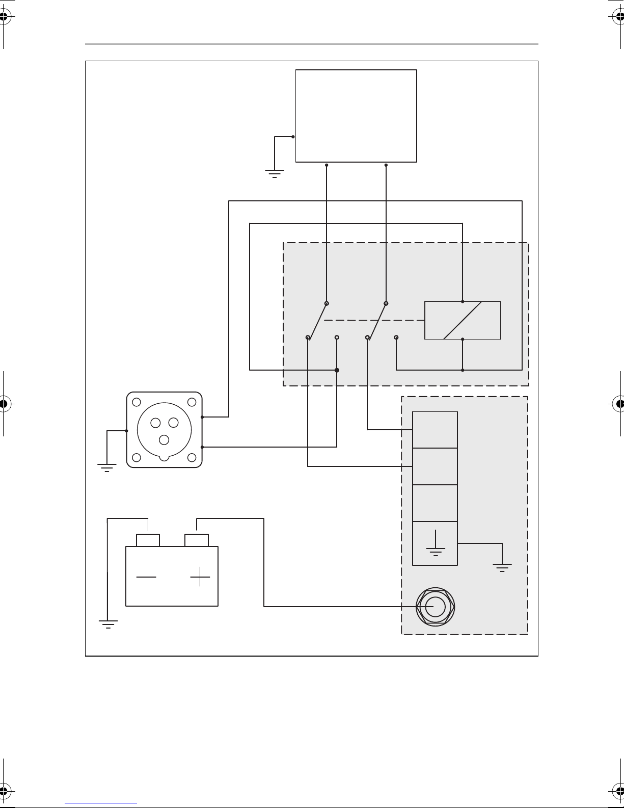
10.7 Creating a priority circuit
You can create a priority circuit using the AG 102 changeover relay whereby the
external voltage supply has priority over the generator, see circuit diagram (fig. i,
page 12):
Item Description
1 230 V external voltage supply
2 Vehicle electrical distribution system
3 Connection box
➤ Mount the AG 102 changeover relay in a suitable position.
➤ Disconnect the cable which links the mains input with the circuit breaker in the
electrical distribution system of the vehicle so that the connections can be made
as shown in the circuit diagram.
➤ Use a flat plug for connecting the cable to the switch.
➤ Connect A with plug-in sleeve 4 and B with plug-in sleeve 6.
➤ Connect the cable from the 230 V connection terminal of the generator to plug-
in sleeve 1 and plug-in sleeve 3.
10.8 Connecting the remote control
➤ Connect the remote control to the connection box of the generator using the
extension cable provided on the plug for the remote control (for TEC29 EV:
fig. e 3, page 10, for TEC29 EVLPG: fig. f 4, page 10).
10.9 TEC29 EV only: connecting the float
➤ Connect the float from the tank to the float connection (fig. e 4, page 10).
30
Page 31

EN
TEC29 EV, TEC29 EV LPG Connecting the electrical power to the generator
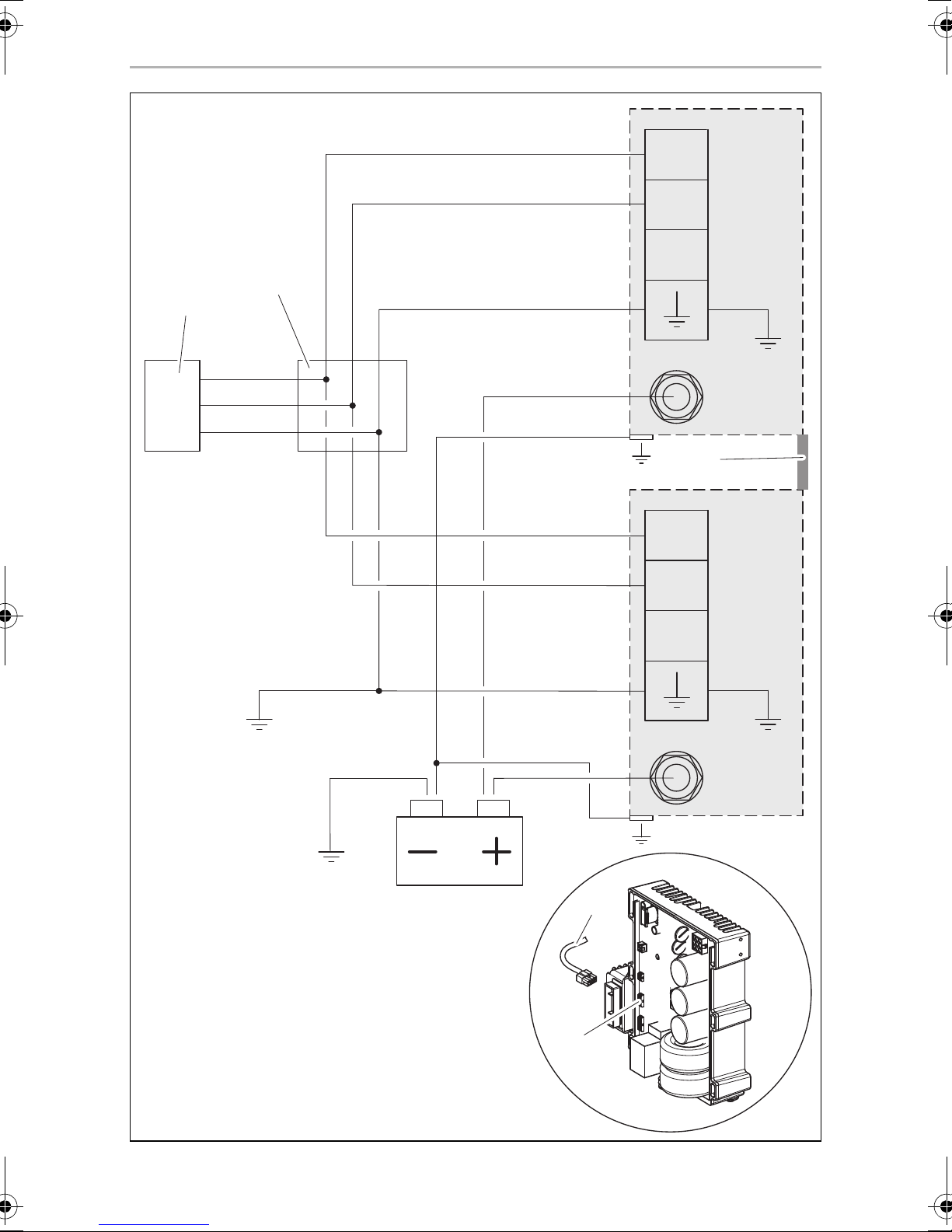
10.10 Connecting two genarators in parallel
NOTE
Use only one starter battery to start both generators.
I
When connecting the generators, note the following:
• It is not possible to connect more than two generators in parallel.
• To start one generator at a time the starter battery capacity has to be according
to the generator manual (minimum capacity: 60 Ah).
To start both generators at the same time you have to double the battery
capacity.
• The cross section of the battery connection cable for each generator has to be at
least:
– 10 mm² if the total length is less than 6 m
– 16 mm² if the total length is more than 6 m
NOTE
I
Proceed as follows (fig. j, page 13):
➤ Connect each generator to a junction box (1; not included in the scope of
delivery).
The minimum cross section for each generator output cable is 2.5 mm².
➤ Create a single output for the load (2) inside the junction box (1).
The minimum cross section for the parallel output cable is 6 mm².
➤ Connect the battery‘s negative pole to ground.
➤ Connect the output ground cable to ground.
➤ Connect the change over switch AG 113 (available as accessory) between the
junction box and the load.
• The maximum distance between each generator to the junction box
is 15 m.
• The maximum length difference between the output cables of the
generators must be 2 m.
➤ To properly run the generators in parallel connect the inverters (4) of each
genarator using the parallel cable (3; available as accessory).
31
Page 32

EN
Disposal TEC29 EV, TEC29 EV LPG
11 Disposal
➤ Place the packaging material in the appropriate recycling waste bins wherever
possible.
If you wish to finally dispose of the product, ask your local recycling centre
or specialist dealer for details about how to do this in accordance with the
M
applicable disposal regulations.
12 Technical data
Dometic TEC29 EV Dometic TEC29 EV LPG
Reference no.: 9102900299 9102900302
Rated output voltage: 230 Vw / 50 Hz
Max. constant output
(at 25 °C at sea level):
Battery charger output voltage: 12 V g
Battery charger max. output
current:
Operating temperature range: –15 °C to +50 °C –15 °C to +50 °C
Distortion factor: 1 %
Fuel: RON 91 regular grade
petrol
Consumption: 300 g/kWh
max. 1.2 l/h
Motor output: 4.0 kW (5.5 PS)
Guaranteed sound level: 86 dB(A)
2600 W
10 A
(depending on propane
content of LPG)
Liquid gas LPG
408 g/kWh
max. 1.0 kg/h
Sound level at distance of 7 m: 54 – 59 dB(A)
Dimensions: see fig. 2, page 3
Weight: 44 kg
32
Page 33

DE
TEC29 EV, TEC29 EV LPG
Bitte lesen Sie diese Anleitung vor Einbau und Inbetriebnahme sorgfältig
durch und bewahren Sie sie auf. Geben Sie sie im Falle einer Weitergabe
des Produktes an den Nutzer weiter.
Inhaltsverzeichnis
1 Erklärung der Symbole . . . . . . . . . . . . . . . . . . . . . . . . . . . . . . . . . . . . . . . . . 34
2 Sicherheits- und Einbauhinweise . . . . . . . . . . . . . . . . . . . . . . . . . . . . . . . . . 34
3 Zielgruppe dieser Anleitung . . . . . . . . . . . . . . . . . . . . . . . . . . . . . . . . . . . . 36
4 Lieferumfang . . . . . . . . . . . . . . . . . . . . . . . . . . . . . . . . . . . . . . . . . . . . . . . . . 37
5 Zubehör. . . . . . . . . . . . . . . . . . . . . . . . . . . . . . . . . . . . . . . . . . . . . . . . . . . . . 38
6 Bestimmungsgemäßer Gebrauch . . . . . . . . . . . . . . . . . . . . . . . . . . . . . . . . 38
7 Kennzeichnungsschilder . . . . . . . . . . . . . . . . . . . . . . . . . . . . . . . . . . . . . . . 38
8 Technische Beschreibung . . . . . . . . . . . . . . . . . . . . . . . . . . . . . . . . . . . . . . 39
9 Montage . . . . . . . . . . . . . . . . . . . . . . . . . . . . . . . . . . . . . . . . . . . . . . . . . . . . 39
10 Generator elektrisch anschließen. . . . . . . . . . . . . . . . . . . . . . . . . . . . . . . . . 42
11 Entsorgung . . . . . . . . . . . . . . . . . . . . . . . . . . . . . . . . . . . . . . . . . . . . . . . . . . .51
12 Technische Daten . . . . . . . . . . . . . . . . . . . . . . . . . . . . . . . . . . . . . . . . . . . . . .51
33
Page 34

DE
Erklärung der Symbole TEC29 EV, TEC29 EV LPG
1 Erklärung der Symbole
GEFAHR!
D
!
Sicherheitshinweis: Nichtbeachtung führt zu Tod oder schwerer
Verletzung.
WARNUNG!
Sicherheitshinweis: Nichtbeachtung kann zu Tod oder schwerer
Verletzung führen.
VORSICHT!
Sicherheitshinweis: Nichtbeachtung kann zu Verletzungen führen.
!
ACHTUNG!
A
Nichtbeachtung kann zu Materialschäden führen und die Funktion des
Produktes beeinträchtigen.
HINWEIS
Ergänzende Informationen zur Bedienung des Produktes.
I
2 Sicherheits- und Einbauhinweise
Beachten Sie die vom Fahrzeughersteller und vom Kfz-Handwerk vorgeschriebenen Sicherheitshinweise und Auflagen!
Der Hersteller übernimmt in folgenden Fällen keine Haftung für Schäden:
• Montage- oder Anschlussfehler
• Beschädigungen am Produkt durch mechanische Einflüsse und Über-
spannungen
• Veränderungen am Produkt ohne ausdrückliche Genehmigung vom Hersteller
• Verwendung für andere als die in der Anleitung beschriebenen Zwecke
Beachten Sie folgende grundsätzliche Sicherheitsmaßnahmen beim Gebrauch von
elektrischen Geräten zum Schutz vor:
• elektrischem Schlag
• Brandgefahr
• Verletzungen
34
Page 35

DE
TEC29 EV, TEC29 EV LPG Sicherheits- und Einbauhinweise
2.1 Umgang mit dem Gerät
WARNUNG!
!
• Die Montage und Reparaturen des Generators dürfen nur von Fach-
kräften durchgeführt werden, die mit den verbundenen Gefahren
bzw. den einschlägigen Vorschriften vertraut sind. Durch unsachgemäße Reparaturen können erhebliche Gefahren entstehen. Wenden
Sie sich im Reparaturfall an den Service-Stützpunkt in Ihrem Land
(Adressen auf der Rückseite).
• Elektrogeräte sind kein Kinderspielzeug!
Kinder können Gefahren, die von elektrischen Geräten ausgehen,
nicht richtig einschätzen. Lassen Sie Kinder nicht ohne Aufsicht elektrische Geräte benutzen.
• Personen (einschließlich Kinder), die aufgrund ihrer physischen, sensorischen oder geistigen Fähigkeiten oder ihrer Unerfahrenheit oder
Unkenntnis nicht in der Lage sind, das Gerät sicher zu benutzen, sollten dieses Gerät nicht ohne Aufsicht oder Anweisung durch eine verantwortliche Person nutzen.
• Die Abgase enthalten Kohlenmonoxid, ein äußerst giftiges, geruchloses und farbloses Gas. Atmen Sie die Abgase nicht ein. Lassen Sie
den Motor des Generators nicht in einer geschlossenen Garage oder
in einem fensterlosen Raum laufen.
!
VORSICHT!
• Brandgefahr!
Montieren Sie den Generator nicht in Kisten oder Räumen ohne Öffnungen, sondern in ausreichend belüfteten Bereichen oder Räumen.
• Betreiben Sie den Generator nur, wenn das Gehäuse und die
Leitungen unbeschädigt sind.
• Montieren Sie den Generator auf stabilem Untergrund.
• Neigen Sie den Generator nicht um mehr als 20° gegen die Senk-
rechte.
35
Page 36

DE
Zielgruppe dieser Anleitung TEC29 EV, TEC29 EV LPG
ACHTUNG!
A
2.2 Umgang mit elektrischen Leitungen
!
!
• Benutzen Sie das Gerät nur zu seinem bestimmungsgemäßen
Gebrauch.
• Der Generator ist nicht für den Betrieb in Wasserfahrzeugen geeignet.
• Führen Sie keine Änderungen oder Umbauten am Gerät durch.
• Wenn Schweißarbeiten am Fahrzeug durchgeführt werden müssen,
trennen Sie alle Kabel zum Generator; sonst kann die Elekronik
beschädigt werden.
WARNUNG!
• Der elektrische Anschluss darf nur von einem Fachbetrieb durchgeführt werden (z. B. in Deutschland nach VDE 0100, Teil 721).
VORSICHT!
• Befestigen und verlegen Sie Leitungen so, dass keine Stolpergefahr
entsteht und eine Beschädigung des Kabels ausgeschlossen ist.
ACHTUNG!
A
• Müssen Leitungen durch scharfkantige Wände geführt werden, so
verwenden Sie Leerrohre bzw. Leitungsdurchführungen.
• Verlegen Sie keine losen oder scharf abgeknickten Leitungen an elektrisch leitenden Materialien (Metall).
• Ziehen Sie nicht an Leitungen.
3 Zielgruppe dieser Anleitung
Diese Anleitung richtet sich an Facharbeiter in Werkstätten, die mit den anzuwendenden Richtlinien und Sicherheitsvorkehrungen vertraut sind.
36
Page 37

DE
TEC29 EV, TEC29 EV LPG Lieferumfang
4 Lieferumfang
Pos. in
Abb. 1,
Seite 3
1 1 Generator
2 1 Fernbedienung
3 1 Schalldämpfer
4 1 Abgasleitung, 2 m
5 1 Satz Befestigungswinkel für den Schalldämpfer
6 1 Satz Haltebügel zur Außenmontage
7 2 Halterungen zur Innenmontage
8 4 Abstandhalter
Anzahl Bezeichnung
9 1 Verlängerungskabel für die Fernbedienung, 5 m
10 1 Schlauchschelle
11 1 Kraftstofffilter
12 1 AG 128, Dichtung
13 1 AG 102, Umschaltrelais zur Realisierung einer Vorrang-
schaltung
– 1 Batterie-Laderegler
37
Page 38

DE
Zubehör TEC29 EV, TEC29 EV LPG
5Zubehör
Als Zubehör erhältlich (nicht im Lieferumfang enthalten):
Teilebezeichnung Artikelnummer
AG 101, Tank 15 l, Kunststoff 9102900009
AG 100, Tank 20 l, Edelstahl 9102900011
AG 150, Schlauch-Set für AG 100 / AG 101 9102900003
AG 117, Tank 15 l, Kunststoff, mit Befestigungsbügeln sowie integriertem Ausguss und intergrierter Verschlusskappe
AG 125, flexibler Metallschlauch zur Verlängerung der Abgasleitung,
5m
AG 113, Umschalter für Parallelschaltungen 9102900015
Parallelkabel 9102900296
9102900010
9102900138
6 Bestimmungsgemäßer Gebrauch
Die Generatoren TEC29 EV (Art.-Nr. 9102900299) und TEC29 EV LPG (Art.-Nr.
9102900302
und kommerziell genutzten Fahrzeugen.
Der Generator ist nicht für die Installation in Wasserfahrzeugen geeignet.
Der Generator erzeugt eine reine Sinus-Wechselspannung von 230 V/50 Hz, an die
Verbraucher mit einer Gesamtdauerlast von 2600 W angeschlossen werden können. Die Stromqualität ist auch für empfindliche Verbraucher (z. B. PCs) geeignet.
) sind ausgelegt für die Verwendung in Wohnwagen, Wohnmobilen
Der Generator kann eine 12-V-Batterie aufladen.
7 Kennzeichnungsschilder
Am Generator ist ein Kennzeichnungsschild angebracht. Dieses Kennzeichnungsschild informiert den Anwender und den Installateur über Gerätespezifikationen.
38
Page 39

DE
TEC29 EV, TEC29 EV LPG Technische Beschreibung
8 Technische Beschreibung
Der Generator bietet folgende Möglichkeiten, die beim Einbau entsprechend konfiguriert werden müssen:
• Automatikbetrieb-Schalter,
siehe Kapitel „Automatikbetrieb konfigurieren“ auf Seite 48.
• Vorrangschaltung, mit der die externe 230 V Spannung Vorrang vor der durch
den Generator erzeugten Spannung hat,
siehe Kapitel „Vorrangschaltung realisieren“ auf Seite 49.
9Montage
VORSICHT! Verletzungsgefahr!
!
Die Montage des Generators darf ausschließlich von entsprechend ausgebildeten Fachbetrieben durchgeführt werden. Die nachfolgenden
Informationen richten sich an Fachkräfte, die mit den anzuwendenden
Richtlinien und Sicherheitsvorkehrungen vertraut sind.
9.1 Hinweise zur Montage
Lesen Sie diese Montageanleitung vor der Montage des Generators vollständig.
Beachten Sie bei der Montage des Generators folgende Hinweise:
GEFAHR! Lebensgefahr durch Stromschlag!
D
!
Unterbrechen Sie bei Arbeiten am Generator alle Spannungsversorgungen.
VORSICHT! Verletzungsgefahr!
• Eine falsche Montage des Generators kann zu irreparablen Schäden
am Gerät führen und die Sicherheit des Benutzers beeinträchtigen.
• Tragen Sie bei allen Arbeiten die vorgeschriebene Schutzbekleidung (z. B. Schutzbrille, Schutzhandschuhe).
39
Page 40

DE
Montage TEC29 EV, TEC29 EV LPG
9.2 Generator befestigen
Hinweise zum Montageort
• Achten Sie darauf, dass keine brennbare Gegenstände im Bereich des Auspuffs
oder der Lüftungslamellen gelagert oder montiert sind. Der Abstand sollte mindestens 50 cm betragen.
• Halten Sie mindestens einen Abstand von 30 cm zum Luftauslass des Generator,
um eine ordnungsgemäße Belüftung zu gewährleisten.
• Achten Sie aus Sicherheitsgründen beim Einbau des Generators (beim Bohren
und Schrauben usw.) auf den Verlauf von vorhandenen, insbesondere nicht
sichtbaren Kabelsträngen, Leitungen und anderen Komponenten, die sich im
Montagebereich befinden!
Sie können den Generator mit den mitgelieferten Halterungen auf zwei Arten befestigen:
• Außenmontage (Abb. 2, Seite 3):
Die Außenmontage bietet folgende Vorteile: geringerer Platzbedarf, schnelle
Installation, leichter Zugang für Wartungsarbeiten.
– Um eine solide Befestigung des Generators zu gewährleisten, müssen Sie die
mitgelieferten Haltebügel (Abb. 2 1, Seite 3) verwenden.
– Falls die Luftansaugöffnung des Generator hinter einem Rad des Fahrzeugs
liegt, müssen Sie verhindern, dass das Rad bei Regen Wasser in das Innere
des Generators schleudert (z. B. durch einen Spritzschutz).
• Innenmontage (Abb. 3, Seite 4):
Für die Innenmontage müssen Sie einen gegen das Fahrzeuginnere abgedichteten Raum vorbereiten, den Sie zusätzlich gegen Schall isolieren können.
– Sie müssen auf dem Boden und vor der Generatorklappe Auspuff- und
Luftansaugöffnungen anbringen. Die Luftansaugöffnungen müssen einen
Querschnitt von mindestens 240 cm
2
haben.
– Zusätzlich müssen Sie eine Dichtung (AG 128; als Zubehör erhältlich) aus
brandhemmendem Gummi mit einer Dicke von mindestens 5 mm zwischen
dem Boden des Fahrzeugs und dem Generator anbringen.
• Lassen Sie mindestens 20 mm freien Platz zwischen der Haube des Generators
und den umgebenden Teilen, so dass genügend Platz für das Durchströmen der
Kühlungsluft bleibt.
40
Page 41

DE
TEC29 EV, TEC29 EV LPG Montage
9.3 Schalldämpfer befestigen
Beachten Sie folgende Hinweise beim Verlegen der Abgasleitung:
• Erzeugen Sie keine scharfen Kurven, die den Strom der Abgase behindern.
• Richten Sie den Krümmer (Abb. 4 1, Seite 4) längs des Gehäuses aus, um eine
stärkere Dämpfung der Vibrationen zu gewährleisten.
• Verwenden Sie zum Umlenken der Auspuffgase die Verlängerung der Abgasleitung (Abb. 4 2, Seite 4) (siehe Kapitel „Zubehör“ auf Seite 38).
Befestigen Sie die Verlängerung am Fahrzeugboden (Abb. 4 3, Seite 4).
➤ Befestigen Sie den Schalldämpfer (Abb. 4 4, Seite 4) auf eine der in Abb. 5,
Seite 4 bis Abb. 9, Seite 6 gezeigten Alternativen.
9.4 Nur TEC29 EV: Tank und Kraftstoffleitung montieren
Beachten Sie folgende Hinweise zum Montageort:
• Der Tankboden darf sich maximal 0,3 m unterhalb des Bodens des Generators
befinden.
• Die Tankoberkante darf nicht über der Oberkante des Generators liegen.
➤ Verlegen Sie die Kraftstoffleitung möglichst gerade.
➤ Befestigen Sie den Tank, siehe Abb. 0, Seite 6 und Kapitel „Nur TEC29 EV:
Schwimmer anschließen“ auf Seite 49.
9.5 Nur TEC29 EV LPG: Gasversorgung anschließen
Der Generator wird an den Niederdruckregler (30 mbar, minimale Durchflussmenge 1,2 kg/Stunde) der LPG-Flasche angeschlossen.
➤ Verlegen Sie die Gasleitung mit geeigneten Metallrohren.
➤ Schließen Sie die Gasleitung wie in Abb. a, Seite 7 gezeigt an.
41
Page 42

DE
Generator elektrisch anschließen TEC29 EV, TEC29 EV LPG
9.6 Fernbedienung montieren
Beachten Sie folgenden Hinweis zum Montageort:
• Beachten Sie die Länge des Verlängerungskabels von der Fernbedienung zum
Generator.
➤ Bohren Sie die Löcher wie in Abb. b, Seite 7 gezeigt.
➤ Stecken Sie den Stecker in die Fernbedienung ein.
➤ Schrauben Sie die Fernbedienung an.
10 Generator elektrisch anschließen
GEFAHR! Lebensgefahr durch Stromschlag!
D
Vor Arbeiten an elektrisch betriebenen Komponenten ist sicherzustellen, dass keine Spannung mehr anliegt!
HINWEIS
Beachten Sie die geltenden Richtlinien im Land des Verbrauchers.
I
10.1 Wichtige Hinweise zum elektrischen Anschluss
• Lassen Sie den Generator nur von einer Fachkraft elektrisch anschließen.
• Vergleichen Sie die Spannungsangabe auf dem Typenschild mit der vorhande-
nen Energieversorgung.
• Verlegen Sie 230-Vw-Leitungen und 12-Vg-Leitungen nicht zusammen im gleichen Leitungskanal (Leerrohr).
• Verlegen Sie Leitungen nicht lose oder scharf abgeknickt an elektrisch leitenden
Materialien (Metall).
• Schließen Sie den Generator an einen Stromkreis an, der in der Lage ist, den
erforderlichen Strom zu liefern (siehe Kapitel „Technische Daten“ auf Seite 51).
• Wählen Sie den Leitungsquerschnitt wie folgt:
– 230 V: 2,5 mm²
– 12 V Batterielader: 2,5 mm²
– Batterieanschluss (Länge < 6 m): 10 mm²
– Batterieanschluss (Länge > 6 m): 16 mm²
• Installieren Sie einen manuellen Hauptschalter, mit dem alle eingeschalteten Verbraucher mit Ausnahme der Batterie vom Generator getrennt werden können.
42
Page 43

DE
TEC29 EV, TEC29 EV LPG Generator elektrisch anschließen
10.2 Schaltpläne
TEC29 EV
Den Gesamtschaltplan finden Sie in Abb. c, Seite 8:
Pos. Beschreibung
1 3-Phasen-Wicklung
2 Hilfswicklung
3 Hilfswicklung
4Inverter
5 9-poliger Stecker
6 Batterielader
7 Schrittmotor
8 4-poliger Stecker
9 Starterrelais
10 Anlassermotor
11 Elektromagnet für Kaltstart
12 Ölstandmelder
13 Motorspule
14 Anschlusspanel
15 Thermischer Lasttrennschalter
16 Schnittstellenmodul
17 Hauptschalter
18 10-poliger Mini-Fit-Stecker
19 Anschlussklemme Batterie-Pluspol
20 Batterie
21 2-poliger Mini-Fit-Stecker
22 Fernbedienung
23 12-poliger Micro-Fit-Stecker
24 Hilfswicklung
25 2-poliger Steckverbinder
43
Page 44

DE
Generator elektrisch anschließen TEC29 EV, TEC29 EV LPG
TEC29 EVLPG
Den Gesamtschaltplan finden Sie in Abb. d, Seite 9:
Pos. Beschreibung
1 3-Phasen-Wicklung
2 Hilfswicklung
3 Hilfswicklung
4Inverter
5 Starterrelais
6 Batterielader
7 Hauptschalter
8 Ölstandmelder
9 Not-Aus-Schalter
10 Anlassermotor
11 9-poliger Stecker
12 Steuerplatine
13 Motorspule
14 9-poliger Stecker
15 Elektromagnet für Kaltstart
16 10-poliger Stecker
17 Anschlussklemmen
18 10-poliger Stecker
19 Fernbedienung
20 12-poliger Stecker
21 Batterie
22 Anschlussklemmen
23 2-poliger Stecker
24 4-poliger Stecker
25 Schrittmotor
26 6-poliger Stecker
44
Page 45

DE
TEC29 EV, TEC29 EV LPG Generator elektrisch anschließen
Pos. Beschreibung
27 2-poliger Stecker
28 Anschlussklemme Batterie-Pluspol
TEC29 EV Anschlusspanel (Abb. e, Seite 10)
Pos. Beschreibung
1 Hauptschalter
2 Motoranschluss (D+-Signal)
3 Fernbedienungsanschluss
4 Schwimmeranschluss (Benzintank)
5 12-V-Anschluss des Batterieladers
6 Masse
7 230-V-Anschluss
8 Anschlussklemme Batterie-Pluspol
9 Schutzschalter
TEC29 EV LPG Anschlusspanel (Abb. f, Seite 10)
Pos. Beschreibung
1 Hauptschalter
2 Hauptsicherung
3 Sicherung Batterielader
4 Fernbedienungsanschluss
5 Anschlussklemme Batterie-Pluspol
6 230-V-Anschluss
7 Masse
8 12-V-Anschluss des Batterieladers
45
Page 46

DE
Generator elektrisch anschließen TEC29 EV, TEC29 EV LPG
10.3 230 V anschließen
ACHTUNG!
A
• Schließen Sie an der Elektroanlage des Fahrzeugs ein Relais oder
einen Umschalter an, damit der Generator nicht beschädigt wird,
wenn das externe Stromnetz angeschlossen wird.
• Stellen Sie sicher, dass die elektrische Anlage folgendermaßen eingerichtet ist:
– TN-Netz:
Der Neutralleiter muss mit dem Schutzleiter PE an der Anschlussklemme über eine Drahtbrücke mit einem Mindestquerschnitt
von 2,5 mm
vor automatischer Abschaltung ein Personenschutzschalter
(FI-Schalter, 30 mA) und ein allpolig wirkender Überstromschutz
(z. B. Leistungsschutzschalter, 13 A) installiert sind.
–IT-Netz:
Stellen Sie sicher, dass ein Isolationswächter und ein allpolig wirkender Überstromschutz (z. B. Leistungsschutzschalter, 13 A) installiert sind.
• Schließen Sie den Generator möglichst so an, dass er Priorität
gegenüber dem Stromnetz besitzt.
2
gebrückt sein. Stellen Sie sicher, dass zum Schutz
➤ Führen Sie das 230-V-Anschlusskabel durch den Kabeldurchgang in das
Gehäuse, und schließen Sie es an den 230-V-Klemmen (für TEC29 EV:
Abb. e 7, Seite 10, für TEC29 EVLPG: Abb. f 6, Seite 10) an.
➤ Schließen Sie das Erdungskabel am Masseanschluss an (für TEC29 EV:
Abb. e 6, Seite 10, für TEC29 EVLPG: Abb. f 7, Seite 10).
10.4 Batterielader anschließen
➤ Verbinden Sie den Pluspol der Batterie mit einem Kabel mit einem Querschnitt
von 2,5 mm² mit dem 12-V-Anschluss des Batterieladers (für TEC29 EV:
Abb. e 5, Seite 10, für TEC29 EVLPG: Abb. f 8, Seite 10).
➤ Wenn die zu ladende Batterie nicht gleichzeitig die Starterbatterie ist, müssen
Sie den Minuspol der zu ladenden Batterie an den Masseanschluss des Generators anschließen (Abb. g 1, Seite 11).
46
Page 47

DE
TEC29 EV, TEC29 EV LPG Generator elektrisch anschließen
10.5 Starterbatterie anschließen
ACHTUNG!
A
➤ Verbinden Sie den Pluspol der Batterie mit einem Kabel mit einem Querschnitt
10 mm² bei einer Länge < 6 m oder 16 mm² bei einer Länge > 6 m mit der
Anschlussklemme Batterie-Pluspol (für TEC29 EV: Abb. e 8, Seite 10, für
TEC29 EVLPG: Abb. f 5, Seite 10).
➤ Setzen Sie in der Nähe des Pluspols der Starterbatterie eine Sicherung von 100 A
in die Plusleitung, um die elektrische Anlage des Generators zu schützen.
➤ Verbinden Sie den Minuspol der Batterie mit einem Kabel mit passendem Quer-
schnitt (siehe oben) wie folgt:
– am Masseanschluss des Generators (Abb. g 1, Seite 11) oder
– über die Einsätze an den Seiten des Generators (Abb. g 2, Seite 11)
Die Starterbatterie muss eine Spannung von 12 V und eine Kapazität von
mindestens eine 60 Ah haben.
➤ Verbinden Sie den Masseanschluss des Generators mit dem Chassis des Fahr-
zeugs.
Entfernen Sie ggf. Lack oder Rost vom Chassis, um einen guten Kontakt sicherzu-
stellen.
➤ Schützen Sie die Verbindungen mit Fett.
47
Page 48

DE
Generator elektrisch anschließen TEC29 EV, TEC29 EV LPG
10.6 Automatikbetrieb konfigurieren
HINWEIS
I
Im Automatikbetrieb springt der Generator automatisch an, wenn die Spannung der
angeschlossenen Batterie zu niedrig ist, und lädt die Batterie.
• Sie können den Automatikbetrieb nur verwenden:
– wenn das Fahrzeug steht und die Zündung ausgeschaltet ist
• Um die Aufladezeit zu verkürzen, kann zwischen Generator und
Trennschalter ein zusätzliches Ladegerät mit mindestens 20 A
installiert werden, insbesondere wenn Batterien mit einer Kapazität
von mehr als 60 Ah verwendet werden.
• Stellen Sie sicher, dass einer der beiden mitgelieferten Aufkleber gut
sichtbar in der Nähe des Anschlusspanels angebracht ist.
• Stellen Sie sicher, dass der zweite Aufkleber auf der GeneratorFronttür angebracht ist.
Der Generator schaltet automatisch ab, wenn die Batterie voll geladen ist.
Den Anschlussplan für den Automatikbetrieb finden Sie in Abb. h, Seite 11.
➤ Schließen Sie den schwarzen Draht an Klemme 6 des 6-poligen Steckers des Ver-
längerungskabels an.
➤ Schließen Sie den schwarzen Draht an Schalter 1 an (nicht im Lieferumfang ent-
halten).
➤ Leiten Sie den schwarzen Draht von Schalter 1 zu Masse über eine Verbindung,
die mit dem Zündschlüssel verbunden ist.
48
Page 49

DE
TEC29 EV, TEC29 EV LPG Generator elektrisch anschließen
10.7 Vorrangschaltung realisieren
Mit dem Umschaltrelais AG 102 können Sie eine Vorrangschaltung realisieren, mit
der die externe Spannungsversorgung Priorität gegenüber dem Generator besitzt,
siehe Schaltplan (Abb. i, Seite 12):
Pos. Beschreibung
1 Externe Spannungsversorgung 230 V
2 Elektroverteiler des Fahrzeugs
3Anschlusspanel
➤ Montieren Sie das Umschaltrelais AG 102 an einer geeigneten Position.
➤ Trennen Sie das Kabel, das den Netzeingang mit dem Schutzschalter im Elektro-
verteiler des Fahrzeugs verbindet, so dass Sie die Verbindungen wie im Schaltplan gezeigt herstellen können.
➤ Verwenden Sie Flachstecker für den Anschluss der Kabel an den Schalter.
➤ Verbinden Sie A mit Steckhülse 4 und B mit Steckhülse 6.
➤ Verbinden Sie die aus den 230 V Anschlussklemmen des Generators führenden
Kabel mit Steckhülse 1 und Steckhülse 3.
10.8 Fernbedienung anschließen
➤ Verbinden Sie die Fernbedienung über das mitgelieferte Verlängerungskabel
am Stecker für die Fernbedienung am Anschlusspanel des Generators (für
TEC29 EV: Abb. e 3, Seite 10, für TEC29 EVLPG: Abb. f 4, Seite 10).
10.9 Nur TEC29 EV: Schwimmer anschließen
➤ Verbinden Sie den Schwimmer vom Tank mit dem Schwimmeranschluss
(Abb. e 4, Seite 10).
49
Page 50

DE
Generator elektrisch anschließen TEC29 EV, TEC29 EV LPG
10.10 Zwei Generatoren parallel schalten
HINWEIS
I
Beachten Sie Folgendes, wenn Sie die Generatoren verbinden:
• Es können nicht mehr als zwei Generatoren parallel geschaltet werden.
• Um die Generatoren nacheinander zu starten, muss die Kapazität der Starter-
batterie entsprechend Generatoranleitung gewählt werden (Mindestkapazität:
60 Ah).
Um beide Generatoren gleichzeitig zu starten, muss die Kapazität der Starterbatterie verdoppelt werden.
• Für jeden Generator muss der Kabelquerschnitt des Batteriekabels mindestens
betragen:
– 10 mm², wenn die Gesamtlänge unter 6 m ist
– 16 mm², wenn die Gesamtlänge über 6 m ist
Verwenden Sie nur eine Starterbatterie, um beide Generatoren zu starten.
HINWEIS
I
Gehen Sie wie folgt vor (Abb. j, Seite 13):
➤ Verbinden Sie jeden Generator mit der Verteilerdose (1; nicht im Lieferumfang
enthalten).
Der minimale Querschnitt der Ausgangskabel für jeden Generator beträgt
2,5 mm².
➤ Erstellen Sie einen einzelnen Ausgang für die Last (2) in der Verteilerdose (1).
Der minimale Querschnitt des parallelen Ausgangskabels beträgt 6 mm².
➤ Verbinden Sie den Minuspol der Batterie mit Masse.
➤ Verbinden Sie das Ausgangsmassekabel mit Masse.
➤ Verbinden Sie den Umschalter AG 113 (als Zubehör erhältlich) zwischen Vertei-
lerdose und Last.
• Der Maximalabstand von jedem Generator zur Verteilerdose beträgt
15 m.
• Der maximale Längenunterschied zwischen den Ausgangskabeln
der Generatoren muss 2 m betragen.
➤ Damit die Generatoren korrekt parallel laufen, verbinden Sie die Inverter (4) der
Generatoren mit dem Parallelkabel (3; als Zubehör erhältlich).
50
Page 51

DE
TEC29 EV, TEC29 EV LPG Entsorgung
11 Entsorgung
➤ Geben Sie das Verpackungsmaterial möglichst in den entsprechenden
Recycling-Müll.
Wenn Sie das Produkt endgültig außer Betrieb nehmen, informieren Sie
sich bitte beim nächsten Recyclingcenter oder bei Ihrem Fachhändler
M
über die zutreffenden Entsorgungsvorschriften.
12 Technische Daten
Dometic TEC29 EV Dometic TEC29 EV LPG
Art.-Nr.: 9102900299 9102900302
Ausgangsnennspannung: 230 Vw / 50 Hz
Max. Dauerleistung
(bei 25 °C auf Meereshöhe):
Ausgangsspannung Batterielader: 12 Vg
max. Ausgangsstrom Batterielader: 10 A
Betriebstemperaturbereich: –15 °C bis +50 °C –15 °C bis +50 °C
Klirrfaktor: 1 %
Kraftstoff: Normalbenzin ROZ 91 Flüssiggas LPG
Verbrauch: 300 g/kWh
max. 1,2 l/h
Motorleistung 4,0 kW (5,5 PS)
Garantierter Schallpegel: 86 dB(A)
Schallpegel in 7 m Abstand: 54 – 59 dB(A)
Abmessungen: siehe Abb. 2, Seite 3
2600 W
(abhängig vom Propan-
Anteil des LPG)
408 g/kWh
max. 1,0 kg/h
Gewicht: 44 kg
51
Page 52

FR
TEC29 EV, TEC29EVLPG
Veuillez lire attentivement cette notice avant le montage et la mise en
service. Veuillez ensuite la conserver. En cas de passer le produit, veuillez
le transmettre au nouvel acquéreur.
Sommaire
1 Explications des symboles . . . . . . . . . . . . . . . . . . . . . . . . . . . . . . . . . . . . . . 53
2 Consignes de sécurité et instructions de montage . . . . . . . . . . . . . . . . . . . 54
3 Groupe cible de cette notice . . . . . . . . . . . . . . . . . . . . . . . . . . . . . . . . . . . . 56
4 Pièces fournies . . . . . . . . . . . . . . . . . . . . . . . . . . . . . . . . . . . . . . . . . . . . . . . 56
5 Accessoires . . . . . . . . . . . . . . . . . . . . . . . . . . . . . . . . . . . . . . . . . . . . . . . . . . 57
6 Usage conforme . . . . . . . . . . . . . . . . . . . . . . . . . . . . . . . . . . . . . . . . . . . . . . 57
7 Plaquettes de spécifications . . . . . . . . . . . . . . . . . . . . . . . . . . . . . . . . . . . . . 57
8 Description technique . . . . . . . . . . . . . . . . . . . . . . . . . . . . . . . . . . . . . . . . . 58
9 Montage . . . . . . . . . . . . . . . . . . . . . . . . . . . . . . . . . . . . . . . . . . . . . . . . . . . . 58
10 Raccordement électrique du générateur. . . . . . . . . . . . . . . . . . . . . . . . . . . 62
11 Retraitement . . . . . . . . . . . . . . . . . . . . . . . . . . . . . . . . . . . . . . . . . . . . . . . . . 70
12 Caractéristiques techniques . . . . . . . . . . . . . . . . . . . . . . . . . . . . . . . . . . . . . 70
52
Page 53

FR
TEC29 EV, TEC29 EV LPG Explications des symboles
1 Explications des symboles
DANGER !
D
!
!
A
Consigne de sécurité : le non-respect de ces consignes entraîne la
mort ou de graves blessures.
AVERTISSEMENT !
Consigne de sécurité : le non-respect de ces consignes peut entraîner
la mort ou de graves blessures.
ATTENTION !
Consigne de sécurité : le non-respect de ces consignes peut entraîner
des blessures.
AVIS !
Le non-respect de ces consignes peut entraîner des dommages
matériels et des dysfonctionnements du produit.
I
REMARQUE
Informations complémentaires sur l'utilisation du produit.
53
Page 54

FR
Consignes de sécurité et instructions de montage TEC29 EV, TEC29 EV LPG
2 Consignes de sécurité et instructions de
montage
Respectez les consignes de sécurité et autres prescriptions imposées par
le fabricant du véhicule et par les professionnels de l’automobile !
Le fabricant décline toute responsabilité pour des dommages dans les cas suivants :
• des défauts de montage ou de raccordement
• des influences mécaniques et des surtensions ayant endommagé le matériel
• des modifications apportées au produit sans autorisation explicite de la part du
fabricant
• une utilisation différente de celle décrite dans la notice
Lors de l’utilisation d’appareils électriques, les consignes générales de sécurité suivantes doivent être respectées afin d’éviter
• une décharge électrique,
• un incendie,
• des blessures.
2.1 Précautions d’usage
AVERTISSEMENT !
!
• Le montage et les réparations du générateur doivent être effectuées
par un personnel qualifié et parfaitement informé des dangers et
règlements spécifiques à ces manipulations. Toute réparation mal
effectuée risquerait d’entraîner de graves dangers. Si des réparations
sont nécessaires, adressez-vous à la filiale chargée du service aprèsvente dans votre pays (adresses au dos de la notice).
• Les appareils électriques ne sont pas des jouets pour enfants !
Les enfants ne peuvent estimer les dangers éventuels des appareils
électriques. Ne laissez pas les enfants utiliser des appareils électriques
sans surveillance.
• Ne laissez pas des personnes (enfants compris) incapables d’utiliser
l’appareil de manière sûre, en raison de déficiences physiques, sensorielles ou mentales ou de leur manque d’expérience ou de connaissances, utiliser cet appareil sans surveillance.
54
Page 55

FR
TEC29 EV, TEC29 EV LPG Consignes de sécurité et instructions de montage
• Les gaz d’échappement contiennent du monoxyde de carbone, un
gaz incolore et inodore, extrêmement toxique. Ne respirez pas les
gaz d’échappement. Ne faites pas tourner le moteur du générateur
dans un garage fermé ou dans une pièce sans fenêtres.
ATTENTION !
!
• Risque d’incendie !
Ne montez pas le générateur dans des caisses sans ouvertures, mais
dans des zones ou pièces suffisamment aérées.
• Faites fonctionner le générateur uniquement si le boîtier et les
conduites sont intacts.
• Montez le générateur sur un sol stable.
• N’inclinez pas le générateur à plus de 20° à la verticale.
AVIS !
• Utilisez l’appareil conformément à l’usage pour lequel il a été conçu.
A
• Le générateur n’est pas conçu pour une utilisation dans les bateaux.
• Ne procédez à aucune modification ni transformation de l’appareil.
• Lorsque des travaux de soudure doivent être effectués sur le véhicule,
débranchez tous les câbles menant au générateur ; dans le cas
contraire, l’électronique risque d’être endommagée.
2.2 Précautions concernant les lignes électriques
!
!
A
AVERTISSEMENT !
• Seule une entreprise qualifiée est autorisée à effectuer le raccordement électrique conformément aux normes correspondantes (p. ex.
dans le cas de l’Allemagne, il s’agit de la norme VDE 0100 Teil 721).
ATTENTION !
• Posez et fixez les lignes électriques de manière à ce que les câbles ne
puissent pas être endommagés et à ce que personne ne risque de trébucher dessus.
AVIS !
• Si les lignes électriques doivent traverser des parois à arêtes vives, utilisez des tubes vides ou des passe-câbles.
• Ne faites passer aucune ligne électrique non fixée ou fortement coudée sur des matériaux conducteurs (métal).
• Ne tirez pas sur les lignes électriques.
55
Page 56

FR
Groupe cible de cette notice TEC29 EV, TEC29 EV LPG
3 Groupe cible de cette notice
Cette notice s’adresse au personnel qualifié, travaillant dans des ateliers, informé
des directives et des consignes de sécurité à appliquer.
4Pièces fournies
Pos. dans
fig. 1,
page 3
11Générateur
21Télécommande
3 1 Silencieux
4 1 Conduite de gaz d’échappement, 2 m
Nombre Désignation
5 1 jeu Rail de fixation pour le silencieux
6 1 jeu Étrier de maintien pour le montage extérieur
7 2 Fixations pour le montage intérieur
8 4 Entretoise
9 1 Câble de rallonge pour la télécommande, 5 m
10 1 Collier pour flexible
11 1 Filtre à carburant
12 1 AG 128, joint
13 1 AG 102, relais de commutation pour la réalisation d’un
raccordement prioritaire
– 1 Régulateur de charge de batterie
56
Page 57

FR
TEC29 EV, TEC29 EV LPG Accessoires
5Accessoires
Disponibles en accessoires (non compris dans la livraison) :
Désignation des pièces
AG 101, réservoir 15 l, plastique 9102900009
AG 100, réservoir 20 l, acier inoxydable 9102900011
AG 117, réservoir de 15 l, plastique, avec étriers de fixation, évacuation intégrée et bouchon de fermeture intégré
AG 150, jeu de flexibles pour AG 100 / AG 101 9102900003
AG 125, flexible métallique pour la rallonge de la conduite de gaz
d’échappement, 5 m
AG 113, commutateur pour les raccordements parallèles 9102900015
Câble parallèle 9102900296
Numéro de
produit
9102900010
9102900138
6Usage conforme
Les générateurs TEC29 EV (référence 9102900299) et TEC29 EV LPG (référence
9102900302
véhicules commerciaux.
) sont conçus pour une utilisation dans les caravanes, campings-cars et
Le générateur n’est pas conçu pour une utilisation dans les bateaux.
Le générateur crée une tension alternative sinusoïdale pure de 230 V / 50 Hz à
laquelle les consommateurs d’énergie peuvent être reliés avec une charge continue
totale de 2600 W. La qualité du courant est également adaptée aux consommateurs
d’énergie sensibles (par ex. PC).
Le générateur peut charger une batterie de 12 V.
7 Plaquettes de spécifications
Une plaquette de spécification est montée sur le générateur. Elle informe l’installateur et l’utilisateur sur les spécifications de l’appareil.
57
Page 58

FR
Description technique TEC29 EV, TEC29 EV LPG
8 Description technique
Le générateur offre les possibilités suivantes, le montage doit être configuré en
conséquence :
• Commutateur de mode automatique,
voir chapitre « Configuration du mode automatique », page 67.
• Raccordement prioritaire, avec lequel la tension externe de 230 V a la priorité sur
a tension créée par le générateur,
voir chapitre « Réalisation d’un raccordement prioritaire », page 68.
9Montage
ATTENTION ! Risque de blessures !
!
Seule une entreprise spécialisée possédant le savoir-faire nécessaire est
habilitée à effectuer le montage du générateur. Les informations suivantes sont destinées à un personnel qualifié, informé des directives et
des consignes de sécurité à appliquer.
9.1 Consignes de sécurité concernant le montage
Lisez complètement les instructions de montage avant de procéder au montage du
générateur.
Lisez attentivement les remarques suivantes lors du montage du générateur :
DANGER ! Danger de mort par électrocution !
D
!
Coupez toutes les tensions électriques pendant les travaux sur le générateur.
ATTENTION ! Risque de blessures !
• Un montage non conforme du générateur peut endommager
l’appareil de manière irréversible et mettre en danger la sécurité de
l’utilisateur.
• Pour tous les travaux, vous devez porter les vêtements de protection
obligatoires (p.ex. lunettes de protection, gants de protection).
58
Page 59

FR
TEC29 EV, TEC29 EV LPG Montage
9.2 Fixation du générateur
Consignes relatives au lieu de montage
• Veillez à ce qu’aucun objet inflammable ne soit entreposé ni monté dans le tuyau
d’échappement ou dans les lamelles du ventilateur. Une distance de 50 cm minimum doit être respectée.
• Garder une distance minimale de 30 cm par rapport à la sortie d'air du générateur afin de garantir une bonne ventilation.
• Pour des raisons de sécurité, faites attention lors de l’installation du générateur
(opérations de perçage, de vissage, etc.) à la position des faisceaux de câbles,
conduites et autres éléments, éventuellement encastrés et invisibles, qui se
trouvent dans la zone de montage !
Le générateur peut être fixé de deux manières avec les fixations fournies :
• Montage extérieur (fig. 2, page 3) :
Le montage extérieur présente les avantages suivants : besoin en place réduit,
installation rapide, accès aisé pour les opérations de maintenance.
– Afin de garantir une bonne fixation du générateur, utilisez l’étrier de maintien
fourni (fig. 2 1, page 3).
– Si l’orifice d’aspiration de l’air se trouve derrière une roue du véhicule, veillez
à ce que la roue ne vienne pas frotter l’intérieur du générateur en cas de pluie
(par ex. via une protection contre les éclaboussures).
• Montage intérieur (fig. 3, page 4) :
Pour le montage intérieur, un espace étanche doit être préparé à l’intérieur du
véhicule, celui-ci doit également être isolé contre le bruit.
– Des orifices d’échappement et d’aspiration d’air doivent être installés au sol
et devant la trappe du générateur. Les orifices d’aspiration d’air doivent présenter une section minimale de 240 cm
2
.
– Par ailleurs, un joint (AG128 ; disponible en accessoire) en caoutchouc inhi-
biteur d’incendie, présentant une épaisseur de 5 mm min., doit être installé
entre le sol du véhicule et le générateur.
• Laissez au moins 20 mm de libre entre le capot du générateur et les pièces environnantes, afin qu’il reste suffisamment de place pour les flux d’air de refroidissement.
59
Page 60

FR
Montage TEC29 EV, TEC29 EV LPG
9.3 Fixation du silencieux
Lors de la pose des conduites de gaz d’échappement, tenez compte des remarques
suivantes :
• Ne générez aucune courbe tranchante risquant d’empêcher la circulation des
gaz d’échappement.
• Positionnez le coude (fig. 4 1, page 4) le long du boîtier afin de garantir un fort
amortissement des vibrations.
• Pour dévier les gaz d’échappement, utilisez la rallonge prévue pour la conduite
de gaz d’échappement (fig. 4 2, page 4) (voir chapitre « Accessoires »,
page 57).
Fixez la rallonge au sol du véhicule (fig. 4 3, page 4).
➤ Fixez le silencieux (fig. 4 4, page 4) sur une des alternatives représentées à la
fig. 5, page 4 à fig. 9, page 6.
9.4 Uniquement TEC29 EV : Montage du réservoir et de la
conduite de carburant
Veuillez respecter les remarques suivantes sur l’emplacement de montage :
• Le fond du réservoir doit se trouver au max. 0,3 m sous le fond du générateur.
• La partie supérieur du réservoir ne doit pas se trouver au-dessus de la partie supé-
rieure du générateur.
➤ Dans la mesure du possible, posez la conduite de carburant en ligne droite.
➤ Fixez le réservoir, voir fig. 0, page 6 et chapitre « Uniquement TEC29 EV : Rac-
cordement du flotteur », page 68.
9.5 Uniquement TEC29 EV LPG : Raccordement de
l’alimentation en gaz
Le générateur est relié au régulateur basse pression (30 mbar) de la bouteille LPG.
➤ Posez la conduite de gaz avec des tubes métalliques adaptés.
➤ Raccordez la conduite de gaz comme indiqué à la fig. a, page 7.
60
Page 61

FR
TEC29 EV, TEC29 EV LPG Montage
9.6 Montage de la télécommande
Veuillez respecter les remarques suivantes sur l’emplacement de montage :
• Tenez compte de la longueur du câble de rallonge de la télécommande vers le
générateur.
➤ Percez les trous comme indiqué à la fig. b, page 7.
➤ Insérez le connecteur dans la télécommande.
➤ Vissez la télécommande.
61
Page 62

FR
Raccordement électrique du générateur TEC29 EV, TEC29 EV LPG
10 Raccordement électrique du générateur
DANGER ! Danger de mort par électrocution !
D
Avant tout travail sur les éléments fonctionnant à l’électricité, assurezvous qu’ils ne sont plus sous tension !
REMARQUE
Respectez les directives en vigueur dans le pays d’exploitation.
I
10.1 Remarques importantes concernant le raccordement
électrique
• Faites effectuer le raccordement électrique du générateur par un spécialiste.
• Vérifiez que la tension indiquée sur la plaque signalétique correspond à l’alimen-
tation électrique dont vous disposez.
• Ne placez pas de câbles 230 Vw et de câbles 12 Vg dans le même conduit
(tube vide).
• Ne faites pas passer de lignes électriques non fixées ou fortement coudées sur
des matériaux conducteurs (métal).
• Reliez le générateur à un circuit électrique en mesure de fournir le courant nécessaire (voir chapitre « Caractéristiques techniques », page 70).
• Sélectionnez la section de conduite comme suit :
– 230 V : 2,5 mm²
– chargeur de batterie 12 V 2,5 mm²
– raccordement de la batterie (longueur < 6 m) : 10 mm²
– raccordement de la batterie (longueur > 6 m) : 16 mm²
• Installez un commutateur principal manuel permettant de déconnecter tous les
consommateurs d’énergie, à l’exception de la batterie, du générateur.
62
Page 63

FR
TEC29 EV, TEC29 EV LPG Raccordement électrique du générateur
10.2 Schémas de raccordement
TEC29 EV
Vous trouvez le schéma de raccordement complet à la fig. c, page 8 :
Pos. Description
1 Enroulement triphasé
2 Enroulement de secours
3 Enroulement de secours
4Onduleur
5 Connecteur à 9 pôles
6 Chargeur de batterie
7 Moteur pas à pas
8 Connecteur à 4 pôles
9 Relais de démarrage
10 Moteur du démarreur
11 Electroaimant pour le démarrage à froid
12 Indicateur de niveau d’huile
13 Bobine du moteur
14 Boîte de raccordement
15 Séparateur de charge thermique
16 Module d’interface
17 Interrupteur principal
18 Mini DIN mâle à 10 pôles
19 Borne de raccordement, pôle positif de la batterie
20 Batterie
21 Mini DIN mâle à 2 pôles
22 Télécommande
23 Micro DIN mâle à 12 pôles
24 Enroulement de secours
25 Prise de raccordement à 2 pôles
63
Page 64

FR
Raccordement électrique du générateur TEC29 EV, TEC29 EV LPG
TEC29 EVLPG
Vous trouvez le schéma de raccordement complet à la fig. d, page 9 :
Pos. Description
1 Enroulement triphasé
2 Enroulement de secours
3 Enroulement de secours
4Onduleur
5 Relais de démarrage
6 Chargeur de batterie
7 Interrupteur principal
8 Indicateur de niveau d’huile
9 Interrupteur d’arrêt d’urgence
10 Moteur du démarreur
11 Connecteur à 9 pôles
12 Platine de commande
13 Bobine du moteur
14 Connecteur à 9 pôles
15 Electroaimant pour le démarrage à froid
16 Connecteur à 10 pôles
17 Bornes de raccordement
18 Connecteur à 10 pôles
19 Télécommande
20 Connecteur à 12 pôles
21 Batterie
22 Bornes de raccordement
23 Connecteur à 2 pôles
24 Connecteur à 4 pôles
25 Moteur pas à pas
26 Connecteur à 6 pôles
64
Page 65

FR
TEC29 EV, TEC29 EV LPG Raccordement électrique du générateur
Pos. Description
27 Connecteur à 2 pôles
28 Borne de raccordement, pôle positif de la batterie
Boîte de raccordement TEC29 EV (fig. e, page 10)
Pos. Description
1 Interrupteur principal
2 Raccord du moteur (signal D+-)
3 Raccordement télécommande
4 Raccord du flotteur (réservoir à essence)
5 Raccord 12 V du chargeur de batterie
6 Masse
7 Raccord 230 V
8 Borne de raccordement, pôle positif de la batterie
9 Disjoncteur
Boîte de raccordement TEC29 EV LPG (fig. f, page 10)
Pos. Description
1 Interrupteur principal
2 Fusible principal
3 Fusible du chargeur de batterie
4 Raccordement télécommande
5 Borne de raccordement, pôle positif de la batterie
6 Raccord 230 V
7 Masse
8 Raccord 12 V du chargeur de batterie
65
Page 66

FR
Raccordement électrique du générateur TEC29 EV, TEC29 EV LPG
10.3 Raccordement 230 V
AVIS !
A
• Reliez un relais ou un commutateur à l’installation électrique afin que
le générateur ne soit pas endommagé lorsque le réseau électrique
externe est raccordé.
• Veillez à ce que l’installation électrique soit configurée de la manière
suivante :
– Réseau TN :
Le conducteur neutre doit être shunté avec le conducteur de protection PE au niveau de la borne de raccordement, via un pont de
câbles avec une section minimale de 2,5 mm
le système d’une coupure automatique, veillez à ce qu’un
disjoncteur (disjoncteur FI, 30 mA) et une protection de surintensité, agissant sur tous les pôles, (par ex. disjoncteur 13 A) soient
installés.
– Réseau IT :
Veillez à ce qu’un dispositif de contrôle de l’isolation et une protection de surintensité, agissant sur tous les pôles, (par ex.
disjoncteur 13 A) soient installés.
• Dans la mesure du possible, raccordez le générateur de sorte qu’il
soit prioritaire sur le réseau électrique.
2
. Afin de protéger
➤ Faites passer le câble de raccordement 230 V dans le guide-câbles du boîtier et
raccordez-le aux bornes 230 V (pour TEC29 EV : fig. e 7, page 10, pour
TEC29 EVLPG : fig. f 6, page 10).
➤ Raccordez le câble de mise à la terre à la masse (pour TEC29 EV : fig. e 6,
page 10, pour TEC29 EVLPG : fig. f 7, page 10).
10.4 Raccordement du chargeur de batterie
➤ Relier le pôle positif de la batterie avec un câble d’une section de 2,5 mm² au rac-
cordement 12 V du chargeur de batterie (pour TEC29 EV : fig. e 5, page 10,
pour TEC29 EVLPG : fig. f 8, page 10).
➤ Lorsque la batterie à charger n’est pas simultanément la batterie du démarreur, le
pôle moins de la batterie à charger doit être raccordé au raccord de masse du
générateur (fig. g 1, page 11).
66
Page 67

FR
TEC29 EV, TEC29 EV LPG Raccordement électrique du générateur
10.5 Raccordement de la batterie de démarreur
AVIS !
A
➤ Reliez le pôle positif de la batterie avec un câble d’une section de 10 mm² pour
une longueur < 6 m ou de 16 mm² pour une longueur > 6 m, à la borne de raccordement du pôle positif de la batterie (pour TEC29 EV : fig. e 8, page 10,
pour TEC29 EVLPG : fig. f 5, page 10).
➤ A proximité du pôle positif de la batterie de démarreur, installez un fusible de
100 A dans le câble positif, afin de protéger l’installation électrique du générateur.
➤ Reliez le pôle moins de la batterie avec un câble de section adaptée (voir plus
haut) de la manière suivante :
– au raccord de masse du générateur (fig. g 1, page 11) ou
– via les inserts sur les côtés du générateur (fig. g 2, page 11)
La batterie de démarreur doit présenter une tension de 12 V et une capacité minimale de 60 Ah.
➤ Reliez le raccord de masse du générateur avec le châssis du véhicule.
Éliminez le cas échéant la peinture ou la rouille présente sur le châssis, afin de
garantir un bon contact.
➤ Protégez les raccords avec de la graisse.
10.6 Configuration du mode automatique
REMARQUE
I
• Le mode automatique peut uniquement être utilisé :
– lorsque le véhicule est à l’arrêt et l’allumage coupé
• Afin de réduire le temps de charge, un chargeur additionnel de 20 A
min. peut être installé entre le générateur et le disjoncteur, en particulier lorsque les batteries d’une capacité supérieure à 60 Ah sont
utilisées.
• Veiller à ce que l'un des deux autocollants fournis soit installé de
manière bien visible à proximité du panneau de raccordement.
• Veiller à ce que le deuxième autocollant soit installé sur le panneau
avant du générateur.
En mode automatique, le générateur réagit automatiquement lorsque la tension de
la batterie raccordée est trop basse, et charge la batterie.
Le générateur se coupe automatiquement lorsque la batterie est chargée.
67
Page 68

FR
Raccordement électrique du générateur TEC29 EV, TEC29 EV LPG
Le schéma de raccordement pour le mode automatique se trouve dans la fig. h,
page 11.
➤ Reliez le câble noir à la borne 6 du connecteur à 6 pôles du câble de rallonge.
➤ Relier le fil noir à l'interrupteur 1 (non contenu dans la livraison).
➤ Faire passer le fil noir de l'interrupteur 1 vers la masse via un raccordement, relié
à la clé de contact.
10.7 Réalisation d’un raccordement prioritaire
Le relais de commutation AG 102 permet de réaliser un raccordement prioritaire,
avec lequel la tension d’alimentation externe est prioritaire sur le générateur, voir le
schéma du circuit (fig. i, page 12):
Pos. Description
1 Alimentation électrique externe 230 V
2 Distributeur électrique du véhicule
3 Boîte de raccordement
➤ Montez le relais de commutation AG 102 dans une position adéquate.
➤ Sectionnez le câble, reliant l’entrée du réseau au disjoncteur dans le distributeur
électrique du véhicule, de manière à ce que les raccordements puissent être établis conformément au schéma du circuit.
➤ Utilisez le connecteur plat pour le raccordement du câble au commutateur.
➤ Reliez A à la douille 4 et B à la douille 6.
➤ Reliez les câbles, menant aux bornes de raccordement 230 V du générateur, aux
douilles 1 et 3.
10.8 Raccordement de la télécommande
➤ Reliez la télécommande, avec le câble de rallonge fourni, au connecteur pour la
télécommande sur le panneau de raccordement du générateur (pour TEC29 EV
: fig. e 3, page 10, pour TEC29 EVLPG : fig. f 4, page 10).
10.9 Uniquement TEC29 EV : Raccordement du flotteur
➤ Reliez le flotteur du réservoir au raccord prévu à cet effet (fig. e 4, page 10).
68
Page 69

FR
TEC29 EV, TEC29 EV LPG Raccordement électrique du générateur
10.10 Branchement de deux générateurs en parallèle
REMARQUE
I
Respecter les points suivant lors de la connexion des générateurs :
• Il n’est pas possible de brancher plus de deux générateurs en parallèle.
• Pour démarrer les générateurs l'un après l'autre, la capacité de la batterie de
démarrage doit être sélectionnée en fonction des données des générateurs
(capacité minimale : 60 Ah).
Pour démarrer les deux générateurs en même temps, la capacité de la batterie de
démarrage doit être doublée.
• Pour chaque générateur, le diamètre du câble de la batterie doit être au minimum :
– 10 mm², lorsque la longueur totale est inférieure à 6m
– 16 mm², lorsque la longueur totale est supérieure à 6m
Utiliser une seule batterie de démarrage pour démarrer les deux
générateurs.
REMARQUE
I
Procédez comme suit (fig. j, page 13) :
➤ Reliez chaque générateur au répartiteur (1 ; non contenu dans la livraison).
La section minimale du câble de sortie de chaque générateur est de 2,5 mm².
➤ Établissez une sortie unique pour la charge (2) dans le répartiteur (1).
La section minimale du câble de sortie parallèle est de 6 mm².
➤ Reliez le pôle Moins de la batterie à la masse.
➤ Reliez le câble de masse de sortie à la masse.
➤ Raccordez le commutateur AG 113 (disponible en tant qu’accessoire) entre le
répartiteur et la charge.
• La distance minimale de chaque générateur par rapport au
répartiteur est de 15m.
• La différence de longueur maximale entre les câbles de sortie des
générateurs doit être de 2 m.
➤ Pour que les générateurs fonctionnent correctement en parallèle, reliez les
onduleurs (4) des générateurs au câble parallèle (3 ; disponible en tant
qu’accessoire).
69
Page 70

FR
Retraitement TEC29 EV, TEC29EVLPG
11 Retraitement
➤ Jetez les emballages dans les conteneurs de déchets recyclables prévus à cet
effet.
Lorsque vous mettrez votre produit définitivement hors service, informezvous auprès du centre de recyclage le plus proche ou auprès de votre
M
revendeur spécialisé sur les prescriptions relatives au retraitement des
déchets.
12 Caractéristiques techniques
Dometic TEC29 EV Dometic TEC29 EV LPG
N° de produit : 9102900299 9102900302
Tension nominale de sortie : 230 Vw / 50 Hz
Puissance continue max.
(à 25 °C au niveau de la mer) :
Tension de sortie du chargeur de
batterie :
Courant de sortie max. du
chargeur de batterie :
Plage de température de
fonctionnement :
Taux de distorsion : 1 %
Carburant : Essence ordinaire ROZ 91 Gaz liquide LPG
Consommation : 300 g/kWh
Puissance du moteur : 4,0 kW (5,5 CV)
Niveau sonore garanti : 86 dB(A)
–15°C à +50°C De –15°C à +50°C
max. 1,2 l/h
2600 W
12 Vg
10 A
(indépendamment de la
proportion de propane
du GPL)
408 g/kWh
max. 1,0 kg/h
Niveau sonore à 7 m : 54 – 59 dB(A)
Dimensions : voir fig. 2, page 3
Poids : 44 kg
70
Page 71

ES
TEC29 EV, TEC29 EV LPG
Lea detenidamente estas instrucciones antes de llevar a cabo la instalación
y puesta en funcionamiento, y consérvelas en un lugar seguro. En caso de
vender o entregar el producto a otra persona, entregue también estas
instrucciones.
Índice
1 Aclaración de los símbolos. . . . . . . . . . . . . . . . . . . . . . . . . . . . . . . . . . . . . . 72
2 Indicaciones de seguridad y para el montaje . . . . . . . . . . . . . . . . . . . . . . . 73
3 Destinatarios de estas instrucciones . . . . . . . . . . . . . . . . . . . . . . . . . . . . . . 75
4 Volumen de entrega . . . . . . . . . . . . . . . . . . . . . . . . . . . . . . . . . . . . . . . . . . . 75
5 Accesorios. . . . . . . . . . . . . . . . . . . . . . . . . . . . . . . . . . . . . . . . . . . . . . . . . . . 76
6 Uso adecuado. . . . . . . . . . . . . . . . . . . . . . . . . . . . . . . . . . . . . . . . . . . . . . . . 76
7 Placas de identificación . . . . . . . . . . . . . . . . . . . . . . . . . . . . . . . . . . . . . . . . 76
8 Descripción técnica . . . . . . . . . . . . . . . . . . . . . . . . . . . . . . . . . . . . . . . . . . . 77
9 Montaje . . . . . . . . . . . . . . . . . . . . . . . . . . . . . . . . . . . . . . . . . . . . . . . . . . . . . 77
10 Conexión eléctrica del generador . . . . . . . . . . . . . . . . . . . . . . . . . . . . . . . . 80
11 Gestión de residuos . . . . . . . . . . . . . . . . . . . . . . . . . . . . . . . . . . . . . . . . . . . 89
12 Datos técnicos. . . . . . . . . . . . . . . . . . . . . . . . . . . . . . . . . . . . . . . . . . . . . . . . 89
71
Page 72

ES
Aclaración de los símbolos TEC29 EV, TEC29 EV LPG
1 Aclaración de los símbolos
¡PELIGRO!
D
!
!
A
Indicación de seguridad: su incumplimiento acarrea la muerte
o graves lesiones.
¡ADVERTENCIA!
Indicación de seguridad: su incumplimiento puede acarrear la
muerte o graves lesiones.
¡ATENCIÓN!
Indicación de seguridad: su incumplimiento puede acarrear
lesiones.
¡AVISO!
Su incumplimiento puede acarrear daños materiales y perjudicar el
correcto funcionamiento del producto.
I
NOTA
Información adicional para el manejo del producto.
72
Page 73

ES
TEC29 EV, TEC29 EV LPG Indicaciones de seguridad y para el montaje
2 Indicaciones de seguridad y para el
montaje
Tenga en cuenta las indicaciones de seguridad y la documentación suministrada por el fabricante y el taller del vehículo.
El fabricante declina toda responsabilidad ante daños ocurridos en los siguientes
casos:
• errores de montaje o de conexión
• daños en el producto debido a influencias mecánicas y sobretensiones
• modificaciones realizadas en el producto sin el expreso consentimiento del
fabricante
• utilización del aparato para fines distintos a los descritos en las instrucciones
Al utilizar los aparatos eléctricos, respete las siguientes normas básicas de seguridad
para protegerse de:
• descargas eléctricas
• peligro de incendio
• lesiones
2.1 Manipulación del aparato
¡ADVERTENCIA!
!
• Solo personal técnico que conozca los posibles peligros y las normas
correspondientes tiene autorización para realizar las tareas de instalación y la reparación del generador. Las reparaciones que se realicen
incorrectamente pueden dar lugar a situaciones de considerable peligro. En caso de reparaciones, diríjase al punto de atención al cliente
de su país (direcciones al dorso).
• Los aparatos eléctricos no son juguetes.
Los niños no tienen capacidad de percibir los peligros que representan los aparatos eléctricos. No deje que los niños usen aparatos eléctricos sin estar bajo su vigilancia.
• Las personas (incluidos los niños) que, debido a sus capacidades físicas, sensoriales o mentales, a su falta de experiencia o a desconocimiento, no pueden utilizar el aparato de forma segura, no tienen
permitido utilizar este aseo portátil sin la vigilancia y las instrucciones
de una persona sobre la que recae tal responsabilidad.
73
Page 74

ES
Indicaciones de seguridad y para el montaje TEC29 EV, TEC29 EV LPG
• Los gases de escape contienen monóxido de carbono, un gas tóxico
inoloro e incoloro. No inhale los gases de escape. No deje el motor
del generador en un garaje cerrado ni en un recinto sin ventanas.
¡ATENCIÓN!
!
A
• ¡Peligro de incendio!
No monte el generador en cajas ni en recintos sin aberturas, sino en
áreas o espacios suficientemente ventilados.
• Utilice el generador solo cuando la carcasa y los cables no presenten
daños.
• Monte el generador sobre un suelo estable.
• No incline el generador más de 20° respecto al plano vertical.
¡AVISO!
• Utilice el aparato solo conforme a su uso adecuado.
• El generador no se ha concebido para ser utilizado en embarcacio-
nes.
• No realice cambios o modificaciones en el aparato.
• Si es necesario realizar labores de soldadura en el vehículo, desco-
necte el cable que va al generador. De lo contrario, el sistema electrónico puede resultar dañado.
2.2 Manipulación de los cables eléctricos
¡ADVERTENCIA!
!
!
A
• La conexión eléctrica solo la puede realizar un taller especializado (en
Alemania, por ejemplo, VDE 0100, parte 721).
¡ATENCIÓN!
• Fije y tienda los cables de forma que no supongan un peligro de tropiezo ni puedan resultar dañados.
¡AVISO!
• Si los cables atraviesan paredes con bordes afilados, utilice conductos
para cables o guías de cable.
• No coloque cables sueltos ni doblados en extremo sobre materiales
conductores de electricidad (metales).
• No tire de los cables.
74
Page 75

ES
TEC29 EV, TEC29 EV LPG Destinatarios de estas instrucciones
3 Destinatarios de estas instrucciones
Estas instrucciones van dirigidas al personal técnico de talleres familiarizado con las
directivas y medidas de seguridad que se hayan de aplicar.
4 Volumen de entrega
Pos. en
fig. 1,
página 3
1 1 Generador
2 1 Control remoto
3 1 Silenciador
4 1 Conducto de gases de escape, 2 m
Tot al Denominación
5 1 juego Soporte de fijación para el silenciador
6 1 juego Estribo de sujeción para montaje externo
7 2 Soportes para montaje interno
8 4 Distanciador
9 1 Cable alargador para el control remoto, 5 m
10 1 Abrazadera
11 1 Filtro de combustible
12 1 AG 128, junta
13 1 AG 102, relé de conmutación para establecer una conexión
de prioridad
– 1 Regulador de carga de la batería
75
Page 76

ES
Accesorios TEC29 EV, TEC29 EV LPG
5Accesorios
Disponibles como accesorio (no incluidos en el volumen de entrega):
Nombre de las piezas
AG 101, depósito de 15 l, plástico 9102900009
AG 100, depósito de 20 l, acero inoxidable 9102900011
AG 117, depósito de 15 l, plástico, con estribos de fijación así como
descarga integrada y tapa de cierre integrada
AG 150, juego de mangueras para AG 100 / AG 101 9102900003
AG 125, manguera de metal flexible para prolongar el conducto de
gases de escape, 5 m
AG 113, conmutador para conexiones en paralelo 9102900015
Cable paralel 9102900296
Número de
artículo
9102900010
9102900138
6Uso adecuado
Los generadores TEC29 EV (n.° de art. 9102900299) y TEC29 EV LPG (n.° de art.
9102900302
los de uso comercial.
) están concebidos para su uso en autocaravanas, caravanas y vehícu-
El generador no se ha concebido para ser instalado en embarcaciones.
El generador genera una tensión alterna senoidal de 230 V/50 Hz a la que se pue-
den conectar consumidores con una carga total constante de 2600 W. La calidad de
la corriente también resulta adecuada para consumidores sensibles (por ejemplo,
PCs).
El generador puede cargar una batería de 12 V.
7 Placas de identificación
En el generador hay una placa de identificación. Esta placa de identificación informa
al usuario y al instalador sobre las especificaciones del aparato.
76
Page 77

ES
TEC29 EV, TEC29 EV LPG Descripción técnica
8 Descripción técnica
El generador ofrece las siguientes posibilidades que se han de configurar en función
del tipo de montaje:
• Interruptor de modo automático,
véase capítulo “Configurar el modo automático” en la página 86.
• Conexión de prioridad por la que la tensión externa de 230 V tiene prioridad respecto a la tensión generada por el generador,
véase capítulo “Efectuar la conexión de prioridad” en la página 87.
9Montaje
¡ATENCIÓN! ¡Peligro de sufrir lesiones!
!
Solo personal técnico debidamente cualificado tiene permitido realizar
el montaje del generador. La siguiente información va dirigida a personal técnico familiarizado con las directivas y normativas de seguridad
que se han de aplicar.
9.1 Indicaciones para el montaje
Antes de instalar el generador, lea todas las instrucciones de montaje.
Durante el montaje del generador, tenga en cuenta las siguientes indicaciones:
¡PELIGRO! ¡Peligro de muerte por descarga eléctrica!
D
!
Desconecte siempre todas las alimentaciones de tensión mientras esté
trabajando en el generador.
¡ATENCIÓN! ¡Peligro de sufrir lesiones!
• Una instalación incorrecta del generador puede provocar daños irreparables en el aparato y limitar la seguridad del usuario.
• Al realizar cualquier tarea, utilice el equipo de protección personal
prescrito (p.ej. gafas de protección, guantes de protección).
77
Page 78

ES
Montaje TEC29 EV, TEC29 EV LPG
9.2 Fijar el generador
Indicaciones relativas al lugar de montaje
• Asegúrese de que no haya objetos inflamables situados o instalados en el área
del escape o de las láminas de ventilación. La distancia debe ser como mínimo
de 50 cm.
• Mantenga una distancia mínima de 30 cm respecto a la salida de aire del generador para garantizar una correcta ventilación.
• Por motivos de seguridad, al montar el generador (al realizar perforaciones, al
atornillar, etc.) preste atención al recorrido de los mazos de cables, conducciones y otros componentes, especialmente cuando no estén a la vista, y a que se
encuentren en la zona de montaje.
Con los soportes suministrados se puede fijar el generador de dos formas distintas:
• Montaje externo (fig. 2, página 3):
El montaje externo ofrece las siguientes ventajas: ocupa menos espacio, se realiza con más rapidez, facilita el acceso para los trabajos de mantenimiento.
– Para garantizar que el generador quede bien fijado se deben utilizar los estri-
bos de sujeción suministrados (fig. 2 1, página 3).
– Si la abertura de aspiración de aire del generador está detrás de una rueda
del vehículo, se debe evitar que, cuando llueva, la rueda impela agua al interior del generador (para ello se puede utilizar, por ejemplo, una protección
contra salpicaduras).
• Montaje interno (fig. 3, página 4):
Para el montaje interno se debe preparar una cavidad hermetizada respecto al
interior del vehículo y que además se debe aislar acústicamente.
– Se deben perforar orificios de escape y de aspiración de aire en el suelo y
delante de la tapa del generador. Los orificios de aspiración de aire deben
tener una sección de por lo menos 240 cm
2
.
– Además, entre el suelo del vehículo y el generador se debe colocar una junta
(AG128; disponible como accesorio) de goma ignífuga y con un grosor
mínimo de 5 mm.
• Deje por lo menos 20 mm de huelgo entre la cubierta del generador y las piezas
circundantes para que pueda circular el aire de refrigeración.
78
Page 79

ES
TEC29 EV, TEC29 EV LPG Montaje
9.3 Fijar el silenciador
Tenga en cuenta las siguientes indicaciones al tender el conducto de gases de
escape:
• No tome curvas muy cerradas que impidan la circulación de los gases de escape.
• Oriente el tubo acodado (fig. 4 1, página 4) longitudinalmente respecto a la
carcasa para así amortiguar mejor las vibraciones.
• Para desviar los gases de escape, utilice la prolongación del conducto de gases
de escape (fig. 4 2, página 4) (véase capítulo “Accesorios” en la página 76).
Fije la prolongación al suelo del vehículo (fig. 4 3, página 4).
➤ Fije el silenciador (fig. 4 4, página 4) a una de las alternativas mostradas entre
fig. 5, página 4 y fig. 9, página 6.
9.4 Solo TEC29 EV: montar el depósito y el conducto de
combustible
Tenga en cuenta las siguientes indicaciones respecto al lugar de montaje:
• El suelo del depósito solo puede estar un máximo de 0,3 m por debajo del suelo
del generador.
• El borde superior del depósito no debe quedar por encima del borde superior
del generador.
➤ Procure que la línea de combustible quede lo más recta posible.
➤ Fije el depósito. Consulte para ello fig. 0, página 6 y capítulo “Solo TEC29 EV:
conectar flotador” en la página 87
9.5 Solo TEC29 EV LPG: conectar alimentación de gas
El generador se conecta al regulador de baja presión (30 mbar) de la bombona GLP.
➤ Tienda el conducto de gas con tubos metálicos adecuados.
➤ Conecte el conducto de gas como se indica en fig. a, página 7.
79
Page 80

ES
Conexión eléctrica del generador TEC29 EV, TEC29 EV LPG
9.6 Montaje del control remoto
Tenga en cuenta la siguiente indicación respecto al lugar de montaje:
• Tenga en cuenta la longitud del cable alargador desde el control remoto hasta el
generador.
➤ Perfore los agujeros como se indica en fig. b, página 7.
➤ Inserte el enchufe en el control remoto.
➤ Atornille el control remoto.
10 Conexión eléctrica del generador
¡PELIGRO! ¡Peligro de muerte por descarga eléctrica!
D
Antes de realizar trabajos en componentes que funcionan con electricidad, asegúrese de que no haya tensión eléctrica.
NOTA
Respete las directivas que rijan en su país.
I
10.1 Indicaciones importantes relativas a la conexión
eléctrica
• La conexión eléctrica del generador solo la puede realizar un técnico.
• Compare el valor de tensión indicado en la placa de características con el sumi-
nistro de energía existente.
• No tienda en el mismo canal (tubo vacío) cables de 230 Vw y cables de 12 Vg.
• Los cables no deben quedar sueltos ni muy doblados al colocarlos en materiales
conductores de electricidad (metales).
• El generador debe conectarse a un circuito eléctrico capaz de suministrar la
corriente necesaria (véase capítulo “Datos técnicos” en la página 89).
• Seleccione la sección de cable como se indica a continuación:
– 230 V: 2,5 mm²
– Cargador de batería de 12 V: 2,5 mm²
– Conexión de batería (longitud < 6 m): 10 mm²
– Conexión de batería (longitud > 6 m): 16 mm²
• Instale un interruptor principal manual para poder desconectar del generador
todos los consumidores, con excepción de la batería.
80
Page 81

ES
TEC29 EV, TEC29 EV LPG Conexión eléctrica del generador
10.2 Esquemas de conexiones
TEC29 EV
En la fig. c, página 8 encontrará el esquema de conexiones completo:
Pos. Descripción
1 Bobinado trifásico
2 Bobinado auxiliar
3 Bobinado auxiliar
4 Inversor
5 Clavija de 9 polos
6 Cargador de batería
7 Motor paso a paso
8 Clavija de 4 polos
9 Relé del starter
10 Motor de arranque
11 Electroimán para arranque en frío
12 Sensor del nivel de aceite
13 Bobina del motor
14 Caja de conexión
15 Seccionador de potencia térmico
16 Módulo de puertos
17 Interruptor principal
18 Clavija Mini-Fit de 10 polos
19 Terminal de conexión polo positivo de la batería
20 Batería
21 Clavija Mini-Fit de 2 polos
22 Control remoto
23 Clavija Micro-Fit de 12 polos
24 Bobinado auxiliar
25 Conector de 2 polos
81
Page 82

ES
Conexión eléctrica del generador TEC29 EV, TEC29 EV LPG
TEC29 EVLPG
En la fig. d, página 9 encontrará el esquema de conexiones completo:
Pos. Descripción
1 Bobinado trifásico
2 Bobinado auxiliar
3 Bobinado auxiliar
4 Inversor
5 Relé del starter
6 Cargador de batería
7 Interruptor principal
8 Detector del nivel de aceite
9 Interruptor de parada de emergencia
10 Motor de arranque
11 Clavija de 9 polos
12 Placa de control
13 Bobina del motor
14 Clavija de 9 polos
15 Electroimán para arranque en frío
16 Clavija de 10 polos
17 Terminales de conexión
18 Clavija de 10 polos
19 Control remoto
20 Clavija de 12 polos
21 Batería
22 Terminales de conexión
23 Clavija de 2 polos
24 Clavija de 4 polos
25 Motor paso a paso
26 Clavija de 6 polos
82
Page 83

ES
TEC29 EV, TEC29 EV LPG Conexión eléctrica del generador
Pos. Descripción
27 Clavija de 2 polos
28 Terminal de conexión polo positivo de la batería
Caja de conexión TEC29 EV (fig. e, página 10)
Pos. Descripción
1 Interruptor principal
2 Conexión del motor (señal D+)
3 Conexión del control remoto
4 Conexión de flotador
5 Conexión de 12 V del cargador de batería
6 Masa
7 Conexión de 230 V
8 Terminal de conexión polo positivo de la batería
9 Interruptor de protección
Caja de conexión TEC29 EV LPG (fig. f, página 10)
Pos. Descripción
1 Interruptor principal
2 Fusible principal
3 Fusible del cargador de batería
4 Cable alargador para el control remoto
5 Terminal de conexión polo positivo de la batería
6 Conexión de 230 V
7 Masa
8 Conexión de 12 V del cargador de batería
83
Page 84

ES
Conexión eléctrica del generador TEC29 EV, TEC29 EV LPG
10.3 Conexión de 230 V
¡AVISO!
A
• Conecte un relé o un conmutador a la instalación eléctrica del vehí-
culo para que no se dañe el generador cuando se conecta la red
eléctrica externa.
• Asegúrese de que la instalación eléctrica esté hecha de la siguiente
forma:
–Red TN:
El conductor neutro debe estar puenteado con el conductor de
protección PE en el terminal de conexión a través de un puente
de alambre con una sección mínima de 2,5 mm
ción para que no se produzca una desconexión automática, asegúrese de que haya instalados un interruptor de protección
personal (interruptor de corriente de defecto, 30 mA) y una protección contra sobrecorriente de efecto en todos los polos (por
ejemplo, interruptor de protección de potencia de 13 A).
–Red IT:
Asegúrese de que haya instalados un controlador de aislamiento
y una protección contra sobrecorriente de efecto en todos los
polos (por ejemplo, interruptor de protección de potencia de
13 A).
• En la medida de lo posible, conecte el generador de tal forma que
tenga prioridad respecto a la red eléctrica.
2
. Como protec-
➤ Pase el cable de conexión de 230 V por la guía de cables hasta la carcasa y
conéctelo a los terminales de 230 V (para TEC29 EV: fig. e 7, página 10, para
TEC29 EVLPG: fig. f 6, página 10).
➤ Conecte el cable de puesta a tierra a la conexión a masa (para TEC29 EV:
fig. e 6, página 10, para TEC29 EVLPG: fig. f 7, página 10).
10.4 Conectar el cargador de batería
➤ Conecte el polo positivo de la batería a un cable con una sección de 2,5 mm² a
la conexión de 12 V del cargador de batería (para TEC29 EV: fig. e 5,
página 10, para TEC29 EVLPG: fig. f 8, página 10).
➤ Si la batería a cargar no es al mismo tiempo la batería de arranque, se deberá
conectar el polo negativo de dicha batería a la conexión a masa del generador
(fig. g 1, página 11).
84
Page 85

ES
TEC29 EV, TEC29 EV LPG Conexión eléctrica del generador
10.5 Conectar la batería de arranque
¡AVISO!
A
➤ Con un cable con una sección de 10 mm² si tiene una longitud inferior a 6 m o
bien con un cable con una sección de 16 mm² si su longitud es superior a los 6 m,
conecte el polo positivo de la batería al terminal de conexión para el polo positivo de la batería (para TEC29 EV: fig. e 8, página 10, para TEC29 EVLPG:
fig. f 5, página 10).
➤ Coloque cerca del polo positivo de la batería de arranque un fusible de 100 A en
el cable positivo para así proteger la instalación eléctrica del generador.
➤ Conecte el polo negativo de la batería a un cable con una sección adecuada (ver
más arriba) de la siguiente forma:
– a la conexión a masa del generador (fig. g 1, página 11) o
– a través de los elementos previstos a los lados del generador (fig. g 2,
La batería de arranque debe tener una tensión de 12 V y una capacidad
de por lo menos 60 Ah.
página 11)
➤ Conecte la conexión a masa del generador con el chasis del vehículo.
Elimine la pintura o el óxido del chasis para garantizar un buen contacto.
➤ Proteja las conexiones con grasa.
85
Page 86

ES
Conexión eléctrica del generador TEC29 EV, TEC29 EV LPG
10.6 Configurar el modo automático
NOTA
I
En el modo automático, cuando la tensión de la batería conectada es demasiado
baja, el generador se activa automáticamente para cargar la batería.
• Solo se puede utilizar el modo automático:
– cuando el vehículo está parado y el encendido está desconec-
tado
• Para reducir el tiempo de carga, se puede instalar entre el generador
y el seccionador un cargador adicional de, por lo menos, 20 A. Esto
es especialmente conveniente cuando se utilizan baterías con una
capacidad de más de 60 Ah.
• Asegúrese de colocar uno de los dos adhesivos adjuntos en un lugar
visible cerca del panel de conexión.
• Asegúrese de colocar el segundo adhesivo en la puerta frontal del
generador.
El generador se desconecta automáticamente cuando la batería está plenamente
cargada.
El esquema de conexiones para el modo automático lo encontrará en la fig. h,
página 11.
➤ Conecte el hilo conductor negro al terminal 6 de la clavija de 6 polos del cable
alargador.
➤ Conecte el hilo negro en el interruptor 1 (no incluido en el volumen de entrega).
➤ Tienda el hilo negro desde el interruptor 1 a masa a través de una conexión que
esté conectada a la llave de arranque.
86
Page 87

ES
TEC29 EV, TEC29 EV LPG Conexión eléctrica del generador
10.7 Efectuar la conexión de prioridad
Con el relé de conmutación AG 102 se puede llevar a cabo una conexión de prioridad por la que se prioriza la alimentación de tensión externa con respecto a la proveniente del generador; véase el esquema de conexiones (fig. i, página 12):
Pos. Descripción
1 Alimentación externa de tensión 230 V
2 Distribuidor eléctrico del vehículo
3 Caja de conexión
➤ Monte el relé de conmutación AG 102 en una posición adecuada.
➤ Desconecte el cable que une la entrada de red con el interruptor de seguridad
del distribuidor eléctrico del vehículo de tal forma que se puedan establecer las
conexiones tal y como se muestra en el esquema de conexiones.
➤ Utilice una clavija plana para conectar el cable al interruptor.
➤ Una A con el manguito de inserción 4 y B con el manguito de inserción 6.
➤ Una los cables conductores procedentes de los terminales de conexión de
230 V con el manguito de inserción 1 y el manguito de inserción 3.
10.8 Conectar el control remoto
➤ Con el cable alargador suministrado, conecte el control remoto a la clavija pre-
vista para él en el panel de conexión del generador (para TEC29 EV: fig. e 3,
página 10, para TEC29 EVLPG: fig. f 4, página 10).
10.9 Solo TEC29 EV: conectar flotador
➤ Conecte el flotador del depósito con la conexión del flotador (fig. e 4,
página 10).
87
Page 88

ES
Conexión eléctrica del generador TEC29 EV, TEC29 EV LPG
10.10 Conectar dos generadores en paralelo
NOTA
Utilice solo una batería de arranque para arrancar ambos generadores.
I
Tenga en cuenta lo siguiente cuando conecte ambos generadores:
• No se puede conectar más de dos generadores paralelamente.
• Para arrancar sucesivamente los generadores, debe seleccionarse capacidad de
la batería de arranque según el manual de los generadores (capacidad mínima:
60 Ah).
Para arrancar simultáneamente los generadores, debe duplicarse capacidad de
la batería de arranque.
• La sección del cable de la batería de cada generador debe ser de al menos:
– 10 mm², si la longitud total es inferior a 6 m
– 16 mm², si la longitud total es superior a 6 m
NOTA
I
Proceda de la siguiente manera (fig. j, página 13):
➤ Conecte cada generador con la caja de distribución (1; no incluida en el volumen
de entrega).
La sección mínima del cable de salida de cada generador es de 2,5 mm².
➤ Confeccione una salida individual de la carga (2) en la caja de distribución (1).
La sección mínima del cable de salida paralelo es de 6 mm².
➤ Conecte el polo negativo de la batería con la masa.
➤ Conecte el cable de salida de masa con la masa.
➤ Conecte el conmutador AG 113 (disponible como accesorio) entre la caja de dis-
tribución y la carga.
• La distancia máxima de cada generador con la caja de distribución es
de 15 m.
• La diferencia máxima de longitud entre los cables de salida de los
generadores debe ser de 2 m.
➤ Para que el correcto funcionamiento en paralelo de los generadores, conecte el
inversor (4) de los generadores con el cable paralelo (3; disponible como accesorio).
88
Page 89

ES
TEC29 EV, TEC29 EV LPG Gestión de residuos
11 Gestión de residuos
➤ Deseche el material de embalaje en el contenedor de reciclaje correspondiente.
Cuando vaya a desechar definitivamente el producto, infórmese en el
centro de reciclaje más cercano o en un comercio especializado sobre las
M
normas pertinentes de eliminación de materiales.
12 Datos técnicos
Dometic TEC29 EV Dometic TEC29 EV LPG
Art. n.º: 9102900299 9102900302
Tensión nominal de salida: 230 Vw / 50 Hz
Potencia constante máxima
(a 25 °C a la altura del nivel del mar):
Tensión de salida del cargador de
batería:
Corriente máx. de salida del
cargador de batería:
Rango de temperatura de
funcionamiento:
Factor de distorsión: 1 %
Combustible: Gasolina normal ROZ 91 Gas líquido GLP
Consumo: 300 g/kWh
Potencia del motor: 4,0 kW (5,5 CV)
Nivel de ruido garantizado: 86 dB(A)
de –15 °C a +50 °C de –15 °C a +50 °C
Máx. 1,2 l/h
2600 W
12 V g
10 A
(dependiendo de la
proporción de propano
en el LPG)
408 g/kWh
Máx. 1,0 kg/h
Nivel de ruido a 7 m: de 54 a 59 dB(A)
Dimensiones: Véase fig. 2, página 3
Peso: 44 kg
89
Page 90

PT
TEC29 EV, TEC29EVLPG
Por favor, leia atentamente este manual antes da montagem e colocação
em funcionamento do aparelho e guarde-o em local seguro. Em caso de
transmissão do produto, entregue o manual ao novo utilizador.
Índice
1 Explicação dos símbolos . . . . . . . . . . . . . . . . . . . . . . . . . . . . . . . . . . . . . . . .91
2 Indicações de segurança e de montagem . . . . . . . . . . . . . . . . . . . . . . . . . 92
3 Destinatários do presente manual . . . . . . . . . . . . . . . . . . . . . . . . . . . . . . . . 93
4 Material fornecido. . . . . . . . . . . . . . . . . . . . . . . . . . . . . . . . . . . . . . . . . . . . . 94
5 Acessório. . . . . . . . . . . . . . . . . . . . . . . . . . . . . . . . . . . . . . . . . . . . . . . . . . . . 95
6 Utilização adequada . . . . . . . . . . . . . . . . . . . . . . . . . . . . . . . . . . . . . . . . . . . 95
7 Chapas de características . . . . . . . . . . . . . . . . . . . . . . . . . . . . . . . . . . . . . . . 95
8 Descrição técnica . . . . . . . . . . . . . . . . . . . . . . . . . . . . . . . . . . . . . . . . . . . . . 96
9 Montagem. . . . . . . . . . . . . . . . . . . . . . . . . . . . . . . . . . . . . . . . . . . . . . . . . . . 96
10 Ligar o gerador à eletricidade . . . . . . . . . . . . . . . . . . . . . . . . . . . . . . . . . . . 99
11 Eliminação . . . . . . . . . . . . . . . . . . . . . . . . . . . . . . . . . . . . . . . . . . . . . . . . . . .108
12 Dados técnicos . . . . . . . . . . . . . . . . . . . . . . . . . . . . . . . . . . . . . . . . . . . . . . .108
90
Page 91

PT
TEC29 EV, TEC29 EV LPG Explicação dos símbolos
1 Explicação dos símbolos
PERIGO!
D
!
!
A
Indicação de segurança: o incumprimento causa a morte ou
ferimentos graves.
AVISO!
Indicação de segurança: o incumprimento pode provocar a morte ou
ferimentos graves.
PRECAUÇÃO!
Indicação de segurança: o incumprimento pode provocar
ferimentos.
NOTA!
O incumprimento pode causar danos materiais e pode prejudicar o
funcionamento do produto.
I
OBSERVAÇÃO
Informações suplementares sobre a operação do produto.
91
Page 92

PT
Indicações de segurança e de montagem TEC29 EV, TEC29 EV LPG
2 Indicações de segurança e de
montagem
Cumpra as indicações de segurança e o especificado na literatura do fabricante automóvel e das associações profissionais!
O fabricante não se responsabiliza por danos nos seguintes casos:
• Erros de montagem ou de conexão
• Danos no produto resultantes de influências mecânicas e sobretensões
• Alterações ao produto sem autorização expressa do fabricante
• Utilização para outras finalidades que não as descritas no manual de instruções
Tenha em atenção as seguintes medidas de segurança fundamentais na utilização de
aparelhos elétricos para a proteção contra:
• choque elétrico
• perigo de incêndio
• ferimentos
2.1 Manuseamento do aparelho
AVISO!
!
• A manutenção e as reparações do gerador apenas devem ser realiza-
das por técnicos especializados que estão familiarizados com os perigos inerentes ou com as normas em vigor. As reparações
inadequadas podem levar a perigos graves. Em caso de reparação,
entre em contacto com o centro de assistência técnica do seu país
(endereços no verso).
• Os aparelhos elétricos não são brinquedos!
As crianças não conseguem avaliar adequadamente os perigo decorrentes dos equipamentos elétricos. Não permita que as crianças utilizem equipamentos elétricos sem supervisão.
• As pessoas (incluindo crianças) que não estão aptas a utilizar o aparelho de modo seguro devido a incapacidade física, sensorial ou mental
ou devido à sua inexperiência, não devem utilizar o aparelho sem a
supervisão ou as instruções de uma pessoa responsável.
• Os gases de escape contém monóxido de carbono, um gás extremamente tóxico, incolor e inodoro. Os gases de escape não devem ser
inalados. Não deixe o motor do gerador a trabalhar numa garagem
fechada ou numa sala sem janelas.
92
Page 93

PT
TEC29 EV, TEC29 EV LPG Destinatários do presente manual
PRECAUÇÃO!
!
A
• Perigo de incêndio!
O gerador não deve ser montado em caixas ou salas sem aberturas,
mas sim em espaços ou salas suficientemente ventilados.
• Utilize o gerador apenas quando o corpo e os cabos não apresentam
danos.
• Monte o gerador sobre uma base estável.
• Não incline o gerador mais do que 20° em relação à perpendicular.
NOTA!
• Utilize o aparelho apenas para o fim previsto.
• O gerador não é adequado para ser utilizado em veículos aquáticos.
• Não deve executar quaisquer alterações ou modificações no apare-
lho.
• Quando é necessário realizar trabalhos de soldadura no veículo,
desligue todos os cabos de ligação ao gerador; sob pena de danificar
o sistema eletrónico.
2.2 Manuseamento dos cabos elétricos
AVISO!
!
!
A
• A ligação elétrica apenas pode ser realizada por uma empresa espe-
cializada (p.ex. na Alemanha conforme VDE 0100, parte 721).
PRECAUÇÃO!
• Fixe os cabos e coloque-os de modo a que não exista perigo de tropeçar e que sejam excluídos danos nos cabos.
NOTA!
• Se os cabos têm de ser passados por paredes com arestas afiadas,
então utilize tubos vazios ou tubos de passar cabos.
• Não coloque os cabos soltos ou muito dobrados em materiais eletrocondutores (metal).
• Não puxe pelos cabos.
3 Destinatários do presente manual
Este manual está dirigido aos trabalhadores especializados em oficinas, que estão
familiarizados com as diretivas a aplicar e medidas de segurança.
93
Page 94

PT
Material fornecido TEC29 EV, TEC29 EV LPG
4 Material fornecido
Pos. na
fig. 1,
página 3
1 1 Gerador
2 1 Controlo remoto
3 1 Silenciador
4 1 Conduta de gases de escape, 2 m
5 1 conjunto Suportes de fixação para o silenciador
6 1 conjunto Arco de fixação para montagem externa
7 2 Suportes para montagem interior
8 4 Distanciador
Quant. Designação
9 1 Cabo de extensão para o controlo remoto, 5 m
10 1 Braçadeira
11 1 Filtro de combustível
12 1 AG 128, vedação
13 1 AG 102, relé de comutação para estabelecer uma ligação
de prioridade
– 1 Controlador de carga da bateria
94
Page 95

PT
TEC29 EV, TEC29 EV LPG Acessório
5Acessório
Disponível como acessório (não incluído no material fornecido):
Designação das peças Número de artigo
AG 101, depósito de 15 l, plástico 9102900009
AG 100, depósito de 20 l, aço inoxidável 9102900011
AG 117, depósito de 15 l, plástico, com arcos de fixação e descarga e
tampão de fecho integrados
AG 150, conjunto de tubos para AG 100/AG 101 9102900003
AG 125, tubo de metal flexível para extensão da conduta de gases de
escape, 5 m
AG 113, comutador para conexões paralelas 9102900015
Cabo paralelo 9102900296
9102900010
9102900138
6Utilização adequada
Os geradores TEC29 EV (n.º art. 9102900299) e o gerador TEC29 EV LPG (n.º art.
9102900302) estão concebidos para a utilização em caravanas, auto-caravanas e
veículos comerciais.
O gerador não é adequado para ser instalado em embarcações.
O gerador produz uma tensão alternada sinusoidal pura de 230 V/50 Hz, à qual se
podem conetar consumidores com uma carga total constante de 2600 W. A qualidade da corrente também é apropriada para consumidores sensíveis (p.ex. PC).
O gerador pode carregar uma bateria de 12 V.
7 Chapas de características
No gerador está afixada uma chapa de características. Esta chapa de características
informa o utilizador e o técnico de instalação sobre as especificações do aparelho.
95
Page 96

PT
Descrição técnica TEC29 EV, TEC29 EV LPG
8 Descrição técnica
O gerador oferece as seguintes possibilidades que devem ser configuradas em função do tipo de montagem:
• Botão de modo de funcionamento automático,
ver capítulo “Configurar o modo de funcionamento automático” na página 105.
• Ligação de prioridade através da qual a tensão externa de 230 V tem prioridade
sobre a tensão gerada pelo gerador,
ver capítulo “Realizar a ligação de prioridade” na página 106.
9Montagem
PRECAUÇÃO! Perigo de ferimentos!
!
A montagem do gerador apenas pode ser efetuada por empresas especializadas. As seguintes informações destinam-se a técnicos, devidamente familiarizados com as diretivas e medidas de segurança a aplicar.
9.1 Indicações sobre a montagem
Leia atentamente o presente manual de montagem antes de instalar o gerador.
Durante a montagem do gerador, tenha em conta as seguintes indicações:
PERIGO! Perigo de morte devido a choque elétrico!
D
!
Durante os trabalhos no gerador, interrompa todas as alimentações de
tensão.
PRECAUÇÃO! Perigo de ferimentos!
• Uma montagem incorreta do gerador pode conduzir a danos irreparáveis no aparelho e comprometer a segurança do utilizador.
• Utilize o vestuário de proteção prescrito durante todos os trabalhos
(p.ex. óculos de proteção, luvas de proteção).
96
Page 97

PT
TEC29 EV, TEC29 EV LPG Montagem
9.2 Fixar o gerador
Indicações sobre o local de montagem
• Certifique-se de que não existem objetos inflamáveis posicionados ou instalados
na área do escape ou das lâminas de ventilação. A distância deve ser de, pelo
menos, 50 cm.
• Mantenha um afastamento mínimo de 30 cm em relação à saída de ar do gerador, de modo a garantir uma ventilação adequada.
• Por motivos de segurança, durante a instalação do gerador (ao furar e aparafusar,
etc.), preste atenção à condução dos chicotes de cabos existentes, em especial,
à condução dos chicotes de cabos não visíveis, cabos e outros componentes
localizados na área de montagem.
Pode fixar o gerador com os suportes fornecidos de duas formas:
• Montagem externa (fig. 2, página 3):
A montagem externa apresenta as seguintes vantagens: menor necessidade de
espaço, instalação rápida, acesso fácil para trabalhos de manutenção.
– Para assegurar uma fixação sólida do gerador, é necessário utilizar os arcos
de fixação fornecidos (fig. 2 1, página 3).
– Se a abertura de aspiração do ar do gerador for feita atrás de uma roda do veí-
culo, é necessário impedir que a roda lance água para o interior do gerador
em dias de chuva (por ex. através de uma proteção contra salpicos).
• Montagem interna (fig. 3, página 4):
Para a montagem interna deve ser preparado um espaço selado, que também
pode ser isolado acusticamente.
– No chão e à frente da tampa do gerador devem ser feitos orifícios de escape
e de aspiração do ar. As aberturas de aspiração do ar requerem um diâmetro
transversal mínimo de 240 cm
2
.
– Além disso, é necessário instalar uma vedação (AG128), disponível como
acessório, em borracha retardadora de chama com uma espessura de pelo
menos 5 mm entre o fundo do veículo e o gerador.
• Deixe um espaço vazio de, pelo menos, 20 mm entre a coberta do gerador e as
peças circundantes, de modo a permanecer espaço suficiente para que o ar de
refrigeração possa circular.
97
Page 98

PT
Montagem TEC29EV, TEC29 EV LPG
9.3 Fixar o silenciador
Durante a instalação da conduta de gases de escape, tenha em atenção as seguintes
indicações:
• Não crie curvas acentuadas que dificultam a circulação dos gases de escape.
• Direcione o coletor de escape (fig. 4 1, página 4) na longitudinal em relação ao
corpo, para garantir um melhor amortecimento das vibrações.
• Utilize a extensão da conduta de gases de escape para conduzir os gases de
escape(fig. 4 2, página 4) (ver capítulo “Acessório” na página 95).
Fixe a extensão ao chão do veículo (fig. 4 3, página 4).
➤ Fixe o silenciador (fig. 4 4, página 4) conforme uma das alternativas apresenta-
das na fig. 5, página 4 até fig. 9, página 6.
9.4 Apenas TEC29 EV LPG: Montar o depósito e a con-
duta de combustível
Tenha em conta as seguintes indicações em relação ao local de montagem:
• a base do depósito só pode estar, no máximo, 0,3 m por baixo da base do gerador.
• A margem superior do depósito não deve ficar acima da margem superior do
gerador.
➤ Conduza as condutas de combustível o mais reto possível.
➤ Fixe o depósito, ver fig. 0, página 6 e capítulo “Apenas TEC29 EV: Conetar o
flutuador” na página 106.
9.5 Apenas TEC29 EV LPG: Ligar o abastecimento de gás
O gerador é ligado ao regulador de baixa pressão (30 mbar, fluxo mínimo 1,2 kg/h)
da garrafa de GPL.
➤ Instale o tubo de gás com tubos metálicos adequados.
➤ Ligue a conduta de gás como apresentado na fig. a, página 7.
98
Page 99

PT
TEC29 EV, TEC29 EV LPG Ligar o gerador à eletricidade
9.6 Montar o controlo remoto
Tenha em conta a seguinte indicação em relação ao local de montagem:
• Tenha em conta o comprimento do cabo de extensão desde o controlo remoto
até ao gerador.
➤ Faça os furos tal como indicado na fig. b, página 7.
➤ Insira a ficha no controlo remoto.
➤ Aparafuse o controlo remoto.
10 Ligar o gerador à eletricidade
PERIGO! Perigo de morte devido a choque elétrico!
D
Antes de trabalhos em componentes operados eletricamente, certifique-se de que não existe mais tensão.
OBSERVAÇÃO
Respeite as diretivas válidas no seu país.
I
10.1 Indicações importantes sobre a ligação elétrica
• A ligação elétrica do gerador apenas deve ser efetuada por um eletricista qualificado.
• Compare a indicação da tensão na placa de características com a alimentação de
energia existente.
• Não passe os cabos de 230 Vw e os cabos de 12 Vg pelo mesmo canal (tubo
vazio).
• Não coloque os cabos soltos ou muito dobrados em materiais eletro-condutores
(metal).
• O gerador deve ser ligado a um circuito de corrente capaz de fornecer a corrente
necessária (ver capítulo “Dados técnicos” na página 108).
• Selecione a secção transversal dos cabos como indicado a seguir:
– 230 V: 2,5 mm²
– Carregador de bateria de 12 V: 2,5 mm²
– Conexão de bateria (comprimento < 6 m): 10 mm²
– Conexão de bateria (comprimento > 6 m): 16 mm²
• Instale um botão principal manual para poder desconetar do gerador todos os
consumidores, com exceção da bateria.
99
Page 100

PT
Ligar o gerador à eletricidade TEC29 EV, TEC29 EV LPG
10.2 Esquemas de conexões
TEC29 EV
Na fig. c, página 8 encontrará o esquema de ligações completo:
Pos. Descrição
1 Enrolamento trifásico
2 Enrolamento auxiliar
3 Enrolamento auxiliar
4 Inversor
5 Ficha de 9 polos
6 Carregador da bateria
7 Motor passo a passo
8 Ficha de 4 polos
9 Relé de arranque
10 Motor de arranque
11 Eletroíman para arranque a frio
12 Indicador de nível de óleo
13 Bobina do motor
14 Módulo de interface
15 Botão-seccionador térmico
16 Módulo de interface
17 Botão principal
18 Ficha Mini-Fit de 10 pólos
19 Terminal de conexão para polo positivo da bateria
20 Bateria
21 Ficha Mini-Fit de 2 pólos
22 Controlo remoto
23 Ficha Micro-Fit de 12 pólos
24 Enrolamento auxiliar
25 Ficha de ligação de 2 polos
100
 Loading...