

Page 1

©DOMETIC - 2006 All rights reserved - Printed in It aly No part of this manual may be reproduced, copied or transmitted in
any form or by any means without prior written permission from
DOMETIC.
Figures, descriptions, references and technical data contained in this
manual are given as mere example and are not binding.
In pursuing a policy of constant product and safety improvement,
DOMETIC reserves the right to effect changes at any time without
undertaking to give prior notice or to update this manual every time.
Keep this document for future reference.
Page 2

“The product is warranted in accordance with the enforced Law and regulations implementing the Directive 1999/44/EC.”
The Manufacturer’s warranty does not extend to Product failures, defects or damage arising from and/or
attributable to a wrong installation.
The Consumer is entitled to let the Product be installed by an authorised dealer , not bound by Dometic.
The warranty extends to failures or defects in the gen-sets which shall become apparent within the
warranty period. The warranty shall cease to have effect if, during the two-year warranty period, the gen-
set is used for more than 1,000 hours or if the recommended service schedule is not completed.
Page 3

Index
1 General information
1.1 Purpose of the manual.......................................................... 4
1.2 Data Plate ............................................................................. 4
1.3 Safety............................................................................. 5
1.4 Noise....................................................................................... 5
1.5 Description of the generator................................................. 6
1.6 Recommendations for use.................................................... 6
1.7 Operating description........................................................... 6
1.8 External control panel........ .................................................. 8
1.9 Internal control panel........ ................................................... 8
1.10 Technical data....................................................................... 9
1.11 Display messages .................................. ........................... 10
1.12 Routine maintenance............................................................ 11
1.13 Oil level check....................................................................... 1 1
2 Installation instructions
2.1 Instructions for fixing the generator.................................... 12
2.2 Instructions for installing the exhaust terminal................... 13
2.3 Instructions for installing the fuel tank .............................. 16
2.4 Instructions for the electrical connection........................... 17
3 Troubleshooting, maintenance, recycling
3.1 Faults, causes, solutions..................................................... 19
3.2 Checks - nature and service intervals................................. 20
3.3 Extraordinary maintenance................................................... 21
TEC 29 wiring diagram....................................................... 24
TEC 29 wiring diagram - 2 TEC 29 in parallel mode............... 25
TEC 29 spare parts table..................................................... 26
AG102 wiring diagram........................................................ 28
Operation, Maintenance and
Installation manual
Generator
Libretto istruzioni per l’uso, la manutenzione e
l’installazione
Generatore
Bedienungs- und
Wartungsanleitung
Generator
Mise en route, entretien et
installation
Generateur
Handleiding voor bediening,
onderhoud en installatie
Generator
Manual de instrucciones para el uso, la manutención
y la instalación
Generador
Livrete de instruções para uso, manutenção
e instalação
Gerador
Handbok för drift, underhåll och
installation
Generator
Käyttö-, huolto- ja
asennusohje
Generaattori
Brukerveiledning og manual
til vedlikehold og installasjon
Generator
Brugervejledning og manual
til vedligeholdelse og installation
Generaattori
GB
I
D
F
NL
E
P
S
FIN
N
DK
Page 4
1 General information
GB
1.1 Purpose of the manual
This manual has been made up by the Manufacturer and is an integrated
part of the generator’s equipment.
The information, if respected, will guarantee the correct use of the
generator.
The part of the manual reserved for the users is indicated by the symbol
while the part reserved for the experts installing the generator is
indicated by the symbol
The following symbols have been used to highlight some parts of the
text:
The operation can be dangerous.
Useful suggestions.
Information on the protection of the environment.
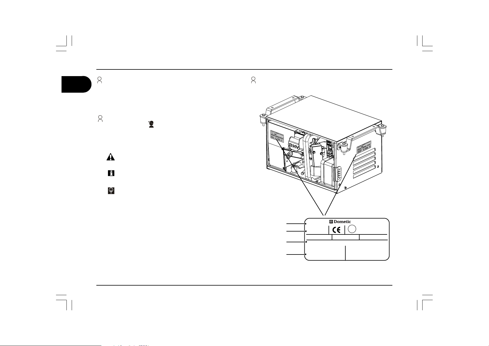
1.2 Data Plate
Manufacturer’s data
Conformity marking
Model/Serial number
Year of manufacture
Technical data
Manufactured by v.Virgilio,3 Forlì-Italy
E13
PRODUCT No. MODEL
958 500 213 TEC 29
Date 2002
Voltage V230
Frequency Hz 50
Power Factor Cos 1
Weight Kg 44
SERIAL
xxxxxxxx
Output max W2900
Output W2600
D.C. 12V A 10
TEC 29 4
user’s manual
Page 5

General information 1
The company Dometic is not responsible for any damage caused by
generator malfunctions.
1.3 Safety
The generator is installed in a closed casing. Therefore, there is no
danger of accidental contacts with moving parts or wires under voltage.
The door is fitted with a key lock which shall be kept out of reach by
children or non-authorised people.
Warning
• Check the generator before using it every time. In this way it is
possible to prevent accidents or damage to the motor.
• To prevent fire hazards and to keep the generator in an efficient
working condition, do not close the same in a case or an enclosed
space such as an alcove but install it in a well-ventilated area.
• Keep children and animals away from the generator when it is
running, as it can heat up and cause burns and injuries, both
directly and through the systems it is supplying.
• Learn how to turn the generator off quickly and how to use the
controls. Never leave the generator in the hands of people who
are not trained to use it.
• The generator must only be used with the generator door closed.
• Keep flammable substances away from the generator such as
for example: petrol, paints, solvents etc.
• Make sure that the hot parts of the generator do not come into
contact with materials that could catch fire.
• Fill the generator with fuel in a well-ventilated area with the
generator turned off. Petrol is highly flammable and can explode.
• Never overfill the fuel tank. There should not be fuel in the tank
filling throat. Check that the cap is tightly closed.
• If you spill any fuel, clean it up thoroughly and wait for the fumes
to evaporate before starting the engine.
• Exhaust gases contain carbon monoxide, an extremely poisonous
gas, which is odourless and colourless. Avoid inhaling exhaust
gases. Do not run the engine of the generator in a closed garage
or room without very good ventilations.
• Do not touch the generator or the connections with wet hands.
• Do not replace fuses or thermal cutouts with others of a higher
amperage.
• Any checks carried out on the electric parts should be done by
authorised personnel with the engine turned off.
• Install the generator in a stable area. Do not incline the generator
by more than 20° with respect to the vertical plane.
• Sudden braking or acceleration, or curves taken abruptly with
the vehicle can cause problems in the pumping system of the
generator and make it stall.
• When storing the generator up for a long period of time, start it at
least once every 30 days and leave it running for at least 15
minutes.
• Leave the generator on for a few minutes without charge after
use before switching it off.
The generator is made to meet the safety regulations indicated in the
declaration of conformity.
1.4 Noise
The generator has been tested for noise emissions at the qualified
independent laboratory DNV Modulo Uno which has issued the EECcertificate based on EC-DIRECTIVE 2000/14.
GUARANTEED AND MEASURED SOUND POWER LEVEL:
TEC29 ..................................................................... LwA 89
---------------------------------------------------------------------------------
SOUND POWER LEVEL measured from 7mt .... dB(A) 54-59
GB
user’s manual TEC 29
5
Page 6
1 General information
GB
1.5 Description of the generator
Warning
The TEC 29 generator has been designed and produced to be used
only on caravans, motor homes and commercial vehicles.
Therefore it has not been designed to be used on other types of vehicles
or on any kind of watercraft. The company Dometic, as it is impossible
to envisage every possible use and type of installation, declines any
responsibility for every type of use and installation which is not explicitly
mentioned.
The generator has been designed to produce alternating current at
230V and 50 Hz, capable of supplying power to various systems.
Therefore it is fitted with an inverter, so that it can supply systems that
are very sensitive to the quality of the energy supplied, such as personal
computers for example.
The generator is installed in a sheet metal steel casing which is insulated
and soundproofed with special soundproofing materials.
1.6 Recommandations for use
To use the generator in the best way it is a good idea to pay attention to
even small overloads, which if prolonged, will cause the protective
thermal cutouts to trip.
When running in it is important not to put the new engine under a load
that exceeds 70 % of the nominal load, at least for the first 50 working
hours; then we recommend a normal use of the generator with a load
equal to roughly 3/4 of the maximum declared continuous load, this in
order to prolong the life of the generator and maximize efficiency.
When the generator is hot we recommend starting by pushing the start
button briefly, while when the generator is cold hold the start button
down for longer.
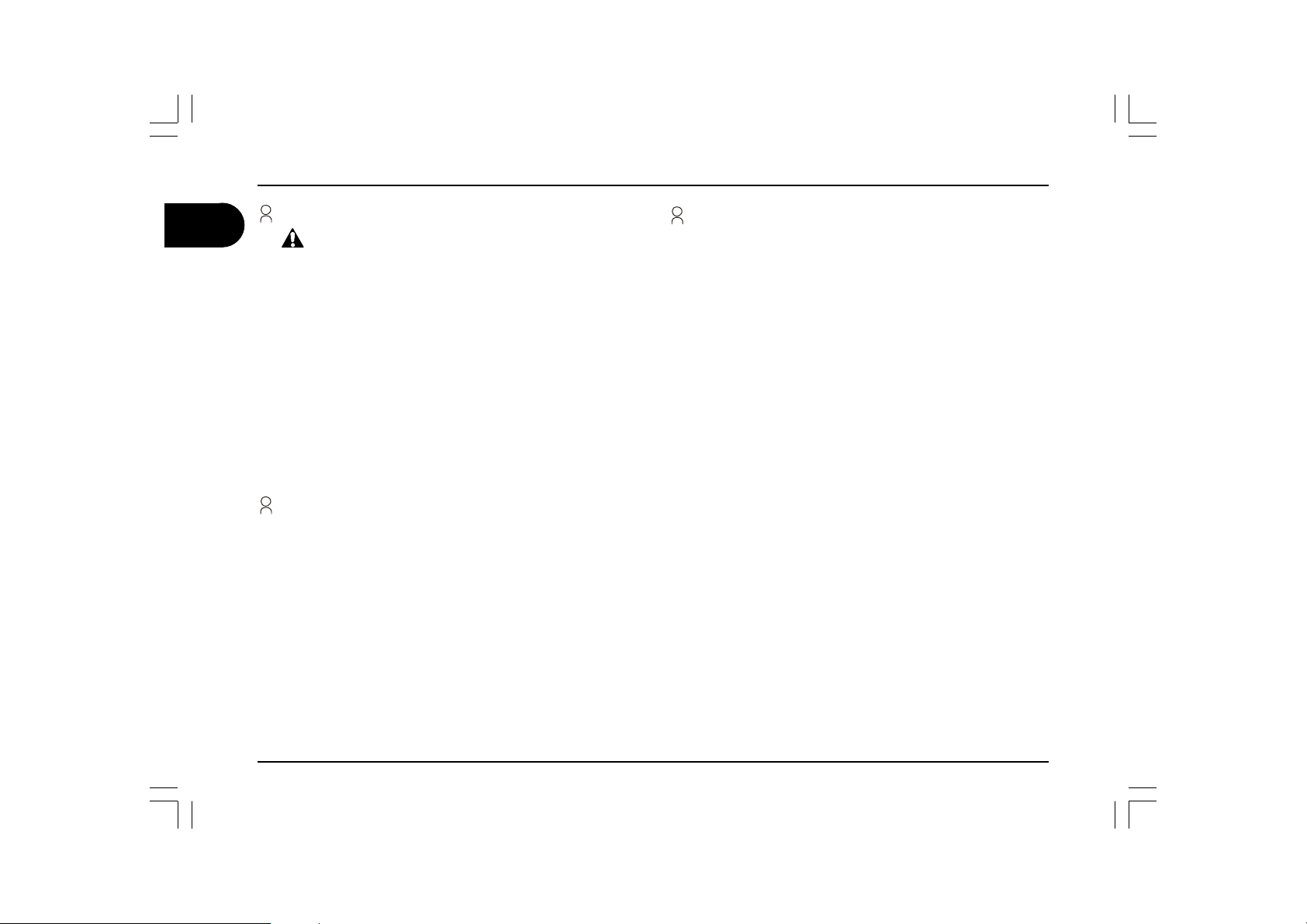
1.7 Operation description
The main elements of the TEC 29 generator are: an engine (a), a
permanent magnet alternator (b), an inverter (c), an internal control
panel (d), a terminal board (e) and an external control panel (f).
When the engine runs it drives the alternator to which it is solidly connected, which in turn generates alternating current that supplies the
inverter. The inverter “converts” the voltage supplied into a higher quality,
perfectly stable voltage of 230 V and 50Hz supply.
The terminals, the socket where the extension of the external control
panel is connected and the safety switch are located on the internal
control panel.
The external control panel is equipped with:
- buttons to start and stop the generator
- a back lit LCD screen showing the main electrical properties, an
indicator shows that the generator is working properly and an hour
counter is also displayed. In the case of problem the alarm messages
are displayed on this screen.
- LED indicators indicate low levels of petrol or oil.
TEC 29 6
user’s manual
Page 7
General information 1
EXTERNAL
CONTROL
PANEL
(F)
ENGINE (A)
ALTERNATOR
UNIT
(B)
STEP MOTOR
MAGNET
INVERTER CONTROL
CARD
(C)
TERMINAL
BOARD (E)
INTERNAL
CONTROL
PANEL
(D)
GB
user’s manual TEC 29
7
Page 8
1 General information
GB
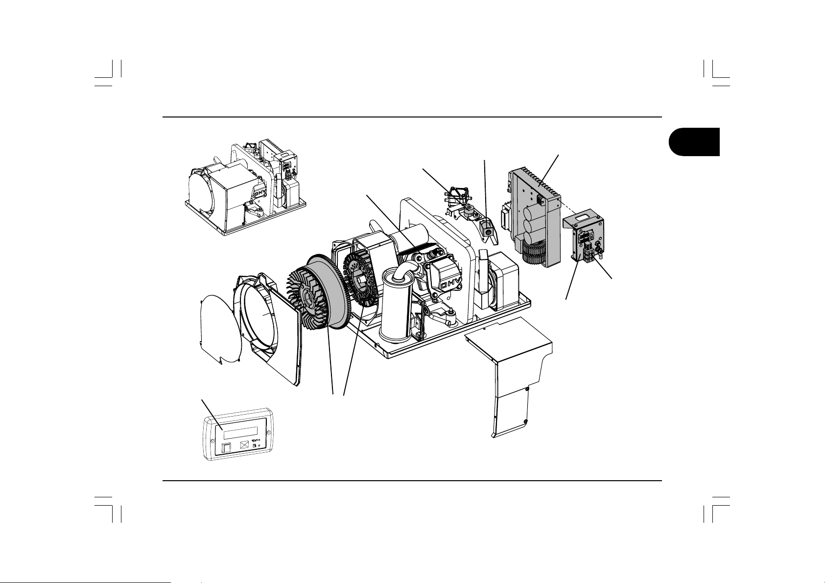
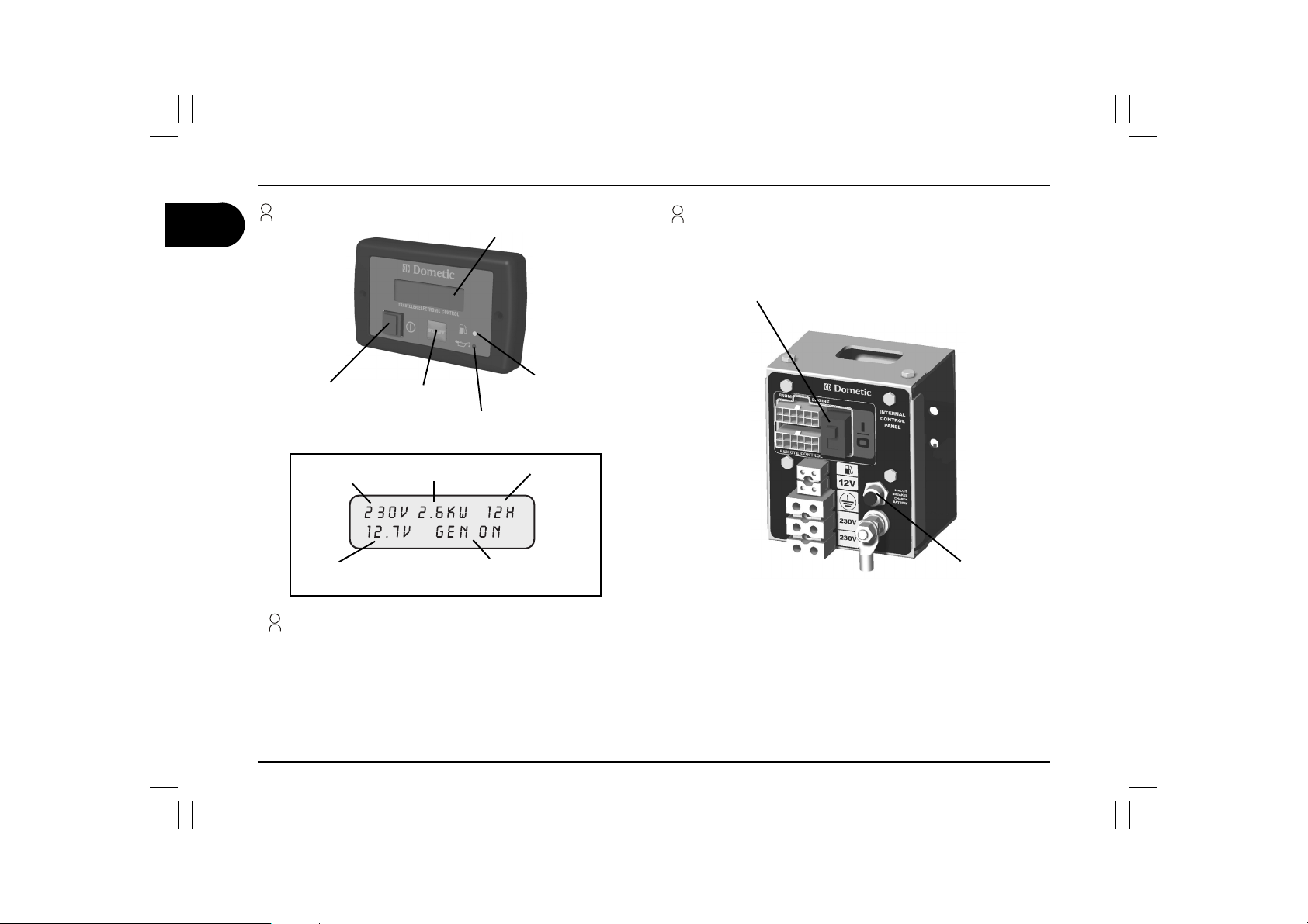
1.8 External control panel
DISPLAY
1.9 Internal control panel
EMERGENCY
STOP SWITCH
MAIN SWITCH
VOLT AG E
DELIVERED
BA TTERY’S DC
VOLT AG E
START
BUTTON
POWER
DELIVERED
OIL
INDICATOR
WORKING HOURS
GENERATOR ST A TUS
PETROL
INDICATOR
Operation description
MAIN SWITCH: turns the panel on/stops the generator
START BUTTON: starts the generator
PETROL INDICATOR: indicates that you are using the fuel reserve
OIL INDICATOR: indicates a low oil level in the engine
EMERGENCY STOP SWITCH: stops the generator immediately in an emergency
CUT OUT SWITCH: continuous current thermal cut out protection
CUT OUT SWITCH
TEC 29 8
user’s manual
Page 9
General information 1
1.10 Technical data
DHTDHT
DHTDHT %%%%% 11111
DHT
THGIEWTHGIEW
THGIEWTHGIEW gkgkgkgkgk 4444444444
THGIEW
NOITPIRCSEDNOITPIRCSED
NOITPIRCSEDNOITPIRCSED ERUSAEMFOTINUERUSAEMFOTINU
NOITPIRCSED
DEILPPUSEGATLOVDEILPPUSEGATLOV
DEILPPUSEGATLOVDEILPPUSEGATLOV VVVVV %01±032%01±032
DEILPPUSEGATLOV
REWOPSUOUNITNOCXAMREWOPSUOUNITNOCXAM
REWOPSUOUNITNOCXAMREWOPSUOUNITNOCXAM WWWWW %5±0062%5±0062
REWOPSUOUNITNOCXAM
YCNEUQERFYCNEUQERF
YCNEUQERFYCNEUQERF zHzHzHzHzH %1±05%1±05
YCNEUQERF
REWOPTNERRUCTCERIDREWOPTNERRUCTCERID
REWOPTNERRUCTCERIDREWOPTNERRUCTCERID A/VA/V
REWOPTNERRUCTCERID
NOITPMUSNOCNOITPMUSNOC
NOITPMUSNOCNOITPMUSNOC h/PH/gh/PH/g
NOITPMUSNOC
A/VA/V 01/2101/21
A/V
ERUSAEMFOTINUERUSAEMFOTINU EULAVEULAV
ERUSAEMFOTINU
h/PH/gh/PH/g 032032
h/PH/g
GB
EULAVEULAV
EULAV
%01±032%01±032
%01±032
%5±0062%5±0062
%5±0062
%1±05%1±05
%1±05
01/2101/21
01/21
032032
032
user’s manual TEC 29
9
Page 10

GB
1 General information
1.11 Table describing the alarm messages appearing on the display
EGASSEMDEYALPSIDEGASSEMDEYALPSID
EGASSEMDEYALPSIDEGASSEMDEYALPSID NOITPIRCSEDNOITPIRCSED
EGASSEMDEYALPSID
YRETTABWOL
EGNAHCLIO
nigne
.lioe
LEUFON
TRELALIO
!TRELAROTARENEG
nirkcehc
!DAOLREVO
TIUCRICTROHS
ERUTAREPMETREVO
ENIGNEREWOPWOL
?NEGTRATSER
LACNEG
eht
.teytnerrucecudorptonseod
TIAWNEG
NONEG
NOITPIRCSEDNOITPIRCSED
NOITPIRCSED
.)V9(rotarenegehttratsotyrassecen
.evreserleufehtgnisuerauoytahtsetacidnI
.knatlioehtnilioeromonsierehT .spotsrotarenegehT .)11egapees(pulliF
deepsrotomehtkcehctonnaceludom011Meht
.gninnursirotarenegehttahtsetacidnI
eulavmuminimehtwolebsiegatlovyrettabehttahtsetacidnI
.smetsysdeilppusehtfodaolrevotuptuonasetacidnI
.smetsysdeilppusehtfotrohstuptuonasetacidnI
.daolrevolamrehtafotneveehtnideyalpsidsiegassemsihT
.retrevniehtotdeilppusegatlovehtfonoitcuderaslangiS .spotsrotarenegehT
.rotarenegehtfopotsynaretfasraeppaegassemsihT .spotsrotarenegehT
.rehtoehtdnatpmettatratsenoneewtebdeyalpsidegasseM .nurtonrotarenegehT
ROTARENEGROTARENEG
ROTARENEGROTARENEG
ROTARENEG
RUOIVAHEB
.trats
ehtforetnuocruohehtemityrevesraeppaegassemsihT
ehtegnahcottes-erplavretniecivresehtsehcaerenihcam
.nur
.nur
ehtnehwecnatsnirofdeyalpsidsiti;egassemmralalareneG
dnaevitcefedsi)rotompets(elttorhtrotterubracehtfog
gnilooc
gnilooc
looc
.”?NEG
setacidnidnapu-tratsrotarenegehttasraeppaegassemsihT
rotarenegehT.pu-tratsynagnidecerpesahpnoitarbilac
tonseodrotarenegehT
otseunitnocrotarenegehT
otseunitnocrotarenegehT
.spotsrotarenegehT
dnaspotsretrevniehT
regnolonsiegatlov
enigneehttub,deilppus
dnaspotsretrevniehT
regnolonsiegatlov
enigneehttub,deilppus
dnaspotsretrevniehT
regnolonsiegatlov
enigneehT.deilppus
TRATSER“sideyalpsid
tubnurrotarenegehT
.deilppustonsiegatlov
.leufeR
tcerrocarofnurotseunitnoc
.straplanretniehtfo
tcerrocarofnurotseunitnoc
.straplanretniehtfo
tcerrocarofnurotseunitnoc
,straplanretniehtfogni
egassemehtdnaspotsneht
.trats
SNOITCASNOITCA
SNOITCASNOITCA
SNOITCA
ehtfoycneiciffeehtkcehC
.rotareneg
.rotarenegeht
sniameht
ehtgnitratserofebyrettab
)12.pees(lioehtegnahC
ehtgnitratsererofeb
ehtgnidlohybrotareneg
.regnolrofnwodnottubtrats
noelbatgnitoohselbuorTeeS
melborpehtfI.81egap
ehtotsserdda,stsisrep
.ertnececivrestseraen
,daoldetcennocehtecudeR
loocotsetunimwefatiaw
ehtpotS.rotarenegehtnwod
T.nottubhctiws
.tinuehttratser
niamehtgnisserpybenigne
tratserneh
detcennocehtllakcehC
setunimwefatiaw,smetsys
.rotarenegehtnwodloocot
gnisserpybenigneehtpotS
.nottubhctiw
,nwodloocrotarenegehtteL
dnasetunimwefatiaw
daoldetcennocehtecudeR
.rotarenegehttratserdna
ffonottubhctiwsniamsserP
ehthsupnehtdnanodna
ottnawuoyfinottubtrats
.rotarenegehttratser
.sdnoceswefatiaW
seogegassemehtlitnutiaW
wenagnitpmettaerofebffo
TEC 29 10
user’s manual
Page 11

General information 1
1.12 Routine maintenance
To perform these checks you should open the door of the generator
taking the following precautions:
The generator must not be running and all of the parts must be cold.
Set the safety switch on the internal control panel to “O” (OFF).
Disconnect the positive pole (+) of the vehicle’s battery
IMPORTANT: Use only genuine spare parts. The generator may
get damaged if other than genuine parts having a different quality
standard are used.
IMPORTANT:
Remember to reconnect the positive pole (+) of the vehicle’s battery
and set the switch back to “I” (ON) once you have finished the checks.
1.13 Checking the oil level
Remove the oil filler and clean the dipstick with a cloth.
Refit by screwing the dipstick.
Remove the dipstick and check that the oil level is between the two
(min. and max.) marks.
Add oil if necessary through the filler. Use only the oil recommended by
the manufacturer!
Refit the plug.
IMPORTANT:
Perform all of the checks making sure the generator is in a horizontal
position.
GB
user’s manual TEC 29
11
Page 12

GB
2 Installation instructions
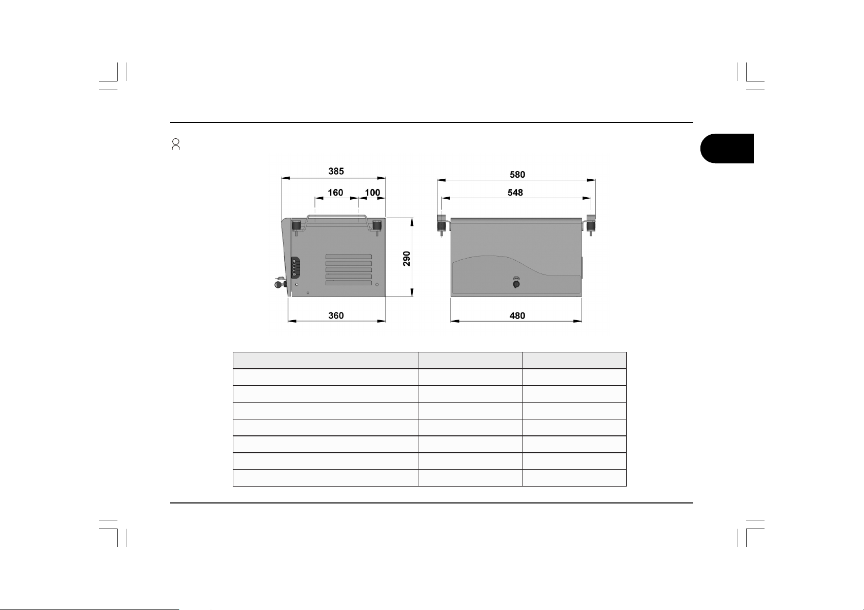
2.1 Instructions for fixing the generator
Make sure there is enough space around the casing of the generator for cooling, leaving at least 20 mm of free space between the casing and the
Warning
surrounding walls or parts. If the air intake of the generator remains behind a wheel of the vehicle, make sure that in the case of rain the wheel will
not spray water onto or into the generator taking preventing measures if necessary (ex. antispray guards).
Omega bracket
Air intake
290
360
580
548
480
99
385
160
Cabinet
10.5
hole
Gasket
Drain
hole
Air intake
Type A
30
295
360
310
23
104
20
35
548
Type B
The brackets supplied make it possible to install the generator both externally (Type A) and internally (Type B).
“Type A ” assembly (external installation) offers the following advantages: less internal space occupied, rapid installation, easy access for the
routine and extraordinary maintenance. For the “Type A” installation you will have to use the “omega brackets” supplied to guarantee that the unit
will be correctly fitted. If you decide to install the generator with the “Type B” installation (internal installation), you will have to prepare a sealed
cabinet inside the vehicle (which can be further sound-proofed), being careful to respect the air space of 20mm between the generator casing and
the surrounding parts, with the exhaust and air intake holes in the floor and door. The air intake must be at least 240 cm2. Furthermore you should
also install a fire-proof rubber gasket of at least 5mm between the floor and the base of the generator (available as accessory Ref. AG128).
TEC 29 12
user’s manual
Page 13

Installation instructions 2
2.2 Instructions for installing the exhaust system
We recommend positioning the elbow of the exhaust pipe in line with the length of the casing (as shown in the figure) so more vibrations can be
absorbed.
Use the exhaust extension (available as accessory Ref. AG125) to extend the position of the muffler. Fix the extension to the floor of the vehicle.
Do not make any sharp bends in the hose which could obstruct the exhaust gas.
WARNING
EXHAUST
ELBOW
TEC 29
EXHAUST
EXTENSION
AG125
EXTENSION
FIXING
MUFFLER
GB
user’s manual TEC 29
13
Page 14

2 Installation instructions
GB
Instructions for installing the exhaust system
TEC 29 14
user’s manual
Page 15

Installation instructions 2
Instructions for installing the exhaust system
GB
user’s manual TEC 29
15
Page 16

GB
2 Installation instructions
2.3 Instructions for installing the tank fuel
The fuel tank should be installed with the tank basis at a maximum depth of 0.3 meters below the lower edge of the generator box. For
safety reasons ensure not to mount the generator box top edge higher than the tank top edge.
TEC 29 16
user’s manual
Page 17

2.4 Instructions for the electrical connection
Make the electrical connections respecting all applicable laws and
regulations.
Warning
You will have to install a relay or commutator in the vehicle’s electrical
system (ex. the accessory AG 102) in order to prevent damaging the
generator when the external mains is connected; in this case we suggest
connecting the generator so that it has priority over the external mains
network.
22222
mmnoitces-ssorCmmnoitces-ssorC
mmnoitces-ssorCmmnoitces-ssorC
mmnoitces-ssorC
V032V032
V032V032
V032
)selbacrewop(
5.25.2
5.25.25.25.2
5.2
Motor cables
connector
Installation instructions 2
22222
mmnoitces-ssorCmmnoitces-ssorC
mmnoitces-ssorCmmnoitces-ssorC
mmnoitces-ssorC
V21V21
V21V21
V21
)regrahcyrettab(
5.25.201010101016161616161
5.2
Emergency stop switch
22222
mmnoitces-ssorCmmnoitces-ssorC
mmnoitces-ssorCmmnoitces-ssorC
mmnoitces-ssorC
m6otpuhtgneLm6otpuhtgneL
m6otpuhtgneLm6otpuhtgneL
m6otpuhtgneL
)noitcennocyrettab(
22222
mmnoitces-ssorCmmnoitces-ssorC
mmnoitces-ssorCmmnoitces-ssorC
mmnoitces-ssorC
m6>htgneLm6>htgneL
m6>htgneLm6>htgneL
m6>htgneL
)noitcennocyrettab(
GB
Electric wiring must be effected in conformity with the existing laws
and regulations in force in the user’s country.
For correct installation performed by the final user, use preventive
External control
panel socket
technical assistance by your seller or by a skilled technician.
For the 230 V use a cable of a standard cross-section as shown in
the table; insert it in the casing through the cable guide and connect
it to the terminals. Connect the earth wire.
Electrical connection of the battery charger
17
Socket for
tank float
wire
12 V plug
for battery
charger
Earth wire
230 V
plug
Cut out switch
(+) plus
pole
Use a cable with a suitable cross-section as shown in the table,
connecting it to the terminal and to the positive pole of the battery you
want to charge. (See picture on page 18)
user’s manual TEC 29
Page 18

GB
2 Installation instructions
Battery connection
NB:Starting electrical input must be 12V DC.
Starting battery should be efficient and with minimum capacity of
60 Ah.
To start the generator, connect it to the positive pole of the vehicle’s
battery with a sheathed cable of a suitable cross-section as shown
in the table. The ground cable must have the same cross-section
and be connected or as shown in the figure to the side or from the
inserts to the frame of the vehicle. Make sure that the contact is
good. If necessary remove paint or rust from the surface of the frame
and protect the connection with grease.
To protect the DC wiring use a 100Amp fuse closed to the plus
pole of the battery.
External control panel connection
Choose the desired position inside the vehicle, use the extension
lead (supplied) to connect the external control panel to the internal
control panel of the generator.
Inserts
TEC 29 18
user’s manual
Page 19

3.1 Faults, causes and solutions
The emergency stop sw itch is not to on
The starter is not powered up
The electrical cables are broken
The generator earth wire is broken
No fuel
The choke is not available
The throttle valvle is blocked
No current to the sp ark plug
No petrol to the carburettor
The air filter is dirty
The Air intakes are obstructed
The inverter is damaged
Load over 2.6 kW
Low battery charge
The starter shaf t is dirty
The stepper mo tor is down or disconnected
Too much oil in the engine
Operations to be carried out by the user
Operations to be carried out by qualified
technicians
CAUSE
By operating the main switch, the panel
does not switch on
By pushing the start button,
the generator does not start (the starting
motor does not run)
The starting motor runs but the generator
does not start
The generator tends to stall
The generator runs but it does not produce
current
The generator starts, then stops and
display “generator allert” message
Troubleshooting, maintenance, recycling 3
GB
SOLUTION
The produced current oscillates
user’s manual TEC 29
19
Page 20

GB
r
3 Troubleshooting, maintenance, recycling
3.2 Check list and time intervals
ecnanetniamenituoRecnanetniamenituoR
ecnanetniamenituoRecnanetniamenituoR
ecnanetniamenituoR
tsrifsruccohcihwtahtotgnidroccasruoh
lioenignE
retlifriAnaelC
gulpkrapSnaelc-kcehC
tnemtsujdaevlaVtsujda-kcehC
natleuFegnahC-naelC
retlifdnak
stniopgnixiffoorp-noitarbiV
enilesohleuF
htretfaroslavretnideludehcsehttatuodeirraceboT
gninnurnevige
kcehC
egnahC
kcehC
fiecalper(kcehC
)yrassecen
retfA
yreve
esu
retfA
tsrifeht
htnom
02ro
sruoh
3yrevE
shtnom
05ro
sruoh
6yrevE
shtnom
001ro
sruoh
sraey2yrevE
yrevE
oraey
003
sruoh
TEC 29 20
user’s manual
Page 21

3.3 Extraordinary maintenance
For some maintenance operations there is the possibility of pulling the
generator out by sliding the entire bottom of the generator on the guides
fixed to the sidewalls of the casing. To free the bottom unscrew the
fixing screws.
Changing the oil
Troubleshooting, maintenance, recycling 3
GB
Fixing
screw
• Hot oil can burn your skin!
• Check the oil level with the engine turned off.
Old oil moust not be disposed of in the environment, but left to a
station specialised in the disposal and/or recycling of the same,
respecting the laws in the country where the operations are carried
out.
Use API SG or SF oil for 4-stroke engines (this indication is on the oil
can).
SAE 10W-30 oil is recommended for general use at all temperatures. If
you use monograde oil, choose the appropriate viscosity on the basis
of the average temperature of the place where the generator is installed.
To drain the old oil easier you should run the generator for roughly 3/5
minutes, in this way the oil is more fluid and will drain better through
the drain tube when you remove the drain plug. Refill the generator
with oil of the recommended type, through the oil filler.
The quantity of oil is:
Warning
Important
Fixing
screw
0.6 Litres
user’s manual TEC 29
21
Page 22

GB
3 Troubleshooting, maintenance, recycling
Air filter maintenance
Do not use diesel or solvents with a low evaporation point to clean the
air filter element as it could catch fire or explode.
If the air filter is dirty this reduces the flow of air to the carburettor.
Therefore, to prevent carburettor malfunctions we recommend checking
the state of the filter periodically, and more often if you are using the
TEC 29 in particularly dusty areas.
Never use the engine without the air filter. The engine would wear
quickly.
Carefully check the integrity of both the elements and replace them if
they are damaged.
Sponge element: wash the element in a solution containing neutral
detergent, rinse thoroughly. Let the element dry completely and
immerge it in clean engine oil before wringing the excess oil out.
Paper element: lightly tap the element on a hard surface to remove the
excess dirt, or blow the filter clean from the inside out with compressed
air. Never brush the dirt off: in fact brushing pushes the dirt into the
fibres of the paper element. Replace the paper element if it is very
dirty.
Warning
Important
TEC 29 22
user’s manual
Page 23

Spark plug maintenance
Troubleshooting, maintenance, recycling 3
GB
The spark plug must be properly tightened. A loose spark plug can
Warning
become very hot and damage the engine.
Important
When fitting a new spark plug, tighten it by half a turn after it has
started compressing the washer. If you are fitting a used spark plug,
tighten it by between 1/8 to 1/4 of a turn after the same has started to
compress the washer.
Never use a spark plug with a different heat rating:
1. Remove the cap of the spark plug and remove it using a wrench.
2. Check the spark plug by eye. Replace the spark plug if it is worn
or the insulation is broken or chipped. If the spark plug is just
dirty, clean it with a wire brush and if is still in a good condition,
use it again.
3. Measure the distance between the electrodes with a feeler gauge.
This distance must be 0.7-0.8 mm. If necessary adjust this
distance by bending the electrode.
4. Check that the washer of the spark plug is in a good condition, if
this is the case screw the spark plug in by hand, to avoid stripping
the thread.
5. Once you have screwed the spark plug in by hand, tighten it with
a plug wrench to compress the washer.
0.7 - 0.8 mm
user’s manual TEC 29
23
Page 24

GB
2
TEC 29 WIRING DIAGRAM
BLACK
BLACK
BLUE
PINK
VIOLET
YELLOW
BROWN
BLACK
RED
BLUE
GREEN
8
321
YELLOW
GREY6RED
BLACK
ORANGE
5679812 11 10
WHITE
GREY
4
4
BROWN
RED
WHITE
12345679810
VIOLET
PINK
WHITE
1234
GREY
6
42
5
31
7
11
9
12
8
10
2
23
VIOLET
GREY
WHITE
BLUE
GREEN
2145876 3
YELLOW
BROWN
BLACK
11 10 912
RED
PINK
7
17
16
0/1
18
B
15
12
230
230
19
20
DESCRIPTION
THREE- PH ASE COI L
1
AUXILIARY COIL
2
AUXILIARY COIL
3
INVERTER MODULE
4
9-PIN CONNECTOR
5
12V REGULATOR
6
STEP MO T OR
7
4-PIN CONNECTOR
8
START RELAY
9
STARTING MO TO R
10
CHOKE MAGNET
11
OIL ALERT
12
MOTOR COIL
13
INT E RNAL CONTROL PANEL
14
THERMAL SWITCH
15
INTERFACE MODULE
16
0/1 EMERGENCY STOP SWITCH
17
10-PIN MINI-F IT CONNECTOR
18
BATTERY PLUS POLE BUSH
19
BATTERY
20
2-PIN MINI-FIT CONNECTOR
21
VEHICLE CONTROL PANEL
22
12-PIN MINI-F IT CONNECTOR
23
AUXILIARY COIL
24
CYL INDRICAL CONNECT OR
25
1
CYAN
CYAN
CYAN
BROWN
BROWN
132
465879
5
21
2
3
24
BLACK WHITE
BLACK
WHITE
WHITE
1
WHITE
2
25
1 2
BLACK
GREY
12
13
11
9
RED
10
M
14
TEC 29 24
user’s manual
Page 25

WIRING DIAGRAM - 2 TEC29 IN PARALLEL MODE
1
For parallel connection of 2
TEC29 follow the diagram in the
picture .
MAINS
BA TTER Y
2
1
LOAD
R1
R2
R3
R4 4
GB
AG 113
A2
3
4 mm
4 mm
4 mm
A1
2
2
2
2.5 mm
2.5 mm
(Accessory sold upon request)
2
230
2
2.5 mm
TEC 29
230
12
#1
230
TEC 29
230
2
12
#2
Compulsorily: use change-over switch AG113 to protect the units against accidental connection to the main electric line
WARNING!
All generators connected to the wiring system must be on off position before executing any maintenance operation!
user’s manual TEC 29
25
Page 26

21
57
12
11
41
40
39
38
8
47
50
49
35
48
46
20
19
56
55
45
44
43
42
37
36
34
33
32
31
30
29
28
27
26
25
24
23
22
1
1
18
17
16
15
13
10
9
6
1
7
5
3
2
4
1
51
54
53
52
58
59
14
60
61
62
63
TEC 29 SPARE PARTS TABLE
GB
25
46
10
37
48
52
62
AG 102
21
5
26
54
12
3
27
53
11
57
15
4
19
2
9
60
14
49
13
28
35
1
47
31
24
61
50
58
59
17
32
16
29
30
1
18
20
7
23
56
55
33
6
1
40
22
42
34
43
1
36
63
8
39
38
41
44
45
51
TEC 29 26
user’s manual
Page 27

TEC 29 SPARE PARTS TABLE
L
FRONT PLATE - INTERNAL CONTROL PANE
N. Description
1 GX 160 MOTOR
2STATOR
3 ROTOR
4 ALTERNATOR COVE R
5FAN LEAD NUT
6INVERTER
7ENGINE WALL
8 STEP MOTOR
9 EXHAUST PIPE
10 PE TR OL PUMP
11 CONTROL PANEL BOX
12 CONTROL PANEL CARD
13 CHOKE MAGNET
14 CU RVE D EXHAUST PIPE
15 ALTE RNATO R CABLE GUIDE
16 12V REGULATOR
17 ENGINE START RELAY
18 AIR INTAKE MANIFOL D
19 STARTING MOTOR
20 ENGINE WALL SEAL
21 CONTROL PANEL
22 INTERNAL CONTROL PANEL CARD
23 CASING BASE
24 ENGINE SUPPORTING BRACKET
25 GENERATOR CASING
26 FA N COVER PLATE
27 SILENCER PLATE
28 METAL STOP - REAR SEAL
29 METAL STOP - TOP SEAL
30 METAL STOP - DOOR SEAL
31 METAL STOP - BOTTOM SEAL
32 STEP MOTOR FIXING PLATE
33 SUPPORT.PLATE - INT. CONTROL PANE
34
35 SPARK PLUG METAL FLAP
36 GEN. / INVERTER CASING DOOR
37 SHAPED CABLE GUIDE
38 RUBBER CABLE GUIDE
39 METAL SPACER
40 STEP MOTOR SUPPORTING PLATE
41 GAS LEVER
42 15A THERMAL CUTOUT
43 TERMINAL
44 BUSH D7x16xH7 /D10xH4
45 BUSH D10.5 X 16 H3
46 CASING VIBRATION-PR OO F BRACKET
47 OIL DIPSTICK
48 OMEGA-BRACKETS
49 SILENCER
50 SILENCER FIXING BRACKET
51 TEC29 WIRING
52 SOUND-PROOFING KIT
53 INSULATION KIT
54 CONTROL PANEL EXTENSION
55 LOCK
56 DOOR STICKER
57 CONTROL PANEL STICKER
58 HOSE CLAMP
59 FERRITE
60 NUT
61 WASHER
62 AG102
63 EXHAIST EXTENSION
GB
user’s manual TEC 29
27
Page 28

AG 102
AG 111
EXTERNAL INLET SOCKET
SPINA ESTERNA
1
GENERATOR
12
230
230
A
B
USER CONTROL UNIT
red - rosso
black - nero
blue
7
9
63
4
1
CENTRALINA UTILIZZI
GB
EXTERNAL INLET SOCKET
SPINA ESTERNA
CHANGEOVER SWITCH AG102 - WIRING DIAGRAM
USER CONTROL UNIT
CENTRALINA UTILIZZI
GENERATOR
230
230
red - rosso
black - nero
blue
12
AG 111
AG 102
TEC 29 28
user’s manual
 Loading...