

Page 1

RM 8400 RM 8401 RM 8405 RM 8500 RM 8501 RM 8505 RM 8550 RM 8551 RM 8555
RMS 8400 RMS 8401 RMS 8405 RMS 8460 RMS 8461 RMS 8465 RMS 8500 RMS 8501
RMS 8505 RMS 8550 RMS 8551 RMS 8555 RML 8550 RML 8551 RML 8555 RMSL 8500
RMSL 8501 RMSL 8505
MBA 05/2012
N 1-1
Einbauanleitung
Absorber-Kühlschrank für Freizeitfahrzeuge
DE
Deutsch
Page 2
©
Dometic GmbH - 2011 - Änderungen vorbehalten
0.0 Auspacken und Transport . . . . . . . . . . . . . . . . . . . . . . . . . . . . . . . . 3
1.0 Allgemeines . . . . . . . . . . . . . . . . . . . . . . . . . . . . . . . . . . . . . . . . . . . 4
1.1 Einleitung . . . . . . . . . . . . . . . . . . . . . . . . . . . . . . . . . . . . . . . . . . . . . . . . . . . . . . . . . . . . . . . . . . 4
1.2 Hinweise zu dieser Bedienungsanleitung . . . . . . . . . . . . . . . . . . . . . . . . . . . . . . . . . . . . . . . . . 4
1.3 Urheberschutz . . . . . . . . . . . . . . . . . . . . . . . . . . . . . . . . . . . . . . . . . . . . . . . . . . . . . . . . . . . . . . 4
1.4 Erklärung der verwendeten Symbole . . . . . . . . . . . . . . . . . . . . . . . . . . . . . . . . . . . . . . . . . . . . . 4
1.5 Gewährleistung . . . . . . . . . . . . . . . . . . . . . . . . . . . . . . . . . . . . . . . . . . . . . . . . . . . . . . . . . . . . . 5
1.6 Haftungsbeschränkung . . . . . . . . . . . . . . . . . . . . . . . . . . . . . . . . . . . . . . . . . . . . . . . . . . . . . . . 5
1.7 Konformitätserklärung . . . . . . . . . . . . . . . . . . . . . . . . . . . . . . . . . . . . . . . . . . . . . . . . . . . . . . . . 5
2.0 Sicherheitshinweise . . . . . . . . . . . . . . . . . . . . . . . . . . . . . . . . . . . . . 6
2.1 Bestimmungsgemäße Verwendung . . . . . . . . . . . . . . . . . . . . . . . . . . . . . . . . . . . . . . . . . . . . . . 6
2.2 Verantwortung des Nutzers . . . . . . . . . . . . . . . . . . . . . . . . . . . . . . . . . . . . . . . . . . . . . . . . . . . . 6
2.3 Arbeiten und Überprüfungen am Kühlschrank . . . . . . . . . . . . . . . . . . . . . . . . . . . . . . . . . . . . . 6
2.4 Betreiben des Kühlschrankes mit Gas . . . . . . . . . . . . . . . . . . . . . . . . . . . . . . . . . . . . . . . . . . . . 6
3.0 Modellbeschreibung . . . . . . . . . . . . . . . . . . . . . . . . . . . . . . . . . . . . 7
3.1 Modellbezeichnung . . . . . . . . . . . . . . . . . . . . . . . . . . . . . . . . . . . . . . . . . . . . . . . . . . . . . . . . . . 7
3.2 Typenschild des Kühlschranks . . . . . . . . . . . . . . . . . . . . . . . . . . . . . . . . . . . . . . . . . . . . . . . . . . 7
3.3 Technische Daten . . . . . . . . . . . . . . . . . . . . . . . . . . . . . . . . . . . . . . . . . . . . . . . . . . . . . . . . . . . . 7
4.0 Einbauanleitung . . . . . . . . . . . . . . . . . . . . . . . . . . . . . . . . . . . . . . . . 10
4.1 Einbau . . . . . . . . . . . . . . . . . . . . . . . . . . . . . . . . . . . . . . . . . . . . . . . . . . . . . . . . . . . . . . . . . . . . 10
4.1.1 Seitlicher Einbau . . . . . . . . . . . . . . . . . . . . . . . . . . . . . . . . . . . . . . . . . . . . . . . . . . . . . . . . . . . . . . . . . . . . . 10
4.1.2 Seitlicher Einbau mit Boden-Dach-Ventilation . . . . . . . . . . . . . . . . . . . . . . . . . . . . . . . . . . . . . . . . . . . . . . 11
4.1.3 Heckeinbau . . . . . . . . . . . . . . . . . . . . . . . . . . . . . . . . . . . . . . . . . . . . . . . . . . . . . . . . . . . . . . . . . . . . . . . . . 11
4.1.4 Zugdichter Einbau . . . . . . . . . . . . . . . . . . . . . . . . . . . . . . . . . . . . . . . . . . . . . . . . . . . . . . . . . . . . . . . . . . . 12
4.2 Be- und Entlüftung des Kühlschranks . . . . . . . . . . . . . . . . . . . . . . . . . . . . . . . . . . . . . . . . . . . . 13
4.3 Einbau der Lüftungssysteme . . . . . . . . . . . . . . . . . . . . . . . . . . . . . . . . . . . . . . . . . . . . . . . . . . . 14
4.4 Abgasführung und Anbringung des Abgaskamins . . . . . . . . . . . . . . . . . . . . . . . . . . . . . . . . . . 15
4.5 Einbaunische . . . . . . . . . . . . . . . . . . . . . . . . . . . . . . . . . . . . . . . . . . . . . . . . . . . . . . . . . . . . . . . 16
4.5.1 Aufstellung in der Nische . . . . . . . . . . . . . . . . . . . . . . . . . . . . . . . . . . . . . . . . . . . . . . . . . . . . . . . . . . . . . . 16
4.6 Kühlschrankbefestigung . . . . . . . . . . . . . . . . . . . . . . . . . . . . . . . . . . . . . . . . . . . . . . . . . . . . . . . 17
4.7 Einsetzen der Dekorplatte . . . . . . . . . . . . . . . . . . . . . . . . . . . . . . . . . . . . . . . . . . . . . . . . . . . . . 17
4.8 Gasinstallation . . . . . . . . . . . . . . . . . . . . . . . . . . . . . . . . . . . . . . . . . . . . . . . . . . . . . . . . . . . . . . 19
4.9 Elektrische Installation . . . . . . . . . . . . . . . . . . . . . . . . . . . . . . . . . . . . . . . . . . . . . . . . . . . . . . . . 21
4.9.1 Netzanschluss . . . . . . . . . . . . . . . . . . . . . . . . . . . . . . . . . . . . . . . . . . . . . . . . . . . . . . . . . . . . . . . . . . . . . . . 21
4.9.2 Batterieanschluss . . . . . . . . . . . . . . . . . . . . . . . . . . . . . . . . . . . . . . . . . . . . . . . . . . . . . . . . . . . . . . . . . . . . 21
4.9.3 Kabelanschlüsse . . . . . . . . . . . . . . . . . . . . . . . . . . . . . . . . . . . . . . . . . . . . . . . . . . . . . . . . . . . . . . . . . . . . . 22
4.9.4 D+ und Solaranschluss . . . . . . . . . . . . . . . . . . . . . . . . . . . . . . . . . . . . . . . . . . . . . . . . . . . . . . . . . . . . . . . . 24
4.9.5 Schaltschemata . . . . . . . . . . . . . . . . . . . . . . . . . . . . . . . . . . . . . . . . . . . . . . . . . . . . . . . . . . . . . . . . . . . . . 25
2
Inhaltsverzeichnis
Dometic GmbH
In der Steinwiese 16
D-57074 Siegen
www.dometic.com
Page 3
3
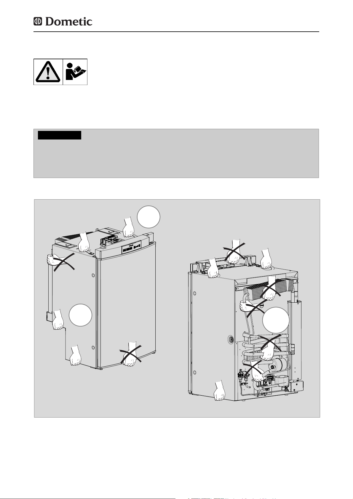
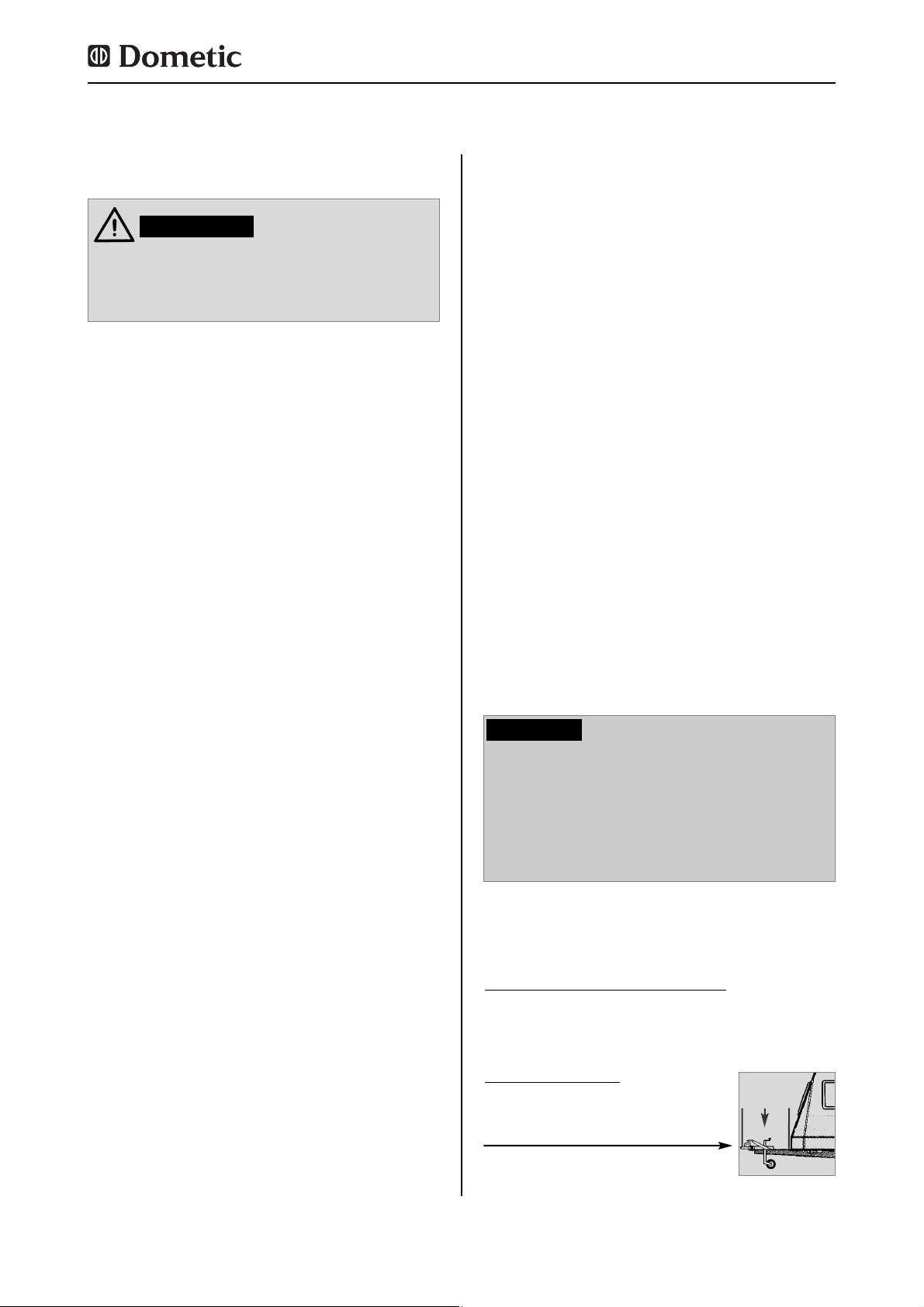
Anheben / Tragen des Kühlschranks
0.0 Auspacken und Transport
Nutzen Sie niemals zum Tragen oder Anheben des Kühlschranks andere Teile am Kühlschrank als die in der Abbildung gezeigten ( vor allem nicht das Aggregat, Gasleitungen
und Bedienblende) !
Sie vermeiden Beschädigungen am Kühlschrank !
VORSICHT!
NEIN
JA
JA
Page 4
4
1.0 Allgemeines
Beim Einbau des Gerätes müssen die technischen und administrativen Vorschriften des
Landes, in dem das Fahrzeug zum ersten Mal
zugelassen wird, beachtet werden.
Ansonsten sind die Einbauvorschriften des
Herstellers zu beachten. In Europa z.B. müssen Gasgeräte, Leitungsverlegung, Gasflaschenaufstellung sowie Abnahme und
Dichtheitsprüfung der Europäischen Norm EN
1949 für Flüssiggasanlagen in Fahrzeugen
entsprechen.
1.1 Einleitung
Bevor Sie den Kühlschrank einbauen, lesen
Sie diese Installationsanleitung bitte sorgfältig durch.
Diese Anleitung gibt Ihnen die nötigen
Hinweise für den richtigen Einbau Ihres
Kühlschrankes. Beachten Sie besonders die
Sicherheitshinweise. Die Einhaltung der
Hinweise und Handlungsanweisungen ist
wichtig und schützt Sie und den Kühlschrank
vor Schäden. Das Gelesene muss verstanden
worden sein, bevor Sie eine Maßnahme durchführen.
Bewahren Sie diese Installationsanleitung
sorgfältig auf, sodass sie jederzeit verwendet werden kann.
1.2 Hinweise zu dieser
Installationsanleitung
Allgemeines
Die Angaben, Texte und Abbildungen in dieser
Anleitung sind urheberrechtlich geschützt und
unterliegen den gewerblichen Schutzrechten.
Kein Teil dieser Anleitung darf ohne die schriftliche Genehmigung der Dometic GmbH,
Siegen, reproduziert, kopiert oder sonstwie
verwendet werden.
1.3 Urheberschutz
1.4 Erklärung der verwendeten
Symbole
Warnhinweise sind durch Symbole gekennzeichnet. Ein ergänzender Text erläutert Ihnen
den Grad der Gefährdung.
Beachten Sie diese Warnhinweise sehr
genau. Damit schützen Sie sich, andere
Personen und das Gerät vor Schäden.
Warnhinweise
GEFAHR kennzeichnet eine unmittelbare
Gefahrensituation, die zum Tod oder einer ernsten Verletzung führen kann, wenn die angegebenen Anweisungen nicht befolgt werden.
GEFAHR!
WARNUNG kennzeichnet eine mögliche
Gefahrensituation, die zum Tod oder einer ernsten Verletzung führen kann, wenn die angegebenen Anweisungen nicht befolgt werden.
WARNUNG!
VORSICHT kennzeichnet eine mögliche
Gefahrensituation, die zu leichten oder mittleren Verletzungen führen kann, wenn die angegebenen Anweisungen nicht befolgt werden.
VORSICHT!
VORSICHT ohne Sicherheitssymbol kennzeich-
net eine mögliche Gefahrensituation, die zu
Beschädigungen des Gerätes führen kann,
wenn die angegebenen Anweisungen nicht
befolgt werden.
VORSICHT!
Page 5
5
Allgemeines
Gewährleistungsabwicklungen erfolgen nach
der europäischen Richtlinie 44/1999/EC und
den landesüblichen Bedingungen. Im
Gewährleistungs- oder Servicefall wenden Sie
sich bitte an unseren Kundendienst.
Störungen, die auf fehlerhafte Bedienung
zurückzuführen sind, unterliegen nicht der
Gewährleistung. Jede Veränderung am Gerät
oder die Verwendung von Ersatzteilen, die
keine Original - Dometic - Ersatzteile sind,
sowie das Nichteinhalten der Einbau- und
Bedienungsanleitung führt zum Erlöschen der
Gewährleistung und zum Ausschluss von
Haftungsansprüchen.
1.5 Gewährleistung
Alle Angaben und Hinweise in dieser Einbauanleitung wurden unter Berücksichtigung geltender Normen und Vorschriften sowie dem
Stand der Technik erstellt. Dometic behält
sich vor, jederzeit Änderungen am Produkt
vorzunehmen, die im Interesse der
Verbesserung des Produktes und der
Sicherheit angebracht sind.
Dometic übernimmt keine Haftung für
Schäden bei :
Nichtbeachtung dieser Anleitung
nicht bestimmungsgemäßer Verwendung
Verwendung von nicht originalen
Ersatzteilen
Veränderungen und Eingriffen am Gerät
Einwirkung von Umgebungseinflüssen, wie
- Temperaturänderungen
- Luftfeuchtigkeit
1.6 Haftungsbeschränkung
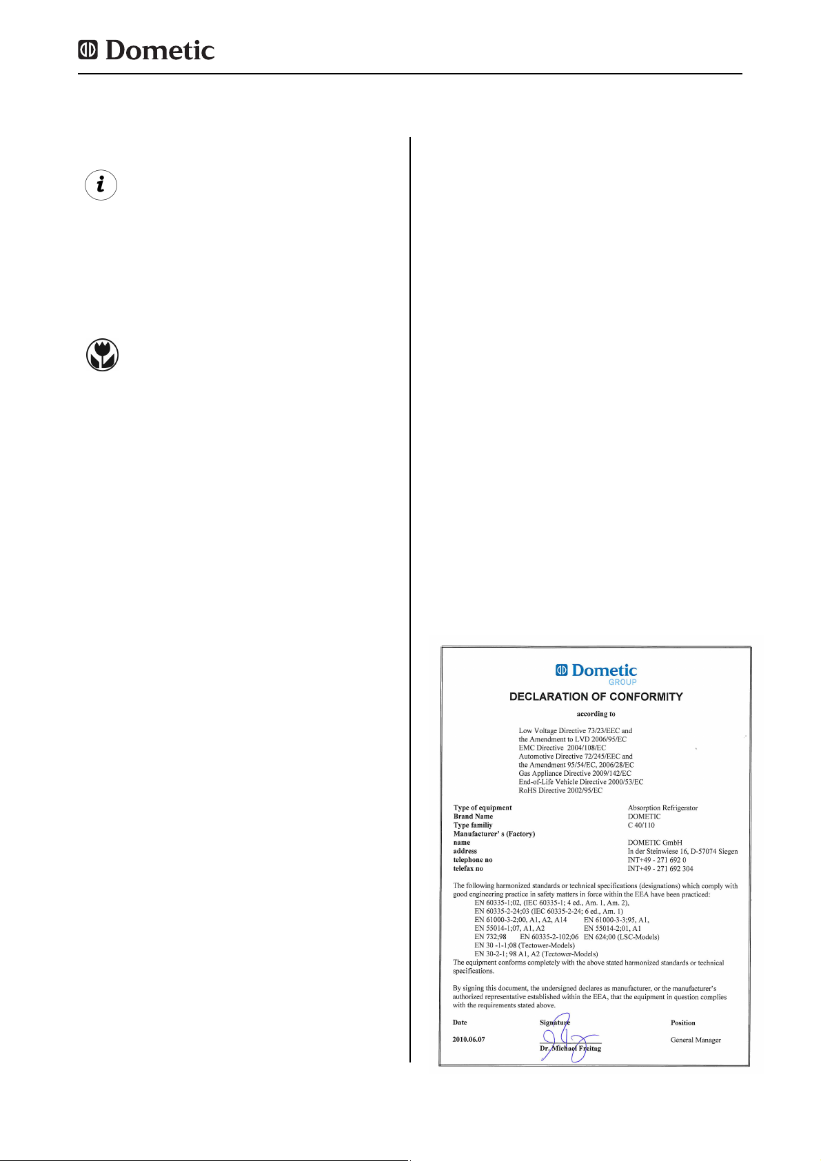
1.7 Konformitätserklärung
Information
INFORMATION gibt Ihnen ergänzende und
nützliche Hinweise zum Umgang mit Ihrem
Kühlschrank.
Umwelthinweis
UMWELTHINWEIS gibt Ihnen nützliche
Hinweise zur Energieeinsparung und
Entsorgung des Gerätes.
Page 6
6
Sicherheitshinweise
2.0 Sicherheitshinweise
Dieser Kühlschrank ist für den Einbau in
Freizeitfahrzeuge wie Wohnwagen oder
Reisemobile vorgesehen. Das Gerät ist für
diese Anwendung in Konformität mit der EUGasgeräterichtlinie baumustergeprüft.
Benutzen Sie den Kühlschrank ausschließlich
zum Kühlen und Lagern von Lebensmitteln.
2.1 Bestimmungsgemäße
Verwendung
2.3 Arbeiten und Überprüfungen
am Kühlschrank
Arbeiten an den Gas-, Abgas- und
Elektroeinrichtungen dürfen nur von autorisierten Fachkräften ausgeführt werden.
Durch nicht fachgerechte Maßnahmen
können erhebliche Sach- und/oder
Personenschäden entstehen.
WARNUNG!
Überprüfen Sie niemals gasführende Teile
und Leitungen mit einer offenen Flamme auf Undichtigkeit !
Es besteht Brand- oder Explosionsgefahr.
GEFAHR!
Öffnen Sie niemals das Absorberkühlaggregat ! Es steht unter hohem Druck.
Es besteht Verletzungsgefahr!
WARNUNG!
Personen, die den Kühlschrank bedienen,
müssen mit dem sicheren Umgang vertraut
sein und die Hinweise der Bedienungsanleitung kennen.
2.2 Verantwortung des Nutzers
Der Betriebsdruck muss unbedingt der
Angabe auf dem Typenschild des
Kühlschranks entsprechen. Vergleichen Sie
die Angabe des Betriebsdruckes auf dem
Typenschild mit den Daten des
Druckminderers an der Flüssiggasflasche.
2.4 Betreiben des Kühlschranks
mit Gas
Der Kühlschrank darf nicht dem Regen
ausgesetzt werden.
VORSICHT!
Page 7
7
Modellbeschreibung
Alle Dometic Kühlschränke sind für den
Anschlussdruck 30 mbar ausgerüstet.
Verwenden Sie bei einem Anschluss an eine
50 mbar-Anlage den Truma Vordruckregler
VDR 50/30.
3.0 Modellbeschreibung
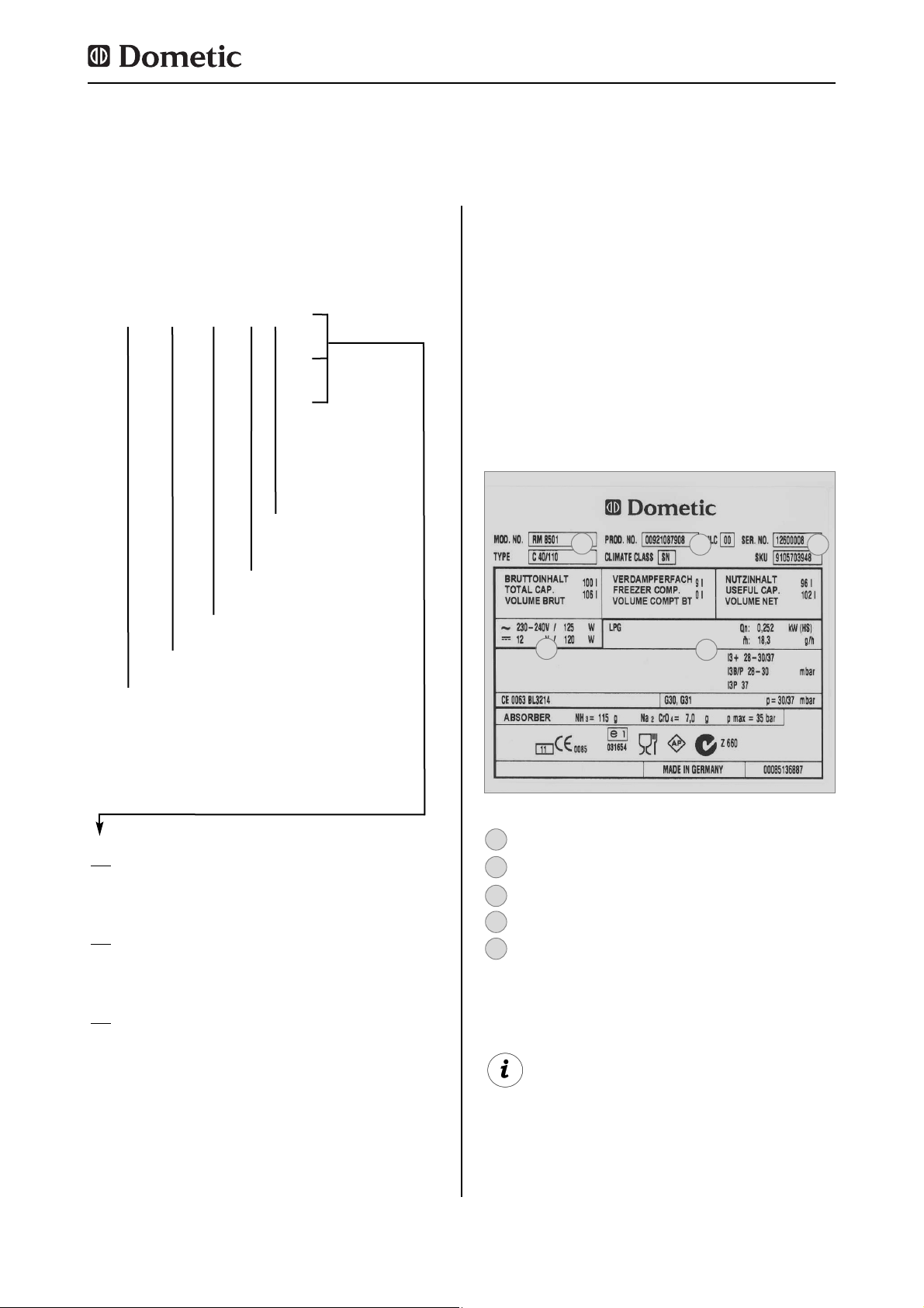
3.1 Modellbezeichnung
Im Inneren des Kühlschranks finden Sie das
Typenschild des Kühlschranks. Es enthält alle
wichtigen Angaben zum Kühlschrank. Dort
können Sie die Modellbezeichnung, die
Produktnummer und Seriennummer ablesen.
Diese Angaben benötigen Sie bei allen
Kontakten mit dem Kundendienst oder der
Ersatzteilbestellung.
3.2 Typenschild des Kühlschranks
Modellnummer
Produktnummer
Seriennummer
Elektrische Anschlusswerte
Gasdruck
2
1
3
4
5
RM
8 4 0 0
1
5
(S)
(L)
Refrigerator Mobile /
Mobiler Absorberkühlschrank
0
manuelle Energiewahl + manuelle Zündung
(Batteriezünder)
1
manuelle Energiewahl, automatische
Zündung (MES)
5
automatische und manuelle Energiewahl,
automat. Zündung (AES)
Modellreihe
4 = Breite 486mm
5 = Breite 523mm
Gerätetiefe :
0 = Standard
5 = + 55mm
6 = + 65mm
Stufenschrank
„Large“
Beispiel :
Abb. 1
Beispiel
2
1
3
4
5
Page 8
8
3.3 Technische Daten
Modellbeschreibung
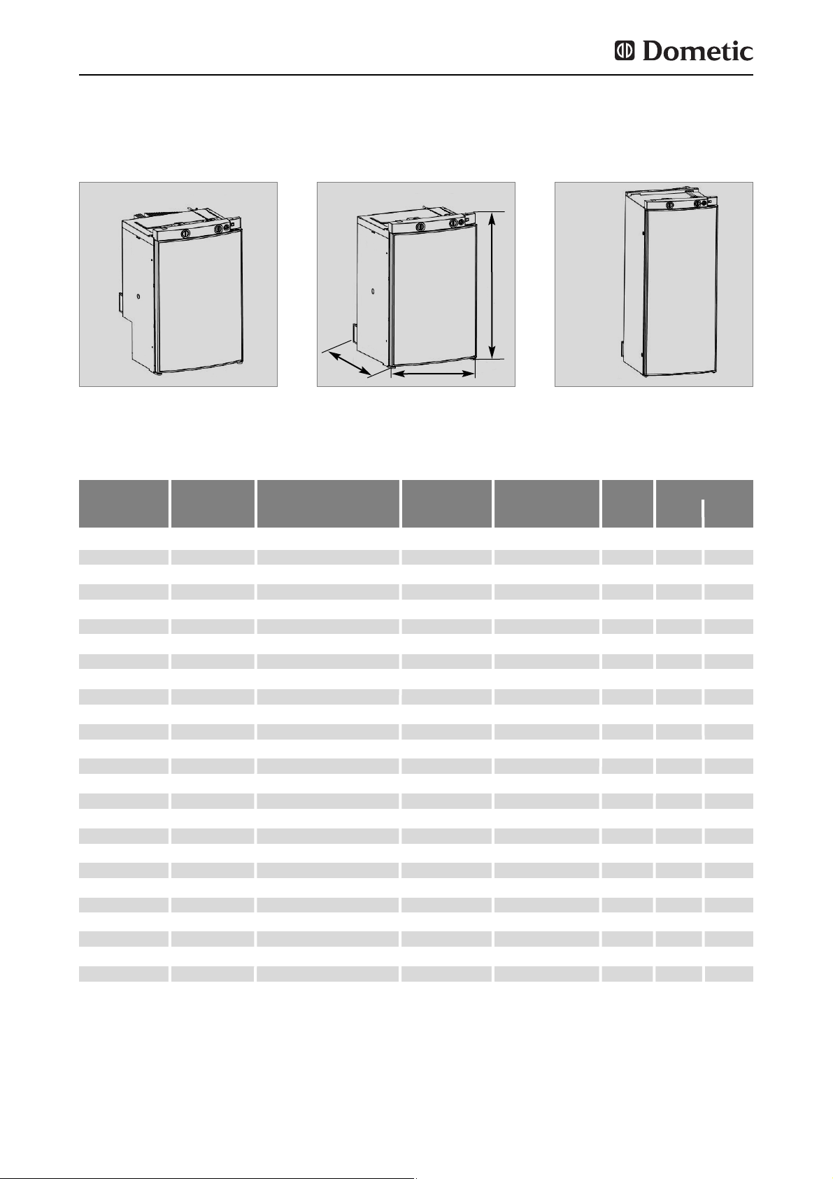
Abb. 3Abb. 2
RMS 8xxx
RM 8xxx
H
B
T
RML 8xxx
Abb. 4
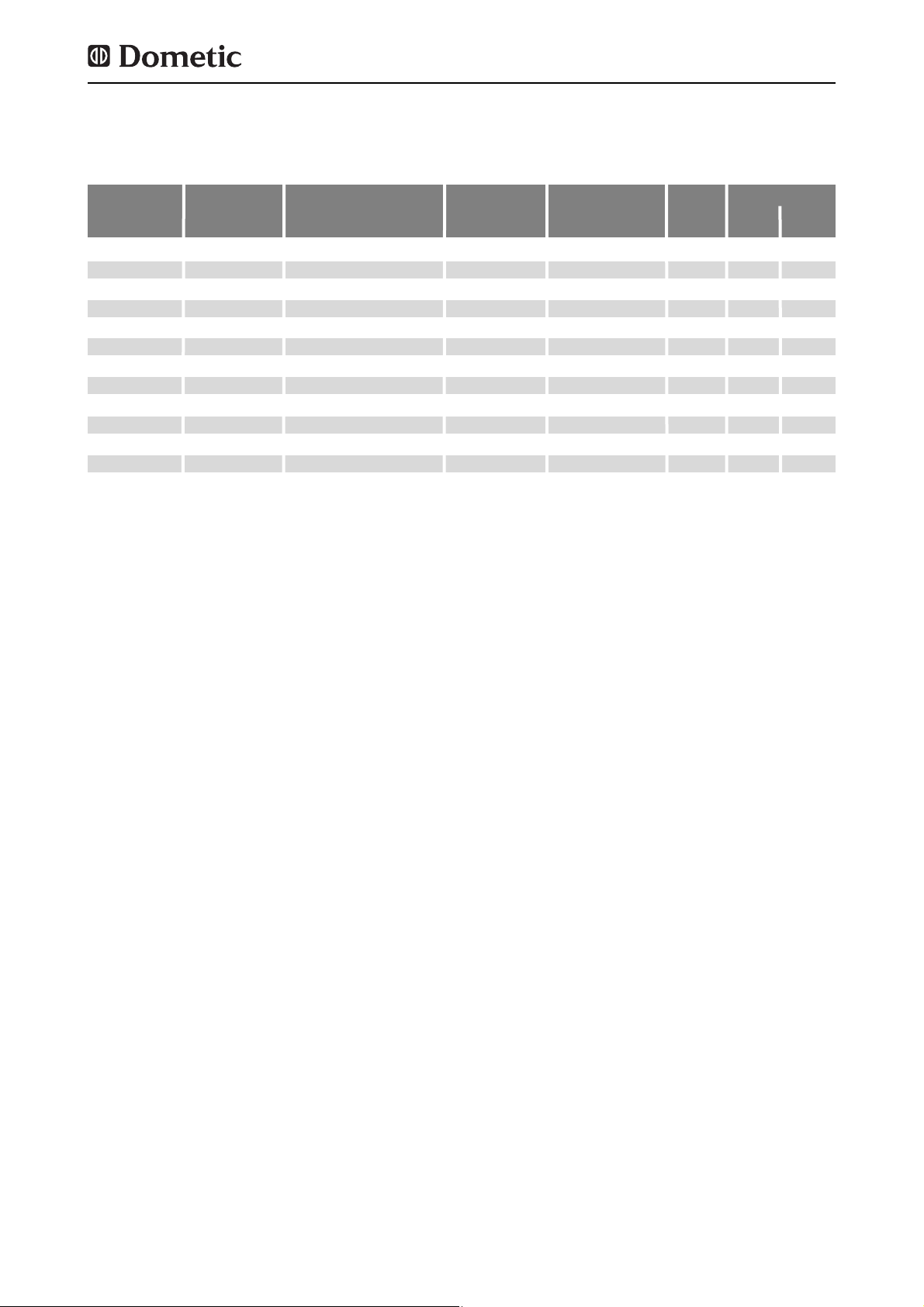
Modell Abmessungen Bruttoinhalt / Bruttoinhalt
Anschlusswerte
Verbrauch * Netto- Zündung
H x B x T (mm) mit Frosterfach Netz/Batterie Elektro/Gas gewicht Piezo Automat
Tiefe inkl. Tür Frosterfach entnommen in 24h
RMS 8400
RMS 8401
RMS 8405
RM 8400
RM 8401
RM 8405
RMS 8460
RMS 8461
RMS 8465
RMS 8500
RMS 8501
RMS 8505
RMS 8550
RMS 8551
RMS 8555
RM 8500
RM 8501
RM 8505
RM 8550
RM 8551
RM 8555
RML 8550
RML 8551
RML 8555
RMSL 8500
RMSL 8501
RMSL 8505
821x486x568
821x486x568
821x486x568
821x486x568
821x486x568
821x486x568
821x486x633
821x486x633
821x486x633
821x523x568
821x523x568
821x523x568
821x523x623
821x523x623
821x523x623
821x523x568
821x523x568
821x523x568
821x523x623
821x523x623
821x523x623
1245x523x625
1245x523x625
1245x523x625
1245x523x568
1245x523x568
1245x523x568
80 / 8 lit.
80 / 8 lit.
80 / 8 lit.
90 / 8 lit.
90 / 8 lit.
90 / 8 lit.
90 / 11 lit.
90 / 11 lit.
90 / 11 lit.
90 / 9 lit.
90 / 9 lit.
90 / 9 lit.
103 /12 lit.
103 /12 lit.
103 /12 lit.
100 / 9 lit.
100 / 9 lit.
100 / 9 lit.
115 /12 lit.
115 /12 lit.
115 /12 lit.
179 /33 lit.
179 /33 lit.
179 /33 lit.
145 /28 lit.
145 /28 lit.
145 /28 lit.
25 kg
25 kg
25 kg
27 kg
27 kg
27 kg
26 kg
26 kg
26 kg
26 kg
26 kg
26 kg
27 kg
27 kg
27 kg
28 kg
28 kg
28 kg
30 kg
30 kg
30 kg
45 kg
45 kg
45 kg
40 kg
40 kg
40 kg
85 lit.
85 lit.
85 lit.
95 lit.
95 lit.
95 lit.
96 lit.
96 lit.
96 lit.
96 lit.
96 lit.
96 lit.
110 lit.
110 lit.
110 lit.
106 lit.
106 lit.
106 lit.
122 lit.
122 lit.
122 lit.
189 lit.
189 lit.
189 lit.
155 lit.
155 lit.
155 lit.
125 W / 120 W
125 W / 120 W
125 W / 120 W
135 W / 130 W
135 W / 130 W
135 W / 130 W
125 W / 120 W
125 W / 120 W
125 W / 120 W
125 W / 120 W
125 W / 120 W
125 W / 120 W
125 W / 120 W
125 W / 120 W
125 W / 120 W
135 W / 130 W
135 W / 130 W
135 W / 130 W
135 W / 130 W
135 W / 130 W
135 W / 130 W
190 W / 170 W
190 W / 170 W
190 W / 170 W
190 W / 170 W
190 W / 170 W
190 W / 170 W
•
•
•
•
•
•
•
•
•
•
•
•
•
•
•
•
•
•
•
•
•
•
•
•
•
•
•
ca.2,5 KWh / 270 g
ca.2,5 KWh / 270 g
ca.2,5 KWh / 270 g
ca.2,4 KWh / 270 g
ca.2,4 KWh / 270 g
ca.2,4 KWh / 270 g
ca.2,5 KWh / 270 g
ca.2,5 KWh / 270 g
ca.2,5 KWh / 270 g
ca.2,5 KWh / 270 g
ca.2,5 KWh / 270 g
ca.2,5 KWh / 270 g
ca.2,6 KWh / 270 g
ca.2,6 KWh / 270 g
ca.2,6 KWh / 270 g
ca.2,4 KWh / 270 g
ca.2,4 KWh / 270 g
ca.2,4 KWh / 270 g
ca.2,6 KWh / 270 g
ca.2,6 KWh / 270 g
ca.2,6 KWh / 270 g
ca.3,2 KWh / 380 g
ca.3,2 KWh / 380 g
ca.3,2 KWh / 380 g
ca.3,2 KWh / 380 g
ca.3,2 KWh / 380 g
ca.3,2 KWh / 380 g
Modelle mit gebogener Tür
Page 9
9
Modellbeschreibung
Technische Änderungen vorbehalten.
*Durchschnittsverbrauch gemessen bei einer durchschnittlichen Umgebungstemperatur von 25°C in Anlehnung an ISO-
Standard.
Modell Abmessungen Bruttoinhalt / Bruttoinhalt
Anschlusswerte
Verbrauch * Netto- Zündung
H x B x T (mm) mit Frosterfach Netz/Batterie Elektro/Gas gewicht Piezo Automat
Tiefe inkl. Tür Frosterfach entnommen in 24h
RMS 8500
RMS 8501
RMS 8505
RMS 8550
RMS 8551
RMS 8555
RM 8500
RM 8501
RM 8505
RM 8550
RM 8551
RM 8555
821x523x541
821x523x541
821x523x541
821x523x596
821x523x596
821x523x569
821x523x541
821x523x541
821x523x541
821x523x596
821x523x596
821x523x596
86 / 9 lit.
86 / 9 lit.
86 / 9 lit.
99 /12 lit.
99 /12 lit.
99 /12 lit.
96 / 9 lit.
96 / 9 lit.
96 / 9 lit.
111 /12 lit.
111 /12 lit.
111 /12 lit.
26 kg
26 kg
26 kg
27 kg
27 kg
27 kg
28 kg
28 kg
28 kg
30 kg
30 kg
30 kg
92 lit.
92 lit.
92 lit.
106 lit.
106 lit.
106 lit.
102 lit.
102 lit.
102 lit.
118 lit.
118 lit.
118 lit.
125 W / 120 W
125 W / 120 W
125 W / 120 W
125 W / 120 W
125 W / 120 W
125 W / 120 W
135 W / 130 W
135 W / 130 W
135 W / 130 W
135 W / 130 W
135 W / 130 W
135 W / 130 W
•
•
•
•
•
•
•
•
•
•
•
•
ca.2,5 KWh / 270 g
ca.2,5 KWh / 270 g
ca.2,5 KWh / 270 g
ca.2,6 KWh / 270 g
ca.2,6 KWh / 270 g
ca.2,6 KWh / 270 g
ca.2,4 KWh / 270 g
ca.2,4 KWh / 270 g
ca.2,4 KWh / 270 g
ca.2,6 KWh / 270 g
ca.2,6 KWh / 270 g
ca.2,6 KWh / 270 g
Modelle mit flacher Tür
Page 10
10
4.0 Einbauanleitung
Das Gerät und die Abgasführung müssen
grundsätzlich so eingebaut werden, dass es
für Servicearbeiten gut zugänglich ist, leicht
aus- und eingebaut und ohne großen Aufwand
aus dem Fahrzeug entnommen werden kann.
Bei der Aufstellung und dem Anschluss des
Gerätes sind folgende Bestimmungen zu
beachten:
Die elektrische Installation muss nach
den nationalen und örtlichen Vorschiften
erfolgen.
Die Gas-Installation muss nach den
nationalen und örtlichen Vorschiften
erfolgen.
Europäische Norm EN 1949
Europäische Norm EN 60335-1,
EN 60335-2-24, EN 1648-1 , EN 1648-2
Installieren Sie das Gerät geschützt
gegen übermässige Wärmeeinstrahlung.
Überhöhte Wärmeeinstrahlung führt zu Leistungseinbußen und erhöhtem Energieverbrauch des Kühlschrankes !
4.1 Einbau
Abweichungen von dieser Einbauanweisung ohne vorherige Freigabe von Dometic
führen zum Erlöschen der Gewährleistung
seitens der Dometic GmbH !
Die Installation des Gerätes darf nur von
autorisiertem Fachpersonal erfolgen!
WARNUNG!
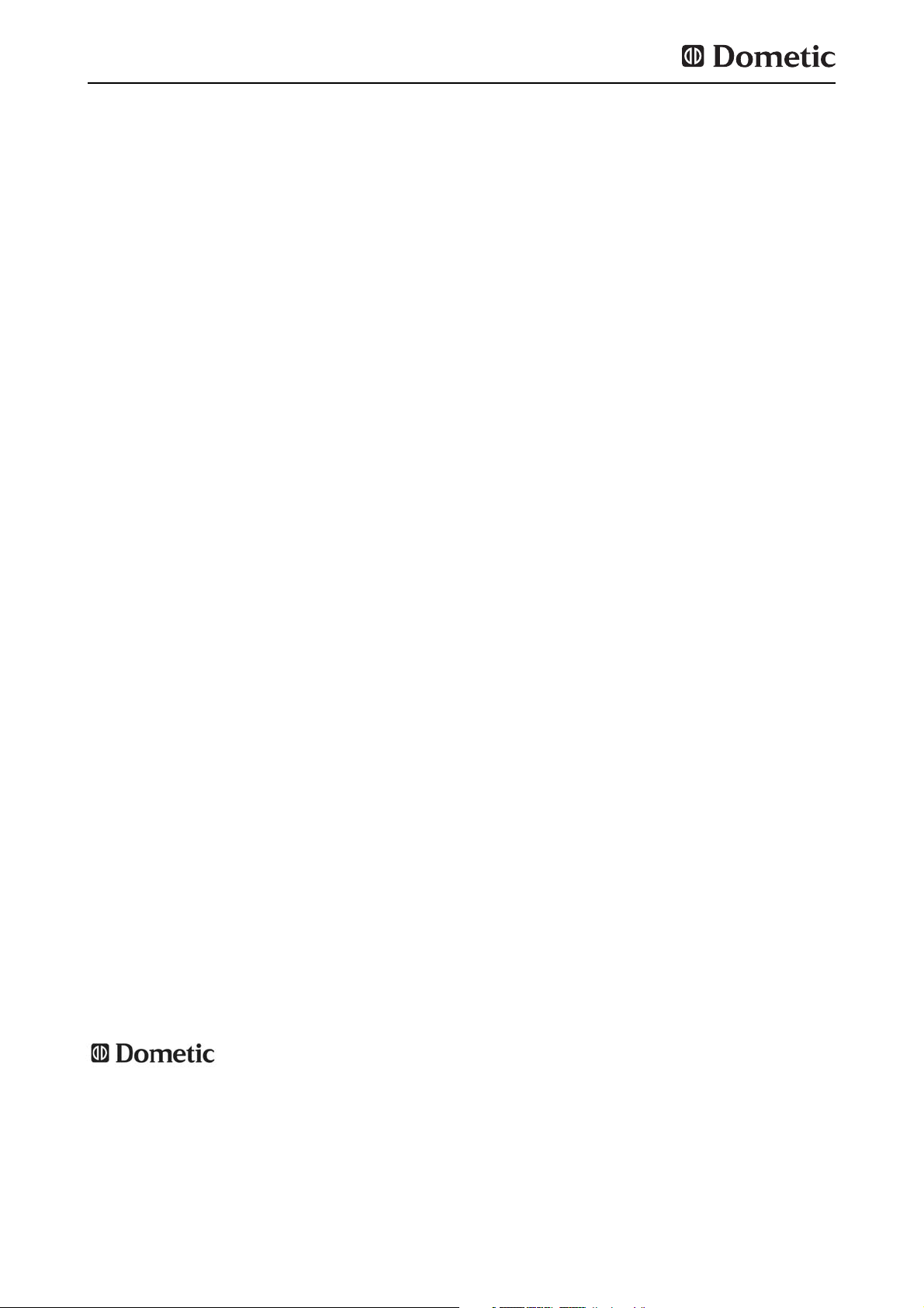
(Abb. 6) Die Lüftungsgitter bieten auch bei
geöffneter Tür einen ungehinderten Austritt
der Aggregatwärme und der Abgase.
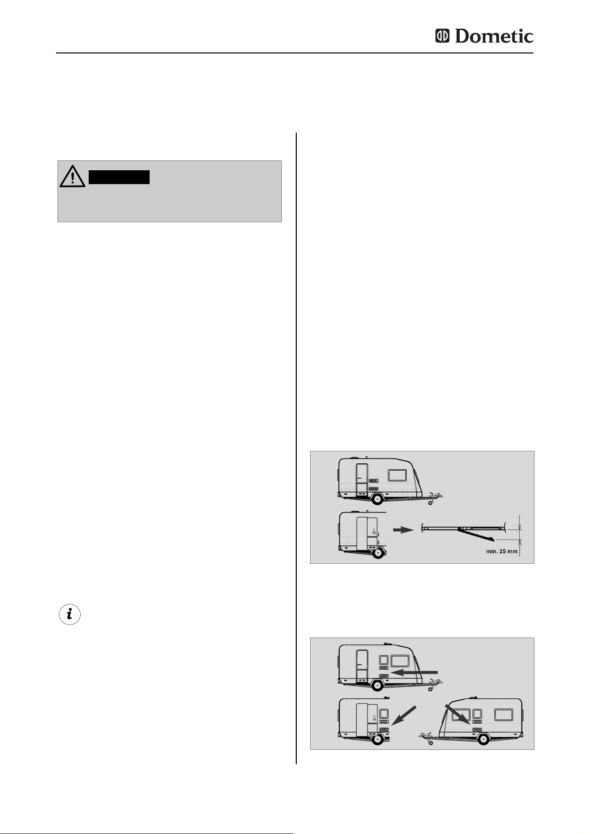
4.1.1 Seitlicher Einbau
Wird das Gerät auf der Seite der Eingangstür
eingebaut, ist darauf zu achten, dass die
Belüftungsgitter nicht durch die aufstehende
Tür zugedeckt werden. (
Abb. 5
Abstand Tür Belüftungsgitter min. 25 mm). Ansonsten entsteht eine eingeschränkte Belüftung, die zu
Kühlleistungsverlusten führt. Die Türseite des
Fahrzeugs wird oft mit einem Vorzelt versehen.
Dadurch wird die Ableitung von
Verbrennungsgasen und Wärme durch die
Lüftungsgitter erschwert (Kühlleistungsverlust entsteht)!
(Abb.5) Die Lüftungsgitter sind abgedeckt. Der
Abstand zwischen der Tür und den
Lüftungsgittern muss min. 25 mm betragen!
Bei Abständen Tür/Gitter zwischen 25 mm
und 45 mm empfehlen wir den Einbau des
Dometic Lüfterkits (
Artikel-Nr. 241 2985 -
00/0
) , um eine optimale Kühlleistung bei
hohen Umgebungstemperaturen zu erreichen.
Abb. 5
Abb. 6
Lüftungsgitter frei !
OK!
Einbau
Page 11
11
Abb. 7
Bodenöffnung:
min. 50 mm breit
min. 520 mm lang
Warmluft
Kondensator
Empfehlung:
Dachentlüfter
R500
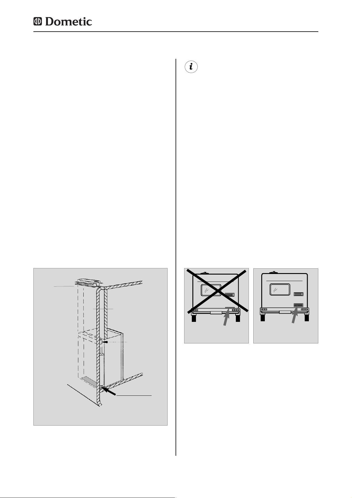
Eine weitere Möglichkeit ist, die Ventilation
des Kühlschranks über eine
Belüftungsöffnung im Boden und eine
Entlüftungseinrichtung auf dem Dach des
Fahrzeugs herbeizuführen (siehe Abb. 7).
Zwischen Oberkante Kühlschrank und
Dachentlüftung muss ein Kamin eingerichtet
sein, der die Warmluft und ggf. die Abgase des
Kühlschrankaggregates direkt zur Dachentlüftung leitet.
Die Bodenöffnung muss einen freien
Querschnitt von mindestens 250 cm² aufweisen. Die Öffnung muss mit einem Schutz, z.B.
Prellblech und Netz, versehen sein, um den
Eintritt von Schmutz in den Gasbrennerbereich zu verhindern. Bei dieser Belüftungsweise kann im Vergleich zur seitlichen
Belüftung mehr Schmutz in den rückwärtigen
Bereich des Kühlschranks eindringen, sodass
eine regelmäßige Wartung des Gasbrenners,
mind. einmal im Jahr, vorzusehen ist.
Bei dieser Einbauvariante ist die regelmäßige Wartung der Gasbrennereinheit nur
nach Ausbau des Gerätes möglich. Der
Kühlschrank muss zwingend in der Weise
installiert sein, dass ein leichter Ausbau
gewährleistet ist.
Wir empfehlen daher, eine Wartungsöffnung (Serviceklappe) an der Außenseite
vorzusehen.
4.1.2 Seitlicher Einbau mit BodenDach-Ventilation
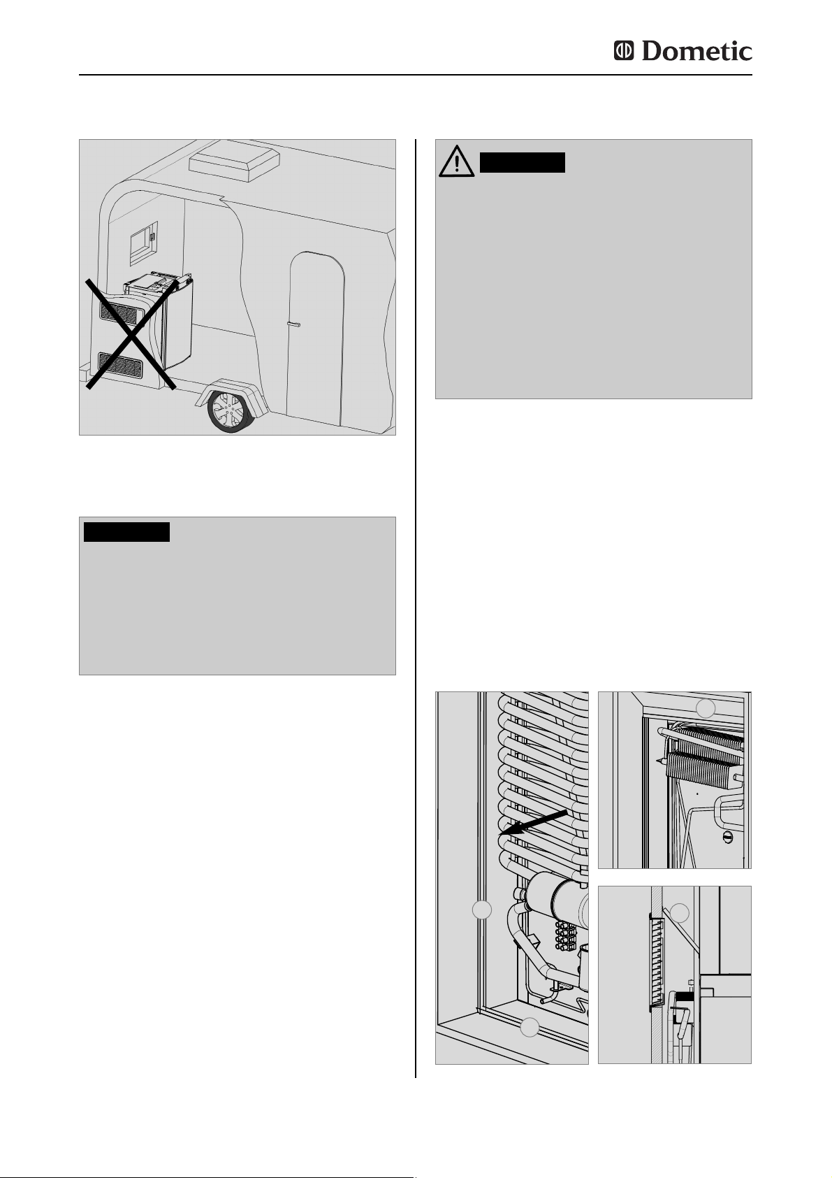
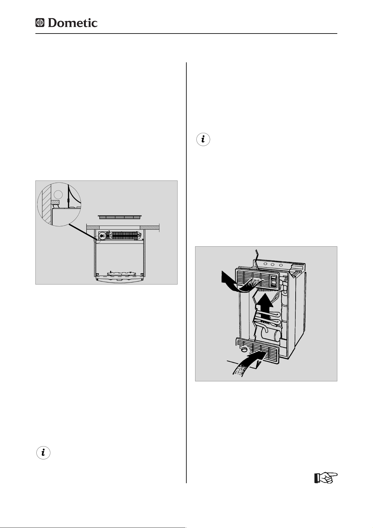
Eine ungünstige Variante des Heckeinbaus ist
die seitliche Anbringung der Be- und
Entlüftungsgitter (
Abb. 10
). Die Luft- Wärme Umwälzung ist sehr eingeschränkt, wodurch
die Wärmetauscher (Kondenser, Absorber)
nicht mehr ausreichend gekühlt werden. Auch
die Variante mit einem zusätzlich im Boden
montierten Belüftungsgitter weist hier eine
schlechte Luftstromführung auf.
Abb. 8
Abb. 9
Lüftungsgitter
frei ! OK!
Lüftungsgitter
nicht frei !
4.1.3 Heckeinbau
Der Heckeinbau führt oftmals zu einer ungünstigen Einbausituation, da die optimale Beund Entlüftung nicht immer gewährleistet ist
(z.B. wird das untere Lüftungsgitter durch den
Stoßfänger oder die Rückleuchten des
Fahrzeuges verdeckt !) (
Abb. 8
). Die maximale
Kühlleistung des Aggregates ist effektiv nicht
verfügbar.
Einbau
Page 12
12
Abb. 10
Die maximale Kühlleistung ist nicht verfügbar! Wenden Sie diese Einbaumöglichkeit nicht an, da bei dieser Einbausituation die Be- und Entlüftung wie unter
Punkt 4.2 beschrieben nicht gewährleistet ist!
VORSICHT!
4.1.4 Zugdichter Einbau
Kühlgeräte in Wohnwagen, Reisemobilen oder
sonstigen Fahrzeugen müssen zugdicht eingebaut sein (EN 1949). Das bedeutet, dass die
Verbrennungsluft für den Gasbrenner nicht aus
dem Wohnraum entnommen wird und die
Abgase am direkten Eintritt in den Wohnraum
gehindert werden.
Es muss eine geeignete Abdichtung zwischen
dem rückseitigen Bereich des Kühlschranks
und dem Fahrzeuginnenraum vorgesehen
werden.
Dometic empfiehlt dringend, dies mittels einer
flexiblen Dichtung auszuführen, um einen späteren Aus- und Einbau des Gerätes zu
Wartungszwecken zu vereinfachen.
In keinem Fall soll der zugdichte Einbau
des Kühlschranks mit dauerhaftenden
Dichtungsmassen oder Verschäumung
(z.B. Montageschaum) o. ä. erfolgen!
Verwenden Sie KEINE leicht entflammbaren Materialien (besonders SilikonDichtungsmasse oder ähnliches) zur
Abdichtung, es besteht Brandgefahr! Bei
deren Verwendung erlischt die Produkthaftung und Gewährleistung des
Geräteherstellers.
WARNUNG!
Die Lippendichtungen (1) werden in der
Einbaunische unten und jeweils seitlich angebracht (Abb. 11-13). Ein Wärmeableitblech (2)
wird in der Einbaunische oberhalb des Kühlschranks befestigt (NICHT am Kühlschrank
befestigen).
Bringen Sie das Ableitblech so an, dass die
erwärmte Luft durch das obere Lüftungsgitter
ins Freie entweicht und kein Wärmestau entstehen kann.
Abb. 12
Abb. 11
Abb. 13
1
1
2
2
Vorschlag 1
Einbau
Page 13

13
Der Raum, der sich zwischen Fahrzeugaussenwand und Kühlschrank befindet, ist gegenüber dem Wohnbereich abgedichtet. Es können keine Abgase in den Wohnbereich eindringen. Die Abgase entweichen durch das obere
Gitter der Be- und Entlüftung ins Freie. Es ist
beim zugdichten Einbau nicht erforderlich,
eine spezielle Abgasführung einzusetzen.
Bei dieser Einbauweise kann oben wie unten
das gleiche Lüftungsgitter LS200 ohne
Abgasführung eingesetzt werden.etic-Dicht-
Sollte dennoch ein Abgaskamin gewünscht
werden, bauen Sie in die obere Belüftungsöffnung das Belüftungssystem LS100 mit Abgasführung ein (
Einbau Abgaskamin siehe "4.4"
) .
Abweichungen bedürfen der Zustimmung
des Herstellers !
Bei hohen Umgebungstemperaturen ist die
volle Leistung des Kühlaggregates nur
durch eine ausreichende Be- und Entlüftung gewährleistet.
Der korrekte Einbau des Gerätes ist für die
Funktion wichtig, da sich auf der Rückseite
des Gerätes, physikalisch bedingt, Wärme
entwickelt, die ins Freie abgeleitet werden
muss.
4.2 Be- und Entlüftung des
Kühlschranks
Der Kühlschrank wird später von vorne in die
Einbaunische eingeschoben. Achten Sie darauf, dass die Dichtungen gleichmäßig am
Gehäuse anliegen.
Der Ausbau des Kühlschranks zur Wartung
und Reparatur ist so leicht möglich.
Abb. 14
Befestigen Sie die Dichtlippen an einer rückseitigen Anschlagsleiste (1), z.B. durch
Kleben.
1
Vorschlag 2
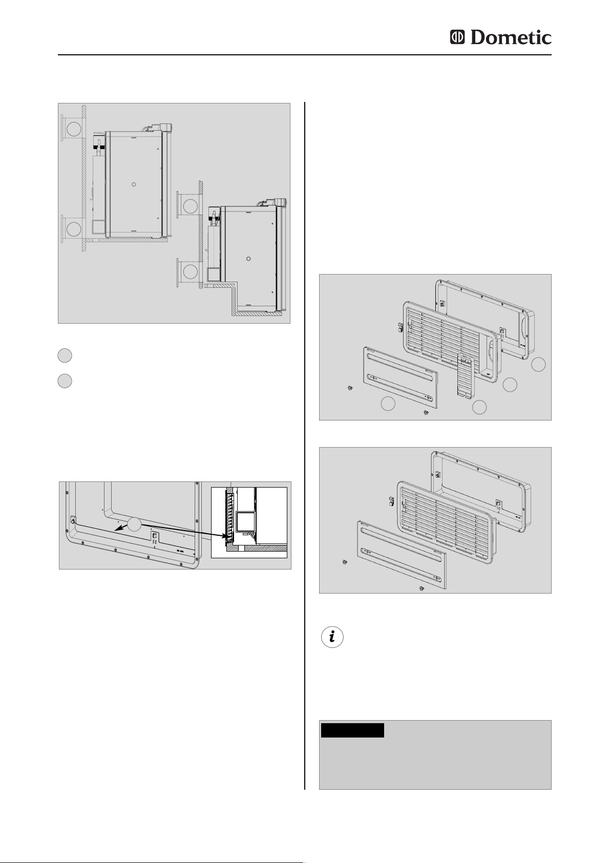
Die Belüftung des Aggregates erfolgt durch
zwei Öffnungen (Belüftungsgitter) in der
Fahrzeugwand. Frischluft tritt unten ein,
erwärmt sich und strömt durch das obere
Belüftungsgitter ab (Kamineffekt).
Das obere Belüftungsgitter sollte so hoch
wie möglich über dem Kühlaggregat angebracht werden (1, Abb. 16) . Das untere
Belüftungsgitter muss bündig mit dem
Nischenboden angeordnet sein (Abb.
16,17), damit unverbranntes Gas (schwerer
als Luft) auf direktem Weg ins Freie gelangt.
Einbau
Abb. 15
Page 14
Eine abweichende Installation vermindert
die Kühlleistung und gefährdet die
Gewährleistung/Produkthaftung.
VORSICHT!
14
Die korrekte Anbringung des unteren Lüftungsgitters erleichtert den Zugang zu
Geräteanschlüssen und Funktionsteilen bei
Wartungsarbeiten.
Abb. 16
1
2
1
2
Lüftungsgitter LS 100 oder LS 200
Lüftungsgitter LS 200
2
1
Abb. 18
Abb. 19
Das obere Lüftungssystem LS 100 besteht
aus einem Einbaurahmen (RS 1640) (1), einem
Lüftungsgitter inkl. Abgasführung (AS 1620)
(2, 3) und einer Winterabdeckung (WA120) (4).
Das untere Lüftungssystem LS 200 besteht
ebenfalls aus einem Einbaurahmen (RS 1650),
Lüftungsgitter (AS 1630, jedoch ohne
Abgasführung) und einer Winterabdeckung
(WA130).
4.3 Einbau der Lüftungssysteme
LS 100
LS 200
1
2
3
4
Einbau
Wenn diese Anordnung nicht möglich ist,
muss der Fahrzeughersteller eine Entlüftungsöffnung im Nischenboden herstellen,
damit unverbranntes Gas sich nicht am
Boden sammelt.
Die Belüftungsgitter müssen einen freien
Querschnitt von mindestens 250 cm² aufweisen. Dies wird mit dem Dometic Absorber
Be- und Entlüftungssystemen LS 100 / LS 200
erreicht, die für diesen Zweck geprüft und
zugelassen sind.
Abb. 17
1
Der Gasbrenner muss sich oberhalb der
Kante (1, Abb. 17) befinden.
Page 15

15
Abb. 20
Abb. 24
Einbaurahmen wasserundurchlässig abdichten
(
entfällt beim
Einbaurahmen mit integrierter Dichtung
).
1
Abb. 21
Rahmen einsetzen und
festschrauben.
2
Zum Einbau der Belüftungsgitter werden zwei
rechteckige Ausschnitte in der Größe von 451
mm x 156 mm in der Fahrzeugaußenwand
angebracht (
Lage der Ausschnitte siehe Pkt.
4.2
).
Abb. 22
Lüftungsgitter einsetzen
und verriegeln.
3
Abb. 23
Einsatz für Abgasführung
einclipsen (
nur bei oberem Entlüftungssystem
LS100
).
4
Winterabdeckung einsetzen.
5
Die Abgasführung muss so gestaltet sein,
dass die vollständige Ableitung der Verbrennungsprodukte nach außerhalb des Wohnraumes sichergestellt ist. Die Abgasleitung
muss stetig steigend geführt werden, um eine
Ansammlung von Kondensat zu vermeiden.
Bei der in Abb. 25 gezeigten Art der
Abgasführung wird die Winterabdeckung seitlich (10) (Abb. 25) angebracht.
4.4 Abgasführung und
Anbringen des Abgaskamins
Anbringen des Standardabgaskamins
1. T-Stück (1) auf den Adapter (2), bzw. auf
das Abgasrohr (3) aufstecken und mit der
Schraube (4) fixieren. Dabei ist darauf zu achten, dass der Heizverteiler (5) in der dafür vorgesehenen Position sitzt.
2. Abgasrohr kpl. mit Abdeckplatte (6) durch
die dafür vorgesehene Öffnung des oberen
Rahmens (7) stecken und mit dem T-Stück (1)
verbinden. Abgasrohr (6) eventuell auf richtige
Länge kürzen.
3. Lüftungsgitter LS 100 (8) in den Einbaurah-
men (7) einsetzen und verriegeln.
4. Abdeckkappe (9) auf das Abgasrohr (6)
stecken.
5. Einsatz für Abgasführung (10) in das
Lüftungsgitter (8) einsetzen.
Einbau
Abb. 25
1
2
3
4
5
6 79
10
8
min. 15mm
Page 16
16
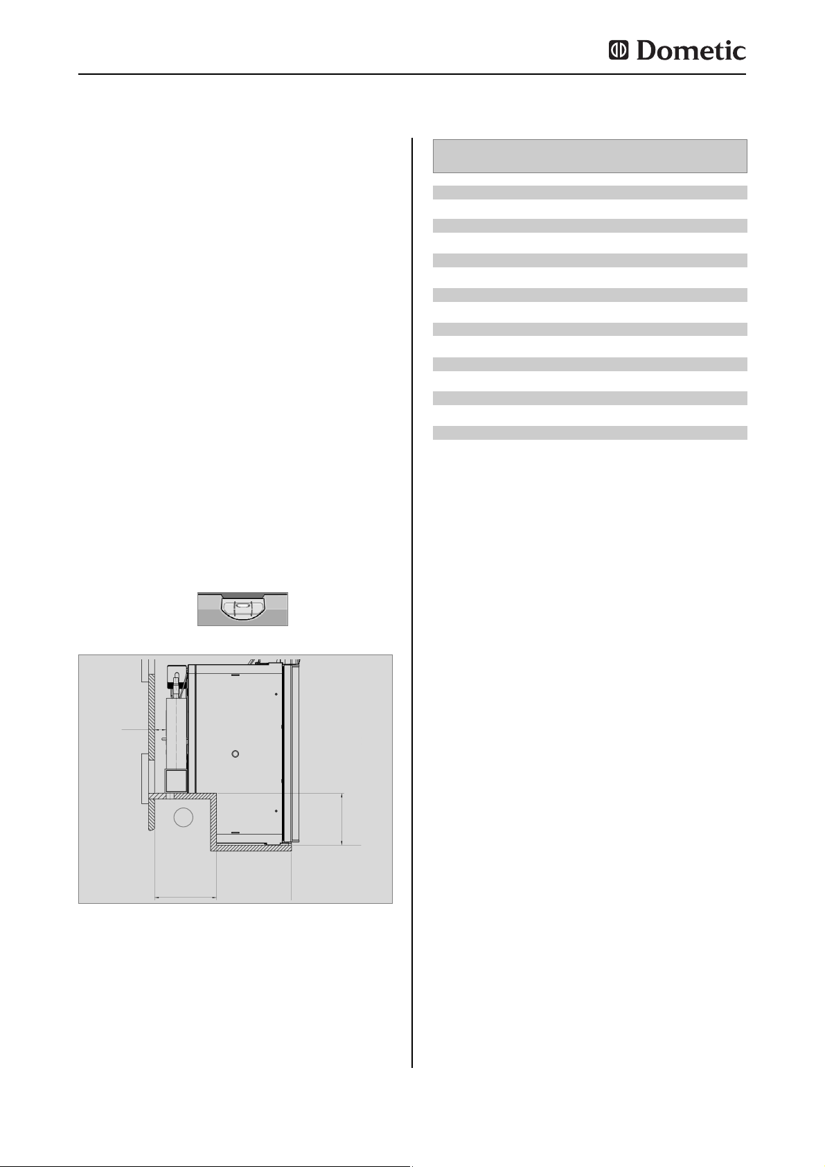
4.5.1 Aufstellen in der Nische
Das Gerät wird in die Nische soweit eingeschoben, bis Vorderkante des Kühlschrankgehäuses und Vorderkante Nische fluchten.
Zwischen Nischenrückwand und Kühlschrankaggregat sollen 15-20 mm Freiraum
sein!
Der Kühlschrank muss waagerecht in die
Nische eingebaut werden.
Der Kühlschrank muss in eine Nische zugdicht eingebaut werden (s.a. "4.1.4"). Die
Stufe (1) (Abb. 26) wird nur bei
Stufenschränken benötigt. Der Nischenboden
muss eben sein, sodass das Gerät sich leicht
in seine richtige Lage einschieben lässt. Der
Boden muss genügend Festigkeit haben um
das Gewicht des Gerätes tragen zu können.
4.5 Einbaunische
Einbau
Abb. 26
T
ST
min
15-20mm
H
ST
1
Modell Höhe H
ST
Tiefe T
ST
RMS 8400
RMS 8401
RMS 8405
RMS 8460
RMS 8461
RMS 8465
RMS 8500
RMS 8501
RMS 8505
RMS 8550
RMS 8551
RMS 8555
RMSL 8550
RMSL 8551
RMSL 8555
220 mm
220 mm
220 mm
220 mm
220 mm
220 mm
220 mm
220 mm
220 mm
220 mm
220 mm
220 mm
220 mm
220 mm
220 mm
235 mm
235 mm
235 mm
235 mm
235 mm
235 mm
235 mm
235 mm
235 mm
235 mm
235 mm
235 mm
235 mm
235 mm
235 mm
Page 17
17
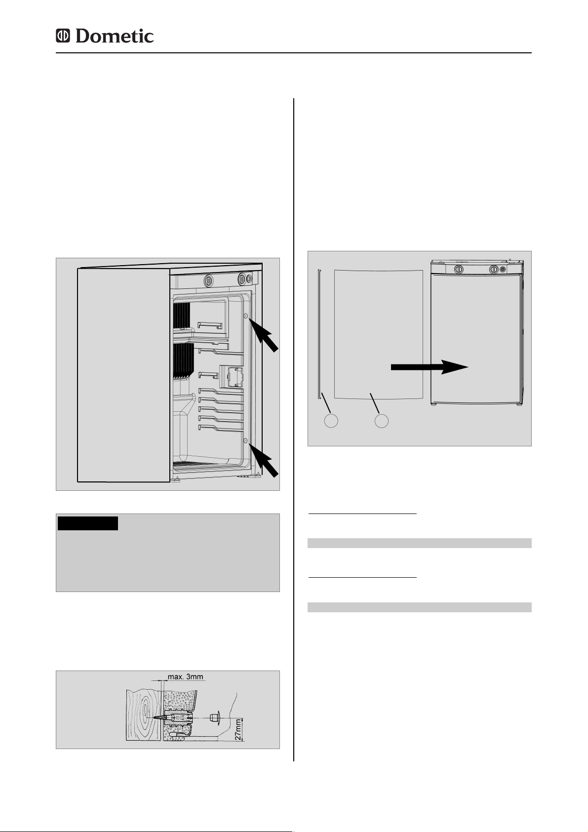
Nachdem der Kühlschrank in seine endgültige
Lage gebracht ist, werden die Schrauben
durch das Gehäuse des Kühlschrankes in die
Nischenwand geschraubt.
Abb. 27
Abb. 28
In den Seitenwänden des Kühlschrankes sind
vier Kunststoffbuchsen zur Befestigung des
Kühlschrankes vorgesehen. Die Seitenwände
oder die zur Kühlschrankbefestigung angebrachten Leisten müssen so ausgelegt sein,
dass die Schrauben auch bei erhöhter
Beanspruchung (während der Fahrt) fest sitzen. Befestigungsschrauben und Abdeckkappen liegen dem Kühlschrank bei.
4.6 Kühlschrankbefestigung
Schrauben immer durch die dafür vorgesehenen Buchsen drehen, da ansonsten
eingeschäumte Bauteile wie Leitungen u.
a. beschädigt werden können.
VORSICHT!
4.7 Einsetzen der Dekorplatte
Ziehen Sie die seitliche Leiste (1) der Tür ab
( Leiste ist aufgesteckt, nicht verschraubt)
Schieben Sie die Dekorplatte (2) in die Tür
ein und stecken Sie die Leiste (1) wieder
auf.
Abb. 29
Modell RM 8xxx, RMS 84xx
Abmessungen der Dekorplatte :
743 +/- 0.5 mm 472 +/- 0.5 mm max. 2.2 mm
Gehäusebr
eite 486 mm
Höhe Breite Dicke
743 +/- 0.5 mm 510.5 +/- 0.5 mm max. 2.2 mm
Gehäusebr
eite 523 mm
Höhe Breite Dicke
2
1
Einbau
Page 18

18
Einbau
Abb. 31
Abb. 32
Modell RM 8xxx, RMS 84xx
Abmessungen der Dekorplatte RML 8xxx:
1169,5 +0/-1 mm 507,5 +0/-1 mm max. 1.7 mm
Gehäusebr
eite 525 mm
Höhe Breite Dicke
VORSICHT!
Abb. 33
Abb. 35
Abb. 36
Abb. 34
Modell RMx(L) 8xxx, rahmenlose
Dekorplatte
1
2
3
4
Abb. 30
1
2
1.
1.
2.
2.
3.
4.
Page 19
19
Einbau
Beachten Sie die in Punkt 4.1 aufgeführ-
ten Bestimmungen !
Dieser Kühlschrank ist für eine
Installation in eine Flüssigasanlage nach
EN1949 vorgesehen und muss ausschließlich mit Flüssiggas (Propan,
Butan) betrieben werden (kein Erdgas,
Stadtgas) .
Ein fest eingestellter Druckregler nach
EN 12864 ist an dem Flüssiggasbehälter
anzuschliessen.
Der Druckregler muss mit dem auf dem
Typenschild des Gerätes angegebenen
Betriebsdruck übereinstimmen. Der Betriebsdruck entspricht dem Normdruck
des Bestimmungslandes (EN 1949, EN
732).
Für ein Fahrzeug ist nur ein einheitlicher
Anschlussdruck zulässig! Ein Hinweisschild mit dem dauerhaften, gut lesbaren
Hinweis auf den Betriebsdruck ist am
Aufstellungsort der Gasflasche gut
sichtbar anzubringen.
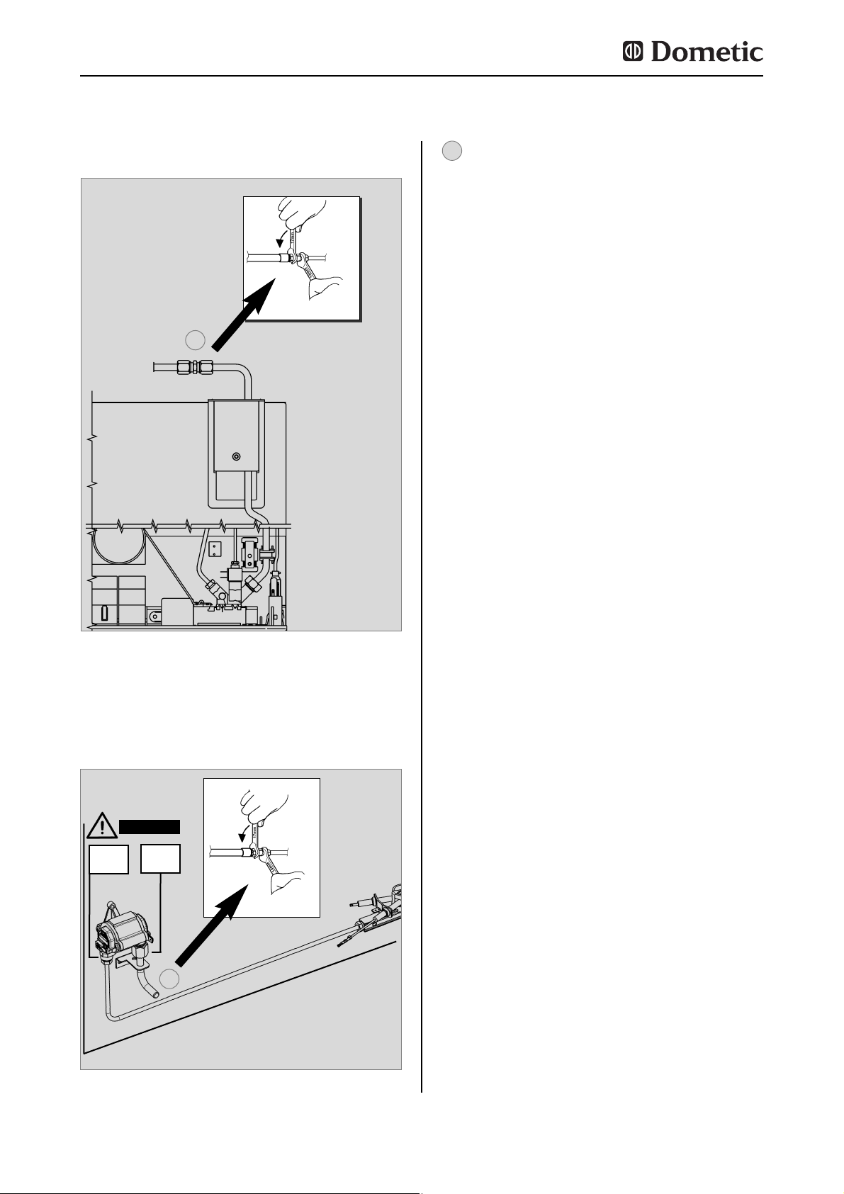
Der Gasanschluss zum Gerät muss mit
Rohranschlussleitungen fest und spannungsfrei installiert und mit dem Fahrzeug fest verbunden sein (Schlauchanschluss ist unzulässig) ( EN 1949 ).
Der Gasanschluss am Gerät erfolgt mit
tels einer Schneidring- (Ermeto-)
Verschraubung L8, DIN 2353-ST nach EN
1949 (siehe Abb. 37,38).
Nach fachgerechter Installation ist eine
Dichtheitsprüfung und eine Flammprobe
* Autorisierte Fachkräfte sind anerkannte Sachkundige,
die aufgrund ihrer Ausbildung und Kenntnisse die
Gewähr dafür bieten, dass die Installation und die
Dichtheitsprüfung ordnungsgemäß durchgeführt wird.
gemäß EN 1949 von einer autorisierten
Fachkraft* durchzuführen. Über die
Prüfung ist eine Bescheinigung auszu stellen.
Der Kühlschrank muss durch eine Ab-
sperreinrichtung in der Zuführungsleitung absperrbar sein. Die Absperreinrichtung muss für den Benutzer leicht
zugänglich angebracht werden.
4.8 Gasinstallation
Der Gasanschluss darf nur von einer autorisierten Fachkraft* ausgeführt werden.
WARNUNG!
Dometic Kühlschränke dieser Serie sind für
den Anschlussdruck 30 mbar ausgerüstet.
Verwenden Sie bei einem Anschluss an eine
50 mbar-Anlage den Truma Vordruckregler
VDR 50/30.
Bei der Verwendung von Autogas ist zu
beachten, dass aufgrund der Art der
Verbrennung des Gases der Brenner häufiger
gereinigt werden muss ( 2-3 Mal im Jahr empfohlen).
Anschlussdruck und Gaskategorien
Die Kühlschränke werden mit den nachfolgend angegebenen Gasen und Einlassdrükken betrieben. Die zwischen Gasflasche und
Kühlschrank einzusetzenden Druckminderer
müssen den in der nachfolgenden Tabelle
angegebenen Kategorien entsprechen.
Kategorie Druck in mbar GAS
I3B / P(30) 30 Butan
30 Propan
I3+ (28-30/37) 28-30 Butan
37 Propan
Page 20
20
Einbau
Abb. 38
SW 14
SW 17
VORSICHT!
20 Nm
max
10 Nm
max
Gasanschluss
Modelle RM(S)(L) 8xx1, RM(S)(L) 8xx5
Abb. 37
Gasanschluss Modelle RM(S)(L) 8xx0
SW 14
SW 17
Schneidring- (Ermeto-) Verschraubung L8,
DIN 2353-ST (EN ISO 8434)
1
1
1
Page 21
21
Die elektrische Installation muss nach
den nationalen Ländervorschriften erfolgen.
Die Anschlusskabel müssen so verlegt
sein, dass sie mit heissen Teilen des
Aggregates / Brenners oder mit scharfen
Kanten nicht in Berührung kommen.
Veränderungen an der internen elektri-
schen Installation oder der Anschluss
anderer elektrischer Komponenten (z. B.
fremder Zusatzlüfter) an der internen
Verkabelung des Gerätes führen zum
Erlöschen der e1/CE - Zulassung sowie
jeglicher Ansprüche aus Gewährleistung
und Produkthaftung !
* Autorisierte Fachkräfte sind anerkannte Sachkundige,
die aufgrund ihrer Ausbildung und Kenntnisse die
Gewähr dafür bieten, dass die Installation ordnungsgemäß durchgeführt wird.
4.9 Elektrische Installation
Die elektrische Installation darf nur von
einer autorisierten Fachkraft* ausgeführt
werden.
WARNUNG!
4.9.1 Netzanschluss
Die Stromversorgung muss an eine vor-
schriftsmäßig geerdete Steckdose oder
an einen geerdeten Festanschluss erfolgen. Wird die Netzanschlussleitung mit
Stecker verwendet, muss der Stecker
frei zugänglich sein.
Wenn die Anschlussleitung beschädigt
wird, muss sie durch den Kundendienst
von Dometic oder durch ebenso qualifiziertes Personal ersetzt werden, um
Gefährdungen zu vermeiden.
Wir empfehlen, die Zuleitung über eine bordseitige Absicherung zu führen.
Einbau
Abb. 42
4.9.2 Batterieanschluss
Das bordseitige 12V-Anschlusskabel wird an
eine Klemmleiste (RMx 8xx0) oder an
Steckkontakten (RMx 8xx1, 8xx5) am
Kühlschrank polrichtig angeschlossen. Die
Verkabelung für das 12V-Heizelement (s.
Schaltbild Anschluss A, B) sollte mit einer
direkten, möglichst kurzen Verbindung an die
Batterie bzw. Lichtmaschine erfolgen.
Leitungsquerschnitte / Leitungslängen :
Motorcaravan & Caravan (innerhalb)
4 mm² (RML 8xxx = 6 mm²)< 6 m
6 mm² (RML 8xxx = 10 mm²)> 6 m
Caravan (außerhalb)
min 2,5 mm²(EN1648-1)
2,5mm²
Bordseitig ist der 12V-Stromkreis mit einer
20A Sicherung abzusichern.
Damit beim Abstellen des Fahrzeugmotors
nicht vergessen wird, den 12V-Betrieb auch
auszuschalten (die Batterie würde in wenigen
Stunden entladen), ist die Stromversorgung für
das 12V-Heizelement (s. Schaltbild Anschluss
A/B) so auszuführen, dass sie beim Umdrehen
des Zündschlüssels unterbrochen wird.
An dem Anschluss C/D (s. Schaltbild
Anschluss Beleuchtung, Elektronik) muss eine
12V-Dauerversorgung anliegen, die bordseitig
mit einer 2A - Sicherung abgesichert sein
muss.
Bei Installation im Caravan dürfen caravanseitig die jeweiligen Minus- und
Plusleitungen der 12V-Anschlüsse A/B
und C/D nicht miteinander verbunden
werden ( EN 1648-1).
VORSICHT!
Page 22
22
4.9.3 Kabelanschlüsse
Der Anschluss der Spannungsversorgungen
für Elektronik und Heizelemente erfolgt direkt
an den Steckkontakten der Elektronik.
Zum Betrieb der Gerätetypen MES und AES
ist es unerlässlich, eine 12V DC
Dauerversorgung an den Klemmen C/D
anzuschließen (Dauerversorgung für die
Funktionselektronik).
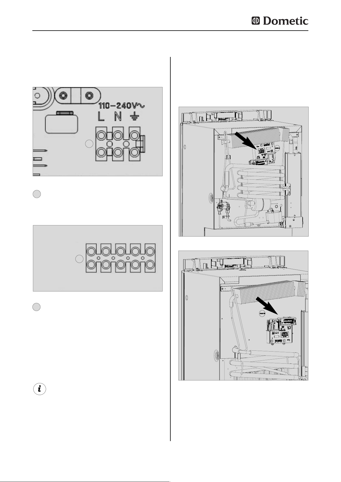
Anschlüsse bei Modellen RM(S) 8xx0 :
Anschlüsse bei Modellen RM(S) 8xxx (MES),
RM(S) 8xx5 (AES) :
Abb. 39
A = Masse Heizelement DC (braun)
B = Plus Heizelement DC (braun)
C = Minus Beleuchtung (schwarz)
D = Plus Beleuchtung (weiß)
Abb. 40
2
2
L = braun
N = blau
Erdung = gelb/grün
1
1
A
B
C
D
-
+
-
+
Netzanschluss
12V-Anschluss
fahrzeugseitig
geräteseitig
Einbau
Fig. 41
Position der Steuerelektronik :
Stufenschrankmodelle
Fig. 42
Standardmodelle
Page 23
23
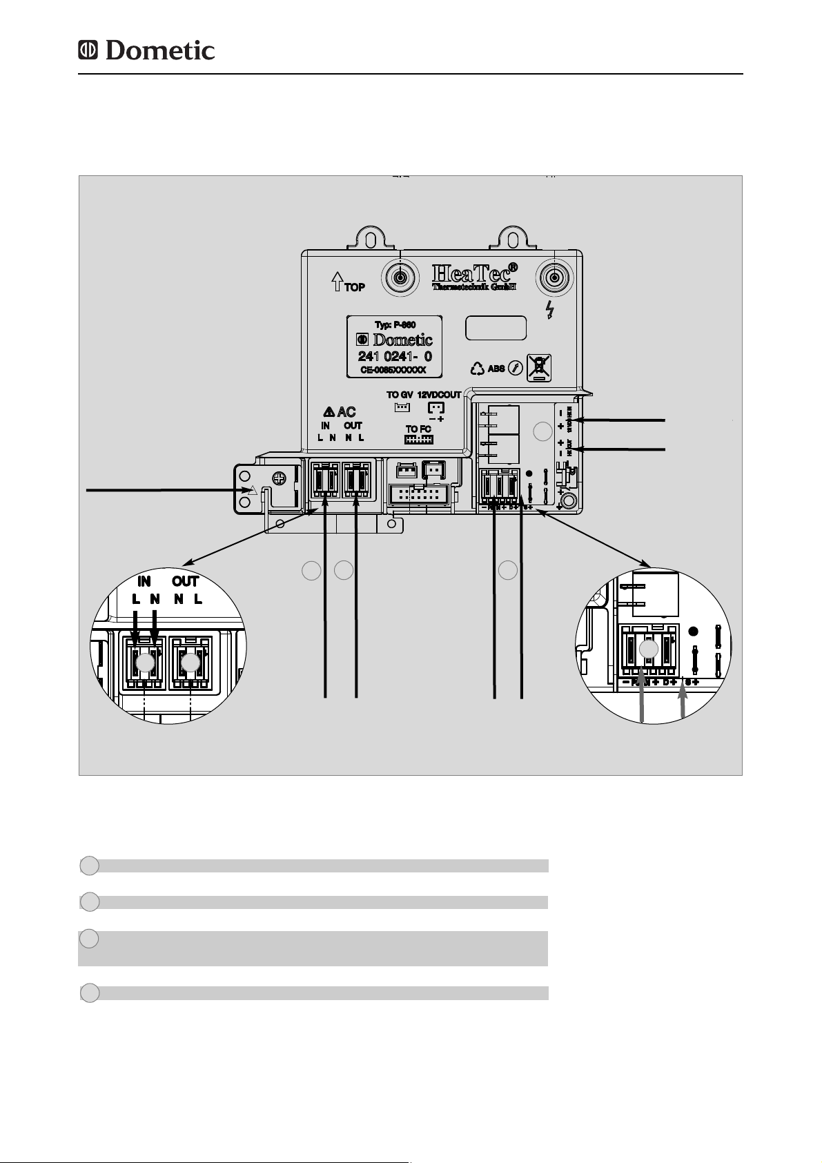
Abb. 43
Kontakte an der Elektronik :
Erdung
Anschluss Netz (230V~)
EINGANG
Heizelement (12V-)
AUSGANG
Heizelement (12V-)
Anschluss Elektronik (12V)
Anschluss D+ Signal
Anschluss S+ Signal
Heizelement Netz (230V~)
2
3
4
1
Steckkontakte (Hersteller : Stocko®)
MF 9562-002-80E
MF 9562-002-8 OC
3-polig mit D+ - Kontakt :
MF 9562-003-8 30 960-000-00
2-polig :
MF 9562-002-8 ON + Flachstecker 6.3 x 0.8
MKH 5132-1-0-200
2
1
3
4
Einbau
2
1
3
-
+
D+/S+
Page 24
24
Einbau
4.9.4 D+ und Solaranschluss (nur bei
AES-Modellen)
D+ - Anschluss:
Im >Automatic mode< wählt die AES-
Elektronik automatisch die günstigste vorhandene Energieart aus. Im Automatikmodus
nutzt die Elektronik das Signal D+ (Dynamo +)
der Lichtmaschine zur Erkennung von 12V
DC. Der Betrieb auf der Energieart 12V DC
wird nur angewählt, wenn der Fahrzeugmotor
läuft, um ein Entladen der Batterie zu vermeiden.
S+ - Anschluss:
Alternativ kann die Energieart 12V DC über
eine fahrzeugeigene Solaranlage eingespeist
werden. Die Solaranlage muss über einen
Solarladeregler mit AES-Ausgang verfügen
(entsprechende Laderegler sind im
Fachhandel erhältlich). Der Anschluss S+
(Solar +) muss mit der entsprechenden
Klemme des Solarladereglers (AES-Ausgang)
verbunden werden. Die Elektronik nutzt das
Signal S+ des Solarladereglers zur Erkennung
von 12V DC solar.
Kabelquerschnitte:
Über die D+ und S+ Verbindung fließt kein
hoher Strom, deshalb muss für diese
Verbindungen kein besonders großer
Querschnitt eingesetzt werden (ca. 1mm²
ausreichend).
Page 25
25
Einbau
Abb. 44
Schaltschema RM(S) 8xx0 :
4.9.5 Schaltschemata
A B C D
Page 26
26
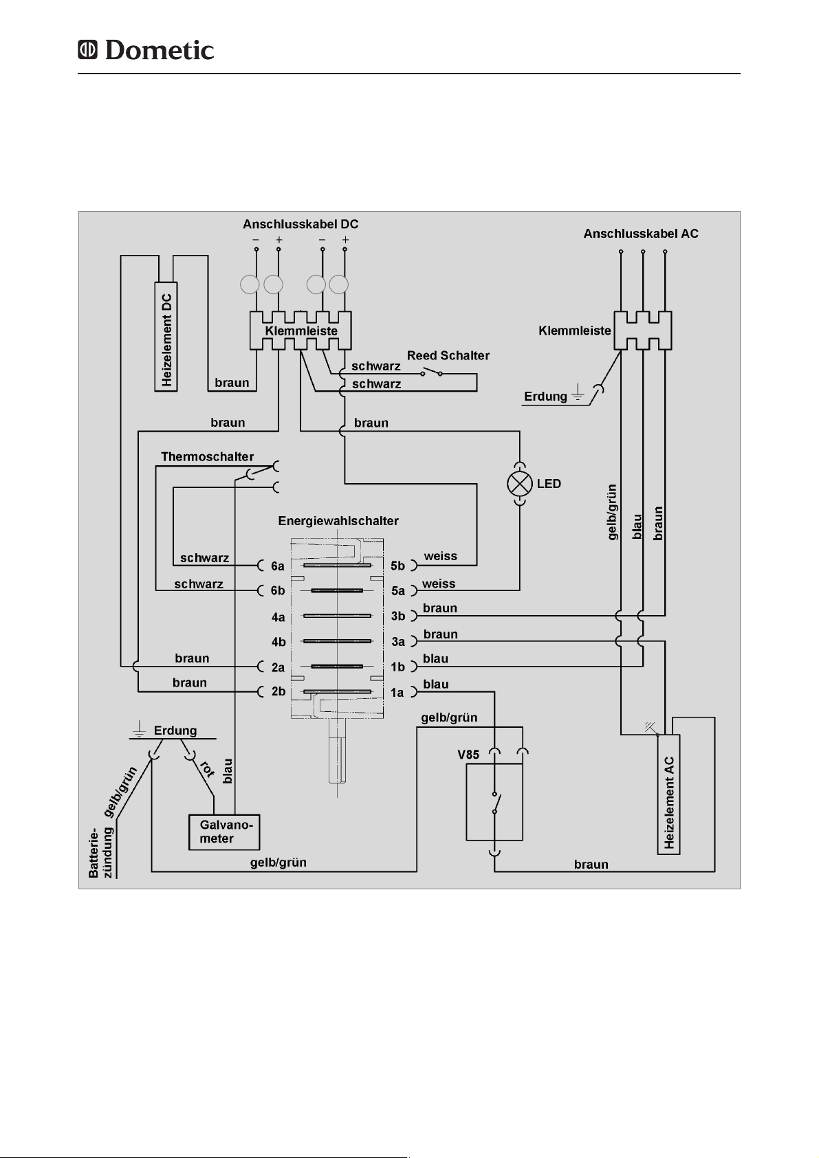
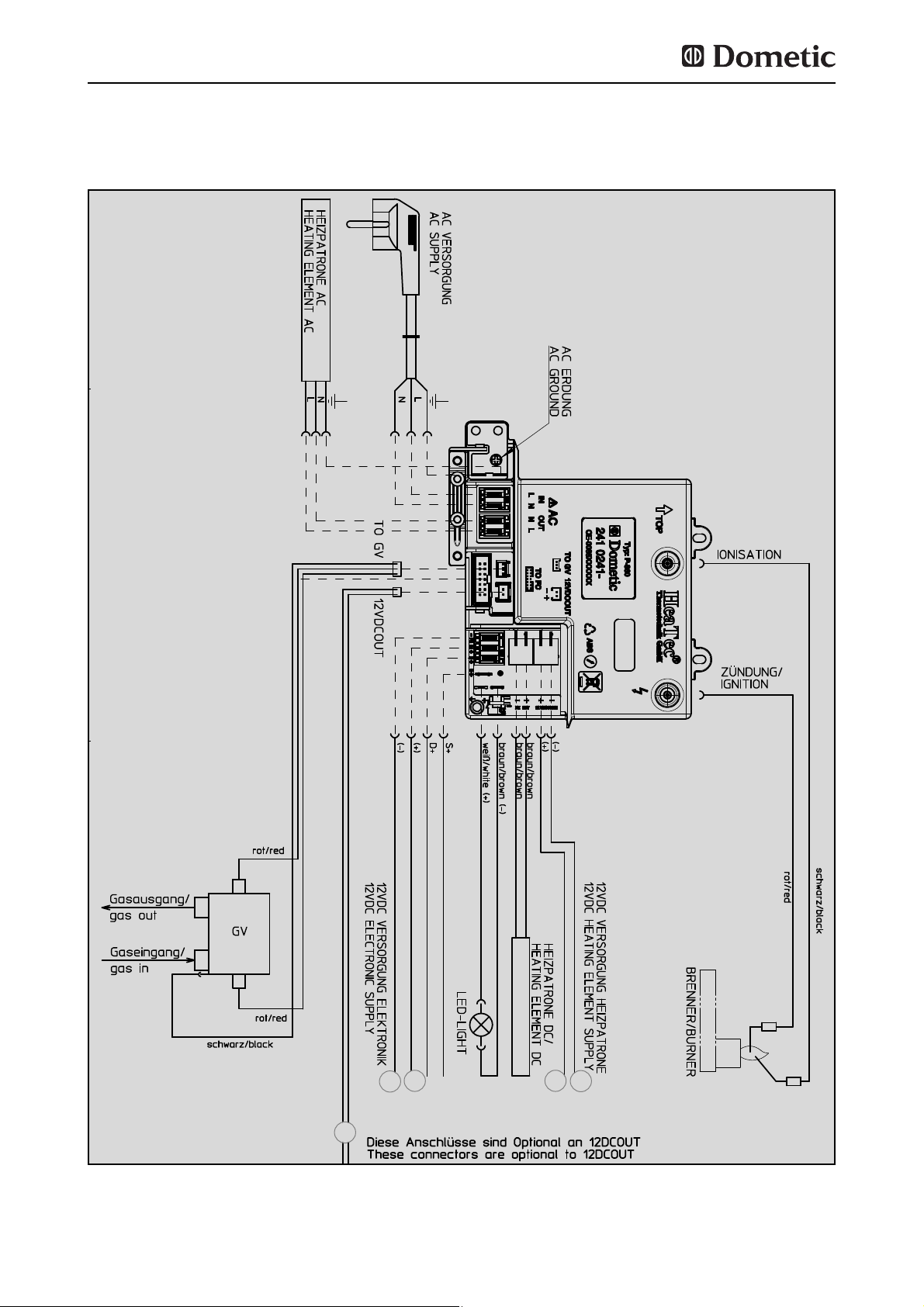
Schaltschema RM(S) 8xx1, RM(S) 8xx5 :
Einbau
Abb. 45
1
C
D B
A
Page 27
27
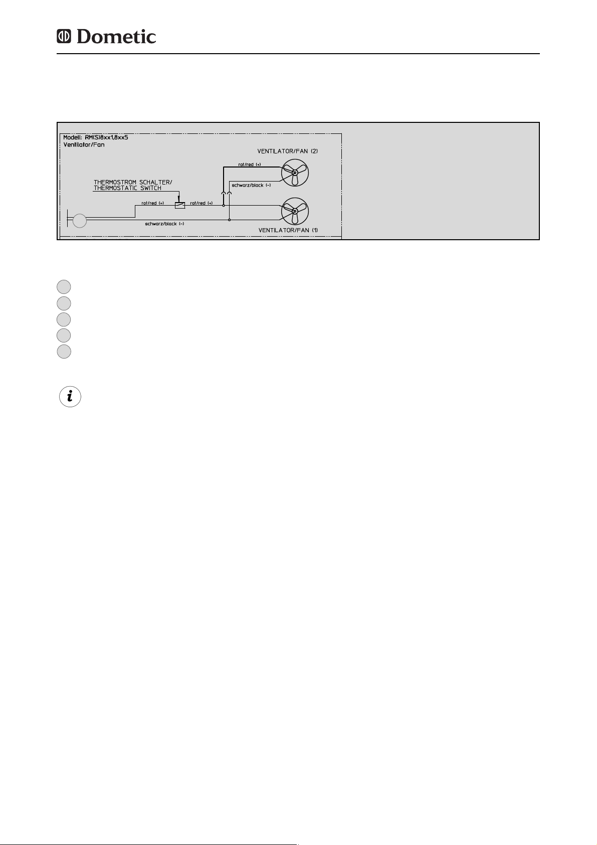
Ventilator (optional) RM(S) 8xx1, RM(S) 8xx5 :
Abb. 46
1
Zum Betrieb des Gerätes ist es unerlässlich,
eine 12V DC Dauerversorgung an den Klemmen C/D anzuschließen. (Dauerversorgung
für die Funktionselektronik)
= 12V OUT / 12V-Versorgung für optionale Anschlüsse
= Masse Heizelement 12V
= Plus Heizelement 12V
= Minus 12-Dauerversorgung Elektronik
= Plus 12-Dauerversorgung Elektronik
1
A
B
C
D
Page 28

28
www.dometic.com
Page 29
RM 8400 RM 8401 RM 8405 RM 8500 RM 8501 RM 8505 RM 8550 RM 8551 RM 8555
RMS 8400 RMS 8401 RMS 8405 RMS 8460 RMS 8461 RMS 8465 RMS 8500 RMS 8501
RMS 8505 RMS 8550 RMS 8551 RMS 8555 RML 8550 RML 8551 RML 8555 RMSL 8500
RMSL 8501 RMSL 8505
MBA 05/2012
N 1-1
Installation instructions
Absorption refrigerator for recreation vehicles
EN
English
Page 30
©
Dometic GmbH - 2011 - Subject to change without notice
0.0 Unpacking and Transport . . . . . . . . . . . . . . . . . . . . . . . . . . . . . . . . 3
1.0 General . . . . . . . . . . . . . . . . . . . . . . . . . . . . . . . . . . . . . . . . . . . . . . 4
1.1 Introduction . . . . . . . . . . . . . . . . . . . . . . . . . . . . . . . . . . . . . . . . . . . . . . . . . . . . . . . . . . . . . . . . 4
1.2 Guide to these operating instructions . . . . . . . . . . . . . . . . . . . . . . . . . . . . . . . . . . . . . . . . . . . .4
1.3 Copyright protection . . . . . . . . . . . . . . . . . . . . . . . . . . . . . . . . . . . . . . . . . . . . . . . . . . . . . . . . . 4
1.4 Explanation of symbols used in this manual . . . . . . . . . . . . . . . . . . . . . . . . . . . . . . . . . . . . . . . 4
1.5 Warranty . . . . . . . . . . . . . . . . . . . . . . . . . . . . . . . . . . . . . . . . . . . . . . . . . . . . . . . . . . . . . . . . . . . 5
1.6 Limitation of liability . . . . . . . . . . . . . . . . . . . . . . . . . . . . . . . . . . . . . . . . . . . . . . . . . . . . . . . . . . 5
1.7 Declaration of conformity . . . . . . . . . . . . . . . . . . . . . . . . . . . . . . . . . . . . . . . . . . . . . . . . . . . . . . 5
2.0 Safety instructions . . . . . . . . . . . . . . . . . . . . . . . . . . . . . . . . . . . . . . 6
2.1 Application according to regulations . . . . . . . . . . . . . . . . . . . . . . . . . . . . . . . . . . . . . . . . . . . . .6
2.2 User's responsibility . . . . . . . . . . . . . . . . . . . . . . . . . . . . . . . . . . . . . . . . . . . . . . . . . . . . . . . . . . 6
2.3 Working upon and checking the refrigerator . . . . . . . . . . . . . . . . . . . . . . . . . . . . . . . . . . . . . . . 6
2.4 Operating the refrigerator with gas . . . . . . . . . . . . . . . . . . . . . . . . . . . . . . . . . . . . . . . . . . . . . . 6
3.0 Description of model . . . . . . . . . . . . . . . . . . . . . . . . . . . . . . . . . . . . 7
3.1 Model identification . . . . . . . . . . . . . . . . . . . . . . . . . . . . . . . . . . . . . . . . . . . . . . . . . . . . . . . . . . 7
3.2 Refrigerator rating plate . . . . . . . . . . . . . . . . . . . . . . . . . . . . . . . . . . . . . . . . . . . . . . . . . . . . . . . 7
3.3 Technical data . . . . . . . . . . . . . . . . . . . . . . . . . . . . . . . . . . . . . . . . . . . . . . . . . . . . . . . . . . . . . . 7
4.0 Installation instructions . . . . . . . . . . . . . . . . . . . . . . . . . . . . . . . . . . 10
4.1 Installation . . . . . . . . . . . . . . . . . . . . . . . . . . . . . . . . . . . . . . . . . . . . . . . . . . . . . . . . . . . . . . . . . 10
4.1.1 Side installation . . . . . . . . . . . . . . . . . . . . . . . . . . . . . . . . . . . . . . . . . . . . . . . . . . . . . . . . . . . . . . . . . . . . . . 10
4.1.2 Side installation with floor-roof ventilation . . . . . . . . . . . . . . . . . . . . . . . . . . . . . . . . . . . . . . . . . . . . . . . . . 11
4.1.3 Rear installation . . . . . . . . . . . . . . . . . . . . . . . . . . . . . . . . . . . . . . . . . . . . . . . . . . . . . . . . . . . . . . . . . . . . . 11
4.1.4 Draught-proof installation . . . . . . . . . . . . . . . . . . . . . . . . . . . . . . . . . . . . . . . . . . . . . . . . . . . . . . . . . . . . . . 12
4.2 Ventilation and air extraction of the refrigerator . . . . . . . . . . . . . . . . . . . . . . . . . . . . . . . . . . . . 13
4.3 Installing the ventilation system . . . . . . . . . . . . . . . . . . . . . . . . . . . . . . . . . . . . . . . . . . . . . . . . . 14
4.4 Exhaust gas duct and installing the fume flue . . . . . . . . . . . . . . . . . . . . . . . . . . . . . . . . . . . . . . 15
4.5 Installation recess . . . . . . . . . . . . . . . . . . . . . . . . . . . . . . . . . . . . . . . . . . . . . . . . . . . . . . . . . . . . 16
4.5.1 Installation in the recess . . . . . . . . . . . . . . . . . . . . . . . . . . . . . . . . . . . . . . . . . . . . . . . . . . . . . . . . . . . . . . . 16
4.6 Securing the refrigerator . . . . . . . . . . . . . . . . . . . . . . . . . . . . . . . . . . . . . . . . . . . . . . . . . . . . . . 17
4.7 Inserting of the decor panel . . . . . . . . . . . . . . . . . . . . . . . . . . . . . . . . . . . . . . . . . . . . . . . . . . . . 17
4.8 Gas installation . . . . . . . . . . . . . . . . . . . . . . . . . . . . . . . . . . . . . . . . . . . . . . . . . . . . . . . . . . . . . . 19
4.9 Electrical installation . . . . . . . . . . . . . . . . . . . . . . . . . . . . . . . . . . . . . . . . . . . . . . . . . . . . . . . . . . 21
4.9.1 Mains connection . . . . . . . . . . . . . . . . . . . . . . . . . . . . . . . . . . . . . . . . . . . . . . . . . . . . . . . . . . . . . . . . . . . . 21
4.9.2 Battery connection . . . . . . . . . . . . . . . . . . . . . . . . . . . . . . . . . . . . . . . . . . . . . . . . . . . . . . . . . . . . . . . . . . . 21
4.9.3 Cable connections . . . . . . . . . . . . . . . . . . . . . . . . . . . . . . . . . . . . . . . . . . . . . . . . . . . . . . . . . . . . . . . . . . . 22
4.9.4 D+ and solar connection (only for AES models) . . . . . . . . . . . . . . . . . . . . . . . . . . . . . . . . . . . . . . . . . . . . 24
4.9.5 Wiring diagrams . . . . . . . . . . . . . . . . . . . . . . . . . . . . . . . . . . . . . . . . . . . . . . . . . . . . . . . . . . . . . . . . . . . . . 25
2
Table of contents
Dometic GmbH
In der Steinwiese 16
D-57074 Siegen
www.dometic.com
Page 31

3
Lifting / carrying the refrigerator
0.0 Unpacking and Transport
Never use parts on the refrigerator other than those shown in the illustration (particularly
not the cooling unit, gas lines and control panel) for carrying or lifting the refrigerator !
This prevents damage to the refrigerator.
CAUTION!
NOT
OK
OK
OK
Page 32

4
General
1.0 General
On installation of the appliance, the technical
and administrative regulations of the country
in which the vehicle will first be used must be
adhered to. Otherwise the refrigerator must be
installed as described in these instructions. In
Europe, for example, gas appliances, cable
routing, installation of gas cylinders, as well as
approval and checking for leaks must comply
with EN 1949 for liquid gas systems in vehi-
cles.
1.1 Introduction
Before you start installing the refrigerator,
please read the installation instructions
carefully.
These instructions provide you with the necessary guidance for the proper installation of
your refrigerator. Observe in particular the
safety instructions. Observation of the
instructions and handling recommendations is
important for dealing with the refrigerator
safely and for protecting you from injury and
the refrigerator from damage. You must understand what you have read before you carry out
a task.
Keep these instructions in a safe place
close to the refrigerator so they may be
referred to at any time.
1.2 Guide to these installation
instructions
The information, texts and illustrations in these
instructions are copyright protected and are
subject to industrial property rights.
No part of these instructions may be reproduced, copied or utilised in any other way without written authorisation by Dometic GmbH,
Siegen.
1.3 Copyright protection
1.4 Explanation of symbols
used in this manual
Warning notices are identified by symbols. A
supplementary text gives you an explanation
of the degree of danger.
Observe these warning notices rigorously.
You will thus protect yourself and other
people from injury, and the appliance from
damage.
Warning notices
DANGER indicates an imminent hazardous
situation which, if not avoided, could result in
death or serious injury.
DANGER!
WARNING indicates a potentially hazardous
situation which, if not avoided, could result in
death or serious injury
WARNING!
WARNING indicates a potentially hazardous
situation which, if not avoided, could result in
death or serious injury
CAUTION!
CAUTION (used without the safety alert sym-
bol) indicates a potentially hazardous situation
which, if not avoided, may result in damage to
the appliance.
CAUTION!
Page 33

5
General
All information and guidance in these operating instructions were prepared after taking
into consideration the applicable standards
and regulations as well as the current state of
the art. Dometic reserves the right to make
changes at any time which are deemed to be
in the interest of improving the product and
safety.
Dometic will assume no liability for damage in
the case of :
non-observation of the operating instructi-
ons
application not in accordance with the
regulations or provisions
use of non-original spare parts
modifications and interferences to the
appliance
effect of environmental influences, such as
- temperature fluctuations
- humidity
1.6 Limitation of liability
1.7 Declaration of conformity
Warranty arrangements are in accordance
with EC Directive 44/1999/CE and the normal
conditions applicable for the country concerned. For warranty or other maintenance, please contact our customer services department.
Any damage due to improper use is not covered by the warranty. The warranty does not
cover any modifications to the appliance or
the use of non-original Dometic parts. The
warranty does not apply if the installation and
operating instructions are not adhered to and
no liability shall be entertained.
1.5 Warranty
Information
INFORMATION gives you supplementary and
useful guidance when dealing with your refrigerator.
Environmental Tips
ENVIRONMENTAL TIPS gives you useful gui-
dance for saving energy and disposal of the
appliance.
Page 34

6
Safety instructions
2.0 Safety instructions
This refrigerator is designed for installation in
recreation vehicles such as caravans or
motorhomes. The appliance has been typeapproval tested for this application in accordance with the EC Gas Directive.
The refrigerator is to be used solely for storing
foodstuffs.
2.1 Application according to
regulations
2.3 Working upon and checking
the refrigerator
Work on gas equipment, exhaust system
and electrical facilities must be carried
out by authorised personnel only.
Substantial damage to property and/or
injury to persons can arise through unprofessional procedures.
WARNING!
Never use an unshielded flame to check
gas bearing parts and pipes for leakage!
There is a danger of fire or explosion.
DANGER!
Never open the absorber cooling unit! It is
under high pressure.
There is a danger of injury!
WARNING!
Anyone operating the refrigerator must be
familiar with the safe handling and understand
the advice in these operating instructions.
2.2 User's responsibility
It is imperative that the operating pressure
corresponds to the data specified on the
rating plate of the appliance. Compare the
operating pressure of the rating plate with the
data specified on the pressure reducing valve
of the liquid gas cylinder.
2.4 Operating the refrigerator
with gas
The refrigerator must not be exposed to
rain.
CAUTION!
Page 35

7
Description of model
Dometic refrigerators are equipped for a connection pressure of 30 mbar. For connection
to a 50 mbar gas system, use Truma VDR
50/30 medium pressure controller.
3.0 Description of model
3.1 Model identification
The rating plate is to be found on the inside of
the refrigerator. It contains all important details
of the refrigerator. You can read off from this
the model identification, the product number
and the serial number. You will need these
details whenever you contact the customer
service centre or when ordering spare parts.
3.2 Refrigerator rating plate
Model number
Product number
Serial number
Electrical rating details
Gas pressure
2
1
3
4
5
RM
8 4 0 0
1
5
(S)
(L)
Refrigerator Mobile /
Mobile Absorption Refrigerator
Model range
4 = Width 486mm
5 = Width 523mm
Depth:
0 = Standard
5 = + 55mm
6 = + 65mm
Stepped cabinet
„Large“
Example :
0
manual energy selection + manual ignition
(battery igniter)
1
manual energy selection, automatic ignition
(MES)
5
automatic and manual energy selection,
automatic ignition (AES)
Fig. 1
Example
2
1
3
4
5
Page 36

8
3.3 Technical data
Description of model
Fig. 3Fig. 2
RMS 8xxx
RM 8xxx
H
W
D
RML 8xxx
Fig. 4
Model Dimensions Gross capacity
Rating details
Consumption * Net Ignition
H x W x D (mm) with without mains/battery electricity/gas weight Piezo Automat
Depth incl. door freezer compartment over 24hrs
RMS 8400
RMS 8401
RMS 8405
RM 8400
RM 8401
RM 8405
RMS 8460
RMS 8461
RMS 8465
RMS 8500
RMS 8501
RMS 8505
RMS 8550
RMS 8551
RMS 8555
RM 8500
RM 8501
RM 8505
RM 8550
RM 8551
RM 8555
RML 8550
RML 8551
RML 8555
RMSL 8500
RMSL 8501
RMSL 8505
821x486x568
821x486x568
821x486x568
821x486x568
821x486x568
821x486x568
821x486x633
821x486x633
821x486x633
821x523x568
821x523x568
821x523x568
821x523x623
821x523x623
821x523x623
821x523x568
821x523x568
821x523x568
821x523x623
821x523x623
821x523x623
1245x523x625
1245x523x625
1245x523x625
1245x523x568
1245x523x568
1245x523x568
80 / 8 lit.
80 / 8 lit.
80 / 8 lit.
90 / 8 lit.
90 / 8 lit.
90 / 8 lit.
90 / 11 lit.
90 / 11 lit.
90 / 11 lit.
90 / 9 lit.
90 / 9 lit.
90 / 9 lit.
103 /12 lit.
103 /12 lit.
103 /12 lit.
100 / 9 lit.
100 / 9 lit.
100 / 9 lit.
115 /12 lit.
115 /12 lit.
115 /12 lit.
179 /33 lit.
179 /33 lit.
179 /33 lit.
145 /28 lit.
145 /28 lit.
145 /28 lit.
25 kg
25 kg
25 kg
27 kg
27 kg
27 kg
26 kg
26 kg
26 kg
26 kg
26 kg
26 kg
27 kg
27 kg
27 kg
28 kg
28 kg
28 kg
30 kg
30 kg
30 kg
45 kg
45 kg
45 kg
40 kg
40 kg
40 kg
85 lit.
85 lit.
85 lit.
95 lit.
95 lit.
95 lit.
96 lit.
96 lit.
96 lit.
96 lit.
96 lit.
96 lit.
110 lit.
110 lit.
110 lit.
106 lit.
106 lit.
106 lit.
122 lit.
122 lit.
122 lit.
189 lit.
189 lit.
189 lit.
155 lit.
155 lit.
155 lit.
125 W / 120 W
125 W / 120 W
125 W / 120 W
135 W / 130 W
135 W / 130 W
135 W / 130 W
125 W / 120 W
125 W / 120 W
125 W / 120 W
125 W / 120 W
125 W / 120 W
125 W / 120 W
125 W / 120 W
125 W / 120 W
125 W / 120 W
135 W / 130 W
135 W / 130 W
135 W / 130 W
135 W / 130 W
135 W / 130 W
135 W / 130 W
190 W / 170 W
190 W / 170 W
190 W / 170 W
190 W / 170 W
190 W / 170 W
190 W / 170 W
•
•
•
•
•
•
•
•
•
•
•
•
•
•
•
•
•
•
•
•
•
•
•
•
•
•
•
ca.2,5 KWh / 270 g
ca.2,5 KWh / 270 g
ca.2,5 KWh / 270 g
ca.2,4 KWh / 270 g
ca.2,4 KWh / 270 g
ca.2,4 KWh / 270 g
ca.2,5 KWh / 270 g
ca.2,5 KWh / 270 g
ca.2,5 KWh / 270 g
ca.2,5 KWh / 270 g
ca.2,5 KWh / 270 g
ca.2,5 KWh / 270 g
ca.2,6 KWh / 270 g
ca.2,6 KWh / 270 g
ca.2,6 KWh / 270 g
ca.2,4 KWh / 270 g
ca.2,4 KWh / 270 g
ca.2,4 KWh / 270 g
ca.2,6 KWh / 270 g
ca.2,6 KWh / 270 g
ca.2,6 KWh / 270 g
ca.3,2 KWh / 380 g
ca.3,2 KWh / 380 g
ca.3,2 KWh / 380 g
ca.3,2 KWh / 380 g
ca.3,2 KWh / 380 g
ca.3,2 KWh / 380 g
Curved door models
Page 37

9
Description of model
Subject to technical changes.
*Average consumption measured at an average ambient temperature of 25°C in pursuance of ISO Standard.
Model Dimensions Gross capacity
Rating details
Consumption * Net Ignition
H x W x D (mm) with without mains/battery electricity/gas weight Piezo Automat
Depth incl. door freezer compartment over 24hrs
RMS 8500
RMS 8501
RMS 8505
RMS 8550
RMS 8551
RMS 8555
RM 8500
RM 8501
RM 8505
RM 8550
RM 8551
RM 8555
821x523x541
821x523x541
821x523x541
821x523x596
821x523x596
821x523x569
821x523x541
821x523x541
821x523x541
821x523x596
821x523x596
821x523x596
86 / 9 lit.
86 / 9 lit.
86 / 9 lit.
99 /12 lit.
99 /12 lit.
99 /12 lit.
96 / 9 lit.
96 / 9 lit.
96 / 9 lit.
111 /12 lit.
111 /12 lit.
111 /12 lit.
26 kg
26 kg
26 kg
27 kg
27 kg
27 kg
28 kg
28 kg
28 kg
30 kg
30 kg
30 kg
92 lit.
92 lit.
92 lit.
106 lit.
106 lit.
106 lit.
102 lit.
102 lit.
102 lit.
118 lit.
118 lit.
118 lit.
125 W / 120 W
125 W / 120 W
125 W / 120 W
125 W / 120 W
125 W / 120 W
125 W / 120 W
135 W / 130 W
135 W / 130 W
135 W / 130 W
135 W / 130 W
135 W / 130 W
135 W / 130 W
•
•
•
•
•
•
•
•
•
•
•
•
ca.2,5 KWh / 270 g
ca.2,5 KWh / 270 g
ca.2,5 KWh / 270 g
ca.2,6 KWh / 270 g
ca.2,6 KWh / 270 g
ca.2,6 KWh / 270 g
ca.2,4 KWh / 270 g
ca.2,4 KWh / 270 g
ca.2,4 KWh / 270 g
ca.2,6 KWh / 270 g
ca.2,6 KWh / 270 g
ca.2,6 KWh / 270 g
Flat door models
Page 38

10
Installation
4.0 Installation instructions
The unit and the exhaust duct system must be
in principle installed so that it is accessible for
maintenance work, can be easily installed and
dismantled and removed from the vehicle without great effort.
Installation and connection of the appliance
must comply with the latest technical regulations, as follows:
The electrical installation must comply
with national and local regulations.
The gas installation must comply with
national and local regulations.
European Standard EN 1949
European Standards EN 60335-1,
EN 60335-2-24, EN 1648-1 , EN 1648-2
The appliance must be installed in such
a way that it is shielded from excessive
heat radiation.
Excessive heat impairs performance and raises the energy consumption of the refrigerator!
4.1 Installation
Deviations from these installation instructions without prior notification of Dometic
result in Dometic GmbH's warranty obligations becoming void!
The appliance may be installed by authorised personnel only!
WARNING!
(Fig. 6) The air vent grilles offer an unobstructed dissipation of heat and exhaust gas even
when the door is opened.
4.1.1 Side installation
If the appliance is installed on the same side of
the vehicle as the entrance door, it is desirable
that the door does not cover the refrigerator's
vents. (Fig. 5, Clearance door/ventilation grille
at least 25 mm). Otherwise ventilation could
be impaired which causes a loss in cooling
performance. Awnings are often placed at the
door side of a caravan. This complicates evacuation of combustion gases and heat through
the ventilation grilles (loss in cooling performance)!
(Fig.5) The air vent grilles are blocked. There
must be a distance between the door and the
air vents of at least 25 mm!
If the door/grille distance is between 25 mm
and 45 mm, we recommend installing a
Dometic ventilation kit (
item no. 241 2985 -
00/0
) to achieve an optimal cooling perfor-
mance in high ambient temperatures.
Fig. 5
Fig. 6
Air vent grille not-
blocked! OK!
Page 39

11
Installation
Fig. 7
floor opening:
at least 50 mm wide,
at least 520 mm long
hot air
condenser
Recommendation:
Roof vent
R500
Proper ventilation of the refrigerator can also
be achieved by lower air intake aperture in the
floor and upper roof exhaust vent (see Fig. 7).
A flue has to be provided between the top
edge of the refrigerator and the roof ventilation
which directs the hot air and the exhausts
straight to the air vent in the roof.
The floor opening must have a cross section of
at least 250 cm² . Protect the opening, e.g.
with a baffle plate and a net, to prevent dirt
from entering the gas burner. Compared to
side ventilation, this ventilation method can
allow more dirt to enter the rear area of the
refrigerator, which makes regular maintenance
of the gas burner, at least once a year, necessary.
With this installation method, regular maintenance of the gas burner is only possible
once the device has been dismantled. It is
imperative that the refrigerator be installed
in a way to allow easy removal.
We therefore recommend providing an adequate access opening (service flap) for
ready serviceability from the outside.
4.1.2 Side installation with floor-roof
ventilation
Another unfavourable method of rear installation is to install the air intake and exhaust grilles (Fig. 10) at the side wall of the recreation
vehicle. The air-heat recirculation is very
restricted which means that heat exchangers
(condenser, absorber) cannot be adequately
cooled. The optional method of an additional
air vent grille installed in the floor also exhibits
an insufficient air flow duct.
Fig. 8
Fig. 9
Air vent grille not
blocked ! OK!
Air vent grille
blocked !
4.1.3 Rear installation
Rear installation often causes an unfavourable
installation arrangement, as ideal ventilation
cannot always be assured (e.g. the lower ventilation grille is covered by the bumper or the
rear lights of the vehicle!) (Fig. 8). The maximum cooling performance of the aggregate is
actually not available.
Page 40

12
Fig. 10
The maximum cooling performance is not
available! Do not apply this installation
method, as it does not provide proper ventilation! Please refer to the description in
section 4.2 .
CAUTION!
4.1.4 Draught-proof installation
Refrigerators in motorhomes, caravans or
other vehicles must be installed in a draughtproof manner (EN 1949). This means that the
combustion air for the burner is not taken from
the living space and that exhaust fumes are
prevented from entering the living space.
Adequate sealing between the back of the
refrigerator and the vehicle interior has to be
provided.
Dometic strongly recommends carrying this
out using a flexible seal (in order to simplify
later removal and installation of the unit for
maintenance purposes.
By no means use durable sealing compounds, fitting foam or similar material to
realise draught-proof installation of the
refrigerator! Do NOT use any easily inflammable materials for sealing (in particular
silicon sealing compound or similar). Risk
of fire! The device manufacturer's product
liability and warranty shall lapse if such
materials are used.
WARNING!
The lip seals (1) are installed at the bottom and
on each side in the installation recess (Fig. 11-
13). A heat deflector plate (2) is installed in the
installation recess above the refrigerator. Affix
the this plate to the caravan wall, do NOT
attach to the refrigerator !
Attach the deflector plate so that the heated
air escapes through the top ventilation grill into
the open air and no heat build-up can be produced.
Fig. 12
Fig. 11
Fig. 13
1
1
2
2
Proposal 1
Installation
Page 41
13
The cavity in-between the outer vehicle wall
and refrigerator is completely isolated from the
vehicle interior. Intrusion of exhaust fumes into
the living space is prevented. Fumes will escape through the upper ventilation grille to the
outside.
The draught-proof installation does not require a special exhaust gas duct to be used. This
installation method allows the use of the same
air vent grille LS200 at the top and at the bottom without flue duct. .-Nummer :
If a flue duct is nevertheless desirable, incorporate the LS100 ventilation system with flue
duct into the upper air vent opening. (
For
installation, please refer to "4.4"
)
Deviations require the consent of the manufacturer!
In the event of high ambient temperatures,
full performance of the cooling unit can
only be achieved by means of adequate
ventilation and extraction.
A correct installation of the refrigerator is
essential for its correct operation, as due to
physical reasons heat builds up at the back of
the appliance which must be allowed to escape into the open air.
4.2 Ventilation and air extraction of the refrigerator
The refrigerator is later pushed into the installation recess from the front. Ensure that the
seals abut the case evenly.
This installation option facilitates the removal
and installation of the appliance for servicing.
Fig. 14
Fasten the sealing lips to a stop bar on the
rear side (1), e.g. by gluing.
1
Proposal 2
Installation
Ventilation is provided for the unit by means of
two apertures in the caravan wall. Fresh air
enters at the bottom, extracts the heat and
exits through the upper vent grille (chimney
effect).
The upper ventilation grille should be positioned as high as possible above the condenser (1, , Fig.16). Install the lower ventilation grille at floor level of the recess (Fig.
16,17), allowing unburnt gas (heavier than air)
to escape directly into the open air.
Fig. 15
Page 42

14
Correct mounting of the lower ventilation grille facilitates access to the connections and
functional parts during maintenance.
Fig. 18
Fig. 19
The LS 100 upper vent system kit consists of
the mounting frame (RS 1640), the air grille
including flue gas duct (AS 1620) and the winter cover (WA120). The LS 200 lower vent
system kit consists of the mounting frame (RS
1650), the air grille (AS1 630, but without flue
gas duct) and the winter cover (WA130).
4.3 Installing the ventilation system
LS 100
LS 200
1
2
3
4
Installation
Fig. 16
1
2
1
2
Ventilation grille LS 100 or LS 200
Ventilation grille LS 200
2
1
Should this arrangement prove impossible,
a ventilation aperture must be introduced
by the manufacturer of the vehicle into the
recess floor in order to avoid the accumulation of unburnt gas on the floor.
The ventilation grilles must have an open
cross-section of at least 250cm². This is
achieved by using the Dometic LS100/LS 200
absorber ventilation and air extraction system
which has been tested and approved for this
purpose.
Fig. 17
1
The gas burner must be located above the
edge (1, Fig. 17).
An installation other than described will
reduce the cooling capacity and jeopardise the manufacturer's warranty/product
liability.
CAUTION!
Page 43

15
Fig. 20
Fig. 24
Seal the mounting frame
making it waterproof
(
does not apply for
mounting frames with
integral seal
).
1
Fig. 21
Insert frame and screw
into position
2
To install the ventilation grilles, cut two rectangles (451 mm x 156 mm) in the outer wall of
the vehicle (
for position of the cuts, see point
4.2
).
Fig. 22
Insert and lock ventilation grille.
3
Fig. 23
Clip the insert for flue
gas duct in position (
only
for L100 upper ventilation system kit
).
4
Insert winter cover.
5
Installation
The exhaust gas duct system must be made in
such a manner as to achieve a complete
extraction of combustion products to the outside of living space. The duct system must
slope in an upward direction in order to avoid
a build-up of condensate. The type of exhaust
gas duct shown in Fig. 25 allows the installation of the winter cover next to (10) (Fig. 25).
4.4 Exhaust gas duct and installing the fume flue
Installing the standard fume flue
1. Connect T-piece (1) to adaptor (2) or flue
pipe (3) as required and affix with screw (4).
Ensure that heat baffle (5) is lodged in the correct position.
2. Insert flue pipe with cover plate (6) through
the appropriate aperture in the upper frame (7)
and connect to T-piece (1). If necessary, shorten flue pipe (6) to the required length.
3. Insert and lock ventilation grill LS 100 (8) in
the mounting frame (7).
4. Put cap (9) on flue pipe (6).
5. Insert extractor insert (10) into ventilation
grille (8) .
Fig. 25
1
2
3
4
5
6 79
10
8
min. 15mm
Page 44

16
Installation
Model Height H
ST
Depth T
ST
RMS 8400
RMS 8401
RMS 8405
RMS 8460
RMS 8461
RMS 8465
RMS 8500
RMS 8501
RMS 8505
RMS 8550
RMS 8551
RMS 8555
RMSL 8550
RMSL 8551
RMSL 8555
220 mm
220 mm
220 mm
220 mm
220 mm
220 mm
220 mm
220 mm
220 mm
220 mm
220 mm
220 mm
220 mm
220 mm
220 mm
235 mm
235 mm
235 mm
235 mm
235 mm
235 mm
235 mm
235 mm
235 mm
235 mm
235 mm
235 mm
235 mm
235 mm
235 mm
Push the appliance far enough into the recess
until the front edge of the refrigerator casing is
aligned with the front of the recess. Allow a
gap of 15-20 mm between the back wall of
the recess and the refrigeration unit.
Ensure that the refrigerator is installed
level in the recess.
The refrigerator must be installed draughtproof in a recess (also refer to Section "4.1.4").
The measurements of the recess are stated in
the table below. Step (1) (Fig. 26) is only required for cabinets with a step. The floor of the
recess must be level, allowing the appliance to
be pushed easily into its correct position. The
floor must be substantial enough to bear the
weight of the appliance.
4.5 Installation recess
Fig. 26
T
ST
min
15-20mm
H
ST
1
4.5.1 Installation in the recess
Page 45

17
After the refrigerator is put in its final place,
secure the screws into the wall of the recess.
The screws must penetrate the casing of the
refrigerator.
Fig. 27
Fig. 28
In the sidewalls of the refrigerator, there are
four plastic sleeves for securing the refrigerator. The sidewalls or strips attached for securing the refrigerator must be prepared to hold
the screws firmly in place even when under
increased load (while the vehicle is moving).
Fastening screws and caps are supplied with
the refrigerator
4.6 Securing the refrigerator
Always insert screws through the sleeves
provided as otherwise components laid in
foam, such as cables etc., could be damaged.
CAUTION!
4.7 Inserting the decor panel
Remove the lateral ledge (1) the door
(ledge is attached, not screwed).
Shift decor panel (2) away from the door
and insert the new decor panel. Re-attach
ledge (1).
Fig. 29
Model RM 8xxx, RMS 8xxx
Decor panel dimensions :
743 +/- 0.5 mm 472 +/- 0.5 mm max. 2.2 mm
Casing width
486 mm
Height Width Thickness
743 +/- 0.5 mm 510.5 +/- 0.5 mm max. 2.2 mm
Casing width
523 mm
Height Width Thickness
2
1
Installation
Page 46

18
Installation
Fig. 31
Fig. 32
Decor panel dimensions RML 8xxx :
1169,5 +0/-1 mm 507,5 +0/-1 mm max. 1.7 mm
Casing width
523 mm
Height Width Thickness
CAUTION!
Fig. 30
1
2
1.
2.
3.
4.
Model RM 8xxx, RMS 84xx
Fig. 35
Fig. 36
Fig. 34
Model RMx(L) 8xxx, frameless decor
panel
1
2
3
4
1.
2.
Fig. 33
Page 47

19
Installation
Observe the regulations stated in secti-
on 2.1 .
This refrigerator is provided for installati
on within liquid gas equipment in compliance with EN1949 and must be run
exclusively on liquid gas (propane, butane) (no natural gas, town gas).
A fixed, pre-set pressure regulator com-
plying with EN 12864 must be connected
to the liquid gas cylinder.
The pressure regulator must concur with
the operating pressure specified on the
rating plate of the appliance. The operating pressure corresponds to the standard pressure of the country of specification (EN 1949, EN 732).
Only one connection pressure is permis
sible for any one vehicle! A plate showing the permanent, clearly legible notice must be displayed in full view at the
point where the gas cylinder is installed.
The gas connection to the appliance
must be installed securely and free of
stress using pipe connectors and must
be securely connected to the vehicle (a
hose connection is not permissible) (EN
1949).
The gas connection to the appliance is
effected by means of (Ermeto-) olive
type fitting L8, DIN 2353-ST, complying
with EN 1949 ( s. figure 37, 38).
After professional installation, a leakage
test as well as a flame test have to be
carried out by qualified personnel* in
* Specialised personnel are accredited experts who are
able, by virtue of their training and knowledge, to vouch
for the correct installation and implementation of the leakage test.
conformity with EN 1949. A test certificate has to be issued.
The refrigerator must be equipped with a
shut-off valve allowing to cut the supply
line. Such a shut-off device must be
readily accessible to the user.
4.8 Gas installation
The gas connection shall be carried out
by specialised personnel* only.
WARNING!
Dometic refrigerators are equipped for a connection pressure of 30 mbar. For connection
to a 50 mbar gas system, use Truma VDR
50/30 medium pressure controller.
When using LPG gas, please consider that the
burner needs cleaning at shorter intervals due
to the gas combustion method (2 - 3 times per
year recommended).
Connection pressure and gas categories
The refrigerators are operated using the gases
and inlet pressures stated below. The pressure reducing valves between the gas cylinder
and refrigerator to be used must comply with
the categories stated in the following table.
Category Pressure in mbar GAS
I3B / P(30) 30 Butane
30 Propane
I3+ (28-30/37) 28-30 Butane
37 Propane
Page 48

20
Installation
Fig. 38
SW 14
SW 17
CAUTION!
20 Nm
max
10 Nm
max
Gas connection
RM(S) 8xx1, RM(S) 8xx5 models
Fig. 37
Gas connection RM(S) 8xx0 models
SW 14
SW 17
(Ermeto-) Olive type fitting L8,
(EN ISO 8434)
1
1
1
Page 49

21
Fig. 42
The electrical installation must be in
accordance with the national regulations
of the respective countries.
The connection cables must be routed in
a way to prevent contact with hot
components of the unit/burner or with
sharp edges.
Changes to the internal electrical instal-
lation or the connection of other electrical components (e.g. external fan) to the
internal wiring of the appliance will render the e1/ CE admittance as well as any
claims from warranty and product liability void!
* Specialised personnel are accredited experts who are
able, by virtue of their training and knowledge, to vouch
for the correct installation.
4.9 Electrical installation
Die elektrische Installation darf nur von
einer autorisierten Fachkraft* ausgeführt
werden.
WARNING!
4.9.1 Mains connection
The power should be supplied by a pro-
perly grounded socket outlet or a grounded non-detachable connection. Where
a socket outlet with mains supply is
used, the outlet must be freely accessible.
Should the connection cable be dama
ged, have it replaced by Dometic
Customer Services or by qualified per
sonnel to avoid hazards.
We recommend leading the power supply via
a board-side fuse protection.
Cable cross sections and cable lengths :
Motorcaravan & Caravan (inside)
4 mm² (RML 8xxx = 6 mm²)< 6 m
6 mm² (RML 8xxx = 10 mm²)> 6 m
Caravan (outside)
min 2,5 mm²(EN1648-1)
2,5mm²
Installation
4.9.2 Battery connection
The machine's 12V connection cable is connected (observing correct polarity) to a terminal strip (RMx 8xx0) or plug-in-contacts (RMx
8xx1, 8xx5). The wiring for the 12V heating
element (refer to A, B wiring diagram connections) must be direct and by the shortest possible route to the battery or electric generator.
Provide a 20 A fuse to protect on-board 12V
circuit.
In order to ensure that the 12V power supply is
shut off when stopping the engine (otherwise
the battery would discharge within a few
hours), perform the power supply to the 12V
heating element (connection A/B in wiring diagram) in a way to have the 12V supply only live
while the vehicle ignition is switched on.
The connection C/D (interior light, electronics)
must be permanently provided by a 12V DC
power supply to be protected by a 2A fuse.
If the appliance is installed in a caravan
the respective leads for the 12V+ and 12Vconnections A/B and C/D must not be
connected to each other on the caravanside (EN 1648-1).
CAUTION!
Page 50

22
Fig. 41
4.9.3 Cable connections
Position of the control electronics :
The power supplies for electronics and heating element are connected directly at the
plug-in contacts of the electronics.
For MES and AES it is compulsory to provide a permanent 12V DC supply at the terminals C/D (permanent voltage supply for
functional electronics).
Stepped cabinet models
Fig. 42
Standard models
Connections for models RM(S) 8xx0
Connections for models RM(S) 8xxx (MES),
RM(S) 8xx5 (AES) :
Fig. 39
A = Ground heating element DC (brown)
B = Positive connection, heating element
DC (brown)
C = Ground interior lighting (black)
D = Positive connection lighting (white)
Fig. 40
2
2
L = brown
N = blue
Earth= yellow/green
1
1
A
B
C
D
-
+
-
+
Mains connection
12V connection
on the vehicle
on the appliance
Installation
Page 51

23
Fig. 43
Contacts at the electronics:
Earth
Mains connection (230 V AC)
INput heating element
(12 V DC)
Electronics connection (12 V)
D+ signal connection
S+ signal connection
Heating element mains
connection (230 V AC)
2
3
4
1
Plug-in contacts (manufacturer: Stocko®)
MF 9562-002-80E
MF 9562-002-8 OC
3-pin with D+ contact:
MF 9562-003-8 30 960-000-00
2-pin :
MF 9562-002-8 ON + spade connector 6.3 x 0.8
MKH 5132-1-0-200
2
1
3
4
Installation
2
1
3
-
+
D+/S+
OUTput heating
element (12 V DC)
Page 52

24
Installation
4.9.4 D+ and solar connection (only
for AES models)
D+ signal connection
In >Automatic Mode< the AES electronic
system automatically selects the most efficient
energy supply. In automatic mode the electronic system uses the D+ signal (dynamo +) of
the alternator to detect 12V DC. 12V DC operation is selected only while the engine is running in order to prevent battery discharge.
S+ signal connection:
12V DC energy can be optionally achieved by
mounting solar equipment to the vehicle. The
solar power equipment must be provided with
a solar charging controller with AES output
(adequate charging controllers available in
selected stores). The "S+ connection (Solar +)
must be connected to the respective terminal
of the solar charging controller (AES output).
The electronic system uses the S+ signal of
the solar charging controller to detect solar
12V DC.
Cable cross-sectional areas:
There are no particularly high current flows via
the D+ and S+ connection; therefore no particularly large cross-section is required for these
connections (approx. 1mm² is sufficient).
Page 53

25
Installation
Fig. 44
Circuit diagram RM(S) 8xx0 :
4.9.5 Circuit diagrams
A
B
C
D
Page 54

26
Circuit diagram RM(S) 8xx1, RM(S) 8xx5 :
Installation
Fig. 45
1
C
D B
A
Page 55

27
Fan (optional) RM(S) 8xx1, RM(S) 8xx5 :
Fig. 46
1
For MES and AES it is compulsory to provide
a permanent 12V DC supply at the terminals
C/D (permanent voltage supply for functional
electronics
= 12V OUT / 12 V power supply for optional connections
= Ground connection heating element 12VDC
= Positive connection, heating element 12VDC
= Ground connection electronics 12VDC
= Positive connection electonics 12VDC
1
A
B
C
D
Page 56

28
www.dometic.com
Page 57

RM 8400 RM 8401 RM 8405 RM 8500 RM 8501 RM 8505 RM 8550 RM 8551 RM 8555
RMS 8400 RMS 8401 RMS 8405 RMS 8460 RMS 8461 RMS 8465 RMS 8500 RMS 8501
RMS 8505 RMS 8550 RMS 8551 RMS 8555 RML 8550 RML 8551 RML 8555 RMSL 8500
RMSL 8501 RMSL 8505
MBA 05/2012
N 1-1
Instrucciones de instalación
Frigorífico de absorción para vehículos de ocio
ES
Español
Page 58

©
Dometic GmbH - 2011 - Reservado el derecho de realizar modificaciones
0.0 Desembalaje y transporte . . . . . . . . . . . . . . . . . . . . . . . . . . . . . . . . 3
1.0 Aspectos generales . . . . . . . . . . . . . . . . . . . . . . . . . . . . . . . . . . . . . 4
1.1 Introducción . . . . . . . . . . . . . . . . . . . . . . . . . . . . . . . . . . . . . . . . . . . . . . . . . . . . . . . . . . . . . . . . 4
1.2 Indicaciones sobre las presentes instrucciones de instalación . . . . . . . . . . . . . . . . . . . . . . . . . 4
1.3 Derechos de autor . . . . . . . . . . . . . . . . . . . . . . . . . . . . . . . . . . . . . . . . . . . . . . . . . . . . . . . . . . . 4
1.4 Explicación de los símbolos utilizados . . . . . . . . . . . . . . . . . . . . . . . . . . . . . . . . . . . . . . . . . . . 4
1.5 Garantía . . . . . . . . . . . . . . . . . . . . . . . . . . . . . . . . . . . . . . . . . . . . . . . . . . . . . . . . . . . . . . . . . . . 5
1.6 Limitación de responsabilidad . . . . . . . . . . . . . . . . . . . . . . . . . . . . . . . . . . . . . . . . . . . . . . . . . . 5
1.7 Declaración de conformidad . . . . . . . . . . . . . . . . . . . . . . . . . . . . . . . . . . . . . . . . . . . . . . . . . . . 5
2.0 Indicaciones de seguridad . . . . . . . . . . . . . . . . . . . . . . . . . . . . . . . 6
2.1 Uso conforme a lo prescrito . . . . . . . . . . . . . . . . . . . . . . . . . . . . . . . . . . . . . . . . . . . . . . . . . . . 6
2.2 Responsabilidad del usuario . . . . . . . . . . . . . . . . . . . . . . . . . . . . . . . . . . . . . . . . . . . . . . . . . . . 6
2.3 Trabajos y comprobaciones en el frigorífico . . . . . . . . . . . . . . . . . . . . . . . . . . . . . . . . . . . . . . . 6
2.4 Funcionamiento del frigorífico con gas . . . . . . . . . . . . . . . . . . . . . . . . . . . . . . . . . . . . . . . . . . . 6
3.0 Descripción del modelo . . . . . . . . . . . . . . . . . . . . . . . . . . . . . . . . . . 7
3.1 Denominación de modelo . . . . . . . . . . . . . . . . . . . . . . . . . . . . . . . . . . . . . . . . . . . . . . . . . . . . . 7
3.2 Placa de características del frigorífico . . . . . . . . . . . . . . . . . . . . . . . . . . . . . . . . . . . . . . . . . . . . 7
3.3 Datos técnicos . . . . . . . . . . . . . . . . . . . . . . . . . . . . . . . . . . . . . . . . . . . . . . . . . . . . . . . . . . . . . . 8
4.0 Instrucciones de montaje . . . . . . . . . . . . . . . . . . . . . . . . . . . . . . . . 10
4.1 Montaje . . . . . . . . . . . . . . . . . . . . . . . . . . . . . . . . . . . . . . . . . . . . . . . . . . . . . . . . . . . . . . . . . . . 10
4.1.1 Montaje lateral . . . . . . . . . . . . . . . . . . . . . . . . . . . . . . . . . . . . . . . . . . . . . . . . . . . . . . . . . . . . . . . . . . . . . . 10
4.1.2 Montaje lateral con ventilación de suelo/techo . . . . . . . . . . . . . . . . . . . . . . . . . . . . . . . . . . . . . . . . . . . . . 11
4.1.3 Montaje en la parte trasera . . . . . . . . . . . . . . . . . . . . . . . . . . . . . . . . . . . . . . . . . . . . . . . . . . . . . . . . . . . . 11
4.1.4 Instalación sin corriente de aire . . . . . . . . . . . . . . . . . . . . . . . . . . . . . . . . . . . . . . . . . . . . . . . . . . . . . . . . . 12
4.2 Ventilación del frigorífico . . . . . . . . . . . . . . . . . . . . . . . . . . . . . . . . . . . . . . . . . . . . . . . . . . . . . . 13
4.3 Instalación del sistema de ventilación . . . . . . . . . . . . . . . . . . . . . . . . . . . . . . . . . . . . . . . . . . . .14
4.4 Conducto de extracción y colocación de la chimenea de extracción . . . . . . . . . . . . . . . . . . . 15
4.5 Hueco para montaje . . . . . . . . . . . . . . . . . . . . . . . . . . . . . . . . . . . . . . . . . . . . . . . . . . . . . . . . . . 16
4.5.1 Inserción en el hueco . . . . . . . . . . . . . . . . . . . . . . . . . . . . . . . . . . . . . . . . . . . . . . . . . . . . . . . . . . . . . . . . . 16
4.6 Fijación del frigorífico . . . . . . . . . . . . . . . . . . . . . . . . . . . . . . . . . . . . . . . . . . . . . . . . . . . . . . . . . 17
4.7 Colocación de la placa de decoración . . . . . . . . . . . . . . . . . . . . . . . . . . . . . . . . . . . . . . . . . . . 17
4.8 Instalación de gas . . . . . . . . . . . . . . . . . . . . . . . . . . . . . . . . . . . . . . . . . . . . . . . . . . . . . . . . . . . 19
4.9 Instalación eléctrica . . . . . . . . . . . . . . . . . . . . . . . . . . . . . . . . . . . . . . . . . . . . . . . . . . . . . . . . . . 21
4.9.1 Conexión de red . . . . . . . . . . . . . . . . . . . . . . . . . . . . . . . . . . . . . . . . . . . . . . . . . . . . . . . . . . . . . . . . . . . . . 21
4.9.2 Conexión a la batería . . . . . . . . . . . . . . . . . . . . . . . . . . . . . . . . . . . . . . . . . . . . . . . . . . . . . . . . . . . . . . . . . 21
4.9.3 Conexiones de cables . . . . . . . . . . . . . . . . . . . . . . . . . . . . . . . . . . . . . . . . . . . . . . . . . . . . . . . . . . . . . . . . 22
4.9.4 Conexión D+ y conexión solar (sólo en modelos AES) . . . . . . . . . . . . . . . . . . . . . . . . . . . . . . . . . . . . . . . 24
4.9.5 Esquemas de conexiones . . . . . . . . . . . . . . . . . . . . . . . . . . . . . . . . . . . . . . . . . . . . . . . . . . . . . . . . . . . . . 25
2
Índice
Dometic GmbH
In der Steinwiese 16
D-57074 Siegen
www.dometic.com
Page 59

3
Elevamiento / Transporte del frigorífico
0.0 Desembalaje y transporte
Para llevar o elevar el frigorífico nunca utilice otras piezas del mismo que las indicadas en
la ilustración (en especial, no utilice el grupo frigorífico, los conductos de gas ni el panel
de mandos).
Evitará que el frigorífico resulte dañado.
PRECAUCIÓN!
NO
SI
SI
Page 60

4
Al montar el aparato, deberán cumplirse las
prescripciones técnicas y administrativas del
país en el que se matricula el vehículo por primera vez. Además también deberán seguirse
las prescripciones de montaje del fabricante.
Por ejemplo, en Europa, los aparatos de gas,
la colocación de líneas, la colocación de bombonas de gas, así como el control y examen
de estanqueidad deben cumplir la norma EN
1949 para instalaciones de gas líquido.
Los datos, textos e ilustraciones de las
instrucciones están protegidos por derechos
de autor, y están sujetos a los derechos de
protección de propiedad industrial.
Queda prohibido reproducir, fotocopiar o utilizar de algún modo cualquier parte de estas
instrucciones sin la autorización escrita de
Dometic GmbH, con sede en Siegen.
1.3 Derechos de autor
Antes de instalar el frigorífico, lea minuciosamente las presentes instrucciones de
instalación.
Estas instrucciones contienen las indicaciones
necesarias para instalar su frigorífico correctamente. Tenga especialmente en cuenta las
indicaciones de seguridad. Es importante
atenerse a las indicaciones y los modos de
proceder descritos: evitará que usted y el frigorífico sufran daños. Antes de aplicar una
medida deberá haber entendido las instrucciones.
Guarde el presente manual de instalación
en un lugar seguro, para poder volver a
consultarlo en cualquier momento.
1.2 Indicaciones sobre las presentes instrucciones
1.4 Explicación de los símbolos
utilizados
Las advertencias vienen señaladas mediante
iconos. Un texto complementario le detalla el
grado de peligro existente.
Tenga en cuenta este tipo de advertencias.
Al hacerlo, se protegerá, protegerá a otras
personas y evitará que el aparato sufra
daños.
Advertencias
PELIGRO indica una situación de peligro inme-
diato que puede provocar la muerte o heridas
graves en caso de no aplicar las medidas indicadas.
PELIGRO!
ADVERTENCIA indica una posible situación de
peligro que puede provocar la muerte o heridas
graves en caso de no aplicar las medidas indicadas.
ADVERTENCIA!
PRECAUCIÓN indica una posible situación de
peligro que puede provocar heridas leves o
medias en caso de no aplicar las medidas indicadas.
PRECAUCIÓN!
PRECAUCIÓN sin el símbolo de seguridad indi-
ca una posible situación de peligro que puede
provocar daños en el aparato en caso de no
aplicar las medidas indicadas.
PRECAUCIÓN!
1.0 Aspectos generales
Aspectos generales
1.0 Aspectos generales
1.1 Introducción
Aspectos generales
Page 61

5
Toda la información y las indicaciones contenidas en las presentes instrucciones de uso
han sido redactadas teniendo en cuenta las
normas y prescripciones vigentes, así como el
estado de la técnica. Dometic se reserva el
derecho de poder realizar en todo momento
modificaciones de producto que mejoren el
producto y su seguridad.Dometic üno asume
ninguna responsabilidad en caso de:
No seguir las instrucciones de uso
Utilizar el aparato de forma no acorde a la
prescrita
Utilizar piezas de repuesto no originales
Realizar modificaciones o intervenciones
en el aparato
Influencias de entorno, como por ejemplo
- cambios de temperatura
- humedad del aire
1.6 Limitación de responsabilidad
1.7 Declaración de conformidad
Información
INFORMACIÓN le proporciona datos comple-
mentarios prácticos para utilizar su frigorífico.
Indicación medioambiental
INDICACIÓN MEDIOAMBIENTAL le propor-
ciona consejos para ahorrar energía y desechar el aparato.
Las tramitaciones de garantía siguen la directiva CE 44/1999/CE y las condiciones prescritas en el país de venta. Para cuestiones relacionadas con la garantía o asistencia técnica,
diríjase a nuestro servicio de atención al cliente. Las averías debidas a un uso indebido del
aparato no se incluirán dentro de la garantía.
Toda modificación del aparato o toda utilización de piezas de repuesto que no sean piezas
Dometic originales , así como el no atenerse
a las instrucciones de montaje y uso, provocará la exoneración de la garantía y la exclusión
de los derechos de hacer efectiva una responsabilidad.
1.5 Garantía
Aspectos generalesAspectos generales
Page 62
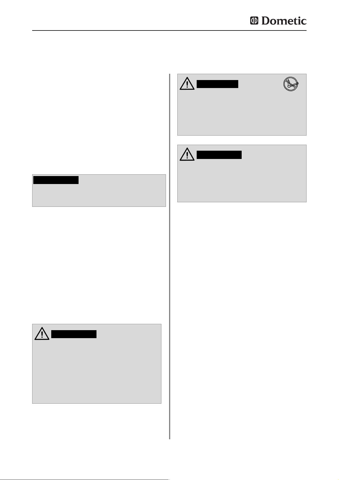
6
Indicaciones de seguridad
2.0 Indicaciones de seguridad
Este frigorífico ha sido concebido para ser
instalado en vehículos de ocio, como por
ejemplo en caravanas o autocaravanas. El
aparato cumple la directiva comunitaria sobre
aparatos de gas de la UE según el modelo de
construcción.
Utilice el frigorífico exclusivamente para refrigerar y almacenar alimentos.
2.1 Uso conforme a lo prescrito
2.3 Trabajos y comprobaciones
en el frigorífico
Los trabajos relacionados con las áreas
del gas, de la extracción de humos y los
componentes eléctricos tan sólo podrán
ser realizados por el servicio técnico
autorizado. Si se aplican medidas no
apropiadas pueden provocarse daños
materiales o personales considerables.
ADVERTENCIA!
Nunca compruebe la hermeticidad del
aparato en las piezas y los conductos de
gas teniendo una llama ardiendo.
Existe el peligro de producirse un incendio o una explosión..
PELIGRO!
Nunca abra el grupo frigorífico de absorción. Está sometido a una gran presión.
Existe el peligro de resultar herido.
ADVERTENCIA!
Las personas que manejan el frigorífico deberán saber cómo utilizarlo de forma segura y
conocer las indicaciones de estas instrucciones de uso.
2.2 Responsabilidad del usuario
La presión de funcionamiento deberá corresponderse obligatoriamente con los datos
registrados en la placa de características del
frigorífico. Compare los datos de la presión de
trabajo de la placa del modelo con los del indicador de presión en el cilindro de gas líquido.
2.4 Funcionamiento del
frigorífico a gas
El refrigerador no debe ser expuesto a la
lluvia.
PRECAUCION!
Page 63
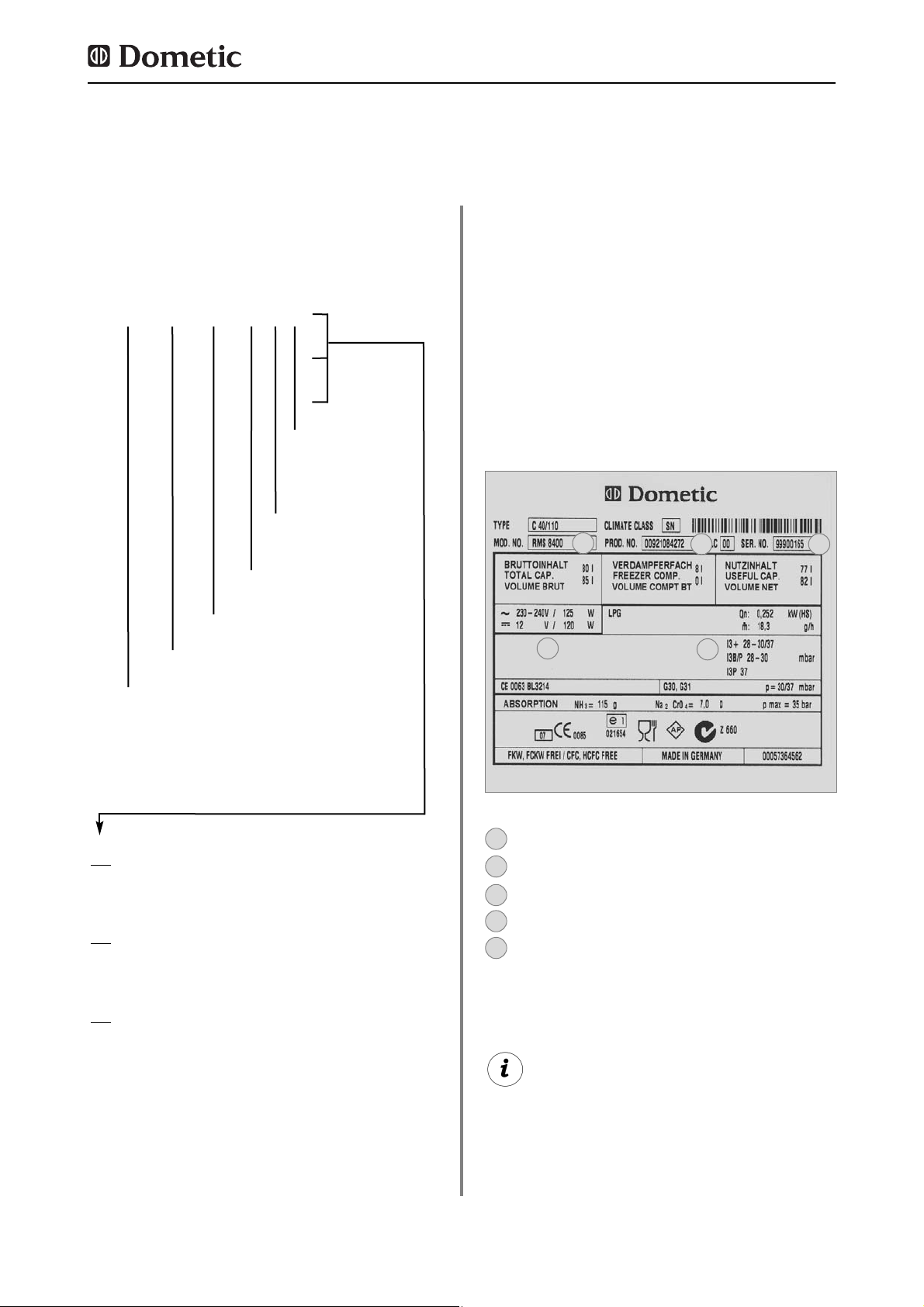
7
Todos los frigoríficos Dometic de esta serie
están equipados para una presión de conexión de 30 mbar. Al conectarlos a una instalaci-
ón de 50 mbar utilice el regulador de presión
de admisión Truma VDR 50/30.
Ejemplo
N° de modelo
N° de producto
Número de serie
Valores de conexión eléctrica
Presión de gas
2
2
1
1
3
3
4
4
5
5
RM
8 4 0 0
1
5
(S)
(L)
Refrigerator Mobile / Frigorífico de
absorción portátil
0
selección manual de energía + encendido
manual (ignicion de pila)
1
selección manual de energía, encendido
automático (MES)
5
selección automática y manual de energía,
encendido automático (AES)
Serie de modelo
4 = ancho 486mm
5 = ancho 523mm
Fondo :
0 = estándar
5 = + 55mm
6 = + 65mm
Modelo con paso de rueda
„Large“
Ejemplo:
Descripción del modelo
3.0 Descripción del modelo
3.1 Denominación de modelo
En el interior del frigorífico encontrará la placa
de características del frigorífico. En ella se
encuentran todos los datos importantes del
aparato. Podrá leer la denominación de modelo, el número de producto y el número de
serie. Necesitará estos datos a la hora de contactar con el Servicio de atención al cliente o
a la hora de pedir piezas de repuesto.
3.2 Placa de características del
frigorífico
Page 64

8
3.3 Datos técnicos
Descripción del modelo
Fig. 3Fig. 2
RMS 8xxx
RM 8xxx
H
B
T
RML 8xxx
Fig. 4
Modelo Dimensiones Capacidad total
Valores
Consumo * Peso Encendido
Al x An x F (mm) con sin
de conexión
Eléctrico/Gas neto Piezo autom.
Fdo. incl. puerta congelador congelador Red/Batería en 24h
RMS 8400
RMS 8401
RMS 8405
RM 8400
RM 8401
RM 8405
RMS 8460
RMS 8461
RMS 8465
RMS 8500
RMS 8501
RMS 8505
RMS 8550
RMS 8551
RMS 8555
RM 8500
RM 8501
RM 8505
RM 8550
RM 8551
RM 8555
RML 8550
RML 8551
RML 8555
RMSL 8500
RMSL 8501
RMSL 8505
821x486x568
821x486x568
821x486x568
821x486x568
821x486x568
821x486x568
821x486x633
821x486x633
821x486x633
821x523x568
821x523x568
821x523x568
821x523x623
821x523x623
821x523x623
821x523x568
821x523x568
821x523x568
821x523x623
821x523x623
821x523x623
1245x523x625
1245x523x625
1245x523x625
1245x523x568
1245x523x568
1245x523x568
80 / 8 lit.
80 / 8 lit.
80 / 8 lit.
90 / 8 lit.
90 / 8 lit.
90 / 8 lit.
90 / 11 lit.
90 / 11 lit.
90 / 11 lit.
90 / 9 lit.
90 / 9 lit.
90 / 9 lit.
103 /12 lit.
103 /12 lit.
103 /12 lit.
100 / 9 lit.
100 / 9 lit.
100 / 9 lit.
115 /12 lit.
115 /12 lit.
115 /12 lit.
179 /33 lit.
179 /33 lit.
179 /33 lit.
145 /28 lit.
145 /28 lit.
145 /28 lit.
25 kg
25 kg
25 kg
27 kg
27 kg
27 kg
26 kg
26 kg
26 kg
26 kg
26 kg
26 kg
27 kg
27 kg
27 kg
28 kg
28 kg
28 kg
30 kg
30 kg
30 kg
45 kg
45 kg
45 kg
40 kg
40 kg
40 kg
85 lit.
85 lit.
85 lit.
95 lit.
95 lit.
95 lit.
96 lit.
96 lit.
96 lit.
96 lit.
96 lit.
96 lit.
110 lit.
110 lit.
110 lit.
106 lit.
106 lit.
106 lit.
122 lit.
122 lit.
122 lit.
189 lit.
189 lit.
189 lit.
155 lit.
155 lit.
155 lit.
125 W / 120 W
125 W / 120 W
125 W / 120 W
135 W / 130 W
135 W / 130 W
135 W / 130 W
125 W / 120 W
125 W / 120 W
125 W / 120 W
125 W / 120 W
125 W / 120 W
125 W / 120 W
125 W / 120 W
125 W / 120 W
125 W / 120 W
135 W / 130 W
135 W / 130 W
135 W / 130 W
135 W / 130 W
135 W / 130 W
135 W / 130 W
190 W / 170 W
190 W / 170 W
190 W / 170 W
190 W / 170 W
190 W / 170 W
190 W / 170 W
•
•
•
•
•
•
•
•
•
•
•
•
•
•
•
•
•
•
•
•
•
•
•
•
•
•
•
ca.2,5 KWh / 270 g
ca.2,5 KWh / 270 g
ca.2,5 KWh / 270 g
ca.2,4 KWh / 270 g
ca.2,4 KWh / 270 g
ca.2,4 KWh / 270 g
ca.2,5 KWh / 270 g
ca.2,5 KWh / 270 g
ca.2,5 KWh / 270 g
ca.2,5 KWh / 270 g
ca.2,5 KWh / 270 g
ca.2,5 KWh / 270 g
ca.2,6 KWh / 270 g
ca.2,6 KWh / 270 g
ca.2,6 KWh / 270 g
ca.2,4 KWh / 270 g
ca.2,4 KWh / 270 g
ca.2,4 KWh / 270 g
ca.2,6 KWh / 270 g
ca.2,6 KWh / 270 g
ca.2,6 KWh / 270 g
ca.3,2 KWh / 380 g
ca.3,2 KWh / 380 g
ca.3,2 KWh / 380 g
ca.3,2 KWh / 380 g
ca.3,2 KWh / 380 g
ca.3,2 KWh / 380 g
Modellos con puerta curvada
Page 65

9
Modellbeschreibung
Reservado el derecho de realizar modificaciones técnicas.
*Consumo medio medido a una temperatura ambiental media de 25°C según en estándar ISO.
Modelo Dimensiones Capacidad total
Valores
Consumo * Peso Encendido
Al x An x F (mm) con sin
de conexión
Eléctrico/Gas neto Piezo autom.
Fdo. incl. puerta congelador congelador Red/Batería en 24h
RMS 8500
RMS 8501
RMS 8505
RMS 8550
RMS 8551
RMS 8555
RM 8500
RM 8501
RM 8505
RM 8550
RM 8551
RM 8555
821x523x541
821x523x541
821x523x541
821x523x596
821x523x596
821x523x569
821x523x541
821x523x541
821x523x541
821x523x596
821x523x596
821x523x596
86 / 9 lit.
86 / 9 lit.
86 / 9 lit.
99 /12 lit.
99 /12 lit.
99 /12 lit.
96 / 9 lit.
96 / 9 lit.
96 / 9 lit.
111 /12 lit.
111 /12 lit.
111 /12 lit.
26 kg
26 kg
26 kg
27 kg
27 kg
27 kg
28 kg
28 kg
28 kg
30 kg
30 kg
30 kg
92 lit.
92 lit.
92 lit.
106 lit.
106 lit.
106 lit.
102 lit.
102 lit.
102 lit.
118 lit.
118 lit.
118 lit.
125 W / 120 W
125 W / 120 W
125 W / 120 W
125 W / 120 W
125 W / 120 W
125 W / 120 W
135 W / 130 W
135 W / 130 W
135 W / 130 W
135 W / 130 W
135 W / 130 W
135 W / 130 W
•
•
•
•
•
•
•
•
•
•
•
•
ca.2,5 KWh / 270 g
ca.2,5 KWh / 270 g
ca.2,5 KWh / 270 g
ca.2,6 KWh / 270 g
ca.2,6 KWh / 270 g
ca.2,6 KWh / 270 g
ca.2,4 KWh / 270 g
ca.2,4 KWh / 270 g
ca.2,4 KWh / 270 g
ca.2,6 KWh / 270 g
ca.2,6 KWh / 270 g
ca.2,6 KWh / 270 g
Modellos con puerta plana
Page 66

10
4.0 Instrucciones de montaje
El aparato y el conducto de extracción deberán ser montados de forma que queden accesibles para realizar trabajos de servicio, y que
puedan montarse y desmontarse del vehículo
sin tener que realizar grandes esfuerzos.
A la hora de colocar y conectar el aparato
deberán seguirse las disposiciones :
La instalación eléctrica debe realizarse
aplicando las normas nacionales y locales.
La instalación de gas debe realizarse
aplicando las normas nacionales y locales.
Norma europea EN 1949
Normas europeas EN 60335-1,
EN 60335-2-24, EN 1648-1 , EN 1648-2
Instale el aparato de modo que quede
protegido contra una exposición excesiva al calor.
La exposición excesiva al calor perjudicará el
rendimiento y aumentará el consumo de
energía del frigoríficos.
4.1 Montaje
Ignorar la presente guía de montaje sin la
autorización previa de Dometic provocará
la anulación de la garantía por parte de
nuestra empresa.
La instalación del aparato sólo podrán
realizarla especialistas autorizados para
ello.
ADVERTENCIA!
Las rejillas de ventilación permiten que el calor
del grupo frigorífico y los gases salgan sin problemas incluso teniendo abierta la puerta del
frigorífico (Fig. 6).
4.1.1 Montaje lateral
Si el aparato se monta en el lateral de la puerta de acceso, deberá asegurarse de que la
rejilla de ventilación no quede tapada por la
puerta abierta (Fig. 5, Distancia puerta - rejilla
de ventilación mín. 25 mm). En caso contrario,
la ventilación será insuficiente, lo que mermará el rendimiento de la refrigeración. A menudo, el lado de la puerta del vehículo está dotado de un avancé. Éste dificulta el escape de
gases de combustión y de calor por la rejilla
de ventilación (merma de rendimiento de refrigeración).
Las rejillas de ventilación están obstruidas. La
distancia entre la puerta y la rejilla de ventilación debe ser al menos de 25 mm (Fig.5) .
Para distancias entre puerta/rejilla de entre 25
y 45 mm recomendamos que se instale el kit
de ventilación de Dometic (
n° de art. 241
2985 - 00/0
) , para conseguir un rendimiento
óptimo de refrigeración a altas temperaturas
ambientales.
Fig. 5
Fig. 6
¡Rejilla de ventilación libre! ¡Correcto!
Montaje
Page 67

11
Fig. 7
Abertura del suelo:
min. 50 mm de
ancho
min. 520 mm de largo
Aire caliente
Condensator
Recomendación:
conducto de
aire de techo
R500
Otra posibilidad es ventilar el frigorífico dejando una ranura de ventilación en el suelo e
instalando un sistema de ventilación en el
techo del vehículo (véase Fig. 7). Entre el
canto superior del frigorífico y la ventilación de
techo debe instalarse una chimenea que deje
salir el aire caliente y los gases de escape del
grupo frigorífico directamente por el sistema
de ventilación del techo.
La abertura del suelo debe tener una sección
transversal libre de al menos 250 cm². Esta
abertura debe tener una protección, por ejemplo, una chapa de desviación y una red, para
evitar que entre suciedad en la zona de combustión de gas. Con este tipo de ventilación
puede entrar más suciedad en la zona posterior del frigorífico (en comparación con la ventilación lateral), por lo que deberá realizarse un
mantenimiento regular del quemador de gas,
al menos una vez al año.
En esta variante de montaje, sólo se podrá
realizar el mantenimiento regular de la unidad del quemador de gas desmontando el
aparato. El frigorífico deberá instalarse
obligatoriamente de forma que quede
garantizado un fácil desmontaje.
Por tanto, recomendamos prever una abertura de mantenimiento (tapa de servicio) en
la parte exterior.
4.1.2 Montaje lateral con ventilación
de suelo/techo
Una variante poco propicia del montaje en la
parte trasera es la colocación lateral de la rejilla de ventilación (
Fig. 10
). La circulación del
aire caliente es muy limitada, lo que provoca
que los intercambiadores de calor (condensadores, absorbedores) ya no se refrigeran lo
suficiente. También la variante con una rejilla
de ventilación montada adicionalmente en el
suelo presenta una mala conducción de la
corriente de aire.
Fig. 8
Fig. 9
¡Rejilla de ventilación
libre! ¡Correcto!
¡Rejilla de ventilación
no libre!
4.1.3 Montaje en la parte trasera
A menudo, el montaje en la parte trasera provoca una situación de montaje poco propicia,
ya que no siempre queda garantizada una
ventilación óptima (p. ej., ¡la rejilla de ventilación inferior queda cubierta por el parachoques
o las luces traseras del vehículo!) (
Fig. 8
). El
máximo rendimiento de refrigeración del
grupo frigorífico no está disponible de forma
efectiva.
Montaje
Page 68

12
Fig. 10
¡No se dispone del máximo rendimiento
de refrigeración! No utilice esta opción de
montaje, ya que en esta variante la ventilación no queda garantizada tal y como se
describe en el punto 4.2.
PRECAUCION!
4.1.4 Instalación sin corriente de aire
Los aparatos frigoríficos en caravanas, autocaravanas u otros vehículos deben montarse
sin corriente de aire (EN 1949). Esto significa
que el aire necesario para la combustión del
quemador de gas no se absorbe del espacio
habitado, y que se evita que los gases entren
directamente al mismo.
Deberá preverse una obturación apropiada
entre el dorso del frigorífico y el habitáculo del
vehículo.
Dometic recomienda encarecidamente utilizar
un obturador flexible para así facilitar un desmontaje y montaje del aparato con fines de
mantenimiento.
En ningún caso deberá instalarse el frigorífico sin corriente de aire utilizando
pastas obturadoras resistentes o espumas (por ejemplo, espumas de montaje), u
otros productos similares. NO utilice
materiales fácilmente inflamables (sobre
todo pastas de sellado de silicona o similares) para la obturación. Podría provocar
un incendio. Al utilizarlos, se eximen la
garantía y la responsabilidad civil de producto del fabricante.
ADVERTENCIA!
Los retenes labiales (1) se colocan en el hueco
para montaje inferior y en los laterales pertinentes (Fig. 11-13). Una chapa de disipación
de calor (2) se coloca en el hueco para montaje situado encima del frigorífico (NO fijar al
frigorífico).
Coloque la chapa de disipación de modo que
el aire calentado pueda salir al exterior por la
rejilla de ventilación y no pueda producirse
ninguna acumulación térmica.
Fig. 12
Fig. 11
Fig. 13
1
1
2
2
Propuesta 1
Montaje
Page 69

13
El espacio que se encuentra entre la pared
exterior del vehículo y el frigorífico está estanqueizado de la zona habitada. Por tanto, los
gases no pueden entrar en la zona habitada.
Los gases salen por la rejilla superior de la
ventilación hacia el exterior. En la instalación
sin corriente de aire no es necesario utilizar un
conducto de extracción especial.
Con esta variante, puede utilizarse la misma
rejilla de ventilación LS200 sin conducto de
extracción tanto arriba como abajo.tic-Dicht-
Kit Si no obstante se desea tener una chime-
nea de extracción, monte el sistema de ventilación LS100 con conducto de extracción
(
Montaje de chimenea de extracción, véase
"4.4"
).
Las modificaciones deberán ser autorizadas por el fabricante.
A altas temperaturas ambientales, un rendimiento pleno del grupo frigorífico sólo
quedará garantizado mediante una ventilación suficiente.
El montaje correcto del aparato es importante
para el funcionamiento, ya que en la parte trasera del aparato se genera calor (por las condiciones físicas) que debe conducirse hacia el
exterior.
4.2 Ventilación del frigorífico
Más adelante, el frigorífico se insertará desde
arriba en el hueco para montaje. Asegúrese de
que las obturaciones están colocadas homogéneamente en la carcasa.
Así, el frigorífico podrá desmontarse fácilmente para realizar trabajos de mantenimiento y
reparaciones.
Fig. 14
Fije las faldas obturadoras en un listón tope
de la parte trasera (1), por ejemplo, pegándolas.
1
Propuesta 2
El grupo frigorífico se ventila mediante dos
aberturas de la pared de la caravana. El aire
fresco entra por abajo y circula saliendo calentado por la rejilla de ventilación superior (efecto chimenea).
La rejilla de ventilación superior debe colocarse lo más arriba posible sobre el condensador (1, Fig. 16) . La rejilla de ventilación inferior deberá colocarse a ras del
suelo del vehículo (Fig. 16,17) para que en
caso de que se escape el gas aún no quemado (más pesado que el aire), salga directamente al exterior.
Montaje
Fig. 15
Page 70

Una instalación divergente mermará el
rendimiento de refrigeración, además de
eximir la garantía/responsabilidad de producto.
PRECAUCION!
14
La colocación correcta de la rejilla de ventilación inferior facilita el acceso a las conexiones
del aparato y a las piezas funcionales a la hora
de realizar trabajos de mantenimiento.
Fig. 16
1
2
1
2
rejilla de ventilación LS 100 o LS 200
rejilla de ventilación LS 200
2
1
Fig. 18
Fig. 19
El sistema de ventilación superior LS 100 está
compuesto por un bastidor de montaje (RS
1640) (1), una rejilla de ventilación incl. conducto de extracción (AS 1620) (2, 3) y una cubierta
de invierno (WA120) (4). El sistema de ventilación inferior LS 200 también está compuesto por
un bastidor de montaje (RS 1650), rejilla de ventilación (AS 1630, no obstante sin conducto de
extracción) y una cubierta de invierno (WA130).
4.3 Instalación del sistema de
ventilación
LS 100
LS 200
1
2
3
4
Montaje
Si esto no es posible, el fabricante del vehículo deberá hacer un orificio de ventilación
en el fondo del hueco para que en caso de
que se escape el gas no quemado no se
acumule en el fondo.
Las rejillas de ventilación deben tener una
sección transversal libre de al menos
250cm². Ésta se consigue con el sistema de
ventilación con absorbedor LS 100 / LS 200
de Dometic, certificado y autorizado para este
propósito.
Fig. 17
1
El quemador de gas debe encontrarse
encima del canto (1, Fig. 17) befinden.
Page 71

15
Fig. 20
Fig. 24
Obturar el bastidor de
montaje de forma que
quede estanco (n
o es
necesario en los bastidores de montaje con
obturación integrada
).
1
Fig. 21
Colocar el bastidor y
atornillarlo fijamente.
2
Para proceder a instalar las rejillas de ventilación, corte un rectángulo (451 mm x 156 mm)
en la pared exterior del vehículo (para situar
los cortes, véase
"4.2"
).
Fig. 22
Colocar y bloquear las
rejillas de ventilación en
el bastidor de montaje.
3
Fig. 23
Encastrar la pieza para
el conducto de extracción (s
ólo en el sistema de
ventilación superior
LS100
).
4
Colocar la cubierta de invierno.
5
El conducto de extracción debe garantizar
que la desviación de los productos de combustión se produzca fuera del espacio habitado.
El conducto de extracción debe colocarse
siempre verticalmente para evitar que se acumulen condensados. En el tipo de conducto
de extracción mostrado en la fig 25 la cubierta de invierno (10, Fig. 25) puede colocarse
lateralmente.
4.4 Conducto de extracción y
colocación de la chimenea
de extracción
Colocación de la chimenea de extracción
estándar
1. Insertar la pieza en forma de T (1) en el
adaptador (2), o bien en el conducto de
extracción (3) y fijarla con el tornillo (4).
Deberá tener en cuenta que el distribuidor de
calor (5) se encuentra en su posición prevista.
2. Insertar el conducto de extracción completo con la placa cobertora (6) por la abertura prevista para ello del marco superior (7) y
conectarlo con la pieza en forma de T (1). En
caso pertinente, acortar el conducto de
extracción (6) a la longitud apropiada.
3. Colocar la rejilla de ventilación LS 100 (8)
en el bastidor de montaje (7) y bloquearlo con
el cierre de muletilla, que se encuentra en el
lado izquierdo de la rejilla.
4. Colocar la tapadera abatible (9) sobre el
conducto de extracción (6).
5. Colocar la pieza para el conducto de
extracción (10) en la rejilla de ventilación (8).
Montaje
Fig. 25
1
2
3
4
5
6 79
10
8
min. 15mm
Page 72

16
4.5.1 Inserción en el hueco
El aparato deberá insertarse en el hueco
hasta que el canto delantero de la carcasa del
frigorífico y el canto delantero del hueco estén
alineados. Entre la pared del fondo del hueco
y el grupo frigorífico deberá existir un espacio
libre de 15-20 mm.
l frigorífico deberá montarse en posición
vertical en el hueco.
El frigorífico deberá ser montado en un hueco
sin corriente de aire (v. tb. "4.1.4"). El nivel (1)
(Fig. 26) wsólo se necesita en los modelos con
paso de rueda. El suelo del hueco deberá ser
plano, de modo que el aparato pueda desplazarse sin dificultades a su posición correcta. El
suelo deberá ser lo suficientemente firme para
poder soportar el peso del aparato.
4.5 Hueco para montaje
Montaje
Fig. 26
T
ST
min
15-20mm
H
ST
1
Modello Altura H
ST
Fondo T
ST
RMS 8400
RMS 8401
RMS 8405
RMS 8460
RMS 8461
RMS 8465
RMS 8500
RMS 8501
RMS 8505
RMS 8550
RMS 8551
RMS 8555
RMSL 8550
RMSL 8551
RMSL 8555
220 mm
220 mm
220 mm
220 mm
220 mm
220 mm
220 mm
220 mm
220 mm
220 mm
220 mm
220 mm
220 mm
220 mm
220 mm
235 mm
235 mm
235 mm
235 mm
235 mm
235 mm
235 mm
235 mm
235 mm
235 mm
235 mm
235 mm
235 mm
235 mm
235 mm
Page 73

17
Una vez que el frigorífico se haya colocado en
su posición definitiva, los tornillos deberán
atornillarse por el frigorífico hasta la pared del
hueco.
Fig. 27
Fig. 28
En los laterales del frigorífico, existen cuatro
manguitos para fijar el frigorífico. Los laterales
o los listones colocados para fijar el frigorífico
deberán colocarse de modo que los tornillos
estén bien apretados incluso en los casos de
mayor esfuerzo (durante la marcha). Los tornillos de fijación y las tapaderas abatibles se
adjuntan con el frigorífico.
4.6 Fijación del frigorífico
Girar los tornillos siempre mediante los
casquillos previstos para ello, ya que en
caso contrario las piezas cubiertas de plástico, como por ejemplo los conductos,
podrían resultar dañadas.
PRECAUCION!
4.7 Colocación de la placa de
decoración
Retire el listón (1) lateral de la puerta (el
listón está encajado, no atornillado).
Desplace la placa de decoración (2) sacán
do la de la puerta, coloque la nueva placa
de decoración y vuelva a colocar el listón
(1) .
Fig. 29
Modello RM 8xxx, RMS 84xx
Dimensiones de la placa de decoración :
743 +/- 0.5 mm 472 +/- 0.5 mm max. 2.2 mm
Ancho de car
casa 486 mm
Altura Ancho Grosor
743 +/- 0.5 mm 510.5 +/- 0.5 mm max. 2.2 mm
Ancho de car
casa 523 mm
Altura Ancho Grosor
2
1
Montaje
Page 74
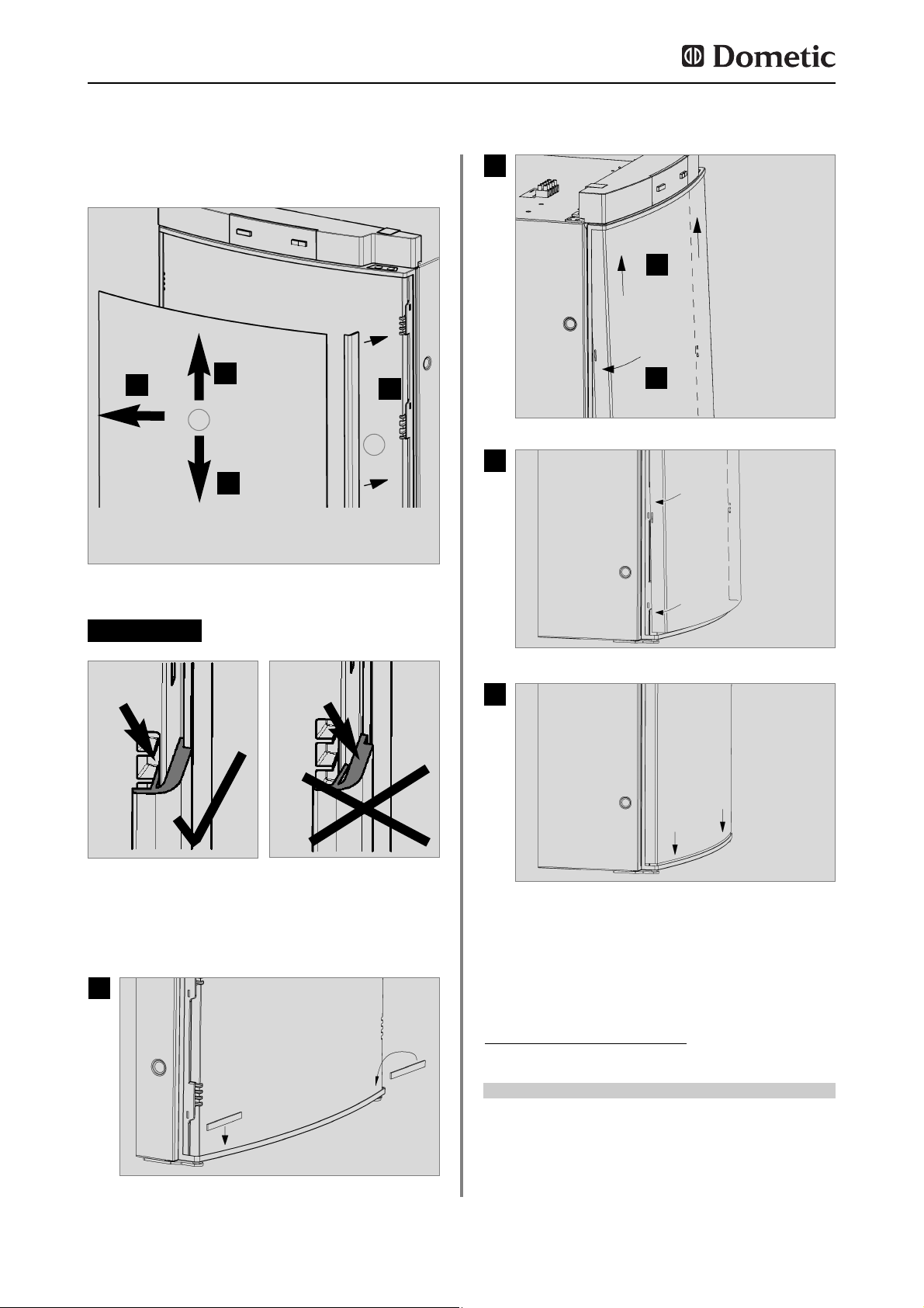
18
Montaje
Fig. 31
Fig. 32
Modello RM 8xxx, RMS 84xx
Dimensiones de la placa de decoración :
1169,5 +0/-1 mm 507,5 +0/-1 mm max. 1.7 mm
Ancho de car
casa
523 mm
Altura Ancho Grosor
PRECAUCION!
Fig. 33
Fig. 35
Fig. 36
Fig. 34
Modello RMx(L) 8xxx, placa de decoración
sin marco
1
2
3
4
Fig. 30
1
2
1.
1.
2.
2.
3.
4.
Page 75

19
Montaje
Siga las indicaciones listadas en el
punto 4.1.
Este frigorífico ha sido concebido para-
ser conectado a una instalación de gas
líquido según la norma EN1949, y funcionará únicamente con gas líquido (propano, butano) (NO con gas natural ni gas
ciudad).
Deberá instalarse un regulador ajustado
de forma fija según la norma EN 12864.
El regulador deberá concordar con la
presión de funcionamiento indicada en
la placa de características. La presión de
funcionamiento se corresponde con la
presión normativa del país pertinente
(EN 1949, EN732).
Únicamente se acepta una presión de
conexión por cada vehículo. Allí donde
se instale la bombona de gas, deberá
colocarse una placa claramente legible
que indique esta circunstancia.
La conexión de gas al aparato deberá
llevar una instalación altamente segura y
sin tensión, y deberá estar bien conecta
da al vehículo (no se permiten conexiones de goma) (EN 1949).
La conexión de gas con el aparato se
efectúa mediante un atornillado de anillo cortante ("Ermeto") K8, DIN 2353-ST
según EN 1949 (fig. 37,38).
La instalación conforme a las reglas del
arte deberá ser realizada por un espe
cialista autorizado*, que deberá realizar
una prueba de fugas y comprobar la
* Los especialistas autorizados son expertos reconoci
dos, que debido a su formación o a sus conocimientos
pueden garantizar que la instalación y el examen de
estan queidad ha sido realizado correctamente.
llama según la norma EN 1949. Al realizar dicha inspección se expedirá un certificado acreditativo.
El frigorífico deberá estar equipado con
un mecanismo de cierre instalado en el
conducto de abastecimiento. El meca nismo de cierre deberá ser instalado en
un lugar fácilmente accesible para el
usuario.
4.8 Instalación de gas
La toma de gas sólo podrá ser instalada
por un especialista autorizado*.
ADVERTENCIA!
Todos los frigoríficos Dometic de esta serie
están equipados para una presión de conexión de 30 mbar. Al conectarlos a una instalaci-
ón de 50 mbar utilice el regulador de presión
de admisión Truma VDR 50/30.
En caso de utilizar autogás deberá tener en
cuenta de que debido al tipo de combustión
del gas, el quemador deberá limpiarse más a
menudo (se recomienda hacerlo 2 a 3 veces al
año).
Presión de conexión y categorías de gas
Los frigoríficos funcionan con las presiones de
entrada y los gases citados a continuación.
Los reductores de presión que deben instalarse entre la bombona de gas y el frigorífico
deberán ser de una de las categorías indicadas en las siguientes tablas.
Categoría Presión en mbar GAS
I3B / P(30) 30 Butano
30 Propano
I3+ (28-30/37) 28-30 Butano
37 Propano
Page 76

20
Montaje
Fig. 38
SW 14
SW 17
PRECAUCION!
20 Nm
max
10 Nm
max
Conexión de gas en los modelos
RM(S)(L) 8xx1, RM(S)(L) 8xx5
Fig. 37
Conexión de gas en los modelos
RM(S)(L) 8xx0
SW 14
SW 17
Atornillado de anillo cortante ("Ermeto")
K8, DIN 2353-ST (EN ISO 8434)
1
1
1
Page 77
21
La instalación eléctrica debe realizarse
aplicando las normas nacionales.
El cable de conexión deberá colocarse
de modo que no puedan entrar en con
tacto con los componentes calientes del
grupo frigorífico / quemador o con can
tos afilados.
Al realizar modificaciones en la instalaci-
ón eléctrica o la conexión de otros componentes eléctricos (p. ej., un ventilador
adicional) al cableado interno del apara
to, provocará la exoneración de la aprobación e1/CE, así como todas los derechos de garantía y responsabilidad de
producto.
* Los especialistas autorizados son expertos reconoci
dos, que debido a su formación o a sus conocimientos
pueden garantizar que la instalación ha sido realizado
correctamente.
4.9 Instalación eléctrica
La instalación eléctrica sólo podrá ser
ejecutada por un especialista autorizado.*
ADVERTENCIA!
4.9.1 Conexión de red
La corriente eléctrica deberá sumini-
strarse de una caja de enchufe con puesta a tierra que cumpla las prescripcio
nes o a una conexión de red con puesta
a tierra. Si se utiliza el conducto de con
exión a red con enchufe, el enchufe
deberá estar siempre accesible.
Si el conducto de conexión resulta dañado, deberá ser sustituido por el servicio
posventa de Dometic o por un personal
cualificado para ello, para así evitar
posibles peligros.
Recomendamos que la línea de alimentación
lleve un fusible de a bordo..
Montaje
Fig. 42
4.9.2 Conexión a la batería
El cable de conexión de a bordo de 12 V se
conecta a una regleta de bornes del frigorífico
(RMx 8xx0) o en las tomas de corriente del
sistema electrónico (RMx 8xx1, 8xx5) con la
polaridad correcta. La conexión de los cables
del cartucho calentador (véase el cuadro de
conexiones A, B, cable de conexión rojo/blanco) deberá efectuarse mediante una conexión
directa y lo más corta posible con la batería o
el dínamo.
Las secciones transversales y longitudes :
Autocaravana y caravana (interior)
4 mm² (RML = 6 mm²)< 6 m
6 mm² (RML = 10 mm²)> 6 m
Caravana (exterior)
min 2,5 mm²(EN1648-1)
2,5mm²
A bordo del vehículo, el circuito de 12 V
deberá protegerse mediante un fusible de
20 A.
Para que al parar el motor del vehículo no olvide desconectar el modo de 12 V (la batería se
descargaría en unas pocas horas), recomendamos que el suministro de corriente para el
cartucho calentador (conexión A/B de los
esquemas de conexiones ) se realice de forma
que éste se interrumpa al girar la llave de
encendido. En la conexión C/D (iluminación,
sistema electrónico; cable de conexión
negro/violeta) deberá colocar una fuente de
alimentación continua de 12V (CC), que deberá llevar un fusible de 2A en el lateral.
Al realizar la instalación en la caravana los
conductos negativo y positivo correspondientes de las conexiones de 12 V A/B y
C/D no deberán ser conectados entre sí
(EN 1648-1).
PRECAUCION!
Page 78

22
4.9.3 Conexiones de cables
La conexión del abastecimiento de tensión
para el sistema electrónico y los elementos
calefactores se realiza directamente en las
tomas de corriente del sistema electrónico.
Para el funcionamiento de los tipos de aparatos MES y AES estará prohibido conectar
un abastecimiento continuo de 12 V a los
bornes C/D (abastecimiento continuo para
la electrónica funcional).
Conexiones en los modelos RM(S) 8xx0 :
Conexiones en los modelos RM(S) 8xxx
(MES), RM(S) 8xx5 (AES) :
Fig. 39
A = Masa elemento calentador CC
(marrón)
B = Positivo elemento calentador CC
(marrón)
C = Masa iluminación CC (negro)
D = Positivo iluminación 12 V CC (blanco)
Fig. 40
2
2
L = marrón
N = azul
Puesta a tierra = amarillo/verde
1
1
A
B
C
D
-
+
-
+
Conexión de red
Conexión a la batería (12V)
por parte del
vehículo
por parte
del aparato
Montaje
Fig. 41
Posición del control electrónico:
Modelos con paso de rueda
Fig. 42
Modelos estándar
Page 79

23
Fig. 43
Contactos en el sistema electrónico :
Puesta a tierra
Conexión de red (230V~)
ENTRADA de elemento
calefactor (12V-)
SALIDA de elemento
calefactor (12V-)
Conexión del sistema electrónico (12V)
Conexión de señal D+
Conexión de señal S+
Elemeno calefactor de red
(230V~)
2
3
4
1
Tomas de corriente (Fabricante Stocko®)
MF 9562-002-80E
MF 9562-002-8 OC
tripolar con toma D+:
MF 9562-003-8 30 960-000-00
bipolar:
MF 9562-002-8 ON + clavija plana 6.3 x 0.8
MKH 5132-1-0-200
2
1
3
4
Montaje
2
1
3
-
+
D+/S+
Page 80

24
Montaje
4.9.4 Conexión D+ y conexión solar
(sólo en modelos AES)
Conexión de señal D+:
En el modo automático ("Automatic mode")
el sistema electrónico AES selecciona el
modo de energía más adecuado automáticamente. En el modo automático, el sistema
electrónico utiliza la señal D+ (dínamo +) del
dínamo para reconocer el modo 12 V CC. El
funcionamiento con el modo de energía de 12
V CC sólo se seleccionará cuando el motor
esté en marcha para así evitar que la batería
se descargue.
Conexión de señal S+:
Como alternativa, el modo de funcionamiento
de 12 V CC puede ser alimentado mediante
un sistema de energía solar del vehículo. El
sistema de energía solar deberá estar equipado con regulador solar con salida AES (este
tipo de reguladores pueden adquirirse en
establecimientos especializados). La conexión
S+ (Solar +) deberá estar conectada al borne
correspondiente del regulador solar (salida
AES). El sistema electrónico emplea la señal
S+ del regulador solar para reconocer el 12 V
CC solar.
Secciones transversales de cables:
Por las conexiones D+ y S+ no fluye una corriente alta, por lo que no hace falta utilizar
cables de secciones transversales especialmente grandes (aprox. 1 mm² es suficiente).
Page 81
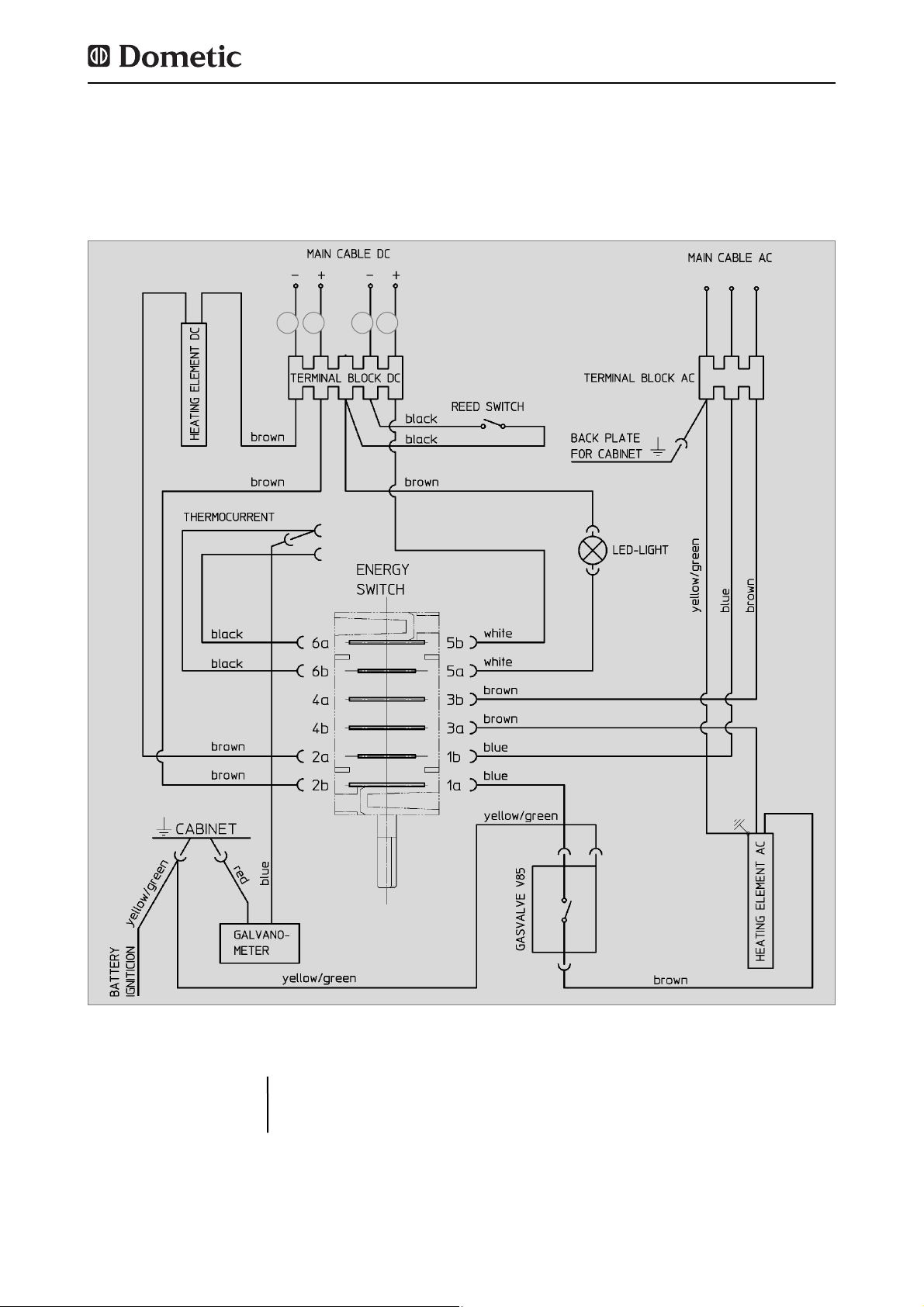
25
Montaje
Fig. 44
Esquema de conexiones RM(S) 8xx0 :
4.9.5 Esquemas de conexiones
A = ground heating element 12VDC
B = plus heating element 12VDC
C = ground interior light 12VDC
D = plus interior light 12VDC
A = Negativo elemento calentador 12 V CC
B = Positivo elemento calentador 12 V CC
C = Negativo iluminación 12 V CC
D = Positivo iluminación 12 V CC
Conexiones
A
B
C
D
Page 82

26
Esquema de conexiones RM(S) 8xx1, RM(S) 8xx5 :
Montaje
Fig. 45
1
C
D B
A
Page 83

27
Ventilador (opcional) RM(S) 8xx1, RM(S) 8xx5 :
Fig. 46
1
Para el funcionamiento de los tipos de aparatos MES y AES estará prohibido conectar
un abastecimiento continuo de 12 V a los
bornes C/D (abastecimiento continuo para la
electrónica funcional).
= 12V OUT / Abastecimiento 12V para conexiones opcionales
= Negativo elemento calentador 12 V CC
= Positivo elemento calentador 12 V CC
= Negativo electrónica 12 V CC
= Positivo electrónica 12 V CC
1
A
B
C
D
Leyenda
Connecting cable DC
Mains cable AC
Terminal block
GROUND
Heating element DC
Heating element AC
Frame heater
Reed-switch
Thermal switch
Temperature sensor
Electronic
Burner control device GFA
Gas valve GV 100
Gas burner
violet
red
white / red
brown
black
white
yellow/green
blue
Cable de conexión CC
Cable de conexión red
Regleta de bornes
Puesta a tierra
Elemento calentador CC
Elemento calentador CA
Calefacción del marco
Contacto Reed / Conmutador de iluminación
Conmutador térmico
Sensor de temperatura
Electrónica
Sist. autom. de calefacción a gas GFA
Válvula de gas GV 100
Quemador de gas
violeta
rojo
blanco/rojo
marrón
negro
blanco
amarillo/verde
azul
Page 84

28
www.dometic.com
Page 85

RM 8400 RM 8401 RM 8405 RM 8500 RM 8501 RM 8505 RM 8550 RM 8551 RM 8555
RMS 8400 RMS 8401 RMS 8405 RMS 8460 RMS 8461 RMS 8465 RMS 8500 RMS 8501
RMS 8505 RMS 8550 RMS 8551 RMS 8555 RML 8550 RML 8551 RML 8555 RMSL 8500
RMSL 8501 RMSL 8505
MBA 05/2012
N 1-1
Instructions d'installation
Réfrigérateur à absorption pour véhicules de loisir
FR
Français
Page 86

©
Dometic GmbH - 2011 - Sous réserve de modifications
0.0 Déballage et transport . . . . . . . . . . . . . . . . . . . . . . . . . . . . . . . . . . . 3
1.0 Généralités . . . . . . . . . . . . . . . . . . . . . . . . . . . . . . . . . . . . . . . . . . . . 4
1.1 Introduction . . . . . . . . . . . . . . . . . . . . . . . . . . . . . . . . . . . . . . . . . . . . . . . . . . . . . . . . . . . . . . . . 4
1.2 Indications concernant ce mode d'installation . . . . . . . . . . . . . . . . . . . . . . . . . . . . . . . . . . . . . 4
1.3 Droit de reproduction réservé . . . . . . . . . . . . . . . . . . . . . . . . . . . . . . . . . . . . . . . . . . . . . . . . . . 4
1.4 Explication des symboles utilisés . . . . . . . . . . . . . . . . . . . . . . . . . . . . . . . . . . . . . . . . . . . . . . . 4
1.5 Garantie . . . . . . . . . . . . . . . . . . . . . . . . . . . . . . . . . . . . . . . . . . . . . . . . . . . . . . . . . . . . . . . . . . . 5
1.6 Limitation de la responsabilité . . . . . . . . . . . . . . . . . . . . . . . . . . . . . . . . . . . . . . . . . . . . . . . . . . 5
1.7 Déclaration de conformité . . . . . . . . . . . . . . . . . . . . . . . . . . . . . . . . . . . . . . . . . . . . . . . . . . . . . 5
2.0 Consignes de sécurité . . . . . . . . . . . . . . . . . . . . . . . . . . . . . . . . . . . 6
2.1 Utilisation conforme . . . . . . . . . . . . . . . . . . . . . . . . . . . . . . . . . . . . . . . . . . . . . . . . . . . . . . . . . . 6
2.2 Responsabilité de l'utilisateur . . . . . . . . . . . . . . . . . . . . . . . . . . . . . . . . . . . . . . . . . . . . . . . . . . 6
2.3 Travaux et contrôles sur le réfrigérateur . . . . . . . . . . . . . . . . . . . . . . . . . . . . . . . . . . . . . . . . . .6
2.4 Utilisation du réfrigérateur au gaz . . . . . . . . . . . . . . . . . . . . . . . . . . . . . . . . . . . . . . . . . . . . . . . 6
3.0 Description du modèle . . . . . . . . . . . . . . . . . . . . . . . . . . . . . . . . . . 7
3.1 Désignation de modèle . . . . . . . . . . . . . . . . . . . . . . . . . . . . . . . . . . . . . . . . . . . . . . . . . . . . . . . 7
3.2 Plaque signalétique du réfrigérateur . . . . . . . . . . . . . . . . . . . . . . . . . . . . . . . . . . . . . . . . . . . . .7
3.3 Données techniques . . . . . . . . . . . . . . . . . . . . . . . . . . . . . . . . . . . . . . . . . . . . . . . . . . . . . . . . . 7
4.0 Instructions de montage . . . . . . . . . . . . . . . . . . . . . . . . . . . . . . . . . 10
4.1 Montage . . . . . . . . . . . . . . . . . . . . . . . . . . . . . . . . . . . . . . . . . . . . . . . . . . . . . . . . . . . . . . . . . . . 10
4.1.1 Montage latéral . . . . . . . . . . . . . . . . . . . . . . . . . . . . . . . . . . . . . . . . . . . . . . . . . . . . . . . . . . . . . . . . . . . . . . 10
4.1.2 Montage latéral avec ventilation bas-haut . . . . . . . . . . . . . . . . . . . . . . . . . . . . . . . . . . . . . . . . . . . . . . . . . 11
4.1.3 Montage arrière . . . . . . . . . . . . . . . . . . . . . . . . . . . . . . . . . . . . . . . . . . . . . . . . . . . . . . . . . . . . . . . . . . . . . . 11
4.1.4 Montage étanche à l'air . . . . . . . . . . . . . . . . . . . . . . . . . . . . . . . . . . . . . . . . . . . . . . . . . . . . . . . . . . . . . . . 12
4.2 Aération et ventilation du réfrigérateur . . . . . . . . . . . . . . . . . . . . . . . . . . . . . . . . . . . . . . . . . . .13
4.3 Montage du système d'aération . . . . . . . . . . . . . . . . . . . . . . . . . . . . . . . . . . . . . . . . . . . . . . . .14
4.4 Conduite d'évacuation des gaz et installation de la cheminée d'évacuation des gaz . . . . . . . 15
4.5 Niche d'encastrement . . . . . . . . . . . . . . . . . . . . . . . . . . . . . . . . . . . . . . . . . . . . . . . . . . . . . . . . 16
4.5.1 Emplacement dans la niche . . . . . . . . . . . . . . . . . . . . . . . . . . . . . . . . . . . . . . . . . . . . . . . . . . . . . . . . . . . 16
4.6 Arrimage du réfrigérateur . . . . . . . . . . . . . . . . . . . . . . . . . . . . . . . . . . . . . . . . . . . . . . . . . . . . . . 17
4.7 Montage du panneau décoratif . . . . . . . . . . . . . . . . . . . . . . . . . . . . . . . . . . . . . . . . . . . . . . . . .17
4.8 Installation au gaz . . . . . . . . . . . . . . . . . . . . . . . . . . . . . . . . . . . . . . . . . . . . . . . . . . . . . . . . . . . 19
4.9 Installation électrique . . . . . . . . . . . . . . . . . . . . . . . . . . . . . . . . . . . . . . . . . . . . . . . . . . . . . . . . . 21
4.9.1 Raccordement au réseau . . . . . . . . . . . . . . . . . . . . . . . . . . . . . . . . . . . . . . . . . . . . . . . . . . . . . . . . . . . . . . 21
4.9.2 Raccordement à la batterie . . . . . . . . . . . . . . . . . . . . . . . . . . . . . . . . . . . . . . . . . . . . . . . . . . . . . . . . . . . . 21
4.9.3 Raccords de câbles . . . . . . . . . . . . . . . . . . . . . . . . . . . . . . . . . . . . . . . . . . . . . . . . . . . . . . . . . . . . . . . . . . 22
4.9.4 Branchement D+ et branchement à l'énergie solaire . . . . . . . . . . . . . . . . . . . . . . . . . . . . . . . . . . . . . . . . . 24
4.9.5 Schémas de câblage . . . . . . . . . . . . . . . . . . . . . . . . . . . . . . . . . . . . . . . . . . . . . . . . . . . . . . . . . . . . . . . . . 25
2
Table des matières
Dometic GmbH
In der Steinwiese 16
D-57074 Siegen
www.dometic.com
Page 87

3
Soulever/porter le réfrigérateur
0.0 Déballage et transport
Pour porter ou soulever le réfrigérateur, n'utilisez jamais de composants autres que ceux
représentés sur l'illustration (en particulier le groupe frigorifique, les conduites de gaz ou
le panneau de commande) !
Vous éviterez ainsi les dommages sur le réfrigérateur !
ATTENTION !
NON
OUI
OUI
Page 88

4
1.4 Explication des symboles
utilisés
Les avertissements sont caractérisés par des
symboles. Un texte complémentaire vous indique le degré de danger.
Veuillez tenir compte de ces avertissements. Vous protégez ainsi les personnes
contre les blessures et votre appareil contre les dégâts.
Avertissements
DANGER caractérise une situation de danger
immédiate qui peut causer la mort ou des blessures graves en cas de non-application des
mesures de prévention.
DANGER!
AVERTISSEMENT caractérise une situation de
danger possible qui peut causer la mort ou des
blessures graves en cas de non-application des
mesures de prévention.
AVERTISSEMENT !
ATTENTION caractérise une situation de dan-
ger possible qui peut causer des blessures
légères ou sérieuses en cas de non-application
des mesures de prévention.
ATTENTION!
ATTENTION sans le symbole de sécurité carac-
térise une situation de danger possible qui peut
endommager l'appareil en cas de non-application des mesures de prévention.
ATTENTION!
1.0 Généralités
Généralités
Lors du montage de l'appareil, il convient de
tenir compte des prescriptions techniques et
administratives du pays dans lequel le véhicule est immatriculé pour la première fois.
Autrement, il convient de tenir compte des
instructions de montage du fabricant. En
Europe p. ex., les appareils à gaz, la pose des
conduites et la disposition des bouteilles à gaz
ainsi que la réception et le contrôle d'étanchéité doivent être conformes à la norme EN
1949 pour les installations au gaz liquéfié dans
les véhicules.
1.1 Introduction
Les indications, textes et figures contenus
dans cette notice sont soumis au droit de
reproduction réservé et au droit de propriété
industrielle. Aucun contenu de cette notice ne
peut être reproduit, copié ou utilisé de quelconque manière sans l'accord par écrit de
Dometic GmbH, Siegen.
1.3 Droit de reproduction réservé
Il convient de lire attentivement ces
instructions d'installation avant d'installer
le réfrigérateur.
Cette notice vous donne les indications
nécessaires pour le montage correct de votre
réfrigérateur. Tenez compte en particulier
des consignes de sécurité. Il est important
de tenir compte des indications et instructions
de manipulation dans votre propre intérêt et
celui de votre réfrigérateur. Il est important de
comprendre ce que vous lisez avant d'effectuer toute manipulation.
Conservez soigneusement ce mode d'installation.
1.2 Indications concernant ce
mode d'installation
Page 89

5
1.7 Déclaration de conformité
Information
INFORMATION vous donne des indications
complémentaires utiles pour une manipulation
correcte de votre réfrigérateur.
Environnement
ENVIRONMENT vous donne des conseils uti-
les pour économiser l'énergie et pour la mise
au rebut de votre appareil.
Les conditions de garantie sont conformes à
la directive EC 44/1999/CE et aux règlements
en vigueur dans le pays concerné. Au cas où
vous auriez besoin d'avoir recours à la garantie ou à un service, adressez-vous à notre service après-vente. Les pannes consécutives à
une mauvaise utilisation de l'appareil ne sont
pas couvertes par la garantie. Toute modification sur l'appareil ou utilisation de pièces de
rechange qui ne sont pas des pièces origina-
les Dometic ainsi que le non-respect des
instructions de montage et d'utilisation, entraînent la suppression de la garantie et excluent
la responsabilité du fabricant.
1.5 Garantie
Toutes les instructions et indications contenues dans ce mode d'emploi ont été données en
tenant compte des normes et prescription en
vigueur et correspondent au niveau de la technique. Dometic se réserve le droit d'effectuer
à tout moment des modifications sur le produit
qu'il considère appropriées pour l'amélioration
du produit et la sécurité.
Dometic n'endosse aucune responsabilité
pour les dommages résultant de :
non-observation du mode d'emploi
utilisation non conforme
utilisation de pièces de rechange non origi-
nales
modifications et interventions sur l'appareil
Effets dûs aux conditions ambiantes, tels
que
- changements de température
- humidité
1.6 Limitation de la responsabilité
Généralités
Page 90

6
2.0 Consignes de sécurité
Ce réfrigérateur est prévu pour être installé
dans des véhicules de loisir tels que les camping-cars ou les caravanes. Il répond aux dispositions de la directive européenne en matière d'appareils fonctionnant sur gaz.
Utilisez le réfrigérateur uniquement pour le
refroidissement et le stockage des aliments.
2.1 Utilisation conforme
2.3 Travaux et contrôles sur le
réfrigérateur
Les personnes utilisant le réfrigérateur doivent
être familiarisées avec les consignes de sécurité et connaître les indications de ce mode
d'emploi.
2.2 Responsabilité de l'utilisateur
La pression de service doit absolument correspondre aux spécifications de la plaque signalétique de l'appareil. Comparez les données
relatives à la pression de service de la plaque
signalétique à celles du détendeur de la bouteille de gaz.
2.4 Utilisation au gaz liquéfié
L'appareil ne peut pas être exposé à la
pluie.
ATTENTION!
Consignes de sécurité
Seule une personne habilitée est autorisée à effectuer des travaux sur les installations électriques et de gaz, ainsi que sur
le système d'évacuation du gaz. Les
mesures non appropriées peuvent causer
des dommages aux personnes et des
dégâts matériels considérables.
AVERTISSEMENT !
Ne contrôlez jamais les défauts d'étanchéité des pièces et conduites d'amenée
du gaz à côté d'une flamme!
Danger d'incendie ou d'explosion !
DANGER !
Ne jamais ouvrir le groupe frigorifique à
absorption! Il est sous haute pression.
Risque de blessures !
AVERTISSEMENT !
Page 91

7
Description du modèle
Tous les réfrigérateurs Dometic sont équipés
pour être raccordés à une pression de 30
mbar. Pour un raccordement à une installation 50 mbar, veuillez utiliser le régulateur de
pression d'alimentation Truma VDR 50/30.
3.0 Description du modèle
3.1 Désignation du modèle
La plaque signalétique se trouve à l'intérieur
du réfrigérateur. Elle contient toutes les informations importantes sur le réfrigérateur. On
peut y relever la désignation de modèle, le
numéro de produit et le numéro de série. Vous
aurez besoin de toutes ces informations en
contactant le service après-vente ou en
commandant des pièces de rechange.
3.2 Plaque signalétique du réfrigérateur
Numéro du modèle
Numéro du produit
Numéro de série
Puissance de raccordement électrique
Pression de gaz
2
1
3
4
5
RM
8 4 0 0
1
5
(S)
(L)
Refrigerator Mobile /
Réfrigérateur mobile à absorption
Série de modèles
4 = Largeur 486mm
5 = Largeur 523mm
Profondeur :
0 = Standard
5 = + 55mm
6 = + 65mm
Stufenschrank
„Large“
Exemple :
0
Sélection manuelle de l'énergie + allumage
manuel (allumeur sur pile)
1
Sélection manuelle de l'énergie, allumage
automatique (MES)
5
Sélection manuelle et automatique de
l'énergie, allumage automatique (AES)
Fig. 1
Exemple
2
1
3
4
5
Page 92

8
3.3 Données techniques
Description du modèle
Fig. 3Fig. 2
RMS 8xxx
RM 8xxx
H
B
T
RML 8xxx
Fig. 4
Modèle Dimensions Capacité brute
Puissance de
Consommation * Poids Allumage
H x L x P (mm) compartiment congélateur
raccordement
d'électricité/gaz net Piezo automat.
Profondeur compris enlevé Secteur/Batterie par 24h
porte comprise
RMS 8400
RMS 8401
RMS 8405
RM 8400
RM 8401
RM 8405
RMS 8460
RMS 8461
RMS 8465
RMS 8500
RMS 8501
RMS 8505
RMS 8550
RMS 8551
RMS 8555
RM 8500
RM 8501
RM 8505
RM 8550
RM 8551
RM 8555
RML 8550
RML 8551
RML 8555
RMSL 8500
RMSL 8501
RMSL 8505
821x486x568
821x486x568
821x486x568
821x486x568
821x486x568
821x486x568
821x486x633
821x486x633
821x486x633
821x523x568
821x523x568
821x523x568
821x523x623
821x523x623
821x523x623
821x523x568
821x523x568
821x523x568
821x523x623
821x523x623
821x523x623
1245x523x625
1245x523x625
1245x523x625
1245x523x568
1245x523x568
1245x523x568
80 / 8 lit.
80 / 8 lit.
80 / 8 lit.
90 / 8 lit.
90 / 8 lit.
90 / 8 lit.
90 / 11 lit.
90 / 11 lit.
90 / 11 lit.
90 / 9 lit.
90 / 9 lit.
90 / 9 lit.
103 /12 lit.
103 /12 lit.
103 /12 lit.
100 / 9 lit.
100 / 9 lit.
100 / 9 lit.
115 /12 lit.
115 /12 lit.
115 /12 lit.
179 /33 lit.
179 /33 lit.
179 /33 lit.
145 /28 lit.
145 /28 lit.
145 /28 lit.
25 kg
25 kg
25 kg
27 kg
27 kg
27 kg
26 kg
26 kg
26 kg
26 kg
26 kg
26 kg
27 kg
27 kg
27 kg
28 kg
28 kg
28 kg
30 kg
30 kg
30 kg
45 kg
45 kg
45 kg
40 kg
40 kg
40 kg
85 lit.
85 lit.
85 lit.
95 lit.
95 lit.
95 lit.
96 lit.
96 lit.
96 lit.
96 lit.
96 lit.
96 lit.
110 lit.
110 lit.
110 lit.
106 lit.
106 lit.
106 lit.
122 lit.
122 lit.
122 lit.
189 lit.
189 lit.
189 lit.
155 lit.
155 lit.
155 lit.
125 W / 120 W
125 W / 120 W
125 W / 120 W
135 W / 130 W
135 W / 130 W
135 W / 130 W
125 W / 120 W
125 W / 120 W
125 W / 120 W
125 W / 120 W
125 W / 120 W
125 W / 120 W
125 W / 120 W
125 W / 120 W
125 W / 120 W
135 W / 130 W
135 W / 130 W
135 W / 130 W
135 W / 130 W
135 W / 130 W
135 W / 130 W
190 W / 170 W
190 W / 170 W
190 W / 170 W
190 W / 170 W
190 W / 170 W
190 W / 170 W
•
•
•
•
•
•
•
•
•
•
•
•
•
•
•
•
•
•
•
•
•
•
•
•
•
•
•
ca.2,5 KWh / 270 g
ca.2,5 KWh / 270 g
ca.2,5 KWh / 270 g
ca.2,4 KWh / 270 g
ca.2,4 KWh / 270 g
ca.2,4 KWh / 270 g
ca.2,5 KWh / 270 g
ca.2,5 KWh / 270 g
ca.2,5 KWh / 270 g
ca.2,5 KWh / 270 g
ca.2,5 KWh / 270 g
ca.2,5 KWh / 270 g
ca.2,6 KWh / 270 g
ca.2,6 KWh / 270 g
ca.2,6 KWh / 270 g
ca.2,4 KWh / 270 g
ca.2,4 KWh / 270 g
ca.2,4 KWh / 270 g
ca.2,6 KWh / 270 g
ca.2,6 KWh / 270 g
ca.2,6 KWh / 270 g
ca.3,2 KWh / 380 g
ca.3,2 KWh / 380 g
ca.3,2 KWh / 380 g
ca.3,2 KWh / 380 g
ca.3,2 KWh / 380 g
ca.3,2 KWh / 380 g
Modèles avec porte courbé
Page 93

9
Sous réserve de modifications
* Consommation moyenne pour une température ambiante moyenne de 25°C, en conformité avec les normes ISO.
Description du modèle
Modèle Dimensions Capacité brute
Puissance de
Consommation * Poids Allumage
H x L x P (mm) compartiment congélateur
raccordement
d'électricité/gaz net Piezo automat.
Profondeur compris enlevé Secteur/Batterie par 24h
porte comprise
RMS 8500
RMS 8501
RMS 8505
RMS 8550
RMS 8551
RMS 8555
RM 8500
RM 8501
RM 8505
RM 8550
RM 8551
RM 8555
821x523x541
821x523x541
821x523x541
821x523x596
821x523x596
821x523x569
821x523x541
821x523x541
821x523x541
821x523x596
821x523x596
821x523x596
86 / 9 lit.
86 / 9 lit.
86 / 9 lit.
99 /12 lit.
99 /12 lit.
99 /12 lit.
96 / 9 lit.
96 / 9 lit.
96 / 9 lit.
111 /12 lit.
111 /12 lit.
111 /12 lit.
26 kg
26 kg
26 kg
27 kg
27 kg
27 kg
28 kg
28 kg
28 kg
30 kg
30 kg
30 kg
92 lit.
92 lit.
92 lit.
106 lit.
106 lit.
106 lit.
102 lit.
102 lit.
102 lit.
118 lit.
118 lit.
118 lit.
125 W / 120 W
125 W / 120 W
125 W / 120 W
125 W / 120 W
125 W / 120 W
125 W / 120 W
135 W / 130 W
135 W / 130 W
135 W / 130 W
135 W / 130 W
135 W / 130 W
135 W / 130 W
•
•
•
•
•
•
•
•
•
•
•
•
ca.2,5 KWh / 270 g
ca.2,5 KWh / 270 g
ca.2,5 KWh / 270 g
ca.2,6 KWh / 270 g
ca.2,6 KWh / 270 g
ca.2,6 KWh / 270 g
ca.2,4 KWh / 270 g
ca.2,4 KWh / 270 g
ca.2,4 KWh / 270 g
ca.2,6 KWh / 270 g
ca.2,6 KWh / 270 g
ca.2,6 KWh / 270 g
Modèles avec porte normale
Page 94
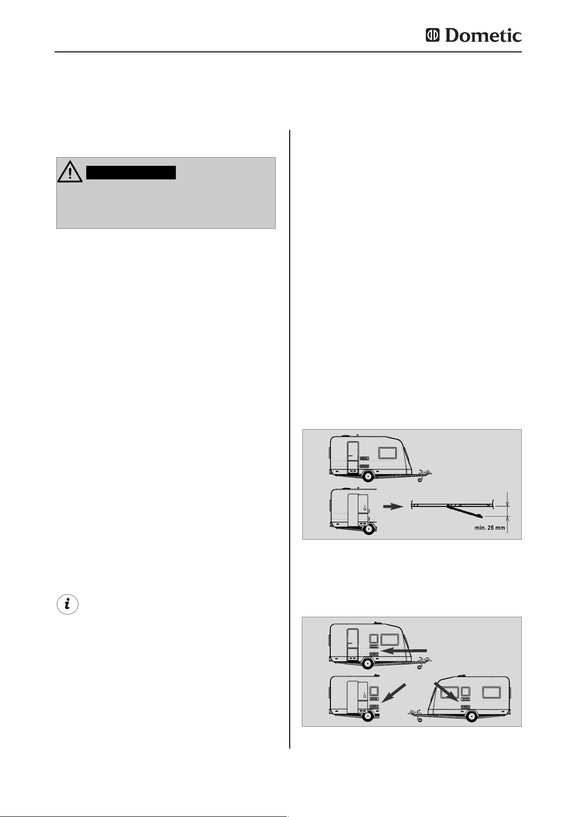
10
Montage
Même si la porte est ouverte, la chaleur du
groupe frigorifique et les gaz de combustion
peuvent s'échapper librement. (Fig. 6).
Fig. 5
Fig. 6
Grilles d'aérations
libres ! OK !
4.0 Instructions de montage
L'appareil et la conduite d'évacuation des gaz
doivent être montés de manière à être facilement accessibles pour les travaux d'entretien,
montés et démontés facilement et sortis du
véhicule sans trop d'efforts.
Lors du montage et du raccordement de l'appareil, il convient de tenir compte des prescriptions correspondant au nouvel état de la
technique :
L'installation électrique doit répondre
aux normes nationales et locales.
L'installation au gaz doit répondre aux
normes nationales et locales.
Norme européenne Norm EN 1949
Norme européennes EN 60335-1,
EN 60335-2-24, EN 1648-1 , EN 1648-2
Installez l'appareil de façon à le protéger
contre les rayonnements de chaleur
intensifs.
Les rayonnements de chaleur intensifs diminuent la performance du réfrigérateur et
entraînent une consommation accrue d'énergie !
4.1 Montage
Toute divergence de ces instructions de
montage sans accord préalable de
Dometic entraîne la suppression de la
garantie de la part de Dometic GmbH !
L'installation de l'appareil ne doit être
effectuée que par une personne qualifiée
et habilitée !
AVERTISSEMENT!
4.1.1 Montage latéral
Si l'appareil est monté du côté de la porte
d'entrée, il est impératif de veiller à ce que les
grilles d'aération ne soient pas recouvertes
par la porte ouverte. (Fig. 5, écart min. de 25
mm entre la porte et les grilles d'aération). La
ventilation est sinon restreinte, ce qui conduit
à des pertes de performance de réfrigération.
Un auvent est souvent monté du côté de la
porte du véhicule. De ce fait, l'évacuation des
gaz de combustion et de la chaleur par les
grilles d'aération est plus difficile (perte de
performance de réfrigération) !
Les grilles d'aération sont recouvertes. L'écart
entre la porte et les grilles d'aération doit être
de min. 25 mm !
Lorsque l'écart entre la porte et la grille est
entre 25 mm et 45 mm, nous recommandons
le montage du kit de ventilation Dometic
(
réf. 241 2985 - 00/0
), afin d'atteindre une
performance de réfrigération optimale lors de
températures ambiantes élevées.
Page 95

11
Montage
Fig. 7
Ouvertur
e de fond : largeur min. 50 mm,
longueur min. 520 mm
Air chaud
Condensateur
Recommandation:
Evacuateur de
toit R500
Une possibilité supplémentaire est d'installer
la ventilation du réfrigérateur au moyen de
deux équipements : une ouverture d'aération
dans le fond et un dispositif d'évacuation sur
le toit du véhicule (voir Fig. 7). Une cheminée
doit être installée entre la bordure supérieure
du réfrigérateur et l'évacuation du toit afin que
l'air chaud et éventuellement les gaz de combustion du groupe frigorifique soient directement évacués par l'évacuateur de toit.
L'ouverture du fond doit présenter une section
libre de 250 cm² min. L'ouverture doit être
pourvue d'une tôle de chicane et d'un filet afin
d'empêcher l'entrée de salissures dans la
zone du brûleur. Avec cette méthode d'aération, une quantité plus importante de salissures
peut pénétrer dans la partie arrière du réfrigérateur (comparée à la méthode d'aération latérale), c'est pourquoi une maintenance régulière du brûleur, au moins une fois par an, doit
être prévue.
Avec cette variante de montage, la maintenance régulière de l'unité du brûleur est
uniquement possible lorsque l'appareil est
démonté. Le réfrigérateur doit impérativement être installé de manière à rester facilement démontable.
C'est pourquoi nous recommandons de
prévoir une ouverture (clapet d'entretien)
sur le côté extérieur.
4.1.2 Montage latéral avec ventilation
bas-haut
Une autre variante défavorable de montage
arrière est la pose latérale de la grille d'aération et de ventilation (Fig. 10). La circulation airair chaud est très limitée, ce qui conduit à une
réfrigération insuffisante des échangeurs de
chaleur (condensateur, absorbeur). La variante
avec une grille d'aération supplémentaire
montée dans le fond se caractérise ici aussi
par une mauvaise alimentation en flux d'air.
4.1.3 Montage arrière
Le montage arrière conduit souvent à une
situation d'installation défavorable, étant
donné qu'une ventilation et une aération optimales ne sont pas toujours garanties (p. ex. la
grille d'aération du bas est recouverte par le
pare-chocs ou le feu arrière du véhicule !) (Fig.
8). La performance maximale effective de réfrigération du groupe n'est pas disponible.
Fig. 8
Fig. 9
Grilles d'aérations libres ! OK!
Grilles d'aérations
ne pas libres !
Page 96

12
Montage
Fig. 10
La performance de réfrigération maximum n'est pas disponible ! N'utilisez pas
cette possibilité de montage, car dans ce
cas, l'aération et la ventilation décrites ciaprès à la section 4.2 ne sont pas garanties !
ATTENTION!
4.1.4 Montage étanche à l'air
Les appareils frigorifiques installés dans des
caravanes, des camping-cars et autres véhicules doivent être étanches à l'air (EN 1949).
Cela signifie que l'air nécessaire au brûleur
pour la combustion n'est pas prélevé dans la
pièce et que les gaz de combustion ne peuvent pas pénétrer directement dans la pièce.
Il faut prévoir une étanchéification appropriée
entre la partie arrière du réfrigérateur et l'intérieur du véhicule.
Dometic recommande fortement d'effectuer
l'étanchéification au moyen d'un joint flexible,
afin de simplifier le démontage et remontage
ultérieurs de l'appareil pour les travaux d'entretien.
Il faut éviter à tout prix d'utiliser des masses d'étanchéité permanentes ou des
mousses de montage pour le montage
étanche à l'air du réfrigérateur ! N'utilisez
AUCUN matériau facilement inflammable
(en particulier les masses d'étanchéité au
silicone ou similaires), il y a risque d'incendie ! Dans ce cas, la garantie sur le
produit et du fabricant est supprimée.
AVERTISSEMENT!
Les joints à lèvre (1) sont placés dans la niche
d'encastrement, dans le bas et sur les côtés
(fig. 11-13). Une tôle de dissipation de chaleur
(2) est installée dans la niche d'encastrement,
au-dessus du réfrigérateur (NE PAS la fixer
sur le réfrigérateur !)
Placer la tôle de dissipation de chaleur de telle
sorte que l'air chaud s'échappe par la grille
d'aération supérieure.
Fig. 12
Fig. 11
Fig. 13
1
1
2
2
Suggestion 1
Page 97

13
L'espace situé entre la paroi extérieure du
véhicule et le réfrigérateur est étanche par rapport à la pièce. Les gaz de combustion ne
peuvent donc pas s'infiltrer dans la pièce. Ils
s'échappent à l'air libre à travers la grille supérieure d'aération et de ventilation.
Avec cette méthode de montage, la même
grille d'aération LS 200 peut être montée en
haut comme en bas, sans conduite d'évacuation des gaz. Si vous souhaitez néanmoins
une cheminée d'évacuation des gaz, montez
le système d'aération LS 100 dans l'ouverture
d'aération du haut (
Montage de la cheminée
d'évacuation des gaz, voir "4.4"
)
Les modifications ne peuvent être effectuées qu'avec l'accord du fabricant !
Dans le cas d'une température ambiante
élevée, seule une aération et ventilation
suffisante du groupe frigorifique permet à
ce dernier de développer toute sa puissance.
Il est important pour le fonctionnement de
l'appareil qu'il soit correctement installé, car,
pour des raisons physiques, de la chaleur est
générée à l'arrière de l'appareil et elle doit
pouvoir s'échapper.
4.2 Aération et ventilation du
réfrigérateur
Le réfrigérateur sera ensuite poussé par le
devant dans la niche d'encastrement. Veillez à
ce que les joints soient répartis régulièrement
sur le corps.
Le démontage du réfrigérateur pour des travaux d'entretien ou de réparation est ainsi
facilité.
Fig. 14
Fixez les lèvres d'étanchéité sur une barre de
butée au dos (1), p. ex. en les collant.
1
Suggestion 2
L'aération du groupe frigorifique est effectuée
au moyen de deux ouvertures dans la paroi de
la caravane. L'air frais pénètre par le bas et
afflue réchauffé par la grille d'aération supérieure (effet de cheminée).
Il est recommandé d'installer la grille
d'aération supérieure le plus haut possible,
au-dessus du condensateur (1, Fig. 16) .
La grille de ventilation inférieure doit être à
fleur du plancher du véhicule (Fig. 16,17),
afin que le gaz non brûlé (le gaz étant plus
lourd que l'air) puisse être directement acheminé à l'air libre.
Montage
Fig. 15
Page 98

Une installation non-conforme diminue la
performance de refroidissement et met à
risque les droits à la garantie.
ATTENTION!
14
La pose correcte de la grille d'aération inférieure facilite l'accès aux raccordements de
l'appareil et pièces fonctionnelles lors des
travaux d'entretien.
Fig. 16
1
2
1
2
Grille de ventilation LS 100 ou LS 200
Grille de ventilation LS 200
2
1
Fig. 18
Fig. 19
Le système d'aération LS 100 supérieur est
composé d'un cadre de montage (RS 1640)
(1), d'une grille d'aération avec conduite
d'évacuation des gaz (AS 1620) (2, 3) et d'une
protection d'hiver (WA120) (4). Le système
d'aération LS 200 inférieur est composé également d'un cadre de montage (RS 1650),
d'une grille d'aération (AS 1630, mais sans
conduite d'évacuation des gaz) et d'une protection d'hiver (WA130).
4.3 Montage du système
d'aération
LS 100
LS 200
1
2
3
4
Montage
Si cette disposition n'est pas possible, le
fabricant du véhicule doit impérativement
créer une ouverture d'aération dans le fond
de la niche afin que le gaz non brûlé ne
s'accumule pas au niveau du plancher.
Les grilles d'aération doivent présenter une
section libre de 250 cm² minimum. Ceci est
réalisé avec le système d'aération et de ventilation absorbeur Dometic LS 100 / LS 200, qui
a été contrôlé et autorisé dans cet objectif.
Fig. 17
1
Le brûleur à gaz doit se trouver au-dessus
du bord (1, Fig. 17) .
Page 99
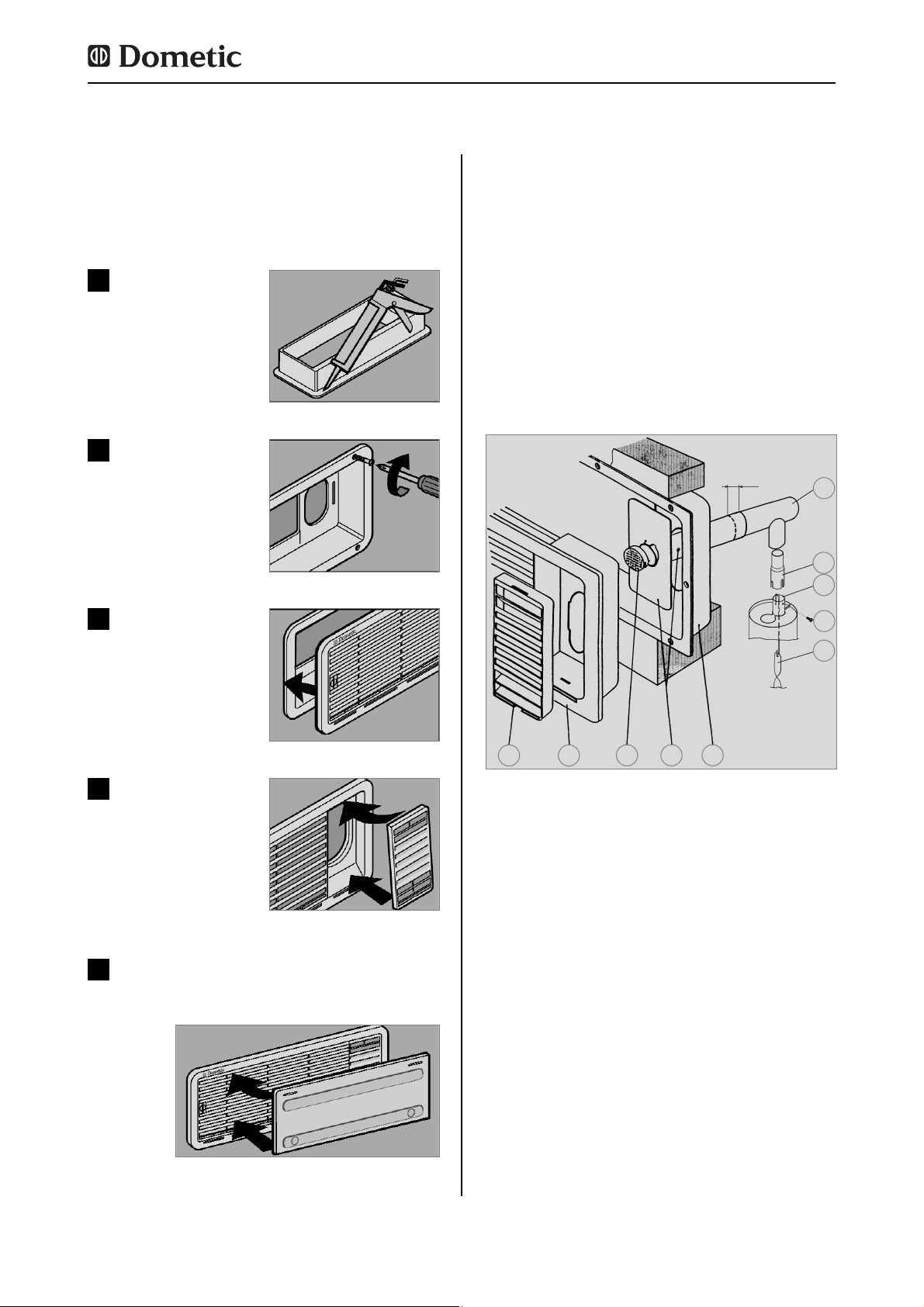
15
Fig. 20
Fig. 24
Rendre étanche à l'eau
le cadre de montage
(
n'est pas nécessaire
pour les cadres de montage avec joint intégré
).
1
Fig. 21
Mettre le cadre en place
et le visser à fond.
2
Pour le montage de la grille d'aération, faire
une découpe rectangulaire de 451 mm x 156
mm dans la paroi extérieure du véhicule.
(Voir
"4.2" pour
emplacement des découpes ).
Fig. 22
Introduire la grille d'aération dans le cadre de
montage et la verrouiller.
3
Fig. 23
Encliqueter la pièce rapportée d'évacuation des
gaz
(seulement pour le
système d'aération
supérieur LS100)
.
4
Mettre la protection d'hiver en place.
5
La conduite d'évacuation des gaz doit être
installée de façon à assurer la dérivation complète des produits de combustion vers l'extérieur de la pièce. La conduite d'évacuation des
gaz doit toujours être ascendante, afin d'éviter
l'accumulation de condensation. Sur le modèle d'évacuation des gaz présenté à la fig. 25,
la protection d'hiver peut être montée sur le
côté (10) Fig. 25.
4.4 Conduite d'évacuation des
gaz et installation de la cheminée d'évacuation des gaz
Installation de la cheminée d'évacuation
des gaz standard :
1. Placer la pièce en T (1) sur la pièce de ral-
longe (2) ou sur le tuyau d'évacuation des gaz
(3) et fixer à l'aide de la vis (4). Il faut vérifier
que le répartiteur de chaleur (5) soit dans la
position prévue à cet effet.
2. Engager le tuyau d'évacuation des gaz avec
la plaque de recouvrement (6) dans l'ouverture prévue du cadre supérieur (7) et relier avec
la pièce en T (1). Raccourcir éventuellement le
tuyau d'évacuation des gaz (6) à la bonne
longueur.
3. Placer la grille d'aération LS 100 (8) dans le
cadre de montage (7) et bloquer.
4. Enfoncer le capuchon (9) sur le tuyau d'évacuation des gaz (6).
5. Loger la pièce rapportée d'évacuation des
gaz (10) dans la grille d'aération (8).
Montage
Fig. 25
1
2
3
4
5
6 79
10
8
min. 15mm
Page 100

16
4.5.1 Emplacement dans la niche
Pousser l'appareil dans la niche jusqu'à ce
que l'avant du corps du réfrigérateur et l'avant
de la niche soient alignés. Laisser impérativement un espace de 15 à 20 mm entre la paroi
arrière de la niche et le groupe frigorifique !
Installer le réfrigérateur à l'horizontal dans
la niche.
Le réfrigérateur doit être installé dans une
niche et être étanche à l'air (voir aussi 4.1.4).
Les dimensions de la niche sont indiquées
dans le tableau ci-dessous. Le niveau (1) sert
uniquement pour les réfrigérateurs à passage
de roues.Le fond de niche doit être nivelé pour
que l'appareil puisse être aisément mis dans
sa position correcte. Le fond doit être suffisamment résistant pour supporter le poids de
l'appareil.
4.5 Niche d'encastrement
Montage
Fig. 26
T
ST
min
15-20mm
H
ST
1
Modèle Hauteur H
ST
Profond. T
ST
RMS 8400
RMS 8401
RMS 8405
RMS 8460
RMS 8461
RMS 8465
RMS 8500
RMS 8501
RMS 8505
RMS 8550
RMS 8551
RMS 8555
RMSL 8550
RMSL 8551
RMSL 8555
220 mm
220 mm
220 mm
220 mm
220 mm
220 mm
220 mm
220 mm
220 mm
220 mm
220 mm
220 mm
220 mm
220 mm
220 mm
235 mm
235 mm
235 mm
235 mm
235 mm
235 mm
235 mm
235 mm
235 mm
235 mm
235 mm
235 mm
235 mm
235 mm
235 mm
 Loading...