

Page 1
C1/C2
MENU
POWER
+
ENDEFRESPT
ITNLDASVNOFIRUPLSKCSHU
DRIVING SUPPORT
PERFECTVIEW
LCD-monitor
Montagehandleiding en
gebruiksaanwijzing . . . . . . . . . . . . . . . . . 96
LCD-monitor
Monterings- og betjeningsvejledning . . 111
LCD-monitor
Monterings- och bruksanvisning. . . . . . 124
LCD-monitor
Monterings- og bruksanvisning . . . . . . 137
LCD-monitori
Asennus- ja käyttöohje. . . . . . . . . . . . . . 150
M7LS
LCD-Monitor
Installation and Operating Manual . . . . . 11
LCD-Monitor
Montage- und Bedienungsanleitung . . . 25
Ecran LCD
Instructions de montage
et de service . . . . . . . . . . . . . . . . . . . . . . . 39
Pantalla LCD
Instrucciones de montaje y de uso . . . . . 53
Monitor LCD
Instruções de montagem e manual de
instruções . . . . . . . . . . . . . . . . . . . . . . . . . 68
Monitor LCD
Istruzioni di montaggio e d’uso . . . . . . . .82
ЖК-монитор
Инструкция по монтажу
и эксплуатации. . . . . . . . . . . . . . . . . . . . 163
Monitor LCD
Instrukcja montażu i obsługi . . . . . . . . . 177
LCD monitor
Návod na montáž a uvedenie
do prevádzky . . . . . . . . . . . . . . . . . . . . . .191
Monitor LCD
Návod k montáži a obsluze . . . . . . . . . . 203
LCD-monitor
Szerelési és használati útmutató . . . . . . 216
Page 2

Page 3
1
4
8
12 13 14
911
56 7
23
10
1
M7LS
3
Page 4
M7LS
2
3
4
5
4
Page 5
M7LS
B
A
D
C
6
7
A
10 mm
B
20 mm
C
D
8
A
B
C
D
10 mm
15 mm
5
Page 6
M7LS
A
B
9
0
a
6
Page 7
M7LS
b
7
Page 8
M7LS
C1/C2
MENU
POWER
+
1
3
2
c
C1/C2 MENU POWER
+
123
46
5
d
8
Page 9
M7LS
1
3
2
4
e
9
Page 10
1 32
7
6
11
12
13
10
9
5
8
4
C1 C2
f
M7LS
10
Page 11

M7LS Notes on using the operating manual
EN
Please read this instruction manual carefully before installation and first use, and store
it in a safe place. If you pass on the product to another person, hand over this instruction manual along with it.
Contents
1 Notes on using the operating manual . . . . . . . . . . . . . . . . . . . . . . . . . . . . . . . . . . . . . . . . . . 11
2 Safety and installation instructions . . . . . . . . . . . . . . . . . . . . . . . . . . . . . . . . . . . . . . . . . . . . . 12
3 Scope of delivery . . . . . . . . . . . . . . . . . . . . . . . . . . . . . . . . . . . . . . . . . . . . . . . . . . . . . . . . . . 14
4 Intended use . . . . . . . . . . . . . . . . . . . . . . . . . . . . . . . . . . . . . . . . . . . . . . . . . . . . . . . . . . . . . . 14
5 Technical description . . . . . . . . . . . . . . . . . . . . . . . . . . . . . . . . . . . . . . . . . . . . . . . . . . . . . . . 15
6 General information on the electrical connections . . . . . . . . . . . . . . . . . . . . . . . . . . . . . . . . 16
7 Mounting the monitor . . . . . . . . . . . . . . . . . . . . . . . . . . . . . . . . . . . . . . . . . . . . . . . . . . . . . . 17
8 Using the LCD-monitor. . . . . . . . . . . . . . . . . . . . . . . . . . . . . . . . . . . . . . . . . . . . . . . . . . . . . . 21
9 Cleaning and maintaining the LCD monitor . . . . . . . . . . . . . . . . . . . . . . . . . . . . . . . . . . . . .23
10 Guarantee . . . . . . . . . . . . . . . . . . . . . . . . . . . . . . . . . . . . . . . . . . . . . . . . . . . . . . . . . . . . . . . .23
11 Disposal. . . . . . . . . . . . . . . . . . . . . . . . . . . . . . . . . . . . . . . . . . . . . . . . . . . . . . . . . . . . . . . . . .23
12 Technical data. . . . . . . . . . . . . . . . . . . . . . . . . . . . . . . . . . . . . . . . . . . . . . . . . . . . . . . . . . . . .24
1 Notes on using the operating manual
CAUTION!
!
A
I
Safety instruction: Failure to observe this instruction can lead to injury.
NOTICE!
Failure to observe this instruction can cause material damage and impair the function
of the product.
NOTE
Supplementary information for operating the product.
11
Page 12

Safety and installation instructions M7LS
EN
2 Safety and installation instructions
Please observe the prescribed safety instructions and stipulations from the vehicle
manufacturer and service workshops.
The manufacturer accepts no liability for damage in the following cases:
• Faulty assembly or connection
• Damage to the product resulting from mechanical influences and excess voltage
• Alterations to the product without express permission from the manufacturer
• Use for purposes other than those described in the operating manual
NOTICE! Beware of damage
A
• To prevent the risk of short circuits, always disconnect the negative terminal of the
vehicle's electrical system before working on it.
If the vehicle has an additional battery, its negative terminal should also be disconnected.
• Inadequate supply cable connections could result in short circuits, causing:
–Cable fires
– The airbag being triggered
– Damage to electronic control equipment
– Electrical malfunctions (indicators, brake light, horn, ignition, lights)
Therefore, please observe the following instructions:
• When working on the following cables, only use insulated cable terminals, plugs and flat sockets:
– 30 (direct supply from positive battery terminal)
–15 (connected positive terminal, behind the battery)
– 31 (return cable from the battery, earth)
–Reversing light
Do not use porcelain wire connectors.
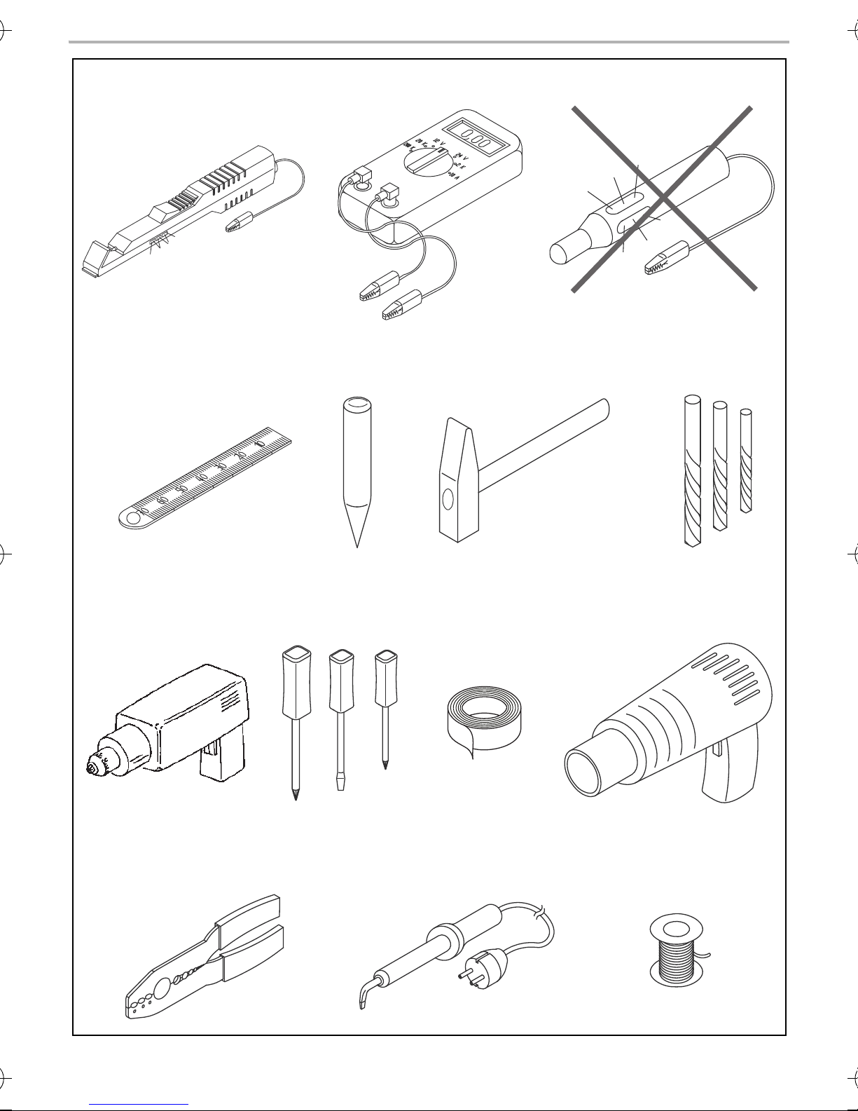
• Use a crimping tool (fig. 1 12, page 3) to connect the cables.
• Screw the cable when connecting cable 31 (earth)
– Screw on the cable using a cable terminal and serrated washer to one of the vehicle's earth
bolts or
– Screw the cable to the bodywork using a cable terminal and a self-tapping screw
Make sure there is a good earth connection.
12
Page 13

M7LS Safety and installation instructions
EN
If you disconnect the negative terminal of the battery, all data stored in the volatile memories will
be lost.
• The following data must be reset, depending on the vehicle equipment options:
–Radio code
– Vehicle clock
–Timer
– On-board computer
– Seat position
You can find instructions for making these settings in the operating manual.
Observe the following installation instructions:
CAUTION!
!
• Secure the monitor in such a way that it cannot become loose under any
circumstances (sudden braking, accidents) and cause injuries to the occupants
of the vehicle.
• Do not attach the monitor in the air bag deployment path, as this could cause injury
if the airbags are triggered.
Observe the following instructions when working with electrical parts:
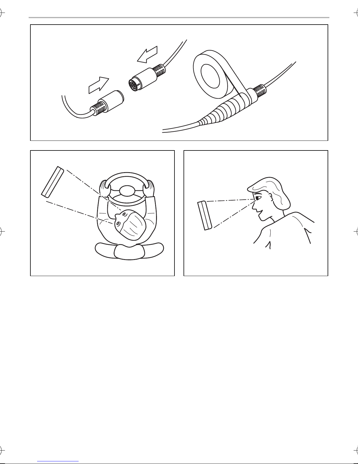
• When testing the voltage in electrical cables, only use a diode test lamp (fig. 1 1, page 3) or a
voltmeter (fig. 1 2, page 3).
Test lamps with a bulb (fig. 1 3, page 3) consume excessive current which can damage the
vehicle's electronic system.
• When making electrical connections, ensure that:
– they are not kinked or twisted
– they do not rub on edges
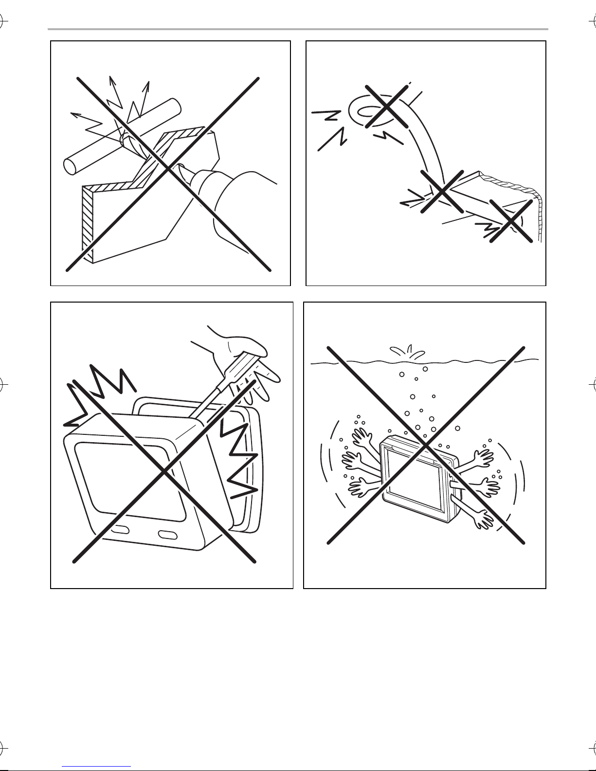
– they are not laid in sharp-edged ducts without protection (fig. 3, page 4).
• Insulate all connections.
• Secure the cables against mechanical wear by using cable binders or insulating tape, for exam-
ple on existing cables.
Observe the following instructions when handling the LCD monitor:
CAUTION!
!
• People (including children) whose physical, sensory or mental capacities or lack of
experience or knowledge prevent them from using this product safely should not
use it without the supervision or instruction of a responsible person.
• Do not open the monitor (fig. 4, page 4).
• Do not immerse the monitor in water (fig. 5, page 4); the monitor is not water-
proof.
• The monitor must not impair your vision when driving (fig. b, page 7).
• Do not operate the monitor with wet hands.
• Do not operate the monitor if the housing has been damaged.
13
Page 14

Scope of delivery M7LS
EN
NOTICE!
A
• Connect it to the correct voltage.
• Do not use the monitor in areas which
– Are subjected to direct sunlight,
– Are subject to strong temperature fluctuations,
– Have high levels of humidity,
– Are poorly ventilated,
– Are dusty or oily.
• Do not press against the LCD display.
• Do not drop the monitor.
• If you use the monitor in vehicles, the vehicle should be running during operation to
prevent the vehicle battery from discharging.
• The picture quality can be impaired in the vicinity of electromagnetic fields.
For this reason do not mount the monitor near loudspeakers.
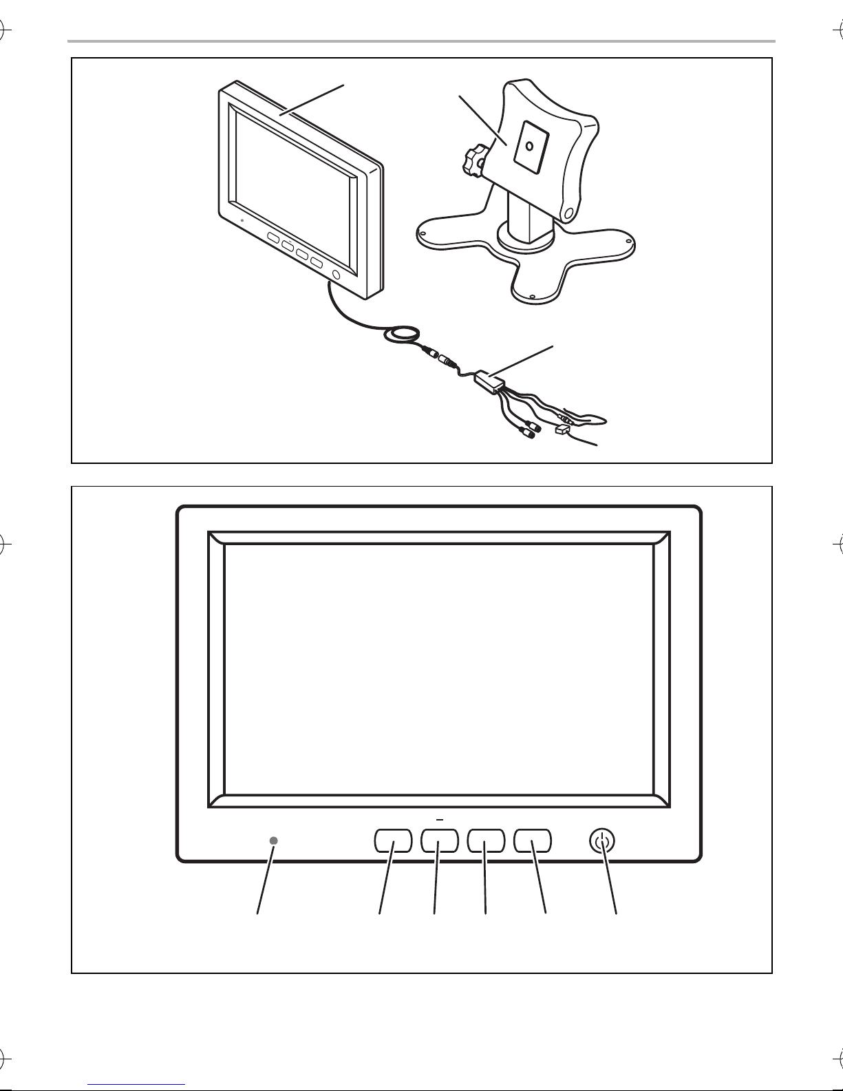
3Scope of delivery
No. in
fig. c,
page 8
1 1 Monitor M7LS 9600000204
21Monitor bracket
3 1 Connection cable 9102200027
––Fastening material
Quantity Description
Reference
number
4Intended use
The M7LS LCD monitor (item no. 9600000204) is a monitor primarily intended for use in vehicles.
It can be used to connect cameras (e. g. a reversing video system) or other video sources.
The LCD monitor is designed for use in all vehicles.
Since rear view systems are designed merely as an additional aid for reversing, it does not relieve
you of the duty to take proper care when reversing.
14
Page 15
M7LS Technical description
EN
5 Technical description
5.1 Function description
The LCD monitor is a monitor which allows cameras (e. g. a rear view video camera) or other video
sources (e. g. a TV) to be connected. It is possible to switch back and forth between video sources.
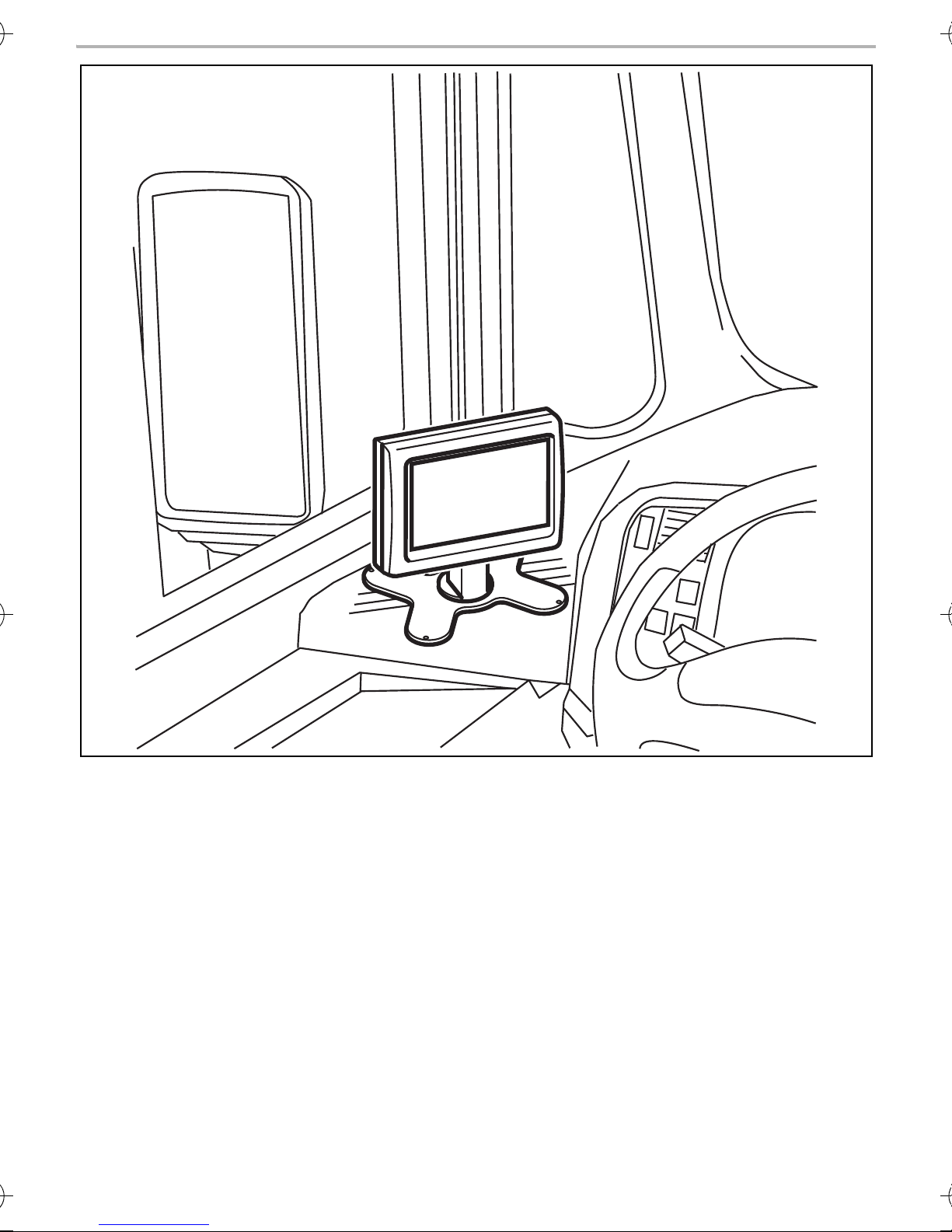
The monitor can be mounted on the dashboard, where it transmits the image from the connected
camera, allowing the driver to see the area behind the vehicle, e. g. when parking.
The brightness of the monitor adapts automatically to the ambient light.
The buttons are illuminated and can therefore also be operated in the dark.
The mirrored picture function can be activated individually for each of the two video inputs. The
image then appears as if you were looking into the rear view mirror.
5.2 Operating elements
The following control elements are located on the monitor:
No. in
fig. d,
page 8
1Light sensor
2 C1/C2 Selects the camera or swaps menu page 1 and 2.
3 – Reduces the volume or other selected parameters (bright-
4 MENU Switches to setup mode (see chapter “Using the LCD-moni-
5 + Increases the volume or other selected parameters (bright-
6 Switches the monitor on and off.
Designation Description
ness, contrast, colour tint).
tor” on page 21).
ness, contrast, colour tint).
15
Page 16

General information on the electrical connections M7LS
EN
6 General information on the electrical connections
6.1 Laying cables
NOTICE!
A
Please observe the following instructions:
• As far as possible, use original openings or alternative openings for the connecting cable duct,
e. g. the paneling edges, ventilation grilles or blank panels. If no openings are available, you
must drill holes for the cables. Check beforehand that there is sufficient space on the other side
for the drill head to come out.
• Wherever possible lay cables inside the vehicle, as they are better protected there than outside
the vehicle.
If you do need to lay a cable outside the vehicle, ensure that it is well secured (use additional
cable ties, insulating tape, etc.).
Cables and connections which are not properly installed will cause malfunctions or
damage to components. Correct installation of cables and connections ensures lasting
and trouble-free operation of the retrofitted components.
• To prevent damage to the cables, when laying them, ensure that they are far enough away from
hot or moving vehicle components (exhaust pipes, drive shafts, light systems, fans, heater etc.).
• Wrap insulating tape around the plug connections of the connecting cables and every connection on a cable (including inside the vehicle) to protect them from exposure to water (fig. 9,
page 6). The most suitable tape for this purpose is self-vulcanising tape, for example from 3M.
• When laying electric connections (fig. 3, page 4), ensure that
– They are not kinked or twisted
– They do not rub on edges
– They are not laid in sharp edged ducts without protection
• Attach the cables securely in the vehicles to prevent tripping hazards. Use cable binders, insulating tape or glue the cables in place.
• Protect every through-hole made in the bodywork against water penetration, e. g. by using a
cable with a sealant and by spraying the cable and the the cable sleeve with sealant.
NOTE
I
Do not start sealing the through-holes until you have completed all installation work on
the camera, and the required cable lengths have been laid.
16
Page 17

M7LS Mounting the monitor
EN
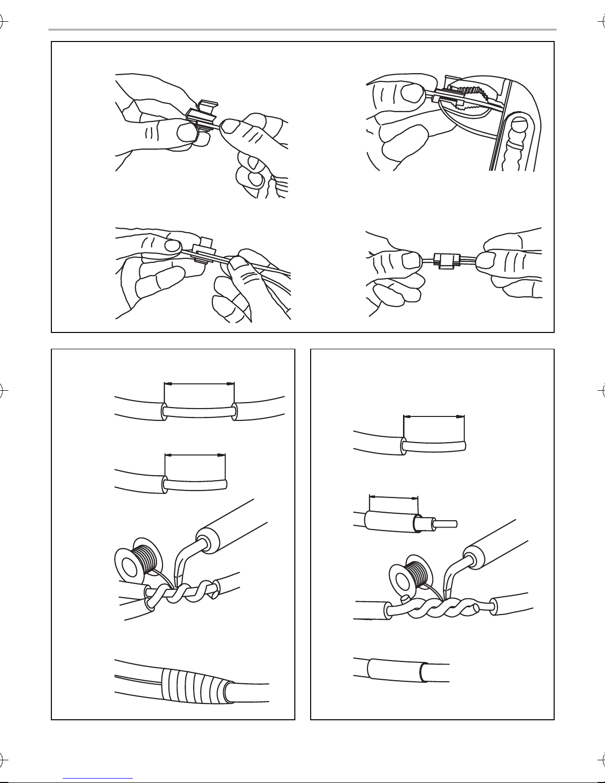
6.2 Using branch connectors (fig. 6, page 5)
To prevent loose connections in the branch connectors, it is important to ensure that the cable
cross sections fit into the branch connectors.
To use the branch connectors, proceed as follows:
➤ Insert the cable to be tapped in the front groove of the cable connector (A).
➤ Insert the end of the new cable up to approx. 3/4 of the way into the rear groove (B).
➤ Use a pair of combination pliers to close the connector by pressing the metal pin in. This cre-
ates an electrical connection (C).
➤ Press down the safety cap until it snaps into place.
➤ Check that the connection is secure by lightly tugging the cable (D).
6.3 Creating clean soldering joints
Proceed as follows to solder a cable to the original cables (fig. 7, page 5):
➤ Strip approx. 10 mm of insulation from the end of the original cable (A).
➤ Strip approx. 15 mm of insulation from the end of the cable to be connected (B).
➤ Wind the cable to be connected around the original cable and solder the two cables together
(C).
➤ Insulate the two cables with insulating tape (D).
Proceed as follows to solder two cables together (fig. 8, page 5):
➤ Strip the two cables (A).
➤ Place a shrink sleeve with a length of approx. 20 mm over the cable (B).
➤ Twist the cables together and solder them (C).
➤ Place a shrink sleeve over the soldered point and heat it briefly (D).
7 Mounting the monitor
7.1 Tools required (fig. 1, page 3)
For installation and assembly you will need the following tools:
• Measuring ruler (4)
• Centre punch (5)
• Hammer (6)
• Drill bit set (7)
• Drill (8)
• Screwdriver (9)
17
Page 18

Mounting the monitor M7LS
EN
To make and test the electrical connection, the following tools are required:
• Diode test lamp (1) or voltmeter (2)
• Insulating tape (10)
• Heat shrinking sleeve
• Hot air blower (11)
• Crimping tool (12)
• Soldering iron (optional) (13)
• Solder (optional) (14)
• Cable bushing sleeves (optional)
Depending on the individual installation requirements you may require bolts, nuts, washers, selftapping screws and cable binders other than those including in the scope of delivery.
7.2 Installing the monitor
CAUTION! Risk of injury!
!
Observe the following installation instructions:
• Select an installation location that provides an unobstructed view of the monitor (fig. 0,
page 6 and fig. a, page 6).
• Never install the monitor in area where your head could impact it or in the air bag deployment
path. This could cause injury if the airbag opens.
• The monitor must not impair your vision when driving (fig. b, page 7).
• The installation location should be flat.
• Check that there is sufficient space underneath the installation location to attach the washers
and nuts.
• Check beforehand that there is sufficient space on the other side for the drill head to come out.
• Bear in mind the weight of the monitor. Provide reinforcement if necessary (larger washers or
plates).
Select the location of the monitor so that it cannot injure the passengers in the vehicle
under any circumstances (e. g. sudden braking, road traffic accidents).
• Ensure that you can lay the connection cable set to the monitor.
18
Page 19

M7LS Mounting the monitor
EN
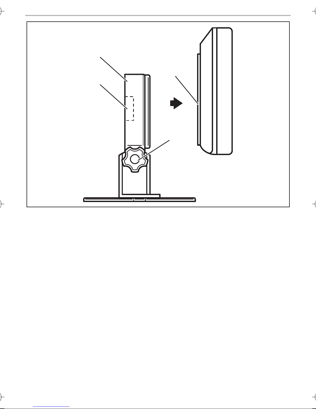
To perform the installation, proceed as follows (fig. e, page 9):
➤ Slide the monitor (1) onto the mounting plate of the monitor bracket (2) and secure it on the
monitor bracket with the knurled screw (3).
➤ Position the monitor and the attached monitor bracket for testing.
➤ Mark the outlines of the corners of the monitor bracket (2) on the dashboard.
➤ Unscrew the monitor from the monitor holder.
➤ Hold the monitor bracket within the outlines marked beforehand and mark four different drill-
ing points.
➤ Drill Ø 2 mm holes at the points you have just marked.
➤ Screw on the monitor bracket with the 4 x 20 mm self-tapping screws.
➤ Slide the monitor (1) onto the mounting plate of the monitor bracket (2) and secure it on the
monitor bracket with the knurled screw (3).
NOTE
I
You can now adjust the angle of inclination. To do this, loosen the knurled screw (4)
and tilt the monitor to the desired position. Tighten the knurled screw (4).
7.3 Laying the system cable from the camera to the monitor
NOTE
I
➤ Lay the system cable for the camera inside the vehicle.
➤ Lay the system cable for the camera to the monitor.
➤ Connect the monitor connection cable to the system cable.
➤ Insulate the plug connection with the insulating tape supplied. Overlap every layer of the insu-
lating tape by one half of its width.
➤ Attach the cables securely in the vehicles to prevent tripping hazards. This can be performed
by using cable binders, insulating tape or gluing in place with adhesives.
I
Lay the camera cable so that should you need to remove the camera, you can access
the plug connection between the camera and the extension cable easily. This greatly
facilitates the disassembly.
NOTE
Only start sealing through-holes when you have completed all installation work on the
camera and have laid the required cable lengths.
19
Page 20
Mounting the monitor M7LS
EN
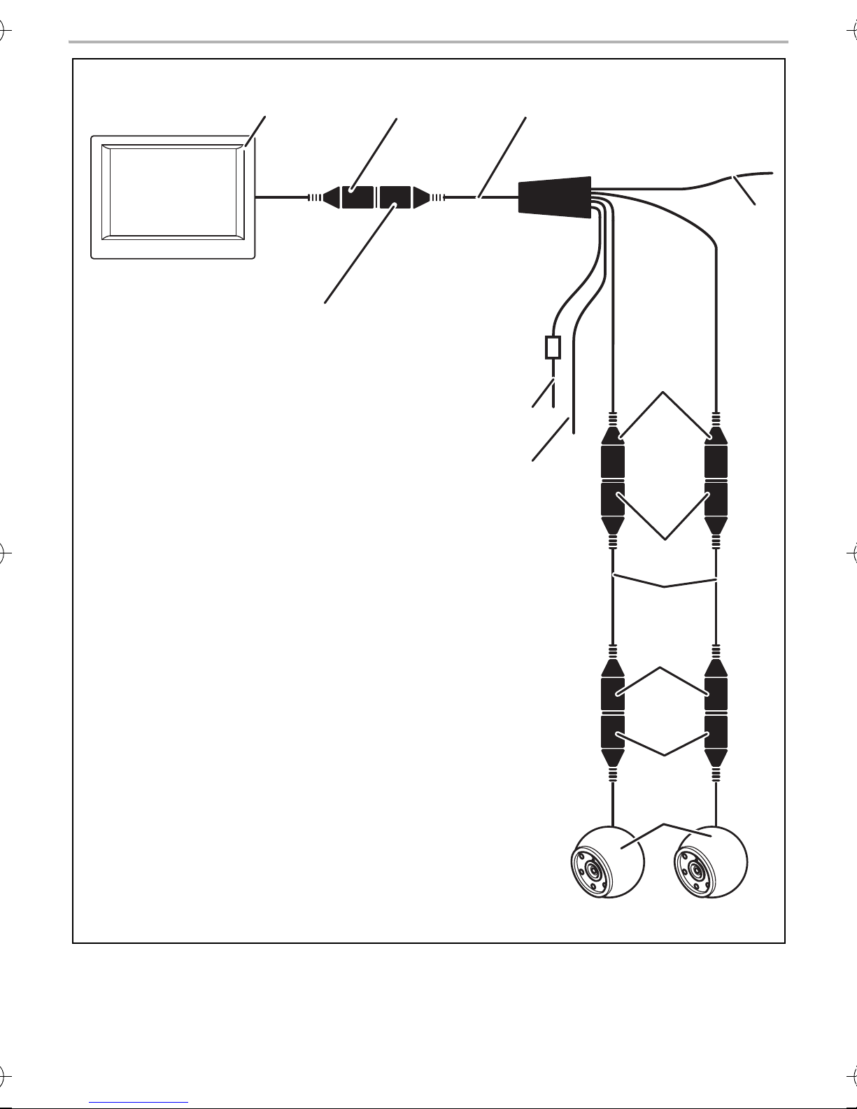
7.4 Connecting the monitor to an electricity supply (fig. f, page 10)
The circuit diagram for the monitor can be found in fig. f, page 10.
No. Description
1Monitor
2 13-pin DIN plug
3Connection cable
413-pin DIN socket
5 12 V positive cable (red): Connection to the positive pole of the voltage source
6 Earth cable (black): Connection to the negative pole of the voltage source
76-pin DIN socket
8 Cable (green): Control input for the connection to the reversing lights
96-pin mini DIN plug
10 System cable
11 6-pin mini DIN socket
12 6-pin mini DIN plug
13 Camera
Observe the following instructions when laying the connection cable:
• Feed the connection cable through existing ducts or other openings where possible e. g. ventilation grilles. If no appropriate ducts or openings are available you will need to drill a hole of
18 mm. Check beforehand that there is sufficient space on the other side for the drill head to
come out (fig. 2, page 4).
• Please observe the notes from the chapter “General information on the electrical connections”
on page 16.
➤ Lay the monitor cable on the dashboard.
➤ Insert the plug of the monitor cable (2) in the socket (4) of the connection cable (3).
NOTICE!
A
Make sure the polarity is correct when connecting to a voltage source.
➤ Connect the red and black cables of the connection cables to a suitable voltage source:
– Connect the red cable (5) to terminal 15 (ignition).
– Connect the black cable (6) to terminal 31 (earth).
➤ If necessary, connect the mini DIN socket (7) of the connection cable to the mini DIN plug (9)
of the system cable (10).
20
Page 21

M7LS Using the LCD-monitor
EN
➤ Connect the mini DIN socket (11) of the system cable (10) of to the mini DIN plug (12) of the
camera cable.
➤ Connect the green cable (8) to the positive cable of the reversing light.
NOTE
I
If a voltage is present on the green cable, the monitor is switched on automatically and
the camera is activated.
8 Using the LCD-monitor
8.1 Switching on the monitor (fig. d, page 8)
NOTE
I
The monitor is switched on automatically, if you shift into reverse gear. The image is
transmitted by the camera.
➤ If the monitor is switched off, press the “Power” main switch (6), to switch the monitor on.
✓ The picture appears.
✓ The brightness of the display is automatically adapted to the ambient light.
8.2 Switching off the monitor (fig. d, page 8)
➤ Press the main switch “Power” (6), to switch off the monitor.
✓ The picture disappears.
8.3 Setting the volume (fig. d, page 8)
You can set the volume to amplify or mute the the noises transmitted by the camera.
➤ Press the “–” button (3) to reduce the volume.
➤ Press the “+” button (5) to increase the volume.
21
Page 22

Using the LCD-monitor M7LS
EN
8.4 Setting the monitor (fig. d, page 8)
To set the monitor to suit your requirements, proceed as follows:
➤ Press the “MENU” button (3) to call up the required parameter.
✓ The parameters to be set appear in the following order:
Page 1:
– Brightness: 0 – 100
–Contrast: 0 – 100
– Colour: 0 – 100
– Language: “English” or “German”
Page 2:
– Reset (“Default”): Default setting for all parameters
– Camera 1: “Normal” or “Mirrored”
– Camera 2: “Normal” or “Mirrored”
➤ Press the “–” button (4) or “+” button (5) to set the parameter of your choice.
➤ Press the “–” button (4) to reduce the value of the selected parameter.
➤ Press the “+” button (5) to increase the value of the selected parameter.
8.5 Setting the video source (fig. d, page 8)
NOTE
I
➤ If you wish to switch to a different video source (from camera 1 to camera 2), press the
“C1/C2” button (2).
✓ The monitor switches from camera 1 to camera 2 or vice-versa.
If you have connected the green cable to the reversing light and voltage is present,
reversing camera V1 is activated automatically.
22
Page 23

M7LS Cleaning and maintaining the LCD monitor
EN
9 Cleaning and maintaining the LCD monitor
NOTICE!
A
➤ Occasionally clean the product with a damp cloth.
• Do not use sharp or hard objects or cleaning agents for cleaning as these may damage the product.
• Remove the cable before cleaning the monitor to prevent short circuiting.
10 Guarantee
The statutory warranty period applies. If the product is defective, please contact the
manufacturer's branch in your country (see the back of the instruction manual for the addresses) or
your retailer.
For repair and guarantee processing, please include the following documents when you send in
the device:
• A copy of the receipt with purchasing date
• A reason for the claim or description of the fault
11 Disposal
➤ Place the packaging material in the appropriate recycling waste bins wherever possible.
If you wish to finally dispose of the product, ask your local recycling centre or specialist
dealer for details about how to do this in accordance with the applicable disposal
M
regulations.
23
Page 24
Technical data M7LS
EN
13
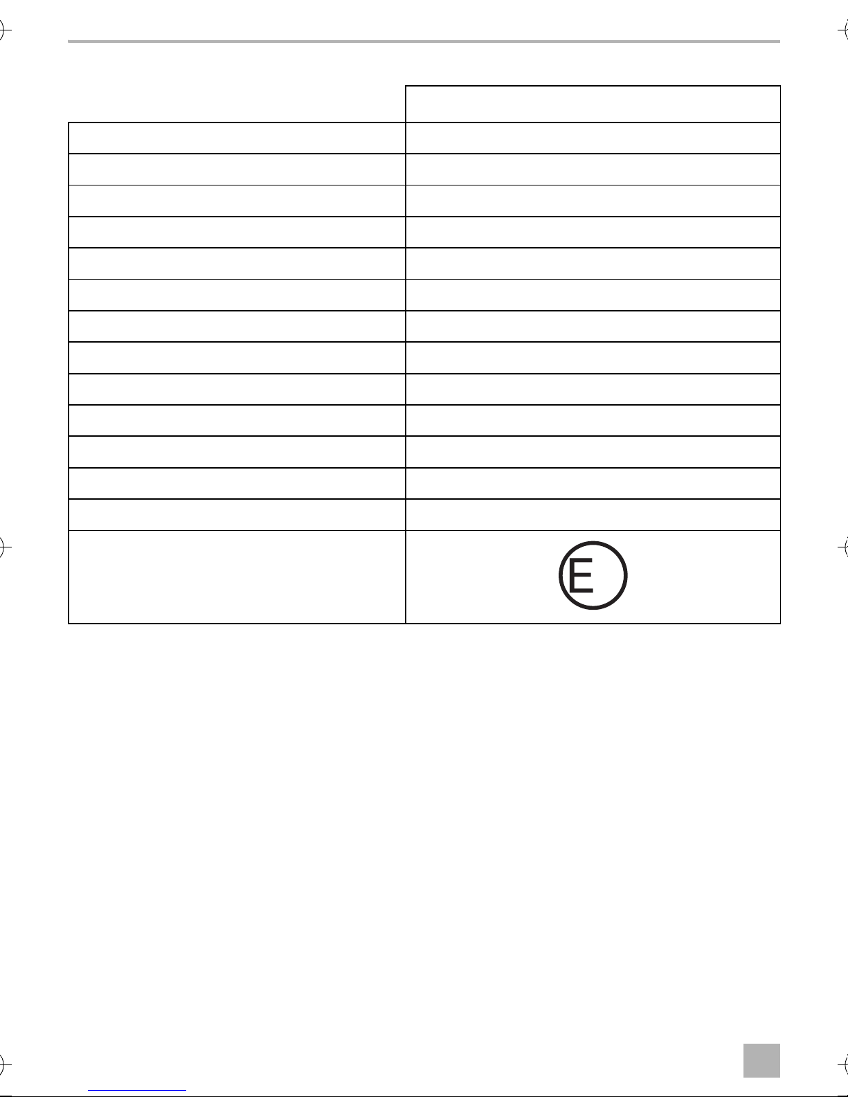
12 Technical data
M7LS
Reference no.: 9600000204
Type: Colour TFT LCD
Display size: 7" (17.8 cm)
Brightness: Approx. 300 cd/m²
Display resolution, H x V: 337000 pixels
Operating voltage: 11 – 16 Vg
Power: Max. 8 W
Operating temperature: –20 °C to +65 °C
Storage temperature: –25 °C to +80 °C
Relative humidity: Max. 85 %
Vibration resistance: 5 g
Dimensions (W x H x D): 170 x 125 x 25 mm
Weight: 400 g
Approval:
24
Page 25

M7LS Hinweise zur Benutzung der Anleitung
DE
Bitte lesen Sie diese Anleitung vor Einbau und Inbetriebnahme sorgfältig durch und
bewahren Sie sie auf. Geben Sie sie im Falle einer Weitergabe des Produktes an den
Nutzer weiter.
Inhaltsverzeichnis
1 Hinweise zur Benutzung der Anleitung. . . . . . . . . . . . . . . . . . . . . . . . . . . . . . . . . . . . . . . . .25
2 Sicherheits- und Einbauhinweise. . . . . . . . . . . . . . . . . . . . . . . . . . . . . . . . . . . . . . . . . . . . . .26
3 Lieferumfang . . . . . . . . . . . . . . . . . . . . . . . . . . . . . . . . . . . . . . . . . . . . . . . . . . . . . . . . . . . . . .28
4 Bestimmungsgemäßer Gebrauch . . . . . . . . . . . . . . . . . . . . . . . . . . . . . . . . . . . . . . . . . . . . .29
5 Technische Beschreibung . . . . . . . . . . . . . . . . . . . . . . . . . . . . . . . . . . . . . . . . . . . . . . . . . . .29
6 Allgemeine Hinweise zum elektrischen Anschluss . . . . . . . . . . . . . . . . . . . . . . . . . . . . . . . .30
7 Monitor montieren . . . . . . . . . . . . . . . . . . . . . . . . . . . . . . . . . . . . . . . . . . . . . . . . . . . . . . . . .32
8 LCD-Monitor benutzen. . . . . . . . . . . . . . . . . . . . . . . . . . . . . . . . . . . . . . . . . . . . . . . . . . . . . .35
9 LCD-Monitor pflegen und reinigen . . . . . . . . . . . . . . . . . . . . . . . . . . . . . . . . . . . . . . . . . . . .37
10 Gewährleistung . . . . . . . . . . . . . . . . . . . . . . . . . . . . . . . . . . . . . . . . . . . . . . . . . . . . . . . . . . .37
11 Entsorgung . . . . . . . . . . . . . . . . . . . . . . . . . . . . . . . . . . . . . . . . . . . . . . . . . . . . . . . . . . . . . . .37
12 Technische Daten . . . . . . . . . . . . . . . . . . . . . . . . . . . . . . . . . . . . . . . . . . . . . . . . . . . . . . . . . .38
1 Hinweise zur Benutzung der Anleitung
VORSICHT!
!
A
I
Sicherheitshinweis: Nichtbeachtung kann zu Verletzungen führen.
ACHTUNG!
Nichtbeachtung kann zu Materialschäden führen und die Funktion des Produktes
beeinträchtigen.
HINWEIS
Ergänzende Informationen zur Bedienung des Produktes.
➤ Handlung: Dieses Symbol zeigt Ihnen, dass Sie etwas tun müssen. Die erforderlichen Hand-
lungen werden Schritt für Schritt beschrieben.
✓ Dieses Symbol beschreibt das Ergebnis einer Handlung.
Abb. 1 5, Seite 3: Diese Angabe weist Sie auf ein Element in einer Abbildung hin, in diesem
Beispiel auf „Position 5 in Abbildung 1 auf Seite 3“.
25
Page 26

Sicherheits- und Einbauhinweise M7LS
DE
2 Sicherheits- und Einbauhinweise
Beachten Sie die vom Fahrzeughersteller und vom Kfz-Handwerk
vorgeschriebenen Sicherheitshinweise und Auflagen!
Der Hersteller übernimmt in folgenden Fällen keine Haftung für Schäden:
• Montage- oder Anschlussfehler
• Beschädigungen am Produkt durch mechanische Einflüsse und Überspannungen
• Veränderungen am Produkt ohne ausdrückliche Genehmigung vom Hersteller
• Verwendung für andere als die in der Anleitung beschriebenen Zwecke
ACHTUNG! Beschädigungsgefahr!
A
• Klemmen Sie wegen der Kurzschlussgefahr vor Arbeiten an der Fahrzeugelektrik
immer den Minuspol ab.
Bei Fahrzeugen mit Zusatzbatterie müssen Sie an dieser ebenfalls den Minuspol
abklemmen.
• Unzureichende Leitungsverbindungen können zur Folge haben, dass durch Kurzschluss
– Kabelbrände entstehen,
– der Airbag ausgelöst wird,
– elektronische Steuerungseinrichtungen beschädigt werden,
– elektrische Funktionen ausfallen (Blinker, Bremslicht, Hupe, Zündung, Licht).
Beachten Sie deshalb folgende Hinweise:
• Verwenden Sie bei Arbeiten an den folgenden Leitungen nur isolierte Kabelschuhe, Stecker
und Flachsteckhülsen:
– 30 (Eingang von Batterie Plus direkt)
– 15 (Geschaltetes Plus, hinter Batterie)
– 31 (Rückleitung ab Batterie, Masse)
–Rückfahrscheinwerfer
Verwenden Sie keine Lüsterklemmen.
• Verwenden Sie eine Krimpzange (Abb. 1 12, Seite 3) zum Verbinden der Kabel.
• Schrauben Sie das Kabel bei Anschlüssen an Leitung 31 (Masse)
– mit Kabelschuh und Zahnscheibe an eine fahrzeugeigene Masseschraube oder
– mit Kabelschuh und Blechschraube an das Karosserieblech.
Achten Sie auf eine gute Masseübertragung!
26
Page 27

M7LS Sicherheits- und Einbauhinweise
DE
Beim Abklemmen des Minuspols der Batterie verlieren alle flüchtigen Speicher der Komfortelektronik ihre gespeicherten Daten.
• Folgende Daten müssen Sie je nach Fahrzeugausstattung neu einstellen:
–Radiocode
–Fahrzeuguhr
– Zeitschaltuhr
– Bordcomputer
– Sitzposition
Hinweise zur Einstellung finden Sie in der jeweiligen Bedienungsanleitung.
Beachten Sie folgende Hinweise bei der Montage:
VORSICHT!
!
• Befestigen Sie den Monitor so, dass er sich unter keinen Umständen (scharfes
Abbremsen, Verkehrsunfall) lösen und zu Verletzungen der Fahrzeuginsassen
führen kann.
• Befestigen Sie den Monitor nicht im Wirkungsbereich eines Airbags, da bei Auslösung sonst Verletzungsgefahr besteht.
Beachten Sie folgende Hinweise bei der Arbeit an elektrischen Teilen:
• Benutzen Sie zum Prüfen der Spannung in elektrischen Leitungen nur eine Diodenprüflampe
(Abb. 1 1, Seite 3) oder ein Voltmeter (Abb. 1 2, Seite 3).
Prüflampen mit einem Leuchtkörper (Abb. 1 3, Seite 3) nehmen zu hohe Ströme auf,
wodurch die Fahrzeugelektronik beschädigt werden kann.
• Beachten Sie beim Verlegen der elektrischen Anschlüsse, dass diese
– nicht geknickt oder verdreht werden,
–nicht an Kanten scheuern,
– nicht ohne Schutz durch scharfkantige Durchführungen verlegt werden (Abb. 3, Seite 4).
• Isolieren Sie alle Verbindungen und Anschlüsse.
• Sichern Sie die Kabel gegen mechanische Beanspruchung durch Kabelbinder oder Isolier-
band, z. B. an vorhandenen Leitungen.
27
Page 28

Lieferumfang M7LS
DE
Beachten Sie folgende Hinweise beim Umgang mit dem LCD-Monitor:
VORSICHT!
!
A
• Personen (einschließlich Kinder), die aufgrund ihrer physischen, sensorischen oder
geistigen Fähigkeiten oder ihrer Unerfahrenheit oder Unkenntnis nicht in der Lage
sind, das Produkt sicher zu benutzen, sollten dieses Produkt nicht ohne Aufsicht
oder Anweisung durch eine verantwortliche Person nutzen.
• Öffnen Sie den Monitor nicht (Abb. 4, Seite 4).
• Tauchen Sie den Monitor keinesfalls in Wasser (Abb. 5, Seite 4); der Monitor ist
nicht wasserdicht.
• Der Monitor darf auf keinen Fall die Sicht beim Autofahren behindern (Abb. b,
Seite 7).
• Bedienen Sie den Monitor nicht mit nassen Händen.
• Nehmen Sie den Monitor außer Betrieb, wenn das Gehäuse beschädigt ist.
ACHTUNG!
• Schließen Sie die korrekte Spannung an.
• Benutzen Sie den Monitor nicht in Umgebungen, die
– direkter Sonnenstrahlung ausgesetzt sind,
– starken Temperaturschwankungen unterliegen,
– eine hohe Luftfeuchtigkeit aufweisen,
– eine schlechte Ventilation haben,
– staubig oder ölig sind.
• Drücken Sie nicht auf das LCD-Display.
• Lassen Sie den Monitor nicht fallen.
• Wenn Sie den Monitor in Fahrzeugen einsetzen, sollte das Fahrzeug während des
Betriebs laufen, damit die Starterbatterie nicht entladen wird.
• Die Bildqualität kann sich verschlechtern, wenn starke elektromagnetische Felder in
der Nähe sind.
Montieren Sie den Monitor deshalb nicht in der Nähe von Lautsprechern.
3Lieferumfang
Nr. in
Abb. c,
Seite 8
1 1 Monitor M7LS 9600000204
21Monitorhalter
3 1 Anschlusskabel 9102200027
––Befestigungsmaterial
28
Menge Bezeichnung Artikel-Nr.
Page 29

M7LS Bestimmungsgemäßer Gebrauch
DE
4 Bestimmungsgemäßer Gebrauch
Der LCD-Monitor M7LS (Art.-Nr. 9600000204) ist ein Monitor, der vorrangig für den Einsatz in
Fahrzeugen gedacht ist. Er kann verwendet werden, um Kameras (z. B. Rückfahrvideosystem)
oder andere Videoquellen anzuschließen.
Der LCD-Monitor ist für den Einsatz in allen Fahrzeugen ausgelegt.
Rückfahrvideosysteme stellen eine Unterstützung beim Rückwärtsfahren dar, sie entbinden Sie
jedoch nicht von der besonderen Vorsichtspflicht beim Rückwärtsfahren.
5 Technische Beschreibung
5.1 Funktionsbeschreibung
Der LCD-Monitor ist ein Monitor, an den Kameras (z. B. Rückfahrvideosystem) oder andere Videoquellen (z. B. TV-Gerät) angeschlossen werden können. Zwischen den Videoquellen kann hin- und
hergeschaltet werden.
Der Monitor kann am Armaturenbrett befestigt werden und überträgt das Bild der angeschlossenen Kameras, so dass der Fahrer den Raum hinter dem Fahrzeug einsehen kann, z. B. beim Einparken.
Die Helligkeit des Monitors passt sich automatisch dem Umgebungslicht an.
Die Tasten sind beleuchtet und somit auch im Dunkeln bedienbar.
Für jeden der beiden Videoeingänge kann die Spiegelfunktion getrennt aktiviert werden. Sie
sehen das Bild dann so, als ob Sie in den Rückspiegel blicken.
5.2 Bedienelemente
Am Monitor finden Sie folgende Bedienelemente:
Nr. in
Abb. d,
Seite 8
1Lichtsensor
2 C1/C2 Wählt die Kamera aus oder wechselt zwischen Menüseite 1
3 – Verringert die Lautstärke oder den ausgewählten Parame-
Bezeichnung Beschreibung
und 2.
ter (Helligkeit, Kontrast, Farbton).
4 MENU Schaltet in den Einstellmodus (siehe Kapitel „LCD-Monitor
5 + Erhöht die Lautstärke oder den ausgewählten Parameter
6 Schaltet den Monitor ein und aus.
benutzen“ auf Seite 35).
(Helligkeit, Kontrast, Farbton).
29
Page 30

Allgemeine Hinweise zum elektrischen Anschluss M7LS
DE
6 Allgemeine Hinweise zum elektrischen Anschluss
6.1 Kabel verlegen
ACHTUNG!
A
Beachten Sie deshalb folgende Hinweise:
• Verwenden Sie für die Durchführung der Anschlusskabel nach Möglichkeit Originaldurchführungen oder andere Durchführungsmöglichkeiten, z. B. Verkleidungskanten, Lüftungsgitter oder Blindschalter. Wenn keine Durchführungen vorhanden sind, müssen Sie für
die jeweiligen Kabel entsprechende Löcher bohren. Schauen Sie vorher nach, ob ausreichender Freiraum für den Bohreraustritt vorhanden ist.
• Verlegen Sie die Kabel nach Möglichkeit immer im Fahrzeuginneren, denn dort sind sie besser
geschützt als außen am Fahrzeug.
Wenn Sie die Kabel trotzdem außerhalb des Fahrzeuges verlegen, achten Sie auf eine sichere
Befestigung (durch zusätzliche Kabelbinder, Isolierband usw.).
Nicht fachgerechte Kabelverlegungen und Kabelverbindungen führen immer wieder
zu Fehlfunktionen oder Beschädigungen von Bauteilen. Eine korrekte Kabelverlegung
bzw. Kabelverbindung ist die Grundvoraussetzung für eine dauerhafte und fehlerfreie
Funktion der nachgerüsteten Komponenten.
• Um Beschädigungen am Kabel zu vermeiden, halten Sie beim Verlegen der Kabel immer ausreichend Abstand zu heißen und sich bewegenden Fahrzeugteilen (Auspuffrohre, Antriebswellen, Lichtmaschine, Lüfter, Heizung usw.).
• Umwickeln Sie die Steckverbindungen der Verbindungskabel zum Schutz gegen das Eindringen von Wasser und jede Verbindung an einem Kabel (auch im Fahrzeug) dicht mit einem
guten Isolierband (Abb. 9, Seite 6). Am besten eignet sich selbstvulkanisierendes Dichtband,
z. B. von 3M.
• Beachten Sie beim Verlegen der Kabel (Abb. 3, Seite 4), dass diese
– nicht stark geknickt oder verdreht werden
–nicht an Kanten scheuern
– nicht ohne Schutz durch scharfkantige Durchführungen verlegt werde.
• Befestigen Sie die Kabel sicher im Fahrzeug, um ein Verfangen (Sturzgefahr) zu vermeiden. Dieses kann erfolgen durch den Einsatz von Kabelbindern, Isolierband oder durch Ankleben mit
Klebstoff.
• Schützen Sie jeden Durchbruch an der Außenhaut durch geeignete Maßnahmen gegen Wassereinbruch, z. B. durch Einsetzen des Kabels mit Dichtungsmasse und durch Abspritzen des
Kabels und der Durchführungstülle mit Dichtungsmasse.
HINWEIS
I
Beginnen Sie mit dem Abdichten der Durchbrüche erst, nachdem alle Einstellarbeiten
an der Kamera abgeschlossen sind und die benötigten Längen der Anschlusskabel
festliegen.
30
Page 31

M7LS Allgemeine Hinweise zum elektrischen Anschluss
DE
6.2 Abzweigverbinder verwenden (Abb. 6, Seite 5)
Um Wackelkontakte bei den Abzweigverbindungen zu vermeiden, achten Sie darauf, dass die
Kabelquerschnitte zu den Abzweigverbindern passen.
Gehen Sie wie folgt vor, um die Abzweigverbinder zu verwenden:
➤ Legen Sie das Kabel, das angezapft werden soll, in die vordere Rille des Abzweigverbinders
(A).
➤ Legen Sie das neue Kabel mit dem Ende zu ca. 3/4 in die hintere Rille (B).
➤ Schließen Sie den Verbinder und drücken Sie mit einer Kombizange den Metallsteg in den
Verbinder, so dass eine Stromverbindung hergestellt wird (C).
➤ Drücken Sie die Schutzkappe herunter und lassen Sie sie am Verbinder einrasten.
➤ Prüfen Sie die Befestigung der Abzweigverbindung durch Ziehen am Kabel (D).
6.3 Korrekte Lötverbindungen erstellen
Gehen Sie wie folgt vor, um ein Kabel an Originalleitungen anzulöten (Abb. 7, Seite 5):
➤ Isolieren Sie 10 mm aus der Originalleitung ab (A).
➤ Isolieren Sie 15 mm vom anzuschließenden Kabel ab (B).
➤ Wickeln Sie das anzuschließende Kabel um die Originalleitung und verlöten Sie die beiden
Kabel (C).
➤ Isolieren Sie die Kabel mit Isolierband (D).
Gehen Sie wie folgt vor, um zwei Kabel miteinander zu verbinden (Abb. 8, Seite 5):
➤ Isolieren Sie beide Kabel ab (A).
➤ Ziehen Sie einen Schrumpfschlauch von ca. 20 mm Länge über ein Kabel (B).
➤ Verdrehen Sie beide Kabel miteinander und verlöten Sie sie (C).
➤ Schieben Sie den Schrumpfschlauch über die Lötstelle und erwärmen sie ihn leicht (D).
31
Page 32

Monitor montieren M7LS
DE
7 Monitor montieren
7.1 B enö tigtes Werkzeug ( Abb. 1, Seite 3)
Für Einbau und Montage benötigen Sie folgende Werkzeuge:
• Maßstab (4)
• Körner (5)
• Hammer (6)
• Satz Bohrer (7)
• Bohrmaschine (8)
• Schraubendreher (9)
Für den elektrischen Anschluss und seine Überprüfung benötigen Sie folgende Hilfsmittel:
• Diodenprüflampe (1) oder Voltmeter (2)
• Isolierband (10)
• Wärmeschrumpfschlauch
• Heißluftföhn (11)
• Krimpzange (12)
• Ggf. Lötkolben (13)
• Ggf. Lötzinn (14)
• Ggf. Kabeldurchführungstüllen
Abhängig von der individuellen Montage benötigen Sie zur Befestigung eventuell noch andere
Schrauben, Muttern, Unterlegscheiben und Kabelbinder als die im Lieferumfang enthaltenen.
7.2 Monitor montieren
VORSICHT! Verletzungsgefahr!
!
Beachten Sie folgende Hinweise bei der Montage:
Wählen Sie den Platz des Monitors so aus, dass unter keinen Umständen (z. B. durch
scharfes Abbremsen, Verkehrsunfall) Fahrzeuginsassen verletzt werden können.
• Wählen Sie einen geeigneten Montageort, so dass Sie ungehinderte Sicht auf den Monitor
haben (Abb. 0, Seite 6 und Abb. a, Seite 6).
• Montieren Sie den Monitor niemals im Kopfaufschlagbereich oder im Wirkungsbereich eines
Airbags. Bei Auslösung besteht sonst Verletzungsgefahr.
• Der Monitor darf auf keinen Fall die Sicht beim Autofahren behindern (Abb. b, Seite 7).
• Der Montageort sollte eben sein.
32
Page 33

M7LS Monitor montieren
DE
• Kontrollieren Sie, ob unterhalb des gewählten Montageortes der benötigte Freiraum zum
Anbringen von Scheiben und Muttern zur Verfügung steht.
• Kontrollieren Sie vorher, ob ausreichender Freiraum für den Bohreraustritt vorhanden ist.
• Bedenken Sie das Gewicht des Monitors. Sehen Sie ggf. Verstärkungen (größere Unterleg-
scheiben oder Platten) vor.
• Stellen Sie sicher, dass Sie den Anschlusskabelsatz zum Monitor verlegen können.
Gehen Sie bei der Montage wie folgt vor (Abb. e, Seite 9):
➤ Schieben Sie den Monitor (1) auf die Fixierplatte des Monitorhalters (2) auf und fixieren Sie ihn
mit der Rändelschraube (3) im Monitorhalter.
➤ Platzieren Sie den Monitor mit dem angebrachten Monitorhalter probeweise.
➤ Zeichnen Sie die Umrisse der Ecken des Monitorhalters (2) auf das Armaturenbrett.
➤ Schrauben Sie den Monitor vom Monitorhalter ab.
➤ Halten Sie den Monitorhalter innerhalb der zuvor gezeichneten Umrisse und markieren Sie die
vier Bohrpunkte.
➤ Bohren Sie an den zuvor angezeichneten Punkten jeweils ein Loch von Ø 2 mm.
➤ Schrauben Sie den Monitorhalter mit den Blechschrauben 4 x 20 mm an.
➤ Schieben Sie den Monitor (1) auf die Fixierplatte des Monitorhalters (2) auf und fixieren Sie ihn
mit der Rändelschraube (3) im Monitorhalter.
HINWEIS
I
Sie können den Neigungswinkel verstellen. Lösen Sie hierzu die Rändelschraube (4)
und kippen Sie den Monitor in die gewünschte Position. Ziehen Sie die Rändelschraube (4) fest.
7.3 Systemkabel von der Kamera zum Monitor verlegen
HINWEIS
I
➤ Verlegen Sie das Systemkabel der Kamera ins Fahrzeuginnere.
➤ Verlegen Sie das Systemkabel von der Kamera zum Monitor.
Verlegen Sie das Kamerakabel so, dass Sie bei einem eventuell notwendigen Ausbau
der Kamera leicht an die Steckerverbindung zwischen Kamera und Verlängerungskabel kommen. Die Demontage wird dadurch erheblich vereinfacht.
➤ Verbinden Sie das Monitoranschlusskabel mit dem Systemkabel.
➤ Isolieren Sie die Steckverbindung mit dem mitgelieferten Dichtungsband. Lassen Sie bei jeder
Lage die halbe Breite des Dichtungsbandes überlappen.
➤ Befestigen Sie die Kabel sicher im Fahrzeug, um ein Verfangen (Sturzgefahr) zu vermeiden.
Dieses kann erfolgen durch den Einsatz von Kabelbändern, Isolierband oder durch Ankleben
mit Klebstoff.
33
Page 34

Monitor montieren M7LS
DE
HINWEIS
I
Beginnen Sie mit dem Abdichten der Durchbrüche erst, nachdem alle Einstellarbeiten
an der Kamera abgeschlossen sind und die benötigten Längen der Anschlusskabel
festliegen.
7.4 Monitor elektrisch anschließen (Abb. f, Seite 10)
Den Schaltplan für den Monitor finden Sie in Abb. f, Seite 10.
Nr. Bezeichnung
1Monitor
2 13-poliger DIN-Stecker
3 Anschlusskabel
4 13-polige DIN-Buchse
5 12-V-Plus-Kabel (rot): Anschluss an den Pluspol der Spannungsquelle
6 Massekabel (schwarz): Anschluss an den Minuspol der Spannungsquelle
7 6-polige Mini-DIN-Buchse
8 Kabel (grün): Steuereingang für den Anschluss an den Rückfahrscheinwerfer
9 6-poliger Mini-DIN-Stecker
10 Systemkabel
11 6-polige Mini-DIN-Buchse
12 6-poliger Mini-DIN-Stecker
13 Kamera
Beachten Sie folgende Hinweise bei der Verlegung der Anschlusskabel:
• Verwenden Sie für die Durchführung der Anschlusskabel nach Möglichkeit Originaldurchführungen oder andere Durchführungsmöglichkeiten, z. B. Lüftungsgitter. Wenn keine
Durchführungen vorhanden sind, müssen Sie ein Loch von 18 mm bohren. Schauen Sie vorher nach, ob ausreichender Freiraum für den Bohreraustritt vorhanden ist (Abb. 2, Seite 4).
• Beachten Sie die Hinweise aus dem Kapitel „Allgemeine Hinweise zum elektrischen Anschluss“
auf Seite 30.
➤ Verlegen Sie das Monitorkabel am Armaturenbrett.
➤ Stecken Sie den Stecker des Monitorkabels (2) in die Buchse (4) des Anschlusskabels (3).
ACHTUNG!
A
Achten Sie beim Anschluss an die Spannungsquelle auf die richtige Polung.
34
Page 35

M7LS LCD-Monitor benutzen
DE
➤ Schließen Sie das rote und schwarze Kabel des Anschlusskabels an eine geeignete
Spannungsquelle an:
– Schließen Sie das rote Kabel (5) an Klemme 15 (Zündung) an.
– Schließen Sie das schwarze Kabel (6) an Klemme 31 (Masse) an.
➤ Verbinden Sie die Mini-DIN-Buchse (7) des Anschlusskabels mit dem Mini-DIN-Stecker (9) des
Systemkabels (10).
➤ Verbinden Sie die Mini-DIN-Buchse (11) des Systemkabels (10) mit dem Mini-DIN-Stecker (12)
des Kamerakabels.
➤ Schließen Sie das grüne Kabel (8) an die Plusleitung des Rückfahrscheinwerfers an.
HINWEIS
I
Wenn am grünen Kabel Spannung anliegt, wird automatisch der Monitor
eingeschaltet und die Kamera aktiviert.
8 LCD-Monitor benutzen
8.1 Monitor einschalten (Abb. d, Seite 8)
HINWEIS
I
➤ Drücken Sie bei ausgeschaltetem Monitor den Haupttaster „Power“ (6), um den Monitor ein-
zuschalten.
✓ Das übertragene Bild erscheint.
✓ Die Helligkeit des Displays wird automatisch an das Umgebungslicht angepasst.
8.2 Monitor ausschalten (Abb. d, Seite 8)
➤ Drücken Sie den Haupttaster „Power “ (6), um den Monitor auszuschalten.
✓ Das Bild erlischt.
8.3 Lautstärke einstellen (Abb. d, Seite 8)
Sie können die Lautstärke einstellen, um die von der Kamera übertragenen Geräusche zu verstärken oder zu dämpfen.
➤ Drücken Sie die Taste „–“ (3), um die Lautstärke zu verringern.
Der Monitor wird automatisch eingeschaltet, wenn Sie den Rückwärtsgang einlegen.
Das Bild wird von der Kamera übertragen.
➤ Drücken Sie die Taste „+“ (5), um die Lautstärke zu erhöhen.
35
Page 36

LCD-Monitor benutzen M7LS
DE
8.4 Monitor einstellen (Abb. d, Seite 8)
Sie können den Monitor Ihren Wünschen entsprechend einstellen:
➤ Drücken Sie die Taste „MENU“ (3), um die gewünschten Parameter auszuwählen.
✓ Die einstellbaren Parameter werden in der folgenden Reihenfolge angezeigt:
Seite 1:
– Helligkeit („Brightness“): 0 – 100
– Kontrast („Contrast“): 0 – 100
– Farbe („Colour“): 0 – 100
– Sprache („Language“): „Deutsch“ oder „Englisch“
Seite 2:
– Rücksetzen („Default“): Werkseinstellung aller Parameter
– Kamera 1 („Camera 1“): „Normal“ oder„ Gespiegelt“
– Kamera 2 („Camera 2“): „Normal“ oder„ Gespiegelt“
➤ Drücken Sie die Taste „–“ (4) oder Taste „+“ (5), um den gewünschten Parameter einzustellen.
➤ Drücken Sie die Taste „–“ (4), um den Wert des ausgewählten Parameters zu verringern.
➤ Drücken Sie die Taste „+“ (5), um den Wert des ausgewählten Parameters zu erhöhen.
8.5 Videoquelle einstellen (Abb. d, Seite 8)
HINWEIS
I
➤ Wenn Sie die Videoquelle umschalten möchten (von Kamera 1 auf Kamera 2), drücken Sie die
Taste „C1/C2“ (2).
✓ Der Monitor springt von Kamera 1 auf Kamera 2 oder umgekehrt.
Wenn Sie das grüne Kabel mit dem Rückfahrscheinwerfer verbunden haben und dort
Spannung anliegt, wird automatisch die Rückfahrkamera V1 aktiviert.
36
Page 37

M7LS LCD-Monitor pflegen und reinigen
DE
9 LCD-Monitor pflegen und reinigen
ACHTUNG!
A
➤ Reinigen Sie den Monitor gelegentlich mit einem feuchten, weichen Tuch.
• Keine scharfen oder harten Mittel zur Reinigung verwenden, da dies zu einer
Beschädigung des Monitors führen kann.
• Entfernen Sie die Kabel, bevor Sie den Monitor reinigen, damit es nicht zu einem
Kurzschluss kommen kann.
10 Gewährleistung
Es gilt die gesetzliche Gewährleistungsfrist. Sollte das Produkt defekt sein, wenden Sie sich bitte
an die Niederlassung des Herstellers in Ihrem Land (Adressen siehe Rückseite der Anleitung) oder
an Ihren Fachhändler.
Zur Reparatur- bzw. Gewährleistungsbearbeitung müssen Sie folgende Unterlagen mitschicken:
• eine Kopie der Rechnung mit Kaufdatum,
• einen Reklamationsgrund oder eine Fehlerbeschreibung.
11 Entsorgung
➤ Geben Sie das Verpackungsmaterial möglichst in den entsprechenden Recycling-Müll.
Wenn Sie das Produkt endgültig außer Betrieb nehmen, informieren Sie sich bitte beim
nächsten Recyclingcenter oder bei Ihrem Fachhändler über die zutreffenden
M
Entsorgungsvorschriften.
37
Page 38

Technische Daten M7LS
DE
13
12 Technische Daten
M7LS
Art.-Nr.: 9600000204
Typ: Color TFT LCD
Displaygröße: 7" (17,8 cm)
Helligkeit: ca. 300 cd/m²
Displayauflösung H x V: 337000 Pixel
Betriebsspannung: 11 – 16 Vg
Leistung: maximal 8 W
Betriebstemperatur: –20 °C bis +65 °C
Lagertemperatur: –25 °C bis +80 °C
Luftfeuchtigkeit: maximal 85 %
Vibrationsfestigkeit: 5 g
Abmessungen B x H x T: 170 x 125 x 25 mm
Gewicht: 400 g
Zulassungen:
38
Page 39

M7LS Remarques concernant l'utilisation de ce manuel
FR
Veuillez lire attentivement cette notice avant le montage et la mise en service. Veuillez
ensuite la conserver. En cas de passer le produit, veuillez le transmettre au nouvel
acquéreur.
Sommaire
1 Remarques concernant l'utilisation de ce manuel. . . . . . . . . . . . . . . . . . . . . . . . . . . . . . . . .39
2 Consignes de sécurité et instructions de montage. . . . . . . . . . . . . . . . . . . . . . . . . . . . . . . .40
3 Pièces fournies . . . . . . . . . . . . . . . . . . . . . . . . . . . . . . . . . . . . . . . . . . . . . . . . . . . . . . . . . . . .42
4 Usage conforme . . . . . . . . . . . . . . . . . . . . . . . . . . . . . . . . . . . . . . . . . . . . . . . . . . . . . . . . . . .43
5 Description technique . . . . . . . . . . . . . . . . . . . . . . . . . . . . . . . . . . . . . . . . . . . . . . . . . . . . . .43
6 Remarques générales concernant le raccordement électrique . . . . . . . . . . . . . . . . . . . . . .44
7 Montage de l'écran . . . . . . . . . . . . . . . . . . . . . . . . . . . . . . . . . . . . . . . . . . . . . . . . . . . . . . . .46
8 Utilisation de l'écran LCD . . . . . . . . . . . . . . . . . . . . . . . . . . . . . . . . . . . . . . . . . . . . . . . . . . . .49
9 Entretien et nettoyage de l'écran LCD. . . . . . . . . . . . . . . . . . . . . . . . . . . . . . . . . . . . . . . . . . 51
10 Garantie. . . . . . . . . . . . . . . . . . . . . . . . . . . . . . . . . . . . . . . . . . . . . . . . . . . . . . . . . . . . . . . . . . 51
11 Retraitement . . . . . . . . . . . . . . . . . . . . . . . . . . . . . . . . . . . . . . . . . . . . . . . . . . . . . . . . . . . . . . 51
12 Caractéristiques techniques. . . . . . . . . . . . . . . . . . . . . . . . . . . . . . . . . . . . . . . . . . . . . . . . . .52
1 Remarques concernant l'utilisation de ce manuel
ATTENTION !
!
A
I
Consigne de sécurité : le non-respect de ces consignes peut entraîner des blessures.
AVIS !
Le non-respect de ces consignes peut entraîner des dommages matériels et des dysfonctionnements du produit.
REMARQUE
Informations complémentaires sur l'utilisation du produit.
39
Page 40

Consignes de sécurité et instructions de montage M7LS
FR
2 Consignes de sécurité et instructions de montage
Respectez les consignes de sécurité et autres prescriptions imposées par le
fabricant du véhicule et par les professionnels de l’automobile !
Le fabricant décline toute responsabilité pour des dommages dans les cas suivants :
• des défauts de montage ou de raccordement
• des influences mécaniques et des surtensions ayant endommagé le matériel
• des modifications apportées au produit sans autorisation explicite de la part du fabricant
• une utilisation différente de celle décrite dans la notice
AVIS ! Risque d'endommagement !
A
• Débranchez toujours la borne négative avant de procéder à des travaux sur les élé-
ments électriques du véhicule afin d’éviter tout risque de court-circuit.
Sur les véhicules équipés d’une batterie supplémentaire, vous devez également
débrancher le pôle négatif de cette dernière.
• Tout raccordement de câbles inadéquat peut provoquer en raison d'un court-circuit
– des incendies de câbles,
– le déclenchement de l'airbag,
– l'endommagement de dispositifs électroniques de commande,
– la défaillance de fonctions électriques (clignotants, feux stop, klaxon, système
d'allumage, éclairage).
Veuillez respecter les consignes suivantes :
• Pour tous les travaux sur les lignes électriques suivantes, n’utilisez que des cosses de câble,
fiches et alvéoles pour contacts plats isolés :
– 30 (entrée directe du pôle positif de la batterie),
– 15 (pôle positif commuté, derrière la batterie),
– 31 (câble de retour à partir de la batterie, masse),
–Feu de recul.
N'utilisez pas de serre-fils.
• Utilisez une pince à sertir (fig. 1 12, page 3) pour relier les câbles.
• Pour les raccordements au câble 31 (masse), vissez le câble
– à une vis de masse du véhicule, avec une cosse et une rondelle crantée, ou
– à la tôle de carrosserie, avec une cosse et une vis à tôle.
Veillez à ce qu'un bon transfert de masse soit assuré !
40
Page 41

M7LS Consignes de sécurité et instructions de montage
FR
Lorsque vous débranchez le pôle négatif de la batterie, les mémoires volatiles de l’électronique de
confort perdent toutes les données enregistrées.
• Selon l'équipement du véhicule, vous devez régler à nouveau les données suivantes :
– Code de l'autoradio
– Pendule du véhicule
– Minuterie
– Ordinateur de bord
– Position des sièges
Les consignes de réglage se trouvent dans le manuel d'utilisation correspondant.
Veuillez respecter les consignes suivantes lors du montage :
ATTENTION !
!
• Fixez l'écran de manière à ce qu’il ne puisse en aucun cas (freinage violent, acci-
dent) se détacher et blesser les occupants du véhicule.
• Ne fixez pas l'écran dans le champ d'action d'un airbag, sans quoi il risquerait de
blesser des passagers en cas de déclenchement de l'airbag.
Veuillez respecter les consignes suivantes lors de travaux sur des composants électriques :
• Pour contrôler la tension dans les câbles électriques, utilisez uniquement une lampe-témoin à
diodes (fig. 1 1, page 3) ou un voltmètre (fig. 1 2, page 3).
Les lampes-témoins (fig. 1 3, page 3) à filament absorbent des courants trop élevés, ce qui
peut endommager l'électronique du véhicule.
• Lors de l'agencement des raccords électriques, veillez à ce que ceux-ci
– ne soient ni pliés, ni tordus,
– ne frottent pas contre des arêtes,
– ne soient pas placés dans des traversées à arêtes vives sans protection (fig. 3, page 4).
• Isolez toutes les connexions et tous les raccords.
• Protégez les câbles contre toute contrainte mécanique en les fixant par exemple aux lignes exis-
tantes à l'aide de serre-câbles ou de ruban vinyle.
41
Page 42

Pièces fournies M7LS
FR
Veuillez respecter les consignes suivantes lorsque vous manipulez l'écran LCD :
ATTENTION !
!
A
• Les personnes (y compris les enfants) qui ne sont pas en mesure d'utiliser l'appareil
en toute sécurité — que ce soit en raison de déficiences physiques, sensorielles ou
mentales ou bien par manque d'expérience ou de connaissances — ne sont pas
au torisées à le fair e, sauf si un e per sonn e garante de leur sécurité les surveille ou leur
fournit des explications sur son utilisation.
• N'ouvrez pas l'écran (fig. 4, page 4).
• Ne plongez en aucun cas l'écran dans l'eau (fig. 5, page 4) ; l'écran n'est pas
étanche.
• L'écran ne doit en aucun cas gêner la vue du conducteur lors de la conduite (fig. 8,
page 5).
• N'utilisez pas l'écran avec les mains mouillées.
• Mettez l'écran hors service si son boîtier est endommagé.
AVIS !
• Veillez à respecter la tension prescrite.
• N'utilisez pas l'écran dans des environnements
– directement exposés aux rayons du soleil,
– soumis à de fortes variations de température,
– présentant une forte humidité,
–mal aérés,
– poussiéreux ou huileux.
• N'appuyez pas sur l'écran LCD.
• Ne faites pas tomber l'écran.
• Si vous utilisez l'écran dans un véhicule, le véhicule doit être en marche pendant le
fonctionnement de l'écran afin que la batterie de démarrage ne se décharge pas.
• La qualité de l'image peut se dégrader si de puissants champs électromagnétiques
se trouvent à proximité.
Pour cette raison, ne montez pas l'écran à proximité de haut-parleurs.
3Pièces fournies
N° dans
fig. c,
page 8
1 1 Écran M7LS 9600000204
2 1 Support d'écran
3 1 Câble de raccordement 9102200027
– – Matériel de fixation
42
Quantité Désignation N° d'article
Page 43

M7LS Usage conforme
FR
4Usage conforme
L'écran LCD M7LS (n° de produit 9600000204) est un écran principalement destiné à être utilisé
à bord de véhicules. Il peut être utilisé pour raccorder des caméras (p. ex. un système vidéo de
recul) ou d'autres sources vidéo.
L'écran LCD est adapté à l'utilisation dans tous les véhicules.
Les systèmes vidéo de recul vous apportent une aide supplémentaire en marche arrière, mais ces
appareils ne vous dégagent pas du devoir de prudence qui vous incombe lorsque vous
conduisez en marche arrière.
5 Description technique
5.1 Description du fonctionnement
L'écran LCD est un écran auquel des caméras (p. ex. système vidéo de recul) ou d'autres sources
vidéo (p. ex. appareil TV) peuvent être raccordées. Il est possible de commuter entre les différentes sources vidéo.
Le moniteur LCD peut être fixé sur le tableau de bord et transmet l'image saisie par les caméras raccordées, permettant au conducteur de voir l'espace situé derrière le véhicule, par exemple pour
se garer.
La luminosité de l'écran s'adapte automatiquement à la luminosité environnante.
Les touches sont éclairées et permettent ainsi l'utilisation dans l'obscurité.
La fonction miroir peut être activée séparément pour chacune des deux entrées vidéo. L'image
vous apparaît alors comme si vous regardiez dans le rétroviseur.
5.2 Éléments de commande
L'écran est équipé des éléments de commande suivants :
N° dans
fig. d, page 8
1 Capteur de luminosité
2 C1/C2 Permet de sélectionner la caméra ou de passer entre les
Désignation Description
pages de menu 1 et 2.
3 – Permet de réduire le volume ou le paramètre sélectionné
4 MENU Passe en mode réglage (voir chapitre « Utilisation de
5 + Permet d'augmenter le volume ou le paramètre sélec-
6 Permet d'allumer et d'éteindre le moniteur.
(luminosité, contraste, couleur).
l'écran LCD », page 49).
tionné (luminosité, contraste, couleur).
43
Page 44

Remarques générales concernant le raccordement électrique M7LS
FR
6 Remarques générales concernant le raccordement
électrique
6.1 Pose des câbles
AVIS !
A
Veuillez respecter les consignes suivantes :
• Pour la pose des câbles de raccordement, utilisez si possible des passages existants ou d'autres
possibilités de passage telles que les arêtes de garnitures, grilles d'aération ou interrupteurs
intégrés. Si aucun passage n'est disponible, vous devrez percer des trous pour y faire passer les
câbles. Vérifiez avant le perçage qu'il y a un espace suffisant pour la sortie de la mèche de l'autre
côté du trou.
Toute erreur de pose ou de branchement des câbles entraîne presque toujours des
dysfonctionnements ou des détériorations des composants. Une pose et un branchement corrects des câbles sont indispensables au fonctionnement durable et fiable des
composants que vous installez.
• Dans la mesure du possible, ne posez les câbles qu'à l'intérieur du véhicule. Ils y seront mieux
protégés qu'à l'extérieur.
Si vous devez malgré tout faire passer les câbles à l'extérieur du véhicule, veillez à ce qu'ils
soient solidement fixés (en utilisant des serre-fils supplémentaires, du ruban vinyle, etc.).
• Installez les câbles à une distance suffisante des éléments chauds et/ou mobiles du véhicule
(tuyaux d'échappement, arbres de transmission, dynamo, ventilateurs, chauffage, etc.) qui
pourraient les endommager.
• Enveloppez de manière étanche les fiches des câbles de raccordement, afin de les protéger
contre les infiltrations d'eau, ainsi que chaque connexion à un câble (dans le véhicule aussi)
avec un ruban isolant de qualité (fig. 9, page 6). L'idéal est un ruban isolant autovulcanisant,
par exemple celui de la marque 3M.
• Lors de la pose des câbles(fig. 3, page 4), veillez à ce que ceux-ci
– ne soient ni fortement pliés, ni tordus,
– ne frottent pas contre des arêtes,
– ne soient pas placés dans des traversées à arêtes vives sans protection.
• Fixez soigneusement les câbles à l'intérieur du véhicule pour éviter que quelqu'un puisse trébucher dessus (risque de chute). Pour cela, utilisez des serre-câbles, du ruban isolant ou fixez
les câbles avec de la colle.
• Veillez à protéger chaque trou percé dans la carrosserie en prenant des mesures appropriées
contre toute infiltration d’eau, par exemple en appliquant du mastic sur le câble et sur le passecâble.
REMARQUE
I
Les opérations d'étanchéification des ouvertures ne doivent être entreprises que
lorsque tous les réglages de position de la caméra ont été effectués et que les longueurs de câbles de raccordement nécessaires sont définies.
44
Page 45

M7LS Remarques générales concernant le raccordement électrique
FR
6.2 Utilisation de cosses de dérivation (fig. 6, page 5)
Pour éviter les faux contacts au niveau des cosses de dérivation, veuillez vous assurer que le diamètre des fils correspond parfaitement aux cosses utilisées.
Procédez de la manière suivante pour utiliser les cosses de dérivation :
➤ Placez le câble qui doit fournir le courant dans la rainure antérieure de la cosse de
dérivation (A).
➤ Placez l'extrémité du nouveau câble aux 3/4 dans la rainure postérieure (B).
➤ Fermez la cosse et pressez avec une pince universelle la partie métallique à l'intérieur de la
cosse, afin que le raccordement électrique se fasse (C).
➤ Rabattez le clapet protecteur jusqu'à encliquetage.
➤ Vérifiez la solidité du raccord en tirant les câbles de part et d'autre de la cosse (D).
6.3 Soudure correcte des connexions
Procédez de la manière suivante pour souder un câble à des lignes existantes (fig. 7, page 5) :
➤ Dénudez le câble de la ligne existante sur 10 mm (A).
➤ Dénudez 15 mm de l'extrémité du câble à raccorder (B).
➤ Torsadez le câble à raccorder autour de la ligne existante et soudez les deux câbles (C).
➤ Isolez les câbles avec du ruban vinyle (D).
Procédez de la manière suivante pour souder deux câbles entre eux (fig. 8, page 5) :
➤ Dénudez les extrémités des deux câbles (A).
➤ Passez une gaine thermorétractable d'environ 20 mm de long sur l'un des deux câbles (B).
➤ Torsadez les câbles sur eux-mêmes et soudez-les (C).
➤ Faites glisser la gaine thermorétractable au-dessus de la soudure et chauffez-la légèrement (D).
45
Page 46

Montage de l'écran M7LS
FR
7Montage de l'écran
7.1 Outils nécessaires (fig. 1, page 3)
Pour la mise en place et le montage, vous devez disposer des outils suivants :
• Mètre (4)
• Pointeau (5)
• Marteau (6)
• Jeu de mèches (7)
• Perceuse (8)
• Tournevis (9)
Pour le raccordement électrique et la vérification de celui-ci, vous devez disposer du matériel
suivant :
• Lampe étalon à diode (1) ou voltmètre (2)
• Ruban vinyle (10)
• Gaine thermorétractable
• Souffleur air chaud (11)
• Pince de sertissage (12)
• Si nécessaire : fer à souder (13)
• Si nécessaire : étain à souder (14)
• Si nécessaire, passe-câbles
Selon les caractéristiques particulières de votre installation, la fixation peut nécessiter des vis,
écrous, rondelles et colliers de câbles supplémentaires non compris dans les accessoires fournis
avec l'appareil.
46
Page 47

M7LS Montage de l'écran
FR
7.2 Montage de l'écran
ATTENTION ! Risque de blessures !
!
Veuillez respecter les consignes suivantes lors du montage :
• Choisissez un emplacement adéquat de manière à ce que l'écran soit bien visible (fig. 0,
page 6 et fig. a, page 6).
• Ne montez jamais l'écran dans la zone d'impact de la tête ou dans la zone de gonflage d'un airbag. Ce dernier risquerait sinon de blesser les passagers en se déclenchant.
• L'écran ne doit en aucun cas gêner la vue du conducteur lors de la conduite (fig. b, page 7).
• L'emplacement de montage choisi doit être plan.
• Vérifiez que vous disposez de l'espace nécessaire aux rondelles et aux écrous sous l'emplace-
ment de montage choisi.
Installez l'écran à un endroit où il ne risquera en aucun cas de blesser les occupants du
véhicule (p. ex. en cas de freinage violent ou d'accident).
• Vérifiez avant le perçage qu'il y a un espace suffisant de l'autre côté du trou pour le passage de
la mèche.
• Tenez compte du poids de l'écran. Prévoyez si nécessaire des renforts (plaques ou rondelles
de grande taille).
• Assurez-vous de pouvoir poser le jeu de câbles de raccordement à l'écran.
Procédez au montage de la façon suivante (fig. e, page 9) :
➤ Faites glisser l'écran (1) sur le panneau de fixation du support (2) et fixez-le dans le support
avec la vis moletée (3).
➤ Faites un essai de mise en place de l'écran et de son support.
➤ Marquez les contours des coins du support de l'écran (2) sur le tableau de bord.
➤ Dévissez l'écran de son support.
➤ Maintenez le support de l'écran à l'intérieur du tracé des contours et marquez les quatre points
de forage.
➤ Percez sur chaque point préalablement tracé un trou de Ø 2 mm.
➤ Vissez le support de l'écran avec les vis à tôle 4 x 20 mm.
➤ Faites glisser l'écran (1) sur le panneau de fixation du support (2) et fixez-le dans le support
avec la vis moletée (3).
REMARQUE
I
Vous pouvez régler l'angle d'inclinaison. Pour ce faire, dévissez la vis moletée (4) et
inclinez l'écran dans la position souhaitée. Serrez la vis moletée (4).
47
Page 48

Montage de l'écran M7LS
FR
7.3 Pose du câble système de la caméra à l'écran
REMARQUE
I
➤ Faites passer le câble système de la caméra à l'intérieur du véhicule.
➤ Faites passer le câble système de la caméra à l'écran.
➤ Raccordez le câble de raccordement de l'écran avec le câble système.
➤ Isolez la prise de raccordement avec le ruban adhésif fourni. A chaque enroulement, superpo-
sez le ruban sur la moitié de sa largeur.
➤ Fixez soigneusement les câbles à l'intérieur du véhicule pour éviter que quelqu'un puisse tré-
bucher dessus (risque de chute). Pour cela, utilisez des serre-câbles, du ruban isolant ou fixez
le câble avec de la colle.
I
Posez le câble de la caméra de telle manière que la connexion reliant la caméra au
câble de rallonge soit facilement accessible au cas où un démontage de la caméra
serait nécessaire. Cette précaution simplifie énormément le démontage.
REMARQUE
Les opérations d'étanchéification des ouvertures ne doivent être entreprises que
lorsque tous les réglages de position de la caméra ont été effectués et que les longueurs de câbles de raccordement nécessaires sont définies.
7.4 Raccordement électrique de l'écran (fig. f, page 10)
fig. f, page 10 présente le schéma du circuit de l'écran.
Nº Désignation
1Écran
2 Fiche DIN mâle à 13 pôles
3 Câble de raccordement
4Prise DIN femelle à 13 pôles
5 Câble 12 V positif (rouge) : raccordement au pôle positif de la source de tension
6 Câble de masse (noir) : raccordement au pôle négatif de la source de tension
7 Prise mini-DIN femelle à 6 pôles
8 Câble (vert) : entrée de commande pour le raccordement au feu de recul
9 Mini-DIN mâle à 6 pôles
10 Câble système
11 Prise mini-DIN femelle à 6 pôles
12 Mini-DIN mâle à 6 pôles
13 Caméra
48
Page 49

M7LS Utilisation de l'écran LCD
FR
Veillez à respecter les consignes suivantes lors de la pose des câbles de raccordement :
• Pour la pose des câbles de raccordement, utilisez si possible des passages existants ou d'autres
possibilités de passage telles que les grilles d'aération. Si aucun passage n'est disponible, vous
devez percer un trou de 18 mm. Vérifiez avant le perçage qu'il y a un espace suffisant pour la
sortie de la mèche de l'autre côté du trou (fig. 2, page 4).
• Veuillez tenir compte des consignes du chapitre « Remarques générales concernant le raccordement électrique », page 44.
➤ Posez le câble de l'écran au niveau du tableau de bord.
➤ Introduisez la prise mâle du câble de l'écran (2) dans la prise femelle (4) du câble de raccorde-
ment (3).
AVIS !
A
➤ Raccordez le câble rouge et le câble noir du câble de raccordement à une source de tension
adéquate :
– Raccordez le câble rouge (5) à la borne 15 (contact).
–Raccordez le câble noir (6) à la borne 31 (masse).
Lors du raccordement à la source de tension, veillez à respecter la polarité.
➤ Raccordez la prise mini-DIN (7) du câble de raccordement à la fiche mini-DIN (9) du câble sys-
tème (10).
➤ Raccordez la prise mini-DIN (11) du câble système (10) à la fiche mini-DIN (12) du câble de la
caméra.
➤ Branchez le câble vert (8) à la ligne positive du feu de recul.
REMARQUE
I
Lorsque le câble vert est sous tension, l'écran est mis en marche et la caméra est activée
automatiquement.
8 Utilisation de l'écran LCD
8.1 Mise en marche de l'écran (fig. d, page 8)
REMARQUE
I
L'écran se met en marche automatiquement lorsque vous enclenchez la marche
arrière. L'image est transmise par la caméra.
➤ Lorsque l'écran est éteint, appuyez sur le commutateur principal « Power » (6) pour mettre
l'écran en marche.
✓ L'image est retransmise.
✓ La luminosité de l'écran est automatiquement adaptée à la luminosité environnante.
49
Page 50

Utilisation de l'écran LCD M7LS
FR
8.2 Mise à l'arrêt du moniteur (fig. d, page 8)
➤ Appuyez sur le commutateur principal « Power » (6) pour éteindre l'écran.
✓ L'image disparaît.
8.3 Réglage du volume (fig. d, page 8)
Vous pouvez régler le volume sonore afin d'amplifier ou étouffer les bruits transmis par la caméra.
➤ Appuyez sur la touche « – » (3) pour réduire le volume.
➤ Appuyez sur la touche « + » (5) pour augmenter le volume.
8.4 Réglage de l'écran (fig. d, page 8)
Vous pouvez régler l'écran à votre convenance :
➤ Appuyez sur la touche « MENU » (3) pour sélectionner les paramètres souhaités.
✓ Les paramètres réglables sont affichés dans l'ordre suivant :
Page 1 :
– Luminosité (« Brightness ») : 0 – 100
– Contraste (« Contrast ») : 0 – 100
– Couleur (« Colour ») : 0 – 100
– Langue (« Language ») : « Allemand » ou « Anglais »
Page 2 :
– Réinitialisation (« Default ») : réglage d'usine de tous les paramètres
– Caméra 1 (« Camera 1 ») : « Normal » ou « Miroir »
– Caméra 2 (« Camera 2 ») : « Normal » ou « Miroir »
➤ Appuyez sur la touche « – » (4) ou sur la touche « + » (5) pour régler le paramètre souhaité.
➤ Appuyez sur la touche « – » (4) pour diminuer la valeur du paramètre sélectionné.
➤ Appuyez sur la touche « + » (5) pour augmenter la valeur du paramètre sélectionné.
8.5 Réglage de la source vidéo (fig. d, page 8)
REMARQUE
I
Si vous avez relié le câble vert au feu de recul et qu'il est sous tension, la caméra de
recul V1 est automatiquement activée.
➤ Afin de commuter la source vidéo (de caméra 1 à caméra 2), appuyez sur la touche « C1/C2 »
(2).
✓ L'écran passe de la caméra 1 à la caméra 2 ou inversement.
50
Page 51

M7LS Entretien et nettoyage de l'écran LCD
FR
9 Entretien et nettoyage de l'écran LCD
AVIS ! Risque d'endommagement !
A
➤ Nettoyez de temps en temps l'écran avec un chiffon humide.
• N’utilisez aucun objet coupant ou dur pour le nettoyage. Cela pourrait endommager l'écran.
• Avant de nettoyer l'écran, veuillez retirer les câbles afin de ne pas provoquer de
court-circuit.
10 Garantie
Le délai légal de garantie s'applique. Si le produit s'avérait défectueux, veuillez vous adresser à la
filiale du fabricant située dans votre pays (voir adresses au verso du présent manuel) ou à votre
revendeur spécialisé.
Veuillez y joindre les documents suivants pour la gestion des réparations et de la garantie :
• une copie de la facture avec la date d'achat,
• le motif de la réclamation ou une description du dysfonctionnement.
11 Retraitement
➤ Jetez les emballages dans les conteneurs de déchets recyclables prévus à cet effet.
Lorsque vous mettrez votre produit définitivement hors service, informez-vous auprès
du centre de recyclage le plus proche ou auprès de votre revendeur spécialisé sur les
M
prescriptions relatives au retraitement des déchets.
51
Page 52

Caractéristiques techniques M7LS
FR
13
12 Caractéristiques techniques
M7LS
Nº de produit : 9600000204
Type : Couleur TFT LCD
Taille de l'écran : 7" (17,8 cm)
Luminosité : env. 300 cd/m²
Résolution de l'écran H x V : 337 000 pixels
Tension de service : 11 – 16 Vg
Puissance : maximum 8 W
Température de fonctionnement : De –20 °C à +65 °C
Température de stockage : De –25 °C à +80 °C
Humidité de l'air : 85 % maximum
Résistance aux vibrations : 5 g
Dimensions L x h x l : 170 x 125 x 25 mm
Poids : 400 g
Certifications :
52
Page 53

M7LS Indicaciones relativas a las instrucciones de uso
ES
Lea detenidamente estas instrucciones antes de llevar a cabo la instalación y puesta en
funcionamiento, y consérvelas en un lugar seguro. En caso de vender o entregar el producto a otra persona, entregue también estas instrucciones.
Índice
1 Indicaciones relativas a las instrucciones de uso. . . . . . . . . . . . . . . . . . . . . . . . . . . . . . . . . .53
2 Indicaciones de seguridad y para el montaje . . . . . . . . . . . . . . . . . . . . . . . . . . . . . . . . . . . .54
3 Volumen de entrega. . . . . . . . . . . . . . . . . . . . . . . . . . . . . . . . . . . . . . . . . . . . . . . . . . . . . . . .57
4 Uso adecuado. . . . . . . . . . . . . . . . . . . . . . . . . . . . . . . . . . . . . . . . . . . . . . . . . . . . . . . . . . . . .57
5 Descripción técnica . . . . . . . . . . . . . . . . . . . . . . . . . . . . . . . . . . . . . . . . . . . . . . . . . . . . . . . .58
6 Indicaciones generales relativas a la conexión eléctrica. . . . . . . . . . . . . . . . . . . . . . . . . . . .59
7 Montaje del monitor. . . . . . . . . . . . . . . . . . . . . . . . . . . . . . . . . . . . . . . . . . . . . . . . . . . . . . . . 61
8 Uso del monitor LCD . . . . . . . . . . . . . . . . . . . . . . . . . . . . . . . . . . . . . . . . . . . . . . . . . . . . . . .65
9 Mantenimiento y limpieza del monitor LCD . . . . . . . . . . . . . . . . . . . . . . . . . . . . . . . . . . . . .66
10 Garantía legal . . . . . . . . . . . . . . . . . . . . . . . . . . . . . . . . . . . . . . . . . . . . . . . . . . . . . . . . . . . . .66
11 Evacuación . . . . . . . . . . . . . . . . . . . . . . . . . . . . . . . . . . . . . . . . . . . . . . . . . . . . . . . . . . . . . . .67
12 Datos técnicos . . . . . . . . . . . . . . . . . . . . . . . . . . . . . . . . . . . . . . . . . . . . . . . . . . . . . . . . . . . .67
1 Indicaciones relativas a las instrucciones de uso
¡ATENCIÓN!
!
A
I
Indicación de seguridad: su incumplimiento puede acarrear lesiones.
¡AVISO!
Su incumplimiento puede acarrear daños materiales y perjudicar el correcto funcionamiento del producto.
NOTA
Información adicional para el manejo del producto.
53
Page 54

Indicaciones de seguridad y para el montaje M7LS
ES
2 Indicaciones de seguridad y para el montaje
¡Tenga en cuenta las indicaciones de seguridad y la documentación suministrada por
el fabricante y el taller del vehículo!
El fabricante declina toda responsabilidad ante daños ocurridos en los siguientes casos:
• errores de montaje o de conexión
• daños en el producto debido a influencias mecánicas y sobretensiones
• modificaciones realizadas en el producto sin el expreso consentimiento del fabricante
• utilización del aparato para fines distintos a los descritos en las instrucciones
¡AVISO! Peligro de ocasionar daños materiales
A
• Desemborne el polo negativo siempre que vaya a trabajar en el sistema eléctrico
del vehículo para evitar un cortocircuito.
Desemborne también el polo negativo de la batería adicional en aquellos vehículos
que dispongan de una.
• Las conexiones eléctricas insuficientes pueden provocar que, a causa de un cortocircuito:
– se quemen los cables,
– se dispare el airbag,
– resulten dañados los dispositivos electrónicos de control,
– queden sin funcionamiento determinadas funciones eléctricas (intermitentes,
luz de freno, claxon, encendido, luz).
Por ello, observe las siguientes indicaciones:
• Al trabajar en las siguientes líneas, utilice solo terminales de cable, clavijas y manguitos planos
que estén provistos de aislamiento:
– 30 (entrada del polo positivo directo de la batería),
– 15 (polo positivo conectado, detrás de la batería),
– 31 (línea de retorno desde la batería, masa),
– Luz de marcha atrás.
No utilice ninguna regleta.
• Utilice una crimpadora (fig. 1 12, página 3) para empalmar los cables.
• En el caso de conexiones a la línea 31 (masa), atornille el cable
– con terminal de cable y arandela dentada a un tornillo de masa del vehículo, o bien,
– con terminal de cable y tornillo para chapa a la chapa de la carrocería.
Asegúrese de que se produzca una correcta transmisión a masa.
54
Page 55

M7LS Indicaciones de seguridad y para el montaje
ES
Tenga en cuenta que al desembornar el polo negativo de la batería se perderán todos los datos
almacenados en las memorias volátiles de la electrónica de confort.
• Dependiendo del equipamiento del vehículo, deberá volver a configurar los siguientes datos:
– código de radio
– reloj del vehículo
– temporizador
– ordenador de a bordo
– posición del asiento
Las indicaciones para realizar las configuraciones se encuentran en las instrucciones de uso
correspondientes.
Tenga en cuenta las siguientes indicaciones durante el montaje:
¡ATENCIÓN!
!
• Fije el monitor de forma que no pueda soltarse bajo ninguna circunstancia (por
ejemplo, en caso de frenazos o accidente) y, como consecuencia, ocasionar lesiones a los ocupantes del vehículo.
• No monte el monitor en el área de acción de un airbag debido al peligro de lesiones existente en caso de que el airbag se active.
Tenga en cuenta las siguientes indicaciones al trabajar en los componentes eléctricos:
• Para comprobar la tensión en los cables eléctricos utilice solamente un diodo de
comprobación (fig. 1 1, página 3) o un voltímetro (fig. 1 2, página 3).
Las lámparas de prueba con un elemento luminoso (fig. 1 3, página 3) tienen un consumo de
corriente demasiado elevado, por lo que puede dañarse el sistema electrónico del vehículo.
• Al tender los cables eléctricos preste atención a que éstos:
– no se doblen ni se tuerzan,
– no rocen con bordes,
– no se tiendan sin protección a través de guías con aristas afiladas (fig. 3, página 4).
• Aísle todos los empalmes y conexiones.
• Asegure los cables frente a tracciones mecánicas mediante abrazaderas para cables o cinta ais-
lante, por ejemplo, fijándolos a las líneas ya existentes.
55
Page 56

Indicaciones de seguridad y para el montaje M7LS
ES
Tenga en cuenta las siguientes indicaciones al manipular el monitor LCD:
¡ATENCIÓN!
!
A
• No deben utilizar este producto sin la vigilancia o las instrucciones de una persona
responsable las personas (incluidos los niños) que, debido a sus capacidades físicas, sensoriales o mentales, a su falta de experiencia o a desconocimiento, no puedan utilizar el producto de forma segura.
• No abra el monitor (fig. 4, página 4).
• No sumerja nunca el monitor en agua (fig. 5, página 4), pues no es hermético al
agua.
• En ningún caso el monitor debe dificultar la visión durante la conducción (fig. b,
página 7).
• No manipule el monitor con las manos mojadas.
• No ponga en funcionamiento el monitor si la carcasa ha sufrido daños.
¡AVISO!
• Conecte la tensión correcta.
• No utilice el monitor en entornos con:
– exposición directa a los rayos del sol,
– grandes cambios de temperatura,
– elevada humedad del aire,
– una ventilación insuficiente,
– elevada concentración del polvo o aceite.
• No presione sobre la pantalla LCD.
• No deje caer el monitor.
• Si se utiliza el monitor dentro del vehículo, éste debe permanecer con el motor en
marcha a fin de evitar que se descargue la batería de arranque.
• Es posible que empeore la calidad de la imagen si se encuentra cerca de campos
electromagnéticos.
Por este motivo, evite montar el monitor cerca de altavoces.
56
Page 57

M7LS Volumen de entrega
ES
3 Volumen de entrega
Nº en
fig. c,
página 8
1 1 Monitor M7LS 9600000204
2 1 Soporte del monitor
3 1 Cable de alimentación 9102200027
– – Material de fijación
Cantidad Descripción Nº de artículo
4Uso adecuado
El monitor LCD M7LS (art. n.° 9600000204) está pensado principalmente para la instalación en
vehículos. Puede utilizarse para conectar cámaras (por ejemplo, sistema de vídeo de marcha atrás)
u otras fuentes de vídeo.
El monitor LCD está diseñado para su uso en cualquier vehículo.
Los sistemas de video para marcha atrás suponen una ayuda en las maniobras de marcha atrás,
aunque ello no excluye que se deban tomar las precauciones necesarias durante la marcha
atrás.
57
Page 58

Descripción técnica M7LS
ES
5 Descripción técnica
5.1 Descripción del funcionamiento
Al monitor LCD pueden conectarse cámaras (p. ej. un sistema de vídeo de marcha atrás) u otras
fuentes de vídeo (p. ej. aparatos de TV). Podrá alternar entre las fuentes de vídeo.
El monitor se puede fijar al salpicadero y transmite la imagen de las cámaras conectadas, de forma
que el conductor puede ver el área situada detrás del vehículo, p. ej., al aparcar.
El brillo del monitor de adapta automáticamente a la luz del entorno.
Las teclas están iluminadas y pueden accionarse en la oscuridad.
Para cada una de las dos entradas de vídeo puede activarse la función de imagen de espejo de
forma individual. Con esta función, la imagen se ve como si se mirara en el espejo retrovisor.
5.2 Elementos de mando
En el monitor se encuentran los siguientes elementos de mando:
N.º en
fig. d,
página 8
1 Capteur de luminosité
2 C1/C2 Permet de sélectionner la caméra ou de passer entre les
3 – Reduce el volumen o el parámetro seleccionado (brillo,
4 MENU Para pasar al modo de ajuste (véase capítulo “Uso del
5 + Aumenta el volumen o el parámetro seleccionado (brillo,
6 Enciende y apaga el monitor.
Denominación Descripción
pages de menu 1 et 2.
contraste, intensidad del color).
monitor LCD” en la página 65).
contraste, intensidad del color).
58
Page 59

M7LS Indicaciones generales relativas a la conexión eléctrica
ES
6 Indicaciones generales relativas a la conexión eléctrica
6.1 Cableado
¡AVISO!
A
Por ello, observe las siguientes indicaciones:
• Para tender el cable de conexión utilice, siempre que sea posible, canales de paso originales u
otras posibilidades, como p. ej. aristas revestidas, rejillas de ventilación o interruptores falsos.
Si no existe ningún canal de paso previo, deberá realizar los correspondientes agujeros para
cada cable. Antes, compruebe si hay suficiente espacio libre para la salida de la broca.
• Siempre que sea posible, tienda los cables en el interior del vehículo, puesto que allí estarán
más protegidos que si van por fuera del mismo.
Si a pesar de ello, tendiese los cables por la parte externa del vehículo, procure que queden
bien fijos (mediante abrazaderas de cable adicionales, cinta aislante, etc.).
La colocación y conexión de cables no realizadas por personal técnico tienen como
consecuencia el mal funcionamiento o daños en los componentes. La conexión y colocación correctas de los cables son requisitos fundamentales para un funcionamiento
duradero y correcto de los accesorios instalados.
• A fin de evitar daños en los cables, al colocarlos, mantenga una distancia suficiente respecto a
las piezas del vehículo que estén calientes y en movimiento (tubos de escape, ejes de accionamiento, dínamo, ventiladores, calefacción, etc.).
• Recubra las conexiones de enchufe del cable de conexión para protegerlo frente a la penetración de agua y todas las conexiones de un cable (también en el vehículo) con cinta aislante de
buena calidad (véase fig. 9, página 6). La más apropiada es la cinta aislante autoselladora
p. ej. de 3M.
• Al colocar los cables tenga en cuenta (fig. 3, página 4) que:
– no deben quedar demasiado doblados o retorcidos
– no rocen con aristas
– no los tienda sin protección en canales de paso con aristas afiladas
• Fije los cables al vehículo de un modo seguro, para evitar un enganche (peligro de caída). Para
lograr este propósito, utilice abrazaderas para cable, cinta aislante o péguelos con pegamento.
• Proteja cada abertura del revestimiento exterior con las medidas adecuadas para evitar la
entrada de agua, p. ej. colocando el cable con pasta para juntas y rociando el cable y la boquilla de paso con pasta para juntas.
NOTA
I
Comience a sellar las aberturas sólo cuando haya finalizado todos los trabajos de ajuste
en la cámara y cuando haya determinado la longitud necesaria del cable de conexión.
59
Page 60

Indicaciones generales relativas a la conexión eléctrica M7LS
ES
6.2 Utilización de los conectores de derivación (fig. 6, página 5)
Para evitar contactos flojos en los conectores de derivación, asegúrese de que las secciones de
cable sean adecuadas a dichos conectores.
Para utilizar los conectores de derivación, realice los siguientes pasos:
➤ Coloque el cable a partir del cual se vaya a realizar la conexión en la ranura delantera del
conector de derivación (A).
➤ Coloque el cable nuevo con el extremo introducido aprox. 3/4 en la ranura trasera (B).
➤ Cierre el conector y, con unos alicates universales, inserte el nervio metálico en el conector,
de modo que se establezca una conexión eléctrica (C).
➤ Presione la cubierta protectora hacia abajo y deje que encaje en el conector.
➤ Compruebe la sujeción de los conectores de derivación tirando del cable (D).
6.3 Realización correcta de conexiones por soldadura
Proceda como se indica a continuación para soldar un cable a líneas originales
(fig. 7, página 5):
➤ Pele 10 mm el aislamiento de la línea original (A).
➤ Pele 15 mm el aislamiento del cable que vaya a conectar (B).
➤ Arrolle el cable que vaya a conectar alrededor del cable original y suelde ambos cables (C).
➤ Aísle los cables con cinta aislante (D).
Proceda como se indica a continuación para conectar dos cables (fig. 8, página 5):
➤ Pele los dos cables (A).
➤ Pase un tubo retráctil de aprox. 20 mm de longitud sobre un cable (B).
➤ Retuerza los dos cables entre sí y suéldelos (C).
➤ Desplace el tubo retráctil sobre el punto de soldadura y caliéntelo ligeramente (D).
60
Page 61

M7LS Montaje del monitor
ES
7Montaje del monitor
7.1 Herramientas necesarias (fig. 1, página 3)
Para realizar la instalación y el montaje son necesarias las siguientes herramientas:
• Regla graduada (4)
• Punzón (5)
• Martillo (6)
• Juego de brocas (7)
• Taladradora (8)
• Destornillador (9)
Para realizar la conexión eléctrica y su comprobación, necesitará los siguientes medios auxiliares:
• Diodo de comprobación (1) o voltímetro (2)
• Cinta aislante (10)
• Tubo flexible de contracción térmica
• Secador de aire caliente (11)
• Crimpadora (12)
• Si fuese necesario, soldador de cobre (13)
• Si fuese necesario, estaño para soldar (14)
• Si fuera necesario, boquillas pasapaneles.
Dependiendo del montaje individual, es posible que para la sujeción, necesite más tornillos, tuercas, arandelas de apoyo y abrazaderas para cables que los contenidos en el volumen de entrega.
61
Page 62

Montaje del monitor M7LS
ES
7.2 Montaje de l monitor
¡ATENCIÓN! ¡Peligro de sufrir lesiones!
!
Tenga en cuenta las siguientes indicaciones durante el montaje:
• Elija un lugar de montaje adecuado, de manera que pueda visualizar sin impedimentos el monitor (fig. 0, página 6 y fig. a, página 6).
• No monte el monitor en áreas en las que puedan producirse golpes en la cabeza o en el área
de acción del airbag. Existe peligro de sufrir lesiones en caso de dispararse el airbag.
• El monitor no debe dificultar nunca la visión durante la conducción (fig. b, página 7).
• El lugar de montaje debe ser llano.
• Asegúrese de que debajo del lugar de montaje elegido haya espacio suficiente para la coloca-
ción de arandelas y tuercas.
Monte el monitor en un lugar en el que bajo ninguna circunstancia pueda provocar
heridas a los ocupantes del vehículo (por ejemplo, por frenazos bruscos o accidente).
• Antes de taladrar, asegúrese de que haya espacio libre suficiente para la salida de la broca.
• Tenga en cuenta el peso del monitor. En caso necesario, tenga disponibles refuerzos (arande-
las y placas grandes).
• Asegúrese de que el juego de cables de alimentación del monitor se puedan tender.
Para el montaje proceda de la siguiente manera (fig. e, página 9):
➤ Deslice el monitor (1) sobre la placa de fijación del soporte del monitor (2) y fíjelo con el tornillo
moleteado (3) al soporte del monitor.
➤ Coloque el monitor con el soporte a modo de prueba.
➤ Dibuje el contorno de las esquinas del soporte del monitor (2) sobre el tablero de
instrumentos.
➤ Desatornille el monitor de su soporte.
➤ Sitúe el soporte del monitor dentro del contorno dibujado anteriormente y marque los cuatro
puntos de perforación.
➤ Realice una perforación de Ø 2 mm en cada uno de los puntos que haya marcado anterior-
mente.
➤ Atornille el soporte del monitor con los tornillos para chapa de 4 x 20 mm.
➤ Deslice el monitor (1) sobre la placa de fijación de su soporte (2) y fíjelo con el tornillo mole-
teado (3) al soporte.
NOTA
I
Puede ajustar el ángulo de inclinación. Para ello, suelte el tornillo moleteado (4) e
incline el monitor en la posición deseada. Apriete los tornillos moleteados (4).
62
Page 63

M7LS Montaje del monitor
ES
7.3 Tender el cable del sistema desde la cámara hasta el monitor
NOTA
I
➤ Tienda el cable del sistema de la cámara en el interior del vehículo.
➤ Tienda el cable del sistema desde la cámara hasta el monitor.
➤ Una el cable de alimentación del monitor con el cable del sistema.
➤ Aísle la conexión de enchufe con la cinta aislante suministrada. En cada posición deje que se
solape la mitad de la anchura de la cinta aislante.
➤ Fije los cables al vehículo de un modo seguro, para evitar un enganche (peligro de caídas).
Para lograr este propósito, utilice cintas de cable, cinta aislante o péguelos con pegamento.
I
Coloque el cable de la cámara de tal modo que, en caso de tener que desmontar la
cámara, pueda llegar con facilidad a la conexión de enchufe entre la cámara y el cable
alargador. De este modo, el desmontaje se facilita considerablemente.
NOTA
Comience a sellar las aberturas sólo cuando haya finalizado todos los trabajos de
ajuste en la cámara y cuando haya determinado las longitudes necesarias del cable de
alimentación.
63
Page 64

Montaje del monitor M7LS
ES
7.4 Conexión eléctrica del monitor de la cámara (fig. f, página 10)
Encontrará el esquema de conexiones del monitor en la fig. f, página 10.
Nº Denominación
1Monitor
2 Enchufe DIN de 13 polos
3 Cable de alimentación
4 Clavija DIN de 13 polos
5 Cable positivo de 12 V (rojo): conexión al polo positivo de la fuente de tensión
6 Cable de masa (negro): conexión al polo negativo de la fuente de tensión
7 Clavija DIN de 6 polos
8 Cable (verde): entrada de control para la conexión a la luz de marcha atrás
9 Clavija DIN mini de 6 polos
10 Cable del sistema
11 Clavija DIN mini de 6 polos
12 Clavija DIN mini de 6 polos
13 Cámara
Tenga en cuenta las siguientes indicaciones durante la instalación del cable de alimentación:
• Siempre que sea posible, utilice para pasar el cable de alimentación los canales de paso originales
u otras posibilidades de paso, como por ejemplo, una rejilla de ventilación. Si no hubiese canales
de paso, deberá realizar una perforación de 18 mm. Compruebe antes si hay espacio suficiente
para la salida de la broca (fig. 2, página 4).
• Tenga en cuenta las indicaciones dadas en el capítulo “Indicaciones generales relativas a la
conexión eléctrica” en la página 59.
➤ Tienda el cable del monitor en el tablero de instrumentos.
➤ Inserte la clavija del cable del monitor (2) en la clavija (4) del cable de alimentación (3).
¡AVISO!
A
Respete la polaridad adecuada de la fuente de tensión al realizar la conexión.
➤ Conecte los cables rojo y negro del cable de alimentación a una fuente de tensión adecuada:
– Conecte el cable rojo (5) al borne 15 (encendido).
– Conecte el cable negro (6) al borne 31 (masa).
➤ Conecte la clavija DIN mini (7) del cable de alimentación con la clavija DIN mini (9) del cable
del sistema (10).
64
Page 65

M7LS Uso del monitor LCD
ES
➤ Conecte la clavija DIN mini (11) del cable del sistema (10) con la clavija DIN mini (12) del cable
de la cámara.
➤ Conecte el cable verde (8) a la línea positiva de la luz de marcha atrás.
NOTA
I
Si hay tensión en el cable verde, el monitor se enciende automáticamente y la cámara
se activa.
8 Uso del monitor LCD
8.1 Conectar el monitor (fig. d, página 8)
NOTA
I
El monitor se enciende automáticamente al activar la marcha atrás. La cámara transfiere
la imagen.
➤ Estando el monitor apagado, presione el pulsador principal “Power” (6), para conectar el
monitor.
✓ Aparece la imagen transmitida.
✓ El brillo de la pantalla se adapta automáticamente a la luz del entorno.
8.2 Desconectar el monitor (fig. d, página 8)
➤ Pulse el interruptor principal “Power” (6) para desconectar el monitor.
✓ La imagen desaparece.
8.3 Regular el volumen (fig. d, página 8)
Puede regular el volumen para aumentar o amortiguar los ruidos transmitidos por la cámara.
➤ Pulse la tecla “–” (3) para bajar el volumen.
➤ Pulse la tecla “+” (5) para subir el volumen.
8.4 Ajustar el monitor (fig. d, página 8)
Puede configurar el monitor a su gusto:
➤ Pulse la tecla “MENU” (3), para seleccionar los parámetros que desee.
✓ Los parámetros configurables se muestran en el siguiente orden:
Página 1:
– Brillo (“Brightness”): 0 – 100
– Contraste (“Contrast”): 0 – 100
– Color (“Colour”): 0 – 100
– Idioma (“Language”): “Deutsch” o “English”
65
Page 66

Mantenimiento y limpieza del monitor LCD M7LS
ES
Página 2:
– Restaurar (“Default”): ajuste de fábrica de todos los parámetros
– Cámara 1 (“Camera 1”): “Normal” o “Reflejada”
– Cámara 2 (“Camera 2”): “Normal” o “Reflejada”
➤ Pulse la tecla “–” (4) o “+” (5) para ajustar el parámetro que desee.
➤ Pulse la tecla “–” (4) para disminuir el valor del parámetro seleccionado.
➤ Pulse la tecla “+” (5) para aumentar el valor del parámetro seleccionado.
8.5 Ajustar la fuente de vídeo (fig. d, página 8)
NOTA
I
➤ Para cambiar entre las fuentes de vídeo (de cámara 1 a cámara 2), pulse la tecla “C1/C2” (2).
✓ El monitor cambia entre cámara 1 y cámara 2 o viceversa.
Cuando haya conectado el cable verde con la luz de marcha atrás y éste presente tensión, la cámara para marcha atrás V1 se activa automáticamente.
9 Mantenimiento y limpieza del monitor LCD
¡AVISO!
A
➤ Limpie de vez en cuando el producto con un paño húmedo.
• No utilice ningún objeto o producto de limpieza corrosivo o duro en la limpieza, ya
que podría dañar el producto.
• Extraiga el cable antes de realizar la limpieza del monitor para evitar que se
produzcan cortocircuitos.
10 Garantía legal
Rige el plazo de garantía legal. Si el producto presenta algún defecto, diríjase a la sucursal del
fabricante de su país (ver direcciones en el dorso de estas instrucciones) o a su establecimiento
especializado.
Para la tramitación de la reparación y de la garantía debe enviar también los siguientes documentos:
• una copia de la factura con fecha de compra,
• el motivo de la reclamación o una descripción de la avería.
66
Page 67

M7LS Evacuación
ES
13
11 Evacuación
➤ Deseche el material de embalaje en el contenedor de reciclaje correspondiente.
Cuando vaya a desechar definitivamente el producto, infórmese en el centro de
reciclaje más cercano o en un comercio especializado sobre las normas pertinentes de
M
eliminación de materiales.
12 Datos técnicos
M7LS
Art. nº: 9600000204
Tipo: color TFT LCD
Tamaño de pantalla: 7" (17,8 cm)
Brillo: 300 cd/m² aprox.
Resolución de la pantalla H x V: 337000 píxeles
Tensión de funcionamiento: entre 11 – 16 Vg
Consumo: máximo 8 W
Temperatura de funcionamiento: –20 °C hasta +65 °C
Temperatura de almacenamiento: –25 °C hasta +80 °C
Humedad del aire: máximo 85 %
Resistencia a vibraciones: 5 g
Dimensiones An x Al x P: 170 x 125 x 25 mm
Peso: 400 g
Homologaciones:
67
Page 68

Indicações sobre a utilização do manual M7LS
PT
Por favor, leia atentamente este manual antes da montagem e colocação em funcionamento do aparelho e guarde-o em local seguro. Em caso de transmissão do produto,
entregue o manual ao novo utilizador.
Índice
1 Indicações sobre a utilização do manual. . . . . . . . . . . . . . . . . . . . . . . . . . . . . . . . . . . . . . . .68
2 Indicações de segurança e de montagem . . . . . . . . . . . . . . . . . . . . . . . . . . . . . . . . . . . . . .69
3 Material fornecido . . . . . . . . . . . . . . . . . . . . . . . . . . . . . . . . . . . . . . . . . . . . . . . . . . . . . . . . . 71
4 Utilização adequada. . . . . . . . . . . . . . . . . . . . . . . . . . . . . . . . . . . . . . . . . . . . . . . . . . . . . . . . 71
5 Descrição técnica . . . . . . . . . . . . . . . . . . . . . . . . . . . . . . . . . . . . . . . . . . . . . . . . . . . . . . . . . .72
6 Indicações gerais sobre a ligação elétrica. . . . . . . . . . . . . . . . . . . . . . . . . . . . . . . . . . . . . . .73
7 Montar o monitor . . . . . . . . . . . . . . . . . . . . . . . . . . . . . . . . . . . . . . . . . . . . . . . . . . . . . . . . . .74
8 Utilizar o monitor LCD . . . . . . . . . . . . . . . . . . . . . . . . . . . . . . . . . . . . . . . . . . . . . . . . . . . . . .78
9 Conservar e limpar o monitor LCD. . . . . . . . . . . . . . . . . . . . . . . . . . . . . . . . . . . . . . . . . . . . .80
10 Garantia. . . . . . . . . . . . . . . . . . . . . . . . . . . . . . . . . . . . . . . . . . . . . . . . . . . . . . . . . . . . . . . . . .80
11 Eliminação. . . . . . . . . . . . . . . . . . . . . . . . . . . . . . . . . . . . . . . . . . . . . . . . . . . . . . . . . . . . . . . .80
12 Dados técnicos . . . . . . . . . . . . . . . . . . . . . . . . . . . . . . . . . . . . . . . . . . . . . . . . . . . . . . . . . . . . 81
1 Indicações sobre a utilização do manual
PRECAUÇÃO!
!
A
I
Indicação de segurança: o incumprimento pode provocar ferimentos.
NOTA!
O incumprimento pode causar danos materiais e pode prejudicar o funcionamento do
produto.
OBSERVAÇÃO
Informações suplementares sobre a operação do produto.
68
Page 69

M7LS Indicações de segurança e de montagem
PT
2 Indicações de segurança e de montagem
Cumpra as indicações de segurança e o especificado na literatura do fabricante
automóvel e das associações profissionais do setor!
O fabricante não se responsabiliza por danos nos seguintes casos:
• Erros de montagem ou de conexão
• Danos no produto resultantes de influências mecânicas e sobretensões
• Alterações ao produto sem autorização expressa do fabricante
• Utilização para outras finalidades que não as descritas no manual de instruções
NOTA! Perigo de danos!
A
• Antes de efetuar trabalhos no sistema elétrico do veículo, desligue sempre o polo
negativo devido a perigo de curto-circuito.
No caso de veículos com bateria adicional, esta também deve ser desligada do
polo negativo.
• Conexões insuficientes podem ter como consequência um curto-circuito
– queimaduras de cabos,
– o airbag dispara,
– dispositivos de comando eletrónicos ficam danificados,
– falhas de funções elétricas (pisca-pisca, luz de travagem, buzina, ignição, luzes).
Preste, por isso, atenção às seguintes indicações:
• em trabalhos nos seguintes cabos, utilize apenas terminais de cabos, fichas e mangas para
fichas planas isolados:
– 30 (entrada do positivo da bateria direta),
– 15 (positivo ligado, por detrás da bateria),
– 31 (cabo de retorno a partir da bateria, terra),
– Faróis de marcha atrás.
Não utilize quaisquer barras de junção.
• Utilize um alicate de crimpar (fig. 1 12, página 3) para ligar os cabos.
• Aparafuse o cabo nas ligações ao cabo 31 (terra)
– com terminal de cabo e arruela dentada a um parafuso de ligação à terra do veículo ou
– com terminal de cabos e parafuso auto-roscante à chapa da carroçaria.
Garanta a uma boa transmissão à terra!
69
Page 70

Indicações de segurança e de montagem M7LS
PT
Ao retirar o borne do polo negativo da bateria, todas as memórias voláteis da eletrónica de conforto perdem os seus dados memorizados.
• De acordo com a versão do veículo, terá de configurar novamente os seguintes dados:
– Código do rádio
–Relógio do veículo
– Temporizador
– Computador de bordo
– Posição de utilização
No respetivo manual de instruções encontrará indicações relativas à regulação.
Durante a montagem, respeite as seguintes indicações:
PRECAUÇÃO!
!
• Fixe o monitor de modo a que não se possa soltar (travagem brusca, acidente) e
causar ferimentos aos ocupantes do veículo.
• Não fixe o monitor na zona de ação de um airbag, uma vez que existiria o perigo de
ferimentos em caso de acidente.
Respeite as seguintes indicações durante o trabalho em peças elétricas:
• Para verificar a tensão em ligações elétricas utilize apenas uma lâmpada de verificação do díodo
(fig. 1 1, página 3) ou um voltímetro (fig. 1 2, página 3).
Lâmpadas de verificação (fig. 1 3, página 3) com um corpo luminoso consomem correntes
muito elevadas, pelo que a eletrónica do veículo pode ser danificada.
• Ao colocar as ligações elétricas tenha atenção para que estas
– não fiquem dobradas ou torcidas,
– não sejam friccionadas de encontro às arestas,
– não passem sem proteção através de guias de passagem com arestas afiadas (fig. 3,
página 4).
• Isole todos os cabos e ligações.
• Proteja os cabos contra desgaste mecânico através de abraçadeiras ou fita isolante, por ex. nos
cabos existentes.
Preste atenção às seguintes indicações durante o manuseamento do monitor LCD:
PRECAUÇÃO!
!
• As pessoas (incluindo crianças) que não estão aptas a utilizar o produto de modo
seguro devido a incapacidade física, sensorial ou mental ou devido à sua inexperiência não devem utilizar o produto sem a supervisão ou as instruções de uma pessoa responsável.
• Não abra o monitor (fig. 4, página 4).
• Nunca mergulhe o monitor em água (fig. 5, página 4); o monitor não é estanque.
• O monitor não pode, em caso algum, dificultar a visibilidade durante a condução
(fig. 8, página 5).
• Não opere o monitor com as mãos molhadas.
• Desligue o monitor se a carcaça apresentar danos.
70
Page 71

M7LS Material fornecido
PT
NOTA!
A
• Ligue a tensão correta.
• Não utilize o monitor em ambientes que
– se encontrem diretamente expostos a radiação solar,
– estejam submetidos a fortes oscilações de temperatura,
– apresentem uma elevada humidade do ar,
– tenham uma má ventilação,
– estejam empoeirados ou contenham óleo.
• Não pressione o monitor LCD.
• Não deixe o monitor cair.
• Se utilizar o monitor em veículos, o veículo deve encontrar-se em funcionamento
para que a bateria de arranque não fique descarregada.
• A qualidade de imagem pode deteriorar-se caso existam campos eletromagnéticos fortes nas proximidades.
Por esse motivo, não instale o monitor nas proximidades de altifalantes.
3 Material fornecido
N.º na
fig. c,
página 8
1 1 Monitor M7LS 9600000204
2 1 Suporte para monitor
3 1 Cabo de conexão 9102200027
– – Material de fixação
Quantidade Designação N.º de artigo
4 Utilização adequada
O monitor LCD PerfectView M7LS (n.º art. 9600000204) é um monitor idealizado predominantemente para a utilização em veículos. Pode ser utilizado para ligar câmaras (por ex. sistema de vídeo
de marcha-atrás) ou outras fontes de vídeo.
O monitor foi concebido para a utilização em todos os veículos.
Os sistemas de vídeo de marcha-atrás oferecem uma ajuda adicional nas manobras de marcha
atrás, não o dispensando, no entanto, de ser extremamente prudente durante essas
manobras.
71
Page 72

Descrição técnica M7LS
PT
5 Descrição técnica
5.1 Descrição do funcionamento
O monitor LCD é um monitor ao qual podem ser ligadas câmaras (por ex. sistema de vídeo de marcha-atrás) ou outras fontes de vídeo (por ex. aparelhos de TV). É possível comutar entre as fontes
de vídeo.
O monitor pode ser fixado ao painel de instrumentos e transmite a imagem das câmaras ligadas
de modo a que o condutor consiga visualizar o espaço atrás do veículo, por ex. ao estacionar.
A luminosidade do monitor adapta-se automaticamente à luz ambiente.
As teclas são iluminadas e por isso podem ser usadas no escuro.
É possível ativar separadamente a função de espelho para cada uma das duas entradas de vídeo.
A imagem é apresentada como se olhasse pelo espelho retrovisor.
5.2 Elementos de comando
No monitor existem os seguintes elementos de comando:
N.º da
fig. d,
página 8
1Sensor de luz
2 C1/C2 Seleciona a câmara ou troca entre a página de menu 1 e 2.
3 – Reduz o volume ou o parâmetro selecionado
4 MENU Comuta para o modo de configuração (ver capítulo “Utili-
5 + Aumenta o volume ou o parâmetro selecionado (luminosi-
6 Liga e desliga o monitor.
Designação Descrição
(luminosidade, contraste, tonalidade).
zar o monitor LCD” na página 78).
dade, contraste, tonalidade).
72
Page 73

M7LS Indicações gerais sobre a ligação elétrica
PT
6 Indicações gerais sobre a ligação elétrica
6.1 Passar os cabos
NOTA!
A
Preste, por isso, atenção às seguintes indicações:
• Utilize para a passagem do cabo de ligação, se possível, passagens originais ou outras possibilidades de passagem, por ex. arestas de revestimento, grades de ventilação ou interruptores
cegos. Se não estiverem disponíveis quaisquer passagens, terá de perfurar os respetivos furos
para cada cabo. Confira antes se está disponível espaço livre suficiente para a saída da broca.
• Sempre que possível, passe os cabos através do interior do veículo, pois aí estão mais protegidos do que no exterior.
Caso, mesmo assim, passe os cabos pelo exterior do veículo, tenha atenção para que fiquem
bem presos (mediante abraçadeiras para cabos ou fita isolante etc.).
A passagem e a ligação de cabos não adequadas provocam sempre falhas de funcionamento ou danos nos componentes. A passagem ou ligação de cabos correta é uma
condição fundamental para um funcionamento duradouro e sem falhas dos componentes reequipados.
• Para evitar danos nos cabos, ao passar os cabos, mantenha sempre uma distância suficiente em
relação a peças do veículo quentes ou em movimento (tubos de escape, eixos de transmissão,
alternador, ventiladores, aquecimento, etc.).
• Enrole as uniões de encaixe do cabo de ligação com uma boa fita de isolamento para proteger
contra a penetração de água e todas as conexões num cabo (mesmo no veículo) (fig. 9,
página 6). O melhor é uma fita vedante autovulcanizável, p.ex. da 3M.
• Ao colocar os cabos (fig. 3, página 4), tenha atenção para que estes
– não fiquem muito dobrados nem torcidos
– não sejam friccionados de encontro às arestas
– não passem através de passagens com arestas afiadas sem proteção.
• Fixe os cabos no veículo de modo seguro para evitar que fiquem enrolados (perigo de queda).
Isto pode ser realizado através da utilização de abraçadeiras, fita isolante ou cola.
• Proteja cada fenda do revestimento exterior com medidas adequadas para evitar que penetre
água, por ex. através da colocação do cabo com massa vedante e através da pulverização do
cabo e do bloco de ligação com massa vedante.
OBSERVAÇÃO
I
Comece a selar as fendas apenas quando tiver finalizado todos os trabalhos de ajuste
na câmara e quando tiver determinado os comprimentos necessários do cabo de ligação.
73
Page 74

Montar o monitor M7LS
PT
6.2 Utilização de conectores de derivação (fig. 6, página 5)
Para evitar maus contactos nos conectores de derivação, certifique-se de que as secções de cabo
são adequadas para esses conectores de derivação.
Para utilizar os conectores proceda do seguinte modo:
➤ Coloque o cabo, a partir do qual se vai realizar a conexão, na ranhura dianteira do conector de
derivação (A).
➤ Coloque o cabo novo com a extremidade inserida aprox. 3/4 na ranhura traseira (B).
➤ Feche o conector e com um alicate universal pressione a aleta metálica no conector, de modo
a estabelecer uma ligação elétrica (C).
➤ Pressione a capa protetora para baixo e encaixe-a no conector.
➤ Verifique a fixação dos conectores de derivação puxando o cabo (D).
6.3 Realização correta de juntas de solda
Proceda da seguinte maneira para soldar um cabo a fios originais (fig. 7, página 5):
➤ Retire 10 mm de isolamento do fio original (A).
➤ Retire 15 mm de isolamento do cabo a ser ligado (B).
➤ Enrole o cabo a ser ligado à volta do fio original e solde ambos os cabos (C).
➤ Isole o cabo com fita isoladora (D).
Proceda da seguinte maneira para ligar os cabos um ao outro (fig. 8, página 5):
➤ Retire o isolamento de ambos os cabos (A).
➤ Passe um tubo retrátil com um comprimento de aprox. 20 mm sobre um cabo (B).
➤ Torça ambos os cabos um ao outro e solde-os (C).
➤ Passe o tubo retrátil sobre o ponto de soldadura e aqueça-o ligeiramente (D).
7 Montar o monitor
7.1 Ferramenta necessária (fig. 1, página 3)
Para a instalação e montagem são necessárias as seguintes ferramentas:
• Régua graduada (4)
• Punção (5)
• Martelo (6)
• Conjunto de brocas (7)
• Berbequim (8)
• Chave de parafusos (9)
74
Page 75

M7LS Montar o monitor
PT
Para a ligação elétrica e respetiva verificação são necessárias as seguintes ferramentas de apoio:
• Lâmpada de verificação com díodos (1) ou voltímetro (2)
• Fita isoladora (10)
• Manga termorretrátil
• Secador de ar quente (11)
• Alicate de crimpar (12)
• Event. ferro de soldar (13)
• Event. solda de estanho (14)
• Event. blocos de ligações para passagem de cabos
Conforme a montagem específica, poderão ser necessários para a fixação outros parafusos, porcas, arruelas e braçadeiras de cabos não incluídos no material fornecido.
7.2 Montar o monitor
PRECAUÇÃO! Perigo de ferimentos!
!
Durante a montagem, respeite as seguintes indicações:
• Selecione um local de montagem adequado, de modo a que tenha uma visibilidade desimpedida para o monitor (fig. 0, página 6 e fig. a, página 6).
• Nunca monte o monitor na zona de impacto da cabeça ou no campo de ação de um airbag.
Caso contrário, existe perigo de ferimentos se o monitor se soltar.
• O monitor não pode, em caso algum, dificultar a visibilidade durante a condução (fig. b,
página 7).
• O local de montagem deve ser plano.
• Verifique se, por debaixo do local de montagem selecionado, se encontra disponível o espaço
livre necessário para a colocação de discos e porcas.
• Verifique antes se existe espaço livre suficiente para a saída da broca.
• Tenha em consideração o peso do monitor. Veja previamente se necessita de reforços (anilhas
maiores ou placas).
Selecione o local de montagem do monitor de modo a que, em caso algum, os ocupantes do veículo possam ficar feridos (por ex. devido a travagens bruscas, acidente
de viação).
• Certifique-se de que o conjunto de cabos de conexão chega até ao monitor.
Para a montagem, proceda do seguinte modo (fig. e, página 9):
➤ Coloque o monitor (1) na placa de fixação do suporte para monitor (2) e fixe-o com o parafuso
recartilhado (3) ao suporte do monitor.
➤ Posicione o monitor com o suporte para monitor colocado, a título experimental.
➤ Desenhe os contornos dos cantos do suporte para monitor (2) sobre o painel de instrumentos.
75
Page 76

Montar o monitor M7LS
PT
➤ Desaparafuse o monitor do suporte para monitor.
➤ Segure o suporte para monitor dentro dos contornos desenhados anteriormente e marque os
quatro pontos de perfuração.
➤ Faça um furo de Ø 2 mm nos pontos marcados anteriormente.
➤ Aparafuse o suporte para monitor com os parafusos auto-roscantes de 4 x 20 mm.
➤ Coloque o monitor (1) na placa de fixação do suporte para monitor (2) e fixe-o com o parafuso
recartilhado (3) ao suporte do monitor.
OBSERVAÇÃO
I
7.3 Passar o cabo do sistema da câmara para o monitor
I
É possível ajustar o ângulo de inclinação. Para isso, solte o parafuso recartilhado (4) e
incline o monitor para a posição desejada. Fixe o parafuso recartilhado (4).
OBSERVAÇÃO
Passe o cabo da câmara de forma a que, em caso de uma desmontagem eventualmente necessária, se possa aceder facilmente à ligação de ficha entre a câmara e o
cabo de extensão. A desmontagem ficará deste modo consideravelmente simplificada.
➤ Passe o cabo do sistema da câmara no interior do veículo.
➤ Passe o cabo do sistema da câmara até ao monitor.
➤ Ligue o cabo de ligação do monitor ao cabo do sistema.
➤ Isole o encaixe com a fita de vedação fornecida. Sobreponha, em cada posição, metade da
largura da fita de vedação.
➤ Fixe os cabos no veículo de modo seguro para evitar que fiquem enrolados (perigo de
queda). Isto pode ser realizado através da utilização de braçadeiras de cabos, fita isolante ou
cola.
OBSERVAÇÃO
I
Comece a selar as fendas apenas quando tiver finalizado todos os trabalhos de ajuste
na câmara e quando tiver determinado os comprimentos necessários do cabo de ligação.
76
Page 77

M7LS Montar o monitor
PT
7.4 Efetuar a ligação elétrica do monitor (fig. f, página 10)
O esquema de ligações para o monitor pode ser consultado em fig. f, página 10.
N.º Designação
1Monitor
2 Ficha DIN de 13 polos
3 Cabo de conexão
4 Tomada DIN de 13 polos
5 Cabo positivo de 12 V (vermelho): ligação ao polo positivo da fonte de tensão
6 Cabo de ligação à terra (preto): Ligação ao polo negativo da fonte de tensão
7 Tomada DIN mini de 6 polos
8 Cabo (verde): entrada de comando para a ligação aos faróis de marcha-atrás
9 Ficha DIN mini de 6 polos
10 Cabo do sistema
11 Tomada DIN mini de 6 polos
12 Ficha DIN mini de 6 polos
13 Câmara
Respeite as seguintes indicações durante a passagem dos cabos de conexão:
• Utilize para a passagem dos cabos de conexão, se possível, passagens originais ou outras possibilidades de passagem, por ex. grelhas de ventilação. Se não existirem quaisquer passagens,
terá de fazer um furo com 18 mm. Confira antes se existe espaço livre disponível suficiente
para a saída da broca (fig. 2, página 4).
• Preste atenção às indicações em capítulo “Indicações gerais sobre a ligação elétrica” na
página 73.
➤ Passe o cabo do monitor no painel de instrumentos.
➤ Insira a ficha do cabo do monitor (2) na tomada (4) do cabo de conexão (3).
NOTA!
A
Ao ligar à fonte de tensão, tenha atenção à polaridade correta.
➤ Ligue o cabo vermelho e o preto do cabo de conexão a uma fonte de tensão adequada:
– Ligue o cabo vermelho (5) ao borne 15 (ignição).
– Ligue o cabo preto (6) ao borne 31 (terra).
➤ Ligue a tomada DIN mini (7) do cabo de conexão à ficha DIN mini (9) do cabo do sistema (10).
➤ Ligue a tomada DIN mini (11) do cabo do sistema (10) à ficha DIN mini (12) do cabo da câmara.
➤ Ligue o cabo verde (8) ao cabo positivo dos faróis de marcha-atrás.
77
Page 78

Utilizar o monitor LCD M7LS
PT
OBSERVAÇÃO
I
Se o cabo verde ficar sob tensão, o monitor liga-se automaticamente e a câmara é
ativada.
8 Utilizar o monitor LCD
8.1 Ligar o monitor (fig. d, página 8)
OBSERVAÇÃO
I
➤ Com o monitor desligado, prima o botão principal “Power” (6) para ligar o monitor.
✓ A imagem transmitida é apresentada.
✓ A luminosidade do monitor é adaptada automaticamente à luz ambiente.
O monitor é ligado automaticamente ao engatar a marcha-atrás. A imagem é transmitida pela câmara.
8.2 Desligar o monitor (fig. d, página 8)
➤ Prima o botão principal “Power” (6) para desligar o monitor.
✓ A imagem apaga-se.
8.3 Ajustar o volume (fig. d, página 8)
É possível ajustar o volume para amplificar ou reduzir os sons transmitidos pela câmara.
➤ Prima o botão “–” (3) para reduzir o volume.
➤ Prima o botão “+” (5) para aumentar o volume.
78
Page 79

M7LS Utilizar o monitor LCD
PT
8.4 Configurar o monitor (fig. d, página 8)
Pode configurar o monitor conforme desejar da seguinte forma:
➤ Prima o botão “MENU” (3) para selecionar os parâmetros pretendidos.
✓ Os parâmetros configuráveis são apresentados na seguinte sequência:
Página 1:
– Luminosidade (“Brightness”): 0 – 100
– Contraste (“Contrast”): 0 – 100
– Cor (“Colour”): 0 – 100
– Idioma (“Lang”): “Alemão” ou “Inglês”
Página 2:
– Repor (“Default”): Ajuste de fábrica de todos os parâmetros
– Câmara 1 (“Camera 1”): “Normal” ou “Espelhado”
– Câmara 2 (“Camera 2”): “Normal” ou “Espelhado”
➤ Prima o botão “–” (4) ou o botão “+” (5) para configurar a corrente de carregamento preten-
dida.
➤ Prima o botão “–” (4) para reduzir o valor do parâmetro selecionado.
➤ Prima o botão “+” (5) para aumentar o valor do parâmetro selecionado.
8.5 Configurar a fonte de vídeo (fig. d, página 8)
OBSERVAÇÃO
I
➤ Caso pretenda mudar de fonte de vídeo (da câmara 1 para a câmara 2), prima o botão
“C1/C2” (2).
✓ O monitor comuta da câmara 1 para a câmara 2 ou vice-versa.
Se tiver ligado o cabo verde ao farol de marcha-atrás e existir corrente, a câmara de
marcha-atrás V1 é ativada automaticamente.
79
Page 80

Conservar e limpar o monitor LCD M7LS
PT
9 Conservar e limpar o monitor LCD
NOTA! Perigo de danos!
A
➤ De vez em quando, limpe o monitor com um pano húmido e macio.
• Não utilize materiais afiados ou duros para a limpeza, uma vez que podem causar
danos no monitor.
• Antes de limpar o monitor, retire os cabos para que não possa ocorrer nenhum
curto-circuito.
10 Garantia
É válido o prazo de garantia legal. Se o produto estiver com defeito, por favor, dirija-se à representação do fabricante no seu país (endereços, ver verso do manual) ou ao seu revendedor.
Para fins de reparação ou de garantia, terá de enviar os seguintes documentos em conjunto:
• uma cópia da factura com a data de aquisição,
• um motivo de reclamação ou uma descrição da falha.
11 Eliminação
➤ Sempre que possível, coloque o material de embalagem no respectivo contentor de recicla-
gem.
Para colocar o aparelho definitivamente fora de funcionamento, por favor, informe-se
junto do centro de reciclagem mais próximo ou revendedor sobre as disposições de eli-
M
minação aplicáveis.
80
Page 81

M7LS Dados técnicos
PT
13
12 Dados técnicos
M7LS
N.º art.: 9600000204
Tipo: Color TFT LCD
Tamanho do ecrã: 7" (17,8 cm)
Luminosidade: aprox. 300 cd/m²
Resolução do monitor H x V: 337000 Pixel
Tensão de funcionamento: 11 – 16 Vg
Potência: máx. 8 W
Temperatura de funcionamento: –20 °C a +65 °C
Temperatura de armazenamento: –25 °C a +80 °C
Humidade do ar: máximo 85 %
Resistência à vibração: 5 g
Dimensões L x A x P: 170 x 125 x 25 mm
Peso: 400 g
Certificações:
81
Page 82

Indicazioni per l’uso del manuale di istruzioni M7LS
IT
Prima di effettuare il montaggio e la messa in funzione leggere accuratamente questo
manuale di istruzioni, conservarlo e in caso di trasmissione del prodotto, consegnarlo
all'utente successivo.
Indice
1 Indicazioni per l’uso del manuale di istruzioni. . . . . . . . . . . . . . . . . . . . . . . . . . . . . . . . . . . .82
2 Indicazioni di sicurezza e montaggio . . . . . . . . . . . . . . . . . . . . . . . . . . . . . . . . . . . . . . . . . .83
3 Dotazione . . . . . . . . . . . . . . . . . . . . . . . . . . . . . . . . . . . . . . . . . . . . . . . . . . . . . . . . . . . . . . . .85
4 Uso conforme alla destinazione. . . . . . . . . . . . . . . . . . . . . . . . . . . . . . . . . . . . . . . . . . . . . . .85
5 Descrizione tecnica . . . . . . . . . . . . . . . . . . . . . . . . . . . . . . . . . . . . . . . . . . . . . . . . . . . . . . . .86
6 Indicazioni generali per l’allacciamento elettrico . . . . . . . . . . . . . . . . . . . . . . . . . . . . . . . . .87
7 Montaggio della del monitor. . . . . . . . . . . . . . . . . . . . . . . . . . . . . . . . . . . . . . . . . . . . . . . . .88
8 Impiego del monitor LCD. . . . . . . . . . . . . . . . . . . . . . . . . . . . . . . . . . . . . . . . . . . . . . . . . . . .92
9 Cura e pulizia del monitor LCD . . . . . . . . . . . . . . . . . . . . . . . . . . . . . . . . . . . . . . . . . . . . . . .94
10 Garanzia . . . . . . . . . . . . . . . . . . . . . . . . . . . . . . . . . . . . . . . . . . . . . . . . . . . . . . . . . . . . . . . . .94
11 Smaltimento . . . . . . . . . . . . . . . . . . . . . . . . . . . . . . . . . . . . . . . . . . . . . . . . . . . . . . . . . . . . . .94
12 Specifiche tecniche . . . . . . . . . . . . . . . . . . . . . . . . . . . . . . . . . . . . . . . . . . . . . . . . . . . . . . . .95
1 Indicazioni per l’uso del manuale di istruzioni
ATTENZIONE!
!
A
I
Avviso di sicurezza: la mancata osservanza di questo avviso può essere causa di
lesioni.
AVVISO!
La mancata osservanza di questa nota può causare danni materiali e compromettere il
funzionamento del prodotto.
NOTA
Informazioni integranti relative all'impiego del prodotto.
82
Page 83

M7LS Indicazioni di sicurezza e montaggio
IT
2 Indicazioni di sicurezza e montaggio
Osservare le indicazioni di sicurezza e le direttive previste dal produttore del veicolo e
dagli specialisti del settore!
Il produttore non si assume nessuna responsabilità per danni nei seguenti casi:
• errori di montaggio o di allacciamento
• danni al prodotto dovuti a influenze meccaniche o a sovratensioni
• modifiche al prodotto senza esplicita autorizzazione del produttore
• impiego per altri fini rispetto a quelli descritti nel manuale di istruzioni
AVVISO! Pericolo di danni!
A
• Per scongiurare il pericolo di un cortocircuito, staccare sempre il polo negativo,
prima di eseguire qualsiasi lavoro al sistema elettrico del veicolo.
È necessario staccare il polo negativo della batteria anche quando si tratta di veicoli
con batteria ausiliare.
• In caso di cortocircuito, collegamenti elettrici inadeguati possono provocare
– bruciatura di cavi
– attivazione dell'airbag
– danneggiamento ai dispositivi elettronici di controllo
– guasti delle funzioni elettriche (lampeggiatore, luce di arresto, segnalatore acu-
stico, accensione, luce di marcia)
Osservare perciò le seguenti indicazioni:
• Per l'esecuzione dei lavori alle seguenti linee, impiegare solamente spine, spine femmina piatte
e capicorda isolati:
– 30 (ingresso diretto del polo della batteria)
– 15 (polo positivo inserito, dietro batteria).
– 31 (cavo di ritorno dalla batteria, a massa),
– Proiettore di retromarcia.
Non utilizzare morsetti.
• Impiegare una pinza crimpatrice (fig. 1 12, pagina 3) per collegare i cavi.
• Collegare il cavo con viti agli allacciamenti sulla linea 31 (a massa)
– con capocorda e rosetta elastica dentata piana ad una vite di massa propria del veicolo o
– con capocorda e vite autofilettante alla lamiera della carrozzeria.
Accertarsi che ci sia un buon collegamento di massa!
83
Page 84

Indicazioni di sicurezza e montaggio M7LS
IT
Quando si stacca il polo negativo della batteria, tutte le memorie volatili del sistema dell'elettronica per funzioni comfort perdono i dati memorizzati.
• A seconda dell'equipaggiamento del veicolo devono essere reimpostati i seguenti dati per:
–codice radio
–orologio
–timer
– computer di bordo
– posizione sedile
Per indicazioni relative all'impostazione, consultare le istruzioni per l'uso valide di volta in
volta.
Osservare le seguenti indicazioni per il montaggio:
ATTENZIONE!
!
• Fissare il monitor in modo che non possa staccarsi, (ad es. in caso di frenate brusche
o incidenti stradali) e che non possa provocare il ferimento dei passeggeri.
• Non fissare il monitor nella zona di attivazione di un airbag perché il suo innesco
potrebbe causare ferite.
Osservare le seguenti indicazioni durante l'esecuzione dei lavori ai componenti elettrici:
• Per il controllo della tensione nelle linee elettriche utilizzare unicamente una diodo indicatore
(vedi fig. 1 1, pagina 3) oppure un voltmetro (vedi fig. 1 2, pagina 3).
Le lampade campione con un corpo luminoso (fig. 1 3, pagina 3) assorbono correnti troppo
elevate, rischiando così di danneggiare il sistema elettronico del veicolo.
• Durante la disposizione degli allacciamenti elettrici fare in modo che questi
– non vengano torti o piegati,
– non sfreghino contro spigoli,
– non vengano posati in canaline con spigoli vivi senza protezione (fig. 3, pagina 4).
• Isolare tutti i collegamenti e gli allacciamenti.
• Con fascette serracavi o con nastro isolante fissare i cavi, ad es. alle linee disponibili, per
proteggerli dalle sollecitazioni meccaniche.
Quando si utilizza il monitor LCD, osservare le seguenti indicazioni.
ATTENZIONE!
!
• Le persone (bambini inclusi) che, a causa delle proprie capacità fisiche, sensoriali o
mentali oppure della propria inesperienza o scarsa conoscenza, non siano in grado
di utilizzare il prodotto in modo sicuro, devono evitare di utilizzare questo prodotto
se non in presenza e seguendo le istruzioni di una persona per loro responsabile.
• Non aprire il monitor (fig. 4, pagina 4).
• Non immergere mai il monitor in acqua (fig. 5, pagina 4): non è a tenuta stagna.
• Il monitor non deve mai impedire la visibilità durante la guida (fig. b, pagina 7).
• Non azionare il monitor con le mani bagnate.
• Non utilizzare il monitor se l'alloggiamento è danneggiato.
84
Page 85

M7LS Dotazione
IT
AVVISO!
A
• Collegare la tensione corretta.
• Non utilizzare mai il monitor in ambienti che
– sono esposti direttamente ai raggi solari,
– che sono sottoposti a forti variazioni della temperatura,
– che presentano una forte umidità dell'aria,
– che presentano una ventilazione inadeguata,
– che sono polverosi e oleosi.
• Non premere sul display LCD.
• Non far cadere il monitor.
• Se si utilizza il monitor in un veicolo, questo deve essere in funzione per evitare che
si scarichi la batteria di avviamento.
• La qualità dell'immagine può peggiorare in prossimità di campi elettromagnetici
intensi.
Non montare perciò il monitor in prossimità degli altoparlanti.
3Dotazione
N. in
fig. c,
pagina 8
1 1 Monitor M7LS 9600000204
2 1 Supporto del monitor
3 1 Cavo di allacciamento 9102200027
– – Materiale di fissaggio
Quantità Denominazione N. art.
4 Uso conforme alla destinazione
Il monitor LCD-M7LS (n. art. 9600000204) è un monitor particolarmente adatto per l'impiego in
veicoli. Può essere utilizzato per collegare telecamere (ad es. videosistema di retromarcia) o altre
fonti video.
Il monitor-LCD è realizzato per essere impiegato in tutti i veicoli.
I videosistemi di retromarcia rappresentano un aiuto nelle manovre di retromarcia, tuttavia non
esulano il conducente dal dovere di guidare con particolare prudenza durante le mano-
vre di retromarcia.
85
Page 86

Descrizione tecnica M7LS
IT
5 Descrizione tecnica
5.1 Descrizione del funzionamento
Il monitor LCD- è un monitor al quale possono essere allacciate le telecamere (ad es. un videosistema di retromarcia) oppure altre fonti video (ad es. apparecchio televisivo). È possibile passare
da una fonte video all'altra.
Il monitor LCD, che può essere fissato sul cruscotto, riproduce l'immagine inviata dalle telecamere
collegate. In tal modo il conducente può controllare lo spazio dietro al veicolo, ad es. durante le
manovre di parcheggio.
La luminosità del monitor si adatta automaticamente alla luce dell'ambiente.
I tasti sono illuminati e quindi comandabili anche al buio.
Per ognuno dei due ingressi video è possibile attivare separatamente la funzione mirror.
L'immagine appare come se l'utente guardasse nello specchietto retrovisore del proprio veicolo.
5.2 Elementi di comando
Sul monitor si trovano i seguenti elementi di comando:
N. in
fig. d,
pagina 8
1Sensore ottico
2 C1/C2 Seleziona la telecamera o permette di passare fra le pagine
3 – Diminuisce il volume o i parametri selezionati (luminosità,
4 MENU Passa alla modalità di regolazione (vedi capitolo “Impiego
5 + Aumenta il volume o i parametri selezionati (luminosità,
6 Accende e spegne il monitor.
Denominazione Descrizione
di menu 1 e 2.
contrasto, tonalità).
del monitor LCD” a pagina 92).
contrasto, tonalità).
86
Page 87

M7LS Indicazioni generali per l’allacciamento elettrico
IT
6 Indicazioni generali per l’allacciamento elettrico
6.1 Posa dei cavi
AVVISO!
A
Osservare perciò le seguenti indicazioni:
• Per il passaggio del cavo di allacciamento impiegare, a seconda delle possibilità, canaline originali o altri tipi di aperture, ad es. spigoli dei pannelli interni, griglie di aerazione oppure interruttori finti. Se non ci sono aperture disponibili, occorre realizzare fori corrispondenti per i vari
cavi. Verificare prima che ci sia uno spazio sufficiente per l’uscita del trapano.
• Quando è possibile, posare i cavi sempre all’interno del veicolo perché qui sono più protetti
che al suo esterno.
Se tuttavia i cavi devono essere posati all’esterno del veicolo assicurarsi che siano fissati in
modo sicuro (mediante fascette serracavi supplementari, nastro isolante e simili).
Pose e collegamenti dei cavi non eseguiti a regola d’arte portano sempre a malfunzionamenti o danni degli elementi costruttivi. Un’esecuzione corretta della posa e del collegamento dei cavi rappresenta il presupposto essenziale per un funzionamento
duraturo e corretto dei componenti dell’equipaggiamento ausiliario.
• Nel posare i cavi fare in modo che ci sia sempre una distanza sufficiente da elementi caldi e
rotanti del veicolo (tubi di scarico, alberi motore, alternatore, ventola e simili), per evitare danni
al cavo.
• Rendere ermetici i connettori ad innesto dei cavi di collegamento e ogni collegamento ai cavi
avvolgendoli con un nastro isolante di qualità (anche all’interno del veicolo), onde evitare la
penetrazione di acqua
(fig. 9, pagina 6). Il nastro da tenuta più adatto è ad es. quello autovulcanizzato di 3M.
• Durante la posa dei cavi assicurarsi (fig. 3, pagina 4) che questi
– non vengano torti o piegati eccessivamente
– non sfreghino contro spigoli
– non vengano posati in canaline con spigoli vivi senza protezione
• Fissare i cavi in modo sicuro nel veicolo per evitare che si impiglino (pericolo di crollo). A questo
scopo utilizzare fascette serracavi, nastro isolante o adesivi.
• Prendere le dovute precauzioni per proteggere ogni apertura realizzata nella carrozzeria in
modo che non penetri acqua, ad es. mediante l’introduzione del cavo con materiale sigillante
e spruzzando mastice sul cavo e sulla boccola passacavo.
NOTA
I
Iniziare l’impermeabilizzazione delle aperture solo dopo aver terminato i lavori di
installazione della telecamera e aver stabilito le lunghezze necessarie dei cavi di allacciamento.
87
Page 88

Montaggio della del monitor M7LS
IT
6.2 Impiego dei connettori di derivazione (fig. 6, pagina 5)
Per evitare contatti difettosi nei collegamenti di derivazione è importante che la sezione del cavo
sia adatta ai connettori di derivazione.
Per utilizzare i connettori di derivazione, procedere come segue:
➤ Poggiare il cavo di derivazione nella scanalatura anteriore del connettore di derivazione (A).
➤ Inserire l’estremità del nuovo cavo per ca. i 3/4 nella scanalatura posteriore (B).
➤ Chiudere il connettore e stringere con una pinza universale il pin in metallo posizionato al suo
interno in modo da stabilire un collegamento di corrente (C).
➤ Premere il tappo di protezione verso il basso e farlo arrestare sul connettore.
➤ Controllare se il collegamento di derivazione è fissato bene tirando il cavo (D).
6.3 Creazione di collegamenti saldati corretti
Per saldare un cavo alle linee originali, procedere come segue (fig. 7, pagina 5):
➤ Rimuovere 10 mm dell’isolamento dalla linea originale (A).
➤ Rimuovere 15 mm dell’isolamento dal cavo da allacciare (B).
➤ Avvolgere il cavo che deve essere allacciato alla linea originale e saldare entrambi i cavi (C).
➤ Isolare i cavi con nastro isolante (D).
Per unire i due cavi, procedere come segue (fig. 8, pagina 5):
➤ Rimuovere l’isolamento da entrambi i cavi (A).
➤ Posare un tubo termoretraibile di ca. 20 mm di lunghezza sopra il cavo (B).
➤ Torcere entrambi i cavi e saldarli insieme (C).
➤ Spingere il tubo termoretraibile sopra il giunto saldato e scaldarlo leggermente (D).
7 Montaggio della del monitor
7.1 Attrezzi necessari (fig. 1, pagina 3)
Per l’installazione e il montaggio sono necessari i seguenti attrezzi:
• metro (4)
• punzone (5)
• martello (6)
• set di punte per trapano (7)
• trapano (8)
• cacciaviti (9)
Per l’allacciamento elettrico e per il controllo dello stesso sono necessari i seguenti ausili:
• lampada campione a diodi (1) o voltmetro (2)
• nastro isolante (10)
88
Page 89

M7LS Montaggio della del monitor
IT
• tubo flessibile termoretraibile
• generatore di aria calda (11)
• pinza a crimpare (12)
• evt. saldatoio (13)
• evt. stampo per saldare (14)
• evt. boccole passacavi
A seconda dei requisiti di montaggio, per il fissaggio possono essere necessari anche altri dadi,
viti, rondelle e fascette serracavi oltre a quelli compresi nella fornitura.
7.2 Montaggio del moni tor
ATTENZIONE! Rischio di lesioni!
!
Scegliere l’ubicazione per il monitor in modo tale che i passeggeri non possano riportare ferite (ad es. in caso di frenate brusche o incidenti).
Osservare le seguenti indicazioni per il montaggio:
• Installare il monitor in un luogo adeguato che permetta la visione del monitor senza ostruzioni
(fig. 0, pagina 6 e fig. a, pagina 6).
• Non montare mai il monitor nell’area di impatto della testa o nella zona di attivazione dell’airbag, altrimenti il suo innesco potrebbe provocare lesioni.
• Il monitor non deve mai impedire la visuale durante la guida (fig. b, pagina 7).
• Il monitor deve essere montato su una superficie piana.
• Controllare che al di sotto del luogo prescelto per il montaggio ci sia sufficiente spazio libero
anche per apportare rosette e dadi.
• Prima controllare che ci sia uno spazio sufficiente per l’uscita del trapano.
• Tenere presente il peso del monitor. Eventualmente predisporre i rinforzi necessari (rondelle di
spessore maggiore o piastre).
• Assicurarsi che sia possibile posare il set di cavi di collegamento del monitor.
Per eseguire il montaggio procedere come segue (fig. e, pagina 9):
➤ Spingere il monitor (1) sulla piastra di fissaggio del relativo supporto per il monitor (2) e fissarlo
ad esso con la vite a testa zigrinata (3).
➤ Fare una prova posizionando il monitor insieme al supporto già applicato.
➤ Contrassegnare i contorni degli angoli del supporto del monitor (2) sul cruscotto.
➤ Svitare il monitor dal suo supporto.
➤ Tenere il supporto del monitor all’interno delle marcature eseguite e contrassegnare i quattro
punti per la trapanatura.
➤ Su tutti i punti precedentemente contrassegnati realizzare un foro di Ø 2 mm.
➤ Avvitare il supporto del monitor con le viti per lamiera 4 x 20 mm.
89
Page 90

Montaggio della del monitor M7LS
IT
➤ Spingere il monitor (1) sulla piastra di fissaggio del relativo supporto per il monitor (2) e fissarlo
ad esso con la vite a testa zigrinata (3).
NOTA
I
7.3 Posa del cavo di sistema tra la telecamera e il monitor
I
➤ Posare il cavo di sistema della telecamera all’interno del veicolo.
È possibile regolare l’angolo di inclinazione. A tale scopo allentare la vite a testa zigrinata (4) e inclinare il monitor nella posizione desiderata. Serrare la vite a testa zigrinata
(4).
NOTA
Posare il cavo della telecamera in modo tale da arrivare senza difficoltà alla connessione a spina fra la telecamera e il cavo di prolunga, nel caso in cui si debba eventualmente smontare la telecamera. Lo smontaggio viene in questo modo notevolmente
facilitato.
➤ Posare il cavo di sistema tra la telecamera e il monitor.
➤ Collegare il cavo di allacciamento del monitor al cavo di sistema.
➤ Isolare il collegamento a spina con il nastro sigillante compreso nella fornitura. Per ogni striscia
di nastro sovrapporre metà della larghezza del nastro sigillante.
➤ Fissare il cavo in modo sicuro nel veicolo per evitare che si impigli (pericolo di ribaltamento).
Questa situazione si può verificare se si utilizzano nastri per cavi, nastro isolante o adesivi.
NOTA
I
Iniziare l’impermeabilizzazione delle aperture solo dopo aver terminato di impostare
la telecamera e aver stabilito le lunghezze necessarie dei cavi di allacciamento.
90
Page 91

M7LS Montaggio della del monitor
IT
7.4 Allacciamento elettrico del monitor (fig. f, pagina 10)
Per lo schema elettrico del monitor, consultare la fig. f, pagina 10.
Numero Denominazione
1 Monitor
2 Spina DIN a 13 poli
3 Cavo di allacciamento
4Presa DIN a 13 poli
5 Cavo da 12 V positivo (rosso): allacciamento al polo positivo della sorgente di
tensione
6 Cavo di massa (nero): allacciamento al polo negativo della sorgente di ten-
sione
7Presa DIN a 6 poli
8 Cavo (verde): ingresso di comando per il collegamento al proiettore di
retromarcia
9 Spina mini DIN a 6 poli
10 Cavo del sistema
11 Presa mini DIN a 6 poli
12 Spina mini DIN a 6 poli
13 Telecamera
Osservare le seguenti indicazioni per la posa dei cavi di allacciamento:
• Per il passaggio del cavo di allacciamento impiegare, quando è possibile, canaline originali o
altri tipi di aperture, ad es. griglie di aerazione. Se non ci sono aperture disponibili occorre realizzare un foro del 18 mm. Verificare prima che ci sia uno spazio sufficiente per l’uscita del trapano (fig. 2, pagina 4).
• Osservare le indicazioni riportate nel capitolo “Indicazioni generali per l’allacciamento elettrico” a pagina 87.
➤ Posare il cavo del monitor sul cruscotto.
➤ Inserire la spina del cavo del monitor (2) nella presa (4) del cavo di allacciamento (3).
AVVISO!
A
➤ Collegare il cavo rosso e nero del cavo di allacciamento ad una sorgente di tensione adatta:
– Collegare il cavo rosso (5) al morsetto 15 (accensione).
– Collegare il cavo nero (6) al morsetto 31 (a massa).
Collegando la sorgente di tensione fare attenzione che la polarità sia corretta.
91
Page 92

Impiego del monitor LCD M7LS
IT
➤ Collegare la presa mini DIN (7) del cavo di allacciamento con la spina mini DIN (9) del cavo di
sistema (10).
➤ Collegare la presa mini DIN (11) del cavo di sistema (10) con la spina mini DIN (12) del cavo
della telecamera.
➤ Collegare il cavo verde (8) al conduttore positivo del proiettore di retromarcia.
NOTA
I
Se è presente tensione sul cavo verde, il monitor si accende automaticamente e la telecamera viene attivata.
8 Impiego del monitor LCD
8.1 Accensione del monitor (fig. d, pagina 8)
NOTA
I
Il monitor si attiva automaticamente all'inserimento della retromarcia. Viene visualizzata l'immagine della telecamera.
➤ Per accendere il monitor, premere il pulsante principale “Power” (6) quando il monitor è
spento.
✓ Appare l’immagine trasmessa.
✓ La luminosità del display viene adattata automaticamente alla luce dell'ambiente.
8.2 Spegnimento del monitor (fig. d, pagina 8)
➤ Per spegnere il monitor, premere l’interruttore principale “Power” (6).
✓ L’immagine scompare.
8.3 Regolazione del volume (fig. d, pagina 8)
Il volume può essere regolato per amplificare o smorzare i rumori trasmessi dalla telecamera.
➤ Premere il tasto “–” (3) per diminuire il volume.
➤ Premere il tasto “+” (5) per aumentare il volume.
92
Page 93

M7LS Impiego del monitor LCD
IT
8.4 Impostazione del monitor (fig. d, pagina 8)
È possibile impostare a piacere il monitor:
➤ Per selezionare i parametri desiderati, premere il tasto “MENU” (3).
✓ I parametri da impostare vengono visualizzati nella sequenza seguente:
pagina 1:
– luminosità (“Brightness”): 0 – 100
– contrasto (“Contrast”): 0 – 100
–colore (“Colour”): 0 – 100
– lingua (“Language”): “Tedesco” o “Inglese”
pagina 2:
– azzeramento (“Default”): impostazione di fabbrica di tutti i parametri
– telecamera 1 (“Camera 1”): “Normale” o “Immagine speculare”
– telecamera 2 (“Camera 2”): “Normale” o “Immagine speculare”
➤ Per impostare il parametro desiderato, premere il tasto “–” (4) o il tasto “+” (5).
➤ Per ridurre il valore del parametro selezionato, premere il tasto “–” (4).
➤ Per aumentare il valore del parametro selezionato, premere il tasto “+” (5).
8.5 Impostazione della fonte video (fig. d, pagina 8)
NOTA
I
➤ Se si vuole commutare la fonte video (dalla telecamera 1 alla telecamera 2), premere il tasto
“C1/C2” (2).
✓ Il monitor passa dalla telecamera 1 alla telecamera 2 o viceversa.
Se il cavo verde viene collegato al proiettore di retromarcia e lì è presente tensione, la
telecamera di retromarcia V1 viene attivata automaticamente.
93
Page 94

Cura e pulizia del monitor LCD M7LS
IT
9 Cura e pulizia del monitor LCD
AVVISO!
A
➤ Pulire il prodotto di tanto in tanto con un panno umido.
• Per la pulizia non impiegare oggetti ruvidi o appuntiti, oppure detergenti perché
potrebbero danneggiare il prodotto.
• Prima di pulire il monitor, rimuovere i cavi per evitare un eventuale cortocircuito.
10 Garanzia
Vale il termine di garanzia previsto dalla legge. Qualora il prodotto risultasse difettoso, La preghiamo di rivolgersi alla filiale del produttore del suo Paese (l'indirizzo si trova sul retro del manuale
di istruzioni), oppure al rivenditore specializzato di riferimento.
Per la riparazione e per il disbrigo delle condizioni di garanzia è necessario inviare la seguente
documentazione:
• una copia della fattura con la data di acquisto del prodotto,
• un motivo su cui fondare il reclamo, oppure una descrizione del guasto.
11 Smaltimento
➤ Raccogliere il materiale di imballaggio possibilmente negli appositi contenitori di riciclaggio.
Quando il prodotto viene messo fuori servizio definitivamente, informarsi al centro di
riciclaggio più vicino, oppure presso il proprio rivenditore specializzato, sulle prescri-
M
zioni adeguate concernenti lo smaltimento.
94
Page 95

M7LS Specifiche tecniche
IT
13
12 Specifiche tecniche
M7LS
N. art.: 9600000204
Tipo: Color TFT LCD
Dimensioni del display: 7" (17,8 cm)
Luminosità: ca. 300 cd/m²
Risoluzione del display H x V: 337000 pixel
Tensione di esercizio: da 11 – 16 Vg
Potenza: massimo 8 W
Temperatura di esercizio: –20 °C / +65 °C
Temperatura di magazzinaggio: –25 °C / +80 °C
Umidità dell’aria: massimo 85 %
Resistenza alle vibrazioni: 5 g
Dimensioni L x H x P: 170 x 125 x 25 mm
Peso: 400 g
Omologazioni:
95
Page 96

Instructies voor het gebruik van de handleiding M7LS
NL
Lees deze handleiding voor de montage en de ingebruikname zorgvuldig door en
bewaar hem. Geef de handleiding bij het doorgeven van het product aan de gebruiker.
Inhoudsopgave
1 Instructies voor het gebruik van de handleiding. . . . . . . . . . . . . . . . . . . . . . . . . . . . . . . . . .96
2 Veiligheids- en montage-instructies. . . . . . . . . . . . . . . . . . . . . . . . . . . . . . . . . . . . . . . . . . . .97
3 Omvang van de levering . . . . . . . . . . . . . . . . . . . . . . . . . . . . . . . . . . . . . . . . . . . . . . . . . . . 100
4 Gebruik volgens de voorschriften . . . . . . . . . . . . . . . . . . . . . . . . . . . . . . . . . . . . . . . . . . . . 100
5 Technische beschrijving. . . . . . . . . . . . . . . . . . . . . . . . . . . . . . . . . . . . . . . . . . . . . . . . . . . . 101
6 Algemene instructies voor de elektrische aansluiting. . . . . . . . . . . . . . . . . . . . . . . . . . . . .102
7 Monitor monteren . . . . . . . . . . . . . . . . . . . . . . . . . . . . . . . . . . . . . . . . . . . . . . . . . . . . . . . .103
8 LCD-monitor gebruiken . . . . . . . . . . . . . . . . . . . . . . . . . . . . . . . . . . . . . . . . . . . . . . . . . . . . 107
9 LCD-monitor onderhouden en reinigen . . . . . . . . . . . . . . . . . . . . . . . . . . . . . . . . . . . . . . .109
10 Garantie. . . . . . . . . . . . . . . . . . . . . . . . . . . . . . . . . . . . . . . . . . . . . . . . . . . . . . . . . . . . . . . . . 109
11 Afvoer . . . . . . . . . . . . . . . . . . . . . . . . . . . . . . . . . . . . . . . . . . . . . . . . . . . . . . . . . . . . . . . . . .109
12 Technische gegevens. . . . . . . . . . . . . . . . . . . . . . . . . . . . . . . . . . . . . . . . . . . . . . . . . . . . . . 110
1 Instructies voor het gebruik van de handleiding
VOORZICHTIG!
!
A
I
Veiligheidsaanwijzing: Het niet naleven kan leiden tot letsel.
LET OP!
Het niet naleven ervan kan leiden tot materiële schade en de werking van het product
beperken.
INSTRUCTIE
Aanvullende informatie voor het bedienen van het product.
96
Page 97

M7LS Veiligheids- en montage-instructies
NL
2 Veiligheids- en montage-instructies
Neem de veiligheidsinstructies en voorschriften van de fabrikant van het voertuig en
het garagebedrijf in acht!
De fabrikant kan in de volgende gevallen niet aansprakelijk worden gesteld voor schade:
• montage- of aansluitfouten
• beschadiging van het product door mechanische invloeden en overspanningen
• veranderingen aan het product zonder uitdrukkelijke toestemming van de fabrikant
• gebruik voor andere dan de in de handleiding beschreven toepassingen
LET OP! Gevaar voor beschadiging!
A
• In verband met kortsluitingsgevaar moet voor werkzaamheden aan het elektrisch
systeem van het voertuig altijd de minpool worden losgekoppeld.
Bij voertuigen met een extra accu moet ook daar de minpool worden losgekoppeld.
• Ontoereikende leidingverbindingen kunnen tot gevolg hebben dat door
kortsluiting
– kabelbranden ontstaan,
– de airbag wordt geactiveerd,
– elektronische besturingsinrichtingen beschadigd worden,
– elektrische functies uitvallen (knipperlicht, remlicht, claxon, contact, licht).
Neem daarom de volgende instructies in acht:
• Gebruik bij werkzaamheden aan de volgende leidingen alleen geïsoleerde kabelschoenen,
stekkers en vlaksteker-kabelschoenen:
– 30 (ingang van accu plus direct),
– 15 (geschakelde plus, achter accu),
– 31 (retourleiding vanaf accu, massa),
– Achteruitrijlicht.
Gebruik geen kroonsteentjes.
• Gebruik een krimptang (afb. 1 12, pagina 3) voor het verbinden van de kabels.
• Schroef de kabel bij aansluitingen aan leiding 31 (massa)
– met kabelschoen en getande ring aan een massaschroef van het voertuig of
– met kabelschoen en plaatschroef aan de carrosserieplaat.
Let op een goede massaverbinding!
97
Page 98

Veiligheids- en montage-instructies M7LS
NL
Bij het loskoppelen van de minpool van de accu verliezen alle vluchtige geheugens van de elektronica voor comfortvoorzieningen de opgeslagen data.
• De volgende data moet u afhankelijk van de voertuiguitrusting opnieuw instellen:
–radiocode
–voertuigklok
–tijdschakelklok
–boordcomputer
– stoelinstelling
Instructies voor het instellen vindt u in de betreffende gebruiksaanwijzing.
Neem bij de montage de volgende aanwijzingen in acht:
VOORZICHTIG!
!
• Bevestig de monitor zodanig, dat hij in geen geval (hard remmen, verkeersongeval)
los kan raken en tot verwondingen bij de inzittenden van het voertuig kan leiden.
• Bevestig de monitor niet in de buurt van een airbag, omdat er bij activering hiervan
gevaar voor verwonding bestaat.
Neem bij werkzaamheden aan elektrische onderdelen de volgende instructies in acht:
• Gebruik voor het controleren van de spanning in elektrische leidingen alleen een
diodetestlamp (afb. 1 1, pagina 3) of een voltmeter (afb. 1 2, pagina 3).
Testlampen met een lampbehuizing (afb. 1 3, pagina 3) gebruiken te veel stroom, waardoor
het elektrisch systeem van het voertuig beschadigd kan raken.
• Let er bij het leggen van de elektrische aansluitingen op dat deze
– niet worden geknikt of verdraaid,
– niet langs randen schuren,
– niet zonder bescherming door doorvoeren met scherpe randen worden gelegd (afb. 3,
pagina 4).
• Isoleer alle verbindingen en aansluitingen.
• Borg de kabels tegen mechanische belasting met kabelverbinders of isolatieband, bijv. aan de
aanwezige leidingen.
98
Page 99

M7LS Veiligheids- en montage-instructies
NL
Neem de volgende aanwijzingen bij de omgang met de LCD-monitor in acht:
VOORZICHTIG!
!
A
• Personen (ook kinderen) die door hun fysieke, sensorische of geestelijke vaardighe-
den, of hun onervarenheid of onwetendheid niet in staat zijn om het product veilig
te gebruiken, mogen dit niet zonder toezicht of instructie door een verantwoordelijke persoon doen.
• Open de monitor niet (afb. 4, pagina 4).
• Dompel de monitor in geen geval in water (afb. 5, pagina 4); de monitor is niet
waterdicht.
• De monitor mag in geen geval het zicht bij het autorijden hinderen (afb. b,
pagina 7).
• Bedien de monitor niet met natte handen.
• Gebruik de monitor niet als de behuizing beschadigd is.
LET OP!
• Sluit de correcte spanning aan.
• Gebruik de monitor niet in omgevingen die
– aan direct zonlicht blootgesteld zijn,
– aan sterke temperatuurschommelingen onderhevig zijn,
– een hoge luchtvochtigheid hebben,
– een slechte ventilatie hebben,
– stoffig of olieachtig zijn.
• Druk niet op het LCD-display.
• Laat de monitor niet vallen.
• Als u de monitor in voertuigen gebruikt, moet de motor van het voertuig tijdens
gebruik draaien zodat de startaccu niet ontlaadt.
• De beeldkwaliteit kan verslechten als sterke elektromagnetische velden in de buurt
zijn.
Monteer de monitor daarom niet in de buurt van luidsprekers.
99
Page 100

Omvang van de levering M7LS
NL
3 Omvang van de levering
Nr. in
afb. c,
pagina 8
1 1 Monitor M7LS 9600000204
21Monitorhouder
3 1 Aansluitkabel 9102200027
– – Bevestigingsmateriaal
Aantal Omschrijving Artikel-nr.
4 Gebruik volgens de voorschriften
De LCD-monitor M7LS (art.-nr. 9600000204) is een monitor die bij voorkeur voor het gebruik in
voertuigen bestemd is. Hij kan worden gebruikt om camera's (bijv. achteruitrijvideosysteem) of
andere videobronnen aan te sluiten.
De LCD-monitor is ontworpen voor het gebruik in voertuigen.
Achteruitrijvideosystemen zijn een hulpmiddel bij het achteruitrijden, het ontslaat u echter niet
van de plicht bijzonder voorzichtig te zijn bij het achteruitrijden.
100
 Loading...