

Dometic FR Series Installation & Operation Manual

FR Series Battery Chargers
English
❖
INSTALLATION • OPERATION
Automatic Ferro-Resonant Battery Charger
Revised: 5-26-05
L-0921 (Formerly LP-16)


Table of Contents
FR Series Battery Chargers
Warnings .......................................................................................... 4
Spare Parts - Field Repairs ............................................................. 4
Installation Instructions 4
Operating Instructions 5
Troubleshooting 6
System Troubleshooting...................................................................6
Control Calibration Procedures ....................................................... 6
Owner’s Limited Warranty 7
Limited Warranty Periods 9
Description of Drawings 10
Cruisair Dealer Locator 13
L-0921
3
English
❖❖
❖
❖❖

FR Series Battery Chargers
Warnings
This manual contains essential information concerning
the operation of your Sentry battery charger. It is very
important that you read and understand the contents of
this manual before using the equipment, and it should
be kept on the boat for future reference.
Improper installation can cause serious injury or death,
as well as damage or destruction of the vessel.
If you have any questions about the contents of this
manual, contact your local Sentry dealer or the Dometic
Service Department for assistance.
Design and Calibration
This charger is designed specifically for marine grade, deep
cycle, lead acid (free) batteries. For other types, contact the
factory for the proper calibration.
NOTE: “Figures” referenced in the text of this manual can be
found in the back of the book.
Spare Parts - Field Repairs
This charger may be field repaired. It is one of the few that is
manufactured where this is possible. This feature reinforces
the benefits of this robust, long lived product.
We recommend that you carry a few spare parts. These parts
will decrease the need for waiting periods should your Sentry
require service. See Fig. 7 for spare parts.
Installation Instructions
Location
Dry, well ventilated.
Near batteries, but
Ventilation: Allow 7.6 cm (3 in) of clearance on all sides
Electrical Connections
Wire size: see “Wiring Gauge and Grade Chart”
AC Circuit breaker: see “Wiring Gauge and Grade Chart”
DC Fuse: see “Wiring Gauge and Grade Chart”
Battery Connections
Positive terminal of each battery - connect to individual studs
labeled “+ BATTERY.” See Figure 2 - AC & DC Connections.
Negative terminals - Connect all terminals to the stud labeled
“—BATTERY.”
Use “ring” terminals for all connections to the charger.
Sensing Wire Connections
Find the four (4) sensing wires - color red - these are attached
to the primary “+BATTERY” stud. Place one sensing wire on
each battery bank stud to which a bank is connected. Those
not used should be left attached to the primary “+BATTERY”
stud. See Figure 3.
AC Voltage Choice
See the diagram “Interpreting Model Numbers.” Select 115 V
or 230 V input if your charger has this capability.
not above the batteries.
L-0921 Installation
Frequency Selection
See the diagram “Interpreting Model Numbers.” Select 50 HZ
or 60HZ input if your charger has this capability.
4
English
❖❖
❖
❖❖
Operating Instructions
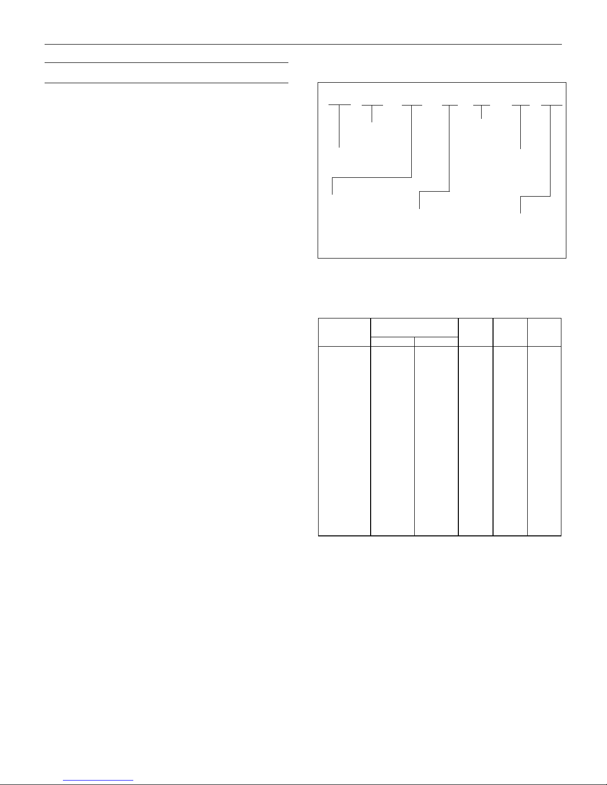
Interpreting Model Numbers
Full Automatic or Manual Mode
Sentry FR chargers are designed for fully automatic operation,
or for manual operation. In the automatic mode, the charger
will turn “off” when a full charge condition is “sensed.”
Circuit Breaker at Ship’s Panel
Activate the circuit breaker.
Charger indication: Light - Red.
Automatic/Manual Selector Switch
Set to “automatic.” This is the selection for the majority of
conditions.
Set to “Manual”:
(Recommended for short time frames only.)
• If an “extra” charge for starting the engine is needed.
Note: Leave in “Automatic” all other times.
To leave in “Manual” will:
• Overcharge the battery.
• Dehydrate the battery.
• Warp the plates in the battery.
Ammeter Indications
All batteries fully charged: Ammeter indication = 0.
Batteries not fully charged: Ammeter shows output in amperes.
FR 12 40 A / 3 X J
Output
DC Voltage
Ferro-Resonant
Series
Output DC
Amperage
Control Circuit Calibration
A: lead calcium batteries
No letter: lead acid batteries
Wiring Gauge & Grade Chart
Sentry AC DC AC
Model 0-10 Ft 10-25 Ft. Cir. Bkr. FuseFuse*
FR1220/3B 10 8 10A BAF305A
FR1240/3X 6 4 15A ANL50 10A
FR1240A/3X 6 4 15A ANL50 10A
FR1240/3XJ 6 4 15A ANL50 10A
FR1260/3X 6 2 15A ANL80 15A
FR1260/4X 6 2 15A ANL80 15A
FR1260A/3X 6 2 15A ANL80 15A
FR2425/3X10 815AANL3510A
FR2425A/3X10 8 15AANL35 10A
FR2440/3X 8 6 15A ANL50 15A
FR2440A/3X 8 6 15A ANL50 15A
FR2440/3XJ 8 6 15A ANL50 15A
FR2460/3XJ 6 2 20A ANL80 20A
FR2460/4XJ 6 2 20A ANL80 20A
FR3230/3X 8 6 20A ANL40 20A
Note: All wire insulation should be rated for 105 C.
* AC Fuses rated slow blow at 250VAC (fuses implemented on Dec 2004, Serial# 448*****
Wire Gauge
Sentry Unit to Batteries
Number of
Output Circuits
AC Input Voltage
B: 115 Volts
C: 230 Volts
X: 115/230 Volts
AC input Cycles
No letter: 60 Cycles
J: 50/60 Cycles
K: 50 Cycles Only
L-0921 Operation
5
English
❖❖
❖
❖❖

Troubleshooting
Warning
Only the following are recommended for an owner. All other
work should be done by an authorized Sentry service
representative.
Situation
Charger does not turn “off,” and the ammeter shows that
charger is active.
Solution
1. Automatic/Manual selector switch in “manual” position.
Switch to “automatic.”
Always “de-energize” by turning “off” the AC circuit breaker at
the ship’s main panel
to repair this charger.
If you have continued occurance of the same problem,
contact an authorized service representative or the Dometic
factory.
before removing the cover or attempting
System Troubleshooting
Situation
Will not charge in either manual or automatic position;
ammeter indicates “0” amps.
Solution
1. DC fuse has failed. Replace.
2. AC circuit breaker has failed. Reset. Consult circuit
breaker/fuse chart.
3. AC fuse has failed. Replace.
Situation
Charger turns “off” or “on” too early or too late.
Solution
1. Battery connections “loose” or “dirty.” Tighten, and/or
clean.
2. Control circuit - out of calibration. See calibration procedures.
2. Determine if battery connections are clean and tight.
3. Shorted cell in battery - replace battery.
4. Control circuit out of calibration - calibrate. See calibration
procedures.
Control Calibration Procedures
See chart below for voltages
1. Connect four (4) sensing wires (color - red) from the
control to a
battery is connected.
2. Determine the voltage between this terminal (see above)
and the “--- BATTERY” terminal. Use a digital voltmeter
accurate to .1 volt.
3. See table (below) to understand correct “pull-in” and “dropout” voltage.
4. FR type chargers - set “pull-in” first. Apply a small load
(interior light, etc). Note the “pull-in” voltage.
5. Locate “pull-in” potentiometer. If “pull-in” high - decrease turn clockwise.
If “pull-in” low - increase - turn counter-clockwise.
Allow the charger to raise the battery voltage; note “dropout” voltage.
Locate “drop-out” potentiometer.
If “drop-out” high - decrease differential - turn clockwise.
single “+BATTERY” tab terminal, to which a
Situation
Charger will not charge. Transformer is “active.”
Solution
1. Battery connections “loose” or “dirty.” Tighten, and/or
clean.
2. DC fuse has failed. Replace. Consult circuit breaker/fuse
chart.
Situation
Full charge light will not illuminate. Charger turns “on” and
“off” properly.
Solution
Lamp defective. Replace lamp.
L-0921 Troubleshooting
If “drop-out” low - increase - turn counter-clockwise.
Repeat procedure - until the correct voltage is obtained.
6. Replace the sensing wires (color - red).
Note: do not attach a red wire where there is no battery. If
extra wires, attach to a terminal with a battery (more than
one sensing wire is acceptable).
attached to a battery. See Figure 3.
12 Volt Chargers 12.8 13.9
24 Volt Chargers 25.5 28.0
32 Volt Chargers 34.5 37.5
6
All red wires must be
Pull In Drop Out
English
❖❖
❖
❖❖
 Loading...