

Page 1
ENDEFR
ESPTITNLDASVNOFIRUPLSKCSHU
WINDOWS & DOORS
BLINDS
Hor voor schuifdeuren
Montagehandleiding en
gebruiksaanwijzing. . . . . . . . . . . . . . . . . . . 58
Net til skydedøre
Monterings- og betjeningsvejledning. . . . 66
Insektsskydd för skjutdörrar
Monterings- och bruksanvisning . . . . . . . . 74
Insektsbeskyttelse for skyvedører
Monterings- og bruksanvisning. . . . . . . . . 81
FlyTec FT200
Flyscreen for sliding doors
Installation and Operating Manual. . . . . . . .8
Insektenschutz für Schiebetüren
Montage- und Bedienungsanleitung . . . . . 16
Moustiquaire pour portes
coulissantes
Instructions de montage
et de service . . . . . . . . . . . . . . . . . . . . . . . . .24
Protección contra insectos para
puertas corredizas
Instrucciones de montaje y de uso. . . . . . .33
Hyttyssuoja liukuoviin
Asennus- ja käyttöohje . . . . . . . . . . . . . . . . 88
Москитная сетка для сдвижных
дверей
Инструкция по монтажу и эксплуатации . 95
Ochrona przed insektami dla drzwi
przesuwnych
Instrukcja montażu i obsługi. . . . . . . . . . . 104
Protihmyzová sieťka pre posuvné
dvere
Návod na montáž a uvedenie
do prevádzky. . . . . . . . . . . . . . . . . . . . . . . 113
Síť proti hmyzu na posuvné dveře
Návod k montáži a obsluze . . . . . . . . . . . 121
Rovarvédő tolóajtókhoz
Szerelési és használati útmutató . . . . . . . 128
Proteção contra insetos para portas
deslizantes
Instruções de montagem e manual de
instruções . . . . . . . . . . . . . . . . . . . . . . . . . . . 41
Zanzariera per porte scorrevoli
Istruzioni di montaggio e d’uso . . . . . . . . .50
Page 2

Page 3
Dometic FlyTec FT200
3
5
4
1
8
2
6
7
1
C = 15 mm
A =
18 mm
B = 3 mm
5
4
3
2
≥ 20 mm
2
1
40 mm
X
Y
3
Page 4
Dometic FlyTec FT200
1.
4.
3.
2.
3
4
4
Page 5
Dometic FlyTec FT200
1.
2.
3.
5
6
2.
1.
7
5
Page 6
Dometic FlyTec FT200
7x
8
1
2
1.
3.
2.
4.
9
6
Page 7
Dometic FlyTec FT200
0
7
Page 8

EN
Explanation of symbols Dometic FlyTec FT200
Please read this instruction manual carefully before installation and first
use, and store it in a safe place. If you pass on the product to another
person, hand over this instruction manual along with it.
Contents
1 Explanation of symbols. . . . . . . . . . . . . . . . . . . . . . . . . . . . . . . . . . . . . . . . . . .8
2 Safety instructions . . . . . . . . . . . . . . . . . . . . . . . . . . . . . . . . . . . . . . . . . . . . . . .9
3 Scope of delivery . . . . . . . . . . . . . . . . . . . . . . . . . . . . . . . . . . . . . . . . . . . . . . .9
4 Intended use . . . . . . . . . . . . . . . . . . . . . . . . . . . . . . . . . . . . . . . . . . . . . . . . . .10
5 Installing the flyscreen. . . . . . . . . . . . . . . . . . . . . . . . . . . . . . . . . . . . . . . . . . .10
6 Using the flyscreen . . . . . . . . . . . . . . . . . . . . . . . . . . . . . . . . . . . . . . . . . . . . .14
7 Cleaning and maintenance. . . . . . . . . . . . . . . . . . . . . . . . . . . . . . . . . . . . . . .14
8 Warranty . . . . . . . . . . . . . . . . . . . . . . . . . . . . . . . . . . . . . . . . . . . . . . . . . . . . .14
9 Disposal . . . . . . . . . . . . . . . . . . . . . . . . . . . . . . . . . . . . . . . . . . . . . . . . . . . . . .15
10 Versions . . . . . . . . . . . . . . . . . . . . . . . . . . . . . . . . . . . . . . . . . . . . . . . . . . . . . .15
1 Explanation of symbols
NOTICE!
A
Failure to observe this instruction can cause material damage and impair
the function of the product.
NOTE
Supplementary information for operating the product.
I
8
Page 9

EN
Dometic FlyTec FT200 Safety instructions
2 Safety instructions
Please observe the safety instructions and stipulations issued by the vehicle
manufacturer and service workshops.
The manufacturer accepts no liability for damage in the following cases:
•
Faulty assembly or connection
•
Damage to the product resulting from mechanical influences
•
Alterations to the product without express permission from the manufacturer
•
Use for purposes other than those described in the operating manual
NOTICE!
•
A
If you do not have sufficient technical knowledge for installing
components in vehicles, you should have a specialist install the flyscreen in your vehicle.
•
Check whether the dimensions of the flyscreen fit your vehicle.
•
Installation of the flyscreen requires two people.
3Scope of delivery
No. in
fig. 1,
page 3
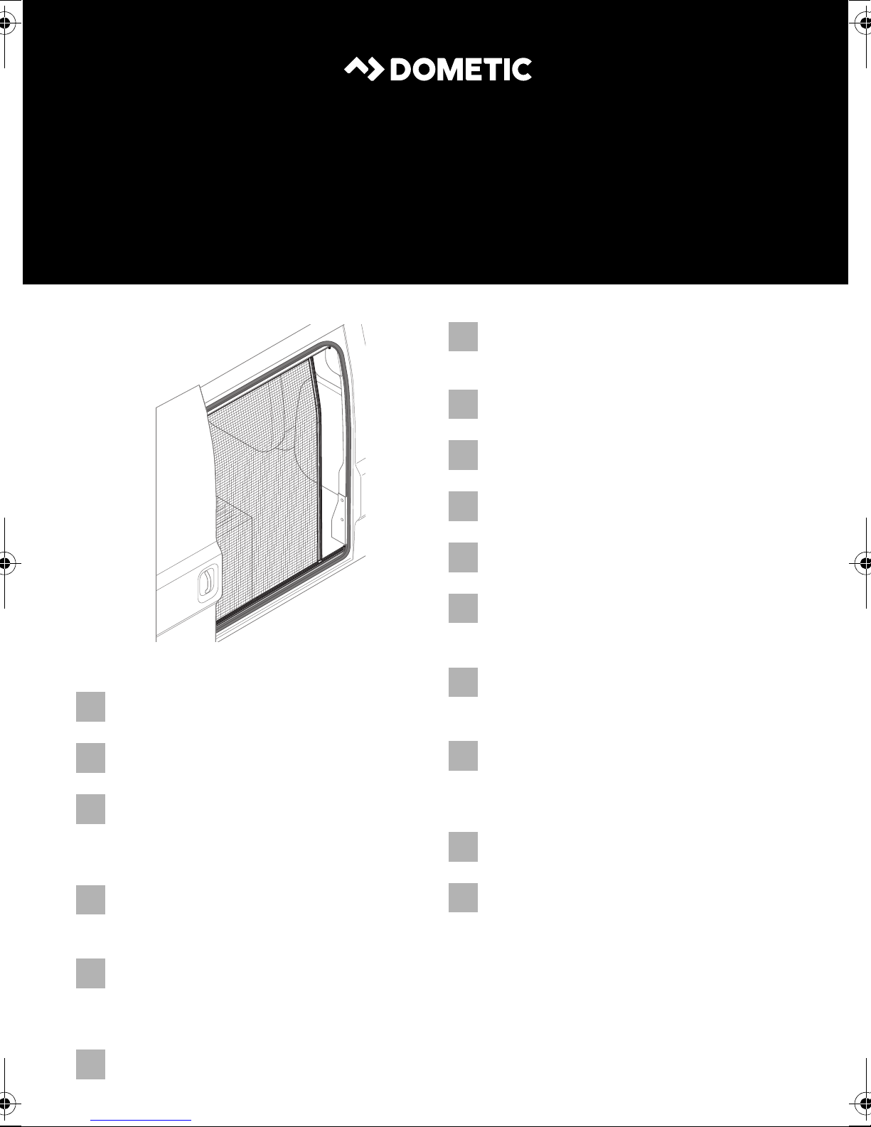
1 1 Skirting board
2 1 Cassette profile with flyscreen and guide cables
3 1 C pillar cover
4 7 Blind rivet (4 x 8 mm with stainless steel mandrel)
5 1 Fastening screw M5 x 30 mm and M5 nut
6 1 Guide rail above
7 1 Safety clip and screw M2.5 x 6
Quantity Description
8 1 Deflection screw M4 with safety clip and screw M2.5 x 6
– Installation and operating manual
The screws for fastening on the vehicle are not included in the scope of delivery.
9
Page 10

EN
Intended use Dometic FlyTec FT200
4 Intended use
The Dometic FlyTec FT200 is a flyscreen for sliding doors on camper vans which can
be slid or folded horizontally. For available versions see the table, page 15.
5 Installing the flyscreen
5.1 Notes on installation
•
Before installing the flyscreen, check whether any vehicle components could be
damaged by the installation of the flyscreen (such as cupboards).
•
For safety reasons, note the location of existing wiring harnesses, wires and other
components within the installation area, in particular those which are not visible,
when installing the flyscreen (when drilling or screwing, etc.).
5.2 Preparing the vehicle
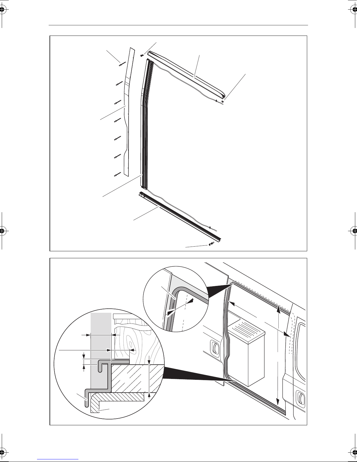
Measuring the opening (fig. 2, page 3)
Please observe the following instructions when measuring:
•
The installation opening should not have been made smaller through added
strips, coverings, fixtures, etc.
•
The installation opening must have the minimum width of X and minimum height
of Y:
FlyTec version (ref. no.) Minimum width X Minimum height Y
9104117297 and 9104117296 1298 mm 1765 mm
9104117387 and 9104117388 1128 mm 1492 mm
•
Behind the rear sealing of the door (1), there needs to be a minimum of 40 mm
space for the flyscreen to be installed.
•
There needs to be a space with a width of A = 18 mm between the outer edge of
the bodywork floor (4) and fitted cabinets (2) (e.g. kitchen).
10
Page 11

EN
Dometic FlyTec FT200 Installing the flyscreen
•
The skirting board (5) needs the following space:
– There needs to be a space with a width of A = 18 mm between the outer edge
of the bodywork floor (4) and the edge of the interior fittings base (3).
– A space with a height of B = 3 mm and a depth of C = 15 mm needs to be
available from the edge of the interior fittings base (3).
You may need to adapt fitted cabinets (2) and the interior fittings base (3).
•
The flyscreen must be screwed directly to the sheet-metal bodywork at the top
and not just on the panelling or the interior fittings. It is usually sufficient to screw
it on to the base of the interior fittings.
➤ Measure the installation opening in your vehicle and check whether the
dimensions of the flyscreen fit your vehicle.
Trimming the opening (depending on the vehicle)
➤ If necessary, remove add-on parts that interfere (such as bottom end strips or
bodywork) in the installation opening.
To be able to install the skirting board (fig. 1 1, page 3) flush, you may need to trim
the existing fixtures (such as floors or cabinets).
➤ Mark the following (fig. 2, page 3):
– Size A = 18 mm (width of the bottom part of the skirting board), measured
from the edge of the sheet-metal bodywork
– Size B = 3 mm (height of the skirting board).
➤ If necessary, trim the existing fixtures with a suitable tool, such as an oscillating
saw.
➤ Smooth and clean the cut edges.
11
Page 12

EN
Installing the flyscreen Dometic FlyTec FT200
5.3 Pre-installing the rails
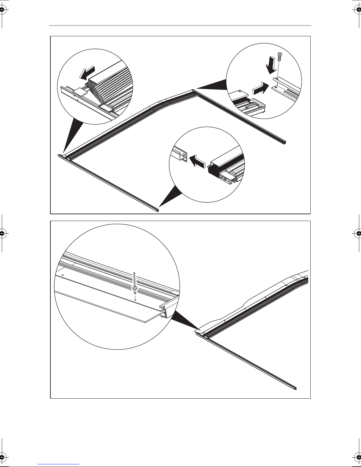
Cassette profile, skirting board and upper guide rail
The cassette profile, skirting board and upper guide rail must be assembled lying on
the ground (fig. 3, page 4) before being placed in the vehicle.
➤ Check whether the cover profile can be inserted between the C pillar and interior
fittings. You may need to adapt the contour by trimming.
➤ Guide the lower slider of the handle strip along with the cassette profile into the
skirting board.
➤ Pull the cassette and handle strip apart by a bit and then slide the cassette profile
onto the nose on the skirting board.
➤ Secure the cassette profile with the screw (M5 x 30 mm) and M5 nut on the upper
guide rail.
➤ Insert the cover for the C pillar into the cassette so that the drill holes are located
one above the other and secure the two components with three blind rivets
(4 x 8 mm with stainless steel mandrel) without riveting them (fig. 4, page 4).
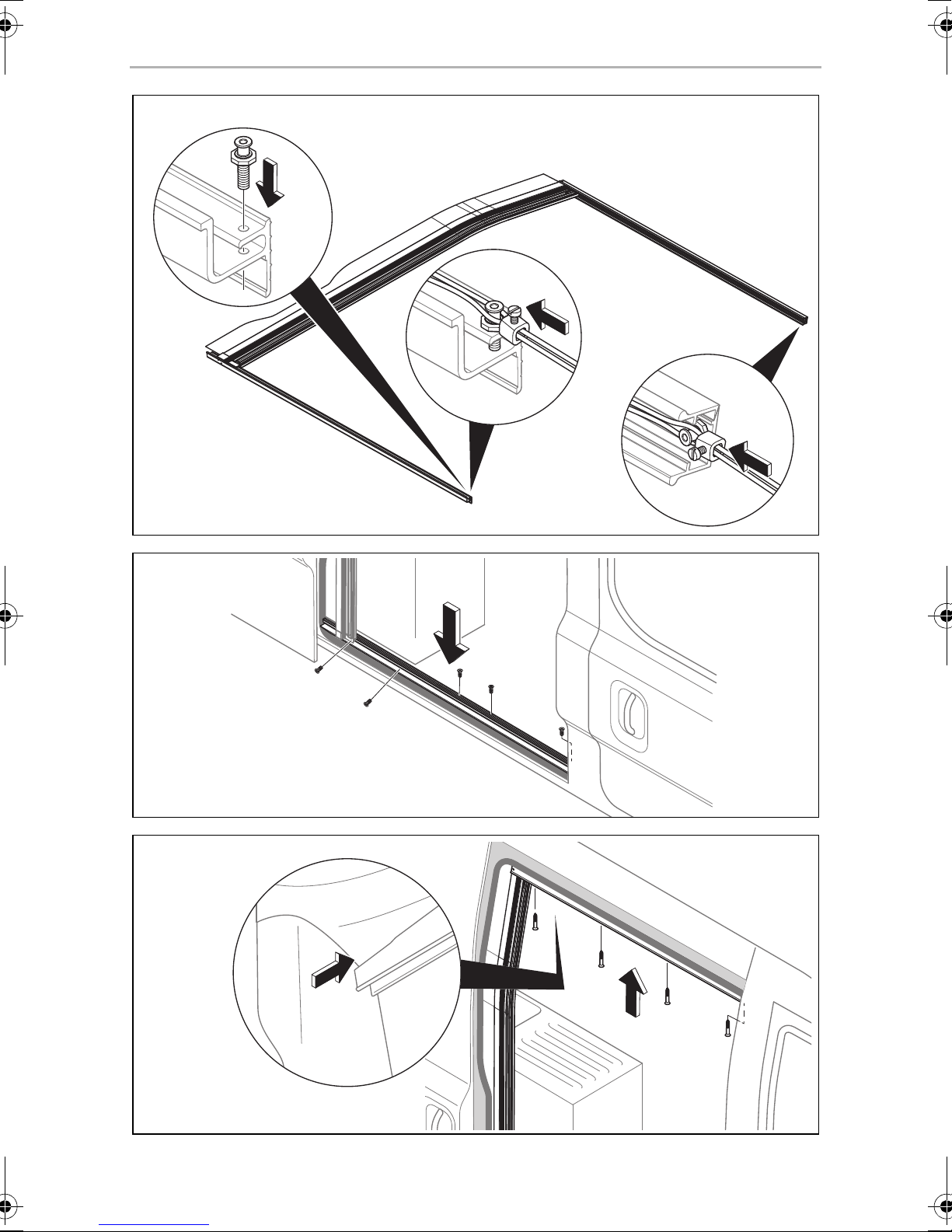
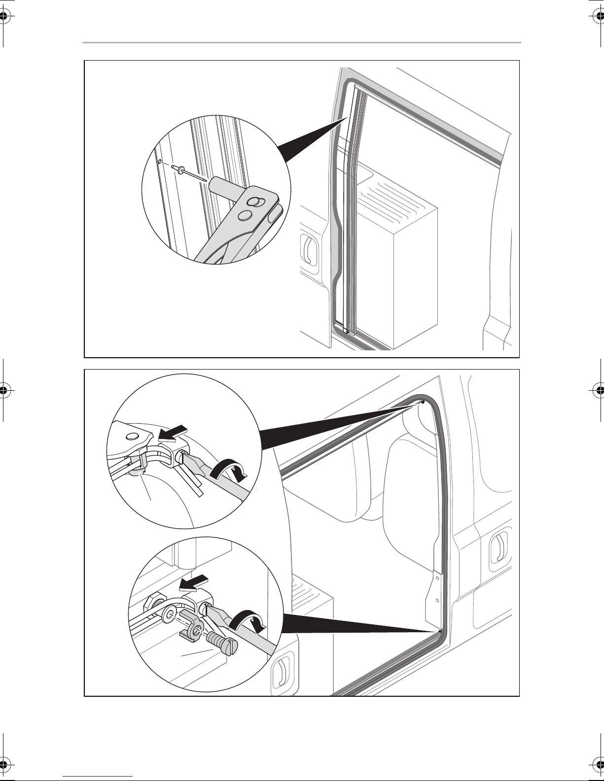
➤ Secure the deflection screw M4 (fig. 5 1, page 5) to the skirting board.
➤ Fit the guide cables into the bottom and top deflection screw (fig. 5 2 and 3,
page 5).
NOTICE! Risk of breaking the lower plastic slider
A
➤ Have two people carefully lift the pre-assembled flyscreen and position it in the
vehicle.
Adjusting the top guide rail
➤ Check whether the contour and position of the upper guide rail fit the vehicle
(see enlarged inset in fig. 7, page 5). You may need to adjust the upper guide
rail by cutting the two upper legs.
Be careful when you are lifting and positioning the flyscreen and do not
bend or tilt the skirting board.
12
Page 13

EN
Dometic FlyTec FT200 Installing the flyscreen
5.4 Securing the flyscreen in the vehicle
NOTICE!
•
A
Securing the skirting board and upper guide rail
➤ Align the position of the cassette profile perpendicular to the skirting board and
the upper guide rail.
➤ Secure the skirting board to the bottom plate (fig. 6, page 5) with five counter-
sunk screws (Ø 4 mm).
➤ Secure the upper guide rail to the vehicle (fig. 7, page 5) with four countersunk
screws (Ø 4 mm).
Choose suitable screws depending on the floor and roof
construction.
•
Make sure that you do not drill through the floor and roof.
5.5 Completing installation
Riveting the cassette profile with the cover profile for the C pillar (fig. 8,
page 6)
➤ Put all the blind rivets (4 x 8 mm with stainless steel mandrel) through the drill
holes and rivet the components using a hand riveter.
Tensioning the guide cables
➤ Tension the guide cables on the deflection screws on the skirting board and the
top guide rail (fig. 9, page 6).
The tension of the cables affects the guidance and smooth running of the handle
strip. By changing the tension of the upper and lower cable, you can adjust the
parallel orientation of the handle strip to the right door edge.
➤ Secure the safety clips onto the deflection screws each with a screw
(M2.5 x 6 mm) (fig. 9 1 and 2, page 6).
13
Page 14

EN
Using the flyscreen Dometic FlyTec FT200
6 Using the flyscreen
NOTICE! Beware of damage!
A
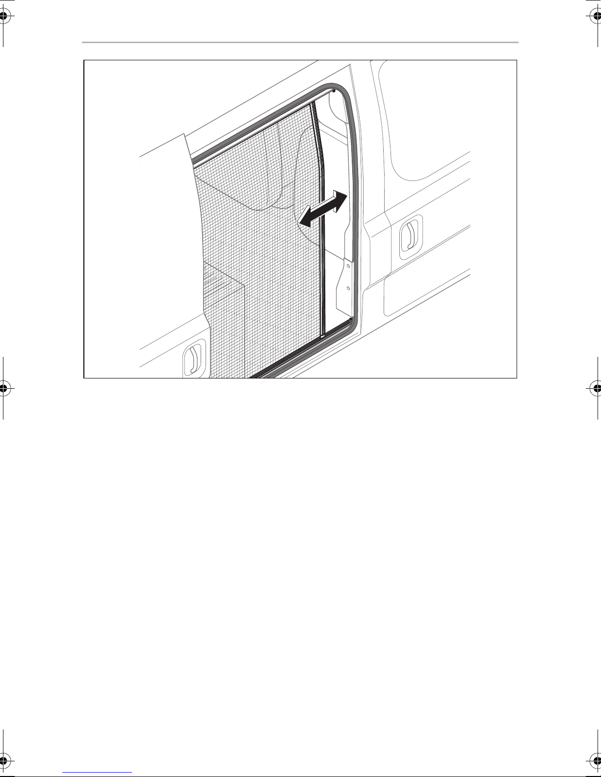
Closing the flyscreen
➤ Pull the handle strip on the flyscreen to close the flyscreen (fig. 0, page 7).
Opening the flyscreen
➤ Pull the handle strip on the flyscreen to open the flyscreen (fig. 0, page 7).
The sliding door of the vehicle may be closed only when the flyscreen is
fully open.
7 Cleaning and maintenance
NOTICE!
A
➤ Occasionally clean the product with a damp cloth.
➤ Spray the guide rails on the sliding surfaces periodically with small amounts of
silicone spray to achieve the easiest possible sliding of the cassette profile in the
guide rails.
Do not use sharp or hard objects or cleaning agents for cleaning as these
may damage the product.
8Warranty
The statutory warranty period applies. If the product is defective, please contact the
service partner in your country (addresses on the back on the instruction manual).
Our experts will be happy to help you and will discuss the warranty process with you
in more detail.
14
Page 15

EN
Dometic FlyTec FT200 Disposal
9Disposal
➤ Place the packaging material in the appropriate recycling waste bins wherever
possible.
If you wish to finally dispose of the product, ask your local recycling centre
or specialist dealer for details about how to do this in accordance with the
M
applicable disposal regulations.
10 Versions
Version Dimensions Ref. no.
Version in direction of travel on the right for Fiat
Ducato, Citroën Jumper, Peugeot Boxer from model
year 2006, higher version
Version in direction of travel on the left for Fiat
Ducato, Citroën Jumper, Peugeot Boxer from model
year 2006, higher version
Version in direction of travel on the right for Fiat
Ducato, Citroën Jumper, Peugeot Boxer from model
year 2006, lower version
Version in direction of travel on the left for Fiat
Ducato, Citroën Jumper, Peugeot Boxer from model
year 2006, lower version
1298 x 1765 mm 9104117297
1298 x 1765 mm 9104117296
1128 x 1492 mm 9104117387
1128 x 1492 mm 9104117388
15
Page 16

DE
Erklärung der Symbole Dometic FlyTec FT200
Bitte lesen Sie diese Anleitung vor Einbau und Inbetriebnahme sorgfältig
durch und bewahren Sie sie auf. Geben Sie sie im Falle einer Weitergabe
des Produktes an den Nutzer weiter.
Inhalt
1 Erklärung der Symbole . . . . . . . . . . . . . . . . . . . . . . . . . . . . . . . . . . . . . . . . . .16
2 Sicherheitshinweise . . . . . . . . . . . . . . . . . . . . . . . . . . . . . . . . . . . . . . . . . . . .17
3 Lieferumfang . . . . . . . . . . . . . . . . . . . . . . . . . . . . . . . . . . . . . . . . . . . . . . . . . .17
4 Bestimmungsgemäßer Gebrauch . . . . . . . . . . . . . . . . . . . . . . . . . . . . . . . . .18
5 Insektenschutz montieren. . . . . . . . . . . . . . . . . . . . . . . . . . . . . . . . . . . . . . . .18
6 Insektenschutz benutzen . . . . . . . . . . . . . . . . . . . . . . . . . . . . . . . . . . . . . . . .21
7 Reinigung und Pflege . . . . . . . . . . . . . . . . . . . . . . . . . . . . . . . . . . . . . . . . . . 22
8 Gewährleistung. . . . . . . . . . . . . . . . . . . . . . . . . . . . . . . . . . . . . . . . . . . . . . . 22
9 Entsorgung . . . . . . . . . . . . . . . . . . . . . . . . . . . . . . . . . . . . . . . . . . . . . . . . . . 22
10 Versionen. . . . . . . . . . . . . . . . . . . . . . . . . . . . . . . . . . . . . . . . . . . . . . . . . . . . 23
1 Erklärung der Symbole
ACHTUNG!
A
Nichtbeachtung kann zu Materialschäden führen und die Funktion des
Produktes beeinträchtigen.
HINWEIS
Ergänzende Informationen zur Bedienung des Produktes.
I
16
Page 17

DE
Dometic FlyTec FT200 Sicherheitshinweise
2 Sicherheitshinweise
Beachten Sie die vom Fahrzeughersteller und vom Kfz-Handwerk vorgeschriebenen
Sicherheitshinweise und Auflagen!
Der Hersteller übernimmt in folgenden Fällen keine Haftung für Schäden:
•
Montage- oder Anschlussfehler
•
Beschädigungen am Produkt durch mechanische Einflüsse
•
Veränderungen am Produkt ohne ausdrückliche Genehmigung vom Hersteller
•
Verwendung für andere als die in der Anleitung beschriebenen Zwecke
ACHTUNG!
•
A
Wenn Sie nicht über ausreichende technische Kenntnisse zum Einbauen von Komponenten in Fahrzeugen verfügen, sollten Sie sich den
Insektenschutz von einem Fachmann ins Fahrzeug einbauen lassen.
•
Prüfen Sie, ob die Abmessungen des Insektenschutzes zu Ihrem
Fahrzeug passen.
•
Die Montage des Insektenschutzes erfordert zwei Personen.
3 Lieferumfang
Pos. in
Abb. 1, Seite 3
1 1 Trittleiste
2 1 Kassettenprofil mit Fliegengaze und Führungsseilen
3 1 Abdeckprofil C-Säule
4 7 Blindniete (4 x 8 mm mit VA-Dorn)
5 1 Befestigungsschraube M5 x 30 mm und Mutter M5
6 1 Führungsschiene oben
7 1 Sicherungsbügel und Schraube M2,5 x 6
8 1 Umlenkschraube M4 mit Sicherungsbügel und
Anzahl Beschreibung
Schraube M2,5 x 6
– Montage- und Bedienungsanleitung
Die Schrauben für die fahrzeugseitige Befestigung sind nicht im Lieferumfang
enthalten.
17
Page 18

DE
Bestimmungsgemäßer Gebrauch Dometic FlyTec FT200
4 Bestimmungsgemäßer Gebrauch
Dometic FlyTec FT200 ist ein horizontal verschiebbarer, faltbarer Insektenschutz für
Schiebetüren von Campingbussen. Verfügbare Versionen siehe Tabelle, Seite 23.
5 Insektenschutz montieren
5.1 Hinweise zur Montage
•
Prüfen Sie vor Montage des Insektenschutzes, ob durch den Einbau ggf.
Fahrzeugkomponenten beschädigt werden könnten (z. B. Schränke).
•
Achten Sie aus Sicherheitsgründen beim Einbau des Insektenschutzes (beim
Bohren und Schrauben usw.) auf den Verlauf von vorhandenen, insbesondere
nicht sichtbaren Kabelsträngen, Leitungen und anderen Komponenten, die sich
im Montagebereich befinden.
5.2 Vorbereitung des Fahrzeuges
Öffnung ausmessen (Abb. 2, Seite 3)
Beachten Sie folgende Hinweise zum Ausmessen:
•
Die Einbauöffnung darf nicht durch angebaute Leisten, Abdeckungen,
Einbauten o. ä. verkleinert sein.
•
Die Einbauöffnung muss folgende Mindestbreite X und Mindesthöhe Y aufweisen:
FlyTec-Version (Art.-Nr.) Mindestbreite X Mindesthöhe Y
9104117297 und 9104117296 1298 mm 1765 mm
9104117387 und 9104117388 1128 mm 1492 mm
•
Hinter der hinteren Dichtung der Tür (1) muss mindestens 40 mm Raum für den
Einbau des Insektenschutzes verfügbar sein.
•
Zwischen der Außenkante des Karosseriebodens (4) und Einbauschränken (2)
(z. B. Küche) muss ein Freiraum mit einer Breite von A = 18 mm verfügbar sein.
18
Page 19

DE
Dometic FlyTec FT200 Insektenschutz montieren
•
Für die Trittleiste (5) müssen folgende Freiräume verfügbar sein:
– Zwischen der Außenkante des Karosseriebodens (4) und der Kante des
Innenausbaubodens (3) muss ein Freiraum mit einer Breite von A = 18 mm
verfügbar sein.
– Ab der Kante des Innenausbaubodens (3) muss in einer Höhe von B = 3 mm
ein Freiraum mit einer Tiefe von C = 15 mm verfügbar sein.
Eventuell müssen Einbauschränke (2) und der Innenausbauboden (3) angepasst
werden.
•
Der Insektenschutz muss oben direkt mit dem Karosserieblech verschraubt
werden, nicht nur an der Verkleidung oder dem Innenausbau. Unten ist die
Verschraubung in den Innenausbauboden normalerweise ausreichend.
➤ Messen Sie die Einbauöffnung in Ihrem Fahrzeug aus und prüfen Sie, ob die
Abmessungen des Insektenschutzes an Ihr Fahrzeug passen.
Öffnung beschneiden (abhängig vom Fahrzeug)
➤ Demontieren Sie ggf. störende Anbauteile (z. B. Bodenabschlussleisten oder
Verkleidungen) in der Einbauöffnung.
Um die Trittleiste (Abb. 1 1, Seite 3) bündig montieren zu können, müssen
eventuell vorhandene Einbauten (z. B. die Böden oder Einbauschränke) beschnitten
werden.
➤ Zeichnen Sie wie folgt an (Abb. 2, Seite 3):
– Maß A = 18 mm (Breite des unteren Schenkels der Trittleiste), gemessen von
der Kante des Karosserieblechs
– Maß B = 3 mm (Höhe der Trittleiste).
➤ Beschneiden Sie, falls erforderlich, vorhandene Einbauten mit geeignetem
Werkzeug, z. B. mit einer Schwingsäge.
➤ Glätten und säubern Sie die Schnittkanten.
5.3 Schienen vormontieren
Kassettenprofil, Trittleiste und obere Führungsschiene
Kassettenprofil, Trittleiste und obere Führungsschiene müssen am Boden liegend
vormontiert werden (Abb. 3, Seite 4), bevor sie im Fahrzeug platziert werden.
➤ Prüfen Sie, ob das Abdeckprofil zwischen C-Säule und Innenausbau eingescho-
ben werden kann. Ggf. müssen Sie die Kontur durch Beschneiden anpassen.
➤ Führen Sie den unteren Gleiter der Griffleiste zusammen mit dem Kassettenprofil
in die Trittleiste ein.
19
Page 20

DE
Insektenschutz montieren Dometic FlyTec FT200
➤ Ziehen Sie die Kassette und die Griffleiste etwas auseinander und schieben Sie
dann das Kassettenprofil auf die Nase an der Trittleiste.
➤ Befestigen Sie das Kassettenprofil mit der Schraube (M5 x 30 mm) und Mutter
M5 an der obere Führungsschiene.
➤ Stecken Sie das Abdeckprofil für die C-Säule in die Kassette, so dass sich die
Bohrlöcher übereinander befinden und fixieren Sie beiden Bauteile mit drei
Blindnieten (4 x 8 mm mit VA-Dorn), ohne diese zu vernieten (Abb. 4, Seite 4).
➤ Schrauben Sie die Umlenkschraube M4 (Abb. 5 1., Seite 5) in die Trittleiste.
➤ Hängen Sie die Führungsseile in die untere und in die obere Umlenkschraube ein
(Abb. 5 2. und 3., Seite 5).
ACHTUNG! Bruchgefahr des unteren Kunststoffgleiters
A
Seien Sie beim Anheben und Positionieren des Insektenschutzes im
Fahrzeug vorsichtig und biegen oder verkanten Sie die Trittleiste nicht.
➤ Heben Sie den vormontierten Insektenschutz zu zweit vorsichtig auf und
positionieren Sie ihn im Fahrzeug.
Obere Führungsschiene anpassen
➤ Prüfen Sie, ob die Kontur und die Lage der oberen Führungsschiene zum
Fahrzeug passt (siehe Lupe in Abb. 7, Seite 5). Ggf. müssen Sie die obere
Führungsschiene durch Beschneiden der beiden oberen Schenkel anpassen.
5.4 Insektenschutz im Fahrzeug befestigen
ACHTUNG!
•
A
Trittleiste und obere Führungsschiene befestigen
➤ Richten Sie die Lage des Kassettenprofils rechtwinklig zur Trittleiste und zur
oberen Führungsschiene aus.
Wählen Sie abhängig von der Boden- und Dachkonstruktion
geeignete Schrauben aus.
•
Achten Sie darauf, dass Sie Boden und Dach nicht durchbohren.
➤ Befestigen Sie die Trittleiste mit fünf Senkkopfschrauben (Ø4 mm) auf der
Bodenplatte (Abb. 6, Seite 5).
➤ Befestigen Sie die obere Führungsschiene mit vier Senkkopfschrauben (Ø4 mm)
am Fahrzeug (Abb. 7, Seite 5).
20
Page 21

DE
Dometic FlyTec FT200 Insektenschutz benutzen
5.5 Montage abschließen
Kassettenprofil mit dem Abdeckprofil für die C-Säule vernieten (Abb. 8,
Seite 6)
➤ Stecken Sie alle Blindniete (4 x 8 mm mit VA-Dorn) durch die Bohrlöcher und ver-
nieten Sie die Bauteile mit Hilfe einer Blindnietzange miteinander.
Führungsseile nachspannen
➤ Spannen Sie die Führungsseile an den Umlenkschrauben an der Trittleiste und an
der oberen Führungsschiene (Abb. 9, Seite 6) nach.
Die Spannung der Seile beeinflusst die Führung und Leichtgängigkeit der Griffleiste.
Durch unterschiedliche Spannung der oberen und unteren Seile kann die parallele
Ausrichtung der Griffleiste zur rechten Türkante justiert werden.
➤ Fixieren Sie die Sicherungsbügel auf den Umlenkschrauben jeweils mit einer
Schraube (M2,5 x 6 mm) (Abb. 9 1 und 2, Seite 6).
6 Insektenschutz benutzen
ACHTUNG! Beschädigungsgefahr!
A
Insektenschutz schließen
➤ Ziehen Sie den Insektenschutz an der Griffleiste zu, um den Insektenschutz zu
schließen (Abb. 0, Seite 7).
Insektenschutz öffnen
➤ Ziehen Sie den Insektenschutz an der Griffleiste auf, um den Insektenschutz zu
öffnen (Abb. 0, Seite 7).
Die Schiebetür des Fahrzeugs darf nur bei vollständig geöffnetem
Insektenschutz geschlossen werden.
21
Page 22

DE
Reinigung und Pflege Dometic FlyTec FT200
7 Reinigung und Pflege
ACHTUNG!
A
➤ Reinigen Sie das Produkt gelegentlich mit einem feuchten Tuch.
➤ Sprühen Sie die Führungsschienen an den Gleitflächen in regelmäßigen
Abständen mit Silikonspray in geringer Dosis ein, um ein möglichst leichtes
Gleiten des Kassettenprofils in den Führungsschienen zu erreichen.
Keine scharfen oder harten Gegenstände oder Reinigungsmittel zur
Reinigung verwenden, da dies zu einer Beschädigung des Produktes
führen kann.
8Gewährleistung
Es gilt die gesetzliche Gewährleistungsfrist. Sollte das Produkt defekt sein, wenden
Sie sich bitte an einen Service-Partner in Ihrem Land (Adressen siehe Rückseite der
Anleitung).
Unsere Spezialisten helfen Ihnen gerne weiter und besprechen mit Ihnen den
weiteren Verlauf der Gewährleistung.
9Entsorgung
➤ Geben Sie das Verpackungsmaterial möglichst in den entsprechenden
Recycling-Müll.
Wenn Sie das Produkt endgültig außer Betrieb nehmen, informieren Sie
sich bitte beim nächsten Recyclingcenter oder bei Ihrem Fachhändler
M
über die zutreffenden Entsorgungsvorschriften.
22
Page 23

DE
Dometic FlyTec FT200 Versionen
10 Versionen
Version Einbaumaße Art.-Nr.
Version in Fahrtrichtung rechts für Fiat Ducato,
Citroën Jumper, Peugeot Boxer ab Modelljahr
2006, hohe Version
Version in Fahrtrichtung links für Fiat Ducato,
Citroën Jumper, Peugeot Boxer ab Modelljahr
2006, hohe Version
Version in Fahrtrichtung rechts für Fiat Ducato,
Citroën Jumper, Peugeot Boxer ab Modelljahr
2006, niedrige Version
Version in Fahrtrichtung links für Fiat Ducato,
Citroën Jumper, Peugeot Boxer ab Modelljahr
2006, niedrige Version
1298 x 1765 mm 9104117297
1298 x 1765 mm 9104117296
1128 x 1492 mm 9104117387
1128 x 1492 mm 9104117388
23
Page 24

FR
Explication des symboles Dometic FlyTec FT200
Veuillez lire attentivement cette notice avant le montage et la mise en
service. Veuillez ensuite la conserver. En cas de passer le produit, veuillez
le transmettre au nouvel acquéreur.
Sommaire
1 Explication des symboles . . . . . . . . . . . . . . . . . . . . . . . . . . . . . . . . . . . . . . . 24
2 Consignes de sécurité . . . . . . . . . . . . . . . . . . . . . . . . . . . . . . . . . . . . . . . . . 25
3 Contenu de la livraison . . . . . . . . . . . . . . . . . . . . . . . . . . . . . . . . . . . . . . . . . 26
4 Usage conforme . . . . . . . . . . . . . . . . . . . . . . . . . . . . . . . . . . . . . . . . . . . . . . 26
5 Montage de la moustiquaire . . . . . . . . . . . . . . . . . . . . . . . . . . . . . . . . . . . . 27
6 Utilisation de la moustiquaire . . . . . . . . . . . . . . . . . . . . . . . . . . . . . . . . . . . . .31
7 Entretien et nettoyage . . . . . . . . . . . . . . . . . . . . . . . . . . . . . . . . . . . . . . . . . .31
8 Garantie. . . . . . . . . . . . . . . . . . . . . . . . . . . . . . . . . . . . . . . . . . . . . . . . . . . . . .31
9 Élimination. . . . . . . . . . . . . . . . . . . . . . . . . . . . . . . . . . . . . . . . . . . . . . . . . . . 32
10 Versions . . . . . . . . . . . . . . . . . . . . . . . . . . . . . . . . . . . . . . . . . . . . . . . . . . . . . 32
1 Explication des symboles
AVIS !
A
Le non-respect de ces consignes peut entraîner des dommages
matériels et des dysfonctionnements du produit.
REMARQUE
Informations complémentaires sur l'utilisation du produit.
I
24
Page 25

FR
Dometic FlyTec FT200 Consignes de sécurité
2 Consignes de sécurité
Respectez les consignes de sécurité et autres prescriptions imposées par le fabricant
du véhicule et par les professionnels de l’automobile !
Le fabricant décline toute responsabilité pour des dommages dans les cas suivants :
•
des défauts de montage ou de raccordement
•
des influences mécaniques ayant endommagé le matériel
•
des modifications apportées au produit sans autorisation explicite de la part du
fabricant
•
une utilisation différente de celle décrite dans la notice
AVIS !
•
A
Si vos connaissances techniques en matière d'installation d'éléments
dans un véhicule sont insuffisantes, nous vous recommandons de faire
installer la moustiquaire par un spécialiste.
•
Vérifiez si les dimensions de la moustiquaire sont adaptées à votre
véhicule.
•
Le montage de la moustiquaire exige deux personnes.
25
Page 26

FR
Contenu de la livraison Dometic FlyTec FT200
3 Contenu de la livraison
Pos. dans
fig. 1,
page 3
1 1 plinthe
2 1 cassette profilée avec gaze moustiquaire et cordons de
3 1 profilé couvrant la colonne C
4 7 rivetages aveugles (4 x 8 mm avec tige en aluminium)
5 1 vis de fixation M5 x 30 mm et écrou M5
6 1 rail de guidage en haut
7 1 étrier de sécurité et vis M2,5 x 6
Nombre Description
guidage
8 1 vis de renvoi M4 avec étrier de sécurité et vis M2,5 x 6
– notice de montage et d'utilisation
Les vis pour la fixation dans le véhicule ne sont pas fournies.
4Usage conforme
Dometic FlyTec FT200 est une moustiquaire pliable, coulissant à l'horizontale pour
les portes coulissantes de bus de camping. Pour les versions disponibles, voir le
tableau, page 32.
26
Page 27

FR
Dometic FlyTec FT200 Montage de la moustiquaire
5Montage de la moustiquaire
5.1 Consignes de sécurité concernant le montage
•
Avant le montage, vérifiez si des éléments du véhicule (p. ex. des armoires) ne
risquent pas d'être endommagés par la pose de la moustiquaire.
•
Pour des raisons de sécurité, faites attention lors de l’installation de la moustiquaire (opérations de perçage, de vissage, etc.) à la position des faisceaux de
câbles, conduites et autres éléments, éventuellement encastrés et invisibles, qui
se trouvent dans la zone de montage !
5.2 Préparation du véhicule
Mesure de l'ouverture (fig. 2, page 3)
Veuillez respecter les remarques suivantes sur les mesures :
•
l'ouverture d'encastrement ne doit pas être rétrécie par des barrettes, caches,
constructions, etc.
•
L'ouverture d'encastrement doit présenter la largeur minimale X et la hauteur
minimale Y suivantes :
Version FlyTec (n° art.) Largeur minimale X Hauteur minimale Y
9104117297 et 9104117296 1 298 mm 1 765 mm
9104117387 et 9104117388 1 128 mm 1 492 mm
•
40 mm au moins doivent être disponibles derrière le joint arrière de la porte (1)
pour le montage de la moustiquaire.
•
Entre le bord extérieur du plancher de la carrosserie (4) et des armoires
d'encastrement (2) (p. ex. cuisine), un espace libre d'une largeur A = 18 mm
doit être disponible.
•
Les espaces libres suivants doivent être disponibles pour la plinthe (5):
– Entre le bord extérieur du plancher de la carrosserie (4) et le bord du plancher
intérieur (3), un espace libre d'une largeur A = 18 mm doit être disponible.
– À partir du bord du plancher intérieur (3), à une hauteur de B = 3 mm, un
espace libre d'une profondeur de C = 15 mm doit être disponible.
Il faut éventuellement adapter des armoires encastrées (2) et le plancher
intérieur (3).
27
Page 28

FR
Montage de la moustiquaire Dometic FlyTec FT200
•
La moustiquaire doit être vissée directement à la tôle de la carrosserie en haut, et
pas seulement au revêtement ou à l'aménagement intérieur. En bas, le vissage
dans le plancher intérieur est normalement suffisant.
➤ Mesurez l'ouverture d'encastrement dans votre véhicule et vérifiez si les
dimensions de la moustiquaire sont adaptées à votre véhicule.
Découpage de l'ouverture (selon le véhicule)
➤ Le cas échéant, démontez les pièces rajoutées (p. ex. baguettes au sol ou habil-
lages) dans l'ouverture d'encastrement.
Pour pouvoir monter la plinthe (fig. 1 1, page 3) au même niveau que le cadre, les
constructions éventuellement rajoutées (p. ex. des étagères ou armoires encastrées)
doivent être découpées.
➤ Faites les marques suivantes (fig. 2, page 3) :
– Dimension A = 18 mm (largeur du côté inférieur de la plinthe), mesuré à partir
du bord de la tôle de la carrosserie
– Dimension B = 3 mm (hauteur de la plinthe).
➤ Découpez, si nécessaire, les constructions présentes avec un outil adapté, p. ex.
avec une scie pendulaire.
➤ Limez les arêtes de découpe afin qu'elles soient bien nettes.
28
Page 29

FR
Dometic FlyTec FT200 Montage de la moustiquaire
5.3 Prémontage des rails
Cassette profilée, plinthe et rail de guidage supérieur
La cassette profilée, la plinthe et le rail de guidage supérieur doivent être prémontés
à plat sur le sol (fig. 3, page 4) avant d'être montés dans le véhicule.
➤ Vérifiez si le profilé couvrant peut être glissé entre la colonne C et l'habillage inté-
rieur. Le cas échéant, vous devez découper le contour.
➤ Faites passer la glissière inférieure de la poignée avec la cassette profilé dans la
plinthe.
➤ Tirez sur la cassette et la poignée pour les écarter un peu et faites ensuite glisser
la cassette profilée sur le rebord au niveau de la plinthe.
➤ Fixez la cassette profilée avec la vis (M5 x 30 mm) et l'écrou M5 sur le rail de gui-
dage supérieur.
➤ Enfichez le profilé couvrant pour la colonne C dans la cassette, de sorte que les
trous de perçage se trouvent l'un au-dessus de l'autre et fixez les deux pièces
avec trois rivets aveugles (4 x 8 mm avec tige en aluminium) sans les riveter
(fig. 4, page 4).
➤ Vissez la vis de renvoi M4 (fig. 5 1., page 5) dans la plinthe.
➤ Accrochez les cordons de guidage dans les vis de renvoi du bas et du haut
(fig. 5 2. et 3., page 5).
AVIS ! Risque de rupture de la glissière inférieure en plastique
A
➤ Soulevez à deux et avec précaution la moustiquaire prémontée et positionnez-la
dans le véhicule.
Adaptation du rail de guidage supérieur
➤ Vérifiez si le contour et la position du rail de guidage supérieur sont adaptés au
véhicule (voir la loupe dans fig. 7, page 5). Le cas échéant, vous devez adapter
le rail de guidage supérieur en coupant les deux côtés supérieurs.
Soyez prudent lorsque vous soulevez et positionnez la moustiquaire
dans le véhicule et ne pliez pas ou ne tordez pas la barre.
29
Page 30

FR
Montage de la moustiquaire Dometic FlyTec FT200
5.4 Fixation de la moustiquaire dans le véhicule
AVIS !
•
A
Fixation de la plinthe et du rail de guidage supérieur
➤ Positionnez la cassette profilée à angle droit par rapport à la plinthe et au rail de
guidage supérieur.
➤ Fixez la plinthe avec cinq vis à tête fraisée (Ø4 mm) sur la plaque du sol (fig. 6,
page 5).
➤ Fixez le rail de guidage supérieur avec quatre vis à tête fraisée (Ø4 mm) au
véhicule (fig. 7, page 5).
En fonction de la construction du sol et du toit, choisissez des vis
adaptées.
•
Veillez à ne pas perforer le sol ni le toit.
5.5 Finition du montage
Rivetage de la cassette profilée avec le profilé couvrant pour la colonne C
(fig. 8, page 6)
➤ Enfichez tous les rivets aveugles (4 x 8 mm avec tige en aluminium) dans les trous
de perçage et assemblez les pièces par rivetage à l'aide d'une pince à rivets
aveugles.
Tension des cordons de guidage
➤ Retendez les cordons de guidage au niveau des vis de renvoi de la plinthe et du
rail de guidage supérieur (fig. 9, page 6).
La tension des cordons influence le guidage et la maniabilité de la poignée. La différence de tension entre le cordon du haut et celui du bas permet d'ajuster l'orientation parallèle de la poignée par rapport au bord droit de la porte.
➤ Fixez l'étrier de sécurité sur les vis de renvoi avec une vis (M2,5 x 6 mm) à chaque
fois (fig. 9 1 et 2, page 6).
30
Page 31

FR
Dometic FlyTec FT200 Utilisation de la moustiquaire
6 Utilisation de la moustiquaire
AVIS ! Risques d'endommagement !
A
Fermeture de la moustiquaire
➤ Fermez la moustiquaire en tirant sur la barre (fig. 0, page 7).
Ouverture de la moustiquaire
➤ Ouvrez la moustiquaire en tirant sur la barre (fig. 0, page 7).
La porte coulissante du véhicule ne doit être fermée que si la
moustiquaire est complètement ouverte.
7 Entretien et nettoyage
AVIS !
A
➤ Nettoyez le produit avec un tissu humide.
➤ Vaporisez à intervalles réguliers une faible dose de spray au silicone sur les sur-
faces de glissement des rails de guidage, afin que la cassette profilée glisse aussi
facilement que possible dans les rails de guidage.
N’utilisez aucun objet coupant ou dur, ni de détergents pour le
nettoyage. Cela pourrait endommager le produit.
8 Garantie
Le délai légal de garantie s'applique. Si le produit s'avérait défectueux, veuillez vous
adresser à un de nos partenaires de service présent dans votre pays (voir adresses au
dos du présent manuel).
Nos spécialistes vous aideront avec plaisir et répondront à vos questions concernant
la suite de la procédure pour la garantie.
31
Page 32

FR
Élimination Dometic FlyTec FT200
9Élimination
➤ Jetez les emballages dans les conteneurs de déchets recyclables prévus à cet
effet.
Lorsque vous mettrez votre produit définitivement hors service, informezvous auprès du centre de recyclage le plus proche ou auprès de votre
M
revendeur spécialisé sur les prescriptions relatives au retraitement des
déchets.
10 Versions
Version Dimensions N° de produit
Version à droite dans le sens de la marche pour Fiat
Ducato, Citroën Jumper, Peugeot Boxer à partir de
l'année-modèle 2006, version haute
Version à gauche dans le sens de la marche pour
Fiat Ducato, Citroën Jumper, Peugeot Boxer à partir
de l'année-modèle 2006, version haute
Version à droite dans le sens de la marche pour Fiat
Ducato, Citroën Jumper, Peugeot Boxer à partir de
l'année-modèle 2006, version basse
Version à gauche dans le sens de la marche pour
Fiat Ducato, Citroën Jumper, Peugeot Boxer à partir
de l'année-modèle 2006, version basse
1 298 x 1 765 mm 9104117297
1 298 x 1 765 mm 9104117296
1 128 x 1 492 mm 9104117387
1 128 x 1 492 mm 9104117388
32
Page 33

ES
Dometic FlyTec FT200 Explicación de los símbolos
Lea detenidamente estas instrucciones antes de llevar a cabo la instalación
y puesta en funcionamiento, y consérvelas en un lugar seguro. En caso de
vender o entregar el producto a otra persona, entregue también estas
instrucciones.
Índice
1 Explicación de los símbolos . . . . . . . . . . . . . . . . . . . . . . . . . . . . . . . . . . . . . 33
2 Indicaciones de seguridad . . . . . . . . . . . . . . . . . . . . . . . . . . . . . . . . . . . . . . 34
3 Volumen de entrega . . . . . . . . . . . . . . . . . . . . . . . . . . . . . . . . . . . . . . . . . . . 35
4 Uso adecuado . . . . . . . . . . . . . . . . . . . . . . . . . . . . . . . . . . . . . . . . . . . . . . . . 35
5 Montaje de la protección contra insectos . . . . . . . . . . . . . . . . . . . . . . . . . . 36
6 Utilización de la protección contra insectos . . . . . . . . . . . . . . . . . . . . . . . . 39
7 Limpieza y mantenimiento . . . . . . . . . . . . . . . . . . . . . . . . . . . . . . . . . . . . . . 39
8 Garantía legal . . . . . . . . . . . . . . . . . . . . . . . . . . . . . . . . . . . . . . . . . . . . . . . . 40
9 Gestión de residuos . . . . . . . . . . . . . . . . . . . . . . . . . . . . . . . . . . . . . . . . . . . 40
10 Versiones . . . . . . . . . . . . . . . . . . . . . . . . . . . . . . . . . . . . . . . . . . . . . . . . . . . . 40
1 Explicación de los símbolos
¡AVISO!
A
Su incumplimiento puede acarrear daños materiales y perjudicar el
correcto funcionamiento del producto.
NOTA
Información adicional para el manejo del producto.
I
33
Page 34

ES
Indicaciones de seguridad Dometic FlyTec FT200
2 Indicaciones de seguridad
Tenga en cuenta las indicaciones de seguridad y la documentación suministrada por
el fabricante y el taller del vehículo.
El fabricante declina toda responsabilidad ante daños ocurridos en los siguientes
casos:
•
errores de montaje o de conexión
•
daños en el producto debido a influencias mecánicas
•
modificaciones realizadas en el producto sin el expreso consentimiento del
fabricante
•
utilización del aparato para fines distintos a los descritos en las instrucciones
¡AVISO!
•
A
Si no dispone de conocimientos técnicos suficientes para llevar a
cabo el montaje y las conexiones de componentes en el vehículo,
encargue el montaje de la protección contra insectos a personal
técnico cualificado.
•
Compruebe si las dimensiones de la protección contra insectos
cuadran con las de su vehículo.
•
El montaje de la protección contra insectos requiere dos personas.
34
Page 35

ES
Dometic FlyTec FT200 Volumen de entrega
3 Volumen de entrega
Pos. en
fig. 1,
página 3
1 1 Listón inferior
2 1 Perfil en C con rejilla para moscas y cuerdas guía
3 1 Perfil de cubierta columna C
4 7 Remaches ciegos (4 x 8 mm con espiga de acero
5 1 Tornillo de fijación M5 x 30 mm y tuerca M5
6 1 Guía superior
7 1 Arco de seguridad y tornillo M2,5 x 6
Tot a l Descripción
inoxidable)
8 1 Tornillo de desviación M4 con arco de seguridad y
tornillo M2,5 x 6
– Instrucciones de montaje y de uso
Los tornillos para fijar por el lado del vehículo no están incluidos en el volumen de
entrega.
4Uso adecuado
Dometic FlyTec FT200 es una protección contra insectos desplegable y corrediza
para colocar en puertas correderas de autocaravanas. En la tabla página 40 puede
consultar las versiones disponibles.
35
Page 36

ES
Montaje de la protección contra insectos Dometic FlyTec FT200
5 Montaje de la protección contra
insectos
5.1 Indicaciones para el montaje
•
Antes de instalar la protección contra insectos, compruebe si el montaje podría
provocar daños en componentes del vehículo (por ejemplo armarios).
•
Por motivos de seguridad, al montar la protección contra insectos (al realizar perforaciones, al atornillar, etc.) preste atención al recorrido de los mazos de cables,
conducciones y otros componentes, especialmente cuando no estén a la vista, y
a que se encuentren en la zona de montaje.
5.2 Preparación del vehículo
Medir la abertura (fig. 2, página 3)
Tenga en cuenta las siguientes indicaciones respecto a las medidas:
•
La abertura de montaje no debe quedar empequeñecida por el montaje de
listones, cubiertas o similares.
•
La abertura de montaje debe tener la anchura mínima X y la longitud mínima Y
siguientes:
Versión FlyTec (n.° de art.) Anchura mínima X Altura mínima Y
9104117297 y 9104117296 1298 mm 1765 mm
9104117387 y 9104117388 1128 mm 1492 mm
•
Detrás de la junta trasera de la puerta (1) debe haber un espacio de por lo menos
40 mm para montar la protección contra insectos.
•
Entre el borde exterior del suelo de la carrocería (4) y los armarios empotrados
(2) (por ejemplo, de la cocina) debe haber un espacio libre con una anchura de
A=18mm.
•
Para el listón inferior (5) se precisa el siguiente espacio libre:
– Entre el borde exterior del suelo de la carrocería (4) y el borde del suelo inte-
rior (3) debe haber un espacio libre con una anchura de A = 18 mm.
– Desde el borde del suelo interior (3) debe haber a una altura de B = 3 mm un
espacio libre con una profundidad de C = 15 mm.
En caso necesario, deberán adaptarse los armarios empotrados (2) y el suelo
interior (3).
36
Page 37

ES
Dometic FlyTec FT200 Montaje de la protección contra insectos
•
La protección contra insectos se debe atornillar por arriba directamente a la
chapa de la carrocería y no solo al revestimiento o al suelo interior. Debajo suele
ser suficiente con atornillar al suelo interior.
➤ Mida la abertura de su vehículo y compruebe si las dimensiones de la protección
contra insectos cuadran con las de su vehículo.
Cortar la abertura (en función del tipo de vehículo)
➤ Desmonte también las piezas que estorben (p ej. listones de suelo o revestimien-
tos) de la abertura de montaje.
Para poder montar el listón inferior (fig. 1 1, página 3) al ras, es posible que sea
necesario recortar módulos ya montados (p. ej. el suelo o los armarios).
➤ Marque de la siguiente manera (fig. 2, página 3):
– Medida A = 18 mm (ancho del brazo inferior del listón inferior), medido
desde el borde de la chapa de la carrocería
– Medida B = 3 mm (altura del listón inferior).
➤ De ser necesario, corte los módulos montados con la herramienta adecuada,
p. ej. con una sierra oscilante.
➤ Estire y remate los cantos.
5.3 Premontar los raíles
Perfil en C, listón inferior y guía superior
El perfil en C y los listones inferior y superior deben premontarse tumbados en el
suelo (fig. 3, página 4) antes de poder colocarse en el vehículo.
➤ Compruebe si el perfil de cubierta puede ser encajado entre la columna C y el
módulo interior. De igual modo debe ajustar el contorno cortándolo.
➤ Una el deslizador de la manija y el perfil en C en el listón inferior.
➤ Separe un poco el perfil y la manija un poco y empuje el perfil en C hacia el listón
inferior.
➤ Fije el perfil en C con el tornillo (M5 x 30 mm) y la tuerca M5 al raíl guía superior.
➤ Encaje el perfil de cubierta para la columna C en el perfil en C, de modo que los
agujeros se encuentren alienados y fije ambas piezas con tres remaches ciegos
(4 x 8 mm con espiga de acero inoxidable), sin remacharlos (fig. 4, página 4).
➤ Enrosque el tornillo de desviación M4 (fig. 5 1, página 5) en el listón inferior.
37
Page 38

ES
Montaje de la protección contra insectos Dometic FlyTec FT200
➤ Enganche el cable guía en los tornillos de desviación inferior y superior
(fig. 5 2° y 3°, página 5).
¡AVISO! Peligro de rotura del deslizador de plástico
A
➤ Levante cuidadosamente con la ayuda de otra persona la protección contra
insectos premontada y colóquela en el vehículo.
Adaptar el carril guía superior
➤ Compruebe si el contorno y la longitud del raíl guía superior encaja en el vehículo
(véase la lupa en fig. 7, página 5). De igual modo debe ajustar el raíl cortando
ambos lados superiores.
Proceda con precaución al levantar y colocar la protección contra
insectos en el vehículo y no doble ni tuerza el listón inferior.
5.4 Fijar la protección contra insectos en el vehículo
¡AVISO!
•
A
Fijar el listón inferior y el raíl guía superior
➤ Tenga en cuenta de que el perfil en C esté en ángulo recto al listón inferior y al raíl
guía superior.
➤ Fije el listón inferior con cuatro tornillos de cabeza avellanada (Ø4 mm) a la placa
del suelo (fig. 6, página 5).
➤ Fije el raíl guía superior con cinco tornillos de cabeza avellanada (Ø4 mm) al vehí-
culo (fig. 7, página 5).
Seleccione los tornillos en función de la construcción del suelo y del
techo.
•
Preste atención a no taladrar el suelo y el techo.
5.5 Terminar el montaje
Remachar el perfil en C con el perfil de cubierta para la columna C (fig. 8,
página 6)
➤ Fije todos los remaches ciegos (4 x 8 mm con espiga de acero inoxidable) por los
agujeros y cierre los remaches con una pinza para remaches ciegos.
38
Page 39

ES
Dometic FlyTec FT200 Utilización de la protección contra insectos
Retensar el cable guía
➤ Retense el cable guía con los tornillos de desviación del listón inferior y del carril
guía superior (fig. 9, página 6).
La tensión de la cuerda influye la guía y suave marcha del tirador. Con distinta tensión
de las cuerdas superior e inferior se puede orientar paralelamente el tirador respecto
al borde derecho de la puerta.
➤ Fije el arco de seguridad a cada tornillo de desviación con un tornillo
(M2,5 x 6 mm) (fig. 9 1 y 2, página 6).
6 Utilización de la protección contra
insectos
¡AVISO! Peligro de ocasionar daños materiales
A
La puerta corrediza del vehículo solo debe cerrarse cuando la
protección contra insectos esté totalmente abierta
Cerrar la protección contra insectos
➤ Tire de la protección contra insectos por el tirador para cerrarla (fig. 0,
página 7).
Abrir la protección contra insectos
➤ Tire de la protección contra insectos por el tirador para abrirla (fig. 0, página 7).
7 Limpieza y mantenimiento
¡AVISO!
A
➤ Limpie de vez en cuando el producto con un paño húmedo.
➤ Pulverice los raíles guía en las superficies de deslizamiento a intervalos regulares
con spray de silicona en pequeñas dosis para alcanzar una suave deslizamiento
del perfil en C en los raíles guía.
No utilice ningún objeto o producto de limpieza corrosivo o duro en la
limpieza, ya que podría dañar el producto.
39
Page 40

ES
Garantía legal Dometic FlyTec FT200
8 Garantía legal
Rige el plazo de garantía legal. Si el producto presenta algún defecto, diríjase a
nuestro socio de servicio en su país (ver direcciones en el dorso de este manual).
Nuestros especialistas estarán encantados de poder ayudarle y de poder orientarle
en los siguientes pasos a dar respecto a la garantía.
9 Gestión de residuos
➤ Deseche el material de embalaje en el contenedor de reciclaje correspondiente.
Cuando vaya a desechar definitivamente el producto, infórmese en el
centro de reciclaje más cercano o en un comercio especializado sobre las
M
normas pertinentes de eliminación de materiales.
10 Versiones
Versión
Versión a la derecha en el sentido de marcha para
Fiat Ducato, Citroën Jumper, Peugeot Boxer a partir
del año modelo 2006, una versión alta
Versión a la izquierda en el sentido de marcha para
Fiat Ducato, Citroën Jumper, Peugeot Boxer a partir
del año modelo 2006, una versión alta
Versión a la derecha en el sentido de marcha para
Fiat Ducato, Citroën Jumper, Peugeot Boxer a partir
del año modelo 2006, una versión baja
Versión a la izquierda en el sentido de marcha para
Fiat Ducato, Citroën Jumper, Peugeot Boxer a partir
del año modelo 2006, una versión baja
Medidas de
montaje
1298 x 1765 mm 9104117297
1298 x 1765 mm 9104117296
1128 x 1492 mm 9104117387
1128 x 1492 mm 9104117388
N.° de art.
40
Page 41

PT
Dometic FlyTec FT200 Explicação dos símbolos
Por favor, leia atentamente este manual antes da montagem e colocação
em funcionamento do aparelho e guarde-o em local seguro. Em caso de
transmissão do produto, entregue o manual ao novo utilizador.
Índice
1 Explicação dos símbolos . . . . . . . . . . . . . . . . . . . . . . . . . . . . . . . . . . . . . . . .41
2 Indicações de segurança . . . . . . . . . . . . . . . . . . . . . . . . . . . . . . . . . . . . . . . 42
3 Material fornecido. . . . . . . . . . . . . . . . . . . . . . . . . . . . . . . . . . . . . . . . . . . . . 43
4 Utilização adequada . . . . . . . . . . . . . . . . . . . . . . . . . . . . . . . . . . . . . . . . . . . 43
5 Montar a proteção contra insetos . . . . . . . . . . . . . . . . . . . . . . . . . . . . . . . . 44
6 Utilizar a proteção contra insetos. . . . . . . . . . . . . . . . . . . . . . . . . . . . . . . . . 47
7 Limpeza e manutenção . . . . . . . . . . . . . . . . . . . . . . . . . . . . . . . . . . . . . . . . . 48
8 Garantia . . . . . . . . . . . . . . . . . . . . . . . . . . . . . . . . . . . . . . . . . . . . . . . . . . . . . 48
9 Eliminação . . . . . . . . . . . . . . . . . . . . . . . . . . . . . . . . . . . . . . . . . . . . . . . . . . . 48
10 Versões . . . . . . . . . . . . . . . . . . . . . . . . . . . . . . . . . . . . . . . . . . . . . . . . . . . . . 49
1 Explicação dos símbolos
NOTA!
A
O incumprimento pode causar danos materiais e pode prejudicar o
funcionamento do produto.
OBSERVAÇÃO
Informações suplementares sobre a operação do produto.
I
41
Page 42

PT
Indicações de segurança Dometic FlyTec FT200
2 Indicações de segurança
Cumpra as indicações de segurança e o especificado na literatura do fabricante
automóvel e das associações profissionais!
O fabricante não se responsabiliza por danos nos seguintes casos:
•
Erros de montagem ou de conexão
•
Danos no produto resultantes de influências mecânicas
•
Alterações ao produto sem autorização expressa do fabricante
•
Utilização para outras finalidades que não as descritas no manual de instruções
NOTA!
•
A
Caso não disponha dos conhecimentos técnicos necessários para
proceder à montagem de componentes no veículo, entregue a montagem da proteção contra insetos a um técnico competente nesta
matéria.
•
Verifique se as dimensões da proteção contra insetos é adequada ao
seu veículo.
•
A montagem da proteção contra insetos requer duas pessoas.
42
Page 43

PT
Dometic FlyTec FT200 Material fornecido
3 Material fornecido
Pos. na
fig. 1,
página 3
11Friso
2 1 Perfil retangular com rede contra moscas e cabos de guia
3 1 Coluna C do perfil de cobertura
4 7 Rebite cego (4 x 8 mm com mandril VA)
5 1 Parafuso de fixação M5 x 30 mm e porca M5
6 1 Calha de guia superior
7 1 Grampo de retenção e parafuso M2,5 x 6
8 1 Parafuso de inversão M4 com grampo de retenção e
Quant. Descrição
parafuso M2,5 x 6
– Manual de montagem e operação
Os parafusos para a fixação ao veículo não estão contidos no material fornecido.
4Utilização adequada
O Dometic FlyTec FT200 é uma proteção contra insetos horizontal que permite ser
deslocada e dobrada para as portas de correr de autocaravanas. Versões disponíveis, ver tabela, página 49.
43
Page 44

PT
Montar a proteção contra insetos Dometic FlyTec FT200
5 Montar a proteção contra insetos
5.1 Indicações sobre a montagem
•
Antes de montar a proteção contra insetos verifique se a instalação não danifica
eventuais componentes do veículo (por ex. armários).
•
Por motivos de segurança, durante a instalação da proteção contra insetos (ao
furar e aparafusar, etc.), preste atenção à condução dos chicotes de cabos existentes, em especial, à passagem dos chicotes de cabos não visíveis, cabos e
outros componentes localizados na área de montagem.
5.2 Preparação do veículo
Medir a abertura (fig. 2, página 3)
Tenha em conta as seguintes indicações para as medições:
•
A abertura de montagem não pode ser limitada por frisos incorporados, coberturas, apliques, etc.
•
A abertura de montagem tem de apresentar uma largura mínima de X e uma
altura mínima de Y:
Versão FlyTec (N.º art.) Largura mínima X Altura mínima Y
9104117297 e 9104117296 1298 mm 1765 mm
9104117387 e 9104117388 1128 mm 1492 mm
•
Por trás da vedação traseira da porta (1) é necessário que haja um espaço mínimo
de 40 mm para a montagem da proteção contra insetos.
•
Entre as arestas externas da parte inferior da carroçaria (4) e dos armários de
encastrar (2) (por ex. cozinha) é necessário existir um espaço vazio com uma largura de A = 18 mm.
•
Para o friso (5) devem existir os seguintes espaços vazios:
– Entre as arestas externas da parte inferior da carroçaria (4) e a aresta da base
dos acabamentos (3) é necessário existir um espaço vazio com uma largura
de A = 18 mm.
– A partir da aresta da base dos acabamentos (3) é necessário existir um espaço
vazio com uma profundidade de C = 15 mm a uma altura de B = 3 mm.
Eventualmente pode ser necessário adaptar armários de encastrar (2) e a base
dos acabamentos (3).
44
Page 45

PT
Dometic FlyTec FT200 Montar a proteção contra insetos
•
A proteção contra insetos deverá ser aparafusada em cima diretamente na chapa
da carroçaria e não apenas no revestimento ou nos acabamentos. Em baixo, normalmente, basta aparafusar à base dos acabamentos.
➤ Meça a abertura de montagem no seu veículo e verifique se as dimensões da
proteção contra insetos se adequam ao veículo.
Cortar a abertura (conforme o veículo)
➤ Desmonte eventuais componentes que estejam a estorvar (por ex. rodapés ou
revestimentos) na abertura de montagem.
Para que o friso (fig. 1 1, página 3) possa ser montado de forma nivelada, poderá
ser necessário cortar eventuais componentes incorporados (por ex. o piso ou armários de encastrar).
➤ Assinale o seguinte (fig. 2, página 3):
– Medida A = 18 mm (largura da parte inferior do friso), medido a partir da
aresta da chapa da carroçaria.
– Medida B = 3 mm (altura do friso).
➤ Se necessário, corte os componentes incorporados existentes com uma ferra-
menta adequada, por ex. com uma serra oscilante.
➤ Alise e limpe as arestas cortadas.
5.3 Realizar a montagem prévia das calhas
Perfil retangular, friso e calha de guia superior
O perfil retangular, o friso e a calha de guia superior têm de ser montados previamente ao nível do chão (fig. 3, página 4) antes de serem instalados no veículo.
➤ Verifique se o perfil de cobertura pode ser inserido entre a coluna C e os acaba-
mentos interiores. Se necessário, adapte o contorno cortando-o.
➤ Insira o deslizador inferior da barra de abertura/fecho em conjunto com o perfil
retangular no friso.
➤ Afaste ligeiramente a caixa e a barra de abertura/fecho uma da outra e insira
então o perfil retangular na extremidade do friso.
➤ Fixe o perfil retangular com o parafuso (M5 x 30 mm) e a porca M5 na calha de
guia superior.
➤ Encaixe o perfil de cobertura para a coluna C na caixa de forma a que os furos se
encontrem sobrepostos e fixe ambos os componentes com três rebites cegos
(4 x 8 mm com mandril VA) sem os cravar (fig. 4, página 4).
45
Page 46

PT
Montar a proteção contra insetos Dometic FlyTec FT200
➤ Aparafuse o parafuso de inversão M4 (fig. 5 1, página 5) no friso.
➤ Pendure o cabo de guia no parafuso de inversão superior e inferior
(fig. 5 2.e 3., página 5).
NOTA! Perigo de quebra do deslizador inferior em plástico
A
➤ Levante cuidadosamente a proteção contra insetos previamente montada com a
ajuda de outra pessoa e coloque-a no veículo.
Ajustar calha de guia superior
➤ Verifique se o contorno e a posição da calha de guia superior se adequam ao veí-
culo (ver ampliação em fig. 7, página 5). Se necessário, adaptar a calha de guia
superior cortando ambos os rebordos superiores.
Preste atenção ao elevar e posicionar a proteção contra insetos no
veículo e não dobre nem incline o friso.
5.4 Fixar a proteção contra insetos ao veículo
NOTA!
•
A
Fixar o friso e a calha de guia superior
➤ Alinhe a posição do perfil retangular em ângulo reto relativamente ao friso e à
calha de guia superior.
➤ Fixe o friso com cinco parafusos de cabeça escareada (Ø4 mm) na placa de base
(fig. 6, página 5).
➤ Fixe a calha de guia superior com quatro parafusos de cabeça escareada
(Ø4 mm) ao veículo (fig. 7, página 5).
Selecione parafusos adequados à estrutura do chão e do teto.
•
Preste atenção para não furar o chão e o teto de um lado ao outro.
46
Page 47

PT
Dometic FlyTec FT200 Utilizar a proteção contra insetos
5.5 Terminar a montagem
Cravar perfil retangular ao perfil de cobertura para a coluna C (fig. 8,
página 6)
➤ Coloque todos os rebites cegos (4 x 8 mm com mandril VA) nos furos e rebite os
componentes uns aos outros com o auxílio de uma rebitadora.
Tensionar o cabo de guia
➤ Tensione novamente o cabo de guia nos parafusos de inversão no friso e na calha
de guia superior (fig. 9, página 6).
A tensão do cabo influencia o guiamento e a facilidade de passagem da barra de
abertura/fecho. A diferença de tensão dos cabos superior e inferior permite ajustar
o alinhamento paralelo da barra de abertura/fecho em relação à aresta direita da
porta.
➤ Fixe o grampo de retenção sobre os parafusos de inversão respetivamente com
um parafuso (M2,5x6mm) (fig.9 1 e 2, página 6).
6 Utilizar a proteção contra insetos
NOTA! Perigo de danificação!
A
Fechar a proteção contra insetos
➤ Puxe a proteção contra insetos pela barra de abertura/fecho para a fechar
(fig. 0, página 7).
Abrir a proteção contra insetos
➤ Empurre a proteção contra insetos pela barra de abertura/fecho para a abrir
(fig. 0, página 7).
A porta deslizante do veículo só pode ser fechada com a proteção
contra moscas totalmente aberta.
47
Page 48

PT
Limpeza e manutenção Dometic FlyTec FT200
7 Limpeza e manutenção
NOTA!
A
➤ De vez em quando, limpe o aparelho com um pano húmido.
➤ Pulverize regularmente com spray à base de silicone em pouca quantidade as
calhas de guia nas superfícies de deslizamento para que o perfil retangular deslize o mais facilmente possível nas calhas de guia.
Não utilizar objectos afiados ou duros ou agentes de limpeza para
a limpeza, uma vez que podem ser causados danos no produto.
8 Garantia
É válido o prazo de garantia legal. Se o produto estiver com defeito, por favor,
dirija-se à assistência técnica do seu país (endereços, ver verso do manual).
Os nossos técnicos têm todo o gosto em ajudá-lo e aconselhá-lo durante o processo
dos direitos de garantia.
9Eliminação
➤ Sempre que possível, coloque o material de embalagem no respectivo
contentor de reciclagem.
Para colocar o aparelho definitivamente fora de funcionamento, por
favor, informe-se junto do centro de reciclagem mais próximo ou
M
revendedor sobre as disposições de eliminação aplicáveis.
48
Page 49

PT
Dometic FlyTec FT200 Versões
10 Versões
Versões
Versão para sentido de condução à direita para Fiat
Ducato, Citroën Jumper, Peugeot Boxer a partir do
modelo do ano de 2006, versão alta
Versão para sentido de condução à esquerda para
Fiat Ducato, Citroën Jumper, Peugeot Boxer a partir
do modelo do ano de 2006, versão alta
Versão para sentido de condução à direita para Fiat
Ducato, Citroën Jumper, Peugeot Boxer a partir do
modelo do ano de 2006, versão baixa
Versão para sentido de condução à esquerda para
Fiat Ducato, Citroën Jumper, Peugeot Boxer a partir
do modelo do ano de 2006, versão baixa
Medidas de
instalação
1298 x 1765 mm 9104117297
1298 x 1765 mm 9104117296
1128 x 1492 mm 9104117387
1128 x 1492 mm 9104117388
N.º art.
49
Page 50

IT
Spiegazione dei simboli Dometic FlyTec FT200
Prima di effettuare il montaggio e la messa in funzione leggere accuratamente questo manuale di istruzioni, conservarlo e in caso di trasmissione
del prodotto, consegnarlo all'utente successivo.
Indice
1 Spiegazione dei simboli . . . . . . . . . . . . . . . . . . . . . . . . . . . . . . . . . . . . . . . . 50
2 Indicazioni di sicurezza. . . . . . . . . . . . . . . . . . . . . . . . . . . . . . . . . . . . . . . . . .51
3 Dotazione . . . . . . . . . . . . . . . . . . . . . . . . . . . . . . . . . . . . . . . . . . . . . . . . . . . .51
4 Conformità d’uso . . . . . . . . . . . . . . . . . . . . . . . . . . . . . . . . . . . . . . . . . . . . . 52
5 Montaggio della zanzariera . . . . . . . . . . . . . . . . . . . . . . . . . . . . . . . . . . . . . 52
6 Impiego della zanzariera. . . . . . . . . . . . . . . . . . . . . . . . . . . . . . . . . . . . . . . . 56
7 Pulizia e cura . . . . . . . . . . . . . . . . . . . . . . . . . . . . . . . . . . . . . . . . . . . . . . . . . 56
8 Garanzia . . . . . . . . . . . . . . . . . . . . . . . . . . . . . . . . . . . . . . . . . . . . . . . . . . . . 56
9 Smaltimento . . . . . . . . . . . . . . . . . . . . . . . . . . . . . . . . . . . . . . . . . . . . . . . . . 57
10 Versioni . . . . . . . . . . . . . . . . . . . . . . . . . . . . . . . . . . . . . . . . . . . . . . . . . . . . . 57
1 Spiegazione dei simboli
AVVISO!
A
La mancata osservanza di questa nota può causare danni materiali e
compromettere il funzionamento del prodotto.
NOTA
Informazioni integranti relative all'impiego del prodotto.
I
50
Page 51

IT
Dometic FlyTec FT200 Indicazioni di sicurezza
2 Indicazioni di sicurezza
Osservare le indicazioni di sicurezza e le direttive previste dal produttore del veicolo
e dagli specialisti del settore!
Il produttore non si assume nessuna responsabilità per danni nei seguenti casi:
•
errori di montaggio o di allacciamento
•
danni al prodotto dovuti a influenze meccaniche
•
modifiche al prodotto senza esplicita autorizzazione del produttore
•
impiego per altri fini rispetto a quelli descritti nel manuale di istruzioni
AVVISO!
•
A
Nel caso in cui non si disponga di sufficienti conoscenze tecniche per
installare i componenti nei veicoli è necessario fare montare la zanzariera nel vostro veicolo da un tecnico.
•
Controllare se le dimensioni della zanzariera sono adatte per il veicolo.
•
Per il montaggio della zanzariera sono necessarie due persone.
3Dotazione
Pos. in
fig. 1,
pagina 3
1 1 Listello del predellino
2 1 Profilo della cassetta con reticella di protezione antizanzare
3 1 Profilo di copertura montante C
4 7 Rivetto cieco (4 x 8 mm con mandrino VA)
5 1 Vite di fissaggio M5 x 30 mm e dado M5
6 1 Guida superiore
Numero Descrizione
e funi guida
7 1 Staffa di sicurezza e vite M2,5 x 6
8 1 Puleggia di rinvio M4 con staffa di sicurezza e vite M2,5 x 6
– Istruzioni di montaggio e d’uso
Le viti per il fissaggio nel veicolo non sono fornite in dotazione.
51
Page 52

IT
Conformità d’uso Dometic FlyTec FT200
4Conformità d’uso
Dometic FlyTec FT200 è una zanzariera spostabile e piegabile orizzontalmente per
le porte scorrevoli di camper. Per le versioni disponibili, consultare la tabella a
pagina 57.
5 Montaggio della zanzariera
5.1 Indicazioni di montaggio
•
Prima di eseguire il montaggio della zanzariera, controllare che durante questa
operazione non possano essere danneggiati componenti del veicolo (ad es. gli
armadi).
•
Per motivi di sicurezza, accertarsi che il montaggio della zanzariera (in caso di fori
e avvitature ecc.) non avvenga lungo la posa dei cablaggi preesistenti, in particolare di quelli non a vista, delle linee e di altri componenti situati nell’area di
montaggio!
5.2 Preparazione del veicolo
Misurazione dell’apertura (fig. 2, pagina 3)
Osservare le seguenti indicazioni relative alla misurazione:
•
L’apertura di montaggio non deve essere ridotta con listelli, coperture, elementi
di montaggio montati o simili.
•
L’apertura di montaggio deve presentare la seguente larghezza minima X e
altezza minima Y:
Versione FlyTec (N. art.) Larghezza minima X Altezza minima Y
9104117297 e 9104117296 1298 mm 1765 mm
9104117387 e 9104117388 1128 mm 1492 mm
•
Dietro la guarnizione posteriore della porta (1) deve essere disponibile uno spazio di almeno 40 mm per il montaggio della zanzariera.
•
Tra il bordo esterno del pianale della carrozzeria (4) e gli armadi incassati (2) (ad
es.: forni, piani cottura, lavelli) deve esserci uno spazio libero con una larghezza
di A = 18 mm.
52
Page 53

IT
Dometic FlyTec FT200 Montaggio della zanzariera
•
Per il listello del predellino (5) devono essere presenti i seguenti spazi liberi:
– Tra il bordo esterno del pianale della carrozzeria (4) e il fondo del vano
interno (3) deve esserci uno spazio libero con una larghezza di A = 18 mm.
– Dal bordo del fondo del vano interno (3) in un'altezza di B = 3 mm deve
essere presente uno spazio libero con profondità C = 15 mm.
È possibile che gli armadi a muro (2) o il fondo del vano interno (3) debbano
essere modificati.
•
La zanzariera deve essere avvitata nella parte superiore direttamente alla lamiera
della carrozzeria, non solo sul rivestimento o sugli allestimenti interni. In basso il
collegamento a vite nel fondo del vano interno è generalmente insufficiente.
➤ Misurare l’apertura per il montaggio nel vostro veicolo e controllare se le dimen-
sioni della zanzariera sono adeguate per il veicolo.
Taglio a filo dell’apertura (a seconda del veicolo)
➤ Smontare gli elementi di montaggio che potrebbero disturbare (ad es. listoni del
pavimento o rivestimenti) nell’apertura di montaggio.
Per poter montare il listello del predellino (fig. 1 1, pagina 3) a livello, potrebbe
risultare necessario tagliare a filo gli elementi di montaggio eventualmente già presenti (ad es. il pavimento o gli armadi a muro).
➤ Contrassegnare come segue (fig. 2, pagina 3):
– Misura A = 18 mm (larghezza del lato inferiore del listello del predellino) misu-
rati dal bordo della lamiera della carrozzeria
– Misura B = 3 mm (altezza del listello del predellino).
➤ Tagliare a filo, se necessario, gli elementi di montaggio presenti con un utensile
adatto, ad es. una sega oscillante.
➤ Livellare e pulire gli spigli di taglio.
53
Page 54

IT
Montaggio della zanzariera Dometic FlyTec FT200
5.3 Premontaggio delle guide
Profilo della cassetta, listello del predellino o guida superiore
Il profilo della cassetta, il listello del predellino e la guida superiore devono essere
premontati sul pavimento in posizione orizzontale (fig. 3, pagina 4), prima di
essere collocati nel veicolo.
➤ Controllare che il profilo di copertura possa essere inserito fra il montante C e gli
allestimenti interni. All’occorrenza è necessario adattare il profilo tagliandolo a
filo.
➤ Inserire l’elemento scorrevole inferiore del listello di impugnatura, insieme al pro-
filo della cassetta, nel listello del predellino.
➤ Separare leggermente la cassetta dal listello di impugnatura e spingere quindi il
profilo della cassetta sul nasello del listello del predellino.
➤ Fissare il profilo della cassetta con la vite (M5 x 30 mm) e il dado M5 sulla guida
superiore.
➤ Inserire il profilo di copertura per il montante C nella cassetta in modo che i fori si
sovrappongano e fissare entrambi i componenti con tre rivetti ciechi (4 x 8 mm
con mandrino VA) senza rivettarli (fig. 4, pagina 4).
➤ Avvitare la puleggia di rinvio M4 (fig. 5 1., pagina 5) sul listello del predellino.
➤ Incardinare le funi guida nella puleggia di rinvio superiore e inferiore (fig. 5 2 e
3, pagina 5).
AVVISO! Pericolo di rottura dell’elemento scorrevole inferiore
A
➤ Sollevare con cautela la zanzariera premontata con l’aiuto di una seconda
persona e posizionarla nel veicolo.
Modificare le guide superiori
➤ Controllare che il profilo e la posizione della guida superiore siano adatti per il
veicolo (vedi lente di ingrandimento alla fig. 7, pagina 5). All’occorrenza è
necessario adattare la guida superiore tagliando a filo entrambi i lati superiori.
in plastica
Fare particolare attenzione durante il sollevamento e il posizionamento
della zanzariera nel veicolo e non piegare il listello del predellino.
54
Page 55

IT
Dometic FlyTec FT200 Montaggio della zanzariera
5.4 Fissare la zanzariera nel veicolo
AVVISO!
•
A
Fissaggio del listello del predellino e della barra superiore
➤ Allineare la posizione del profilo della cassetta perpendicolarmente rispetto al
listello del predellino e alla guida superiore.
➤ Fissare il listello del predellino con cinque viti a testa svasata (Ø4 mm) sulla piastra
del pavimento (fig. 6, pagina 5).
➤ Fissare la guida superiore con quattro viti a testa svasata (Ø4 mm) sul veicolo
(fig. 7, pagina 5).
Scegliere le viti adatte a seconda della costruzione del pavimento e
del tetto.
•
Fare attenzione a non perforare il pavimento e il tetto.
5.5 Conclusione del montaggio
Rivettare il profilo della cassetta con il profilo di copertura per il
montante C (fig. 8, pagina 6)
➤ Inserire tutti i rivetti ciechi (4x8 mm con mandrino VA) nei fori e rivettare insieme
i componenti con l’ausilio di una pinza per rivetti ciechi.
Ritendere le funi di guida
➤ Tendere le funi di guida sulle pulegge di rinvio del listello del predellino e sulla
guida superiore (fig. 9, pagina 6).
La tensione della fune influisce sulla guida e la scorrevolezza del listello di impugnatura. Grazie alla diversa tensione della fune superiore e inferiore è possibile regolare
l’allineamento parallelo del listello di impugnatura al bordo destro della porta.
➤ Fissare le staffe di sicurezza sulle pulegge di rinvio rispettivamente con una vite
(M2,5 x 6 mm) (fig. 9 1 e 2, pagina 6).
55
Page 56

IT
Impiego della zanzariera Dometic FlyTec FT200
6 Impiego della zanzariera
AVVISO! Pericolo di danni!
A
Chiusura della zanzariera
➤ Per chiudere la zanzariera (fig. 0, pagina 7), sollevarla per il listello di impugna-
tura.
Apertura della zanzariera
➤ Per aprire la zanzariera (fig. 0, pagina 7), sollevarla per il listello di impugnatura.
La porta scorrevole del veicolo può essere chiusa solo quando la
zanzariera è completamente aperta.
7 Pulizia e cura
AVVISO!
A
➤ Pulire il prodotto di tanto in tanto con un panno umido.
➤ Per consentire un facile scorrimento del profilo della cassetta nelle guide, spruz-
zare sulle superfici di scorrimento delle guide piccole quantità di silicone spray a
intervalli regolari.
Per la pulizia non impiegare oggetti ruvidi o appuntiti, oppure
detergenti perché potrebbero danneggiare il prodotto.
8 Garanzia
Vale il termine di garanzia previsto dalla legge. Qualora il prodotto risultasse
difettoso, La preghiamo di contattare il Service Partner del Suo Paese (l'indirizzo si
trova sul retro del manuale).
I nostri specialisti sono sempre pronti ad aiutarvi e a concordare con Voi l'ulteriore
disbrigo delle condizioni garanzia.
56
Page 57

IT
Dometic FlyTec FT200 Smaltimento
9Smaltimento
➤ Raccogliere il materiale di imballaggio possibilmente negli appositi contenitori di
riciclaggio.
Quando il prodotto viene messo fuori servizio definitivamente, informarsi
al centro di riciclaggio più vicino, oppure presso il proprio rivenditore
M
specializzato, sulle prescrizioni adeguate concernenti lo smaltimento.
10 Versioni
Versione
Versione nella direzione di marcia destra per Fiat
Ducato, Citroën Jumper, Peugeot Boxer a partire
dall’anno modello 2006, versione alta
Versione nella direzione di marcia sinistra per Fiat
Ducato, Citroën Jumper, Peugeot Boxer a partire
dall’anno modello 2006, versione alta
Versione nella direzione di marcia destra per Fiat
Ducato, Citroën Jumper, Peugeot Boxer a partire
dall’anno modello 2006, versione bassa
Versione nella direzione di marcia sinistra per Fiat
Ducato, Citroën Jumper, Peugeot Boxer a partire
dall’anno modello 2006, versione bassa
Dimensioni di
montaggio
1298 x 1765 mm 9104117297
1298 x 1765 mm 9104117296
1128 x 1492 mm 9104117387
1128 x 1492 mm 9104117388
N. art.
57
Page 58

NL
Verklaring van de symbolen Dometic FlyTec FT200
Lees deze handleiding voor de montage en de ingebruikname zorgvuldig
door en bewaar hem. Geef de handleiding bij het doorgeven van het
product aan de gebruiker.
Inhoud
1 Verklaring van de symbolen . . . . . . . . . . . . . . . . . . . . . . . . . . . . . . . . . . . . . 58
2 Veiligheidsinstructies . . . . . . . . . . . . . . . . . . . . . . . . . . . . . . . . . . . . . . . . . . 59
3 Omvang van de levering . . . . . . . . . . . . . . . . . . . . . . . . . . . . . . . . . . . . . . . 59
4 Gebruik volgens de voorschriften . . . . . . . . . . . . . . . . . . . . . . . . . . . . . . . . 60
5 Hor monteren . . . . . . . . . . . . . . . . . . . . . . . . . . . . . . . . . . . . . . . . . . . . . . . . 60
6 Hor gebruiken . . . . . . . . . . . . . . . . . . . . . . . . . . . . . . . . . . . . . . . . . . . . . . . . 63
7 Reiniging en onderhoud. . . . . . . . . . . . . . . . . . . . . . . . . . . . . . . . . . . . . . . . 64
8 Garantie. . . . . . . . . . . . . . . . . . . . . . . . . . . . . . . . . . . . . . . . . . . . . . . . . . . . . 64
9 Afvoer . . . . . . . . . . . . . . . . . . . . . . . . . . . . . . . . . . . . . . . . . . . . . . . . . . . . . . 64
10 Versies . . . . . . . . . . . . . . . . . . . . . . . . . . . . . . . . . . . . . . . . . . . . . . . . . . . . . . 65
1 Verklaring van de symbolen
LET OP!
A
Het niet naleven ervan kan leiden tot materiële schade en de werking
van het product beperken.
INSTRUCTIE
Aanvullende informatie voor het bedienen van het product.
I
58
Page 59

NL
Dometic FlyTec FT200 Veiligheidsinstructies
2 Veiligheidsinstructies
Neem de veiligheidsinstructies en voorschriften van de fabrikant van het voertuig en
het garagebedrijf in acht!
De fabrikant kan in de volgende gevallen niet aansprakelijk worden gesteld voor
schade:
•
montage- of aansluitfouten
•
beschadiging van het product door mechanische invloeden
•
veranderingen aan het product zonder uitdrukkelijke toestemming van de
fabrikant
•
gebruik voor andere dan de in de handleiding beschreven toepassingen
LET OP!
•
A
Als u niet voldoende technisch onderlegd bent voor het monteren
van componenten in voertuigen, dient u de hor door een deskundige
in het voertuig te laten inbouwen.
•
Controleer of de afmetingen van de hor bij uw voertuig passen.
•
De montage van de hor vereist twee personen.
3 Omvang van de levering
Pos. in
afb. 1, pagina 3
11Trede
2 1 Cassetteprofiel met vliegengaas en geleidingskabels
3 1 Afdekprofiel C-stijl
4 7 Popnagel (4 x 8 mm me VA-doorn)
5 1 Bevestigingsschroef M5 x 30 mm en moer M5
6 1 Geleiderail boven
7 1 Veiligheidsbeugel en schroef M2,5 x 6
Aantal Beschrijving
8 1 Omkeerschroef M4 met veiligheidsbeugel en
– Montagehandleiding en gebruiksaanwijzing
De schroeven voor de bevestiging aan voertuigzijde zijn geen deel van de levering.
schroef M2,5 x 6
59
Page 60

NL
Gebruik volgens de voorschriften Dometic FlyTec FT200
4 Gebruik volgens de voorschriften
Dometic FlyTec FT200 is een horizontaal verschuifbare, inklapbare hor voor schuifdeuren van campingbussen. Beschikbare versies, zie tabel, pagina 65.
5 Hor monteren
5.1 Instructies voor de montage
•
Controleer voor de montage van de hor of hierdoor eventueel voertuigcomponenten beschadigd kunnen raken (bijvoorbeeld kasten).
•
Let om veiligheidsredenen bij de montage van de hor (bij het boren en schroeven enz.) op het verloop van aanwezige, met name onzichtbare kabelstrengen,
leidingen en andere componenten die zich in het montagebereik bevinden.
5.2 Voorbereiding van het voertuig
Opening opmeten (afb. 2, pagina 3)
Neem de volgende instructies voor het opmeten in acht:
•
De inbouwopening mag niet door aangebouwde lijsten, afdekkingen, inbouwelementen en dergelijke verkleind zijn.
•
De inbouwopening moet volgende minimum breedte X en minimum hoogte Y
hebben:
FlyTec-versie (artikelnr.)
9104117297 en 9104117296 1298 mm 1765 mm
9104117387 en 9104117388 1128 mm 1492 mm
•
Achter de achterste afdichting van de deur (1) moet exact 40 mm ruimte voor de
inbouw van de hor beschikbaar zijn.
•
Tussen de buitenrand van de carrosserieplaat (4) en inbouwkasten (2) (bijvoorbeeld keuken) moet een vrije ruimte van A = 18 mm beschikbaar zijn.
Minimum
breedte X
Minimum hoogte Y
60
Page 61

NL
Dometic FlyTec FT200 Hor monteren
•
Voor de trede (5) moeten de volgende vrije ruimtes beschikbaar zijn:
– Tussen de buitenrand van de carrosserieplaat (4) en de rand van de binnen-
bodem (3) moet een vrije ruimte van A = 18 mm beschikbaar zijn.
– Vanaf de rand van de binnenbodem (3) moet op een hoogte van B = 3 mm
een vrije ruimte met een diepte van C = 15 mm beschikbaar zijn.
Eventueel moeten inbouwkasten (2) en de binnenbodem (3) worden aangepast.
•
De hor moet aan de bovenzijde direct aan de carrosserieplaat worden vastgeschroefd, niet alleen aan de bekleding of de binnenruimte. Onder is de schroefverbinding in de binnenruimte normaal voldoende.
➤ Meet de inbouwopening in uw voertuig op, en controleer of de afmetingen van
de hor bij uw voertuig passen.
Opening op maat maken (afhankelijk van het voertuig)
➤ Demonteer eventueel storende aanbouwdelen (bijvoorbeeld afsluitlijsten op de
bodem of bekledingen) in de inbouwopening.
Om de trede (afb. 1 1, pagina 3) op gelijke hoogte te kunnen monteren, moeten
eventueel voorhandene inbouwdelen (bijvoorbeeld de bodem of inbouwkasten) op
maat worden gemaakt.
➤ Teken dit als volgt (afb. 2, pagina 3):
– Maat A = 18 mm (breedte van het onderste been van de trede), gemeten van
de rand van de carrosserieplaat
– Maat B = 3 mm (hoogte van de trede).
➤ Snij, indien nodig, voorhandene inbouwdelen met geschikt gereedschap op
maat, bijvoorbeeld met een multitool om te zagen.
➤ Ontbramen en schoonmaken van de snijranden.
5.3 Rails voormonteren
Cassetteprofiel, trede en bovenste geleiderails
Cassetteprofiel, trede en bovenste geleiderail moeten eerst op de grond worden
voorgemonteerd (afb. 3, pagina 4), alvorens ze in het voertuig in te bouwen.
➤ Controleer of het afdekprofiel tussen C-lijst en binnenruimte kan worden gescho-
ven. Eventueel moet de contour op maat worden gemaakt.
➤ Voer de onderste glijder van de greeplijst samen met het cassetteprofiel in de
trede.
61
Page 62

NL
Hor monteren Dometic FlyTec FT200
➤ Trek de cassette en de greeplijst iets uit elkaar en schuif dan het cassetteprofiel
op de neus aan de trede.
➤ Bevestig het cassetteprofiel met de schroef (M5 x 30 mm) en moer M5 tegen de
bovenste geleiderail.
➤ Steek het afdekprofiel voor de C-lijst in de cassette zodat de boorgaten zich
boven elkaar bevinden en fixeer de beide bouwdelen met drie popnagels
(4 x 8 mm met VA-doorn) zonder deze vast te klinken (afb. 4, pagina 4).
➤ Schroef de omkeerschroef M4 (afb. 5 1, pagina 5) in de trede.
➤ Hang de geleidekabel in de onderste en in de bovenste omkeerschroef
(afb. 5 2e en 3e, pagina 5).
LET OP! Breukgevaar van de onderste kunststofglijder
A
Wees voorzichtig bij het optillen en plaatsen van de hor in het voertuig
en verbuig of kantel de trede niet.
➤ Til de voorgemonteerde hor met twee personen voorzichtig op en positioneer
deze in het voertuig.
Bovenste geleiderail aanpassen
➤ Controleer of het contour en de positie van de bovenste geleiderail bij het voer-
tuig passen (zie vergrootglas in afb. 7, pagina 5). Eventueel moeten de bovenste geleiderail aan de beide bovenste benen worden aangepast.
5.4 Hor in het voertuig bevestigen
LET OP!
•
A
Trede en bovenste geleiderail bevestigen
➤ Lijn de positie van het cassetteprofiel in een rechte hoek uit met de trede en de
bovenste geleiderail.
Selecteer afhankelijk van de bodem- en dakconstructie geschikte
schroeven.
•
Let op dat u niet door de wand en het dak heen boort.
➤ Bevestig de trede met vijf verzonken schroeven (Ø4 mm) op de bodemplaat
(afb. 6, pagina 5).
➤ Bevestig de bovenste geleiderail met vier verzonken schroeven (Ø4 mm) op het
voertuig (afb. 7, pagina 5).
62
Page 63

NL
Dometic FlyTec FT200 Hor gebruiken
5.5 Montage afsluiten
Cassetteprofiel met het afdekprofiel voor de C-stijl vastklinken (afb. 8,
pagina 6)
➤ Steek alle popnagels (4x8 mm met VA-doorn) door de boorgaten en klink deze
vast met behulp van een popnageltang.
Geleidekabels naspannen
➤ Span de geleidekabels op de omkeerschroeven op de trede en op de bovenste
geleiderail (afb. 9, pagina 6) na.
De spanning van de kabels beïnvloedt de geleiding en soepele beweging van de
greeplijst. Door verschillende spanning van de bovenste en onderste kabels kan de
parallelle uitlijning van de greeplijst naar de rechter deurlijst worden gejusteerd.
➤ Bevestig de veiligheidsbeugel op de omkeerschroeven steeds met een schroef
(M2,5 x 6 mm) (afb. 9 1 en 2, pagina 6).
6Hor gebruiken
LET OP! Gevaar voor beschadiging!
A
Hor sluiten
➤ Trek de hor aan de greeplijst dicht om de hor te sluiten (afb. 0, pagina 7).
Hor openen
➤ Trek de hor aan de greeplijst open om de hor te openen (afb. 0, pagina 7).
De schuifdeur van het voertuig mag alleen bij volledig geopende hor
worden gesloten.
63
Page 64

NL
Reiniging en onderhoud Dometic FlyTec FT200
7 Reiniging en onderhoud
LET OP!
A
➤ Reinig het product af en toe met een vochtige doek.
➤ Besproei de geleiderails op de glijvlakken regelmatig licht met siliconespray in
om licht glijden van het cassetteprofiel in de geleiderails te garanderen.
Geen scherpe of harde voorwerpen of reinigingsmiddelen bij het
reinigen gebruiken. Dit kan het product beschadigen.
8 Garantie
De wettelijke garantieperiode is van toepassing. Indien het product defect is, dient
u contact op te nemen met een servicepartner in uw land (zie achterzijde van de
gebruiksaanwijzing voor adressen).
Onze specialisten helpen u graag verder en bespreken het verdere verloop van de
garantie met u.
9Afvoer
➤ Laat het verpakkingsmateriaal indien mogelijk recyclen.
Als u het product definitief buiten bedrijf stelt, informeer dan bij het
dichtstbijzijnde recyclingcentrum of uw speciaalzaak naar de betreffende
M
afvoervoorschriften.
64
Page 65

NL
Dometic FlyTec FT200 Versies
10 Versies
Versie Inbouwmaten Artikelnr.
Versie in rijrichting rechts voor Fiat Ducato, Citroën
Jumper, Peugeot Boxer vanaf modeljaar 2006, hoge
versie
Versie in rijrichting links voor Fiat Ducato, Citroën
Jumper, Peugeot Boxer vanaf modeljaar 2006, hoge
versie
Versie in rijrichting rechts voor Fiat Ducato, Citroën
Jumper, Peugeot Boxer vanaf modeljaar 2006, lage
versie
Versie in rijrichting links voor Fiat Ducato, Citroën
Jumper, Peugeot Boxer vanaf modeljaar 2006, lage
versie
1298 x 1765 mm 9104117297
1298 x 1765 mm 9104117296
1128 x 1492 mm 9104117387
1128 x 1492 mm 9104117388
65
Page 66

DA
Forklaring af symbolerne Dometic FlyTec FT200
Læs denne vejledning omhyggeligt igennem før installation og ibrugtagning, og opbevar den. Giv den til brugeren, hvis du giver produktet
videre.
Indhold
1 Forklaring af symbolerne . . . . . . . . . . . . . . . . . . . . . . . . . . . . . . . . . . . . . . . 66
2 Sikkerhedshenvisninger . . . . . . . . . . . . . . . . . . . . . . . . . . . . . . . . . . . . . . . . 67
3 Leveringsomfang. . . . . . . . . . . . . . . . . . . . . . . . . . . . . . . . . . . . . . . . . . . . . . 67
4 Korrekt brug . . . . . . . . . . . . . . . . . . . . . . . . . . . . . . . . . . . . . . . . . . . . . . . . . 68
5 Montering af nettet . . . . . . . . . . . . . . . . . . . . . . . . . . . . . . . . . . . . . . . . . . . . 68
6 Anvendelse af nettet . . . . . . . . . . . . . . . . . . . . . . . . . . . . . . . . . . . . . . . . . . . .71
7 Rengøring og vedligeholdelse. . . . . . . . . . . . . . . . . . . . . . . . . . . . . . . . . . . 72
8 Garanti . . . . . . . . . . . . . . . . . . . . . . . . . . . . . . . . . . . . . . . . . . . . . . . . . . . . . . 72
9 Bortskaffelse . . . . . . . . . . . . . . . . . . . . . . . . . . . . . . . . . . . . . . . . . . . . . . . . . 72
10 Versioner . . . . . . . . . . . . . . . . . . . . . . . . . . . . . . . . . . . . . . . . . . . . . . . . . . . . 73
1 Forklaring af symbolerne
VIGTIGT!
A
Manglende overholdelse kan medføre materielle skader og begrænse
produktets funktion.
BEMÆRK
Supplerende informationer om betjening af produktet.
I
66
Page 67

DA
Dometic FlyTec FT200 Sikkerhedshenvisninger
2 Sikkerhedshenvisninger
Overhold sikkerhedshenvisningerne og pålæggene, der er foreskrevet af køretøjsproducenten og af automobilbranchen!
Producenten påtager sig intet ansvar for skader i følgende tilfælde:
•
Monterings- eller tilslutningsfejl
•
Beskadigelser på produktet på grund af mekanisk påvirkning
•
Ændringer på produktet uden udtrykkelig tilladelse fra producenten
•
Anvendelse til andre formål end dem, der er beskrevet i vejledningen
VIGTIGT!
•
A
Hvis du ikke har tilstrækkelig teknisk viden til at installere komponenterne i køretøjer, bør du lade en fagmand installere nettet i køretøjet.
•
Kontrollér, om nettets dimensioner passer til dit køretøj.
•
Det kræver to personer af montere nettet.
3Leveringsomfang
Pos. på
fig. 1,
side 3
11Trinliste
2 1 Kassetteprofil med fluenet og føringswirer
3 1 Afdækningsprofil C-søjle
4 7 Blindnitter (4 x 8 mm med VA-dorn)
5 1 Fastgørelsesskrue M5 x 30 mm og møtrik M5
6 1 Føringsskinne foroven
7 1 Sikringsbøjle og skrue M2,5 x 6
– Monterings- og betjeningsvejledning
Antal Beskrivelse
1 Vendeskrue M4 med sikringsbøjle og skrue M2,5 x 6
Skruerne til fastgørelsen på køretøjssiden er ikke indeholdt i leveringsomfanget.
67
Page 68

DA
Korrekt brug Dometic FlyTec FT200
4 Korrekt brug
Dometic FlyTec FT200 er et horisontalt forskydeligt, foldeligt net til skydedøre på
campingbusser. Tilgængelige versioner, se tabel side 73.
5Montering af nettet
5.1 Henvisninger vedr. monteringen
•
Kontrollér, før nettet monteres, om monteringen evt. kan beskadige komponenter i køretøjet (f.eks. skabe).
•
Når nettet installeres (når der bores, skrues osv.), skal det af sikkerhedsmæssige
årsager kontrolleres, at der ikke befinder sig kabelbundter, ledninger og andre
komponenter, der ikke kan ses, i monteringsområdet.
5.2 Forberedelse af køretøjet
Udmåling af åbningen (fig. 2, side 3)
Overhold følgende henvisninger ved udmålingen:
•
Monteringsåbningen må ikke være reduceret af monterede lister, afdækninger,
indbygninger e.lign.
•
Monteringsåbningen skal have følgende minimumbredde X og
minimumhøjde Y:
FlyTec-version (art.nr.) Minimumbredde X Minimumhøjde Y
9104117297 og 9104117296 1298 mm 1765 mm
9104117387 og 9104117388 1128 mm 1492 mm
•
Bagved den bageste tætning for døren (1) skal der findes mindst 40 mm plads til
monteringen af nettet.
•
Mellem yderkanten på karosseriet bund (4) og indbyggede skabe (2) (f.eks.
Küche) skal der findes et frirum med en bredde på A = 18 mm.
68
Page 69

DA
Dometic FlyTec FT200 Montering af nettet
•
Til trinlisten (5) skal der findes følgende frirum:
– Mellem yderkanten på karosseriets bund (4) og kanten på den indvendige
indbygningsbund (3) skal der findes et frirum med en bredde på A = 18 mm.
– Fra kanten på den indvendige indbygningsbund (3) skal der i en højde på
B = 3 mm findes et frirum med en dybde på C = 15 mm.
Eventuelt skal indyggede skabe (2) og den indvendige indbygningsbund (3) tilpasses.
•
Nettet skal skrues direkte sammen med karosseripladen foroven, ikke kun på
beklædningen eller den indvendige udbygning. Forneden er der normalt tilstrækkeligt at skrue det fast i den indvendige udbygningsbund.
➤ Udmål monteringsåbningen i dit køretøj, og kontrollér, om nettets mål passer til
dit køretøj.
Tilskæring af åbningen (afhængigt af køretøjet)
➤ Afmontér evt. forstyrrende monteringsdele (f.eks. gulvtilslutningslister eller
beklædninger) i monteringsåbningen.
For at kunne montere trinlisten (fig. 1 1, side 3) plant skal evt. eksisterende indbygninger (f.eks. gulvene eller indbyggede skabe) skære til.
➤ Tegn følgende (fig. 2, side 3):
– Mål A = 18 mm (bredde på den nederste del af trinlisten), målt fra karosse-
ripladens kant
– Mål B = 3 mm (trinlistens højde).
➤ Skær om nødvendigt eksisterende indbygninger til med egnet værktøj, f.eks.
med en svingsav.
➤ Glat og rengør skærekanterne.
5.3 Formontering af skinner
Kassetteprofil, trinliste og øverste føringsskinne
Kassetteprofil, trinliste og øverste føringsskinne skal formonteres, mens de ligger på
gulvet (fig. 3, side 4), før de placeres i køretøjet.
➤ Kontrollér, om afdækningsprofilen kan skubbes ind mellem C-søjlen og den ind-
vendige beklædning. Evt. skal du tilpasse konturen ved at skære den til.
➤ Før grebslistens nederste glider ind i trinlisten sammen med kassetteprofilen.
➤ Træk kassetten og grebslisten lidt fra hinanden, og skub derefter kassetteprofilen
på hagen på trinlisten.
69
Page 70

DA
Montering af nettet Dometic FlyTec FT200
➤ Fastgør kassetteprofilen med skruen (M5 x 30 mm) og møtrikken M5 på den
øverste føringsskinne.
➤ Sæt afdækningsprofilen til C-søjlen ind i kassetten, så borehullerne befinder sig
over hinanden, og fastgør begge komponenter med tre blindnitter (4x8 mm
med VA-dorn) uden at nitte dem (fig. 4, side 4).
➤ Skru vendeskruen M4 (fig. 5 1., side 5) i trinlisten.
➤ Montér føringsskinnen i den nederste og i den øverste vendeskrue (fig. 5 2. og
3., side 5).
VIGTIGT! Fare for brud på den nederste kunststofglider
A
➤ Vær to om at løfte det formonterede net forsigtigt og positionere det i køretøjet.
Tilpasning af den øverste føringsskinne
Når du løfter og positionerer nettet i køretøjet, skal du være forsigtig og
må ikke bukke eller vippe trinlisten.
➤ Kontrollér, om den øverste føringsskinnes kontur og placering passer til køretøjet
(se lup på fig. 7, side 5). Evt. skal du tilpasse den øverste føringsskinne ved at
skære de to øverste ben til.
5.4 Fastgørelse af nettet i køretøjet
VIGTIGT!
•
A
Fastgørelse af trinlisten og den øverste føringsskinne
➤ Justér placeringen af kassetteprofilen i en ret vinkel i forhold til trinlisten og den
øverste føringsskinne.
➤ Fastgør trinlisten på gulvpladen med fem undersænkskruer (Ø4 mm) (fig. 6,
side 5).
➤ Fastgør den øverste føringsskinne på køretøjet med fire undersænkskruer
(Ø4 mm) (fig. 7, side 5).
Vælg egnede skruer afhængigt af gulv- og tagkonstruktionen.
•
Sørg for, at du ikke borer igennem gulvet og taget.
70
Page 71

DA
Dometic FlyTec FT200 Anvendelse af nettet
5.5 Afslutning af monteringen
Pånitning af kassetteprofilen med afdækningsprofilen til C-søjlen (fig. 8,
side 6)
➤ Stik alle blindnitter (4x8 mm med VA-dorn) gennem borehullerne, og nit kompo-
nenterne sammen ved hjælp af en blindnittetang.
Efterspænding af føringswirerne
➤ Efterspænd føringswiren på vendeskruerne på trinlisten og på den øverste
føringsskinne (fig. 9, side 6).
Wirens spænding påvirker grebslistens føring og bevægelighed. Den parallelle
justering af grebslisten i forhold til den højre dørkant kan justeres ved hjælp af forskellig spænding på den øverste og nederste wire.
➤ Fastgør sikringsbøjlen på vendeskruerne med en skrue (M2,5 x 6 mm) (fig. 9 1
og 2, side 6).
6 Anvendelse af nettet
VIGTIGT! Fare for beskadigelse!
Køretøjets skydedør må kun lukkes, når fluenettet er helt åbnet.
A
Lukning af nettet
➤ Træk grebslisten på nettet til for at lukke nettet (fig. 0, side 7).
Åbning af nettet
➤ Træk grebslisten på nettet fra for at åbne nettet (fig. 0, side 7).
71
Page 72

DA
Rengøring og vedligeholdelse Dometic FlyTec FT200
7 Rengøring og vedligeholdelse
VIGTIGT!
A
➤ Rengør af og til produktet med en fugtig klud.
➤ Sprøjt en lille dosis silikonespray på føringsskinnernes glideflader med regel-
mæssige mellemrum for at opnå, at kassetteprofilen glider så let som muligt i
føringsskinnerne.
Anvend ikke skarpe eller hårde genstande eller rengøringsmidler til
rengøring, da det kan beskadige produktet.
8 Garanti
Den lovbestemte garantiperiode gælder. Hvis produktet er defekt, skal du kontakte
en servicepartner i dit land (adresser, se vejledningens bagside).
Vores specialister hjælper gerne videre og diskuterer garantiens videre forløb.
9 Bortskaffelse
➤ Bortskaf så vidt muligt emballagen sammen med det tilsvarende genbrugsaffald.
Hvis du tager produktet endegyldigt ud af drift, skal du kontakte det
nærmeste recyclingcenter eller din faghandel for at få de pågældende
M
forskrifter om bortskaffelse.
72
Page 73

DA
Dometic FlyTec FT200 Versioner
10 Versioner
Version Indbygningsmål Art.nr.
Version til højre i kørselsretningen til Fiat Ducato,
Citroën Jumper, Peugeot Boxer fra årgang 2006,
høj version
Version til venstre i kørselsretningen til Fiat Ducato,
Citroën Jumper, Peugeot Boxer fra årgang 2006,
høj version
Version til højre i kørselsretningen til Fiat Ducato,
Citroën Jumper, Peugeot Boxer fra årgang 2006, lav
version
Version til venstre i kørselsretningen til Fiat Ducato,
Citroën Jumper, Peugeot Boxer fra årgang 2006, lav
version
1298 x 1765 mm 9104117297
1298 x 1765 mm 9104117296
1128 x 1492 mm 9104117387
1128 x 1492 mm 9104117388
73
Page 74

SV
Förklaring av symboler Dometic FlyTec FT200
Läs igenom anvisningarna noga innan produkten monteras och används.
Spara monterings- och bruksanvisningen för senare bruk. Överlämna
bruksanvisningen till den nya ägaren vid ev. vidareförsäljning.
Innehållsförteckning
1 Förklaring av symboler . . . . . . . . . . . . . . . . . . . . . . . . . . . . . . . . . . . . . . . . . 74
2 Säkerhetsanvisningar . . . . . . . . . . . . . . . . . . . . . . . . . . . . . . . . . . . . . . . . . . 75
3 Leveransomfattning. . . . . . . . . . . . . . . . . . . . . . . . . . . . . . . . . . . . . . . . . . . . 75
4 Ändamålsenlig användning . . . . . . . . . . . . . . . . . . . . . . . . . . . . . . . . . . . . . 76
5 Montera insektsskyddet . . . . . . . . . . . . . . . . . . . . . . . . . . . . . . . . . . . . . . . . 76
6 Använda insektsskyddet . . . . . . . . . . . . . . . . . . . . . . . . . . . . . . . . . . . . . . . . 79
7 Rengöring och skötsel . . . . . . . . . . . . . . . . . . . . . . . . . . . . . . . . . . . . . . . . . 79
8 Garanti . . . . . . . . . . . . . . . . . . . . . . . . . . . . . . . . . . . . . . . . . . . . . . . . . . . . . . 80
9 Avfallshantering. . . . . . . . . . . . . . . . . . . . . . . . . . . . . . . . . . . . . . . . . . . . . . . 80
10 Versioner . . . . . . . . . . . . . . . . . . . . . . . . . . . . . . . . . . . . . . . . . . . . . . . . . . . . 80
1 Förklaring av symboler
OBSERVERA!
A
Om anvisningarna inte beaktas kan det leda till materialskador och
produktens funktion kan påverkas negativt.
ANVISNING
Kompletterande information om användning av produkten.
I
74
Page 75

SV
Dometic FlyTec FT200 Säkerhetsanvisningar
2 Säkerhetsanvisningar
Följ säkerhetsanvisningarna och riktlinjerna från fordonstillverkaren samt reglerna för
bilmekaniska arbeten!
Tillverkaren övertar inget ansvar för skador i följande fall:
•
monterings- eller anslutningsfel
•
skador på produkten, orsakade av mekanisk påverkan
•
ändringar som utförts utan uttryckligt medgivande från tillverkaren
•
ej ändamålsenlig användning
OBSERVERA!
•
A
Låt fackfolk montera insektsskyddet på fordonet om du inte har erfarenhet med/tillräcklig kännedom om montering av tekniska komponenter i fordon.
•
Kontrollera att insektsskyddets mått passar till ditt fordon.
•
Det krävs två personer för att montera insektsskyddet.
3 Leveransomfattning
Pos. på
bild 1,
sida 3
1 1 Tröskellist
2 1 Kassettprofil med myggnät och styrlinor
3 1 Täckprofil C-stolpe
4 7 Blindnit (4 x 8 mm med VA-splint)
5 1 Fästskruv M5 x 30 mm och mutter M5
6 1 Styrskena uppe
7 1 Låsbygel och skruv M2,5 x 6
Antal Beskrivning
8 1 Linskruv M4 låsbygel och skruv M2,5 x 6
– Monterings- och bruksanvisning
Skruvarna som ska sättas fast i fordonet följer inte med vid leverans.
75
Page 76

SV
Ändamålsenlig användning Dometic FlyTec FT200
4 Ändamålsenlig användning
Dometic FlyTec FT200 är ett horisontellt justerbart, ihopfällbart insektsskydd till
skjutdörrar i husbilar. I tabellen ser du vilka versioner du kan beställa, sida 80.
5 Montera insektsskyddet
5.1 Anvisningar om monteringen
•
Kontrollera alltid om fordonskomponenter kan skadas genom monteringen av
insektsskyddet (t.ex. skåp) innan installationen görs.
•
Var, av säkerhetsskäl, uppmärksam på existerande kablar, ledningar och andra
komponenter (speciellt sådana som inte syns utifrån) vid monteringen av insektsskyddet (borrning, skruvning etc).
5.2 Förbereda fordonet
Mäta upp öppning (bild 2, sida 3)
När du mäter upp öppningar måste du följa följande anvisningar:
•
Inbyggnadsöppningen får inte minskas på grund av tillbyggnader i form av lister,
skydd, installationer eller dylikt.
•
Installationsöppningen måste minst ha en bredd på X och höjd på Y:
FlyTec-version (art. nr) Minsta bredd X Lägsta höjd Y
9104117297 och 9104117296 1 298 mm 1 765 mm
9104117387 och 9104117388 1 128 mm 1 492 mm
•
Bakom den bakre dörrtätningen (1) måste det finnas minst 40 mm utrymme för
installation av insektsskyddet.
•
Mellan karosserigolvets ytterkant (4) och inbyggda skåp (2) (t. ex. kök) måste det
finnas ett friutrymme på A = 18 mm.
76
Page 77

SV
Dometic FlyTec FT200 Montera insektsskyddet
•
För sidofotsteget (5) måste följande utrymmen hållas fria:
– Mellan karosserigolvets ytterkant (4) och kanten på det invändiga borttag-
ningsbara golvet (3) måste det finnas ett utrymme med en bredd på
A=18mm.
– Från det invändiga borttagningsbara golvet (3) måste det finnas ett utrymme
med ett djup på C = 15 mm på höjden B = 3 mm.
Det kan hända att de inbyggda skåpen (2) och det invändiga borttagningsbara
golvet (3) behöver anpassas.
•
Insektsskyddet måste skruvas fast upptill i karossplåten, inte bara i de yttre karossdelarna eller det invändiga borttagningsbara golvet. Nedtill brukar det räcka
med att skyddet skruvas fast i det invändiga borttagningsbara golvet.
➤ Mät installationsöppningen i fordonet och prova om insektsskyddets mått pas-
sar.
Anpassa öppning (beroende på fordon)
➤ Eventuellt kan du behöva nedmontera störande monteringsdelar (t.ex. sockellis-
ter eller fodringar) i intallationsöppningen.
Sidofotsteget (bild 1 1, sida 3) kan bara monteras ordentligt om eventuella installationer (t.ex. golven eller de inbyggda skåpen) anpassas genom beskärning.
➤ Märk på följande sätt (bild 2, sida 3):
– Mått A = 18 mm (det nedre sidofotstegets skänkelbredd), mätt från
karossplåtskanten
– Mått B = 3 mm (sidofotstegets höjd).
➤ Vid behov kan installationer beskäras med lämpligt verktyg, t.ex. en vändsåg.
➤ Platta till och rengör de kapade kanterna.
5.3 Förmontera skenorna
Kassettprofil, tröskellist och övre styrskena
Kassettprofilen, tröskellisten och den övre styrskenan måste förmonteras på golvet
(bild 3, sida 4) innan de placeras i fordonet.
➤ Kontrollera att täckprofilen kan skjutas in mellan C-stolpen och inredningen.
Eventuellt måste konturen skäras till och anpassas.
➤ För in grepplistens nedre glidkloss i tröskellistens kassettprofil.
➤ Dra kassetten och grepplisten från varandra och skjut sedan på kassettprofilen på
tröskellisten.
77
Page 78

SV
Montera insektsskyddet Dometic FlyTec FT200
➤ Fäst kassettprofilen med skruven (M5 x 30 mm) och muttern M5 på den övre styr-
skenan.
➤ Placera C-pelarens täckprofil i kassetten så att borrhålen placerar sig ovanpå var-
andra och sätt fast de båda komponenterna med tre blindnitar (4 x 8 mm med
VA-spik), utan att de nitas fast (bild 4, sida 4).
➤ Skruva in M4-styrskruven (bild 5 1., sida 5) i sidofotsteget.
➤ Styrskenan hängs upp i den nedre och övre styrskruven (bild 5 2. och 3.,
sida 5).
OBSERVERA! Risk för att den nedre glidmekanismen av plast
A
➤ Två personer lyfter försiktigt upp det förmonterade insektsskyddet och placerar
det i fordonet.
går sönder
Var försiktig när du lyfter och placerar insektsskyddet i fordonet och se till
att sidofotsteget inte lutar.
Anpassa övre styrskena
➤ Kontrollera att konturen och läget på den övre styrskenan passar till fordonet (se
förstoring i bild 7, sida 5). Eventuellt måste den övre styrskenan anpassas/skäras till så att den passar till fordonet.
5.4 Fästa insektsskydd i fordonet
OBSERVERA!
•
A
Fästa tröskellist och övre styrskena
➤ Kontrollera att kassettprofilen sitter rätvinkligt i förhållande till tröskellisten och
den övre styrskenan.
➤ Fäst tröskellisten med fem skruvar med försänkt huvud (Ø4 mm) på golvplattan
(bild 6, sida 5).
Beroende på golv- och takkonstruktion väljer du ut skruvar som är
lämpliga.
•
Se upp så att du inte borrar i golv eller tak.
➤ Fäst den övre styrskenan med fyra skruvar med försänkt huvud (Ø4 mm) (bild 7,
sida 5).
78
Page 79

SV
Dometic FlyTec FT200 Använda insektsskyddet
5.5 Avsluta monteringen
Nita fast kassettprofilen med skyddsprofilen för C-pelaren (bild 8,
sida 6)
➤ Samtliga blindnitar (4 x 8 mm med VA-spik) måste stoppas in i borrhålen och
komponenterna måste nitas ihop med hjälp av en blindnittång.
Spänna styrlinor
➤ Styrlinorna spänns vid styrskruvarna i sidofotsteget och vid den övre styrskenan
(bild 9, sida 6).
Hur hårt linorna spänns påverkar hur lätt det är att styra och använda handstången.
Genom olika spänning på den övre och nedre linan kan man justera det parallella
läget på grepplisten i förhållande till den högra dörrkanten.
➤ Sätt fast låsbygeln på respektive styrskruv med hjälp av en skruv (M2,5 x 6 mm)
(bild 9 1 och 2, sida 6).
6 Använda insektsskyddet
OBSERVERA! Risk för skador!
Fordonets skjutdörr får endast stängas när insektsskyddet är helt öppet.
A
Stänga insektsskyddet
➤ Stäng insektsskyddet genom att dra i grepplisten (bild 0, sida 7).
Öppna insektsskyddet
➤ Öppna insektsskyddet genom att dra i grepplisten (bild 0, sida 7).
7 Rengöring och skötsel
OBSERVERA!
A
Använd inga vassa eller hårda föremål för rengöring, använd inga skarpa
rengöringsmedel; produkten kan skadas.
➤ Rengör produkten då och då med en fuktig trasa.
➤ Spraya styrskenornas glidytor regelbundet med lite silikonspray för att kassett-
profilen ska glida lätt i styrskenorna.
79
Page 80

SV
Garanti Dometic FlyTec FT200
8 Garanti
Den lagstadgade garantitiden gäller. Om produkten är defekt: kontakta en servicepartner i ditt land (adresser, se bruksanvisningens baksida).
Våra specialister står gärna till förfogande och förklarar hur garantiärenden
behandlas.
9 Avfallshantering
➤ Lämna om möjligt förpackningsmaterialet till återvinning.
När produkten slutgiltigt tas ur bruk: informera dig om
gällande bestämmelser hos närmaste återvinningscentral
M
eller hos återförsäljaren.
10 Versioner
Version Inbyggnadsmått Art. nr
Version i höger körriktning för Fiat Ducato, Citroën
Jumper, Peugeot Boxer från modell 2006, senare
version
Version i vänster körriktning för Fiat Ducato, Citroën
Jumper, Peugeot Boxer från modell 2006, senare
version
Version i höger körriktning för Fiat Ducato, Citroën
Jumper, Peugeot Boxer från modell 2006, tidigare
version
Version i vänster körriktning för Fiat Ducato, Citroën
Jumper, Peugeot Boxer från modell 2006, tidigare
version
1 298 x 1 765 mm 9104117297
1 298 x 1 765 mm 9104117296
1 128 x 1 492 mm 9104117387
1 128 x 1 492 mm 9104117388
80
Page 81

NO
Dometic FlyTec FT200 Symbolforklaringer
Les bruksanvisningen nøye før du monterer og tar apparatet i bruk, og
ta vare på den. Hvis produktet selges videre, må du sørge for å gi bruksanvisningen videre også.
Innhold
1 Symbolforklaringer . . . . . . . . . . . . . . . . . . . . . . . . . . . . . . . . . . . . . . . . . . . . .81
2 Sikkerhetsregler . . . . . . . . . . . . . . . . . . . . . . . . . . . . . . . . . . . . . . . . . . . . . . 82
3 Leveringsomfang. . . . . . . . . . . . . . . . . . . . . . . . . . . . . . . . . . . . . . . . . . . . . . 82
4 Tiltenkt bruk. . . . . . . . . . . . . . . . . . . . . . . . . . . . . . . . . . . . . . . . . . . . . . . . . . 83
5 Montering av insektsbeskyttelse . . . . . . . . . . . . . . . . . . . . . . . . . . . . . . . . . 83
6 Bruk av insektsbeskyttelsen . . . . . . . . . . . . . . . . . . . . . . . . . . . . . . . . . . . . . 86
7 Rengjøring og stell . . . . . . . . . . . . . . . . . . . . . . . . . . . . . . . . . . . . . . . . . . . . 86
8 Garanti . . . . . . . . . . . . . . . . . . . . . . . . . . . . . . . . . . . . . . . . . . . . . . . . . . . . . . 87
9 Deponering. . . . . . . . . . . . . . . . . . . . . . . . . . . . . . . . . . . . . . . . . . . . . . . . . . 87
10 Versjoner . . . . . . . . . . . . . . . . . . . . . . . . . . . . . . . . . . . . . . . . . . . . . . . . . . . . 87
1Symbolforklaringer
PASS PÅ!
A
Hvis man ikke overholder denne regelen, kan det føre til materielle
skader og skade funksjonen til produktet.
MERK
Utfyllende informasjon om bruk av produktet.
I
81
Page 82

NO
Sikkerhetsregler Dometic FlyTec FT200
2Sikkerhetsregler
Følg rådene og betingelsene som kjøretøyprodusenten og motorvognprodusenten
har bestemt!
Produsenten tar i følgende tilfeller intet ansvar for skader:
•
Montasje- eller tilkoblingsfeil
•
Skader på produktet på grunn av mekanisk påvirkning
•
Endringer på produktet uten at det er gitt uttrykkelig godkjenning av
produsenten
•
Bruk til andre formål enn det som er beskrevet i veiledningen
PASS PÅ!
•
A
Hvis du ikke har nok teknisk kunnskap om montering av komponenter
i kjøretøy, må du få fagfolk til å montere insektsbeskyttelsen.
•
Kontroller om dimensjonene på insektsbeskyttelsen passer til kjøretøyet ditt.
•
Monteringen av insektsbeskyttelsen krever to personer.
3Leveringsomfang
Pos. i
fig. 1,
side 3
1 1 Stigtrinn
2 1 Kassettprofil med insektsskjerm og føringssnorer
3 1 Dekkprofil C-søyle
4 7 Blindnagler (4 x 8 mm med VA-dor)
5 1 Festeskrue M5 x 30 mm og mutter M5
6 1 Føringsskinne oppe
7 1 Sikringsbøyle og skrue M2,5 x 6
Antall Beskrivelse
8 1 Leddskrue M4 med sikringsbøyle og skrue M2,5 x 6
– Monterings- og bruksanvisning
Skruer for montering på kjøretøyet er ikke inkludert i leveransen.
82
Page 83

NO
Dometic FlyTec FT200 Tiltenkt bruk
4Tiltenkt bruk
Dometic FlyTec FT200 er en horisontal forskyvbar, foldbar insektsbeskyttelse for
skyvedører i bobiler. Se tabell side 87 for tilgjengelige versjoner.
5 Montering av insektsbeskyttelse
5.1 Monteringsanvisninger
•
Før man monterer insektsbeskyttelsen, må man undersøke om eventuelle
kjøretøykomponenter kan bli skadet ved montasjen (f.eks. skap).
•
Ved montasje av insektsbeskyttelsen må man av sikkerhetsmessige grunner
passe på (ved boring og skruing osv.) føringene av kabler og andre komponenter
som ikke er synlige, og som befinner seg i montasjeområdet.
5.2 Klargjøring av kjøretøyet
Måling av åpning (fig. 2, side 3)
Følg disse rådene når det gjelder måling:
•
Montasjeåpningen må ikke reduseres på grunn av påmonterte lister, tildekninger, tilleggsutstyr og liknende.
•
Montasjeåpningen må ha følgende minimumsbredde X og minimumshøyde Y:
FlyTec-versjon (art.nr.) Minimumsbredde X Minimumshøyde Y
9104117297 og 9104117296 1298 mm 1765 mm
9104117387 og 9104117388 1128 mm 1492 mm
•
Bak den bakre dørpakningen (1) må det være minimum 40 mm rom for montering av insektsbeskyttelsen.
•
Mellom ytterkanten av gulvet i karosseriet (4) og monterte skap (2) (f.eks. kjøkken) må det være fritt rom med bredde A = 18 mm.
•
Følgende frie rom må være tilgjengelig for fotlisten (5):
– Mellom ytterkanten av gulvet i karosseriet (4) og bunnen av interiøret (3) må
det være fritt rom med bredde A = 18 mm.
– Fra kanten av bunnen av interiøret (3) må det i en høyde på B = 3 mm være et
fritt rom med dybde på C = 15 mm.
Eventuelt må monterte skap (2) og bunnen av interiøret (3) tilpasses.
83
Page 84

NO
Montering av insektsbeskyttelse Dometic FlyTec FT200
•
Insektsbeskyttelsen må i overkant skrues direkte til karosseriet, og ikke på panelet
eller interiøret. I underkant er det vanligvis tilstrekkelig å skru insektsbeskyttelsen
til bunnen av interiøret.
➤ Mål monteringsåpningen i kjøretøyet, og kontroller om dimensjonene til insekts-
beskyttelsen passer til kjøretøyet.
Beskjæring av åpning (avhengig av kjøretøy)
➤ Demonter ev. forstyrrende monterte deler (f.eks. gulvlister eller paneler) i mon-
teringsåpningen.
For å kunne montere stigtrinnet (fig. 1 1, side 3) i flukt, må eventuelt eksisterende
monterte deler (f.eks. gulv eller innbyggingsskap) beskjæres.
➤ Tegn på følgende måte (fig. 2, side 3):
– Mål A = 18 mm (bredde på nedre vinkel på fotlisten), målt fra kanten av karos-
seriplaten
– Mål B = 3 mm (høyde på fotlist).
➤ Beskjær eksisterende monterte deler med egnet verktøy, f.eks. med en sirkelsag
etter behov.
➤ Fjern rester og rengjør skjærekantene.
5.3 Formontering av skinner
Kassettprofil, stigtrinn og øvre føringsskinne
Kassettprofil, stigtrinn og øvre føringsskinne må være formontert liggende på gulvet
(fig. 3, side 4) før du plasserer dem i kjøretøyet.
➤ Kontroller om dekkprofilen kan skyves inn mellom C-søylen og interiøret. Ev. må
du tilpasse konturen ved hjelp av beskjæring.
➤ Før den nedre glideren til håndtaket sammen med kassettprofilen inn
i stigtrinnet.
➤ Trekk kassetten og håndtaket litt fra hverandre, og skyv deretter kassettprofilen
på nesen i stigtrinnet.
➤ Fest kassettprofilen med skruen (M5 x 30 mm) og mutter M5 på den øvre førings-
skinnen.
➤ Sett dekkprofilen for C-søylen inn i kassetten slik at borehullene befinner seg
oppå hverandre, og fest begge komponentene med tre blindnagler (4 x 8 med
VA-dor) uten å nagle dem fast (fig. 4, side 4).
84
Page 85

NO
Dometic FlyTec FT200 Montering av insektsbeskyttelse
➤ Skru leddskruen M4 (fig. 5 1, side 5) på fotlisten.
➤ Heng føringssnoren i nedre og øvre styreskrue (fig. 5 2. og 3., side 5).
PASS PÅ! Bruddfare på den nedre plastglideren
A
➤ Løft den formonterte insektsbeskyttelsen forsiktig opp og plasser den i kjøre-
tøyet.
Tilpasse øvre føringsskinne
➤ Kontroller om konturen og plasseringen av den øvre føringsskinnen passer til
kjøretøyet (se lupen i fig. 7, side 5). Ev. må du tilpasse den øvre føringsskinnen
ved hjelp av beskjæring av begge de øvre flensene.
Vær forsiktig når du løfter og posisjonerer insektbeskyttelsen i kjøretøyet, og ikke bøy eller kante stigtrinnet.
5.4 Feste insektsbeskyttelsen i kjøretøyet
PASS PÅ!
•
A
Festing av stigtrinn og øvre føringsskinne
➤ Innrett plasseringen av kassettprofilen i rett vinkel i forhold til stigtrinnet og til den
øvre føringsskinnen.
➤ Fest stigtrinnet med fem senkehodeskruer (Ø 4 mm) til gulvplaten (fig. 6,
side 5).
➤ Fest den øvre føringsskinnen med fire senkehodeskruer (Ø 4 mm) til kjøretøyet
(fig. 7, side 5).
Velg egnede skruer etter gulv- og takkonstruksjon.
•
Pass på at du ikke borer gjennom gulv og tak.
5.5 Avslutte monteringen
Nagle kassettprofilen til dekselprofilen på C-stolpen (fig. 8, side 6)
➤ Stikk alle blindnaglene (4 x 8 mm med VA-dor) gjennom borehullene, og nagle
komponentene sammen ved hjelp av en blindnagletang.
85
Page 86

NO
Bruk av insektsbeskyttelsen Dometic FlyTec FT200
Etterstramme føringssnorer
➤ Etterstram føringssnorene på leddskruene på stigtrinnet og på den øvre førings-
skinnen (fig. 9, side 6).
Strammingen av snorene påvirker føringen og hvor lett håndtaket går. Ved hjelp av
ulik stramming av den øvre og nedre snoren kan den parallelle innretningen av håndtaket i forhold til høyre dørkant justeres.
➤ Fest sikkerhetsbøylen på styreskruen med skruene (M2,5 x 6 mm) (fig. 9 1 og 2,
side 6).
6 Bruk av insektsbeskyttelsen
PASS PÅ! Fare for skade!
Kjøretøyets skyvedør skal lukkes ved helt åpen insektsskjerm.
A
Lukke insektsbeskyttelsen
➤ Trekk igjen insektsbeskyttelsen ved hjelp av håndtaket for å lukke den (fig. 0,
side 7).
Åpne insektsbeskyttelsen
➤ Trekk opp insektsbeskyttelsen ved hjelp av håndtaket for å åpne den (fig. 0,
side 7).
7 Rengjøring og stell
PASS PÅ!
A
➤ Rengjør produktet regelmessig med en fuktig klut.
Bruk ikke skarpe eller harde gjenstander eller rengjøringsmidler til
rengjøring, da det kan skade produktet.
➤ Spray føringsskinnene på glideflatene med en liten dose silikonspray med jevne
mellomrom for å sikre at kassettprofilen glir lettest mulig i føringsskinnene.
86
Page 87

NO
Dometic FlyTec FT200 Garanti
8 Garanti
Lovmessig garantitid gjelder. Hvis produktet skulle være defekt, sender du det til en
servicepartner i ditt land (du finner adressene på baksiden av veiledningen).
Våre spesialister hjelper deg gjerne, og avtaler garantiens videre forløp med deg.
9Deponering
➤ Lever emballasje til resirkulering så langt det er mulig.
Når du tar produktet ut av drift for siste gang, må du sørge for å få
informasjon om deponeringsforskrifter hos nærmeste resirkulerings-
M
stasjon eller hos din faghandler.
10 Versjoner
Versjon Innbyggingsmål Art.nr.
Høyreversjon sett i kjøreretningen for Fiat Ducato,
Citroën Jumper, Peugeot Boxer fra modellår 2006,
høy versjon
Venstreversjon sett i kjøreretningen for Fiat Ducato,
Citroën Jumper, Peugeot Boxer fra modellår 2006,
høy versjon
Høyreversjon sett i kjøreretningen for Fiat Ducato,
Citroën Jumper, Peugeot Boxer fra modellår 2006,
lav versjon
Venstreversjon sett i kjøreretningen for Fiat Ducato,
Citroën Jumper, Peugeot Boxer fra modellår 2006,
lav versjon
1298 x 1765 mm 9104117297
1298 x 1765 mm 9104117296
1128 x 1492 mm 9104117387
1128 x 1492 mm 9104117388
87
Page 88

FI
Symbolien selitykset Dometic FlyTec FT200
Lue tämä ohje huolellisesti läpi ennen asennusta ja käyttöönottoa ja säilytä
ohje hyvin. Jos myyt tuotteen eteenpäin, anna ohje tällöin edelleen
uudelle käyttäjälle.
Sisältö
1 Symbolien selitykset . . . . . . . . . . . . . . . . . . . . . . . . . . . . . . . . . . . . . . . . . . . 88
2 Turvallisuusohjeet . . . . . . . . . . . . . . . . . . . . . . . . . . . . . . . . . . . . . . . . . . . . . 89
3 Toimituskokonaisuus. . . . . . . . . . . . . . . . . . . . . . . . . . . . . . . . . . . . . . . . . . . 89
4 Tarkoituksenmukainen käyttö . . . . . . . . . . . . . . . . . . . . . . . . . . . . . . . . . . . . 90
5 Hyttyssuojan asentaminen . . . . . . . . . . . . . . . . . . . . . . . . . . . . . . . . . . . . . . 90
6 Hyttyssuojan käyttäminen . . . . . . . . . . . . . . . . . . . . . . . . . . . . . . . . . . . . . . . 93
7 Puhdistus ja hoito . . . . . . . . . . . . . . . . . . . . . . . . . . . . . . . . . . . . . . . . . . . . . 93
8 Tuotevastuu. . . . . . . . . . . . . . . . . . . . . . . . . . . . . . . . . . . . . . . . . . . . . . . . . . 94
9 Hävittäminen . . . . . . . . . . . . . . . . . . . . . . . . . . . . . . . . . . . . . . . . . . . . . . . . . 94
10 Versiot . . . . . . . . . . . . . . . . . . . . . . . . . . . . . . . . . . . . . . . . . . . . . . . . . . . . . . 94
1 Symbolien selitykset
HUOMAUTUS!
A
Huomiotta jättäminen voi johtaa materiaalivaurioihin ja haitata tuotteen
toimintaa.
OHJE
Tuotteen käyttöä koskevia lisätietoja.
I
88
Page 89

FI
Dometic FlyTec FT200 Turvallisuusohjeet
2 Turvallisuusohjeet
Noudata ajoneuvovalmistajan ja autoalan ammattipiirien antamia turvallisuusohjeita
ja vaatimuksia!
Valmistaja ei ota mitään vastuuta vahingoista seuraavissa tapauksissa:
•
asennus- tai liitäntävirheet
•
tuotteeseen mekaanisen vaikutuksen takia syntyneet vauriot
•
tuotteeseen ilman valmistajan nimenomaista lupaa tehdyt muutokset
•
käyttö muuhun kuin käyttöohjeessa ilmoitettuun tarkoitukseen
HUOMAUTUS!
•
A
Anna ammattimiehen asentaa hyttyssuoja ajoneuvoon, jos itselläsi ei
ole riittävää teknistä tietämystä, joka koskee komponenttien asentamista ajoneuvoihin.
•
Tarkista, sopiiko hyttyssuoja mitoiltaan ajoneuvoosi.
•
Hyttyssuojan asentamiseen tarvitaan kaksi henkilöä.
3 Toimituskokonaisuus
Kohta –
kuva 1,
sivulla 3
11Kynnyslista
2 1 Kasettiprofiili hyttysverkolla ja ohjainvaijereilla
3 1 C-pylvään peiteprofiili
4 7 Popniitti (4 x 8 mm VA-kärjellä)
5 1 Kiinnitysruuvi M5 x 30 mm ja mutteri M5
61Yläohjainkisko
7 1 Lukitussanka ja ruuvi M2,5 x 6
Määrä Kuvaus
8 1 Kääntöruuvi M4 varmistimella ja ruuvi M2,5 x 6
– Asennus- ja käyttöohje
Ajoneuvon puoleiset kiinnitysruuvit eivät sisälly toimitukseen.
89
Page 90

FI
Tarkoituksenmukainen käyttö Dometic FlyTec FT200
4 Tarkoituksenmukainen käyttö
Dometic FlyTec FT200 on matkailuautojen liukuoviin tarkoitettu vaakasuunnassa siirrettävä ja kokoontaitettava hyttyssuoja. Saatavissa olevat versiot, ks. taulukko,
sivulla 94.
5 Hyttyssuojan asentaminen
5.1 Asennusta koskevia ohjeita
•
Tarkasta ennen hyttyssuojan asennusta, voiko sen kiinnittäminen mahdollisesti
vahingoittaa ajoneuvon osia (esim. kaappeja).
•
Varmista turvallisuussyistä asennuspaikassa valmiina olevien johtonippujen, johdinten ja muiden komponenttien sijainti, ennen kuin aloitat hyttyssuojan asentamisen (reikien poraamisen ja ruuvien kiinnittämisen jne.).
5.2 Ajoneuvon valmistelu
Aukon mittaaminen (kuva 2, sivulla 3)
Noudata seuraavia mittaamista koskevia ohjeita:
•
Asennusaukon yhteyteen asennetut listat, peitelevyt tai muut osat eivät saa pienentää aukkoa.
•
Asennusaukolla tulee olla seuraava vähimmäisleveys X ja vähimmäiskorkeus Y:
FlyTec-versio (tuotenro) Vähimmäisleveys X Vähimmäiskorkeus Y
9104117297 ja 9104117296 1298 mm 1765 mm
9104117387 ja 9104117388 1128 mm 1492 mm
•
Oven takimmaisen tiivisteen (1) takana täytyy olla vähintään 40 mm tilaa hyttyssuojan asentamiseen.
•
Korin lattian ulkoreunan (4) ja kalustekaappien (2) (esim. keittiössä) väliin tulee
jäädä rako, jonka leveys on A = 18 mm.
90
Page 91

FI
Dometic FlyTec FT200 Hyttyssuojan asentaminen
•
Kynnyslistaa (5) varten tarvitaan tilaa seuraavasti:
– Korin lattian ulkoreunan (4) ja sisärakenteen lattian reunan (3) väliin tulee jäädä
rako, jonka leveys on A = 18 mm.
– Sisärakenteen lattian reunasta (3) alkaen tulee olla rako korkeudella
B = 3 mm. Raon syvyyden on oltava C = 15 mm.
Kalustekaappeihin (2) ja sisärakenteen lattiaan (3) voi olla tarpeen tehdä muutoksia.
•
Hyttyssuoja on kiinnitettävä ylhäällä suoraan koripeltiin, ei pelkästään verhoiluun
tai sisärakenteeseen. Alhaalla riittää yleensä kiinnitys sisärakenteen lattiaan.
➤ Mittaa ajoneuvosi asennusaukko ja tarkista, sopiiko hyttyssuoja mitoiltaan ajoneu-
voosi.
Reiän tekeminen (ajoneuvosta riippuen)
➤ Irrota mahdollisesti häiritsevät lisäosat (esim. lattian reunalistat tai peitelevyt)
asennusaukosta.
Kynnyslistan (kuva 1 1, sivulla 3) tiivis asentaminen saattaa vaatia palojen leikkaamista valmiiksi asennetuista kohteista (esim. lattiasta tai kiinteistä kalustekaapeista).
➤ Piirrä malli seuraavasti (kuva 2, sivulla 3):
– Mitta A = 18 mm (kynnyslistan ylemmän sivun leveys), koripellin reunasta
mitattuna
– Mitta B = 3 mm (kynnyslistan korkeus).
➤ Muotoile olemassa olevia kalusteita sopivalla tarvittaessa työkalulla, esim. pisto-
sahalla.
➤ Tasoita ja puhdista sahatut reunat.
5.3 Kiskojen esiasennus
Kasettiprofiili, kynnyslista ja yläohjainkisko
Kasettiprofiili, kynnyslista ja yläohjainkisko täytyy esiasentaa yhteen lattialla (kuva 3,
sivulla 4) ennen kuin ne sijoitetaan ajoneuvoon.
➤ Tarkista, voiko peiteprofiilin työntää C-pylvään ja sisärakenteen väliin. Reuna täy-
tyy mahdollisesti sovittaa leikkaamalla.
➤ Vie kahvalistan alempi liukukappale yhdessä kasettiprofiilin kanssa kynnyslistan
sisään.
➤ Vedä kasettia ja kahvalistaa hieman erilleen ja työnnä sitten kasettiprofiili kynnys-
listan nokkaan.
91
Page 92

FI
Hyttyssuojan asentaminen Dometic FlyTec FT200
➤ Kiinnitä kasettiprofiili ruuvilla (M5 x 30 mm) ja mutterilla M5 yläohjainkiskoon.
➤ Laita C-pylvään peiteprofiili kasettiin niin, että reiät ovat kohdakkain ja kiinnitä
molemmat osat toisiinsa kolmella popniitillä (4x8 mm, VA-kärki) ilman niittaamista kiinni (kuva 4, sivulla 4).
➤ Kierrä kääntöruuvi M4 (kuva 5 1, sivulla 5) kynnyslistaan.
➤ Kiinnitä ohjainköydet kääntöruuveihin alhaalla ja ylhäällä (kuva 5 2. ja 3.,
sivulla 5).
HUOMAUTUS! Alempi muovinen liukukappale voi rikkoutua
A
➤ Nosta valmiiksi asennettu hyttyssuoja toisen henkilön avustuksella varovasti ylös
ja sijoita hyttyssuoja paikalleen ajoneuvon sisällä.
Ylemmän ohjainkiskon sovittaminen ajoneuvoon
Ole varovainen nostaessasi ja asemoidessasi hyttyssuojaa ajoneuvon
sisällä. Älä taivuta kynnyslistaa ja varmista myös, että lista on suorassa.
➤ Tarkista, sopiiko yläohjainkiskon muoto ja paikka ajoneuvoon (katso suurennos -
kuva 7, sivulla 5). Yläohjainkisko täytyy mahdollisesti sovittaa muotoilemalla sen
molempia yläreunoja.
5.4 Hyönteissuojan kiinnittäminen ajoneuvoon
HUOMAUTUS!
•
A
Kynnyslistan ja yläohjainkiskon kiinnittäminen
➤ Suuntaa kasettiprofiili kynnyslistaan ja yläohjainkiskoon nähden suoraan kulmaan.
➤ Kiinnitä kynnyslista viisi uppokantaruuvilla (Ø4 mm) lattialevyyn (kuva 6,
sivulla 5).
➤ Kiinnitä yläohjainkisko viidellä uppokantaruuvilla (Ø4 mm) ajoneuvoon (kuva 7,
sivulla 5).
Valitse lattia- ja kattorakenteeseen sopivat ruuvit.
•
Huolehdi siitä, että et poraa lattiaan ja kattoon läpireikiä.
92
Page 93

FI
Dometic FlyTec FT200 Hyttyssuojan käyttäminen
5.5 Asennuksen päättäminen
Kasettiprofiilin niittaaminen C-pylvään peiteprofiiliin (kuva 8, sivulla 6)
➤ Työnnä kaikki popniitit (4x8 mm, VA-kärki) porausreikiin ja niittaa osat popniitti-
pihdeillä.
Ohjainköysien kiristäminen
➤ Kiristä ohjainköysiä kynnyslistan ja ylemmän ohjainkiskon kääntöruuveilla
(kuva 9, sivulla 6).
Köysien kireys vaikuttaa kahvalistan kulkuun ja liikkuvuuteen. Ylempien ja alempien
vaijerien erilaisen kiristyksen avulla voidaan säätää kahvalistan yhdensuuntaisuutta
oven oikean reunan kanssa.
➤ Kiinnitä lukitussangat ruuvilla (M2,5 x 6 mm) kääntöruuvien päälle (kuva 9 1 ja 2,
sivulla 6).
6 Hyttyssuojan käyttäminen
HUOMAUTUS! Vaurioitumisvaara!
Ajoneuvon liukuoven saa sulkea vain, kun hyttyssuoja on täysin auki.
A
Hyttyssuojan sulkeminen
➤ Sulje hyttyssuoja vetämällä se kiinni kahvalistasta (kuva 0, sivulla 7).
Hyttyssuojan avaaminen
➤ Avaa hyttyssuoja vetämällä se auki kahvalistasta (kuva 0, sivulla 7).
7Puhdistus ja hoito
HUOMAUTUS!
A
Puhdistukseen ei saa käyttää teräviä tai kovia välineitä eikä puhdistusaineita, koska tämä voi johtaa tuotteen vahingoittumiseen.
➤ Puhdista tuote toisinaan ulkopuolelta kostealla liinalla.
➤ Suihkuta ohjainkiskojen liukupinnoille säännöllisin väliajoin pieni määrä silikoni-
suihketta, jotta kasettiprofiili liukuu mahdollisimman hyvin ohjainkiskoissa.
93
Page 94

FI
Tuotevastuu Dometic FlyTec FT200
8 Tuotevastuu
Laitetta koskee lakisääteinen tuotevastuuaika. Jos tuote sattuu olemaan viallinen,
käänny maasi sopimushuollon puoleen (osoitteet käyttöohjeen takasivulla).
Asiantuntijamme auttavat sinua ja neuvovat sinua tuotevastuun jatkomenettelyn
suhteen.
9Hävittäminen
➤ Vie pakkausmateriaali mahdollisuuksien mukaan vastaavan kierrätysjätteen
joukkoon.
Jos poistat tuotteen lopullisesti käytöstä, pyydä tietoa sen hävittämistä
koskevista määräyksistä lähimmästä kierrätyskeskuksesta tai
M
ammattiliikkeestäsi.
10 Versiot
Versio Asennusmitat Tuotenro
Ajosuuntaan katsottuna oikealle asennettava versio
automalleihin Fiat Ducato, Citroën Jumper, Peugeot
Boxer vuosimallista 2006, korkea versio
Ajosuuntaan katsottuna vasemmalle asennettava
versio automalleihin Fiat Ducato, Citroën Jumper,
Peugeot Boxer vuosimallista 2006, korkea versio
Ajosuuntaan katsottuna oikealle asennettava versio
automalleihin Fiat Ducato, Citroën Jumper, Peugeot
Boxer vuosimallista 2006, matala versio
Ajosuuntaan katsottuna vasemmalle asennettava
versio automalleihin Fiat Ducato, Citroën Jumper,
Peugeot Boxer vuosimallista 2006, matala versio
1298 x 1765 mm 9104117297
1298 x 1765 mm 9104117296
1128 x 1492 mm 9104117387
1128 x 1492 mm 9104117388
94
Page 95

RU
Dometic FlyTec FT200 Пояснение символов
Прочтите данную инструкцию перед монтажом и вводом в эксплуатацию и сохраните ее. В случае передачи продукта передайте инструкцию следующему пользователю.
Содержание
1 Пояснение символов. . . . . . . . . . . . . . . . . . . . . . . . . . . . . . . . . . . . . . . . . . 95
2 Указания по технике безопасности . . . . . . . . . . . . . . . . . . . . . . . . . . . . . . 96
3 Объем поставки . . . . . . . . . . . . . . . . . . . . . . . . . . . . . . . . . . . . . . . . . . . . . . 97
4 Использование по назначению . . . . . . . . . . . . . . . . . . . . . . . . . . . . . . . . . 97
5 Монтаж москитной сетки . . . . . . . . . . . . . . . . . . . . . . . . . . . . . . . . . . . . . . 98
6 Использование москитной сетки. . . . . . . . . . . . . . . . . . . . . . . . . . . . . . . .101
7 Чистка и уход . . . . . . . . . . . . . . . . . . . . . . . . . . . . . . . . . . . . . . . . . . . . . . . .102
8 Гарантия . . . . . . . . . . . . . . . . . . . . . . . . . . . . . . . . . . . . . . . . . . . . . . . . . . . .102
9 Утилизация . . . . . . . . . . . . . . . . . . . . . . . . . . . . . . . . . . . . . . . . . . . . . . . . . .102
10 Модели . . . . . . . . . . . . . . . . . . . . . . . . . . . . . . . . . . . . . . . . . . . . . . . . . . . . .103
1 Пояснение символов
ВНИМАНИЕ!
A
Несоблюдение может привести к повреждениям и нарушить работу
продукта.
УКАЗАНИЕ
Дополнительная информация по управлению продуктом.
I
95
Page 96

RU
Указания по технике безопасности Dometic FlyTec FT200
2 Указания по технике безопасности
Соблюдайте указания по технике безопасности и требования, предписанные
изготовителем автомобиля и автомастерской!
Изготовитель не несет никакой ответственности за ущерб в следующих случаях:
•
Ошибки монтажа или подключения
•
Повреждения продукта из-за механических воздействий
•
Изменения в продукте, выполненные без однозначного разрешения
изготовителя
•
Использование в целях, отличных от указанных в данной инструкции
ВНИМАНИЕ!
•
A
Если у вас не имеется достаточных технических знаний по монтажу
компонентов в автомобили, то доверьте выполнение монтажа
москитной сетки специалисту.
•
Убедитесь в том, что размеры москитной сетки подходят к Вашему
автомобилю.
•
Монтаж москитной сетки выполняется двумя людьми.
96
Page 97

RU
Dometic FlyTec FT200 Объем поставки
3Объем поставки
Поз. на
рис. 1,
стр. 3
11Планка
2 1 Кассетный профиль с москитной сеткой и направляю-
3 1 Защитный профиль для задней стойки кузова
4 7 Глухая заклепка (4 x 8 мм со стальным стержнем)
5 1 Крепежный винт M5 x 30 мм и гайка M5
6 1 Верхняя направляющая
7 1 Защитная скоба и винт M2,5 x 6
Количество Описание
щими тросами
8 1 Отклоняющий винт M4 с защитной скобой и винтом M2,5
x 6
– Инструкция по монтажу и эксплуатации
Винты для крепления со стороны автомобиля не входят в комплект поставки.
4 Использование по назначению
Dometic FlyTec FT200 представляет собой москитную сетку для сдвижных дверей
жилых автофургонов, которую можно смещать в горизонтальном направлении и
складывать. Имеющиеся модели приведены в таблице, стр. 103.
97
Page 98

RU
Монтаж москитной сетки Dometic FlyTec FT200
5 Монтаж москитной сетки
5.1 Указания по монтажу
•
Перед монтажом москитной сетки убедитесь в том, что вследствие монтажа не
могут быть повреждены другие узлы автомобиля (например, шкафы).
•
В целях обеспечения безопасности учитывайте при монтаже москитной сетки
(при сверлении, установке винтов и т. п.) прохождение имеющихся, особенно не видимых кабелей, проводов и других компонентов, которые находятся в зоне монтажа.
5.2 Подготовка автомобиля
Измерение проема (рис. 2, стр. 3)
Соблюдайте следующие указания при измерении:
•
Монтажный проем не должен уменьшаться установленными планками, кожухами, встроенными узлами и т. п.
•
Монтажный проем должен иметь следующую минимальную ширину X и минимальную высоту Y:
Модель FlyTec (арт. №)
9104117297 и 9104117296 1298 мм 1765 мм
9104117387 и 9104117388 1128 мм 1492 мм
•
За задним уплотнением двери (1) должно быть минимум 40 мм свободного
Минимальная
ширина X
Минимальная
высота Y
пространства для монтажа москитной сетки.
•
Между внешней кромкой основания кузова (4) и встроенными шкафами (2)
(например, кухня) должно быть свободное пространство шириной A = 18 мм.
•
Для планки (5) должно быть следующее свободное пространство:
– Между внешней кромкой основания кузова (4) и кромкой основания вну-
тренней отделки (3) должно быть свободное пространство шириной
A=18мм.
– От кромки основания внутренней отделки (3) должно быть свободное про-
странство высотой B = 3 мм и глубиной C = 15 мм.
Может также потребоваться подгонка встроенных шкафов (2) и основания
внутренней отделки (3).
98
Page 99

RU
Dometic FlyTec FT200 Монтаж москитной сетки
•
Противомоскитную защиту необходимо привинтить сверху непосредственно
к обшивке металлическим листом. Внизу, как правило, достаточно привинчивания к основанию внутренней отделки.
➤ Измерьте монтажный проем в автомобиле и убедитесь в том, что размеры
москитной сетки подходят для автомобиля.
Вырезание проема (в зависимости от автомобиля)
➤ При необходимости, демонтируйте мешающие части (например, плинтусу
или обшивку) из монтажного проема.
Для того, чтобы обеспечить монтаж планки (рис. 1 1, стр. 3) заподлицо, может
потребоваться отрезать возможно имеющиеся встроенные элементы (например,
полки или встроенные шкафы).
➤ Выполните разметку следующим образом (рис. 2, стр. 3):
– Размер A = 18 мм (ширина нижней шейки планки),измеренный от кромки
листа кузова
– Размер B = 3 мм (высота планки).
➤ При необходимости, обрежьте имеющиеся встроенные элементы, напри-
мер, балансирной пилой.
➤ Очистите и сгладьте кромки реза.
5.3 Предварительный монтаж направляющих
Кассетный профиль, планка и верхняя направляющая
Кассетный профиль, планка и верхняя направляющая должны быть предварительно смонтированы лежа на полу (рис. 3, стр. 4), прежде чем расположить их
вавтомобиле.
➤ Убедитесь в том, что защитный профиль можно вставить между задней стой-
кой автомобиля и внутренней отделкой. Может потребоваться подгонка контура с помощью пилы.
➤ Введите нижний ползунок ручки вместе с кассетным профилем в планку.
➤ Слегка раздвиньте кассету и ручку, а затем наденьте кассетный профиль на
выступ установочной планки.
➤ Закрепите кассетный профиль винтом (M5x30 мм) и гайкой M5 на верхней
направляющей.
99
Page 100

RU
Монтаж москитной сетки Dometic FlyTec FT200
➤ Вставьте защитный профиль для задней стойки в кассету так, чтобы отверстия
находились друг над другом, и зафиксируйте обе детали тремя глухими
заклепками (4 x 8 мм со стальным стержнем), не заклепывая их (рис. 4,
стр. 4).
➤ Привинтите отклоняющий винт M4 (рис. 5 1, стр. 5) к планке.
➤ Навесьте направляющие тросы на нижний и верхний направляющий винт
(рис. 5 2 и 3, стр. 5).
ВНИМАНИЕ! Опасность разрушения нижнего пластикового
A
➤ Вдвоем поднимите предварительно собранную москитную сетку и разме-
стите ее в автомобиле.
ползунка
Поднимая и размещая противомоскитную защиту в транспортном
средстве, соблюдайте осторожность; следите за тем, чтобы не
согнуть и не перекосить планку.
Подгонка верхней направляющей
➤ Убедитесь в том, что контур и положение верхней направляющей подходит
к автомобилю (см. увеличенное изображение на рис. 7, стр. 5). Может
потребоваться подгонка верхней направляющей путем отрезания обоих верхних шеек.
5.4 Крепление москитной сетки в автомобиле
ВНИМАНИЕ!
•
A
Крепление планки и верхней направляющей
➤ Расположите кассетный профиль перпендикулярно планке и верхней направ-
ляющей.
➤ Закрепите планку пятью винтами с потайной головкой (Ø4 мм) на опорной
плите (рис. 6, стр. 5).
В зависимости от конструкции пола и крыши, выберите
подходящие винты.
•
Следите за тем, чтобы не просверлить пол и крышу насквозь.
➤ Закрепите верхнюю направляющую четырьмя винтами с потайной головкой
(Ø4 мм) на автомобиле (рис. 7, стр. 5).
100
 Loading...