

Page 1
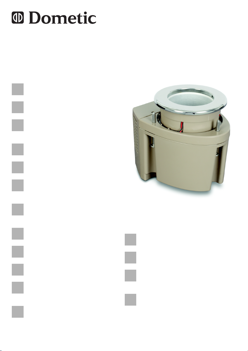
Beverage cooler
EN
DE
FRESIT
NLDASVNOFI
PT
RU
PL
CS
SK
HU
Installation and Operating Manual. . . 6
Getränkekühler
Montage- und Bedienungsanleitung 14
Refroidisseur de boisson
Instructions de montage
et de service . . . . . . . . . . . . . . . . . . 22
Enfriador de bebidas
Instrucciones de montaje y de uso . 30
Cooler bevande
Istruzioni di montaggio e d’uso . . . . 38
Drankenkoeler
Montagehandleiding en
gebruiksaanwijzing . . . . . . . . . . . . . 46
Drik køler
Monterings- og
betjeningsvejledning . . . . . . . . . . . . 54
Dryck svalare
Monterings- och bruksanvisning . . . 62
Drikke kjøligere
Monterings- og bruksanvisning . . . . 70
Juomapidike
Asennus- ja käyttöohje . . . . . . . . . . 78
Bebidas frias
Instruções de montagem e manual de
instruções . . . . . . . . . . . . . . . . . . . . 86
напитков кулер
Инструкция по монтажу и
эксплуатации . . . . . . . . . . . . . . . . . 94
Cup Cooler
Napoje Cooler
Instrukcja montażu i obsługi . . . . . 103
Nápoje Cooler
Návod k montáži a obsluze. . . . . . .111
Nápoje Cooler
Návod na montáž a uvedenie do
prevádzky . . . . . . . . . . . . . . . . . . . .119
Hűsítő Italok
Szerelési és használati útmutató . 127
Page 2

Page 3
Cup Cooler
1
1
2
2
25
150
150
1
137
150
150
3
Page 4
max. 32
Ø 102 mm
2.
3.
4.
5.
6.
1.
3
Cup Cooler
4
Page 5
Cup Cooler
2
1
4
159
174 137
130
120
102
32
38
5
5
Page 6

EN
Explanation of symbols Cup Cooler
Please read this instruction manual carefully before installation and
first use, and store it in a safe place. If you pass on the product to
another person, hand over this instruction manual along with it.
Contents
1 Explanation of symbols . . . . . . . . . . . . . . . . . . . . . . . . . . . . . . . . . . . 6
2 Safety instructions . . . . . . . . . . . . . . . . . . . . . . . . . . . . . . . . . . . . . . . 7
3 Intended use . . . . . . . . . . . . . . . . . . . . . . . . . . . . . . . . . . . . . . . . . . . 8
4 Spare parts . . . . . . . . . . . . . . . . . . . . . . . . . . . . . . . . . . . . . . . . . . . . 8
5 Installation . . . . . . . . . . . . . . . . . . . . . . . . . . . . . . . . . . . . . . . . . . . . . 9
6 Operation . . . . . . . . . . . . . . . . . . . . . . . . . . . . . . . . . . . . . . . . . . . . . 11
7 Cleaning and maintenance . . . . . . . . . . . . . . . . . . . . . . . . . . . . . . . 11
8 Troubleshooting . . . . . . . . . . . . . . . . . . . . . . . . . . . . . . . . . . . . . . . . 12
9 Warranty . . . . . . . . . . . . . . . . . . . . . . . . . . . . . . . . . . . . . . . . . . . . . 12
10 Disposal . . . . . . . . . . . . . . . . . . . . . . . . . . . . . . . . . . . . . . . . . . . . . . 12
11 Technical data . . . . . . . . . . . . . . . . . . . . . . . . . . . . . . . . . . . . . . . . . 13
1 Explanation of symbols
D
!
!
A
6
DANGER!
Safety instruction: Failure to observe this instruction will cause
fatal or serious injury.
WARNING!
Safety instruction: Failure to observe this instruction can cause
fatal or serious injury.
CAUTION!
Safety instruction: Failure to observe this instruction can lead to
injury.
NOTICE!
Failure to observe this instruction can cause material damage and
impair the function of the product.
Page 7

EN
Cup Cooler Safety instructions
NOTE
I
➤ Action: This symbol indicates that action is required on your part. The
required action is described step-by-step.
✓ This symbol describes the result of an action.
Fig. 1 5, page 3: This refers to an element in an illustration. In this case,
item 5 in figure 1 on page 3.
Supplementary information for operating the product.
2 Safety instructions
The manufacturer accepts no liability for damage in the following cases:
Damage to the product resulting from mechanical influences and excess
voltage
Alterations to the product without express permission from the manu-
facturer
Use for purposes other than those described in the operating manual
2.1 General safety
DANGER!
D
On boats: If the appliance is powered by the mains, ensure that
the power supply has a residual current circuit breaker.
!
WARNING!
Do not operate the device if it is visibly damaged.
If this device's power cable is damaged, it must be replaced by
the manufacturer, customer service or a similarly qualified
person in order to prevent safety hazards.
This device may only be repaired by qualified personnel.
Improper repairs can lead to considerable hazards.
This device can be used by children aged 8 years or over, as
well as by persons with diminished physical, sensory or mental
capacities or a lack of experience and/or knowledge, providing
they are supervised or have been taught how to use the device
safely and are aware of the resulting risks.
Cleaning and user maintenance must not be carried out by
children without supervision.
Children must not play with the device.
7
Page 8
EN
Intended use Cup Cooler
Children must be supervised to ensure that they do not play with
the device.
Always keep and use the device out of the reach of children
under the age of 8 years.
NOTICE!
A
2.2 Operating the device safely
D
A
Check that the voltage specification on the type plate
corresponds to that of the energy supply.
DANGER!
Do not touch exposed cables with your bare hands.
NOTICE!
Danger of overheating!
Ensure at all times that there is sufficient ventilation so that the
heat that arises during operation does not build up. Make sure
that the device is sufficiently far away from walls and other
objects so that the air can circulate.
Ensure that the ventilation openings are not covered.
Protect the device and the cable against heat and moisture.
3 Intended use
The Dometic Cup Cooler is a thermoelectric refrigerated cup holder. It can be
mounted into surfaces of various thicknesses.
4Spare parts
Designation Item no.
Trim ring SP-373-RING-AS-A
8
Page 9

EN
Cup Cooler Installation
5 Installation
5.1 Choosing the location
Please note the following:
Choose an installation location that does not interfere with existing below-
deck objects and has enough ventilation below the surface to help dissipate the heat generated by the thermoelectric process.
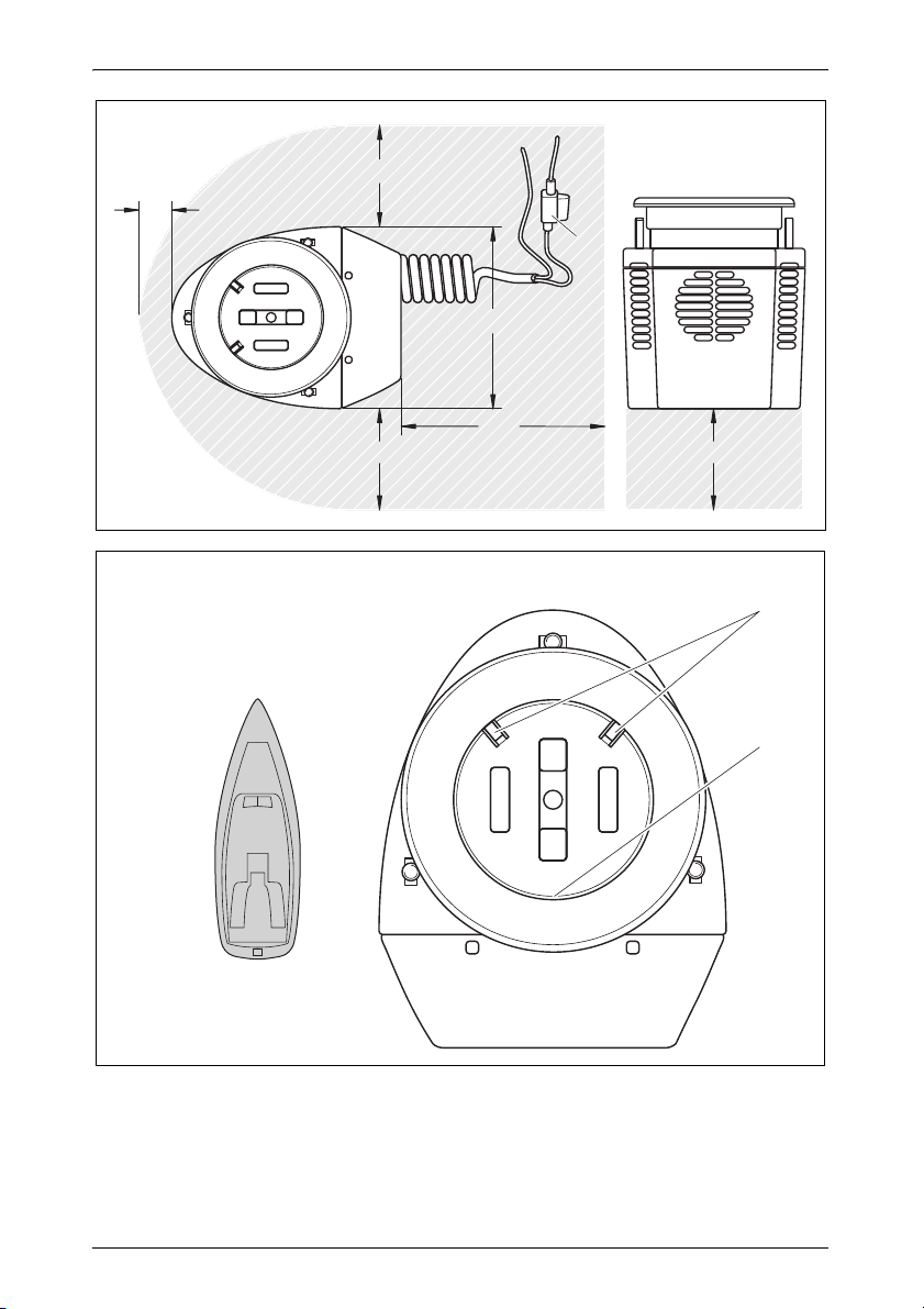
Allow 150 mm of space on all sides of the unit (fig. 1, page 3).
Make sure the chosen mounting surface is not thicker than 32 mm.
If space underneath does not have proper ventilation, an optional vent or
power vent might have to be installed to remove the built-up heat or unit
will not cool properly.
Do not locate in area where under-mounted portion of unit will receive fre-
quent seawater exposure or deck wash down.
For optimum performance, mount the cooler with the LED lights (rounded
end) toward the bow or uphill to allow gravity to pull the beverage toward
the coldest side of the cooler bore (fig. 2 2, page 3).
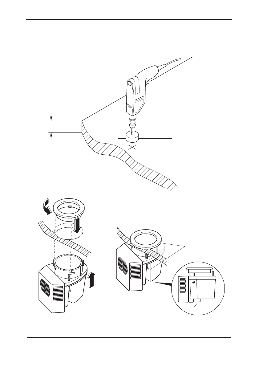
5.2 Mounting the Cup Cooler (fig. 3, page 4)
NOTICE! Risk of damage
A
Do not use power tools. Hand-tighten only. Overtightening will
cause damage to the upper trim ring locking pins.
NOTE
I
➤ Drill a 102 mm hole in the installation surface (1).
➤ Seal the raw edges of the mounting surface if applicable.
➤ Detach the stainless-steel trim ring assembly from the Cup Cooler by ro-
tating the ring clockwise then lift it off.
➤ From beneath the installation surface, slide the cup cooler upward
through the drilled hole (2).
➤ Reattach the stainless-steel trim ring assembly by aligning the ring pins to
the entry slots.
For hard surfaces such as solid fiberglass and metal, tighten the
unit down evenly by tightening each of the 3 screws 1 full revolution after surface contact. For soft surfaces such as marine plywood, tighten each of the 3 screws 2 full revolutions after surface
contact.
9
Page 10

EN
Installation Cup Cooler
➤ Lower the upper ring down on the lower body by aligning the pin into the
slot between the two LED lights (3).
➤ Turn the ring counter-clockwise until it stops (4). It only fits one way.
➤ Make sure the can pusher insert is properly aligned in bottom of Cup
Cooler with the two pushers on the same side as the two LED lights
(fig. 2 1, page 3).
➤ Tighten the three support screws until they make contact with the under-
side of the mounting surface (5).
➤ Connect a 10 mm drainage hose to the drain tube fitting on the bottom of
the unit (6).
➤ Route the output sloping downward to an appropriate drainage location
onboard.
5.3 Electrical connections (12 Volt DC only)
NOTE
I
➤ Locate (or install) an auxiliary 12 V DC power switch (not included in
scope of delivery).
Typically this will be on a fused branch circuit attached to the supply bat-
tery (not the engine battery).
➤ With the power off, attach the wires of the Cup Cooler to the wiring of that
switch. The red wire is positive and the black wire is negative.
Each unit has a 5 amp fuse built into its wiring which should be posi-
tioned in an accessible location (fig. 1 1, page 3).
➤ Power on the switch and verify the blue lights inside the Cup Cooler are lit.
Control of Cup Cooler can be managed with a single switch or
set up with zone switching.
Low-voltage cut off is at 10.5 volts DC to avoid a dead battery.
10
Page 11

EN
Cup Cooler Operation
6 Operation
NOTE
I
➤ Power on the switch that controls the Cup Cooler.
➤ Allow 2 to 3 minutes for the Cup Cooler to chill.
➤ Between sips, store your can, bottle, or any appropriately sized beverage
container in the Cup Cooler.
Make sure beverage container is in contact with optimum area
of cooler.
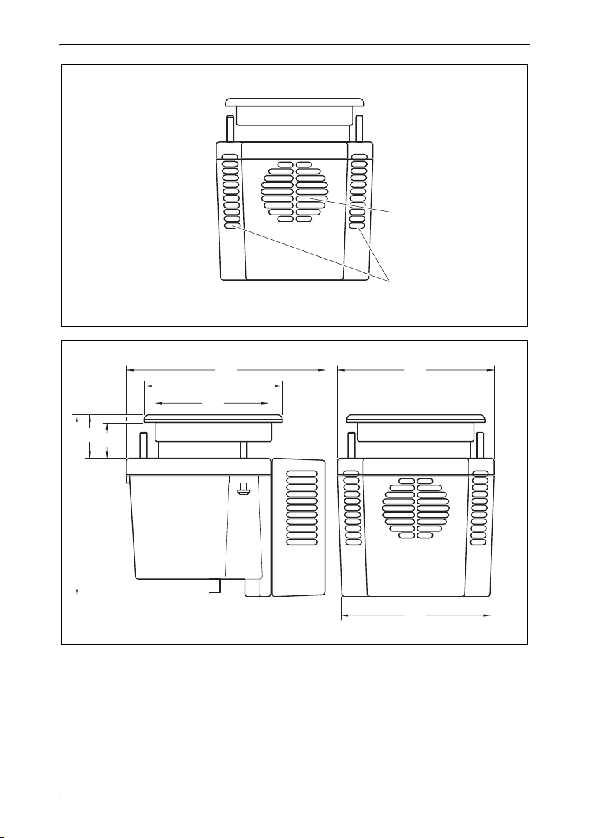
If the cooling fan is clogged with debris, wipe or brush it clean
(fig. 4 1, page 5). Do not spray with water.
Check for proper ventilation around the unit (fig. 4 2, page 5).
Poor ventilation will cause poor cooling capacity.
In cold ambient temperatures the Cup Cooler may freeze cold
beverages.
7 Cleaning and maintenance
NOTICE!
A
Do not use sharp or hard objects or cleaning agents for clean-
ing as these may damage the product.
Do not use an abrasive cleaner to clean the stainless-steel trim
ring. It will scratch the surface.
Do not use an abrasive cleaner to clean the cooler bore. It has
an anti-stick coating and it will be damaged.
➤ Occasionally clean the product with a damp cloth.
11
Page 12
EN
Troubleshooting Cup Cooler
8 Troubleshooting
Problem Possible cause Suggested remedy
LED lights are
not on when
the switch is
on.
Fuse has blown. Check for blown fuse on unit, on house
battery, or an open circuit breaker.
There is no voltage. Verify polarity of DC voltage: Positive to
positive and negative to negative.
Make sure all electrical connections are
tight.
If 12 V DC power is available and unit is
not working, unit needs to be replaced.
Unit’s high-heat cut
off is at 65 °C and if
reached, unit will shut
down. This is usually
caused by lack of air
flow or high ambient
temperature.
Ensure good ventilation.
9Warranty
The statutory warranty period applies. If the product is defective, please
contact your retailer or the manufacturer's branch in your country (see the
back of the instruction manual for the addresses).
For repair and guarantee processing, please include the following documents when you send in the device:
A copy of the receipt with purchasing date
A reason for the claim or description of the fault
10 Disposal
➤ Place the packaging material in the appropriate recycling waste bins
wherever possible.
If you wish to finally dispose of the product, ask your local recycling
centre or specialist dealer for details about how to do this in
M
12
accordance with the applicable disposal regulations.
Page 13
EN
Cup Cooler Technical data
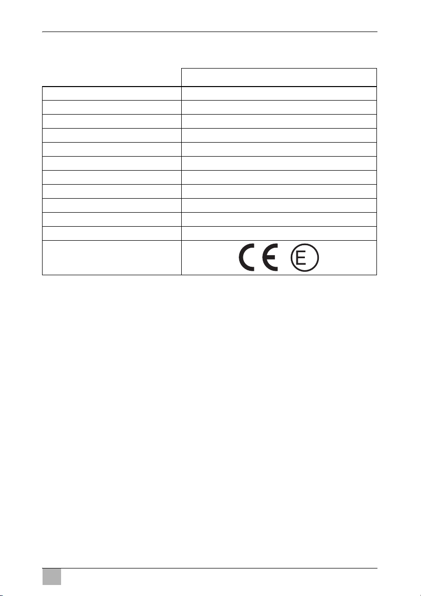
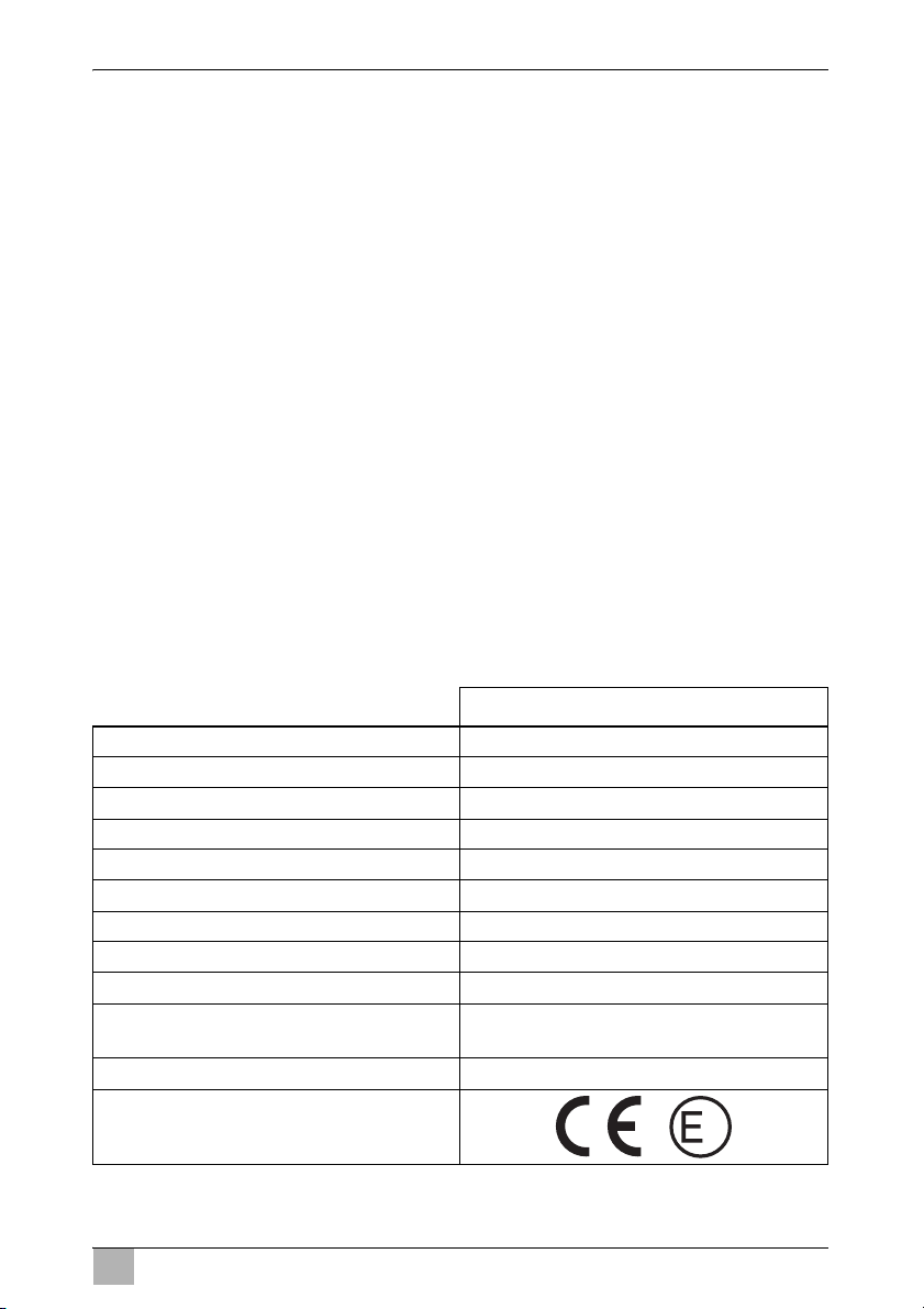
11 Technical data
Cup Cooler
Item no.: 9105330063
Rated input voltage: 12 Vg
Rated current: 3.1 A
Power consumption: 35 W (12 Vg)
Ambient temperature: +16 °C – +32 °C
Climate class: N
Interior diameter: 75 mm
Cutout diameter: 102 mm
Power cord length: ca. 40 cm
Dimensions H x W x D: 159 x 137 x 174 mm (see also fig. 5, page 5)
Weight: 960 g
Inspection/certification:
4
13
Page 14

DE
Erklärung der Symbole Cup Cooler
Bitte lesen Sie diese Anleitung vor Einbau und Inbetriebnahme sorgfältig durch und bewahren Sie sie auf. Geben Sie sie im Falle einer
Weitergabe des Produktes an den Nutzer weiter.
Inhaltsverzeichnis
1 Erklärung der Symbole . . . . . . . . . . . . . . . . . . . . . . . . . . . . . . . . . . 14
2 Sicherheitshinweise . . . . . . . . . . . . . . . . . . . . . . . . . . . . . . . . . . . . . 15
3 Bestimmungsgemäßer Gebrauch . . . . . . . . . . . . . . . . . . . . . . . . . . 16
4 Ersatzteile . . . . . . . . . . . . . . . . . . . . . . . . . . . . . . . . . . . . . . . . . . . . 16
5 Installation . . . . . . . . . . . . . . . . . . . . . . . . . . . . . . . . . . . . . . . . . . . . 17
6 Betrieb . . . . . . . . . . . . . . . . . . . . . . . . . . . . . . . . . . . . . . . . . . . . . . . 19
7 Reinigung und Pflege. . . . . . . . . . . . . . . . . . . . . . . . . . . . . . . . . . . . 19
8 Störungsbeseitigung . . . . . . . . . . . . . . . . . . . . . . . . . . . . . . . . . . . . 20
9 Gewährleistung . . . . . . . . . . . . . . . . . . . . . . . . . . . . . . . . . . . . . . . . 20
10 Entsorgung. . . . . . . . . . . . . . . . . . . . . . . . . . . . . . . . . . . . . . . . . . . . 21
11 Technische Daten . . . . . . . . . . . . . . . . . . . . . . . . . . . . . . . . . . . . . . 21
1 Erklärung der Symbole
D
!
!
A
14
GEFAHR!
Sicherheitshinweis: Nichtbeachtung führt zu Tod oder schwerer
Verletzung.
WARNUNG!
Sicherheitshinweis: Nichtbeachtung kann zu Tod oder schwerer
Verletzung führen.
VORSICHT!
Sicherheitshinweis: Nichtbeachtung kann zu Verletzungen
führen.
ACHTUNG!
Nichtbeachtung kann zu Materialschäden führen und die
Funktion des Produktes beeinträchtigen.
Page 15

DE
Cup Cooler Sicherheitshinweise
HINWEIS
I
➤ Handlung: Dieses Symbol zeigt Ihnen, dass Sie etwas tun müssen. Die
erforderlichen Handlungen werden Schritt für Schritt beschrieben.
✓ Dieses Symbol beschreibt das Ergebnis einer Handlung.
Abb. 1 5, Seite 3: Diese Angabe weist Sie auf ein Element in einer Abbil-
dung hin, in diesem Beispiel auf „Position 5 in Abbildung 1 auf Seite 3“.
Ergänzende Informationen zur Bedienung des Produktes.
2 Sicherheitshinweise
Der Hersteller übernimmt in folgenden Fällen keine Haftung für Schäden:
Beschädigungen am Produkt durch mechanische Einflüsse und Über-
spannungen
Veränderungen am Produkt ohne ausdrückliche Genehmigung vom
Hersteller
Verwendung für andere als die in der Anleitung beschriebenen Zwecke
2.1 Grundlegende Sicherheit
GEFAHR!
D
Bei Booten: Sorgen Sie bei Netzbetrieb unbedingt dafür, dass
Ihre Stromversorgung über einen FI-Schalter abgesichert ist.
!
WARNUNG!
Wenn das Gerät sichtbare Beschädigungen aufweist, dürfen
Sie es nicht in Betrieb nehmen.
Wenn das Anschlusskabel dieses Gerätes beschädigt wird,
muss es durch den Hersteller, seinen Kundendienst oder eine
ähnlich qualifizierte Person ersetzt werden, um Gefährdungen
zu vermeiden.
Reparaturen an diesem Gerät dürfen nur von Fachkräften
durchgeführt werden. Durch unsachgemäße Reparaturen können erhebliche Gefahren entstehen.
Dieses Gerät kann von Kindern ab 8 Jahren und darüber sowie
von Personen mit verringerten physischen, sensorischen oder
mentalen Fähigkeiten oder Mangel an Erfahrung und Wissen
benutzt werden, wenn sie beaufsichtigt oder bezüglich des
sicheren Gebrauchs des Gerätes unterwiesen wurden und die
daraus resultierenden Gefahren verstehen.
15
Page 16
DE
Bestimmungsgemäßer Gebrauch Cup Cooler
Reinigung und Benutzer-Wartung dürfen nicht von Kindern
ohne Beaufsichtigung durchgeführt werden.
Kinder dürfen mit dem Gerät nicht spielen.
Kinder sollten beaufsichtigt werden, um sicherzustellen, dass
sie nicht mit dem Gerät spielen.
Verwahren und benutzen Sie das Gerät außerhalb der Reich-
weite von Kindern unter 8 Jahren.
ACHTUNG!
A
2.2 Sicherheit beim Betrieb des Geräts
D
A
Vergleichen Sie die Spannungsangabe auf dem Typenschild
mit der vorhandenen Energieversorgung.
GEFAHR!
Fassen Sie nie mit bloßen Händen an blanke Leitungen.
ACHTUNG!
Überhitzungsgefahr!
Achten Sie stets darauf, dass beim Betrieb entstehende Wärme
ausreichend abgeführt werden kann. Sorgen Sie dafür, dass
das Gerät in ausreichendem Abstand zu Wänden oder Gegenständen steht, sodass die Luft zirkulieren kann.
Achten Sie darauf, dass die Lüftungsöffnungen nicht abgedeckt
werden.
Schützen Sie das Gerät und die Kabel vor Hitze und Nässe.
3 Bestimmungsgemäßer Gebrauch
Der Dometic Cup Cooler ist ein Getränkehalter mit thermoelektrischer Kühlung. Er ist zum Einbau in Oberflächen mit verschiedenen Wandstärken geeignet.
4 Ersatzteile
Bezeichnung Artikel-Nr.
Abschlussring SP-373-RING-AS-A
16
Page 17

DE
Cup Cooler Installation
5 Installation
5.1 Auswahl des Montageortes
Beachten Sie folgende Hinweise:
Wählen Sie einen Montageort, an dem vorhandene Geräte im Unterdeck
nicht beeinträchtigt werden und an dem unterhalb der Oberfläche ausreichende Belüftung gewährleistet ist, um das Abführen der Hitze zu gewährleisten, die durch thermoelektrische Prozesse entsteht.
Berücksichtigen Sie an allen Seiten des Geräts einen Freiraum von
150 mm (Abb. 1, Seite 3).
Sorgen Sie dafür, dass die für die Montage ausgewählte Oberfläche eine
Dicke von 32 mm nicht überschreitet.
Ist die Belüftung des darunter liegenden Raums nicht ausreichend, muss
möglicherweise zur Beseitigung des Hitzestaus eine Lüftungsöffnung
oder elektrische Belüftung eingebaut werden, da sonst das Gerät nicht
ausreichend gekühlt wird.
Wählen Sie keinen Ort aus, an dem der eingebaute Teil des Geräts regel-
mäßig mit Salzwasser oder Putzwasser von der Deckreinigung in Berührung kommt.
Montieren Sie den Cup Cooler so, dass die LED-Lampen (runde Seite) in
Richtung Bug oder nach oben zeigen. Dadurch zieht die Schwerkraft das
Getränk zur kältesten Seite des Cup Coolers und erzielt so eine optimale
Wirkung (Abb. 2 2, Seite 3).
5.2 Cup Cooler montieren (Abb. 3, Seite 4)
ACHTUNG! Beschädigungsgefahr
A
I
Verwenden Sie keine Elektrowerkzeuge. Befestigen Sie den Cup
Cooler nur mit der Hand. Zu starkes Anziehen verursacht Schäden an den oberen Sperrstiften des Abschlussrings.
HINWEIS
Befestigen Sie das Gerät bei harten Oberflächen, z. B. festes
Fiberglas und Metall gleichmäßig, indem Sie die 3 Schrauben
nach Kontakt mit der Oberfläche mit einer Umdrehung festziehen.
Befestigen Sie das Gerät bei weichen Oberflächen, z B.
Bootsbausperrholz, indem Sie jede der 3 Schrauben nach
Kontakt mit der Oberfläche mit zwei Umdrehungen festziehen.
17
Page 18

DE
Installation Cup Cooler
➤ Bohren Sie ein 102 mm großes Loch in den Montagegrund (1).
➤ Versiegeln Sie die Gratseiten des Montagegrunds, falls notwendig.
➤ Entfernen Sie den Abschlussring aus Edelstahl vom Cup Cooler, indem
Sie den Abschlussring im Uhrzeigersinn drehen und abheben.
➤ Schieben Sie den Cup Cooler unterhalb des Montagegrunds durch das
gebohrte Loch nach oben (2).
➤ Platzieren Sie den Abschlussring so, dass die Stifte des Abschlussrings
auf die Einsatz-Öffnungen passen.
➤ Setzen Sie den Abschlussring ein, sodass ein Stift in der Öffnung zwi-
schen den beiden LED-Lampen sitzt (3).
➤ Drehen Sie den Ring gegen den Uhrzeigersinn, bis er sich nicht mehr be-
wegen lässt (4). Er passt nur in eine Richtung.
➤ Stellen Sie sicher, dass sich der Dosen-Auswerfer am Boden des Cup
Coolers auf der selben Seite wie die beiden LEDs befindet (Abb. 2 1.
Seite 3).
➤ Ziehen Sie die drei Halteschrauben an, bis sie Kontakt mit der Unterseite
der Montagoberfläche haben (5).
➤ Schließen Sie einen 10 mm Ablaufschlauch an die Ablaufrohrverschrau-
bung an der Unterseite des Geräts an (6).
➤ Führen Sie den Ausgang schräg nach unten zu einer geeigneten Bord-
Drainage.
5.3 Elektrische Anschlüsse (nur 12 Volt Gleichspannung)
HINWEIS
I
➤ Installieren) Sie einen separaten 12 Vg-Netzschalter (nicht im Lieferum-
fang enthalten).
Er befindet sich typischerweise an einem Schaltkreis mit eigener Siche-
rung, der an die Versorgungsbatterie (nicht an die Motorbatterie) angeschlossen ist.
Der Cup Cooler kann mit einem einzelnen Schalter oder mit ei-
nem Zonenschalter bedient werden.
Die Unterspannung-Schutzabschaltung löst bei 10,5 Volt
Gleichspannung aus, um eine Entladung der Batterie zu vermeiden.
18
Page 19

DE
Cup Cooler Betrieb
➤ Schließen Sie bei abgeschalteter Spannung die Drähte des Cup Coolers
an den 12 Vg-Netzschalter an. Der rote Draht bedeutet Plus- und der
schwarze Draht Minus-Leitung.
Jedes Gerät ist mit einer 5 A-Sicherung abgesichert, die in die Verdrahtung eingebaut ist und die an einem zugänglichen Ort positioniert werden sollte (Abb. 1 1, Seite 3).
➤ Schalten Sie den Netzschalter ein und überprüfen Sie, ob die blauen
LED-Lampen im Cup Cooler leuchten.
6 Betrieb
HINWEIS
I
Sorgen Sie dafür, dass der Getränkebehälter sich im optima-
len Kühlbereich des Cup Coolers befindet.
Falls die Lüftung mit Ablagerungen verstopft ist, wischen oder
bürsten Sie sie sauber (Abb. 4 1, Seite 5). Besprühen Sie sie
niemals mit Wasser.
Prüfen Sie die ordnungsgemäße Belüftung des Geräts
(Abb. 4 2, Seite 5). Eine schlechte Belüftung verursacht eine
schlechte Kühlleistung.
Bei niedriger Umgebungstemperatur können kalte Getränke
im Cup Cooler gefrieren.
➤ Schalten Sie den Cup Cooler mit dem Netzschalter ein.
➤ Warten Sie 2 bis 3 Minuten, bis der Cup Cooler gekühlt ist.
➤ Lagern Sie in den Trinkpausen Ihre Dose, Flasche oder andere Geträn-
kebehälter in passender Größe im Cup Cooler.
7 Reinigung und Pflege
ACHTUNG!
A
➤ Reinigen Sie das Produkt gelegentlich mit einem feuchten Tuch.
Verwenden Sie zur Reinigung keine scharfen oder harten Ge-
genstände oder Reinigungsmittel, da dies zu einer Beschädigung des Geräts führen kann.
Verwenden Sie keine Scheuermittel zum Reinigen des Ab-
schlussrings. Dadurch wird die Oberfläche zerkratzt.
Verwenden Sie keine Scheuermittel zum Reinigen der Boh-
rung für den Cup Cooler. Der Cup Cooler ist mit einer Antihaftbeschichtung ausgestattet, die dadurch beschädigt wird.
19
Page 20
DE
Störungsbeseitigung Cup Cooler
8 Störungsbeseitigung
Problem Mögliche Ursache Lösungsvorschlag
Die LED-Lampen leuchten
nicht, wenn der
Netzschalter
eingeschaltet
ist.
Die Sicherung ist
durchgebrannt.
Es liegt keine Spannung an.
Falls die Übertemperatur-Schutzabschaltung 65 °C erreicht,
schaltet das Gerät
ab. Die Ursache liegt
meist an zu geringem
Luftstrom oder zu
hoher Umgebungstemperatur.
Prüfen Sie, ob die Sicherung für das Gerät
oder die Hausbatterie durchgebrannt ist
oder ob ein Leistungsschalter ausgelöst
hat.
Prüfen Sie die Polarität der Gleichspannung: Positiv mit positiv und negativ mit
negativ.
Stellen Sie sicher, dass alle elektrischen
Anschlüsse fest angeschlossen sind.
Falls die 12 V-Gleichspannung vorhanden
ist und das Gerät nicht funktioniert, muss
das Gerät ausgetauscht werden.
Achten Sie auf eine ausreichende Belüftung.
9 Gewährleistung
Es gilt die gesetzliche Gewährleistungsfrist. Sollte das Produkt defekt sein,
wenden Sie sich bitte an Ihren Fachhändler oder an die Niederlassung des
Herstellers in Ihrem Land (Adressen siehe Rückseite der Anleitung).
Zur Reparatur- bzw. Gewährleistungsbearbeitung müssen Sie folgende
Unterlagen mitschicken:
eine Kopie der Rechnung mit Kaufdatum,
einen Reklamationsgrund oder eine Fehlerbeschreibung.
20
Page 21
DE
Cup Cooler Entsorgung
10 Entsorgung
➤ Geben Sie das Verpackungsmaterial möglichst in den entsprechenden
Recycling-Müll.
Wenn Sie das Produkt endgültig außer Betrieb nehmen, informieren Sie sich bitte beim nächsten Recyclingcenter oder bei
M
Ihrem Fachhändler über die zutreffenden Entsorgungsvorschriften.
11 Technische Daten
Cup Cooler
Artikel-Nr.: 9105330063
Eingangsnennspannung: 12 Vg
Nennstrom: 3,1 A
Leistungaufnahme: 35 W (12 Vg)
Umgebungstemperatur: +16 °C – +32 °C
Klimaklasse: N
Innendurchmesser: 75 mm
Durchmesser des Ausschnitts: 102 mm
Länge Netzkabel: ca. 40 cm
Abmessungen H x B x T: 159 x 137 x 174 mm (siehe auch
Abb. 5, Seite 5)
Gewicht: 960 g
Prüfung/Zertifikat:
4
21
Page 22

FR
Symboles Cup Cooler
Veuillez lire attentivement cette notice avant le montage et la mise en
service. Veuillez ensuite la conserver. En cas de passer le produit,
veuillez le transmettre au nouvel acquéreur.
Table des matières
1 Symboles . . . . . . . . . . . . . . . . . . . . . . . . . . . . . . . . . . . . . . . . . . . . . 22
2 Consignes de sécurité . . . . . . . . . . . . . . . . . . . . . . . . . . . . . . . . . . . 23
3 Usage conforme. . . . . . . . . . . . . . . . . . . . . . . . . . . . . . . . . . . . . . . . 24
4 Pièces de rechange . . . . . . . . . . . . . . . . . . . . . . . . . . . . . . . . . . . . . 25
5 Installation . . . . . . . . . . . . . . . . . . . . . . . . . . . . . . . . . . . . . . . . . . . . 25
6 Fonctionnement . . . . . . . . . . . . . . . . . . . . . . . . . . . . . . . . . . . . . . . . 27
7 Entretien et nettoyage . . . . . . . . . . . . . . . . . . . . . . . . . . . . . . . . . . . 28
8 Guide de dépannage . . . . . . . . . . . . . . . . . . . . . . . . . . . . . . . . . . . . 28
9 Garantie . . . . . . . . . . . . . . . . . . . . . . . . . . . . . . . . . . . . . . . . . . . . . . 29
10 Retraitement . . . . . . . . . . . . . . . . . . . . . . . . . . . . . . . . . . . . . . . . . . 29
11 Caractéristiques techniques. . . . . . . . . . . . . . . . . . . . . . . . . . . . . . . 29
1 Symboles
D
!
!
A
22
DANGER !
Consigne de sécurité : le non-respect de ces consignes
entraîne la mort ou de graves blessures.
AVERTISSEMENT !
Consigne de sécurité : le non-respect de ces consignes peut
entraîner la mort ou de graves blessures.
ATTENTION !
Consigne de sécurité : le non-respect de ces consignes peut
entraîner des blessures.
AVIS !
Le non-respect de ces consignes peut entraîner des dommages
matériels et des dysfonctionnements du produit.
Page 23

FR
Cup Cooler Consignes de sécurité
REMARQUE
I
➤ Manipulation : ce symbole vous indique une action à effectuer. Les
manipulations à effectuer sont décrites étape par étape.
✓ Ce symbole décrit le résultat d’une manipulation.
Fig. 1 5, page 3 : cette information renvoie à un élément figurant sur une
illustration, dans cet exemple à la « position 5 de l'illustration 1 à la page 3 ».
Informations complémentaires sur l'utilisation du produit.
2 Consignes de sécurité
Le fabricant décline toute responsabilité pour des dommages dans les cas
suivants :
des influences mécaniques et des surtensions ayant endommagé le
matériel
des modifications apportées au produit sans autorisation explicite de la
part du fabricant
une utilisation différente de celle décrite dans la notice
2.1 Consignes générales de sécurité
DANGER !
D
Sur les bateaux : veillez à ce que votre alimentation électrique
soit sécurisée par un disjoncteur différentiel si l'appareil est
branché sur le secteur.
!
AVERTISSEMENT !
Si l'appareil présente des dégâts visibles, vous ne devez pas le
mettre en service.
Si le câble de raccordement de l'appareil est endommagé, il doit
être remplacé par le fabricant, son service après-vente ou une
personne de qualification similaire, afin d'éviter tout danger.
Seul un personnel qualifié est habilité à effectuer des répara-
tions sur l'appareil. Toute réparation mal effectuée risquerait
d'entraîner de graves dangers.
23
Page 24
FR
Usage conforme Cup Cooler
Les enfants âgés de 8 ans et plus ainsi que les personnes ayant
des déficiences physiques, sensorielles ou mentales ou un
manque d'expérience ou de connaissances peuvent utiliser ce
produit à condition d'être sous surveillance ou d'avoir reçu des
instructions concernant l'utilisation de l'appareil en toute
sécurité et de comprendre les dangers qui en résultent.
Le nettoyage et la maintenance ne doivent pas être effectués
par des enfants sans surveillance.
Les enfants ne doivent pas jouer avec l'appareil.
Les enfants doivent être surveillés pour s'assurer qu'ils ne
jouent pas avec l'appareil.
Placez et utilisez l'appareil hors de portée des enfants de moins
de 8 ans.
AVIS !
A
2.2 Sécurité lors de l'utilisation de l'appareil
D
Vérifiez que la tension indiquée sur la plaque signalétique cor-
respond à l'alimentation électrique dont vous disposez.
DANGER !
Ne touchez jamais les lignes électriques dénudées avec les
mains nues.
AVIS !
A
Risque de surchauffe
Veillez toujours à ce que la chaleur produite lors du fonctionnement puisse se dissiper suffisamment. Veillez à ce que l'appareil se trouve à distance suffisante des murs ou des objets, de
sorte que l'air puisse circuler.
Assurez-vous que les ouvertures d'aération ne sont pas recou-
vertes.
Tenez l'appareil et les câbles à l'abri de la chaleur et de l'humi-
dité.
3 Usage conforme
Le Cup Cooler de Dometic est un support pour boissons à refroidissement
thermoélectrique. Il est conçu pour être encastré dans des surfaces présentant des épaisseurs de paroi différentes.
24
Page 25
FR
Cup Cooler Pièces de rechange
4 Pièces de rechange
Désignation N° d'article
Anneau de fermeture SP-373-RING-AS-A
5 Installation
5.1 Choix de l'emplacement de montage
Tenez compte des remarques suivantes :
choisissez un emplacement de montage ne compromettant pas le fonc-
tionnement des appareils se trouvant sur le pont inférieur et disposant
d'une ventilation suffisante sous la surface, afin de garantir l'évacuation
de la chaleur se formant du fait des processus thermoélectriques.
De tous les côtés de l'appareil, prévoyez une marge de 150 mm (fig. 1,
page 3).
Veillez à ce que la surface choisie pour le montage ne dépasse pas une
épaisseur de 32 mm.
Si la ventilation de l'espace se trouvant en dessous n'est pas suffisante,
il faut éventuellement prévoir une ouverture d'aération pour éliminer l'accumulation de chaleur ou monter une ventilation électrique. Dans le cas
contraire, l'appareil n'est pas assez refroidi.
Ne choisissez pas un emplacement où la partie encastrée de l'appareil
entre régulièrement en contact avec de l'eau salée ou de l'eau provenant
du nettoyage du pont.
Montez le Cup Cooler de telle sorte que les lampes à LED (côté rond)
soient orientées vers la proue ou vers le haut. De ce fait, la gravité attire
la boisson du côté le plus froid du Cup Cooler et permet d'obtenir ainsi un
effet optimal (fig. 2 2, page 3).
25
Page 26

FR
Installation Cup Cooler
5.2 Montage du Cup Cooler (fig. 3, page 4)
AVIS ! Risque d'endommagement
A
I
➤ Percez un trou d'une taille de 102 mm dans la surface de montage (1).
➤ Si nécessaire, colmatez les bavures de la surface de montage.
➤ Retirez l'anneau de fermeture en inox du Cup Cooler, en tournant l'an-
neau dans le sens horaire et en le soulevant.
➤ Glissez le Cup Cooler sous la surface de montage, par le trou percé, vers
le haut (2).
➤ Placez l'anneau de fermeture de telle sorte que les broches de l'anneau
correspondent aux ouvertures de l'insert.
➤ Insérez l'anneau de fermeture de telle sorte qu'une broche se trouve dans
l'ouverture entre les deux lampes à LED (3).
➤ Tournez l'anneau dans le sens anti-horaire jusqu'à ce qu'il ne puisse plus
être déplacé (4). Il ne rentre que dans un sens.
➤ Assurez-vous que l'éjecteur de cannette au fond du Cup Cooler se trouve
du même côté que les deux LED (fig. 2 1, page 3).
➤ Serrez les trois vis de maintien jusqu'à ce qu'elles soient en contact avec
la partie inférieure de la surface de montage (5).
➤ Raccordez un flexible d'évacuation de 10 mm au raccord vissé du flexible
d'évacuation, sous le dessous de l'appareil (6).
➤ Posez l'évacuation vers le bas, jusqu'à un drainage de bord adapté.
N'employez pas d'outils électriques. Fixez le Cup Cooler à la main
uniquement. Un serrage trop fort provoque des dommages sur les
broches supérieures de l'anneau de fermeture.
REMARQUE
Sur les surfaces dures, p. ex. fibre de verre solide et métal,
fixez l'appareil de manière homogène, en serrant d'un tour les
3 vis après le contact avec la surface.
Sur les surfaces souples, p. ex. contreplaqué pour la construc-
tion de bateaux, fixez l'appareil en serrant de deux tours les 3
vis après le contact avec la surface.
26
Page 27

FR
Cup Cooler Fonctionnement
5.3 Raccordements électriques (uniquement 12 Volts
tension continue)
REMARQUE
I
➤ Trouvez (ou installez) un commutateur 12 Vg séparé (non fourni à la li-
vraison).
Il se trouve, en règle générale, sur un circuit de commutation disposant
de son propre fusible et raccordé à la batterie domestique (pas à la batterie du moteur).
➤ Lorsque la tension est éteinte, raccordez les fils du Cup Cooler au com-
mutateur 12 Vg. Le fil rouge est la ligne plus et le fil noir la ligne moins.
Chaque appareil est protégé par un fusible de 5 A intégré dans le
câblage et qui doit être placé dans un endroit accessible (fig. 1 1,
page 3).
➤ Allumez le commutateur et vérifiez si les lampes à LED bleues du Cup
Cooler s'allument.
Il est possible de commander le Cup Cooler avec un seul in-
terrupteur ou un commutateur de zone.
Le dispositif d'arrêt de sous-tension se déclenche à 10,5 V de
courant continu, afin d'éviter une décharge de la batterie.
6 Fonctionnement
REMARQUE
I
➤ Mettez le Cup Cooler en marche à l'aide du commutateur.
➤ Attendez 2 à 3 minutes que le Cup Cooler soit froid.
Veillez à ce que le conteneur de boisson se trouve dans la
zone de refroidissement optimale du Cup Cooler.
Si l'aération est bouchée par des dépôts, nettoyez-la en l'es-
suyant ou en la brossant (fig. 4 1, page 5). Ne pulvérisez jamais d'eau sur l'aération.
Vérifiez que la ventilation de l'appareil fonctionne correcte-
ment (fig. 4 2, page 5). Une mauvaise ventilation entraîne
une mauvaise puissance frigorifique.
En cas de faible température ambiante, les boissons froides
peuvent geler dans le Cup Cooler.
27
Page 28
FR
Entretien et nettoyage Cup Cooler
➤ Lorsque vous ne buvez plus, posez votre cannette, votre bouteille ou
d'autres conteneurs de boisson de taille correspondante dans le Cup
Cooler.
7 Entretien et nettoyage
AVIS !
A
➤ Nettoyez de temps en temps le produit avec un chiffon humide.
N’utilisez aucun objet coupant ou dur, ni de détergents pour le
nettoyage. Cela pourrait endommager l'appareil.
N'utilisez pas de détergents pour nettoyer l'anneau de ferme-
ture. Cela rayerait la surface.
N'utilisez pas de détergents pour nettoyer le perçage pour le
Cup Cooler. Le Cup Cooler est doté d'un revêtement anti-adhésif qui serait alors endommagé.
8 Guide de dépannage
Problème Cause possible Solution proposée
Les lampes à
LED ne s'allument pas
lorsque le commutateur est
allumé.
Le fusible est grillé. Vérifiez si le fusible de l'appareil ou de la
batterie a grillé ou si un disjoncteur s'est
déclenché.
Il n'y a pas de tension
d'alimentation.
Si le dispositif de protection contre la surchauffe atteint 65 °C,
l'appareil s'éteint. La
cause est souvent un
flux d'air trop faible
ou une température
ambiante trop élevée.
Vérifiez la polarité de la tension continue :
positive avec positive et négative avec
négative.
Assurez-vous que tous les raccordements
électriques sont bien fixés.
S'il y a une tension continue de 12 V et
que l'appareil ne fonctionne pas, l'appareil
doit être remplacé.
Assurez-vous que l'aération est suffisante.
28
Page 29
FR
Cup Cooler Garantie
9 Garantie
Le délai légal de garantie s'applique. Si le produit s'avérait défectueux,
veuillez vous adresser à la filiale du fabricant située dans votre pays (voir
adresses au verso du présent manuel) ou à votre revendeur spécialisé.
Veuillez y joindre les documents suivants pour la gestion des réparations et
de la garantie :
une copie de la facture avec la date d'achat,
le motif de la réclamation ou une description du dysfonctionnement.
10 Retraitement
➤ Jetez les emballages dans les conteneurs de déchets recyclables prévus
à cet effet.
Lorsque vous mettrez votre produit définitivement hors service,
informez-vous auprès du centre de recyclage le plus proche ou
M
auprès de votre revendeur spécialisé sur les prescriptions relatives
au retraitement des déchets.
11 Caractéristiques techniques
Cup Cooler
N° d'article : 9105330063
Tension nominale d'entrée : 12 Vg
Courant nominal : 3,1 A
Puissance absorbée : 35 W (12 Vg)
Température ambiante : +16 °C – +32 °C
Classe climatique : N
Diamètre interne : 75 mm
Diamètre de la découpe : 102 mm
Longueur câble secteur : env. 40 cm
Dimensions h x L x l : 159 x 137 x 174 mm (voir aussi fig. 5,
page 5)
Poids : 960 g
Contrôle/Certificat :
4
29
Page 30

ES
Explicación de los símbolos Cup Cooler
Lea detenidamente estas instrucciones antes de llevar a cabo la instalación y puesta en funcionamiento, y consérvelas en un lugar seguro.
En caso de vender o entregar el producto a otra persona, entregue
también estas instrucciones.
Índice
1 Explicación de los símbolos. . . . . . . . . . . . . . . . . . . . . . . . . . . . . . . 30
2 Indicaciones de seguridad . . . . . . . . . . . . . . . . . . . . . . . . . . . . . . . . 31
3 Uso adecuado . . . . . . . . . . . . . . . . . . . . . . . . . . . . . . . . . . . . . . . . . 32
4 Piezas de repuesto . . . . . . . . . . . . . . . . . . . . . . . . . . . . . . . . . . . . . 33
5 Instalación . . . . . . . . . . . . . . . . . . . . . . . . . . . . . . . . . . . . . . . . . . . . 33
6 Funcionamiento . . . . . . . . . . . . . . . . . . . . . . . . . . . . . . . . . . . . . . . . 35
7 Limpieza y mantenimiento . . . . . . . . . . . . . . . . . . . . . . . . . . . . . . . . 36
8 Solución de averías . . . . . . . . . . . . . . . . . . . . . . . . . . . . . . . . . . . . . 36
9 Garantía legal . . . . . . . . . . . . . . . . . . . . . . . . . . . . . . . . . . . . . . . . . 37
10 Gestión de residuos . . . . . . . . . . . . . . . . . . . . . . . . . . . . . . . . . . . . . 37
11 Datos técnicos . . . . . . . . . . . . . . . . . . . . . . . . . . . . . . . . . . . . . . . . . 37
1 Explicación de los símbolos
D
!
!
A
30
¡PELIGRO!
Indicación de seguridad: su incumplimiento acarrea la muerte o
graves lesiones.
¡ADVERTENCIA!
Indicación de seguridad: su incumplimiento puede acarrear la
muerte o graves lesiones.
¡ATENCIÓN!
Indicación de seguridad: su incumplimiento puede acarrear
lesiones.
¡AVISO!
Su incumplimiento puede acarrear daños materiales y perjudicar
el correcto funcionamiento del producto.
Page 31

ES
Cup Cooler Indicaciones de seguridad
NOTA
I
➤ Paso a seguir: este símbolo le indica que debe realizar un paso. Todos
los procedimientos necesarios se describen paso a paso.
✓ Este símbolo describe el resultado de un paso realizado.
Fig. 1 5, página 3: esta indicación hace referencia a un elemento de una
figura, en este ejemplo a la “Posición 5 en la figura 1 de la página 3”.
Información adicional para el manejo del producto.
2 Indicaciones de seguridad
El fabricante declina toda responsabilidad ante daños ocurridos en los
siguientes casos:
daños en el producto debido a influencias mecánicas y sobretensiones
modificaciones realizadas en el producto sin el expreso consentimiento
del fabricante
utilización del aparato para fines distintos a los descritos en las instruc-
ciones.
2.1 Seguridad básica
¡PELIGRO!
D
En embarcaciones: en caso de funcionamiento conectado a la
red eléctrica, asegúrese de que el suministro de corriente esté
protegido con un interruptor diferencial.
!
¡ADVERTENCIA!
No ponga el aparato en funcionamiento si presenta desperfec-
tos visibles.
Si se daña el cable de conexión del aparato, el fabricante, su
servicio de atención al cliente o una persona cualificada debe
reemplazarlo para evitar así posibles peligros.
Solo personal especializado está autorizado a realizar repara-
ciones en el aparato. Una reparación incorrecta entraña riesgos
considerables.
31
Page 32

ES
Uso adecuado Cup Cooler
Los niños mayores de 8 años y las personas de capacidad
física, sensorial o mental disminuida, así como aquellas personas con falta de experiencia y conocimientos suficientes solo
podrán utilizar este aparato bajo vigilancia o si han sido instruidos respecto al uso seguro del aparato y a los posibles peligros
que pueden emanar de él.
Los niños solo podrán realizar las tareas de limpieza y mante-
nimiento bajo vigilancia.
Los niños no están autorizados a jugar con el aparato.
Controle a los niños para asegurarse de que no jueguen con el
aparato.
Mantenga y utilice el aparato fuera del alcance de los niños me-
nores de 8 años.
¡AVISO!
A
2.2 Seguridad durante el funcionamiento del aparato
D
Compare el valor de tensión indicado en la placa de caracterís-
ticas con el suministro de energía existente.
¡PELIGRO!
No toque directamente con las manos cables sin aislamiento.
¡AVISO!
A
¡Peligro de sobrecalentamiento!
Asegúrese de que quede constantemente garantizada una salida adecuada del calor que se desprende durante el funcionamiento. Asegúrese también de que el aparato guarde la
suficiente distancia respecto a paredes u objetos, de forma que
el aire pueda circular.
Evite que se obstruyan las aberturas de ventilación.
Proteja el aparato y los cables del calor y de la humedad.
3 Uso adecuado
El Dometic Cup Cooler es un soporte para bebidas con refrigeración termoeléctrica. Éste puede montarse en superficies con diversos grosores de
pared.
32
Page 33

ES
Cup Cooler Piezas de repuesto
4 Piezas de repuesto
Denominación N.° de artículo
Anillo terminal SP-373-RING-AS-A
5 Instalación
5.1 Elección del lugar de montaje
Tenga en cuenta las siguientes indicaciones:
Escoja un lugar de montaje donde no quede afectado el funcionamiento
de los aparatos existentes en la cubierta inferior y donde quede garantizada la suficiente ventilación por debajo de la superficie de colocación,
para asegurar así la salida al exterior del calor generado por los procesos
termoeléctricos.
Deje en todos los lados del aparato una distancia de separación de
150 mm (fig. 1, página 3).
Preste atención a que la superficie elegida para el montaje no tenga un
grosor superior a 32 mm.
Si no hay suficiente ventilación del espacio que queda por debajo, deberá
instalarse una abertura de ventilación o una ventilación eléctrica para evitar la acumulación de calor; de lo contrario, el aparato no se refrigera lo
suficiente.
No escoja lugares de montaje donde haya piezas del aparato que estén
continuamente en contacto con el agua salada o con el agua usada para
limpiar la cubierta.
Monte el Cup Cooler de forma que las lámparas LED (lado redondo) que-
den orientadas mirando a la proa o hacia arriba. De esta manera, la
fuerza de gravedad coloca las bebidas en el lado más frío del Cup Cooler
y se obtendrá una refrigeración óptima (fig. 2 2, página 3).
33
Page 34

ES
Instalación Cup Cooler
5.2 Montar el Cup Cooler (fig. 3, página 4)
¡AVISO! Peligro de ocasionar daños materiales
A
I
➤ Perfore un orificio amplio de 102 mm en la base de montaje (1).
➤ Selle los lados de rebaba de la base de montaje en caso necesario.
➤ Retire el anillo terminal de acero inoxidable del Cup Cooler girándolo en
el sentido de las agujas del reloj.
➤ Pase el Cup Cooler por debajo de la base de montaje a través del orificio
perforado y desplácelo hacia arriba (2).
➤ Coloque el anillo terminal de forma que sus pasadores se introduzcan en
las aberturas.
➤ Introduzca el anillo terminal de forma que un pasador quede colocado en
la abertura entre las dos lámparas LED (3).
➤ Gire el anillo en sentido contrario a las agujas del reloj hasta que no pue-
da moverse más (4). Éste sólo cabe en una dirección.
➤ Asegúrese de que el dispositivo de expulsión de latas en el fondo del Cup
Cooler queda al mismo lado que los dos LEDs (fig. 2 1, página 3).
➤ Apriete los tres tornillos del soporte hasta que hagan contacto con la par-
te inferior de la superficie de montaje (5).
➤ Conecte una manguera de salida de 10 mm a la unión roscada de tubos
de salida situada en la parte inferior del aparato (6).
➤ Conduzca hacia abajo la salida un poco inclinada hasta llegar a un dispo-
sitivo apropiado de drenaje a bordo.
No utilice herramientas eléctricas. Fije únicamente a mano el Cup
Cooler. Si lo aprieta demasiado pueden producirse daños en los
pasadores de bloqueo superiores del anillo terminal.
NOTA
En superficies duras, p. ej. fibra de vidrio rígida y metales, fije
el aparato de forma uniforme, girando una vuelta los 3 tornillos
una vez que estos entren en contacto con la superficie.
En superficies blandas, p. ej. madera contrachapada para la
construcción de embarcaciones, fije el aparato girando dos
vueltas los 3 tornillos una vez que estos entren en contacto
con la superficie.
34
Page 35

ES
Cup Cooler Funcionamiento
5.3 Conexiones eléctricas (sólo 12 voltios de tensión
continua)
NOTA
I
➤ Busque (o instale) un interruptor de red separado de 12 Vg (no incluido
en el volumen de entrega).
Éste suele encontrarse en un circuito con un fusible propio conectado a
la batería de servicio (no a la batería del motor).
➤ Con la tensión desconectada, conecte los conductores del Cup Cooler al
interruptor de red de 12 Vg. El conductor rojo corresponde al cable positivo y el conductor negro al cable negativo.
Cada aparato está protegido con un fusible de 5 A que está integrado en
el cableado y que debería colocarse en un lugar fácilmente accesible
(fig. 1 1, página 3).
➤ Conecte el interruptor de red y compruebe si se iluminan las lámparas
LED azules del Cup Cooler.
El Cup Cooler puede funcionar con un único interruptor o con
un conmutador de zona.
La desconexión de protección contra subtensión se activa con
una tensión continua de 10,5 voltios para evitar que la batería
se descargue.
6 Funcionamiento
NOTA
I
➤ Conecte el interruptor de red del Cup Cooler.
Encárguese de que el soporte para bebidas se sitúe en el área
de refrigeración óptima del Cup Cooler.
Si la ventilación está atascada con sedimentaciones, retírelas
llevando a cabo una limpieza (fig. 4 1, página 5). No la rocíe
nunca con agua.
Compruebe si existe una ventilación correcta del aparato
(fig. 4 2, página 5). La mala ventilación da como resultado
una mala potencia de refrigeración.
Con una temperatura ambiente baja, las bebidas frías pueden
llegar a congelarse en el Cup Cooler.
35
Page 36

ES
Limpieza y mantenimiento Cup Cooler
➤ Espere entre 2 y 3 minutos hasta que se haya enfriado el Cup Cooler.
➤ Guarde siempre que quiera en el Cup Cooler la lata, botella u otro reci-
piente de bebidas con el tamaño adecuado.
7 Limpieza y mantenimiento
¡AVISO!
A
➤ Limpie de vez en cuando el producto con un paño húmedo.
Para la limpieza no utilice ningún objeto afilado o duro ni de-
tergentes, ya que ello podría dañar el aparato.
No utilice productos abrasivos para limpiar el anillo terminal.
Estos pueden arañar la superficie.
No utilice productos abrasivos para limpiar el orificio del Cup
Cooler. El Cup Cooler cuenta con un recubrimiento antiadherente que puede quedar dañado.
8 Solución de averías
Problema Posible causa Propuesta de solución
Las lámparas
LED no se iluminan cuando
el interruptor
de red está
conectado.
Se ha fundido el fusible. Compruebe si el fusible del aparato o
de la batería de servicio está fundido o
si ha saltado un seccionador de potencia.
No hay tensión. Compruebe la polaridad de la tensión
continua: positivo con positivo y negativo con negativo.
Asegúrese de que todas las conexiones eléctricas estén bien enchufadas.
Si existe tensión continua de 12 V y el
aparato no funciona, éste deberá
reemplazarse.
Si se alcanza la desconexión de protección
contra sobretemperatura de 65 °C, el aparato
se desconecta. La causa
suele ser una corriente
de aire escasa o una
temperatura ambiente
elevada.
Procure que exista suficiente ventilación.
36
Page 37

ES
Cup Cooler Garantía legal
9 Garantía legal
Rige el plazo de garantía legal. Si el producto presenta algún defecto,
diríjase a su establecimiento especializado o a la sucursal del fabricante de
su país (ver direcciones en el dorso de estas instrucciones).
Para la tramitación de la reparación y de la garantía debe enviar también los
siguientes documentos:
una copia de la factura con fecha de compra,
el motivo de la reclamación o una descripción de la avería.
10 Gestión de residuos
➤ Deseche el material de embalaje en el contenedor de reciclaje correspon-
diente.
Cuando vaya a desechar definitivamente el producto, infórmese en
el centro de reciclaje más cercano o en un comercio especializado
M
sobre las normas pertinentes de eliminación de materiales.
11 Datos técnicos
Cup Cooler
N.º de artículo: 9105330063
Tensión nominal de entrada: 12 Vg
Corriente nominal: 3,1 A
Consumo de potencia: 35 W (12 Vg)
Temperatura ambiente: +16 °C a +32 °C
Clase climática: N
Diámetro interior: 75 mm
Diámetro de la abertura: 102 mm
Longitud del cable de red: aprox. 40 cm
Dimensiones H x A x P: 159 x 137 x 174 mm (véase también
fig. 5, página 5)
Peso: 960 g
Homologación/certificados:
4
37
Page 38

IT
Spiegazione dei simboli Cup Cooler
Prima di effettuare il montaggio e la messa in funzione leggere
accuratamente questo manuale di istruzioni, conservarlo e in caso di
trasmissione del prodotto, consegnarlo all'utente successivo.
Indice
1 Spiegazione dei simboli . . . . . . . . . . . . . . . . . . . . . . . . . . . . . . . . . . 38
2 Indicazioni di sicurezza . . . . . . . . . . . . . . . . . . . . . . . . . . . . . . . . . . 39
3 Uso conforme alla destinazione. . . . . . . . . . . . . . . . . . . . . . . . . . . . 40
4 Pezzi di ricambio . . . . . . . . . . . . . . . . . . . . . . . . . . . . . . . . . . . . . . . 40
5 Installazione . . . . . . . . . . . . . . . . . . . . . . . . . . . . . . . . . . . . . . . . . . . 41
6 Funzionamento . . . . . . . . . . . . . . . . . . . . . . . . . . . . . . . . . . . . . . . . 43
7 Pulizia e cura . . . . . . . . . . . . . . . . . . . . . . . . . . . . . . . . . . . . . . . . . . 43
8 Risoluzione dei guasti . . . . . . . . . . . . . . . . . . . . . . . . . . . . . . . . . . . 44
9 Garanzia . . . . . . . . . . . . . . . . . . . . . . . . . . . . . . . . . . . . . . . . . . . . . 44
10 Smaltimento . . . . . . . . . . . . . . . . . . . . . . . . . . . . . . . . . . . . . . . . . . . 45
11 Specifiche tecniche . . . . . . . . . . . . . . . . . . . . . . . . . . . . . . . . . . . . . 45
1 Spiegazione dei simboli
D
!
!
A
38
PERICOLO!
Avviso di sicurezza: la mancata osservanza di questo avviso
comporta ferite gravi anche mortali.
AVVERTENZA!
Avviso di sicurezza: la mancata osservanza di questo avviso
può causare ferite gravi anche mortali.
ATTENZIONE!
Avviso di sicurezza: la mancata osservanza di questo avviso
può essere causa di lesioni.
AVVISO!
La mancata osservanza di questa nota può causare danni materiali e compromettere il funzionamento del prodotto.
Page 39

IT
Cup Cooler Indicazioni di sicurezza
NOTA
I
➤ Modalità di intervento: questo simbolo indica all'utente che è necessario
un intervento. Le modalità di intervento necessarie saranno descritte
passo dopo passo.
✓ Questo simbolo descrive il risultato di un intervento.
Fig. 1 5, pagina 3: questi dati si riferiscono ad un elemento in una figura,
in questo caso alla “posizione 5 nella figura 1 a pagina 3”.
Informazioni integranti relative all'impiego del prodotto.
2 Indicazioni di sicurezza
Il produttore non si assume nessuna responsabilità per danni nei seguenti
casi:
danni al prodotto dovuti a influenze meccaniche o a sovratensioni
modifiche al prodotto senza esplicita autorizzazione del produttore
impiego per altri fini rispetto a quelli descritti nel manuale di istruzioni
2.1 Sicurezza di base
PERICOLO!
D
Per le imbarcazioni: con il collegamento alla rete fare in modo
che l'alimentazione elettrica sia sempre controllata da un interruttore differenziale.
!
AVVERTENZA!
Se il dispositivo presenta danni visibili, non metterlo in funzione.
Se il cavo di collegamento di questo dispositivo viene danneg-
giato, esso deve essere sostituito dal produttore, dal suo servizio assistenza clienti o da personale ugualmente qualificato, al
fine di evitare pericoli.
Questo dispositivo può essere riparato solo da personale spe-
cializzato. Possono insorgere gravi pericoli in seguito a riparazioni non eseguite in maniera corretta.
Il presente dispositivo può essere usato sia da bambini dagli 8
anni in su, sia da persone con ridotte capacità fisiche, sensoriali
o mentali o con poca esperienza o conoscenze, se non lasciati
soli o se istruiti sul suo utilizzo sicuro e in grado di capire i pericoli che possono sorgere.
39
Page 40

IT
Uso conforme alla destinazione Cup Cooler
La pulizia e la manutenzione da parte dell’utente non possono
essere compiute da bambini lasciati soli.
I bambini non devono giocare con il dispositivo.
Controllare che i bambini non giochino con il dispositivo.
Conservare e utilizzare il dispositivo lontano dalla portata dei
bambini al di sotto degli 8 anni.
AVVISO!
A
2.2 Sicurezza durante il funzionamento del dispositivo
D
A
Confrontare i dati della tensione riportati sulla targhetta con
quelli delle prese e degli attacchi disponibili.
PERICOLO!
Non toccare mai i cavi scoperti a mani nude.
AVVISO!
Pericolo di surriscaldamento!
Assicurarsi sempre che il calore generato durante il funzionamento fuoriesca sufficientemente. Fare in modo che la distanza
fra il dispositivo e le pareti o altri oggetti sia tale da permettere
all'aria di circolare liberamente.
Fare attenzione che le aperture di aerazione non vengano co-
perte.
Proteggere il dispositivo e i cavi dal caldo e dall’umidità.
3 Uso conforme alla destinazione
Dometic Cup Cooler è un porta-bibite con refrigerazione termoelettrica. Può
essere installato in superfici di vari spessori.
4 Pezzi di ricambio
Denominazione N. articolo
Anello di tenuta SP-373-RING-AS-A
40
Page 41

IT
Cup Cooler Installazione
5 Installazione
5.1 Scelta del luogo di montaggio
Osservare le seguenti avvertenze.
Scegliere un luogo di montaggio che non comprometta il funzionamento
di altri dispositivi in sottocoperta e che garantisca sufficiente aerazione
per il dispositivo, per espellere il calore che si accumula con i processi termoelettrici.
Lasciare libero uno spazio di 150 mm su ogni lato del dispositivo (fig. 1,
pagina 3).
Assicurarsi che la superficie scelta per il montaggio non abbia uno spes-
sore superiore a 32 mm.
Se l'aerazione dell'ambiente sottostante non è sufficiente, per eliminare il
calore che vi si accumula può essere necessario installare un'apertura o
un sistema di aerazione, altrimenti il dispositivo non viene
sufficientemente raffreddato.
Evitare luoghi in cui il componente incassato del dispositivo entri conti-
nuamente in contatto con acqua salata o con l'acqua di lavaggio del
ponte.
Montare il Cup Cooler in modo tale che i LED (lato arrotondato) siano
rivolti a prua o verso l'alto. In questo modo la forza di gravità preme la bevanda sul lato più freddo del Cup Cooler per fornire un risultato ottimale
(fig. 2 2, pagina 3).
5.2 Montaggio (fig. 3, pagina 4)
AVVISO! Pericolo di danni
A
I
Non usare strumenti elettrici. Fissare il Cup Cooler solo con le
mani. Un serraggio troppo stretto causa danni alle dentature di fissaggio superiori dell'anello di tenuta.
NOTA
Se si fissa il dispositivo su superfici rigide, ad es. su fibra di
vetro rigida e su metallo, serrare le 3 viti in modo uniforme,
dopo il contatto con la superficie, applicando con una
rotazione.
Se lo si fissa su superfici non dure, ad es. su compensato ma-
rino, serrare ognuna delle 3 viti, dopo il contatto con la superficie, con due rotazioni.
41
Page 42

IT
Installazione Cup Cooler
➤ Praticare un foro da 102 mm sulla base di montaggio (1).
➤ Sigillare i bordi della base di montaggio se necessario.
➤ Estrarre l'anello di tenuta in acciaio dal Cup Cooler girandolo in senso ora-
rio e sollevandolo.
➤ Inserire il Cup Cooler dalla parte inferiore della base di montaggio, spin-
gendolo verso l'alto attraverso il foro praticato (2).
➤ Posizionare l'anello di tenuta facendo sì che i dentini del medesimo coin-
cidano con le guide di fissaggio.
➤ Inserire l'anello in modo tale che un dentino si trovi nell'apertura tra i due
LED (3).
➤ Ruotare l'anello in senso antiorario fino alla battuta (4). Può essere avvi-
tato solo in una direzione.
➤ Assicurarsi che l'espulsore lattine sul fondo del Cup Cooler si trovi sullo
stesso lato dei due LED (fig. 2 1, pagina 3).
➤ Serrare le tre viti di fissaggio fino a che non toccano il lato inferiore della
superficie di montaggio (5).
➤ Collegare un tubo flessibile da 10 mm all'attacco del tubo di scarico,
posizionato sul lato inferiore del dispositivo (6).
➤ Portare lo scarico in obliquo verso il basso in un apposito drenaggio di
bordo.
5.3 Collegamenti elettrici (solo tensione continua da
12 volt)
NOTA
I
➤ Trovare (o installare) un interruttore di rete separato da 12 Vg (non for-
nito in dotazione).
Normalmente si trova in un circuito con il proprio fusibile e viene colle-
gato alla batteria di bordo (non alla batteria del motore).
➤ Collegare, con la tensione staccata, i cavi del Cup Coolers all'interruttore
di rete da 12 Vg. Il cavo rosso va al polo positivo e quello nero a quello
negativo.
Il Cup Cooler può essere attivato con un interruttore singolo o
un interruttore di zona.
Il fusibile di sotto tensione si stacca a 10,5 volt di tensione con-
tinua per evitare di scaricare la batteria.
42
Page 43

IT
Cup Cooler Funzionamento
Ogni dispositivo è protetto da un fusibile da 5 A, integrato nel cablaggio,
che deve essere posizionato in un punto accessibile (fig. 1 1,
pagina 3).
➤ Attivare l'interruttore di rete e verificare che si accendano i LED blu nel
Cup Cooler.
6 Funzionamento
NOTA
I
➤ Accendere il Cup Cooler con l'interruttore di rete.
➤ Attendere da 2 a 3 minuti che il Cup Cooler si raffreddi.
➤ Posizionare nel Cup Cooler lattine, bottiglie o altri contenitori di dimensio-
ni idonee.
Assicurarsi che la bibita si trovi in nella posizione di raffredda-
mento ottimale del Cup Cooler.
Se l'aerazione è bloccata da depositi, pulirla con un panno o
una spazzola (fig. 4 1, pagina 5). Non spruzzarvi mai acqua.
Verificare la corretta aerazione del dispositivo (fig. 4 2,
pagina 5). Una cattiva aerazione causa una ridotta capacità di
raffreddamento.
Se la temperatura ambiente è bassa, le bibite nel Cup Cooler
potrebbero congelarsi.
7 Pulizia e cura
AVVISO!
A
➤ Pulire il prodotto di tanto in tanto con un panno umido.
Per la pulizia non utilizzare detergenti o oggetti appuntiti o duri,
poiché potrebbero danneggiare il dispositivo.
Non utilizzare abrasivi per pulire l'anello di tenuta perché
potrebbero graffiarne la superficie.
Non utilizzare abrasivi per pulire il foro per il Cup Cooler per-
ché potrebbero danneggiare il rivestimento antiaderente.
43
Page 44

IT
Risoluzione dei guasti Cup Cooler
8 Risoluzione dei guasti
Problema Possibile causa Proposta di soluzione
I LED non si
accendono
quando l'interruttore di rete è
attivato.
Il fusibile è bruciato. Verificare che il fusibile del dispositivo o
della batteria di bordo non sia bruciato o
che non sia scattato un interruttore automatico.
Manca la tensione. Controllare la polarità della tensione conti-
nua: positivo con positivo e negativo con
negativo.
Assicurarsi che tutti i collegamenti elettrici
siano saldamente attaccati.
Se c'è tensione continua da 12 V e il dispositivo non funziona, deve essere sostituito.
Quando il fusibile di
sotto tensione raggiunge la temperatura di 65 °C,
disattiva il dispositivo.
La causa è quasi
sempre l'assenza di
un sufficiente flusso
d'aria o di una temperatura ambiente
troppo elevata.
Garantire un'aerazione sufficiente.
9 Garanzia
Vale il termine di garanzia previsto dalla legge. Qualora il prodotto risultasse
difettoso, La preghiamo di rivolgersi al proprio rivenditore specializzato o alla
filiale del produttore del suo Paese (l'indirizzo si trova sul retro del manuale
di istruzioni).
Per la riparazione e per il disbrigo delle condizioni di garanzia è necessario
inviare la seguente documentazione:
una copia della fattura con la data di acquisto del prodotto,
un motivo su cui fondare il reclamo, oppure una descrizione del guasto.
44
Page 45

IT
Cup Cooler Smaltimento
10 Smaltimento
➤ Raccogliere il materiale di imballaggio possibilmente negli appositi
contenitori di riciclaggio.
Quando il prodotto viene messo fuori servizio definitivamente,
informarsi al centro di riciclaggio più vicino, oppure presso il proprio
M
rivenditore specializzato, sulle prescrizioni adeguate concernenti lo
smaltimento.
11 Specifiche tecniche
Cup Cooler
N. articolo: 9105330063
Tensione nominale di ingresso: 12 Vg
Corrente nominale: 3,1 A
Potenza assorbita: 35 W (12 Vg)
Temperatura ambiente: +16 °C – +32 °C
Classe climatica: N
Diametro interno: 75 mm
Diametro del foro da praticare: 102 mm
Lunghezza del cavo di alimentazione: ca. 40 cm
Dimensioni A x L x P: 159 x 137 x 174 mm (vedi anche fig. 5,
pagina 5)
Peso: 960 g
Certificati di controllo:
4
45
Page 46

NL
Verklaring van de symbolen Cup Cooler
Lees deze handleiding voor de montage en de ingebruikname zorgvuldig door en bewaar hem. Geef de handleiding bij het doorgeven van
het product aan de gebruiker.
Inhoudsopgave
1 Verklaring van de symbolen. . . . . . . . . . . . . . . . . . . . . . . . . . . . . . . 46
2 Veiligheidsinstructies . . . . . . . . . . . . . . . . . . . . . . . . . . . . . . . . . . . . 47
3 Gebruik volgens de voorschriften . . . . . . . . . . . . . . . . . . . . . . . . . . 48
4 Reserveonderdelen . . . . . . . . . . . . . . . . . . . . . . . . . . . . . . . . . . . . . 49
5 Installatie . . . . . . . . . . . . . . . . . . . . . . . . . . . . . . . . . . . . . . . . . . . . . 49
6 Gebruik . . . . . . . . . . . . . . . . . . . . . . . . . . . . . . . . . . . . . . . . . . . . . . 51
7 Reiniging en onderhoud. . . . . . . . . . . . . . . . . . . . . . . . . . . . . . . . . . 52
8 Verhelpen van storingen . . . . . . . . . . . . . . . . . . . . . . . . . . . . . . . . . 52
9 Garantie . . . . . . . . . . . . . . . . . . . . . . . . . . . . . . . . . . . . . . . . . . . . . . 53
10 Afvoer. . . . . . . . . . . . . . . . . . . . . . . . . . . . . . . . . . . . . . . . . . . . . . . . 53
11 Technische gegevens . . . . . . . . . . . . . . . . . . . . . . . . . . . . . . . . . . . 53
1 Verklaring van de symbolen
D
!
!
A
46
GEVAAR!
Veiligheidsaanwijzing: Het niet naleven leidt tot overlijden of
ernstig letsel.
WAARSCHUWING!
Veiligheidsaanwijzing: Het niet naleven kan leiden tot overlijden
of ernstig letsel.
VOORZICHTIG!
Veiligheidsaanwijzing: Het niet naleven kan leiden tot letsel.
LET OP!
Het niet naleven ervan kan leiden tot materiële schade en de
werking van het product beperken.
Page 47

NL
Cup Cooler Veiligheidsinstructies
INSTRUCTIE
I
➤ Handeling: dit symbool geeft aan dat u iets moet doen. De vereiste
handelingen worden stap voor stap beschreven.
✓ Dit symbool beschrijft het resultaat van een handeling.
Afb. 1 5, pagina 3: deze aanduiding wijst u op een element in een afbeel-
ding, in dit voorbeeld op „positie 5 in afbeelding 1 op pagina 3”.
Aanvullende informatie voor het bedienen van het product.
2 Veiligheidsinstructies
De fabrikant kan in de volgende gevallen niet aansprakelijk worden gesteld
voor schade:
beschadiging van het product door mechanische invloeden en over-
spanningen
veranderingen aan het product zonder uitdrukkelijke toestemming van de
fabrikant
gebruik voor andere dan de in de handleiding beschreven toepassingen
2.1 Algemene veiligheid
GEVAAR!
D
Op boten: als uw toestel op het stroomnet is aangesloten, dient
u er absoluut voor te zorgen dat de stroomtoevoer via een aardlekschakelaar beveiligd is.
!
WAARSCHUWING!
Als het toestel zichtbaar beschadigd is, mag het niet in gebruik
worden genomen.
Als de aansluitkabel van dit toestel wordt beschadigd, moet
deze om gevaar uit te sluiten door de fabrikant, diens klantenservice of een gelijkwaardig gekwalificeerd persoon worden
vervangen.
Reparaties aan dit toestel mogen uitsluitend door vakmonteurs
uitgevoerd worden. Door onvakkundige reparaties kunnen
grote gevaren ontstaan.
47
Page 48

NL
Gebruik volgens de voorschriften Cup Cooler
Dit toestel kan door kinderen vanaf 8 jaar en ouder evenals door
personen met verminderde fysieke, zintuiglijke of geestelijke
vermogens of tekortschietende ervaring en kennis gebruikt worden, als ze worden begeleid of hun is uitgelegd hoe ze het toestel veilig kunnen gebruiken. Ook dienen ze inzicht te hebben in
de gevaren die het gebruik van het toestel met zich meebrengt.
Reiniging en gebruikeronderhoud mogen niet door kinderen
zonder begeleiding worden uitgevoerd.
Kinderen mogen niet met het toestel spelen.
Er moet toezicht worden gehouden op kinderen, zodat ze niet
met het toestel gaan spelen.
Bewaar en gebruik het toestel buiten het bereik van kinderen
onder 8 jaar.
LET OP!
A
2.2 Veiligheid bij het gebruik van het toestel
D
Vergelijk de spanning op het typeplaatje met de aanwezige
energievoorziening.
GEVAAR!
Blanke leidingen nooit met blote handen aanraken.
LET OP!
A
Oververhittingsgevaar!
Let er altijd op dat de warmte die bij het gebruik ontstaat goed
afgevoerd kan worden. Zorg ervoor dat het toestel op
voldoende afstand tot wanden en voorwerpen staat, zodat de
lucht kan circuleren.
Let erop dat de ventilatieopeningen niet worden afgedekt.
Bescherm het toestel en de kabels tegen hitte en vocht.
3 Gebruik volgens de voorschriften
De Dometic Cup Cooler is een bekerhouder met thermo-elektrische koeling.
Hij is bedoeld voor de inbouw in oppervlaktes met verschillende wanddiktes.
48
Page 49

NL
Cup Cooler Reserveonderdelen
4 Reserveonderdelen
Omschrijving Artikelnr.
Afsluitring SP-373-RING-AS-A
5 Installatie
5.1 Selectie van de montageplaats
Neem de volgende instructies in acht:
Kies een montageplaats waarop voorhandene toestellen in het onderdek
niet worden verslechterd en waar onder het oppervlak voldoende beluchting voorhanden is om de hitte die door de thermo-elektrische processen
ontstaat te kunnen afvoeren.
Zorg ervoor dat aan alle zijden van het toestel een vrije ruimte van
150 mm (afb. 1, pagina 3) voorhanden is.
Zorg ervoor dat het voor montage gekozen oppervlak niet dikker is dan
32 mm.
Als de eronder liggende ruimte onvoldoende wordt gekoeld, moet even-
tueel ter voorkoming van oververhitting een beluchtingsopening of elektrische beluchting worden ingebouwd. Anders wordt het toestel
onvoldoende gekoeld.
Kies geen plaats waar het ingebouwde toestel regelmatig in contact kan
komen met zout water of water uit plassen.
Monteer de Cup Cooler zodanig dat de ledlampen (ronde zijde) richting
boeg of omhoog zijn gericht. Hierdoor trekt de zwaartekracht de beker
voor een optimale koeling steeds naar de koelste zijde van de Cup Cooler
(afb. 2 2, pagina 3).
5.2 Cup Cooler monteren (afb. 3, pagina 4)
LET OP! Gevaar voor beschadiging!
A
Gebruik geen elektrogereedschap. Bevestig de Cup Cooler alleen met de hand. Te strak aandraaien leidt tot beschadiging van
de bovenste sperpennen van de afsluitring.
49
Page 50

NL
Installatie Cup Cooler
INSTRUCTIE
I
➤ Boor een 102 mm grote opening in het montagevlak (1).
➤ Verzegel de braamzijden van het montagevlak, indien vereist.
➤ Verwijder de afsluitring van edelstaal van de Cup Cooler door de afsluit-
ring rechtsom te draaien en op te tillen.
➤ Schuif de Cup Cooler onder het montagevlak door het geboorde gat om-
hoog (2).
➤ Positioneer de afsluitring zodanig dat de pennen van de afsluitring op de
openingen passen.
➤ Plaats de afsluitring zodanig dat zich een pen in de opening tussen de
twee leds bevindt (3).
➤ Draai de ring linksom tot deze niet meer kan worden bewogen (4). Hij past
in slechts één richting.
➤ Zorg ervoor dat de blikjesuitwerper aan de onderzijde van de Cup Cooler
zich aan dezelfde zijde bevindt als de beide leds (afb. 2 1, pagina 3).
➤ Draai de drie fixatieschroeven vast tot ze de onderzijde van het montage-
oppervlak raken (5).
➤ Sluit een 10 mm afvoerslang aan op de afvoerverbinding aan de
onderzijde van het toestel (6).
➤ Leid de uitgang schuin omlaag naar een geschikt afvoerpunt.
Bevestig het toestel bij harde oppervlakken, bijvoorbeeld vast
vezelglas en metaal, gelijkmatig door de 3 schroeven na contact met het oppervlak met één omdraaiing vast te draaien.
Bevestig het toestel bij zachtere oppervlakken, bijvoorbeeld
multiplex voor boten, door elk van de 3 schroeven na contact
met het oppervlak met twee omdraaiingen aan te draaien.
5.3 Elektrische aansluitingen (alleen 12 volt gelijkspanning)
INSTRUCTIE
I
De Cup Cooler kan met een schakelaar of met een zonescha-
kelaar worden bediend.
De onderspanning-veiligheidsschakeling wordt bij 10,5 volt
gelijkspanning geactiveerd om een ontlading van de accu te
voorkomen.
50
Page 51

NL
Cup Cooler Gebruik
➤ Vind (of installeer) een aparte 12 Vg-netschakelaar (niet in omvang van
de levering).
Normaal bevindt deze zich aan een schakelkring met eigen zekering die
niet op de hoofdaccu (niet op de motoraccu) is aangesloten.
➤ Sluit de draden van de Cup Cooler bij uitgeschakelde spanning aan op de
12 Vg-netschakelaar. De rode draad is de plus- en de zwarte draad de
mindraad.
Elk toestel is beveiligd met een 5 A-zekering die in de bedrading is ingebouwd en op een toegankelijke plaats moet worden gepositioneerd
(afb. 1 1, pagina 3).
➤ Schakel de netschakelaar in en controleer of de blauwe ledlampen in de
Cup Cooler branden.
6Gebruik
INSTRUCTIE
I
De bekerhouder moet zich in het optimale koelbereik van de
Cup Cooler bevinden.
Indien de ventilatie met resten is verstopt, deze schoon wissen
of borstelen (afb. 4 1, pagina 5). Besproei de installatie nooit
met water.
Controleer de correcte beluchting van het toestel (afb. 4 2,
pagina 5). Een slechte beluchting veroorzaakt een slecht koelvermogen.
Bij lage omgevingstemperatuur kunnen koude consumpties in
de Cup Cooler bevriezen.
➤ Schakel de Cup Cooler in met de netschakelaar.
➤ Wacht 2 tot 3 minuten tot de Cup Cooler gekoeld is.
➤ Bewaar tijdens de drinkpauzes uw blikje, fles of andere bekerhouder in
passende grootte in de Cup Cooler.
51
Page 52

NL
Reiniging en onderhoud Cup Cooler
7 Reiniging en onderhoud
LET OP!
A
➤ Reinig het product af en toe met een vochtige doek.
Gebruik voor de reiniging geen scherpe of harde voorwerpen
of reinigingsmiddelen omdat dit kan leiden tot beschadiging
van het toestel.
Gebruik geen smeermiddelen voor de reiniging van de afsluit-
ring. Hierdoor wordt het oppervlak bekrast.
Gebruik geen smeermiddelen voor de reiniging van de boring
voor de Cup Cooler. Anders word de antihechtcoating van de
Cup Cooler beschadigd.
8 Verhelpen van storingen
Probleem Mogelijke oorzaak Voorstel tot oplossing
De ledlampen
branden niet,
als de netschakelaar is ingeschakeld.
De zekering is doorgebrand.
Er is geen spanning. Controleer de polariteit van de gelijkspan-
Indien de overtemperatuur-veiligheidsschakeling 65 °C
bereikt, schakelt het
toestel uit. De oorzaak is meestal een
te geringe
luchtstroom of te
hoge omgevingstemperatuur.
Controleer of de zekering van het toestel
of de zekering van de hoofdaccu is doorgebrand of een vermogensbeveiliging is
geactiveerd.
ning. Positief met positief en negatief met
negatief.
Controleer of alle elektrische aansluitingen
vast zijn aangesloten.
Indien de 12 V-gelijkspanning voorhanden
is en het toestel niet functioneert, moet het
toestel worden vervangen.
Zorg voor voldoende beluchting.
52
Page 53

NL
Cup Cooler Garantie
9 Garantie
De wettelijke garantieperiode is van toepassing. Als het product defect is,
wendt u zich tot uw speciaalzaak of tot het filiaal van de fabrikant in uw land
(adressen zie achterkant van de handleiding).
Voor de afhandeling van de reparatie of garantie dient u de volgende documenten mee te sturen:
een kopie van de factuur met datum van aankoop,
reden van de klacht of een beschrijving van de storing.
10 Afvoer
➤ Laat het verpakkingsmateriaal indien mogelijk recyclen.
Als u het product definitief buiten bedrijf stelt, informeer dan bij het
dichtstbijzijnde recyclingcentrum of uw speciaalzaak naar de be-
M
treffende afvoervoorschriften.
11 Technische gegevens
Cup Cooler
Artikelnr.: 9105330063
Nominale ingangsspanning: 12 Vg
Nominale stroom: 3,1 A
Opgenomen vermogen: 35 W (12 Vg)
Omgevingstemperatuur: +16 °C tot +32 °C
Klimaatklasse: N
Binnendiameter: 75 mm
Diameter van de uitsnede: 102 mm
Lengte netkabel: ca. 40 cm
Afmetingen h x b x d: 159 x 137 x 174 mm (zie ook afb. 5,
pagina 5)
Gewicht: 960 g
Keurmerk/certificaat:
4
53
Page 54

DA
Forklaring af symbolerne Cup Cooler
Læs denne vejledning omhyggeligt igennem før installation og ibrugtagning, og opbevar den. Giv den til brugeren, hvis du giver produktet
videre.
Indholdsfortegnelse
1 Forklaring af symbolerne . . . . . . . . . . . . . . . . . . . . . . . . . . . . . . . . . 54
2 Sikkerhedshenvisninger. . . . . . . . . . . . . . . . . . . . . . . . . . . . . . . . . . 55
3 Korrekt brug . . . . . . . . . . . . . . . . . . . . . . . . . . . . . . . . . . . . . . . . . . . 56
4 Reservedele. . . . . . . . . . . . . . . . . . . . . . . . . . . . . . . . . . . . . . . . . . . 56
5 Installation . . . . . . . . . . . . . . . . . . . . . . . . . . . . . . . . . . . . . . . . . . . . 57
6 Drift . . . . . . . . . . . . . . . . . . . . . . . . . . . . . . . . . . . . . . . . . . . . . . . . . 59
7 Rengøring og vedligeholdelse . . . . . . . . . . . . . . . . . . . . . . . . . . . . . 59
8 Udbedring af fejl. . . . . . . . . . . . . . . . . . . . . . . . . . . . . . . . . . . . . . . . 60
9 Garanti . . . . . . . . . . . . . . . . . . . . . . . . . . . . . . . . . . . . . . . . . . . . . . . 60
10 Bortskaffelse . . . . . . . . . . . . . . . . . . . . . . . . . . . . . . . . . . . . . . . . . . 60
11 Tekniske data. . . . . . . . . . . . . . . . . . . . . . . . . . . . . . . . . . . . . . . . . . 61
1 Forklaring af symbolerne
D
!
!
A
54
FARE!
Sikkerhedshenvisning: Manglende overholdelse medfører død
eller alvorlig kvæstelse.
ADVARSEL!
Sikkerhedshenvisning: Manglende overholdelse kan medføre
død eller alvorlig kvæstelse.
FORSIGTIG!
Sikkerhedshenvisning: Manglende overholdelse kan medføre
kvæstelser.
VIGTIGT!
Manglende overholdelse kan medføre materielle skader og
begrænse produktets funktion.
Page 55

DA
Cup Cooler Sikkerhedshenvisninger
BEMÆRK
I
➤ Handling: Dette symbol viser dig, at du skal gøre noget. De påkrævede
handlinger beskrives trin for trin.
✓ Dette symbol beskriver resultatet af en handling.
Fig. 1 5, side 3: Denne information henviser til et element på en figur, i
dette eksempel til „Position 5 på figur 1 på side 3“.
Supplerende informationer om betjening af produktet.
2 Sikkerhedshenvisninger
Producenten påtager sig intet ansvar for skader i følgende tilfælde:
Beskadigelser på produktet på grund af mekanisk påvirkning og over-
spænding
Ændringer på produktet uden udtrykkelig tilladelse fra producenten
Anvendelse til andre formål end dem, der er beskrevet i vejledningen
2.1 Grundlæggende sikkerhed
FARE!
D
Ved både: Sørg ved tilslutning til strømnettet ubetinget for, at
strømforsyningen er sikret med en FI-afbryder.
!
ADVARSEL!
Hvis apparatet har synlige beskadigelser, må du ikke tage det i
brug.
Hvis dette apparats tilslutningskabel beskadiges, skal det ud-
skiftes af producenten, dennes kundeservice eller en lignende
kvalificeret person for at undgå farer.
Reparationer på dette apparat må kun foretages af fagfolk. Ved
ukorrekte reparationer kan der opstå betydelige farer.
Dette apparat kan anvendes af børn over 8 år og derudover af
personer med begrænsede fysiske, sanse- eller mentale evner
eller uden erfaring eller viden, hvis de er under opsyn eller blev
instrueret i sikker brug af apparatet og forstår farerne, der følger
heraf.
Rengøring og brugerens vedligeholdelse må ikke udføres af
børn uden opsyn.
Børn må ikke lege med apparatet.
55
Page 56

DA
Korrekt brug Cup Cooler
Børn bør være under opsyn for at sikre, at de ikke leger med ap-
paratet.
Opbevar og anvend apparatet uden for børns rækkevidde (un-
der 8 år).
VIGTIGT!
A
2.2 Sikkerhed under anvendelse af apparatet
D
A
Sammenlign spændingsangivelsen på typeskiltet med energi-
forsyningen, der er til rådighed.
FARE!
Tag aldrig fat i uisolerede ledninger med bare hænder.
VIGTIGT!
Fare for overophedning!
Sørg altid for, at varme, der opstår under driften, kan føres tilstrækkeligt bort. Sørg for, at apparatet har tilstrækkelig afstand
til vægge og genstande, så luften kan cirkulere.
Ventilationsåbningerne må ikke tildækkes.
Beskyt apparatet og kablerne mod varme og fugtighed.
3 Korrekt brug
Dometic Cup Cooler er en kopholder med termoelektrisk køling. Den er egnet til montering i overflader med forskellige vægtykkelser.
4 Reservedele
Betegnelse Artikel-nr.
Afslustningsring SP-373-RING-AS-A
56
Page 57

DA
Cup Cooler Installation
5 Installation
5.1 Valg af monteringsstedet
Overhold følgende henvisninger:
Vælg et monteringssted, hvor de eksisterende apparater på underdækket
ikke påvirkes, og hvor der under overfladen er sikret tilstrækkelig ventilation til at sikre bortledning af varmen, der opstår på grund af termoelektriske processer.
Sørg for et frirum på 150 mm på allen sider af apparatet (fig. 1, side 3).
Sørg for, at overfladen, der er valgt til monteringen, ikke overskrider en
tykkelse på 32 mm.
Hvis ventilationen i rummet, der ligger under, ikke er tilstrækkelig, skal der
muligvis monteres en ventilationsåbning eller elektrisk ventilation for at
fjerne ophobet varme, da apparatet ellers ikke køles tilstrækkeligt.
Vælg ikke et sted, hvor apparatets indbyggede dele regelmæssigt kom-
mer i berøring med saltvand eller rengøringsvand fra rengøring af dækket.
Montér Cup Cooler, så lysdiodelamperne (rund side) vender i retning af
boven eller opad. Derved trækker tyngdekraften drikkevaren til den koldeste side af Cup Cooler og opnår på den måde optimal virkning (fig. 2 2,
side 3).
5.2 Montering af Cup Cooler (fig. 3, side 4)
VIGTIGT! Fare for beskadigelse
A
I
➤ Bor et 102 mm stort hul i monteringsunderlaget (1).
➤ Forsegl om nødvendigt monteringsunderlagets gratsider.
Anvend ikke elektroværktøj. Fastgør kun Cup Cooler manuelt.
For kraftig tilspænding medfører skader på afslutningsringens
øverste låsestifter.
BEMÆRK
Fastgør på hårde overfladerr, f.eks. plant fast glasfiber og me-
tal, apparatet ved at spænde de 3 skruer fast med en omdrejning efter kontakt med overfladen.
Fastgør ved bløde overflader, f.eks. krydsfiner til bådebyggeri,
ved at spænde hver af de 3 skruer fast med to omdrejninger
efter kontakt med overfladen.
57
Page 58

DA
Installation Cup Cooler
➤ Fjern afslutningsringen af rustfrit stål fra Cup Cooler ved at dreje afslut-
ningsringen med uret og løfte den af.
➤ Skub under monteringsunderlaget Cup Cooler op gennem det borede hul
(2).
➤ Placér afslutningsringen, så afslutningsringens stifter passer til indsat-
sens åbninger.
➤ Sæt afslutningsringen i, så en stift sidder i åbningen mellem de to lysdio-
delamper (3).
➤ Drej ringen mod uret, indtil den ikke længere kan bevæges (4). Den pas-
ser kun i en retning.
➤ Sørg for, at dåseudstøderen på bunden af Cup Cooler befinder sig på den
samme side som de to lysdioder (fig. 2 1, side 3).
➤ Spænd de tre holdeskruer, indtil de har kontakt med undersiden af mon-
teringsoverfladen (5).
➤ Tilslut en 10 mm afløbsslange til afløbsrørets forskruning på undersiden
af apparatet (6).
➤ Før udgangen skråt ned til et egnet afløb om bord.
5.3 Elektriske tilslutninger (kun 12 V jævnspænding)
BEMÆRK
I
Cup Cooler kan betjenes med en enkelt kontakt elle rmed en
zonekontakt.
Underspænding-beskyttelsesfrakoblingen udløser ved 10,5 V
jævnspænding for at undgå en afladning af batteriet.
➤ Find (eller installér) en separat 12 Vg-netkontakt (ikke indeholdt i leve-
ringsomfanget).
Den befinder sig typisk på en koblingskreds med egen sikring, der er til-
sluttet til husbatteriet (ikke til motorbatteriet).
➤ Tilslut lederne på Cup Cooler til 12 Vg-netkontakten, mens spændingen
er afbrudt. Den røde leder betyder plus- og den sorte leder minus-ledning.
Hvert apparat er sikret med en 5 A-sikring, der er monteret i ledningsfø-
ringen, og som skal placeres på et tilgængeligt sted (fig. 1 1, side 3).
➤ Tænd netkontakten, og kontrollér, om de blå lysdiodelamper i Cup Cooler
lyser.
58
Page 59

DA
Cup Cooler Drift
6Drift
BEMÆRK
I
➤ Tænd Cup Cooler med netkontakten.
➤ Vent 2 til 3 minutter, indtil Cup Cooler er kølet.
➤ Opbevar din dåse, flaske eller andre drikkevarer med passende størrelse
i Cup Cooler i drikkepauserne.
Sørg for, at drikkebeholderen befinder sig i det optimale køle-
område i Cup Cooler.
Hvis ventilationen er tilstoppet med aflejringer, skal du tørre
den af eller børste den ren (fig. 4 1, side 5). Sprøjt aldrig
vand på den.
Kontrollér, at apparatet ventileres korrekt (fig. 4 2, side 5).
En dårlig ventilation medfører en dårlig kølekapacitet.
Ved lav udenomstemperatur kan kolde drikkevarer i Cup Coo-
ler fryse.
7 Rengøring og vedligeholdelse
VIGTIGT!
A
Anvend ikke skarpe eller hårde genstande eller rengørings-
midler til rengøring, da det kan beskadige apparatet.
Anvend ikke skuremidler til rengøring af afslutningsringen.
Derved ridses overfladen.
Anvend ikke skuremidler til at rengøre boringen til Cup Cooler.
Cup Cooler er udstyret med en anti-klæbende belægning, der
derved beskadiges.
➤ Rengør af og til produktet med en fugtig klud.
59
Page 60

DA
Udbedring af fejl Cup Cooler
8 Udbedring af fejl
Problem Mulig årsag Løsningsforslag
Lysdiodelamperne ikke
lyser, når netkontakten er
tændt.
Sikringen er brændt
over.
Der er ingen spænding.
Hvis overtemperaturbeskyttelsesfrakoblingen når 65 °C, frakobles apparatet.
Årsagen er mest for
lav luftstrøm eller for
høj udenomstemperatur.
Kontrollér, om sikringen til apparatet eller
husbatteriet er brændt over, eller om en
effektkontakt har udløst.
Kontrollér jævnspændingens polaritet:
Positiv med positiv og negativ med negativ.
Kontrollér, at alle elektriske tilslutninger er
fast tilsluttet.
Hvis der er 12 V jævnspænding og apparatet ikke fungerer, skal apparatet udskiftes.
Sørg for tilstrækkelig ventilation.
9 Garanti
Den lovbestemte garantiperiode gælder. Hvis produktet er defekt, skal du
kontakte din forhandler eller producentens afdeling i dit land (adresser, se
vejledningens bagside).
Ved reparation eller krav om garanti skal du medsende følgende bilag:
En kopi af regningen med købsdato
En reklamationsgrund eller en fejlbeskrivelse
10 Bortskaffelse
➤ Bortskaf så vidt muligt emballagen sammen med det tilsvarende
genbrugsaffald.
Hvis du tager produktet endegyldigt ud af drift, skal du kontakte det
nærmeste recyclingcenter eller din faghandel for at få de pågæl-
M
60
dende forskrifter om bortskaffelse.
Page 61

DA
Cup Cooler Tekniske data
11 Tekniske data
Cup Cooler
Artikel-nr.: 9105330063
Nominel indgangsspænding: 12 Vg
Mærkestrøm: 3,1 A
Effektforbrug: 35 W (12 Vg)
Udenomstemperatur: +16 °C – +32 °C
Klimaklasse: N
Indvendig diameter: 75 mm
Udsnittets diameter: 102 mm
Længde netkabel: ca. 40 cm
Mål H x B x D: 159 x 137 x 174 mm (se også fig. 5,
side 5)
Vægt: 960 g
Godkendelse/certifikat:
4
61
Page 62

SV
Förklaring till symboler Cup Cooler
Läs igenom anvisningarna noga innan produkten monteras och
används. Spara monterings- och bruksanvisningen för senare bruk.
Överlämna bruksanvisningen till den nya ägaren vid ev. vidareförsäljning.
Innehållsförteckning
1 Förklaring till symboler . . . . . . . . . . . . . . . . . . . . . . . . . . . . . . . . . . . 62
2 Säkerhetsanvisningar . . . . . . . . . . . . . . . . . . . . . . . . . . . . . . . . . . . 63
3 Ändamålsenlig användning . . . . . . . . . . . . . . . . . . . . . . . . . . . . . . . 64
4 Reservdelar . . . . . . . . . . . . . . . . . . . . . . . . . . . . . . . . . . . . . . . . . . . 64
5 Installation . . . . . . . . . . . . . . . . . . . . . . . . . . . . . . . . . . . . . . . . . . . . 65
6 Användning . . . . . . . . . . . . . . . . . . . . . . . . . . . . . . . . . . . . . . . . . . . 67
7 Rengöring och skötsel . . . . . . . . . . . . . . . . . . . . . . . . . . . . . . . . . . . 67
8 Felsökning . . . . . . . . . . . . . . . . . . . . . . . . . . . . . . . . . . . . . . . . . . . . 68
9 Garanti . . . . . . . . . . . . . . . . . . . . . . . . . . . . . . . . . . . . . . . . . . . . . . . 68
10 Avfallshantering . . . . . . . . . . . . . . . . . . . . . . . . . . . . . . . . . . . . . . . . 68
11 Tekniska data. . . . . . . . . . . . . . . . . . . . . . . . . . . . . . . . . . . . . . . . . . 69
1 Förklaring till symboler
D
!
!
A
62
FARA!
Observera: Beaktas anvisningen ej leder det till dödsfara eller
svåra skador.
VARNING!
Observera: Beaktas anvisningen ej kan det leda till dödsfara eller
svåra skador.
AKTA!
Observera: Beaktas anvisningen ej kan det leda till kropps-
skador.
OBSERVERA!
Om anvisningarna inte beaktas kan det leda till materialskador
och produktens funktion kan påverkas negativt.
Page 63

SV
Cup Cooler Säkerhetsanvisningar
ANVISNING
I
➤ Arbetssteg: denna symbol står framför en arbetsinstruktion.
Tillvägagångssättet beskrivs steg för steg.
✓ Denna symbol står framför beskrivningen av resultatet.
Bild 1 5, sidan 3: anger en detalj på en bild, i detta exempel ”position 5 på
bild 1 på sidan 3”.
Kompletterande information om användning av produkten.
2 Säkerhetsanvisningar
Tillverkaren övertar inget ansvar för skador i följande fall:
skador på produkten, orsakade av mekanisk påverkan eller överspänning
ändringar som utförts utan uttryckligt medgivande från tillverkaren
ej ändamålsenlig användning
2.1 Allmän säkerhet
FARA!
D
För båtar: Se till att strömförsörjningen är säkrad med en jord-
felsbrytare.
!
VARNING!
Om apparaten uppvisar synliga skador får den ej användas.
Om apparatens anslutningskabel skadas måste den, av säker-
hetsskäl, bytas ut av tillverkaren, tillverkarens kundtjänst eller
annan behörig person.
Reparationer på apparaten får endast utföras av behörigt fack-
folk. Icke fackmässiga reparationer kan leda till att allvarliga risker uppstår.
Denna apparat kan användas av barn från 8 år samt av perso-
ner med fysiska, sensoriska eller mentala funktionshinder och
personer som saknar erfarenhet och kunskap under förutsättning att de använder den under uppsikt eller har undervisats om
hur apparaten används på ett säkert sätt och känner till ev. risker i samband med användningen.
Rengöring och underhåll får inte genomföras av barn utan upp-
sikt.
Barn får inte leka med apparaten.
63
Page 64

SV
Ändamålsenlig användning Cup Cooler
Barn bör hållas under uppsikt, så att de inte leker med appara-
ten.
Förvara och använd apparaten utom räckhåll för barn under 8
år.
OBSERVERA!
A
2.2 Säkerhet under drift
D
A
Jämför spänningsuppgifterna på typskylten med elförsörjningen
på plats.
FARA!
Ta inte tag i avskalade ledningar med händerna.
OBSERVERA!
Risk för överhettning!
Se till att värmen som alstras under användningen kan avledas
ordentligt. Apparaten måste ha tillräckligt stort avstånd till väggen/andra föremål, så att luften kan cirkulera fritt.
Se till att ventilationsöppningarna inte täcks över.
Skydda apparaten och kablarna mot hetta och fukt.
3 Ändamålsenlig användning
Dometic Cup Cooler är en dryckeshållare med termoelektrisk kylning. Den
ska monteras i ytor med olika väggtjocklekar.
4 Reservdelar
Beteckning Artikelnr
Täckring SP-373-RING-AS-A
64
Page 65

SV
Cup Cooler Installation
5 Installation
5.1 Val av monteringsplats
Beakta följande:
Välj en monteringsplats där befintliga apparater på underdäck inte påver-
kas och där ventilationen under ytan är tillräckligt bra så att värme som
uppstår på grund av termoelektriska processer kan ledas bort.
Svängrummet på alla apparatens sidor måste vara 150 mm (bild 1,
sida 3).
Se till att den yta som valts som monteringsyta inte är tjockare än 32 mm.
Om ventilationen i utrymmet inunder inte är tillräcklig, måste eventuellt en
ventilationsöppning eller elektrisk ventilation installeras så att inte för
mycket värme ansamlas. Annars är det inte möjligt att kyla apparaten tillräckligt mycket.
Välj inte en plats där apparatens monterade del ofta kommer i kontakt
med saltvatten eller städvatten från de tillfällen när däcket städas.
Montera Cup Cooler så att lysdioderna (runda sidan) pekar mot fören eller
uppåt. På så sätt drar tyngdkraften drycken till den kallaste sidan i Cup
Cooler och man uppnår optimal effekt (bild 2 2, sida 3).
5.2 Montera Cup Cooler (bild 3, sida 4)
OBSERVERA! Risk för skador
A
I
➤ Borra ett 102 mm stort hål i installationsbasen (1).
➤ Vid behov kan du behöva tillsluta monteringsytans yttersida.
➤ Ta bort täckringen av rostfritt stål från Cup Cooler genom att vrida täck-
ringen medurs och lyfta av.
Använd inte elverktyg. Cup Cooler får endast sättas fast manuellt.
Om du drar åt för hårt uppstår skador på täckringens övre spärrstift.
ANVISNING
På hårda underlag, t.ex. fast fiberglas eller metall, måste ap-
paraten fästas så att den står jämnt. Vrid de 3 skruvarna ett
varv efter att de kommit i kontakt med underlaget.
På mjuka underlag, t.ex. plywood, måste apparaten fästas ge-
nom att de 3 skruvarna vrids två varv efter att de kommit i kontakt med underlaget.
65
Page 66

SV
Installation Cup Cooler
➤ Skjut upp Cup Cooler under installationsbasen genom borrhålet (2).
➤ Placera täckringen så att täckringens stift passar i
installationsöppningarna.
➤ Installera täckringen så att det sitter ett stift i öppningen mellan de båda
lysdioderna (3).
➤ Vrid ringen moturs tills det inte går att vrida mer på den (4). Den passar
bara i en riktning.
➤ Säkerställ att muggutkastaren är placerad längst ned i Cup Cooler och på
samma sida som lysdioderna (bild 2 1, sida 3).
➤ Dra åt de tre fästskruvarna tills de kommer i kontakt med installationsy-
tans undersida (5).
➤ Koppla en 10 mm avloppsslang till skruvkopplingen på avloppsröret på
apparatens undersida (6).
➤ Led avloppet snett nedåt till en lämplig dräneringsplats ombord.
5.3 Elanslutningar (endast 12 volt likspänning)
ANVISNING
I
Cup Cooler kan manövreras med en enda brytare eller med en
zonbrytare.
Underspänningsskyddet löser ut vid 10,5 volt likspänning så
att batteriet inte laddas ur.
➤ Få tag på (eller installera) en separat 12 V -nätkontakt (följer inte med le-
veransen).
Den brukar sitta på en kopplingskrets med en egen säkring som är kopp-
lad till husets batteri (inte till motorbatteriet).
➤ Se till att spänningen är frånkopplad när du ansluter kablarna från Cup
Cooler till 12 Vg-nätkontakten. Röd tråd betyder plus- och svart tråd minus-kabel.
Alla apparater är säkrade med en 5 A-säkring som är monterad bland
ledningarna och som måste placeras på en plats där den är lätt att
komma åt (bild 1 1, sida 3).
➤ Slå på nätkontakten och kontrollera att de blå lysdioderna i Cup Cooler
lyser.
66
Page 67

SV
Cup Cooler Användning
6 Användning
ANVISNING
I
➤ Slå på Cup Cooler med nätkontakten.
➤ Avvakta 2 till 3 minuter tills Cup Cooler har svalnat.
➤ När du inte dricker förvarar du din mugg, flaska eller annan typ av dryck-
esbehållare i lämplig storlek, i Cup Cooler.
Se till att dryckeshållaren är placerad i den bästa kylzonen i
Cup Cooler.
Om ventilationen hindras på grund av avlagringar ska du torka
eller borsta rent (bild 4 1, sida 5). Spreja aldrig vatten på apparaten.
Kontrollera att apparaten ventileras som den ska (bild 4 2,
sida 5). Om ventilationen är dålig försämras kyleffekten.
Om omgivningstemperaturen är låg kan det hända att kalla
drycker fryser till is i Cup Cooler.
7 Rengöring och skötsel
OBSERVERA!
A
Använd inga vassa eller hårda föremål för rengöring, använd
inga frätande rengöringsmedel; apparaten kan skadas.
Använd inte skurmedel till att rengöra täckringen. Det gör att
ytan repas.
Använd inte skurmedel till att rengöra borrhålet till Cup Cooler.
Cup Cooler har en smutsavvisande beläggning som kan skadas.
➤ Rengör produkten då och då med en fuktig trasa.
67
Page 68

SV
Felsökning Cup Cooler
8 Felsökning
Problem Möjlig orsak Lösning
Lysdioderna
lyser inte när
nätkontakten är
på.
Säkringen har gått. Kontrollera om det är säkringen till appara-
ten eller husets batteri som gått eller om
en effektbrytare har löst ut.
Ingen spänning. Kontrollera polariteten för likspänning:
Positiv till positiv och negativ till negativ.
Säkerställ att alla elanslutningar är ordent-
ligt anslutna.
Om det finns 12 V-likspänning och appara-
ten inte fungerar måste apparaten bytas
ut.
Om skyddsströmställaren för övertemperatur uppnår 65 °C
slås apparaten av.
Detta beror oftast på
för liten luftström eller
för hög omgivningstemperatur.
Se till att apparaten har god ventilation.
9 Garanti
Den lagstadgade garantitiden gäller. Om produkten är defekt: kontakta återförsäljaren eller tillverkarens kontor i ditt land (adresser, se bruksanvisningens baksida).
Vid reparations- resp. garantiärenden ska följande skickas med:
en kopia på fakturan med inköpsdatum,
en reklamationsbeskrivning/felbeskrivning.
10 Avfallshantering
➤ Lämna om möjligt förpackningsmaterialet till återvinning.
När produkten slutgiltigt tas ur bruk: informera dig om
gällande bestämmelser hos närmaste återvinningscentral
M
68
eller hos återförsäljaren.
Page 69

SV
Cup Cooler Tekniska data
11 Tekniska data
Cup Cooler
Artikelnr: 9105330063
Nominell ingångsspänning: 12 Vg
Nominell ström: 3,1 A
Effektbehov: 35 W (12 Vg)
Omgivningstemperatur: +16 °C – +32 °C
Klimatklass: N
Innerdiameter: 75 mm
Urspårningens diameter: 102 mm
Längd elkabel: ca 40 cm
Mått H x B x D: 159 x 137 x 174 mm (se även bild 5,
sida 5)
Vikt: 960 g
Provning/certifikat:
4
69
Page 70

NO
Symbolforklaring Cup Cooler
Les bruksanvisningen nøye før du monterer og tar apparatet i bruk, og
ta vare på den. Hvis produktet selges videre, må du sørge for å gi bruksanvisningen videre også.
Innhold
1 Symbolforklaring . . . . . . . . . . . . . . . . . . . . . . . . . . . . . . . . . . . . . . . 70
2 Sikkerhetsregler . . . . . . . . . . . . . . . . . . . . . . . . . . . . . . . . . . . . . . . . 71
3 Tiltenkt bruk . . . . . . . . . . . . . . . . . . . . . . . . . . . . . . . . . . . . . . . . . . . 72
4 Reservedeler . . . . . . . . . . . . . . . . . . . . . . . . . . . . . . . . . . . . . . . . . . 72
5 Installasjon. . . . . . . . . . . . . . . . . . . . . . . . . . . . . . . . . . . . . . . . . . . . 73
6 Drift . . . . . . . . . . . . . . . . . . . . . . . . . . . . . . . . . . . . . . . . . . . . . . . . . 75
7 Rengjøring og stell . . . . . . . . . . . . . . . . . . . . . . . . . . . . . . . . . . . . . . 75
8 Utbedring av feil . . . . . . . . . . . . . . . . . . . . . . . . . . . . . . . . . . . . . . . . 76
9 Garanti . . . . . . . . . . . . . . . . . . . . . . . . . . . . . . . . . . . . . . . . . . . . . . . 76
10 Deponering . . . . . . . . . . . . . . . . . . . . . . . . . . . . . . . . . . . . . . . . . . . 76
11 Tekniske data. . . . . . . . . . . . . . . . . . . . . . . . . . . . . . . . . . . . . . . . . . 77
1 Symbolforklaring
D
!
!
A
70
FARE!
Sikkerhetsregel: Hvis man ikke overholder denne regelen, fører
det til død eller alvorlig skade.
ADVARSEL!
Sikkerhetsregel: Hvis man ikke overholder denne regelen, kan
det føre til død eller alvorlig skade.
FORSIKTIG!
Sikkerhetsregel: Hvis man ikke overholder denne regelen, kan
det føre til personskader.
PASS PÅ!
Hvis man ikke overholder denne regelen, kan det føre til materielle skader og skade funksjonen til produktet.
Page 71

NO
Cup Cooler Sikkerhetsregler
MERK
I
➤ Handling: Dette symbolet indikerer at du må gjøre noe. De nødvendige
handlingene beskrives trinnvis.
✓ Dette symbolet beskriver resultatet av en handling.
Fig. 1 5, side 3: Denne angivelsen henviser til et element i en illustrasjon,
i dette eksemplet til «Posisjon 5 i illustrasjon 1 på side 3».
Utfyllende informasjon om bruk av produktet.
2 Sikkerhetsregler
Produsenten tar i følgende tilfeller intet ansvar for skader:
Skader på produktet på grunn av mekanisk påvirkning og overspenninger
Endringer på produktet uten at det er gitt uttrykkelig godkjenning av
produsenten
Bruk til andre formål enn det som er beskrevet i veiledningen
2.1 Grunnleggende sikkerhet
FARE!
D
For båter: Ved nettdrift må apparatet være sikret via en jordfeil-
bryter.
!
ADVARSEL!
Apparatet må ikke tas i bruk hvis det har synlige skader.
Hvis tilkoblingskabelen på dette apparatet blir skadet, må den
erstattes av produsent, kundeservice eller annen kvalifisert person for å unngå farlige situasjoner.
Reparasjoner på dette apparatet må kun utføres av fagfolk. Feil
reparasjoner kan føre til betydelige skader.
Dette apparatet kan brukes av barn fra 8 år og oppover, og av
personer med nedsatte fysiske, sensoriske eller mentale evner
eller manglende erfaring og kunnskap, når de er under oppsikt
eller har fått opplæring i sikker bruk av apparatet og hvilke farer
som er forbundet med det.
Rengjøring og vedlikehold må ikke utføres av barn uten at de er
under oppsikt.
Barn må ikke leke med apparatet.
71
Page 72

NO
Tiltenkt bruk Cup Cooler
Barn skal være under tilsyn for å sikre at de ikke leker med ap-
paratet.
Oppbevar og bruk apparatet slik at det ikke er tilgjengelig for
barn under 8 år.
PASS PÅ!
A
2.2 Sikkerhet ved bruk av apparatet
D
A
Sammenlign spenningsspesifikasjonene på merkeskiltet med
tilgjengelig strømtilførsel.
FARE!
Ta ikke i bare ledninger med bare hender.
PASS PÅ!
Fare for overoppheting!
Påse at varme som oppstår under drift alltid blir ventilert bort på
en tilfredsstillende måte. Påse derfor at apparatet står langt nok
unna vegger eller gjenstander, slik at luften kan sirkulere.
Pass på at lufteåpningene ikke blir blokkert.
Beskytt apparatet og kabelen mot varme og fuktighet.
3 Tiltenkt bruk
Dometic Cup Cooler er en drikkeholder med termoelektrisk kjøling. Den passer til montering i overflater med forskjellige veggtykkelser.
4 Reservedeler
Beskrivelse Artikkelnr.
Avslutningsring SP-373-RING-AS-A
72
Page 73

NO
Cup Cooler Installasjon
5 Installasjon
5.1 Valg av monteringssted
Følg disse rådene:
Velg et monteringssted som ikke er i veien for eksisterende apparater på
det nedre dekket, og der det er sikret tilstrekkelig lufting under overflaten
for å sikre at varme som oppstår på grunn av termoelektriske prosesser,
ledes bort.
Ta hensyn til at det må være et fritt rom på 150 mm på alle sider av appa-
ratet (fig. 1, side 3).
Kontroller at overflaten som er valgt for montasjen, har en tykkelse på
minst 32 mm.
Hvis luftingen i området under apparatet ikke er tilstrekkelig, må det kan-
skje sørges for en lufteåpning eller elektrisk lufting, ellers avkjøles ikke
apparatet tilstrekkelig.
Ikke velg et sted der den monterte delen av apparatet regelmessig kom-
mer i kontakt med saltvann eller vaskevann fra rengjøring av dekket.
Monter Cup Cooler slik at LED-lampene (rund side) peker i retning bau-
gen eller oppover. Dette gjør at tyngdekraften trekker drikken til den kaldeste siden av Cup Cooler slik at du får optimal effekt (fig. 2 2, side 3).
5.2 Montere Cup Cooler (fig. 3, side 4)
PASS PÅ! Fare for skade
A
I
➤ Bor et 102 mm stort hull i monteringsunderlaget (1).
➤ Forsegle gradkantene til monteringsunderlaget om nødvendig.
Ikke bruk elektroverktøy. Fest Cup Cooler bare for hånd. Hvis den
trekkes til for hardt, forårsaker det skader på de øvre sperrestiftene på avslutningsringen.
MERK
Fest apparatet jevnt på harde overflater, f.eks. solid fiberglass
og metall, ved å trekke til de tre skruene med én omdreining
etter kontakt med overflaten.
Fest apparatet på myke overflater, f.eks. kryssfinér, ved å trek-
ke til hver av de tre skruene med to omdreininger etter kontakt
med overflaten.
73
Page 74

NO
Installasjon Cup Cooler
➤ Fjern avslutningsringen av rustfritt stål fra Cup Cooler ved å dreie avslut-
ningsringen med klokken og løfte den av.
➤ Skyv Cup Cooler fra under monteringsunderlaget oppover gjennom det
borte hullet (2).
➤ Plasser avslutningsringen slik at stiftene på den passer i innsettingsåp-
ningene.
➤ Sett inn avslutningsringen slik at en stift sitter i åpningen mellom de to
LED-lampene (3).
➤ Drei ringen mot klokken til den ikke går lenger (4). Den passer bare i én
retning.
➤ Kontroller at boksutkasteren befinner seg nederst på Cup Cooler på
samme side som de to LED-ene (fig. 2 1, side 3).
➤ Trekk til de tre holdeskruene til de har kontakt med undersiden av monte-
ringsoverflaten (5).
➤ Koble en 10 mm avløpsledning til forskruingen på avløpsrøret på under-
siden av apparatet (6).
➤ Før utgangen skrått nedover til et egnet avløp ombord.
5.3 Elektriske tilkoblinger (bare 12 V likespenning)
MERK
I
Cup Cooler kan betjenes med én enkelt bryter eller med en so-
nebryter.
Sikkerhetsutkoblingen ved underspenning utløses ved 10,5 V
likespenning for å unngå utlading av batteriene.
➤ Finn (eller installer) en separat 12 Vg-nettbryter (ikke del av leverings-
omfanget).
Den befinner seg vanligvis på en koblingskrets med egen sikring som er
koblet til husbatteriet (ikke motorbatteriet).
➤ Koble ledningene til Cup Cooler til 12 Vg-nettbryteren mens spenningen
er koblet ut. Den røde ledningen er pluss- og den svarte er minusledningen.
Hvert apparat er sikret med en 5 A-sikring som er montert i kablingen, og
som må plasseres på et tilgjengelig sted (fig. 1 1, side 3).
➤ Koble inn nettbryteren, og kontroller om de blå LED-lampene i Cup Cooler
lyser.
74
Page 75

NO
Cup Cooler Drift
6Drift
MERK
I
➤ Slå på Cup Cooler med nettbryteren.
➤ Vent to til tre minutter til Cup Cooler er avkjølt.
➤ Oppbevar boksen, flasken eller en annen drikkebeholder i Cup Cooler når
du bruker den.
Sørg for at drikkeholderen befinner seg i det optimale kjøleom-
rådet til Cup Cooler.
Hvis luftingen er blokkert av avleiringer, tørker eller børster du
den ren (fig. 4 1, side 5). Sprut aldri vann på den.
Kontroller at luftingen av apparatet fungerer som den skal
(fig. 4 2, side 5). Dårlig lufting gir dårlig kjøleeffekt.
Ved lave omgivelsestemperaturer kan kalde drikker i Cup
Cooler fryse.
7 Rengjøring og stell
PASS PÅ!
A
Ikke bruk skarpe eller harde gjenstander eller rengjøringsmid-
ler til rengjøring, da det kan skade apparatet.
Ikke bruk skuremidler til å rengjøre avslutningsringen. Det vil
føre til at overflaten skrapes opp.
Ikke bruk skuremidler til å rengjøre hullet for Cup Cooler. Cup
Cooler har et klebehindrende belegg som i så fall vil bli skadet.
➤ Rengjør produktet regelmessig med en fuktig klut.
75
Page 76

NO
Utbedring av feil Cup Cooler
8 Utbedring av feil
Problem Mulig årsak Forslag til løsning
LED-lampene
lyser ikke når
nettbryteren er
koblet inn.
Sikringen er avbrent. Kontrollert om sikringen for apparatet eller
husbatteriet er avbrent eller en effektbryter
er utløst.
Det finnes ingen
spenning.
Hvis sikkerhetsutkoblingen ved overtemperatur når 65 °C,
kobles apparatet ut.
Årsaken er som
oftest for lite luftstrøm
eller for høy omgivelsestemperatur.
Kontroller polariteten til likespenningen.
Positiv med positiv og negativ med negativ.
Forsikre deg om at alle elektriske tilkoblinger er fast tilkoblet.
Hvis det er 12 V-likespenning og apparatet
ikke fungerer, må det byttes ut.
Pass på at du har tilstrekkelig lufting.
9 Garanti
Lovmessig garantitid gjelder. Hvis produktet skulle være defekt, kontakter du
din faghandler eller produsentens filial i ditt land (du finner adressene på
baksiden av veiledningen).
Ved henvendelser vedrørende reparasjon eller garanti, må du sende med
følgende dokumentasjon:
kopi av kvitteringen med kjøpsdato,
årsak til reklamasjonen eller beskrivelse av feilen.
10 Deponering
➤ Lever emballasje til resirkulering så langt det er mulig.
Når du tar produktet ut av drift for siste gang, må du sørge for å få
informasjon om deponeringsforskrifter hos nærmeste resirkule-
M
76
ringsstasjon eller hos din faghandler.
Page 77

NO
Cup Cooler Tekniske data
11 Tekniske data
Cup Cooler
Artikkelnr.: 9105330063
Nettspenning: 12 Vg
Merkestrøm: 3,1 A
Effektforbruk: 35 W (12 Vg)
Omgivelsestemperatur: +16 °C – +32 °C
Klimaklasse: N
Innvendig diameter: 75 mm
Diameter på utsparingen: 102 mm
Lengde nettkabel: Ca. 40 cm
Mål H x B x D: 159 x 137 x 174 mm (se også fig. 5,
side 5)
Vekt: 960 g
Test/sertifikat:
4
77
Page 78

FI
Symbolien selitykset Cup Cooler
Lue tämä ohje huolellisesti läpi ennen asennusta ja käyttöönottoa ja
säilytä ohje hyvin. Jos myyt tuotteen eteenpäin, anna ohje tällöin edelleen uudelle käyttäjälle.
Sisällysluettelo
1 Symbolien selitykset . . . . . . . . . . . . . . . . . . . . . . . . . . . . . . . . . . . . 78
2 Turvallisuusohjeet . . . . . . . . . . . . . . . . . . . . . . . . . . . . . . . . . . . . . . 79
3 Käyttötarkoitus . . . . . . . . . . . . . . . . . . . . . . . . . . . . . . . . . . . . . . . . . 80
4 Varaosat. . . . . . . . . . . . . . . . . . . . . . . . . . . . . . . . . . . . . . . . . . . . . . 80
5 Asennus . . . . . . . . . . . . . . . . . . . . . . . . . . . . . . . . . . . . . . . . . . . . . . 81
6 Käyttö. . . . . . . . . . . . . . . . . . . . . . . . . . . . . . . . . . . . . . . . . . . . . . . . 83
7 Puhdistus ja hoito. . . . . . . . . . . . . . . . . . . . . . . . . . . . . . . . . . . . . . . 83
8 Häiriöiden poistaminen . . . . . . . . . . . . . . . . . . . . . . . . . . . . . . . . . . 84
9 Tuotevastuu . . . . . . . . . . . . . . . . . . . . . . . . . . . . . . . . . . . . . . . . . . . 84
10 Hävittäminen . . . . . . . . . . . . . . . . . . . . . . . . . . . . . . . . . . . . . . . . . . 84
11 Tekniset tiedot . . . . . . . . . . . . . . . . . . . . . . . . . . . . . . . . . . . . . . . . . 85
1 Symbolien selitykset
D
!
!
A
78
VAARA!
Turvallisuusohje: Huomiotta jättäminen aiheuttaa hengen-
vaaran tai vakavan loukkaantumisen.
VAROITUS!
Turvallisuusohje: Huomiotta jättäminen voi aiheuttaa hengen-
vaaran tai vakavan loukkaantumisen.
HUOMIO!
Turvallisuusohje: Huomiotta jättäminen voi johtaa loukkaantu-
miseen.
HUOMAUTUS!
Huomiotta jättäminen voi johtaa materiaalivaurioihin ja haitata
tuotteen toimintaa.
Page 79

FI
Cup Cooler Turvallisuusohjeet
OHJE
I
➤ Menettely: Tämä symboli ilmaisee, että sinun tulee tehdä jotakin. Tarvit-
tava menettely kuvataan askel askeleelta.
✓ Tämä symboli kuvailee menettelyn tuloksen.
Kuva 1 5, sivulla 3: Tämä tieto viittaa kuvassa olevaan elementtiin, tässä
esimerkissä ”kohteeseen 5 kuvassa 1, sivulla 3”.
Tuotteen käyttöä koskevia lisätietoja.
2 Turvallisuusohjeet
Valmistaja ei ota mitään vastuuta vahingoista seuraavissa tapauksissa:
tuotteeseen mekaanisen vaikutuksen tai ylijännitteiden takia syntyneet
vauriot
tuotteeseen ilman valmistajan nimenomaista lupaa tehdyt muutokset
käyttö muuhun kuin käyttöohjeessa ilmoitettuun tarkoitukseen
2.1 Perusturvallisuus
VAARA!
D
Veneissä: Huolehdi verkkokäytössä ehdottomasti siitä, että vir-
ransyöttö on suojattu FI-kytkimellä.
!
VAROITUS!
Laitetta ei saa ottaa käyttöön, jos siinä on näkyviä vaurioita.
Jos tämän laitteen liitäntäjohto vaurioituu, tulee valmistajan tai
valtuutetun asiakaspalvelun tai vastaavasti pätevän henkilön
vaihtaa se vaaran välttämiseksi.
Ainoastaan ammattilaiset saavat korjata tätä laitetta. Epäasian-
mukaisista korjauksista saattaa aiheutua huomattavia vaaroja.
Tätä laitetta voivat käyttää valvonnan alaisuudessa myös vähin-
tään 8-vuotiaat lapset samoin kuin henkilöt, joiden fyysiset, aistinvaraiset tai henkiset valmiudet ovat rajoittuneet tai joilta
puuttuu käytön vaatima kokemus tai tietämys. Tämä koskee
myös tilannetta, jossa edellä mainitut henkilöt ovat saaneet laitteen turvallista käyttöä koskevan perehdytyksen ja jotka tämän
perusteella ymmärtävät laitteen käytöstä aiheutuvat vaarat.
Lapset eivät saa puhdistaa laitetta tai tehdä käyttäjähuoltoa il-
man valvontaa.
Lapset eivät saa leikkiä laitteella.
79
Page 80

FI
Käyttötarkoitus Cup Cooler
Lapsia tulee valvoa sen varmistamiseksi, etteivät he leiki lait-
teella.
Säilytä ja käytä laitetta alle 8-vuotiaiden lasten
ulottumattomissa.
HUOMAUTUS!
A
2.2 Laitteen käyttöturvallisuus
D
A
Vertaa tyyppikilven jännitetietoja käytettävissä olevaan energi-
ansyöttöön.
VAARA!
Älä kosketa avojohtimia koskaan paljain käsin.
HUOMAUTUS!
Ylikuumenemisvaara!
Huolehdi aina siitä, käytössä syntyvä lämpö saadaan johdettua
riittävän hyvin pois. Huolehdi siitä, että laite on riittävän etäällä
seinistä tai esineistä, jotta ilma pääsee kiertämään.
Huolehdi siitä, ettei tuuletusaukkoja peitetä.
Suojaa laite ja sen johto kuumuudelta ja kosteudelta.
3 Käyttötarkoitus
Dometic Cup Cooler on juomapidike, jossa on lämpösähkötoiminen jäähdytys. Se sopii asennettavaksi seinämäpaksuudeltaan erilaisiin pintoihin.
4 Varaosat
Nimitys Tuotenro
Peiterengas SP-373-RING-AS-A
80
Page 81

FI
Cup Cooler Asennus
5 Asennus
5.1 Asennuspaikan valinta
Noudata seuraavia ohjeita:
Valitse asennuspaikka siten, että se ei häiritse kannen alla olevien laittei-
den toimintaa ja että riittävä ilmanvaihto pinnan alla on taattu, jotta lämpösähköisissä prosesseissa syntyvä lämpö pääsee varmasti poistumaan.
Varmista, että laitteen ympärillä on joka puolella tilaa 150 mm (kuva 1,
sivulla 3).
Varmista, että asennukseen valittu pinta ei ole paksuudeltaan yli 32 mm.
Jos sen alla olevan tilan ilmanvaihto ei ole riittävä, täytyy pakkautuvan
lämmön poistamiseksi mahdollisesti asentaa tuuletusaukko tai sähkötoiminen tuuletin, koska muuten laite ei jäähdy tarpeeksi.
Älä valitse asennuspaikaksi sellaista kohtaa, jossa laitteen asennettu osa
joutuu säännöllisesti kosketuksiin suolaveden tai kannen puhdistusveden
kanssa.
Asenna Cup Cooler -juomapidike siten, että LED-lamput (pyöreä puoli)
osoittavat keulaa kohti tai ylöspäin. Näin painovoima vetää juomaa Cup
Cooler -juomapidikkeen kylmimmälle puolelle, jolloin vaikutus on optimaalinen (kuva 2 2, sivulla 3).
5.2 Cup Cooler -juomapidikkeen asennus (kuva 3,
sivulla 4)
HUOMAUTUS! Vaurioitumisvaara
A
I
➤ Poraa 102 mm:n kokoinen reikä asennuspohjaan (1).
Älä käytä sähkötyökaluja. Kiinnitä Cup Cooler -juomapidike vain
käsin. Liian tiukalle kiristäminen aiheuttaa vaurioita peiterenkaan
yläsalpatappeihin.
OHJE
Jos kiinnität laitteen kovaan pintaan, esimerkiksi kovaan lasi-
kuituun tai metalliin, kiristä 3 ruuvia tasaisesti yhden kierroksen verran siitä alkaen, kun laite on kosketuksissa pinnan
kanssa.
Jos kiinnität laitteen pehmeään pintaan, esimerkiksi veneva-
neriin, kiristä kaikkia 3 ruuvia kaksi kierrosta siitä alkaen, kun
laite on kosketuksissa pinnan kanssa.
81
Page 82

FI
Asennus Cup Cooler
➤ Sinetöi asennuspohjan karheat pinnat jos tarpeen.
➤ Poista jaloteräksinen peiterengas Cup Cooler -juomapidikkeestä kiertä-
mällä peiterengasta myötäpäivään ja nostamalla se paikaltaan.
➤ Työnnä Cup Cooler -juomapidike asennuspohjan alapuolelta poratun au-
kon läpi ylös (2).
➤ Sijoita peiterengas siten, että peiterenkaan tapit sopivat aukkoihin.
➤ Aseta peiterengas paikalleen siten, että yksi tapeista on kahden LED-
lampun välisessä aukossa (3).
➤ Kierrä rengasta vastapäivään kunnes se ei enää liiku (4). Se sopii vain yh-
teen suuntaan.
➤ Varmista, että tölkinnostin on samalla puolella kuin kaksi LEDiä
(kuva 2 1, sivulla 3).
➤ Kiristä kolmea pidikeruuvia, kunnes ne ovat kosketuksissa asennuspin-
nan alapuolen kanssa (5).
➤ Liitä 10 mm poistoletku poistoputken ruuviliitäntään laitteen alapuolella
(6).
➤ Johda poistopää viistosti alaspäin sopivaan veneviemäriin.
5.3 Sähköliitännät (vain 12 V tasajännite)
OHJE
I
➤ Etsi (tai asenna) erillinen 12 Vg-verkkokytkin (ei sisälly toimitukseen).
Tavallisesti sellainen on virtapiirissä omalla sulakkeella, joka on liitetty
kotiakkuun (ei moottoriakkuun).
➤ Kytke jännite pois ja liitä Cup Cooler -juomapidikkeen johdot 12 Vg-verk-
kokytkimeen. Punainen johto on plussa- ja musta on miinusjohto.
Jokainen laite on suojattu 5 A-sulakkeella, joka on asennettu johdotuk-
seen ja joka pitäisi sijoittaa siten, että siihen pääsee hyvin käsiksi
(kuva 1 1, sivulla 3).
➤ Kytke verkkokytkin päälle ja tarkasta, palavatko siniset LED-valot Cup
Cooler -juomapidikkeessä.
Cup Cooler -juomapidikettä voidaan käyttää yhdellä yksittäis-
kytkimellä tai aluekytkimellä.
Alijännitesuojakytkentä laukeaa 10,5 voltin tasajännitteellä
akun purkautumisen välttämiseksi.
82
Page 83

FI
Cup Cooler Käyttö
6 Käyttö
OHJE
I
➤ Kytke Cup Cooler -juomapidike päälle verkkokytkimellä.
➤ Odota 2–3 minuuttia, kunnes Cup Cooler -juomapidike on jäähtynyt.
➤ Kun et juo, säilytä tölkkiä, pulloa tai muuta sopivan kokoista juoma-astiaa
Cup Cooler -juomapidikkeessä.
Pidä huolta siitä, että juoma-astia on Cup Cooler -juomapidik-
keen optimaalisella jäähdytysalueella.
Jos kertynyt lika on tukkinut tuulettimen, pyyhi tai harjaa se
puhtaaksi (kuva 4 1, sivulla 5). Älä missään tapauksessa
suihkuta siihen vettä.
Tarkasta laitteen asianmukainen ilmanvaihto (kuva 4 2,
sivulla 5). Huono ilmanvaihto aiheuttaa huonon jäähdytystehon.
Jos ympäristön lämpötila on alhainen, kylmät juomat saattavat
jäätyä Cup Cooler -juomapidikkeessä.
7 Puhdistus ja hoito
HUOMAUTUS!
A
Älä käytä puhdistukseen teräviä tai kovia välineitä äläkä puh-
distusaineita, koska se voi johtaa laitteen vahingoittumiseen.
Älä käytä hankausaineita peiterenkaan puhdistamiseen. Ne
naarmuttavat pintaa.
Älä käytä hankausaineita Cup Cooler -juomapidikkeen aukon
puhdistamiseen. Cup Cooler -juomapidikkeessä on kiinnittymistä estävä pinnoite, joka vaurioituisi.
➤ Puhdista tuote toisinaan ulkopuolelta kostealla liinalla.
83
Page 84

FI
Häiriöiden poistaminen Cup Cooler
8 Häiriöiden poistaminen
Ongelma Mahdollinen syy Ratkaisuehdotus
LED-lamput
eivät pala, kun
verkkokytkin on
kytketty päälle.
Sulake on palanut. Tarkasta, onko laitteen tai kotiakun sulake
palanut tai onko virtakatkaisija lauennut.
Jännite puuttuu. Tarkasta tasajännitteen napaisuus: plussa
plussaan ja miinus miinukseen.
Varmista, että kaikki sähköliitännät on lii-
tetty tukevasti.
Jos12 V -tasajännite on olemassa, mutta
laite ei toimi, laite täytyy vaihtaa.
Ylikuumenemisen
suojakytkentäraja on
65 °C, ja jos tämä
raja saavutetaan,
laite sammuu. Syy on
tavallisesti liian
vähäisessä ilmavirrassa tai liian korkeassa
ympäristölämpötilassa.
Varmista, että ilmanvaihto on riittävä.
9 Tuotevastuu
Laitetta koskee lakisääteinen takuuaika. Jos tuote sattuu olemaan viallinen,
käänny oman ammattikauppiaasi tai maasi valmistajan toimipisteen puoleen
(osoitteet käyttöohjeen takasivulla).
Korjaus- ja takuukäsittelyä varten lähetä mukana seuraavat asiakirjat:
kopio ostolaskusta, jossa näkyy ostopäivä,
valitusperuste tai vikakuvaus.
10 Hävittäminen
➤ Vie pakkausmateriaali mahdollisuuksien mukaan vastaavan kierrätysjät-
teen joukkoon.
Jos poistat tuotteen lopullisesti käytöstä, pyydä tietoa sen hävittämistä koskevista määräyksistä lähimmästä kierrätyskeskuksesta
M
84
tai ammattiliikkeestäsi.
Page 85

FI
Cup Cooler Tekniset tiedot
11 Tekniset tiedot
Cup Cooler
Tuotenro: 9105330063
Nimellinen tulojännite: 12 Vg
Nimellisvirta: 3,1 A
Tehonkulutus: 35 W (12 Vg)
Ympäristön lämpötila: +16 °C – +32 °C
Ilmastoluokka: N
Sisähalkaisija: 75 mm
Aukon halkaisija: 102 mm
Verkkojohdon pituus: n. 40 cm
Mitat K x L x S: 159 x 137 x 174 mm (ks. myös kuva 5,
sivulla 5)
Paino: 960 g
Tarkastus/sertifikaatti:
4
85
Page 86

PT
Explicação dos símbolos Cup Cooler
Por favor, leia atentamente este manual antes da montagem e colocação em funcionamento do aparelho e guarde-o em local seguro. Em
caso de transmissão do produto, entregue o manual ao novo utilizador.
Índice
1 Explicação dos símbolos . . . . . . . . . . . . . . . . . . . . . . . . . . . . . . . . . 86
2 Indicações de segurança . . . . . . . . . . . . . . . . . . . . . . . . . . . . . . . . . 87
3 Utilização adequada . . . . . . . . . . . . . . . . . . . . . . . . . . . . . . . . . . . . 88
4 Peças de substituição . . . . . . . . . . . . . . . . . . . . . . . . . . . . . . . . . . . 88
5 Instalação. . . . . . . . . . . . . . . . . . . . . . . . . . . . . . . . . . . . . . . . . . . . . 89
6 Operação . . . . . . . . . . . . . . . . . . . . . . . . . . . . . . . . . . . . . . . . . . . . . 91
7 Limpeza e manutenção . . . . . . . . . . . . . . . . . . . . . . . . . . . . . . . . . . 91
8 Eliminação de falhas . . . . . . . . . . . . . . . . . . . . . . . . . . . . . . . . . . . . 92
9 Garantia . . . . . . . . . . . . . . . . . . . . . . . . . . . . . . . . . . . . . . . . . . . . . . 92
10 Eliminação . . . . . . . . . . . . . . . . . . . . . . . . . . . . . . . . . . . . . . . . . . . . 93
11 Dados técnicos . . . . . . . . . . . . . . . . . . . . . . . . . . . . . . . . . . . . . . . . 93
1 Explicação dos símbolos
D
!
!
A
86
PERIGO!
Indicação de segurança: o incumprimento causa a morte ou
ferimentos graves.
AVISO!
Indicação de segurança: o incumprimento pode provocar a
morte ou ferimentos graves.
PRECAUÇÃO!
Indicação de segurança: o incumprimento pode provocar
ferimentos.
NOTA!
O incumprimento pode causar danos materiais e pode prejudicar
o funcionamento do produto.
Page 87

PT
Cup Cooler Indicações de segurança
OBSERVAÇÃO
I
➤ Acção: este símbolo indica que há uma acção a realizar. As acções
necessárias são descritas passo a passo.
✓ Este símbolo descreve o resultado de uma acção.
Fig. 1 5, página 3: esta informação refere-se a um elemento presente na
figura, neste exemplo para a “posição 5 na figura 1 da página 3”.
Informações suplementares sobre a operação do produto.
2 Indicações de segurança
O fabricante não se responsabiliza por danos nos seguintes casos:
Danos no produto resultantes de influências mecânicas e sobretensões
Alterações ao produto sem autorização expressa do fabricante
Utilização para outras finalidades que não as descritas no manual de
instruções
2.1 Princípios básicos de segurança
PERIGO!
D
Em barcos: em caso de funcionamento com rede elétrica, cer-
tifique-se de que a sua alimentação de corrente está protegida
por um corta-circuito em caso de falha na terra.
!
AVISO!
Se o aparelho apresentar danos visíveis não o deve colocar em
funcionamento.
Se o cabo de conexão deste aparelho se danificar, o mesmo
tem de ser substituído pelo fabricante, pelo seu serviço de assistência técnica ou por uma pessoa com qualificações equivalentes para evitar perigos.
As reparações neste aparelho apenas devem ser realizadas
por técnicos especializados. As reparações inadequadas podem provocar perigos substanciais.
Este aparelho pode ser utilizado por crianças a partir dos 8
anos, assim como por pessoas com capacidades físicas, sensoriais ou mentais reduzidas ou com insuficiente experiência e
conhecimento, quando supervisionadas ou quando tenham recebido informação acerca da utilização segura do aparelho e
compreendam os perigos dele resultantes.
87
Page 88

PT
Utilização adequada Cup Cooler
A limpeza e a manutenção por parte do utilizador não podem
ser efetuadas por crianças sem supervisão.
As crianças não podem brincar com o aparelho.
As crianças devem ser supervisionadas para assegurar que
não brincam com o aparelho.
Guarde e utilize o aparelho fora do alcance de crianças com
idade inferior a 8 anos.
NOTA!
A
2.2 Segurança durante o funcionamento do aparelho
D
A
Compare a indicação da tensão na chapa de características
com a alimentação de energia existente.
PERIGO!
Nunca toque nos cabos não blindados apenas com as mãos.
NOTA!
Perigo de sobreaquecimento!
Tenha sempre atenção para que o calor gerado durante o funcionamento seja dissipado adequadamente. Certifique-se de
que o aparelho está posicionado a uma distância suficiente de
paredes ou objetos de modo a que o ar possa circular
livremente.
Tenha atenção para que as aberturas de ventilação não fiquem
cobertas.
Proteja o aparelho e os cabos do calor e da humidade.
3 Utilização adequada
O Cup Cooler da Dometic é um suporte de bebidas com refrigeração termoelétrica. É adequado para montagem em superfícies com diferentes espessuras de paredes.
4 Peças de substituição
Designação N.º de artigo
Anel de fechamento SP-373-RING-AS-A
88
Page 89

PT
Cup Cooler Instalação
5 Instalação
5.1 Seleção do local de montagem
Preste atenção ao seguinte:
Selecione um local de montagem no qual os aparelhos existentes no piso
inferior não sejam afetados e no qual seja garantida uma ventilação suficiente por debaixo da superfície, de forma a garantir a extração do calor
gerado pelos processos termoelétricos.
Respeite um espaço livre de 150 mm de todos os lados do aparelho
(fig. 1, página 3).
Certifique-se de que a superfície selecionada para a montagem não ex-
cede uma espessura de 32 mm.
Se a ventilação do espaço inferior não for suficiente, possivelmente terá
de ser montada uma abertura de ventilação ou uma ventilação elétrica
para a eliminação da acumulação de calor, uma vez que, caso contrário,
o aparelho não é suficientemente refrigerado.
Não selecione nenhum local em que a peça montada do aparelho entre
regularmente em contacto com água salgada ou com água de lavagem
da limpeza da cobertura.
Monte o Cup Cooler de modo a que as lâmpadas LED (lado redondo)
apontem na direção da secção dianteira ou para cima. Deste modo, a
gravidade puxa a bebida para o lado mais frio do Cup Cooler alcançando,
assim, um efeito ideal (fig. 2 2, página 3).
5.2 Montar o Cup Cooler (fig. 3, página 4)
NOTA! Perigo de danos
A
I
➤ Faça um furo de 102 mm no fundamento de montagem (1).
Não utilize quaisquer ferramentas elétricas. Fixe o Cup Cooler
apenas com a mão. Apertar demasiado provoca danos nos pinos
de bloqueio superiores do anel de fechamento.
OBSERVAÇÃO
Fixe o aparelho uniformemente no caso de superfícies duras,
p.ex. fibra de vidro sólida e metal, apertando os 3 parafusos
com uma volta, após contacto com a superfície.
Fixe o aparelho no caso de superfícies macias, p.ex. contra-
placado para a construção naval, apertando cada um dos 3
parafusos com duas voltas, após contacto com a superfície.
89
Page 90

PT
Instalação Cup Cooler
➤ Caso necessário, sele os lados de rebarba do fundamento de montagem.
➤ Retire o anel de fechamento em aço inoxidável do Cup Cooler, rodando
o anel de fechamento no sentido dos ponteiros e levantando-o.
➤ Empurre o Cup Cooler por debaixo do fundamento de montagem, para
cima através do furo perfurado (2).
➤ Coloque o anel de fechamento de modo a que os respetivos pinos encai-
xem nas aberturas de entrada.
➤ Coloque o anel de fechamento de modo a que um pino fique na abertura
entre as duas lâmpadas LED (3).
➤ Rode o anel no sentido contrário ao dos ponteiros do relógio até que ele
não se consiga deslocar mais (4). Ele encaixa apenas numa direção.
➤ Certifique-se de que o ejetor de latas no fundo do Cup Cooler se encontra
no mesmo lado que ambos os LED (fig. 2 1, página 3).
➤ Aperte os três parafusos de fixação até que os mesmos estejam em con-
tacto com a parte inferior da superfície de montagem (5).
➤ Ligue um tubo de escoamento de 10 mm à união roscada do tubo de es-
coamento na parte inferior do aparelho (6).
➤ Conduza a saída de modo inclinado para baixo para uma drenagem de
bordo adequada.
5.3 Ligações elétricas (apenas tensão contínua de
12 Volt)
OBSERVAÇÃO
I
➤ Disponibilize (ou instale) um interruptor de rede separado de 12 Vg (não
incluído no material fornecido).
Normalmente, este interruptor encontra-se num circuito de ativação com
fusível próprio, que está ligado à bateria de casa (não à bateria do
motor).
➤ Em caso de tensão desativada, ligue os fios do Cup Cooler ao interruptor
de rede de 12 Vg. O fio vermelho significa cabo positivo e o fio preto significa cabo negativo.
O Cup Cooler pode ser operado com um único interruptor ou
com um interruptor de zonas.
O desligamento de proteção contra sub-tensão é ativado a
uma tensão contínua de 10,5 Volt, para evitar um descarregamento da bateria.
90
Page 91

PT
Cup Cooler Operação
Cada aparelho está protegido com um fusível de 5 A que se encontra
instalado na cablagem e que deverá ser posicionado num local bem
acessível (fig. 1 1, página 3).
➤ Ligue o interruptor de rede e verifique se as lâmpadas LED azuis no Cup
Cooler estão acesas.
6Operação
OBSERVAÇÃO
I
➤ Ligue o Cup Cooler com o interruptor de rede.
➤ Aguarde 2 a 3 minutos até que o Cup Cooler se encontre refrigerado.
➤ Na hora de beber, guarde a sua lata, garrafa ou outros recipientes de be-
bidas em tamanho adequado no Cup Cooler.
Certifique-se de que o suporte de bebidas se encontra na área
de refrigeração ideal do Cup Cooler.
Caso a ventilação se encontre obstruída com depósitos de re-
síduos, lave-a ou escove-a até que fique limpa (fig. 4 1,
página 5). Nunca pulverize com água.
Verifique a correta ventilação do aparelho (fig. 4 2,
página 5). Uma má ventilação provoca uma má potência de
refrigeração.
Em caso de temperatura ambiente baixa, as bebidas frias no
Cup Cooler podem congelar.
7 Limpeza e manutenção
NOTA!
A
➤ De vez em quando, limpe o aparelho com um pano húmido.
Para a limpeza, não utilize objetos ou agentes de limpeza afia-
dos ou duros, uma vez que isto pode provocar danos no aparelho.
Não utilize agentes de limpeza abrasivos para limpar o anel de
fechamento. Deste modo, a superfície fica riscada.
Não utilize agentes de limpeza abrasivos para limpar a perfu-
ração para o Cup Cooler. O Cup Cooler está equipado com
um revestimento antiaderente que é, deste modo, danificado.
91
Page 92

PT
Eliminação de falhas Cup Cooler
8 Eliminação de falhas
Problema Possível causa Sugestão de resolução
As lâmpadas
LED não acendem quando o
interruptor de
rede está
ligado.
O fusível está queimado.
Não existe tensão. Verifique a polaridade da tensão contínua.
Caso o desligamento de proteção
contra sobreaquecimento alcance 65 °C,
o aparelho desligase. A origem reside
normalmente num
fluxo de ar reduzido
ou numa temperatura
ambiente elevada.
Verifique se o fusível do aparelho ou da
bateria de casa está queimado ou se disparou um disjuntor.
Positivo com positivo e negativo com
negativo.
Certifique-se de que todas as ligações elétricas estão bem conectadas.
Caso exista a tensão contínua de 12 V e o
aparelho não funcione, o aparelho terá de
ser substituído.
Certifique-se de que existe ventilação suficiente!
9 Garantia
É válido o prazo de garantia legal. Se o produto estiver com defeito, por favor, dirija-se ao seu revendedor ou à representaçãodo fabricante no seu país
(endereços, ver verso do manual).
Para fins de reparação ou de garantia, terá de enviar os seguintes documentos em conjunto:
uma cópia da factura com a data de aquisição,
um motivo de reclamação ou uma descrição da falha.
92
Page 93

PT
Cup Cooler Eliminação
10 Eliminação
➤ Sempre que possível, coloque o material de embalagem no respectivo
contentor de reciclagem.
Para colocar o aparelho definitivamente fora de funcionamento,
por favor, informe-se junto do centro de reciclagem mais próximo
M
ou revendedor sobre as disposições de eliminação aplicáveis.
11 Dados técnicos
Cup Cooler
N.º de artigo: 9105330063
Tensão nominal de entrada: 12 Vg
Corrente nominal: 3,1 A
Consumo: 35 W (12 Vg)
Temperatura ambiente: +16 °C – +32 °C
Classe climática: N
Diâmetro interior: 75 mm
Diâmetro da abertura: 102 mm
Comprimento do cabo de rede: aprox. 40 cm
Dimensões A x L x P 159 x 137 x 174 mm (ver também
fig. 5, página 5)
Peso: 960 g
Verificação/certificado:
4
93
Page 94

RU
Расшифровка символов Cup Cooler
Прочтите данную инструкцию перед монтажом и вводом в
эксплуатацию и сохраните ее. В случае передачи продукта
передайте инструкцию следующему пользователю.
Оглавление
1 Расшифровка символов . . . . . . . . . . . . . . . . . . . . . . . . . . . . . . . . 94
2 Указания по технике безопасности. . . . . . . . . . . . . . . . . . . . . . . . 95
3 Использование по назначению . . . . . . . . . . . . . . . . . . . . . . . . . . . 97
4 Запасные части . . . . . . . . . . . . . . . . . . . . . . . . . . . . . . . . . . . . . . . 97
5 Монтаж . . . . . . . . . . . . . . . . . . . . . . . . . . . . . . . . . . . . . . . . . . . . . . 97
6 Эксплуатация . . . . . . . . . . . . . . . . . . . . . . . . . . . . . . . . . . . . . . . . 100
7 Чистка и уход . . . . . . . . . . . . . . . . . . . . . . . . . . . . . . . . . . . . . . . . 100
8 Устранение неисправностей . . . . . . . . . . . . . . . . . . . . . . . . . . . . 101
9 Гарантия . . . . . . . . . . . . . . . . . . . . . . . . . . . . . . . . . . . . . . . . . . . . 101
10 Утилизация . . . . . . . . . . . . . . . . . . . . . . . . . . . . . . . . . . . . . . . . . . 102
11 Технические данные . . . . . . . . . . . . . . . . . . . . . . . . . . . . . . . . . . 102
1 Расшифровка символов
D
!
!
A
94
ОПАСНОСТЬ!
Указания по технике безопасности: Несоблюдение ведет к
смертельному исходу или тяжелым травмам.
ПРЕДУПРЕЖДЕНИЕ!
Указания по технике безопасности: Несоблюдение может
привести к смертельному исходу или тяжелым травмам.
ОСТОРОЖНО!
Указания по технике безопасности: Несоблюдение может
привести к травмам.
ВНИМАНИЕ!
Несоблюдение может привести к повреждениям и нарушить
работу продукта.
Page 95

RU
Cup Cooler Указания по технике безопасности
УКАЗАНИЕ
I
➤ Действие: Этот символ указывает на то, что Вы должны выполнить
определенное действие. Требуемые действия описываются шаг за
шагом.
✓ Этот символ описывает результат действия.
Рис. 1 5, стр.3: Данное указание обращает Ваше внимание на рису-
нок, в данном примере на «позицию 5 на рисунке 1 на странице 3».
Дополнительная информация по управлению продуктом.
2 Указания по технике безопасности
Изготовитель не несет никакой ответственности за ущерб в следующих
случаях:
Повреждения продукта из-за механических воздействий и
перенапряжений
Изменения в продукте, выполненные без однозначного разрешения
изготовителя
Использование в целях, отличных от указанных в данной инструкции
2.1 Основные указания по технике безопасности
D
!
ОПАСНОСТЬ!
На катерах и лодках: при работе от сети строго следите за
тем, чтобы электропитание было защищено устройством
защитного отключения.
ПРЕДУПРЕЖДЕНИЕ!
Запрещается вводить устройство в работу, если оно имеет
видимые повреждения.
В случае повреждения питающего кабеля данного устрой-
ства оно – во избежание опасностей – должно быть заменено изготовителем, сервисным центром или имеющим
аналогичную квалификацию персоналом.
Ремонт данного устройства разрешается выполнять только
специалистам. Неправильно выполненный ремонт может
приводить к серьезным
опасностям.
95
Page 96

RU
Указания по технике безопасности Cup Cooler
Это устройство может использоваться детьми с 8-ми лет и
старше, а также лицами с ограниченными физическими,
сенсорными и умственными способностями или при недостатке необходимого опыта и знаний только под присмотром или после прохождения инструктажа по безопасному
использованию устройства, если они понимают опасности,
которые при этом могут возникнуть.
Запрещается
ническое обслуживание детям без присмотра.
Не допускается игра детей с устройством.
За детьми необходимо постоянно следить, чтобы не допу-
скать их игры с устройством.
Поэтому храните и используйте устройство в месте, недо-
ступном для детей младше 8-ми лет.
ВНИМАНИЕ!
A
2.2 Техника безопасности при работе прибора
Сравните значения напряжения, указанные на заводской
табличке, с характеристиками имеющегося источника питания.
выполнять очистку и пользовательское тех-
D
A
96
ОПАСНОСТЬ!
Не беритесь голыми руками за оголенные провода.
ВНИМАНИЕ!
Опасность перегрева!
Постоянно следите за тем, чтобы образующееся при работе тепло могло быть надежно отведено. Прибор должен
всегда находиться на достаточном расстоянии до стен или
иных предметов, чтобы обеспечивалась хорошая циркуляция воздуха.
Следите за тем, чтобы вентиляционные отверстия не пере-
крывались.
Предохраняйте устройство и кабели от
влаги.
действия жары и
Page 97

RU
Cup Cooler Использование по назначению
3 Использование по назначению
Dometic Cup Cooler представляет собой держатель для напитков с термоэлектрическим охлаждением. Он предназначен для монтажа на поверхностях с различной толщиной стенок.
4 Запасные части
Наименование Арт. №
Обод SP-373-RING-AS-A
5 Монтаж
5.1 Выбор места монтажа
Соблюдайте следующие указания:
Выберите место монтажа, в котором не будет нарушена работа име-
ющихся устройств и в котором под поверхностью обеспечивается
достаточная вентиляция для отвода тепла, образующегося при термоэлектрических процессах.
Со всех сторон устройства должно иметься свободное пространство
не менее 150 мм (рис. 1, стр.3).
Учтите, что выбранная для
толщину свыше 32 мм.
Если вентиляции расположенного ниже пространства не достаточно,
то для предотвращения застоя нагретого воздуха может потребоваться монтаж вентиляционного отверстия или электрического вентилятора, т. к. в противном случае устройство не охлаждается
достаточным образом.
Не выбирайте место, в котором встроенная часть устройства посто
янно бы контактировала с морской водой или водой для уборки палубы.
Устанавливайте Cup Cooler так, чтобы светодиоды (закругленная
сторона) были обращены в направлении носа судна или вверх. Благодаря этому сила тяжести притягивает напиток к наиболее холодной стороне устройства Cup Cooler, тем самым обеспечивая
оптимальный эффект (рис. 2 2, стр.3).
монтажа поверхность не должна иметь
-
97
Page 98

RU
Монтаж Cup Cooler
5.2 Монтаж Cup Cooler (рис. 3, стр.4)
ВНИМАНИЕ! Опасность повреждения!
A
I
➤ Просверлите отверстие размером 102 мм в установочной поверхно-
сти (1).
➤ При необходимости, заделайте необработанные стороны установоч-
ной поверхности.
➤ Демонтируйте обод из нержавеющей стали с устройства Cup Cooler,
повернув обод по часовой стрелке и сняв его.
➤ Сместите устройство Cup Cooler под установочной поверхностью че-
рез просверленное отверстие вверх (2).
➤ Расположите обод так, что его
➤ Установите обод так, чтобы один штифт вошел в отверстие между
обоими светодиодами (3).
➤ Вращайте обод против часовой стрелки до тех пор, пока он не пере-
станет перемещаться (4). Он подходит только в одном направлении.
➤ Убедитесь в том, что выталкиватель банок на дне устройства Cup
Cooler находится на
стр.3).
➤ Затягивайте крепежные винты до тех пор, пока не будут иметь кон-
такт с обратной стороной монтажной поверхности (5).
➤ Присоедините сливной шланг диаметром 10 мм к сливному патрубку
на нижней стороне устройства (6).
➤ Проложите его под наклоном вниз к подходящему бортовому
нажному отверстию.
Не используйте электрические инструменты. Крепите Cup
Cooler только от руки. Слишком сильное затягивание
вызывает повреждения верхних стопорных штифтов обода.
УКАЗАНИЕ
Равномерно крепите устройство на твердых поверхно-
стях, например, фибергласе и металле, затягивая 3 винта
на один оборот после контакта с поверхностью.
Крепите устройство на мягких поверхностях, например,
шлюпочной фанере, затягивая каждый из 3 винтов на два
оборота после контакта с поверхностью.
штифты подходили к отверстиям.
той же стороне, что и оба светодиода (рис. 2 1,
дре-
98
Page 99

RU
Cup Cooler Монтаж
5.3 Электрические соединения (только 12 В посто-
янного тока)
УКАЗАНИЕ
I
➤ Найдите (или установите) отдельный сетевой выключатель 12 Вg
(не входит в комплект поставки).
Обычно он находится в цепи с собственным предохранителем, которая присоединена к судовой аккумуляторной батарее (не к аккумуляторной батарее двигателя).
➤ При выключенном напряжении присоедините провода устройства
Cup Cooler к сетевому выключателю 12 Вg. Красный провод - это по-
ложительный
Каждое устройство защищено предохранителем на 5 А, который
встроен в проводку и должен быть установлен в доступном месте
(рис. 1 1, стр.3).
➤ Включите сетевой выключатель и проверьте, светятся ли синие све-
тодиоды в Cup Cooler.
Cup Cooler можно управлять отдельным выключателем
или зональным выключателем.
Защита от минимального напряжения срабатывает при
10,5 В постоянного тока, чтобы предотвратить разряд аккумуляторной батареи.
провод, черный провод - отрицательный.
99
Page 100

RU
Эксплуатация Cup Cooler
6 Эксплуатация
УКАЗАНИЕ
I
➤ Включите Cup Cooler сетевым выключателем.
➤ Подождите 2 – 3 минуты, пока Cup Cooler охладится.
➤ Храните банку, бутылку или другую емкость с напитком подходящего
размера в Cup Cooler.
Следите за тем, чтобы емкость с напитком находилась в
оптимальной зоне охлаждения устройства Cup Cooler.
Если вентиляция осложнена отложениями грязи, то уда-
лите их тряпкой или щеткой (рис. 4 1, стр.5).
Запрещается обрызгивание водой.
Убедитесь в надлежащей вентиляции устройства
(рис. 4 2, стр.5). Плохая вентиляция ведет к недостаточ-
ному охлаждению.
При
низкой температуре окружающей среды холодные на-
питки в Cup Cooler могут замерзнуть.
7 Чистка и уход
ВНИМАНИЕ!
A
Не использовать для очистки острые или твердые пред-
меты или чистящие средства, т. к. это может привести к
повреждениям устройства.
Не используйте абразивные средства для очистки обода.
Это ведет к образованию царапин на поверхности.
Не используйте абразивные средства для очистки отвер-
стия под Cup Cooler. Cup Cooler имеет покрытие против
прилипания, которое
будет вследствие этого повреждено.
➤ Периодически очищайте продукт влажной тряпкой.
100
 Loading...