

Page 1
Comfort Control Center 2 Thermostat
3314150.016
User’s Guide
Dometic Comfort Control Center 2 Thermostat Quick Start-Up
The basic steps for operating your Air Conditioner, Heat Pump or Dehumidier (herein
after referred to as the “unit”), are described in this User’s Guide. For more detailed
information on modes of operation and special features refer to the Operating Instructions Manual.
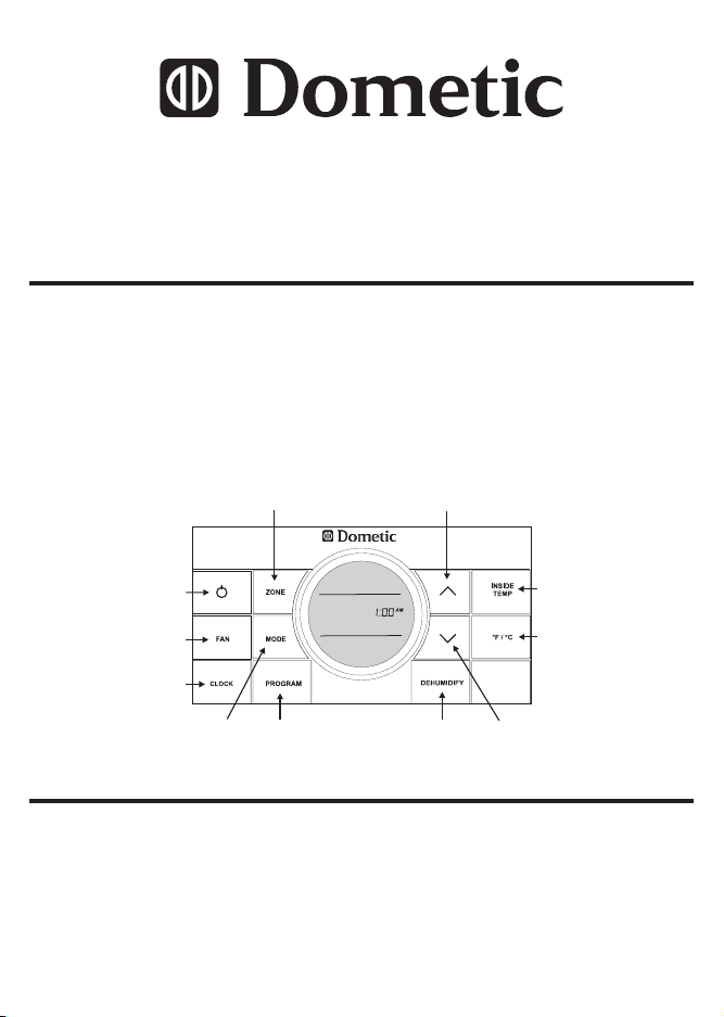
Quick reference to control buttons
Press to increase temperature
Press to select zone
or humidity set-point
Press to select
On and OFF
Press to select fan
speed
Press to set
clock
Press to
select mode
USA
SERVICE OFFICE
Dometic, LLC
2320 Industrial Parkway
Elkhart, IN 46516
574-294-2511
Press to select
program 1 or 2
Dometic, LLC
46 Zatonski, Unit 3
Brantford, ON N3T 5L8
519-720-9578
Press to display
relative humidity setpoint (Select Models)
CANADA
CANADA
Press to display
inside temperature
Press to select
temperature format
Press to decrease
temperature or
humidity set-point
For Service Center
Assistance Call:
800-544-4881
Form No. 3314150.016 10/11
(Replaces 3314150.000)
(French 3314170.014)
REVISION
©2011 Dometic, LLC
LaGrange, IN 46761
Page 2
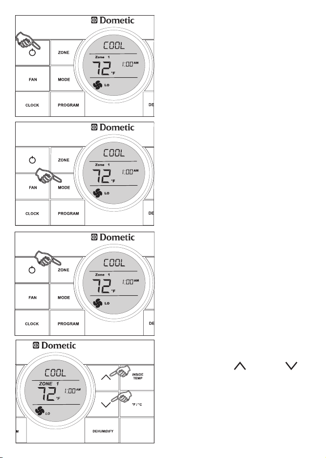
1. To turn ON the CCC 2 thermostat
when the back light is off, rst press
any button to wake up the CCC 2
thermostat. Then press and release
the ON/OFF button.
2. Press the MODE button to cycle
through the mode options. A mode is
an operation that can be performed
by the unit and is controlled by
the Dometic CCC thermostat. The
available modes are: OFF, COOL,
HP (HEAT PUMP), HS (Heat Strip),
FAN, FURN (Furnace), and AUTO.
The available modes are determined
by your system options.
3. Press the ZONE button to cycle
through the available zones to be
programmed. Each zone signies a
unit designated to cool, heat or de-
humidify a specic area of an RV.
The Dometic CCC 2 thermostat can
control up to four units (zones).
4. Press the UP or DOWN buttons to increase or decrease the room
air temperature (hereinafter referred
to as the set-point). The set-point
is the desired inside room air temperature.
Page 3

5. Press the FAN button to select the
fan speed. The options are AUTO, HI,
MED, or LO.
6. Press the CLOCK button to initiate
the clock setting sub-menu on the
CCC 2 thermostat. When entering
this menu, the “hour” digits will ash
rst. Press the CLOCK button again
and the “minutes” digits will ash.
Press it a third time and the “AM” or
“PM” icon will ash.
Press the UP and DOWN buttons to set the “hour”, “minute”, and
“AM/PM” setting.
Press the CLOCK button one more
time to store the new time in memory
and exit the clock setting sub-menu.
7. Press and hold the INSIDE TEMP
button and the LCD will display the
current inside temperature recorded
at the CCC 2 Thermostat (or at the
optional remote indoor temperature
sensor) instead of the temperature
set-point. The LCD will also display
“IN” to indicate that the inside temperature is being displayed. When the
INSIDE TEMP button is released, the
LCD will return to the programmed
temperature set-point.
Page 4

Special Features:
● Auto Fan
● Stage Select (Two air conditioners/
heat pumps or models equipped with
two compressors)
● Programs 1 & 2
● Auxiliary Heat (heat pump models
only)
● Load Shed
● Automatic Generator Start (optional)
See Operating Instructions Manual
for more information on special feature.
LCD Error Code
When the system determines that one of
the faults listed below has occurred an
error code will be displayed in the LCD
for the zone in which the error occurred.
During normal operation, a blinking zone
number indicates a fault has occurred.
The error code is displayed in place of the
temperature set-point.
E3 Shorted Indoor Temperature Sensor.
All heat, cool, and dehumidify operation will be locked out. Manual fan operation can continue.
E4 Open circuit or out of range Outdoor
Temperature Sensor (Select Models).
Heat pump and dehumidication op-
eration will be locked out. Air conditioner, furnace, heat strip, and fan operation can continue to operate.
E5 Open circuit or out of range Freeze
Sensor (Select Models). Air conditioner and dehumidication operation will
be locked out. Heat pump, furnace,
heat strip, and fan operation can continue to operate but displays the last
temperature set-point.
E6 Open circuit Humidity Sensor (Select
Models). Air conditioner and dehu-
midication operation will be locked
out. Heat pump, furnace, heat strip,
and fan can continue to operate.
E7 Loss of 120 VAC power to all power
module boards on the system. The
system will shut down.
Error Code:
E1 Loss of communication between the
CCC 2 thermostat and all system
power module boards. System will
shut down.
E1 Loss of communication between the
CCC 2 thermostat and an individual
system power module board. The
LED will display error code E1 and
the zone number that lost communication. Any additional zones that lose
communication will blink in addition to
the current zone.
E8 Invalid zone conguration. The heat
pump and heat strip DIP switches
are both set to the ON position in one
zone. Heat pump, heat strip, air conditioner, and dehumidify operation
will be locked out in the affected zone.
E9 Invalid zone conguration. The dehu-
midier DIP switch and either the heat
pump or heat strip DIP switches are
set to the ON position in one zone.
Heat pump, heat strip, air conditioner, and dehumidify operation will be
locked out in the affected zone.
E2 Open circuit or out-of-range Indoor
Temperature Sensor. All heat, cool,
and dehumidify operation will be
locked out. Manual fan operation can
continue.
In the unlikely event you experience a system failure, refer to the “SERVICE” section of the Operating
Instructions furnished with your unit.
 Loading...