

Page 1
ENDEFR
ESPTITNLDASVNO
FIRUPLSKCS
HU
DRIVING SUPPORT
PERFECTVIEW
Ryggevideokamera
Monterings- og bruksanvisning . . . . . . . 78
Peruutusvideokamera
Asennus- ja käyttöohje. . . . . . . . . . . . . . . 86
Видеокамера заднего вида
Инструкция по монтажу
и эксплуатации. . . . . . . . . . . . . . . . . . . . . 94
Kamera cofania
Instrukcja montażu i obsługi . . . . . . . . . 102
CAM29S
Rear View Video Camera
Installation and Operating Manual . . . . . . 6
Rückfahrvideokamera
Montage- und Bedienungsanleitung . . . 14
Caméra vidéo de recul
Instructions de montage
et de service . . . . . . . . . . . . . . . . . . . . . . . 22
Cámara de vídeo de marcha atrás
Instrucciones de montaje y de uso . . . . . 30
Câmara de marcha-atrás
Instruções de montagem e manual de
instruções . . . . . . . . . . . . . . . . . . . . . . . . . 38
Videocamera per la retromarcia
Istruzioni di montaggio e d’uso . . . . . . . .46
Achteruitrijvideocamera
Montagehandleiding en
gebruiksaanwijzing. . . . . . . . . . . . . . . . . . 54
Cúvacia kamera
Návod na montáž a uvedenie
do prevádzky . . . . . . . . . . . . . . . . . . . . . .110
Couvací kamera
Návod k montáži a obsluze . . . . . . . . . . .118
Tolatókamera
Szerelési és használati útmutató . . . . . . 126
Bakvideokamera
Monterings- og betjeningsvejledning. . . 62
Backningsvideokamera
Monterings- och bruksanvisning . . . . . . . 70
Page 2

Page 3
CAM29S
1
2
3
Page 4
CAM29S
1 2
3
4
1.
2.
3.
4
Page 5
CAM29S
A
B
5
23
4 5
1
max. 110°
6
5
Page 6

Explanation of symbols CAM29S
EN
Please read this manual carefully before installing and starting up and store it in a safe
place. If the device is resold, this manual must be handed over to the purchaser.
Table of contents
1 Explanation of symbols. . . . . . . . . . . . . . . . . . . . . . . . . . . . . . . . . . . . . . . . . . . . . . . . . . . . . . . 6
2 Safety and installation instructions . . . . . . . . . . . . . . . . . . . . . . . . . . . . . . . . . . . . . . . . . . . . . .7
3 Scope of delivery . . . . . . . . . . . . . . . . . . . . . . . . . . . . . . . . . . . . . . . . . . . . . . . . . . . . . . . . . . .8
4 Accessories/expansions . . . . . . . . . . . . . . . . . . . . . . . . . . . . . . . . . . . . . . . . . . . . . . . . . . . . .8
5 Intended use . . . . . . . . . . . . . . . . . . . . . . . . . . . . . . . . . . . . . . . . . . . . . . . . . . . . . . . . . . . . . . .8
6 Technical description . . . . . . . . . . . . . . . . . . . . . . . . . . . . . . . . . . . . . . . . . . . . . . . . . . . . . . . . 8
7 Installing the reversing video camera . . . . . . . . . . . . . . . . . . . . . . . . . . . . . . . . . . . . . . . . . . . 9
9 Connecting electrical power to the reversing video camera . . . . . . . . . . . . . . . . . . . . . . . . 11
10 Checking the function and setting the camera . . . . . . . . . . . . . . . . . . . . . . . . . . . . . . . . . . . 11
11 Maintaining and cleaning the reversing video camera . . . . . . . . . . . . . . . . . . . . . . . . . . . . . 12
12 Troubleshooting . . . . . . . . . . . . . . . . . . . . . . . . . . . . . . . . . . . . . . . . . . . . . . . . . . . . . . . . . . . 12
13 Warranty . . . . . . . . . . . . . . . . . . . . . . . . . . . . . . . . . . . . . . . . . . . . . . . . . . . . . . . . . . . . . . . . . 12
14 Disposal. . . . . . . . . . . . . . . . . . . . . . . . . . . . . . . . . . . . . . . . . . . . . . . . . . . . . . . . . . . . . . . . . . 12
15 Technical data. . . . . . . . . . . . . . . . . . . . . . . . . . . . . . . . . . . . . . . . . . . . . . . . . . . . . . . . . . . . . 13
1 Explanation of symbols
CAUTION!
!
A
Safety instruction: Failure to observe this instruction can lead to injury.
NOTICE!
Failure to observe this instruction can cause material damage and impair the function
of the product.
NOTE
I
6
Supplementary information for operating the product.
Page 7

CAM29S Safety and installation instructions
EN
2 Safety and installation instructions
The manufacturer accepts no liability for damage in the following cases:
• Faulty assembly or connection
• Damage to the product resulting from mechanical influences and excess voltage
• Alterations to the product without express permission from the manufacturer
• Use for purposes other than those described in the operating manual
Please observe the prescribed safety instructions and stipulations from the vehicle
manufacturer and service workshops.
Observe the following installation instructions:
CAUTION!
!
A
Observe the following instructions when working with electrical parts:
A
• Secure the parts installed in the vehicle to ensure they cannot become loose under
any circumstances (sudden braking, accidents) and cause injuries to vehicle occupants.
• Always follow the safety instructions of the vehicle manufacturer.
Some work (e.g. on retention systems such as the AIRBAG etc.) may only be performed by qualified specialists.
NOTICE!
• To prevent damage when drilling, make sure there is sufficient space on the other
side for the drill head to emerge.
• Deburr all drill holes and treat them with a rust-protection agent.
NOTICE!
• When testing the voltage in electrical cables, only use a diode test lamp or a voltmeter.
Test lamps with a bulb consume too much voltage, which can damage the vehicle's
electronic system.
• When making electrical connections, ensure that:
– they are not kinked or twisted
– they do not rub on edges
– they are not laid in sharp-edged ducts without protection.
• Insulate all connections.
• Secure the cables against mechanical wear by using cable binders or insulating tape,
for example on existing cables.
7
Page 8

Scope of delivery CAM29S
EN
The camera is waterproof, however, you should observe the following instructions when handling
the camera:
NOTICE!
A
• Do not spray the camera directly with a high-pressure cleaning device.
• Do not open the camera or pull at the cables, as this impairs the leak-tightness and
the function of the camera.
• The camera is not suitable for use under water.
3Scope of delivery
No. in
fig. 3, page 4
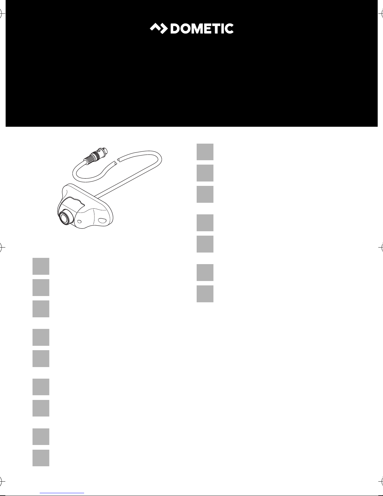
1 1 Camera 9600000199
2 1 Connection cable 20 m long
——Fastening material
4 Accessories/expansions
Quantity Description Reference no.
Description Item no.
Extension cable, 5 m 9103555986
Extension cable, 20 m 9103555670
5Intended use
The CAM 29S (reference no. 9600000199) is suitable for reversing video systems used in vehicles.
Reversing video systems support the driver when reversing, however this does not relieve you of
the obligation to take proper care when reversing.
6 Technical description
The CAM29S camera can be used in various ways, for example, as a reversing video camera for
installing on the outside of vehicles.
The electrical connection takes place using a cable ready to plug into the monitor.
8
Page 9

CAM29S Installing the reversing video camera
EN
7 Installing the reversing video camera
NOTE
I
7.1 Fitting the camera
Observe the following information when selecting an installation location for the camera:
• Note the length of the camera cable.
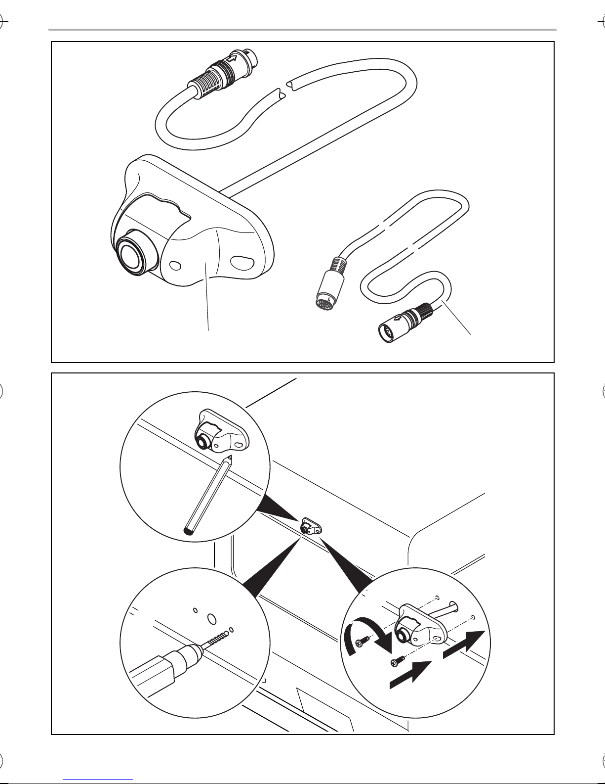
• If you wish to use the camera as a reversing video camera, installing the camera on the top
middle of the vehicle bumper is recommended (fig. 4, page 4).
The installation location should be sufficiently firm (e.g. to prevent the camera from being
knocked down by branches that may brush the roof of the vehicle).
➤ Select a suitable installation location.
If you do not have sufficient technical knowledge to install and connect the
components in vehicles, have a specialist install the reversing video camera in your
vehicle.
NOTICE!
A
➤ Install the camera in accordance with fig. 4, page 4.
I
➤ Check that the camera is installed securely.
Before drilling any holes, ensure that no electrical cables or other parts of the vehicle
can be damaged by drilling, sawing and filing.
NOTE
Make sure it is correctly aligned. If the camera is not correctly aligned, the picture will
be askew or upside down on the monitor.
9
Page 10

Laying cables CAM29S
EN
8 Laying cables
NOTICE!
A
I
Therefore, please observe the following instructions:
• Wherever possible, lay cables inside the vehicle, as they are better protected there than
outside.
If you do need to lay a cable outside the vehicle, ensure that it is well fastened (use additional
cable ties, insulating tape etc.).
Before drilling any holes, ensure that no electrical cables or other parts of the vehicle
can be damaged by drilling, sawing and filing.
NOTE
• As far as possible, use original ducts for laying the cables, or other suitable options
such as panelling edges, ventilation grilles or dummy plugs. If there is no rubber
plug, produce a suitable hole with a diameter of around 13 mm and insert a cable
bushing sleeve.
• Cables and connections that are not properly installed will cause malfunctions or
damage to components. Correct installation of cables and connections ensures
lasting and trouble-free operation of the retrofitted components.
• To prevent damage to the cables when laying them, ensure that they are far enough away from
hot or moving vehicle components (exhaust pipes, drive shafts, light systems, fans, heaters,
etc.).
• Wrap good-quality insulating tape around the plug connections of the connecting cables and
every connection on a cable (including inside the vehicle) to ensure no water can penetrate
them (fig. 5 B, page 5). The most suitable tape for this is self-vulcanising tape, e.g. made by
3M.
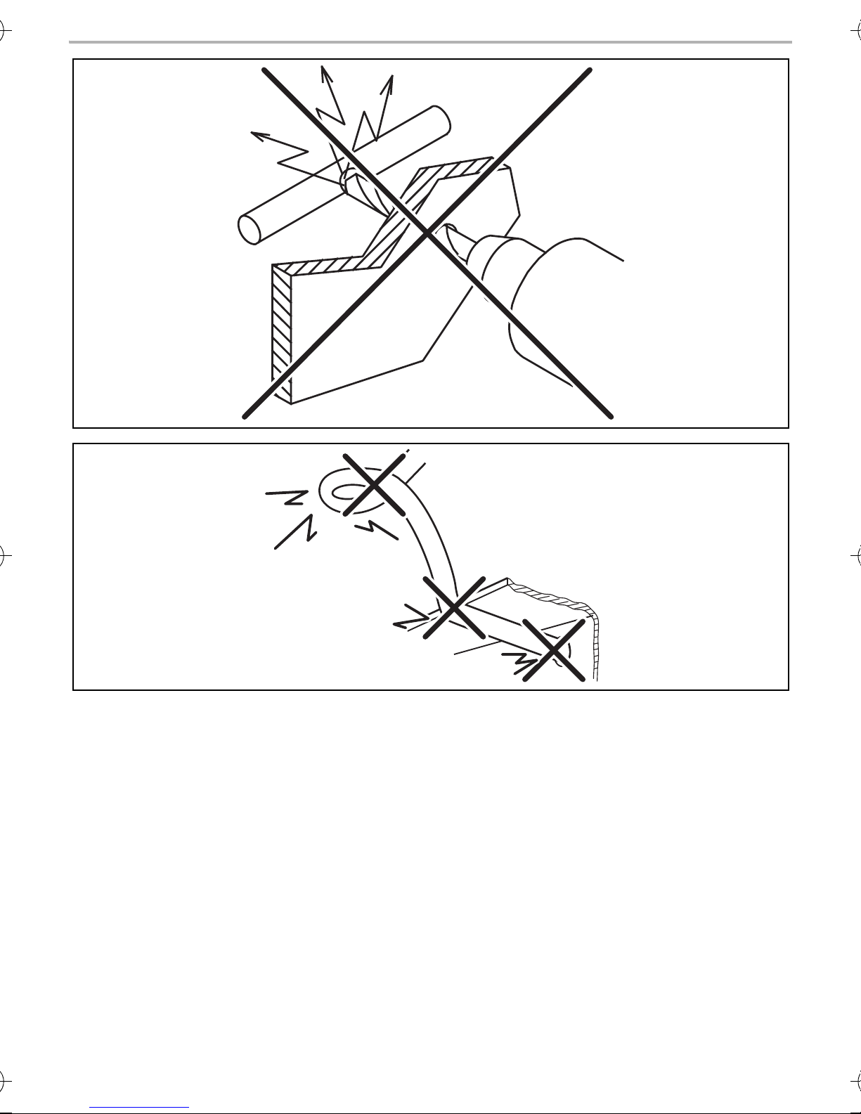
• When laying the cables, make sure:
– they are not kinked or twisted
– they do not rub on edges
– they are not laid in sharp-edged ducts without protection (fig. 2, page 3).
• Attach the cables securely in the vehicle with cable binders, insulating tape or by glueing them
to prevent them from being tripped over.
• Protect every through-hole made in the outer skin of the bodywork against water penetration,
for example by using a cable with a sealant and by spraying the cable and the cable sleeve with
sealant.
NOTE
I
• Only start sealing through-holes when you have completed all installation work on
the camera and have laid the required cable lengths.
• Pull the socket connector of the camera cable through the cable bushing sleeve
before inserting the sleeve in the bodywork.
10
Page 11

CAM29S Connecting electrical power to the reversing video camera
EN
➤ Route the camera cable into the interior of the vehicle so that it cannot be damaged under any
circumstances (e.g. by gravel impact).
➤ Lay the camera cable so that should you need to remove the camera, you can easily access the
plug connection.
9 Connecting electrical power to the reversing video camera
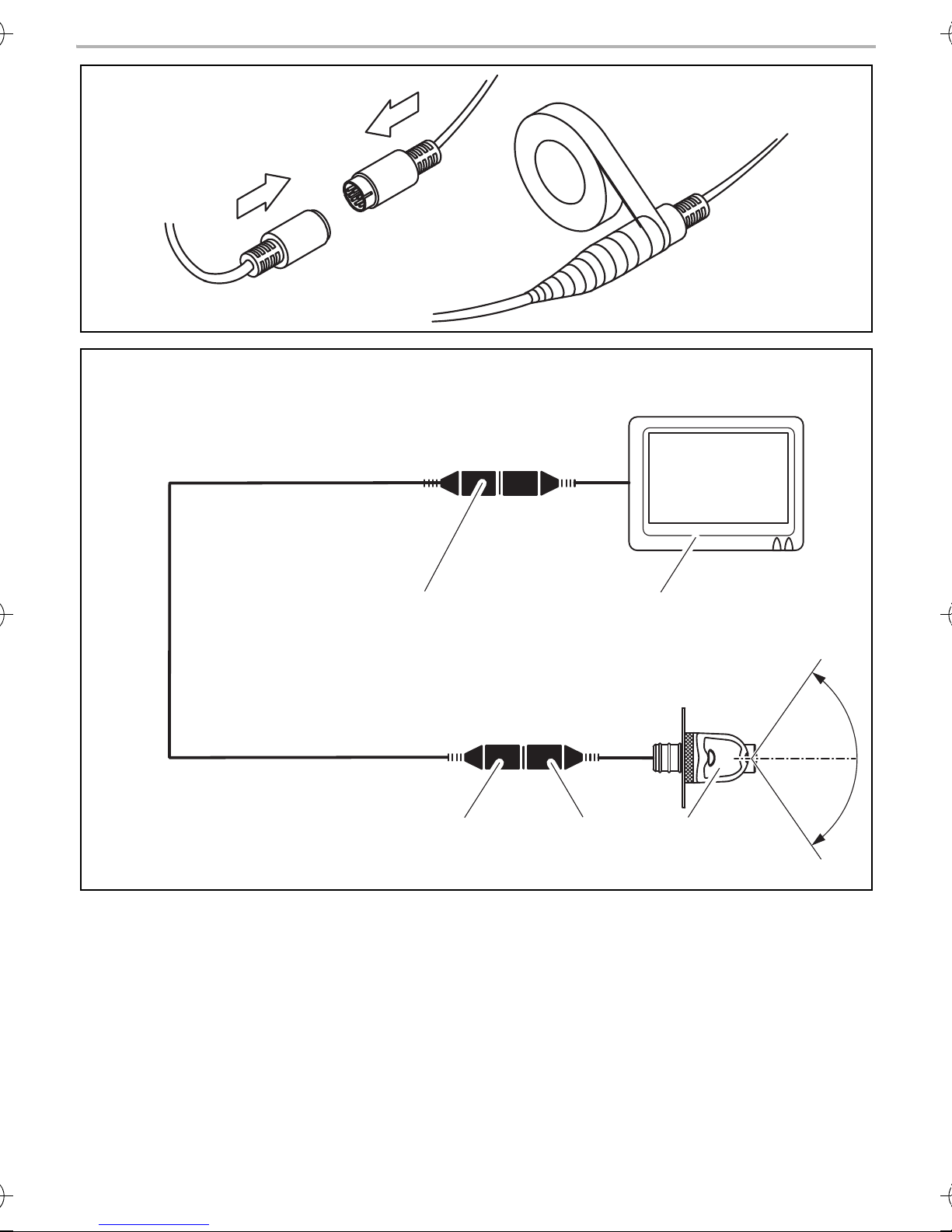
The circuit diagram for the reversing video camera can be found in fig. 6, page 5.
No. in
fig. 6, page 5
1Camera
26-pin mini DIN plug
36-pin mini DIN socket
46-pin plug
5 Monitor with 6-pin socket
Connecting the camera
NOTE
I
➤ Insert the plug of the camera cable (fig. 6 2, page 5) as far as it will go into the 6-pin socket
(fig. 6 3, page 5) of the connection cable.
Ensure that the plastic cap of the socket reaches up to the arrow on the plug.
Make sure the plug connections are assembled in such a way that the arrows on the
plug and the socket are pointing at each other.
Description
➤ Connect the 6-pin plug (fig. 6 4, page 5) of the connection cable to the monitor.
10 Checking the function and setting the camera
➤ Check the function of the camera after you have connected it to a monitor.
➤ Use the monitor picture to align the camera if necessary so that the picture on the monitor is
horizontal.
11
Page 12

Maintaining and cleaning the reversing video camera CAM29S
EN
11 Maintaining and cleaning the reversing video camera
NOTICE!
A
➤ Occasionally clean the product with a damp cloth.
Do not use sharp or hard objects or cleaning agents for cleaning as these may damage
the product.
12 Troubleshooting
The monitor ceases to display camera images.
The camera or the monitor may not be properly connected.
➤ Check all plug connections between the camera and the monitor.
➤ Make sure that the monitor is supplied with power.
13 Warranty
The statutory warranty period applies. If the product is defective, please contact the
manufacturer's branch in your country (see the back of the instruction manual for the addresses) or
your retailer.
For repair and guarantee processing, please include the following documents when you send in
the device:
• A copy of the receipt with purchasing date
• A reason for the claim or description of the fault
14 Disposal
➤ Place the packaging material in the appropriate recycling waste bins wherever possible.
If you wish to finally dispose of the product, ask your local recycling centre or specialist
dealer for details about how to do this in accordance with the applicable disposal
M
regulations.
12
Page 13

CAM29S Technical data
EN
15 Technical data
CAM29S
Reference no. 9600000199
Operating voltage: 12 Vg
Current: 60 mA
Image sensor: ¼" CMOS sensor
Preset mirror image function
Lens: 160° opening angle, diagonal
Pixels: 640 (H) x 480 (V) (307000 pixels)
Light sensitivity: 0.5 lux
Operating temperature: –20 °C to +70 °C
Horizontal picture angle: approx. 130°
Vertical picture angle: approx. 100°
Protection class: Equivalent to IP68
Dimensions (W x H x D): 76 x 29 x 33 mm
Weight: 80 g
Certifications:
13
13
Page 14

Erklärung der Symbole CAM29S
DE
Bitte lesen Sie diese Anleitung vor Einbau und Inbetriebnahme sorgfältig durch und
bewahren Sie sie auf. Geben Sie sie im Falle einer Weiterveräußerung des Systems an
den Käufer weiter.
Inhaltsverzeichnis
1 Erklärung der Symbole . . . . . . . . . . . . . . . . . . . . . . . . . . . . . . . . . . . . . . . . . . . . . . . . . . . . . . 14
2 Sicherheits- und Einbauhinweise. . . . . . . . . . . . . . . . . . . . . . . . . . . . . . . . . . . . . . . . . . . . . . 15
3 Lieferumfang . . . . . . . . . . . . . . . . . . . . . . . . . . . . . . . . . . . . . . . . . . . . . . . . . . . . . . . . . . . . . . 16
4 Zubehör/Erweiterungen . . . . . . . . . . . . . . . . . . . . . . . . . . . . . . . . . . . . . . . . . . . . . . . . . . . . 16
5 Bestimmungsgemäßer Gebrauch . . . . . . . . . . . . . . . . . . . . . . . . . . . . . . . . . . . . . . . . . . . . . 16
6 Technische Beschreibung . . . . . . . . . . . . . . . . . . . . . . . . . . . . . . . . . . . . . . . . . . . . . . . . . . . 16
7 Rückfahrvideokamera montieren . . . . . . . . . . . . . . . . . . . . . . . . . . . . . . . . . . . . . . . . . . . . . . 17
8 Rückfahrvideokamera elektrisch anschließen . . . . . . . . . . . . . . . . . . . . . . . . . . . . . . . . . . . . 19
9 Funktion prüfen und Kamera einstellen . . . . . . . . . . . . . . . . . . . . . . . . . . . . . . . . . . . . . . . . .20
10 Rückfahrvideokamera pflegen und reinigen . . . . . . . . . . . . . . . . . . . . . . . . . . . . . . . . . . . . .20
11 Fehler suchen . . . . . . . . . . . . . . . . . . . . . . . . . . . . . . . . . . . . . . . . . . . . . . . . . . . . . . . . . . . . .20
12 Gewährleistung . . . . . . . . . . . . . . . . . . . . . . . . . . . . . . . . . . . . . . . . . . . . . . . . . . . . . . . . . . .20
13 Entsorgung . . . . . . . . . . . . . . . . . . . . . . . . . . . . . . . . . . . . . . . . . . . . . . . . . . . . . . . . . . . . . . .20
14 Technische Daten . . . . . . . . . . . . . . . . . . . . . . . . . . . . . . . . . . . . . . . . . . . . . . . . . . . . . . . . . . 21
1 Erklärung der Symbole
VORSICHT!
!
A
Sicherheitshinweis: Nichtbeachtung kann zu Verletzungen führen.
ACHTUNG!
Nichtbeachtung kann zu Materialschäden führen und die Funktion des Produktes
beeinträchtigen.
HINWEIS
I
14
Ergänzende Informationen zur Bedienung des Produktes.
Page 15

CAM29S Sicherheits- und Einbauhinweise
DE
2 Sicherheits- und Einbauhinweise
Der Hersteller übernimmt in folgenden Fällen keine Haftung für Schäden:
• Montage- oder Anschlussfehler
• Beschädigungen am Produkt durch mechanische Einflüsse und Überspannungen
• Veränderungen am Produkt ohne ausdrückliche Genehmigung vom Hersteller
• Verwendung für andere als die in der Anleitung beschriebenen Zwecke
Beachten Sie die vom Fahrzeughersteller und vom Kfz-Handwerk vorgeschriebenen
Sicherheitshinweise und Auflagen!
Beachten Sie folgende Hinweise bei der Montage:
VORSICHT!
!
A
Beachten Sie folgende Hinweise bei der Arbeit an elektrischen Teilen:
A
• Befestigen Sie die im Fahrzeug montierten Teile so, dass sie sich unter keinen
Umständen (scharfes Abbremsen, Verkehrsunfall) lösen und zu Verletzungen der
Fahrzeuginsassen führen können.
• Beachten Sie immer die Sicherheitshinweise des Fahrzeugherstellers.
Einige Arbeiten (z. B. an Rückhaltesystemen wie Airbag usw.) dürfen nur von geschultem Fachpersonal durchgeführt werden.
ACHTUNG!
• Achten Sie beim Bohren auf ausreichenden Freiraum für den Bohreraustritt, um Schäden zu vermeiden.
• Entgraten Sie jede Bohrung und behandeln Sie diese mit Rostschutzmittel.
ACHTUNG!
• Benutzen Sie zum Prüfen der Spannung in elektrischen Leitungen nur eine Diodenprüflampe oder ein Voltmeter.
Prüflampen mit einem Leuchtkörper nehmen zu hohe Ströme auf, wodurch die Fahrzeugelektronik beschädigt werden kann.
• Beachten Sie beim Verlegen der elektrischen Anschlüsse, dass diese
– nicht geknickt oder verdreht werden,
– nicht an Kanten scheuern,
– nicht ohne Schutz durch scharfkantige Durchführungen verlegt werden.
• Isolieren Sie alle Verbindungen und Anschlüsse.
• Sichern Sie die Kabel gegen mechanische Beanspruchung durch Kabelbinder oder
Isolierband, z. B. an vorhandenen Leitungen.
15
Page 16

Lieferumfang CAM29S
DE
Die Kamera ist wasserdicht, beachten Sie aber trotzdem folgende Hinweise zum Umgang mit der
Kamera:
ACHTUNG!
A
• Setzen Sie die Kamera niemals direkt dem Strahl eines Hochdruckreinigers aus.
• Öffnen Sie die Kamera nicht und ziehen Sie nicht an den Kabeln, da dieses die
Dichtigkeit und die Funktionsfähigkeit der Kamera beeinträchtigt.
• Die Kamera ist nicht für den Betrieb unter Wasser geeignet!
3Lieferumfang
Nr. in Abb. 3,
Seite 4
1 1 Kamera 9600000199
2 1 Anschlusskabel, 20 m lang
––Befestigungsmaterial
4 Zubehör/Erweiterungen
Menge Bezeichnung Artikel-Nr.
Bezeichnung Artikel-Nr.
Verlängerungskabel 5 m 9103555986
Verlängerungskabel 20 m 9103555670
5 Bestimmungsgemäßer Gebrauch
Die Kamera CAM 29S (Art.-Nr. 9600000199) eignet sich für Rückfahrvideosysteme zum Gebrauch
in Fahrzeugen.
Rückfahrvideosysteme stellen eine Unterstützung beim Rückwärtsfahren dar, entbinden Sie
jedoch nicht von der besonderen Vorsichtspflicht beim Rückwärtsfahren.
6 Technische Beschreibung
Die Kamera CAM 29S kann sehr vielseitig eingesetzt werden, z. B. als Rückfahrvideokamera für die
Außenmontage an Fahrzeugen.
Der elektrische Anschluss erfolgt über ein steckfertig vorbereitetes Kabel an den Monitor.
16
Page 17

CAM29S Rückfahrvideokamera montieren
DE
7 Rückfahrvideokamera montieren
HINWEIS
I
7.1 K amera montieren
Berücksichtigen Sie folgende Hinweise bei der Auswahl des Montageortes für die Kamera:
• Beachten Sie die Länge des Kamerakabels.
• Wenn Sie die Kamera als Rückfahrvideokamera einsetzen wollen, empfiehlt sich ein Einbau in
der oberen Mitte des Fahrzeughecks (Abb. 4, Seite 4).
Der Montageort sollte eine ausreichende Festigkeit bieten (z. B. können sich über das Fahrzeugdach streifende Äste in der Kamera verfangen).
➤ Wählen Sie einen geeigneten Montageort.
Wenn Sie nicht über ausreichende technische Kenntnisse für das Einbauen und
Anschließen von Komponenten in Fahrzeugen verfügen, lassen Sie sich die Rückfahrvideokamera von einem Fachmann ins Fahrzeug einbauen.
ACHTUNG!
A
➤ Montieren Sie die Kamera gemäß Abb. 4, Seite 4.
I
➤ Prüfen Sie den festen Sitz der Kamera.
Bevor Sie irgendwelche Bohrungen vornehmen, stellen Sie sicher, dass keine elektrischen Kabel oder andere Teile des Fahrzeuges durch Bohren, Sägen und Feilen
beschädigt werden.
HINWEIS
Achten Sie auf die korrekte Ausrichtung. Wird die Kamera nicht korrekt ausgerichtet,
so wird das Bild schief oder auf dem Kopf am Monitor angezeigt.
17
Page 18

Rückfahrvideokamera montieren CAM29S
DE
7.2 Kabel verlegen
ACHTUNG!
A
I
Bevor Sie irgendwelche Bohrungen vornehmen, stellen Sie sicher, dass keine elektrischen Kabel oder andere Teile des Fahrzeuges durch Bohren, Sägen und Feilen
beschädigt werden.
HINWEIS
• Verwenden Sie für die Durchführung der Anschlusskabel nach Möglichkeit
Originaldurchführungen oder andere Durchführungsmöglichkeiten, z. B. Verkleidungskanten, Lüftungsgitter oder Blindschalter. Wenn kein Gummistopfen vorhanden ist, fertigen Sie eine entsprechende Bohrung von ca. Ø 13 mm an, und setzen
Sie eine Kabeldurchführungstülle ein.
• Nicht fachgerechte Kabelverlegungen und Kabelverbindungen führen immer wieder zu Fehlfunktionen oder Beschädigungen von Bauteilen. Eine korrekte Kabelverlegung bzw. Kabelverbindung ist die Grundvoraussetzung für eine dauerhafte und
fehlerfreie Funktion der nachgerüsteten Komponenten.
Beachten Sie deshalb folgende Hinweise:
• Verlegen Sie die Kabel nach Möglichkeit immer im Fahrzeuginneren, denn dort sind sie besser
geschützt als außen am Fahrzeug.
Wenn Sie die Kabel trotzdem außerhalb des Fahrzeuges verlegen, achten Sie auf eine sichere
Befestigung (durch zusätzliche Kabelbinder, Isolierband usw.).
• Um Beschädigungen am Kabel zu vermeiden, halten Sie beim Verlegen der Kabel immer ausreichend Abstand zu heißen und sich bewegenden Fahrzeugteilen (Auspuffrohre, Antriebswellen, Lichtmaschine, Lüfter, Heizung usw.).
• Umwickeln Sie die Steckverbindungen der Verbindungskabel zum Schutz gegen das Eindringen von Wasser und jede Verbindung an einem Kabel (auch im Fahrzeug) dicht mit einem
guten Isolierband (Abb. 5 B, Seite 5). Am besten eignet sich selbstvulkanisierendes Dichtband, z. B. von 3M.
• Beachten Sie beim Verlegen der Kabel, dass diese
– nicht stark geknickt oder verdreht werden,
–nicht an Kanten scheuern,
– nicht ohne Schutz durch scharfkantige Durchführungen verlegt werden (Abb. 2, Seite 3).
• Befestigen Sie die Kabel sicher im Fahrzeug mit Kabelbindern, Isolierband oder durch Ankleben mit Klebstoff, um ein Verfangen (Sturzgefahr) zu vermeiden.
• Schützen Sie jeden Durchbruch an der Außenhaut der Karosserie durch geeignete Maßnahmen gegen Wassereinbruch, z. B. durch Einsetzen des Kabels mit Dichtungsmasse und durch
Abspritzen des Kabels und der Durchführungstülle mit Dichtungsmasse.
18
Page 19

CAM29S Rückfahrvideokamera elektrisch anschließen
DE
HINWEIS
I
➤ Verlegen Sie das Kamerakabel so ins Fahrzeuginnere, dass es unter keinen Umständen
beschädigt werden kann (z. B. durch Steinschlag).
➤ Verlegen Sie das Kamerakabel so, dass Sie bei einer eventuell notwendigen Demontage der
Kamera leicht an die Steckverbindung kommen.
• Beginnen Sie mit dem Abdichten der Durchbrüche erst, nachdem alle Einstellarbeiten an der Kamera abgeschlossen sind und die benötigten Längen der Anschlusskabel festliegen.
• Ziehen Sie die Steckbuchse des Kamerakabels durch die Kabeldurchführungstülle,
bevor Sie die Tülle in die Karosserie einsetzen.
8 Rückfahrvideokamera elektrisch anschließen
Den Schaltplan für die Rückfahrvideokamera finden Sie in Abb. 6, Seite 5.
Nr. in
Abb. 6, Seite 5
1Kamera
2 6-poliger Mini-DIN-Stecker
3 6-polige Mini-DIN-Buchse
4 6-poliger Stecker
5 Monitor mit 6-poliger Buchse
Kamera anschließen
HINWEIS
I
➤ Stecken Sie den Stecker des Kamerakabels (Abb. 6 2, Seite 5) bis zum Anschlag in die 6-
polige Buchse (Abb. 6 3, Seite 5) des Anschlusskabels.
Achten Sie darauf, dass die Plastikkappe der Buchse bis an den Pfeil auf dem Stecker reicht.
Achten Sie darauf, dass Sie die Steckverbindung so zusammensetzen, dass die Pfeile
auf Stecker und Steckbuchse zueinander weisen.
Bezeichnung
➤ Schließen Sie den 6-poligen Stecker (Abb. 6 4, Seite 5) des Anschlusskabels an den Moni-
tor an.
19
Page 20

Funktion prüfen und Kamera einstellen CAM29S
DE
9 Funktion prüfen und Kamera einstellen
➤ Prüfen Sie die Funktion der Kamera, nachdem Sie sie an einen Monitor angeschlossen haben.
➤ Richten Sie die Kamera gegebenenfalls anhand des Monitorbildes aus, sodass das Bild auf
dem Monitor waagerecht angezeigt wird.
10 Rückfahrvideokamera pflegen und reinigen
ACHTUNG!
A
➤ Reinigen Sie das Produkt gelegentlich mit einem feuchten Tuch.
Keine scharfen oder harten Gegenstände oder Reinigungsmittel zur Reinigung ver-
wenden, da dies zu einer Beschädigung des Produktes führen kann.
11 Fehler suchen
Der Monitor zeigt keine Bilder der Kamera an.
Die Kamera oder der Monitor sind möglicherweise nicht korrekt angeschlossen.
➤ Prüfen Sie sämtliche Steckverbindungen zwischen Kamera und Monitor.
➤ Stellen Sie sicher, dass der Monitor mit Spannung versorgt wird.
12 Gewährleistung
Es gilt die gesetzliche Gewährleistungsfrist. Sollte das Produkt defekt sein, wenden Sie sich bitte
an die Niederlassung des Herstellers in Ihrem Land (Adressen siehe Rückseite der Anleitung) oder
an Ihren Fachhändler.
Zur Reparatur- bzw. Gewährleistungsbearbeitung müssen Sie folgende Unterlagen mitschicken:
• eine Kopie der Rechnung mit Kaufdatum,
• einen Reklamationsgrund oder eine Fehlerbeschreibung.
13 Entsorgung
➤ Geben Sie das Verpackungsmaterial möglichst in den entsprechenden Recycling-Müll.
Wenn Sie das Produkt endgültig außer Betrieb nehmen, informieren Sie sich bitte beim
nächsten Recyclingcenter oder bei Ihrem Fachhändler über die zutreffenden
M
20
Entsorgungsvorschriften.
Page 21

CAM29S Technische Daten
DE
14 Technische Daten
CAM29S
Artikel-Nr.: 9600000199
Betriebsspannung: 12 Vg
Stromaufnahme: 60 mA
Bildsensor: ¼" CMOS Sensor
Spiegelfunktion voreingestellt
Objektiv: 160° Öffnungswinkel, diagonal
Bildpunkte: 640 (H) x 480 (V) (307000 Pixel)
Lichtempfindlichkeit: 0,5 Lux
Betriebstemperatur: –20 °C bis +70 °C
Bildwinkel horizontal: ca. 130°
Bildwinkel vertikal: ca. 100°
Schutzklasse: äquivalent IP68
Abmessungen (B x H x T): 76 x 29 x 33 mm
Gewicht: 80 g
Zulassungen:
13
21
Page 22

Explication des symboles CAM29S
FR
Veuillez lire ce manuel avec attention avant le montage et la mise en service, puis le
conserver. Transmettez-le au nouvel acquéreur si vous revendez le système.
Sommaire
1 Explication des symboles. . . . . . . . . . . . . . . . . . . . . . . . . . . . . . . . . . . . . . . . . . . . . . . . . . . .22
2 Consignes de sécurité et instructions de montage. . . . . . . . . . . . . . . . . . . . . . . . . . . . . . . .23
3 Contenu de la livraison. . . . . . . . . . . . . . . . . . . . . . . . . . . . . . . . . . . . . . . . . . . . . . . . . . . . . .24
4 Accessoires/Extensions . . . . . . . . . . . . . . . . . . . . . . . . . . . . . . . . . . . . . . . . . . . . . . . . . . . . .24
5 Usage conforme . . . . . . . . . . . . . . . . . . . . . . . . . . . . . . . . . . . . . . . . . . . . . . . . . . . . . . . . . . .24
6 Description technique . . . . . . . . . . . . . . . . . . . . . . . . . . . . . . . . . . . . . . . . . . . . . . . . . . . . . .24
7 Montage de la caméra vidéo de recul. . . . . . . . . . . . . . . . . . . . . . . . . . . . . . . . . . . . . . . . . .25
8 Raccordement électrique de la caméra vidéo de recul . . . . . . . . . . . . . . . . . . . . . . . . . . . .27
9 Vérification du fonctionnement et réglage de la caméra . . . . . . . . . . . . . . . . . . . . . . . . . . .28
10 Entretien et nettoyage de la caméra vidéo de recul . . . . . . . . . . . . . . . . . . . . . . . . . . . . . . .28
11 Recherche de pannes. . . . . . . . . . . . . . . . . . . . . . . . . . . . . . . . . . . . . . . . . . . . . . . . . . . . . . .28
12 Garantie. . . . . . . . . . . . . . . . . . . . . . . . . . . . . . . . . . . . . . . . . . . . . . . . . . . . . . . . . . . . . . . . . .28
13 Retraitement . . . . . . . . . . . . . . . . . . . . . . . . . . . . . . . . . . . . . . . . . . . . . . . . . . . . . . . . . . . . . .28
14 Caractéristiques techniques. . . . . . . . . . . . . . . . . . . . . . . . . . . . . . . . . . . . . . . . . . . . . . . . . .29
1 Explication des symboles
ATTENTION !
!
A
Consigne de sécurité : le non-respect de ces consignes peut entraîner des blessures.
AVIS !
Le non-respect de ces consignes peut entraîner des dommages matériels et des
dysfonctionnements du produit.
REMARQUE
I
22
Informations complémentaires sur l'utilisation du produit.
Page 23

CAM29S Consignes de sécurité et instructions de montage
FR
2 Consignes de sécurité et instructions de montage
Le fabricant décline toute responsabilité pour des dommages dans les cas suivants :
• des défauts de montage ou de raccordement
• des influences mécaniques et des surtensions ayant endommagé le matériel
• des modifications apportées au produit sans autorisation explicite de la part du fabricant
• une utilisation différente de celle décrite dans la notice
Respectez les consignes de sécurité et autres prescriptions imposées par le constructeur du véhicule et par les professionnels de l’automobile !
Veuillez respecter les consignes suivantes lors du montage :
ATTENTION !
!
A
Veuillez respecter les consignes suivantes lors de travaux sur des composants électriques :
A
• Fixez les pièces installées dans le véhicule de manière à ce qu’elles ne puissent en
aucun cas se desserrer (freinage brusque, accident) et risquer de causer des blessures aux occupants du véhicule.
• Respectez toujours les consignes de sécurité du fabricant du véhicule.
Certains travaux (p. ex. au niveau des systèmes de rétention, AIRBAG, etc.) doivent
être effectués uniquement par un personnel spécialisé ayant reçu une formation correspondante.
AVIS !
• Avant de percer des trous, assurez-vous que vous disposez d’un espace suffisant de
l'autre côté du trou à percer afin que la mèche n'occasionne aucun dégât.
• Ébavurez tous les trous et protégez-les avec un enduit anticorrosif.
AVIS !
• Pour contrôler la tension dans les câbles électriques, utilisez uniquement une lampetémoin à diodes ou un voltmètre.
Les lampes étalons à corps lumineux absorbent des courants trop élevés qui pourraient endommager les systèmes électroniques du véhicule.
• Lors de l'agencement des raccords électriques, veillez à ce que ceux-ci
– ne soient ni pliés, ni tordus,
– ne frottent pas contre des arêtes,
– ne soient pas placés dans des traversées à arêtes vives sans protection.
• Isolez toutes les connexions et tous les raccords.
• Protégez les câbles contre toute contrainte mécanique en les fixant par exemple aux
lignes existantes à l'aide de serre-câbles ou de ruban vinyle.
23
Page 24

Contenu de la livraison CAM29S
FR
La caméra est étanche. Veillez cependant à respecter les consignes suivantes en la manipulant :
AVIS !
A
• Ne dirigez jamais le jet d'un nettoyeur à haute pression sur la caméra.
• N’ouvrez pas la caméra et ne tirez jamais sur les câbles, car ceci nuit à l'étanchéité et
au fonctionnement de la caméra.
• La caméra n'est pas prévue pour être utilisée dans l'eau.
3 Contenu de la livraison
N° dans
fig. 3, page 4
1 1 Caméra 9600000199
2 1 Câble de raccordement, longueur 20 m
– – Matériel de fixation
4 Accessoires/Extensions
Quantité Désignation N° d'article
Désignation N° d'article
Rallonge de câble de 5 m 9103555986
Rallonge de câble de 20 m 9103555670
5Usage conforme
La caméra CAM29S (n° d'article 9600000199) est conçue pour les systèmes vidéo de recul utilisés dans les véhicules.
Les systèmes vidéo de recul vous apportent une aide supplémentaire en marche arrière, mais ces
appareils ne vous dégagent pas du devoir de prudence qui vous incombe lorsque vous
conduisez en marche arrière.
6 Description technique
La caméra CAM29S offre de nombreuses possibilités d'utilisation, p. ex. comme caméra vidéo de
recul pour le montage en extérieur sur les véhicules.
Le raccordement électrique s'effectue en raccordant sur le moniteur un câble prêt à être connecté.
24
Page 25

CAM29S Montage de la caméra vidéo de recul
FR
7 Montage de la caméra vidéo de recul
REMARQUE
I
7.1 Montage de la c améra
Respectez les consignes suivantes lors du choix de l'emplacement de montage pour la caméra :
• Tenez compte de la longueur du câble de la caméra.
• Si vous voulez utiliser la caméra comme caméra vidéo de recul, il est recommandé de la monter
au centre de l’arrière du véhicule (fig. 4, page 4).
L’emplacement de la caméra doit lui garantir une stabilité suffisante (au cas où, par exemple,
des branches effleurant le toit resteraient accrochées à la caméra).
➤ Choisissez un lieu d'installation adéquat.
Si vos connaissances techniques en matière d'installation et de raccordement d'éléments dans un véhicule sont insuffisantes, nous vous recommandons de faire installer
la caméra vidéo de recul par un spécialiste.
AVIS !
A
➤ Montez la caméra conformément à fig. 4, page 4.
I
➤ Vérifiez que la caméra est correctement fixée.
Avant de commencer à percer, assurez-vous qu’aucun câble électrique ou autre élément du véhicule ne risque d’être endommagé par le perçage, le sciage ou le limage.
REMARQUE
Vérifiez que l'orientation est correcte. Si la caméra n'est pas correctement orientée,
l'image apparaît de travers ou sens dessus-dessous sur le moniteur.
25
Page 26

Montage de la caméra vidéo de recul CAM29S
FR
7.2 Pose des câbles
AVIS !
A
I
Veuillez respecter les consignes suivantes :
Avant de commencer à percer, assurez-vous qu’aucun câble électrique ou autre élément du véhicule ne risque d’être endommagé par le perçage, le sciage ou le limage.
REMARQUE
• Pour la pose des câbles de raccordement, utilisez si possible des passages existants
ou d'autres possibilités de passage telles que les arêtes de garnitures, grilles d'aération ou interrupteurs intégrés. Si aucun passage caoutchouté n’est disponible, percez un trou adéquat d’environ Ø 13 mm et placez une traversée de câble.
• Toute erreur de pose ou de branchement des câbles entraîne presque toujours des
dysfonctionnements ou des détériorations des composants. Une pose et un branchement corrects des câbles sont indispensables au fonctionnement durable et
fiable des composants que vous installez.
• Dans la mesure du possible, ne posez les câbles qu'à l'intérieur du véhicule. Ils y seront mieux
protégés qu'à l'extérieur.
Si vous devez malgré tout faire passer les câbles à l'extérieur du véhicule, veillez à ce qu'ils
soient solidement fixés (en utilisant des serre-fils supplémentaires, du ruban vinyle, etc.).
• Installez les câbles à une distance suffisante des éléments chauds et/ou mobiles du véhicule
(tuyaux d'échappement, arbres de transmission, dynamo, ventilateurs, chauffage, etc.) qui
pourraient les endommager.
• Enveloppez de manière étanche les fiches des câbles de raccordement, afin de les protéger
contre les infiltrations d'eau, ainsi que chaque connexion à un câble (dans le véhicule aussi)
avec un ruban isolant de qualité (fig. 5 B, page 5). L'idéal est un ruban isolant autovulcanisant,
par exemple celui de la marque 3M.
• Lors de la pose des câbles, veillez à ce que ceux-ci
– ne soient ni fortement pliés, ni tordus,
– ne frottent pas contre des arêtes,
– ne soient pas placés dans des traversées à arêtes vives sans protection (fig. 2, page 3).
• Fixez soigneusement les câbles à l'intérieur du véhicule à l'aide de serre-câbles, de ruban vinyle
ou fixez le câble avec de la colle pour éviter que quelqu'un ne trébuche dessus (risque de
chute).
• Veillez à protéger chaque trou percé dans la carrosserie en prenant des mesures appropriées
contre toute infiltration d’eau, par exemple en appliquant du mastic sur le câble et sur le passecâble.
26
Page 27

CAM29S Raccordement électrique de la caméra vidéo de recul
FR
REMARQUE
I
➤ Posez le câble de la caméra de manière à ce qu’il ne puisse en aucun cas être endommagé
(p. ex. par une chute de pierres).
➤ Posez le câble de la caméra de telle manière que la prise soit facilement accessible si un
démontage de la caméra était nécessaire.
• Les opérations d'étanchéification des ouvertures ne doivent être entreprises que
lorsque tous les réglages de position de la caméra ont été effectués et que les longueurs de câbles de raccordement nécessaires sont définies.
• Faites passer le connecteur femelle du câble de la caméra à travers le passe-câbles
avant de placer la traversée dans la carrosserie.
8 Raccordement électrique de la caméra vidéo de recul
Le schéma du circuit de la caméra vidéo de recul se trouve dans la fig. 6, page 5.
N° dans
fig. 6, page 5
1Caméra
2 mini DIN mâle à 6 pôles
3 Prise mini-DIN femelle à 6 pôles
4Connecteur à 6 pôles
5 Moniteur avec douille à 6 pôles
Raccordement de la caméra
REMARQUE
I
➤ Enfichez jusqu'à la butée la prise mâle du câble de la caméra (fig. 6 2, page 5) dans la prise
femelle à 6 pôles (fig. 6 3, page 5) du câble de raccordement.
Veillez à ce que le clapet plastique de la prise femelle atteigne la flèche située sur la prise mâle.
Veillez à ce que la prise de raccordement soit enfichée de telle sorte que les flèches sur
la prise mâle et sur la prise femelle pointent l'une vers l'autre.
Désignation
➤ Raccordez le connecteur à 6 pôles (fig. 6 4, page 5) du câble de raccordement au moniteur.
27
Page 28

Vérification du fonctionnement et réglage de la caméra CAM29S
FR
9 Vérification du fonctionnement et réglage de la caméra
➤ Vérifiez le fonctionnement de la caméra après l'avoir raccordée à un écran.
➤ Si nécessaire, orientez la caméra à l'aide de l'image du moniteur, de sorte que l'image sur le
moniteur soit horizontale.
10 Entretien et nettoyage de la caméra vidéo de recul
AVIS !
A
➤ Nettoyez le produit avec un tissu humide.
N’utilisez aucun objet coupant ou dur, ni de détergents pour le nettoyage. Cela pour-
rait endommager le produit.
11 Recherche de pannes
Pas d'images sur le moniteur.
Cause possible : la caméra ou le moniteur ne sont pas correctement raccordés.
➤ Vérifiez toutes les connexions entre la caméra et le moniteur.
➤ Assurez-vous que le moniteur est alimenté en tension.
12 Garantie
Le délai légal de garantie s'applique. Si le produit s'avérait défectueux, veuillez vous adresser à la
filiale du fabricant située dans votre pays (voir adresses au verso du présent manuel) ou à votre
revendeur spécialisé.
Veuillez y joindre les documents suivants pour la gestion des réparations et de la garantie :
• une copie de la facture avec la date d'achat,
• le motif de la réclamation ou une description du dysfonctionnement.
13 Retraitement
➤ Jetez les emballages dans les conteneurs de déchets recyclables prévus à cet effet.
Lorsque vous mettrez votre produit définitivement hors service, informez-vous auprès
du centre de recyclage le plus proche ou auprès de votre revendeur spécialisé sur les
M
28
prescriptions relatives au retraitement des déchets.
Page 29

CAM29S Caractéristiques techniques
FR
13
14 Caractéristiques techniques
CAM29S
N° d'article : 9600000199
Tension de service : 12 Vg
Intensité absorbée : 60 mA
Capteur d'images : Capteur ¼" CMOS
Fonction miroir préréglée
Objectif : 160° d'angle d'ouverture, diagonale
Pixels : 640 (H) x 480 (V) (307000 pixel)
Photosensibilité : 0,5 lux
Température de fonctionnement : –20 °C à +70 °C
Angle de prise de vue, à
l'horizontale :
Angle de prise de vue, à la
verticale :
Type de protection : équivalent IP68
Dimensions (l x h x p) : 76 x 29 x 33 mm
Poids : 80 g
Certifications :
env. 130°
env. 100°
29
Page 30

Explicación de los símbolos CAM29S
ES
Lea atentamente estas instrucciones antes del montaje y de la puesta en funcionamiento del aparato y consérvelas en un lugar seguro para futuras consultas. En caso de
vender o entregar el sistema a otra persona, entregue también estas instrucciones.
Índice
1 Explicación de los símbolos. . . . . . . . . . . . . . . . . . . . . . . . . . . . . . . . . . . . . . . . . . . . . . . . . .30
2 Indicaciones de seguridad y montaje . . . . . . . . . . . . . . . . . . . . . . . . . . . . . . . . . . . . . . . . . . 31
3 Suministro de entrega . . . . . . . . . . . . . . . . . . . . . . . . . . . . . . . . . . . . . . . . . . . . . . . . . . . . . .32
4 Accesorios/ampliaciones . . . . . . . . . . . . . . . . . . . . . . . . . . . . . . . . . . . . . . . . . . . . . . . . . . .32
5 Uso adecuado. . . . . . . . . . . . . . . . . . . . . . . . . . . . . . . . . . . . . . . . . . . . . . . . . . . . . . . . . . . . .32
6 Descripción técnica . . . . . . . . . . . . . . . . . . . . . . . . . . . . . . . . . . . . . . . . . . . . . . . . . . . . . . . .32
7 Montaje de la cámara de vídeo de marcha atrás. . . . . . . . . . . . . . . . . . . . . . . . . . . . . . . . . .33
8 Conexión eléctrica de la cámara de vídeo de marcha atrás . . . . . . . . . . . . . . . . . . . . . . . . .35
9 Comprobación del funcionamiento y configuración de la cámara . . . . . . . . . . . . . . . . . . .36
10 Mantenimiento y limpieza de la cámara de vídeo de marcha atrás . . . . . . . . . . . . . . . . . . .36
11 Localización de averías. . . . . . . . . . . . . . . . . . . . . . . . . . . . . . . . . . . . . . . . . . . . . . . . . . . . . .36
12 Garantía legal . . . . . . . . . . . . . . . . . . . . . . . . . . . . . . . . . . . . . . . . . . . . . . . . . . . . . . . . . . . . .36
13 Gestión de residuos . . . . . . . . . . . . . . . . . . . . . . . . . . . . . . . . . . . . . . . . . . . . . . . . . . . . . . . .36
14 Datos técnicos . . . . . . . . . . . . . . . . . . . . . . . . . . . . . . . . . . . . . . . . . . . . . . . . . . . . . . . . . . . .37
1 Explicación de los símbolos
¡ATENCIÓN!
!
A
Indicación de seguridad: su incumplimiento puede acarrear lesiones.
¡AVISO!
Su incumplimiento puede acarrear daños materiales y perjudicar el correcto funcionamiento del producto.
NOTA
I
30
Información adicional para el manejo del producto.
Page 31

CAM29S Indicaciones de seguridad y montaje
ES
2 Indicaciones de seguridad y montaje
El fabricante declina toda responsabilidad ante daños ocurridos en los siguientes casos:
• errores de montaje o de conexión
• daños en el producto debido a influencias mecánicas y sobretensiones
• modificaciones realizadas en el producto sin el expreso consentimiento del fabricante
• utilización del aparato para fines distintos a los descritos en las instrucciones
Tenga en cuenta las indicaciones de seguridad y la documentación suministrada por el
fabricante del vehículo y por el taller.
Tenga en cuenta las siguientes indicaciones durante el montaje:
¡ATENCIÓN!
!
A
Tenga en cuenta las siguientes indicaciones al trabajar en los componentes eléctricos:
A
• Sujete las piezas montadas en el vehículo de forma que no se puedan soltar bajo nin-
guna circunstancia (frenazo o accidente) ni ocasionar lesiones a los ocupantes del
vehículo.
• Tenga en cuenta siempre las indicaciones de seguridad del fabricante del
vehículo.
Determinados trabajos (p. ej. en los sistemas de retención como el airbag, etc.) sólo
los puede realizar personal especializado y con la debida formación.
¡AVISO!
• Al taladrar, asegúrese de disponer de suficiente espacio para la salida de la broca y
evitar que se produzcan daños.
• Desbarbe las perforaciones y aplíqueles un producto anticorrosivo.
¡AVISO!
• Para comprobar la tensión en los cables eléctricos utilice solamente un diodo de
comprobación o un voltímetro.
Las lámparas de prueba con un elemento luminoso producen un consumo de
corriente demasiado elevado por lo que puede dañarse el sistema electrónico del
vehículo.
• Al tender los cables eléctricos preste atención a que éstos:
– no se doblen ni se tuerzan,
– no rocen con bordes,
– no se tiendan sin protección a través de guías con aristas afiladas.
• Aísle todos los empalmes y conexiones.
• Asegure los cables frente a tracciones mecánicas mediante abrazaderas para cables
o cinta aislante, por ejemplo, fijándolos a las líneas ya existentes.
31
Page 32

Suministro de entrega CAM29S
ES
A pesar de que la cámara es resistente al agua, tenga en cuenta las siguientes indicaciones a la hora
de manipularla:
¡AVISO!
A
• No exponga jamás la cámara directamente al chorro de un limpiador a alta presión.
• No abra la cámara ni tire de los cables, puesto que ello menguaría la estanqueidad y
la capacidad de funcionamiento de la cámara.
• La cámara no está concebida para utilizarla bajo agua.
3 Suministro de entrega
N.º en fig. 3,
página 4
1 1 Cámara 9600000199
2 1 Cable de conexión, 20 m de longitud
––Material de fijación
4 Accesorios/ampliaciones
Cantidad Denominación N.° de artículo
Denominación N.° de artículo
Cable alargador de 5 m 9103555986
Cable alargador de 20 m 9103555670
5Uso adecuado
La cámara CAM 29S (n.° de art. 9600000199) es adecuada para sistemas de vídeo de marcha atrás
para vehículos.
Los sistemas de vídeo de marcha atrás ofrecen una ayuda adicional en las maniobras de marcha
atrás, lo que no le exime a usted de la obligación de tomar las precauciones necesarias
durante la marcha atrás.
6 Descripción técnica
La cámara CAM29S puede tener un uso muy variado. Uno de ellos es como cámara de vídeo de
marcha atrás para montar en la parte exterior de vehículos.
La conexión eléctrica se realiza mediante un cable preparado para enchufar directamente al monitor.
32
Page 33

CAM29S Montaje de la cámara de vídeo de marcha atrás
ES
7 Montaje de la cámara de vídeo de marcha atrás
NOTA
I
7.1 Montaje de la cámara
Tenga en cuenta las siguientes indicaciones para la elección del lugar de montaje de la cámara:
• Tenga en cuenta la longitud del cable de la cámara.
• Si desea utilizar la cámara como cámara de vídeo de marcha atrás, se recomienda montarla en
la parte central superior de la parte trasera del vehículo (fig. 4, página 4).
El lugar de montaje de la cámara tiene que ser lo suficientemente estable (puede
ocurrir, por ejemplo, que las ramas que pasen por encima del vehículo se queden enganchadas en la cámara).
Si usted no tiene los conocimientos técnicos suficientes para montar y conectar los
componentes en el vehículo, encargue a un técnico que monte la cámara de vídeo de
marcha atrás en el vehículo.
➤ Elija un lugar de montaje adecuado.
¡AVISO!
A
➤ Monte la cámara conforme a fig. 4, página 4.
I
➤ Compruebe que la cámara está fija.
Antes de realizar cualquier perforación, asegúrese de que ningún cable eléctrico ni
ninguna otra pieza del vehículo puedan resultar dañados al taladrar, serrar o limar.
NOTA
Preste atención a que esté correctamente orientada. Si la cámara no está correctamente orientada, la imagen aparecerá en el monitor torcida o al revés.
33
Page 34

Montaje de la cámara de vídeo de marcha atrás CAM29S
ES
7.2 Tendido de cables
¡AVISO!
A
I
Antes de realizar cualquier perforación, asegúrese de que ningún cable eléctrico ni
ninguna otra pieza del vehículo puedan resultar dañados al taladrar, serrar o limar.
NOTA
• Para tender los cables de conexión utilice, siempre que sea posible, canales de
paso originales u otras posibilidades, como por ejemplo, bordes del revestimiento,
rejillas de ventilación o tapas de interruptores. Si no dispone de ningún tapón de
goma, realice un orificio con un diámetro de aprox.
13 mm y coloque una boquilla de paso para el cable.
• La colocación y las conexiones de cables que no hayan sido realizadas por personal
especializado, generalmente tienen como consecuencia el mal funcionamiento o
daños en los componentes. La instalación y conexión correctas de los cables son
requisitos fundamentales para un funcionamiento duradero y correcto de los accesorios instalados.
Por ello, observe las siguientes indicaciones:
• Siempre que sea posible, tienda los cables en el interior del vehículo, puesto que allí estarán
más protegidos que si van por fuera del mismo.
Si a pesar de ello tendiese los cables por la parte externa del vehículo, procure que queden
bien fijos (mediante abrazaderas de cable adicionales, cinta aislante, etc.).
• A fin de evitar daños en los cables, al instalarlos, mantenga una distancia suficiente respecto a
las piezas del vehículo que estén calientes y en movimiento (tubos de escape, ejes de accionamiento, dínamo, ventiladores, calefacción, etc.).
• Recubra las conexiones de enchufe del cable de conexión para protegerlo frente a la penetración de agua así como todas las conexiones de un cable (también en el vehículo) con cinta aislante de buena calidad (véase fig. 5 B, página 5). La más apropiada es la cinta aislante
autoselladora p.ej. de 3M.
• Al tender los cables asegúrese de que:
– no se doblen ni se retuerzan,
– no rocen con bordes,
– no se tiendan sin protección a través de guías con aristas afiladas (fig. 2, página 3).
• Fije los cables en el vehículo de forma segura con abrazaderas para cables, cinta
aislante o con pegamento para evitar que se tropiece con ellos (peligro de caída).
• Proteja cada orificio de paso practicado en el revestimiento exterior de la carrocería con las
medidas adecuadas para evitar la penetración de agua, p.ej. colocando el cable con pasta para
juntas o rociando el cable y el tubo protector con pasta para
juntas.
34
Page 35

CAM29S Conexión eléctrica de la cámara de vídeo de marcha atrás
ES
NOTA
I
➤ Tienda el cable de la cámara en el interior del vehículo, de forma que no pueda resultar
dañado bajo ninguna circunstancia (p. ej. por impacto de piedras).
➤ Tienda el cable de la cámara de manera que, en caso de tener que desmontar esta última, se
pueda acceder fácilmente al conector.
• Comience a sellar las aberturas sólo cuando haya finalizado todos los trabajos de
ajuste en la cámara y cuando haya determinado las longitudes necesarias del cable
de alimentación.
• Pase los conectores hembra de los cables por la boquilla de paso antes de colocar
la boquilla en la carrocería.
8 Conexión eléctrica de la cámara de vídeo de marcha atrás
Puede consultar en fig. 6, página 5 el esquema de conexiones de la cámara de vídeo de marcha
atrás.
N.º en fig. 6,
página 5
1 Cámara
2 Clavija DIN Mini de 6 polos
3 Conector hembra Mini DIN de 6 polos
4 Clavija de 6 polos
5 Monitor con conector hembra de 6 polos
Conexión de la cámara
NOTA
I
➤ Inserte la clavija del cable de la cámara (fig. 6 2, página 5) hasta el tope en el
conector hembra de 6 polos (fig. 6 3, página 5) del cable de conexión.
Asegúrese de que la tapa de plástico del conector hembra llegue hasta la flecha de la clavija.
Preste atención a ensamblar la conexión de tal modo, que las flechas de la clavija y de
la hembrilla se señalen entre sí.
Denominación
➤ Conecte la clavija de 6 polos (fig. 6 4, página 5) del cable de conexión al monitor.
35
Page 36

Comprobación del funcionamiento y configuración de la cámara CAM29S
ES
9 Comprobación del funcionamiento y configuración de la
cámara
➤ Compruebe el funcionamiento de la cámara tras haberla conectado a un monitor.
➤ Oriente la cámara con ayuda de la imagen del monitor, de forma que la imagen se represente
horizontalmente en el monitor.
10 Mantenimiento y limpieza de la cámara de vídeo de marcha
atrás
¡AVISO!
A
➤ Limpie de vez en cuando el producto con un paño húmedo.
No utilice ningún objeto o producto de limpieza corrosivo o duro en la limpieza, ya
que podría dañar el producto.
11 Localización de averías
El monitor no muestra ninguna imagen procedente de la cámara.
Es posible que la cámara o el monitor no estén correctamente conectados.
➤ Compruebe todas las conexiones entre la cámara y el monitor.
➤ Asegúrese de que el monitor reciba alimentación de tensión.
12 Garantía legal
Rige el plazo de garantía legal. Si el producto presenta algún defecto, diríjase a la sucursal del
fabricante de su país (ver direcciones en el dorso de estas instrucciones) o a su establecimiento
especializado.
Para la tramitación de la reparación y de la garantía debe enviar también los siguientes documentos:
• una copia de la factura con fecha de compra,
• el motivo de la reclamación o una descripción de la avería.
13 Gestión de residuos
➤ Deseche el material de embalaje en el contenedor de reciclaje correspondiente.
Cuando vaya a desechar definitivamente el producto, infórmese en el centro de
reciclaje más cercano o en un comercio especializado sobre las normas pertinentes de
M
36
eliminación de materiales.
Page 37

CAM29S Datos técnicos
ES
13
14 Datos técnicos
CAM29S
N.° de artículo: 9600000199
Tensión de funcionamiento: 12 Vg
Consumo de corriente: 60 mA
Sensor de imagen: Sensor CMOS ¼"
Función de inversión preajustada
Objetivo: ángulo de apertura de 160°, diagonal
Píxeles: 640 (H) x 480 (V) (307000 píxeles)
Fotosensibilidad: 0,5 lux
Temperatura de
funcionamiento:
Ángulo de imagen horizontal: aprox. 130°
Ángulo de imagen vertical: aprox. 100°
Clase de protección: equivalente a IP68
Dimensiones (An x Al x P): 76 x 29 x 33 mm
Peso: 80 g
Homologaciones:
–20 °C hasta +70 °C
37
Page 38

Explicação dos símbolos CAM29S
PT
Por favor, leia atentamente este manual antes da montagem e colocação em
funcionamento e guarde-o num local seguro. Em caso de revenda do sistema, entregue o manual ao comprador.
Índice
1 Explicação dos símbolos . . . . . . . . . . . . . . . . . . . . . . . . . . . . . . . . . . . . . . . . . . . . . . . . . . . .38
2 Indicações de segurança e de montagem . . . . . . . . . . . . . . . . . . . . . . . . . . . . . . . . . . . . . .39
3 Material fornecido . . . . . . . . . . . . . . . . . . . . . . . . . . . . . . . . . . . . . . . . . . . . . . . . . . . . . . . . .40
4 Acessório/extensões . . . . . . . . . . . . . . . . . . . . . . . . . . . . . . . . . . . . . . . . . . . . . . . . . . . . . . .40
5 Utilização adequada. . . . . . . . . . . . . . . . . . . . . . . . . . . . . . . . . . . . . . . . . . . . . . . . . . . . . . . .40
6 Descrição técnica . . . . . . . . . . . . . . . . . . . . . . . . . . . . . . . . . . . . . . . . . . . . . . . . . . . . . . . . . . 41
7 Montar a câmara de vídeo de marcha atrás. . . . . . . . . . . . . . . . . . . . . . . . . . . . . . . . . . . . . . 41
8 Conexão elétrica da câmara de vídeo de marcha atrás . . . . . . . . . . . . . . . . . . . . . . . . . . . .43
9 Verificar funcionamento e configurar a câmara. . . . . . . . . . . . . . . . . . . . . . . . . . . . . . . . . . .44
10 Conservar e limpar a câmara de vídeo de marcha atrás . . . . . . . . . . . . . . . . . . . . . . . . . . . .44
11 Resolução de problemas . . . . . . . . . . . . . . . . . . . . . . . . . . . . . . . . . . . . . . . . . . . . . . . . . . . .44
12 Garantia. . . . . . . . . . . . . . . . . . . . . . . . . . . . . . . . . . . . . . . . . . . . . . . . . . . . . . . . . . . . . . . . . .44
13 Eliminação. . . . . . . . . . . . . . . . . . . . . . . . . . . . . . . . . . . . . . . . . . . . . . . . . . . . . . . . . . . . . . . .44
14 Dados técnicos . . . . . . . . . . . . . . . . . . . . . . . . . . . . . . . . . . . . . . . . . . . . . . . . . . . . . . . . . . . .45
1 Explicação dos símbolos
PRECAUÇÃO!
!
A
Indicação de segurança: o incumprimento pode provocar ferimentos.
NOTA!
O incumprimento pode causar danos materiais e pode prejudicar o funcionamento do
produto.
OBSERVAÇÃO
I
38
Informações suplementares sobre a operação do produto.
Page 39

CAM29S Indicações de segurança e de montagem
PT
2 Indicações de segurança e de montagem
O fabricante não se responsabiliza por danos nos seguintes casos:
• Erros de montagem ou de conexão
• Danos no produto resultantes de influências mecânicas e sobretensões
• Alterações ao produto sem autorização expressa do fabricante
• Utilização para outras finalidades que não as descritas no manual de instruções
Cumpra as indicações de segurança e o especificado na literatura do fabricante automóvel e das associações profissionais do setor!
Durante a montagem, respeite as seguintes indicações:
PRECAUÇÃO!
!
A
Respeite as seguintes indicações durante o trabalho em peças elétricas:
A
• Fixe as peças montadas no veículo de forma a que não se soltem em circunstância
alguma (travagem busca, acidente de viação) o que poderia causar
ferimentos nos ocupantes do veículo.
• Preste sempre atenção às indicações de segurança do fabricante automóvel.
Alguns trabalhos (p.ex. sistemas de retenção como airbag, etc.) apenas
podem ser realizados por técnicos qualificados.
NOTA!
• Durante a perfuração, certifique-se de que existe espaço suficiente para a saída da
broca de modo a evitar danos.
• Remova as rebarbas de cada furo e coloque um produto anticorrosão.
NOTA!
• Para verificar a tensão em ligações elétricas utilize apenas uma lâmpada-padrão ou
de díodos ou um voltímetro.
Lâmpadas-padrão com um corpo luminoso consomem correntes muito
elevadas, pelo que a eletrónica do veículo pode ser danificada.
• Ao colocar as ligações elétricas tenha atenção para que estas
– não fiquem dobradas ou torcidas,
– não sejam friccionadas de encontro às arestas,
– não passem através de passagens com arestas afiadas sem proteção.
• Isole todos os cabos e ligações.
• Proteja os cabos contra desgaste mecânico através de abraçadeiras ou fita isolante,
por ex. nos cabos existentes.
39
Page 40

Material fornecido CAM29S
PT
A câmara é à prova de água, no entanto, respeite também as seguintes indicações sobre o manuseamento da câmara:
NOTA!
A
• Nunca exponha a câmara ao jato direto do aparelho de limpeza de alta
pressão.
• Não abra a câmara nem puxe pelos cabos, uma vez que isso afeta a estanqueidade e
a capacidade de funcionamento da mesma.
• A câmara não é adequada para ser utilizada debaixo de água!
3 Material fornecido
N.º da fig. 3,
página 4
1 1 Câmara 9600000199
2 1 Cabo de conexão,
– – Material de fixação
Quantidade Designação N.º de artigo
20 m de comprimento
4 Acessório/extensões
Designação N.º de artigo
Cabo de extensão 5 m 9103555986
Cabo de extensão 20 m 9103555670
5 Utilização adequada
A câmara CAM29S (n.º art. 9600000199) é adequada para sistemas de vídeo de marcha atrás em
veículos.
Os sistemas de vídeo de marcha atrás oferecem uma ajuda adicional nas manobras de marcha
atrás, no entanto, não dispensam o a extrema prudência necessária durante essas mano-
bras.
40
Page 41

CAM29S Descrição técnica
PT
6 Descrição técnica
A câmara CAM29S pode ser utilizada de diversas formas, por exemplo, como câmara de vídeo
de marcha-atrás para montagem exterior em veículos.
A conexão elétrica ao monitor é realizada através de um cabo preparado com ficha.
7 Montar a câmara de vídeo de marcha atrás
OBSERVAÇÃO
I
7.1 Montar a câ mara
Respeite as seguintes indicações aquando da escolha do local de montagem da câmara:
• Tenha em atenção o comprimento do cabo da câmara.
Caso não disponha dos conhecimentos técnicos necessários para proceder à montagem e conexão de componentes no veículo, entregue a montagem da câmara de
vídeo de marcha atrás a um técnico competente nesta matéria.
• Se pretender utilizar a câmara como câmara de vídeo de marcha atrás, recomendamos a montagem na metade superior da traseira do veículo (fig. 4, página 4).
O local de montagem da câmara deve oferecer estabilidade suficiente (por ex. ramos que passam por cima do tejadilho podem prender-se na câmara).
➤ Escolha um local de montagem apropriado.
NOTA!
A
➤ Proceda à montagem da câmara em conformidade fig. 4, página 4.
I
Antes de efetuar quaisquer perfurações, certifique-se de que não são danificados
cabos elétricos ou outras peças do veículo devido a trabalhos de perfuração, corte ou
lixamento.
OBSERVAÇÃO
Tenha atenção ao alinhamento correto. Se a câmara não for corretamente
alinhada, o monitor exibe a imagem de forma torta ou de pernas para o ar.
➤ Verifique a fixação da câmara.
41
Page 42

Montar a câmara de vídeo de marcha atrás CAM29S
PT
7.2 Passa r os cab os
NOTA!
A
I
Antes de efetuar quaisquer perfurações, certifique-se de que não são danificados
cabos elétricos ou outras peças do veículo devido a trabalhos de perfuração, corte ou
lixamento.
OBSERVAÇÃO
• Utilize para a passagem do cabo de ligação, se possível, passagens originais ou
outras possibilidades de passagem, por ex. arestas de revestimento, grades de
ventilação ou interruptores cegos. Se não existir nenhum tampão de borracha, fure
um respetivo orifício com aprox. Ø 13 mm e insira um bloco de ligações para passagem de cabos.
• A passagem e a ligação de cabos não adequadas provocam sempre falhas de funcionamento ou danos nos componentes. A passagem ou ligação de cabos correta
é uma condição fundamental para um funcionamento duradouro e sem falhas dos
componentes reequipados.
Preste, por isso, atenção às seguintes indicações:
• Sempre que possível, passe os cabos através do interior do veículo, pois aí estão mais protegidos do que no exterior.
Caso, mesmo assim, passe os cabos pelo exterior do veículo, tenha atenção para que fiquem
bem presos (mediante braçadeiras para cabos ou fita isolante etc.).
• Para evitar danos nos cabos, ao passar os cabos, mantenha sempre uma distância suficiente em
relação a peças do veículo quentes ou em movimento (tubos de escape, eixos de transmissão,
alternador, ventiladores, aquecimento, etc.).
• Enrole as uniões de encaixe do cabo de ligação com uma boa fita de isolamento para proteger
contra a penetração de água e todas as conexões num cabo (mesmo no veículo) (fig. 5 B,
página 5). O melhor é uma fita vedante autovulcanizável, p.ex. da 3M.
• Ao passar os cabos, tenha atenção para que estes
– não fiquem muito dobrados ou torcidos,
– não sejam friccionadas de encontro às arestas,
– não passem através de passagens com arestas afiadas sem proteção. (fig. 2, página 3).
• Utilize braçadeira de cabos, fitas de isolamento ou cola para fixar os cabos com segurança ao
veículo e também para evitar que fiquem soltos (perigo de queda).
• Proteja cada abertura do revestimento exterior da carroçaria com medidas adequadas para evitar a penetração de água, p.ex,. através da colocação do cabo com massa de vedação e através da pulverização do cabo e do bloco de ligação com massa de vedação.
42
Page 43

CAM29S Conexão elétrica da câmara de vídeo de marcha atrás
PT
OBSERVAÇÃO
I
➤ Introduza o cabo da câmara no interior do veículo de forma que não possa ser danificado
(p.ex. pela projeção de gravilha).
➤ Passe o cabo da câmara de forma a que, em caso de uma desmontagem eventualmente
necessária, se possa aceder facilmente à ligação de ficha.
• Comece a selar as fendas apenas quando tiver finalizado todos os trabalhos de
ajuste na câmara e quando tiver determinado os comprimentos
necessários do cabo de ligação.
• Passe a tomada do cabo da câmara pelo bloco de ligações para passagem de
cabos antes de inserir a manga na carroçaria.
8 Conexão elétrica da câmara de vídeo de marcha atrás
O esquema de ligações da câmara de vídeo de marcha atrás pode ser consultado no fig. 6,
página 5.
N.º da
fig. 6, página 5
1 Câmara
2 Ficha DIN mini de 6 polos
3 Tomada DIN mini de 6 polos
4 Ficha de 6 polos
5 Monitor com tomada de 6 polos
Efetuar a ligação da câmara
OBSERVAÇÃO
I
➤ Insira a ficha do cabo da câmara (fig. 6 2, página 5) até ao encosto na tomada de
6 polos (fig. 6 3, página 5) do cabo de conexão.
Preste atenção para que a tampa de plástico da tomada esteja inserida até à seta localizada na
ficha.
Preste atenção para que a ligação de ficha esteja corretamente encaixada, as setas na
ficha têm de corresponder às da tomada.
Designação
➤ Conecte a ficha de 6 polos (fig. 6 4, página 5) do cabo de conexão ao monitor.
43
Page 44

Verificar funcionamento e configurar a câmara CAM29S
PT
9 Verificar funcionamento e configurar a câmara
➤ Verifique o funcionamento da câmara, após a mesma ser ligada a um monitor.
➤ Eventualmente, alinhe a câmara de acordo com a imagem no monitor para que a
imagem seja exibida na horizontal.
10 Conservar e limpar a câmara de vídeo de marcha atrás
NOTA!
A
➤ De vez em quando, limpe o aparelho com um pano húmido.
Não utilizar objectos afiados ou duros ou agentes de limpeza para a limpeza, uma vez
que podem ser causados danos no produto.
11 Resolução de problemas
O monitor não exibe a imagem da câmara.
Provavelmente, a câmara ou o monitor não estão corretamente conectados.
➤ Verifique todas as ligações de ficha entre a câmara e o monitor.
➤ Certifique-se de que o monitor é alimentado com tensão.
12 Garantia
É válido o prazo de garantia legal. Se o produto estiver com defeito, por favor, dirija-se à representação do fabricante no seu país (endereços, ver verso do manual) ou ao seu revendedor.
Para fins de reparação ou de garantia, terá de enviar os seguintes documentos em conjunto:
• uma cópia da factura com a data de aquisição,
• um motivo de reclamação ou uma descrição da falha.
13 Eliminação
➤ Sempre que possível, coloque o material de embalagem no respectivo contentor de
reciclagem.
Para colocar o aparelho definitivamente fora de funcionamento, por favor, informe-se
junto do centro de reciclagem mais próximo ou revendedor sobre as disposições de
M
44
eliminação aplicáveis.
Page 45

CAM29S Dados técnicos
PT
14 Dados técnicos
CAM29S
N.º de artigo: 9600000199
Tensão de funcionamento: 12 Vg
Consumo de corrente: 60 mA
Sensor de imagem: sensor CMOS de ¼"
função de espelho predefinida
Objetiva: ângulo de abertura de 160°, diagonal
Pontos de imagem: 640 (H) x 480 (V) (307000 pixels)
Sensibilidade à luz: 0,5 Lux
Temperatura de
funcionamento:
Ângulo de visualização
horizontal:
Ângulo de visualização
vertical:
Classe de proteção: equivalente a IP68
Dimensões (L x A x P): 76 x 29 x 33 mm
Peso: 80 g
Certificações:
–20 °C até +70 °C
aprox. 130°
aprox. 100°
13
45
Page 46

Spiegazione dei simboli CAM29S
IT
Prima di effettuare il montaggio e la messa in funzione leggere accuratamente questo
manuale di istruzioni, conservarlo e in caso di rivendita del sistema, consegnarlo al
successivo acquirente.
Indice
1 Spiegazione dei simboli. . . . . . . . . . . . . . . . . . . . . . . . . . . . . . . . . . . . . . . . . . . . . . . . . . . . .46
2 Istruzioni per la sicurezza e il montaggio. . . . . . . . . . . . . . . . . . . . . . . . . . . . . . . . . . . . . . . .47
3 Dotazione . . . . . . . . . . . . . . . . . . . . . . . . . . . . . . . . . . . . . . . . . . . . . . . . . . . . . . . . . . . . . . . .48
4 Accessori/estensioni . . . . . . . . . . . . . . . . . . . . . . . . . . . . . . . . . . . . . . . . . . . . . . . . . . . . . . .48
5 Conformità d'uso . . . . . . . . . . . . . . . . . . . . . . . . . . . . . . . . . . . . . . . . . . . . . . . . . . . . . . . . . .48
6 Descrizione tecnica . . . . . . . . . . . . . . . . . . . . . . . . . . . . . . . . . . . . . . . . . . . . . . . . . . . . . . . .49
7 Montaggio della telecamera per la retromarcia . . . . . . . . . . . . . . . . . . . . . . . . . . . . . . . . . .49
8 Allacciamento elettrico della telecamera per la retromarcia . . . . . . . . . . . . . . . . . . . . . . . . 51
9 Verifica del funzionamento e impostazione della telecamera . . . . . . . . . . . . . . . . . . . . . . .52
10 Cura e pulizia della telecamera per la retromarcia . . . . . . . . . . . . . . . . . . . . . . . . . . . . . . . .52
11 Ricerca dei guasti . . . . . . . . . . . . . . . . . . . . . . . . . . . . . . . . . . . . . . . . . . . . . . . . . . . . . . . . . .52
12 Garanzia . . . . . . . . . . . . . . . . . . . . . . . . . . . . . . . . . . . . . . . . . . . . . . . . . . . . . . . . . . . . . . . . .52
13 Smaltimento . . . . . . . . . . . . . . . . . . . . . . . . . . . . . . . . . . . . . . . . . . . . . . . . . . . . . . . . . . . . . .52
14 Specifiche tecniche . . . . . . . . . . . . . . . . . . . . . . . . . . . . . . . . . . . . . . . . . . . . . . . . . . . . . . . .53
1 Spiegazione dei simboli
ATTENZIONE!
!
A
Avviso di sicurezza: la mancata osservanza di questo avviso può essere causa di
lesioni.
AVVISO!
La mancata osservanza di questa nota può causare danni materiali e compromettere il
funzionamento del prodotto.
NOTA
I
46
Informazioni integranti relative all'impiego del prodotto.
Page 47

CAM29S Istruzioni per la sicurezza e il montaggio
IT
2 Istruzioni per la sicurezza e il montaggio
Il produttore non si assume nessuna responsabilità per danni nei seguenti casi:
• errori di montaggio o di allacciamento
• danni al prodotto dovuti a influenze meccaniche o a sovratensioni
• modifiche al prodotto senza esplicita autorizzazione del produttore
• impiego per altri fini rispetto a quelli descritti nel manuale di istruzioni
Osservare le istruzioni per la sicurezza e le direttive previste dal produttore del veicolo
e degli specialisti del settore!
Osservare le seguenti indicazioni per il montaggio:
ATTENZIONE!
!
A
Osservare le seguenti indicazioni durante l'esecuzione dei lavori ai componenti elettrici:
A
• Fissare i componenti montati nel veicolo in modo che non si stacchino (ad es. in caso
di frenate brusche o incidenti) e non provochino lesioni ai passeggeri.
• Osservare sempre le indicazioni di sicurezza del produttore del veicolo.
Alcuni lavori (ad es. ai dispositivi di ritenuta, quali airbag ecc.) devono essere eseguiti
esclusivamente da personale qualificato addestrato.
AVVISO!
• Durante i lavori di trapanatura, assicurarsi che ci sia spazio sufficiente per l'uscita del
trapano per evitare eventuali danni.
• Sbavare ogni foro e trattarlo con antiruggine.
AVVISO!
• Per il controllo della tensione nelle linee elettriche utilizzare unicamente un diodo
indicatore o un voltmetro.
Le lampade campione con un corpo luminoso assorbono tensioni eccessive e possono così danneggiare il sistema elettronico del veicolo.
• Durante la disposizione degli allacciamenti elettrici fare in modo che questi
– non vengano torti o piegati,
– non sfreghino contro spigoli,
– non vengano posati in canaline con spigoli vivi e senza protezione.
• Isolare tutti i collegamenti e gli allacciamenti.
• Con fascette serracavi o con nastro isolante fissare i cavi, ad es. alle linee disponibili,
per proteggerli dalle sollecitazioni meccaniche.
47
Page 48

Dotazione CAM29S
IT
La telecamera è a tenuta stagna; è opportuno tuttavia osservare le seguenti indicazioni durante il
suo utilizzo.
AVVISO!
A
• Non esporre mai la telecamera al getto diretto di una idropulitrice.
• Non aprire la telecamera e non tirare i cavi perché la tenuta e la funzionalità della tele-
camera verrebbero compromesse.
• La telecamera non è adatta per l'impiego sott'acqua!
3Dotazione
N. in fig. 3,
pagina 4
1 1 Telecamera 9600000199
2 1 Cavo di collegamento, 20 m
– – Materiale di fissaggio
4 Accessori/estensioni
Quantità Denominazione N. articolo
Denominazione N. articolo
Cavo di prolunga 5 m 9103555986
Cavo di prolunga 20 m 9103555670
5Conformità d'uso
La telecamera CAM 29S (n. art. 9600000199) è adatta per essere utilizzata nei veicoli, con i sistemi
video per retromarcia.
I sistemi video per retromarcia rappresentano un aiuto durante la retromarcia, tuttavia non esonerano il conducente dal dovere di guidare con particolare prudenza durante la
retromarcia.
48
Page 49

CAM29S Descrizione tecnica
IT
6 Descrizione tecnica
La telecamera CAM29S può essere impiegata in svariati modi, ad es. nei veicoli come telecamera
per il montaggio esterno.
Il collegamento elettrico avviene mediante un cavo preconfezionato già pronto per essere inserito
nel monitor.
7 Montaggio della telecamera per la retromarcia
NOTA
I
7.1 Montaggio della telecamera
Per la scelta del luogo di montaggio della telecamera, tenere presenti le seguenti indicazioni:
Se non si dispone di sufficienti conoscenze tecniche per installare e allacciare i componenti nei veicoli, far installare la telecamera per la retromarcia da un tecnico specializzato.
• Osservare la lunghezza del cavo della telecamera.
• Se si vuole impiegare la telecamera come telecamera per la retromarcia, si consiglia di installarla
in alto al centro nella parte posteriore del veicolo (fig. 4, pagina 4).
Il luogo di montaggio deve essere sufficientemente stabile (ad es. è possibile che dei rami possano impigliarsi nella telecamera).
➤ Scegliere un luogo di montaggio idoneo.
AVVISO!
A
➤ Montare la telecamera secondo fig. 4, pagina 4.
I
Prima di effettuare qualsiasi tipo di foro, assicurarsi che nessun cavo elettrico o altri
componenti del veicolo vengano danneggiati durante l'uso di trapani, seghe e lime.
NOTA
Fare attenzione che l'allineamento sia corretto. Se la telecamera non viene orientata in
modo corretto, l'immagine sul monitor appare storta o capovolta.
➤ Controllare che la telecamera sia ben fissata.
49
Page 50

Montaggio della telecamera per la retromarcia CAM29S
IT
7.2 Posa d ei cavi
AVVISO!
A
I
Prima di effettuare qualsiasi tipo di foro, assicurarsi che nessun cavo elettrico o altri
componenti del veicolo vengano danneggiati durante l'uso di trapani, seghe e lime.
NOTA
• Per il passaggio del cavo di collegamento impiegare, a seconda delle possibilità,
canaline originali o altri tipi di aperture, ad es. spigoli dei pannelli interni, griglie di
aerazione oppure interruttori finti. Se non è disponibile un tappo in gomma, realizzare un foro corrispondente del diametro di circa 13 mm e inserire una boccola passacavo.
• Pose e collegamenti dei cavi non eseguiti a regola d'arte, portano a continui malfunzionamenti o danni degli elementi costruttivi. Un'esecuzione corretta della posa e
del collegamento dei cavi rappresenta il presupposto essenziale per un funzionamento duraturo e corretto dei componenti dell'equipaggiamento ausiliario.
Osservare perciò le seguenti indicazioni:
• Quando è possibile, posare i cavi sempre all'interno del veicolo perché qui sono più protetti
che al suo esterno.
Se tuttavia i cavi devono essere posati all'esterno del veicolo, assicurarsi che siano fissati in
modo sicuro (mediante fascette serracavi supplementari, nastro isolante e simili).
• Per evitare danni al cavo, nel posarlo fare in modo che vi sia sempre una distanza
sufficiente da parti surriscaldate e rotanti del veicolo (tubi di scarico, alberi motore, alternatore,
ventola, riscaldamento e simili).
• Isolare ermeticamente i connettori a innesto dei cavi di collegamento e ogni connessione ai
cavi, avvolgendoli con un buon nastro isolante (anche all'interno del veicolo), per evitare la
penetrazione di acqua (fig. 5 B, pagina 5). Il nastro da tenuta più adatto è uno autovulcanizzato, ad es. quello di 3M.
• Durante la posa dei cavi assicurarsi che essi
– non vengano torti o piegati eccessivamente,
– non sfreghino contro spigoli,
– non vengano posati in canaline con spigoli vivi senza protezione (fig. 2, pagina 3).
• Fissare i cavi in modo sicuro nel veicolo con fascette, nastro isolante o adesivi per evitare che si
impiglino (pericolo di caduta).
• Prendere le dovute precauzioni per proteggere ogni apertura realizzata sul rivestimento
esterno della carrozzeria in modo che non penetri acqua, ad es. introducendo il cavo con materiale sigillante e spruzzando mastice sul cavo e sulla boccola passacavo.
50
Page 51

CAM29S Allacciamento elettrico della telecamera per la retromarcia
IT
NOTA
I
➤ Posare il cavo della telecamera all'interno del veicolo in modo che non possa essere danneg-
giato in nessun caso (ad es. se colpito da pietre).
➤ Posare il cavo della telecamera in modo tale da arrivare senza difficoltà al collegamento a spina
in caso si presenti la necessità di smontare la telecamera.
• Iniziare l'impermeabilizzazione delle aperture solo dopo aver terminato di impostare la telecamera e aver stabilito le lunghezze necessarie dei cavi di allacciamento.
• Prima di inserire la boccola nella carrozzeria, far passare la presa del cavo della telecamera attraverso la boccola passacavo.
8 Allacciamento elettrico della telecamera per la retromarcia
Per lo schema elettrico della telecamera, vedi fig. 6, pagina 5.
N. in fig. 6,
pagina 5
1 Telecamera
2 Spina mini-DIN a 6 poli
3Presa mini DIN a 6 poli
4 Spina a 6 poli
5 Monitor con presa a 6 poli
Allacciamento della telecamera
NOTA
I
➤ Inserire la spina del cavo della telecamera (fig. 6 2, pagina 5) fino all'arresto nella presa a 6
poli (fig. 6 3, pagina 5) del cavo di collegamento.
Fare attenzione che il coperchio di plastica della presa arrivi fino alla freccia che si trova sulla
spina.
Controllare che il collegamento a spina venga montato in modo tale che le frecce
situate sulla spina siano in corrispondenza con quelle sulla presa.
Denominazione
➤ Collegare la spina a 6 poli (fig. 6 4, pagina 5) del cavo di collegamento al monitor.
51
Page 52

Verifica del funzionamento e impostazione della telecamera CAM29S
IT
9 Verifica del funzionamento e impostazione della telecamera
➤ Verificare il funzionamento della telecamera dopo averla collegata ad un monitor.
➤ Orientare la telecamera eventualmente in base all'immagine del monitor in modo tale che
l'immagine venga visualizzata orizzontalmente sul monitor.
10 Cura e pulizia della telecamera per la retromarcia
AVVISO!
A
➤ Pulire il prodotto di tanto in tanto con un panno umido.
Per la pulizia non impiegare oggetti ruvidi o appuntiti, oppure detergenti perché
potrebbero danneggiare il prodotto.
11 Ricerca dei guasti
Sul monitor non vengono visualizzate immagini riprese dalla telecamera.
È possibile che la telecamera e il monitor non siano allacciati correttamente.
➤ Controllare tutti i collegamenti a spina fra la telecamera e il monitor.
➤ Assicurarsi che il monitor sia alimentato con tensione.
12 Garanzia
Vale il termine di garanzia previsto dalla legge. Qualora il prodotto risultasse difettoso, La preghiamo di rivolgersi alla filiale del produttore del suo Paese (l'indirizzo si trova sul retro del manuale
di istruzioni), oppure al rivenditore specializzato di riferimento.
Per la riparazione e per il disbrigo delle condizioni di garanzia è necessario inviare la seguente
documentazione:
• una copia della fattura con la data di acquisto del prodotto,
• un motivo su cui fondare il reclamo, oppure una descrizione del guasto.
13 Smaltimento
➤ Raccogliere il materiale di imballaggio possibilmente negli appositi contenitori di riciclaggio.
Quando il prodotto viene messo fuori servizio definitivamente, informarsi al centro di
riciclaggio più vicino, oppure presso il proprio rivenditore specializzato, sulle prescri-
M
52
zioni adeguate concernenti lo smaltimento.
Page 53

CAM29S Specifiche tecniche
IT
14 Specifiche tecniche
CAM29S
N. articolo: 9600000199
Tensione di esercizio: 12 Vg
Corrente assorbita: 60 mA
Sensore di immagine: Sensore CMOS da ¼"
Funzione mirror preimpostata
Obiettivo: angolo di apertura in diagonale 160°
Punti immagine: 640 (H) x 480 (V) (307000 pixel)
Sensibilità alla luce: 0,5 Lux
Temperatura di esercizio: da –20 °C a +70 °C
Angolo visivo orizzontale: ca. 130°
Angolo visivo verticale: ca. 100°
Classe di protezione: equivalente a IP68
Dimensioni (L x H x P): 76 x 29 x 33 mm
Peso: 80 g
Omologazioni:
13
53
Page 54

Verklaring van de symbolen CAM29S
NL
Lees deze handleiding voor de montage en ingebruikneming zorgvuldig door en
bewaar deze. Geef de handleiding bij doorverkoop van het systeem door aan de
koper.
Inhoudsopgave
1 Verklaring van de symbolen. . . . . . . . . . . . . . . . . . . . . . . . . . . . . . . . . . . . . . . . . . . . . . . . . .54
2 Veiligheids- en inbouwinstructies . . . . . . . . . . . . . . . . . . . . . . . . . . . . . . . . . . . . . . . . . . . . .55
3 Omvang van de levering . . . . . . . . . . . . . . . . . . . . . . . . . . . . . . . . . . . . . . . . . . . . . . . . . . . .56
4 Toebehoren/uitbreidingen . . . . . . . . . . . . . . . . . . . . . . . . . . . . . . . . . . . . . . . . . . . . . . . . . .56
5 Gebruik volgens bestemming . . . . . . . . . . . . . . . . . . . . . . . . . . . . . . . . . . . . . . . . . . . . . . . .56
6 Technische beschrijving. . . . . . . . . . . . . . . . . . . . . . . . . . . . . . . . . . . . . . . . . . . . . . . . . . . . .56
7 Achteruitrijvideocamera monteren . . . . . . . . . . . . . . . . . . . . . . . . . . . . . . . . . . . . . . . . . . . .57
8 Achteruitrijvideocamera elektrisch aansluiten. . . . . . . . . . . . . . . . . . . . . . . . . . . . . . . . . . . .59
9 Werking controleren en camera instellen . . . . . . . . . . . . . . . . . . . . . . . . . . . . . . . . . . . . . . .60
10 Achteruitrijvideocamera onderhouden en reinigen . . . . . . . . . . . . . . . . . . . . . . . . . . . . . . .60
11 Storingen zoeken . . . . . . . . . . . . . . . . . . . . . . . . . . . . . . . . . . . . . . . . . . . . . . . . . . . . . . . . . .60
12 Garantie. . . . . . . . . . . . . . . . . . . . . . . . . . . . . . . . . . . . . . . . . . . . . . . . . . . . . . . . . . . . . . . . . .60
13 Afvoer . . . . . . . . . . . . . . . . . . . . . . . . . . . . . . . . . . . . . . . . . . . . . . . . . . . . . . . . . . . . . . . . . . .60
14 Technische gegevens. . . . . . . . . . . . . . . . . . . . . . . . . . . . . . . . . . . . . . . . . . . . . . . . . . . . . . . 61
1 Verklaring van de symbolen
VOORZICHTIG!
!
A
Veiligheidsaanwijzing: Het niet naleven kan leiden tot letsel.
LET OP!
Het niet naleven ervan kan leiden tot materiële schade en de werking van het product
beperken.
INSTRUCTIE
I
54
Aanvullende informatie voor het bedienen van het product.
Page 55

CAM29S Veiligheids- en inbouwinstructies
NL
2 Veiligheids- en inbouwinstructies
De fabrikant kan in de volgende gevallen niet aansprakelijk worden gesteld voor schade:
• montage- of aansluitfouten
• beschadiging van het product door mechanische invloeden en overspanningen
• veranderingen aan het product zonder uitdrukkelijke toestemming van de fabrikant
• gebruik voor andere dan de in de handleiding beschreven toepassingen
Neem de veiligheidsinstructies en voorschriften van de fabrikant van het voertuig en
het garagebedrijf in acht!
Neem bij de montage de volgende aanwijzingen in acht:
VOORZICHTIG!
!
A
Neem bij werkzaamheden aan elektrische onderdelen de volgende instructies in acht:
A
• Bevestig de in het voertuig te monteren delen zodanig dat deze in geen geval (hard
remmen, verkeersongeval) los kunnen raken en tot verwondingen bij de inzittenden van het voertuig kunnen leiden.
• Neem altijd de veiligheidsinstructies van de fabrikant van het voertuig in acht.
Een paar werkzaamheden (bijv. aan beveiligingssystemen zoals AIRBAG etc.) mogen
alleen door geschoolde vaklui uitgevoerd worden.
LET OP!
• Let er bij het boren op dat er ook achter het te doorboren oppervlak genoeg ruimte
is voor de boor, zo kunt u schade voorkomen.
• Ontbraam elk boorgat en behandel de boorgaten met antiroestmiddel.
LET OP!
• Gebruik voor het controleren van de spanning in elektrische leidingen alleen een diodetestlamp of een voltmeter.
Testlampen met een lampbehuizing gebruiken te veel stroom, hierdoor kan de elektronica in het voertuig worden beschadigd.
• Let er bij het leggen van de elektrische aansluitingen op dat deze
– niet worden geknikt of verdraaid,
– niet langs randen schuren,
– niet zonder bescherming door openingen met scherpe kanten worden
gelegd.
• Isoleer alle verbindingen en aansluitingen.
• Borg de kabels tegen mechanische belasting met kabelverbinders of isolatieband,
bijv. aan de aanwezige leidingen.
55
Page 56

Omvang van de levering CAM29S
NL
De camera is waterdicht. Neem desalniettemin de volgende instructies voor de omgang met de
camera in acht:
LET OP!
A
• Stel de camera nooit direct bloot aan de straal van een hogedrukreiniger.
• Open de camera niet. Trek niet aan de kabels. Hierdoor kunnen de dichtheid en de
werking van de camera verslechteren.
• De camera is niet voor gebruik onder water geschikt!
3 Omvang van de levering
Nr. in afb. 3,
pagina 4
1 1 Camera 9600000199
2 1 Aansluitkabel, 20 m lang
– – Bevestigingsmateriaal
4 Toebehoren/uitbreidingen
Hoeveelheid Omschrijving Artikelnr.
Omschrijving Artikelnr.
Verlengkabel 5 m 9103555986
Verlengkabel 20 m 9103555670
5 Gebruik volgens bestemming
De camera CAM29S (artikelnr. 9600000199) is geschikt voor achteruitrijvideosystemen van voertuigen.
Achteruitrijvideosystemen zijn een hulpmiddel bij achteruitrijden. Ze ontslaan u echter niet van
de plicht bijzonder voorzichtig te zijn tijdens achteruitrijden.
6 Technische beschrijving
De camera CAM29S kan zeer veelzijdig worden gebruikt, bijvoorbeeld als achteruitrijvideocamera voor buitenmontage aan voertuigen.
De elektrische aansluiting wordt uitgevoerd via een aansluitklaar voorbereide kabel aan de
monitor.
56
Page 57

CAM29S Achteruitrijvideocamera monteren
NL
7 Achteruitrijvideocamera monteren
INSTRUCTIE
I
7.1 Camera monteren
Neem de volgende instructies in acht bij de keuze van een montageplaats voor de camera:
• Neem de lengte van de camerakabels in acht.
• Als u de camera als achteruitrijvideocamera wilt gebruiken, is het raadzaam om de camera in
het midden van de achterzijde van het voertuig te monteren (afb. 4, pagina 4).
De montageplaats moet voldoende stabiliteit bieden (om weerstand te bieden tegen bijvoorbeeld takken).
➤ Kies een geschikte montageplaats.
Laat de achteruitrijvideocamera door een vakman in het voertuig monteren, als u niet
over voldoende technische kennis over de montage en aansluiting van voertuigcomponenten beschikt.
LET OP!
A
➤ Monteer de camera volgens afb. 4, pagina 4.
I
➤ Controleer of de camera goed is bevestigd.
Controleer voor het boren of geen elektrische kabels of andere delen van het voertuig
door boren, zagen en vijlen beschadigd kunnen raken.
INSTRUCTIE
Let op de correcte afstelling. Als de camera niet correct wordt gericht, wordt het beeld
scheef of verkeerd om op de monitor weergegeven.
57
Page 58

Achteruitrijvideocamera monteren CAM29S
NL
7.2 Kabels aanleggen
LET OP!
A
I
Neem daarom de volgende instructies in acht:
Controleer voor het boren of geen elektrische kabels of andere delen van het voertuig
door boren, zagen en vijlen beschadigd kunnen raken.
INSTRUCTIE
• Gebruik voor de doorvoer van de aansluitkabels indien mogelijk originele doorvoeren of andere doorvoermogelijkheden, zoals bekledingsranden, ventilatieroosters
of blinde schakelaars. Als er geen rubberstop aanwezig is, maak dan een boring van
ca. Ø 13 mm en breng een kabeldoorvoertule aan.
• Het niet-vakkundig aanleggen of verbinden van kabels leidt steeds weer tot storingen of beschadigingen van onderdelen. Het correct aanleggen en verbinden van
kabels is een voorwaarde voor een duurzame en storingsvrije werking van de later
aangebouwde componenten.
• Leg de kabels indien mogelijk altijd binnen in het voertuig aan, want daar zijn ze beter
beschermd dan aan de buitenkant van het voertuig.
Indien u de kabels toch aan de buitenkant van het voertuig aanlegt, let dan op een
veilige bevestiging (door extra kabelverbinders, isolatieband e.d.).
• Houd bij het aanleggen van de kabels altijd voldoende afstand tot hete en bewegende voertuigonderdelen (uitlaatpijpen, aandrijfassen, dynamo, ventilatoren, verwarming e.d.), om
beschadigingen aan de kabel te voorkomen.
• Omwikkel de stekkerverbindingen van de verbindingskabels ter bescherming tegen het indringen van water en elke verbinding aan een kabel (ook in het voertuig) met een goede isolatieband (afb. 5 B, pagina 5). Het best geschikt is zelfhardend afdichtingsband bijv. van 3M.
• Let er bij het leggen van de kabels op dat deze
– niet te sterk worden geknikt of verdraaid,
– niet langs randen schuren,
– niet zonder bescherming door doorvoeren met scherpe randen worden gelegd (afb. 2,
pagina 3).
• Bevestig de kabels met kabelbinders, isolatieband of door vastplakken met lijm veilig in het
voertuig om verstrikken (gevaar om te vallen) te vermijden.
• Bescherm iedere doorvoer aan de buitenkant van de carrosserie d.m.v. geschikte maatregelen
tegen het binnendringen van water, b.v. door de kabel met afdichtingspasta aan te brengen en
door de kabel en de doorvoertule in te spuiten met afdichtingspasta.
58
Page 59

CAM29S Achteruitrijvideocamera elektrisch aansluiten
NL
INSTRUCTIE
I
➤ Leg de camerakabel zodanig binnen in het voertuig, dat deze in geen geval beschadigd kan
raken (b.v. door steenslag).
➤ Monteer de camerakabel zodanig dat u bij een eventuele demontage van de camera eenvou-
dig toegang heeft tot de stekkerverbinding.
• Begin met het afdichten van de doorvoeren pas nadat alle instelwerkzaamheden
aan de camera zijn voltooid en de benodigde lengtes van de aansluitkabels vastliggen.
• Trek de stekkerbus van de camerakabel door de kabeldoorvoer, voordat u de doorvoer in de carrosserie aanbrengt.
8 Achteruitrijvideocamera elektrisch aansluiten
Het schakelschema voor de achteruitrijvideocamera u in afb. 6, pagina 5.
Nr. in afb. 6,
pagina 5
1Camera
2 6-polige mini-DIN-stekker
3 6-polige mini-DIN-bus
46-polige stekker
5 Monitor met 6-polige bus
Camera aansluiten
INSTRUCTIE
I
➤ Steek de stekker van de camerakabel (afb. 6 2, pagina 5) helemaal in de 6-polige bus
(afb. 6 3, pagina 5) van de aansluitkabel.
Let erop dat de plastic kap van de bus tot aan de pijl op de stekker komt.
Let erop dat u de stekkerverbinding zodanig aansluit dat de pijlen op stekker en stek-
kerbus naar elkaar toe wijzen.
Omschrijving
➤ Sluit de 6-polige stekker (afb. 6 4, pagina 5) van de aansluitkabel op de monitor aan.
59
Page 60

Werking controleren en camera instellen CAM29S
NL
9 Werking controleren en camera instellen
➤ Controleer de werking van de camera na aansluiten van een monitor.
➤ Richt de camera eventueel aan de hand van het monitorbeeld, zodat het beeld op de monitor
horizontaal wordt weergegeven.
10 Achteruitrijvideocamera onderhouden en reinigen
LET OP!
A
➤ Reinig het product af en toe met een vochtige doek.
Geen scherpe of harde voorwerpen of reinigingsmiddelen bij het reinigen gebruiken.
Dit kan het product beschadigen.
11 Storingen zoeken
De monitor geeft geen beelden van de camera weer.
De camera of de monitor zijn eventueel niet correct aangesloten.
➤ Controleer alle stekkerverbindingen tussen camera en monitor.
➤ Controleer of de monitor van spanning wordt voorzien.
12 Garantie
De wettelijke garantieperiode is van toepassing. Als het product defect is, wendt u zich tot het filiaal van de fabrikant in uw land (adressen zie achterkant van de handleiding) of tot uw speciaalzaak.
Voor de afhandeling van de reparatie of garantie dient u de volgende documenten mee te sturen:
• een kopie van de factuur met datum van aankoop,
• reden van de klacht of een beschrijving van de storing.
13 Afvoer
➤ Laat het verpakkingsmateriaal indien mogelijk recyclen.
Als u het product definitief buiten bedrijf stelt, informeer dan bij het dichtstbijzijnde
recyclingcentrum of uw speciaalzaak naar de betreffende afvoervoorschriften.
M
60
Page 61

CAM29S Technische gegevens
NL
14 Technische gegevens
CAM29S
Artikelnr.: 9600000199
Bedrijfsspanning: 12 Vg
Stroomverbruik: 60 mA
Beeldsensor: ¼" CMOS sensor
Spiegelfunctie vooringesteld
Lens: 160° openingshoek, diagonaal
Beeldpunten: 640 (H) x 480 (V) (307000 pixel)
Lichtgevoeligheid: 0,5 lux
Bedrijfstemperatuur: –20 °C tot +70 °C
Beeldhoek horizontaal: ca. 130°
Beeldhoek verticaal: ca. 100°
Beschermklasse: equivalent IP68
Afmetingen (b x h x d): 76 x 29 x 33 mm
Gewicht: 80 g
Certificaten:
13
61
Page 62

Forklaring af symbolerne CAM29S
DA
Læs denne vejledning omhyggeligt før installation og ibrugtagning, og opbevar den.
Giv den til køberen, hvis du sælger systemet.
Indholdsfortegnelse
1 Forklaring af symbolerne . . . . . . . . . . . . . . . . . . . . . . . . . . . . . . . . . . . . . . . . . . . . . . . . . . . .62
2 Sikkerheds- og installationshenvisninger. . . . . . . . . . . . . . . . . . . . . . . . . . . . . . . . . . . . . . . .63
3 Leveringsomfang . . . . . . . . . . . . . . . . . . . . . . . . . . . . . . . . . . . . . . . . . . . . . . . . . . . . . . . . . .64
4 Tilbehør/udvidelser . . . . . . . . . . . . . . . . . . . . . . . . . . . . . . . . . . . . . . . . . . . . . . . . . . . . . . . .64
5 Korrekt brug . . . . . . . . . . . . . . . . . . . . . . . . . . . . . . . . . . . . . . . . . . . . . . . . . . . . . . . . . . . . . .64
6 Teknisk beskrivelse . . . . . . . . . . . . . . . . . . . . . . . . . . . . . . . . . . . . . . . . . . . . . . . . . . . . . . . . .65
7 Montering af bakvideokameraet . . . . . . . . . . . . . . . . . . . . . . . . . . . . . . . . . . . . . . . . . . . . . .65
8 Elektrisk tilslutning af bakvideokameraet. . . . . . . . . . . . . . . . . . . . . . . . . . . . . . . . . . . . . . . .67
9 Funktionskontrol og indstilling af kameraet. . . . . . . . . . . . . . . . . . . . . . . . . . . . . . . . . . . . . .68
10 Vedligeholdelse og rengøring af bakvideokameraet . . . . . . . . . . . . . . . . . . . . . . . . . . . . . .68
11 Fejlsøgning . . . . . . . . . . . . . . . . . . . . . . . . . . . . . . . . . . . . . . . . . . . . . . . . . . . . . . . . . . . . . . .68
12 Garanti. . . . . . . . . . . . . . . . . . . . . . . . . . . . . . . . . . . . . . . . . . . . . . . . . . . . . . . . . . . . . . . . . . .68
13 Bortskaffelse . . . . . . . . . . . . . . . . . . . . . . . . . . . . . . . . . . . . . . . . . . . . . . . . . . . . . . . . . . . . . .68
14 Tekniske data . . . . . . . . . . . . . . . . . . . . . . . . . . . . . . . . . . . . . . . . . . . . . . . . . . . . . . . . . . . . .69
1 Forklaring af symbolerne
FORSIGTIG!
!
A
Sikkerhedshenvisning: Manglende overholdelse kan medføre kvæstelser.
VIGTIGT!
Manglende overholdelse kan medføre materielle skader og begrænse produktets
funktion.
BEMÆRK
I
62
Supplerende informationer om betjening af produktet.
Page 63

CAM29S Sikkerheds- og installationshenvisninger
DA
2 Sikkerheds- og installationshenvisninger
Producenten påtager sig intet ansvar for skader i følgende tilfælde:
• Monterings- eller tilslutningsfejl
• Beskadigelser på produktet på grund af mekanisk påvirkning og overspænding
• Ændringer på produktet uden udtrykkelig tilladelse fra producenten
• Anvendelse til andre formål end dem, der er beskrevet i vejledningen
Overhold sikkerhedshenvisningerne og pålæggene, der er foreskrevet af køretøjsproducenten og af automobilbranchen!
Overhold følgende henvisninger ved monteringen:
FORSIGTIG!
!
A
Overhold følgende henvisninger ved arbejde på elektriske dele:
A
• Fastgør de dele, der er monteret i køretøjet, så de under ingen omstændigheder
(hård opbremsning, trafikuheld) kan løsne sig og føre til kvæstelse af dem, der sidder i køretøjet.
• Læs altid sikkerhedshenvisningerne fra køretøjets producent.
Nogle arbejder (f.eks. på fastholdelsessystemer som airbag osv.) må kun foretages af
uddannet fagpersonale.
VIGTIGT!
• For at undgå skader, når du borer, skal du sørge for tilstrækkeligt frirum, hvor boret
kommer ud.
• Fjern grater fra hvert hul, og behandl dem med rustbeskyttelsesmiddel.
VIGTIGT!
• Anvend kun en diodeprøvelampe eller et voltmeter til spændingskontrol i elektriske
ledninger.
Testlamper med et lyselement optager for høj strøm. Derved kan køretøjets elektronik beskadiges.
• Når de elektriske tilslutninger etableres, skal det sikres, at de
– ikke knækkes eller snos,
– ikke skurer mod kanter,
– ikke trækkes uden beskyttelse mod gennemføringer med skarpe kanter.
• Isolér alle forbindelser og tilslutninger.
• Sørg for at sikre kablerne mod mekanisk belastning ved hjælp af
kabelbindere eller isoleringsbånd, f.eks. på eksisterende ledninger.
63
Page 64

Leveringsomfang CAM29S
DA
Kameraet er vandtæt, men overhold alligevel følgende henvisninger til omgang med kameraet:
VIGTIGT!
A
• Udsæt aldrig kameraet direkte for en stråle fra en højtryksrenser.
• Åbn ikke kameraet, og træk ikke i kablerne, da det reducerer kameraets tæthed og
funktionsevne.
• Kameraet er ikke egnet til anvendelse under vand.
3 Leveringsomfang
Nr. på fig. 3,
side 4
1 1 Kamera 9600000199
2 1 Tilslutningskabel, 20 m langt
––Fastgørelsesmateriale
4 Tilbehør/udvidelser
Mængde Betegnelse Artikel-nr.
Betegnelse Artikel-nr.
Forlængerkabel 5 m 9103555986
Forlængerkabel 20 m 9103555670
5Korrekt brug
Kameraet CAM29S (art.nr. 9600000199) er egnet til bakvideosystemer til brug i køretøjer.
Bakvideosystemer er en støtte, når der bakkes, men de fritager ikke fra din pligt til at udvise
særlig forsigtighed, når du bakker.
64
Page 65

CAM29S Teknisk beskrivelse
DA
6 Teknisk beskrivelse
Kameraet CAM29S kan anvendes meget alsidigt, f.eks. som bakvideokamera til udvendig montering på køretøjer.
Den elektriske tilslutning foretages med et prækonfektioneret kabel til monitoren.
7 Montering af bakvideokameraet
BEMÆRK
I
7.1 Monte ring af kamera et
Tag højde for følgende henvisninger ved valg af monteringsstedet til kameraet:
• Vær opmærksom på kamerakablets længde.
• Hvis du vil anvende kameraet som bakvideokamera, anbefales det at montere det øverst i mid-
ten bag på køretøjet (fig. 4, side 4).
Monteringsstedet skal være tilstrækkeligt stabilt (f.eks. kan grene, der fejer hen over køretøjets
tag, blive fanget i kameraet).
Hvis du ikke har tilstrækkelig teknisk viden til at installere og tilslutte komponenterne i
køretøjet, skal du lade en fagmand installere bakvideokameraet i køretøjet.
➤ Vælg et egnet monteringssted.
VIGTIGT!
A
➤ Montér kameraet i henhold til fig. 4, side 4.
I
➤ Kontrollér, at kameraet sidder fast.
Før du borer, skal du kontrollere, at elektriske kabler eller andre dele på køretøjet ikke
beskadiges, når der bores, saves eller files.
BEMÆRK
Kontrollér, at justeringen er korrekt. Hvis kameraet ikke indstilles korrekt, vises billedet
skævt eller på hovedet på monitoren.
65
Page 66

Montering af bakvideokameraet CAM29S
DA
7.2 Trækning af kabler
VIGTIGT!
A
I
Overhold derfor følgende henvisninger:
Før du borer, skal du kontrollere, at elektriske kabler eller andre dele på køretøjet ikke
beskadiges, når der bores, saves eller files.
BEMÆRK
• Anvend originale gennemføringer eller andre gennemføringsmuligheder, f.eks.
beklædningskanter, ventilationsgitre eller blindstik, til gennemføringen af tilslutningskablerne. Hvis der ikke findes en gummiprop, skal du bore et hul på ca.
Ø 13 mm og sætte en kabelgennemføringsmuffe i.
• Kabelføringer og kabelforbindelser, der ikke er korrekte, fører igen og igen til fejlfunktioner ved eller beskadigelser på komponenter. En korrekt kabelføring og
kabelforbindelse er grundforudsætningen for, at de monterede komponenter fungerer konstant og fejlfrit.
• Hvis det er muligt, skal kablerne altid trækkes inde i køretøjet. Dér er de bedre beskyttet end
uden på køretøjet.
Hvis du alligevel trækker kablerne uden på køretøjet, skal de fastgøres sikkert (med ekstra
kabelbindere, isoleringsbånd osv.).
• For at undgå, at kablet beskadiges, skal der altid være tilstrækkelig afstand til dele på køretøjet,
der er varme eller bevæger sig (udstødningsrør, drivaksler, dynamo, ventilatorer, varmeapparater osv.).
• Sørg for at vikle isoleringsbånd fast om forbindelseskablets stikforbindelser for at beskytte mod,
at der trænger vand ind, og om hver forbindelse på et kabel (også i køretøjet) (fig. 5 B, side 5).
Det selvvulkaniserende tætningsbånd, f.eks. fra 3M, er bedst egnet.
• Når kablerne trækkes, skal det sikres, at de
– ikke knækkes eller snos kraftigt,
– ikke skurer mod kanter,
– ikke trækkes uden beskyttelse mod gennemføringer med skarpe kanter (fig. 2, side 3).
• Fastgør kablerne sikkert i køretøjet med kabelbindere, isoleringsbånd eller ved fastklæbning
med klæbemiddel for at undgå at hænge fast (fare for at falde).
• Beskyt hver gennemføring i karosseriets yderbeklædning mod indtrængende vand ved hjælp
af egnede forholdsregler, f.eks. ved at isætte kablet med tætningsmasse og ved at sprøjte tætningsmasse på kablet og gennemføringsmuffen.
BEMÆRK
I
66
• Begynd først at tætne gennemføringerne, når alle indstillingsarbejder på kameraet
er afsluttet, og de nødvendige længder for tilslutningskablerne er bestemt.
• Træk kamerakablets stikbøsning gennem kabelgennemføringsmuffen, før du sætter muffen i karosseriet.
Page 67

CAM29S Elektrisk tilslutning af bakvideokameraet
DA
➤ Træk kamerakablet inde i køretøjet, så det under ingen omstændigheder kan blive beskadiget
(f.eks. på grund af stenslag).
➤ Træk kamerakablet, så du nemt kan nå stikforbindelsen, hvis det evt. bliver nødvendigt at
afmontere kameraet.
8 Elektrisk tilslutning af bakvideokameraet
Strømskemaet for bakvideokameraet findes på fig. 6, side 5.
Nr. på fig. 6,
side 5
1Kamera
2 Mini-DIN-stik med 6 ledere
3 Mini-DIN-bøsning med 6 ledere
4 Stik med 6 ledere
5 Monitor med bøsning med 6 ledere
Tilslutning af kameraet
BEMÆRK
I
➤ Sæt stikket på kamerakablet (fig. 6 2, side 5) i bøsningen med 6 ledere (fig. 6 3, side 5) på
tilslutningskablet indtil anslag.
Kontrollér, at bøsningens plastikkappe når helt hen til pilen på stikket.
Kontrollér, at stikforbindelsen sættes sammen, så pilene på stikket og stikbøsningen
peger mod hinanden.
Betegnelse
➤ Tilslut tilslutningskablets stik med 6 ledere (fig. 6 4, side 5) til monitoren.
67
Page 68

Funktionskontrol og indstilling af kameraet CAM29S
DA
9 Funktionskontrol og indstilling af kameraet
➤ Kontrollér, at kameraet fungerer, når du har tilsluttet det til en monitor.
➤ Indstil evt. kameraet ved hjælp af monitorbilledet, så billedet på monitoren vises
vandret.
10 Vedligeholdelse og rengøring af bakvideokameraet
VIGTIGT!
A
➤ Rengør af og til produktet med en fugtig klud.
Anvend ikke skarpe eller hårde genstande eller rengøringsmidler til rengøring, da det
kan beskadige produktet.
11 Fejlsøgning
Monitoren viser ikke noget billede fra kameraet.
Kameraet eller monitoren er muligvis ikke korrekt tilsluttet.
➤ Kontrollér alle stikforbindelser mellem kameraet og monitoren.
➤ Kontrollér, at monitoren forsynes med spænding.
12 Garanti
Den lovbestemte garantiperiode gælder. Hvis produktet er defekt, skal du kontakte producentens
afdeling i dit land (adresser, se vejledningens bagside) eller din forhandler.
Ved reparation eller krav om garanti skal du medsende følgende bilag:
• En kopi af regningen med købsdato
• En reklamationsgrund eller en fejlbeskrivelse
13 Bortskaffelse
➤ Bortskaf så vidt muligt emballagen sammen med det tilsvarende genbrugsaffald.
Hvis du tager produktet endegyldigt ud af drift, skal du kontakte det nærmeste
recyclingcenter eller din faghandel for at få de pågældende forskrifter om bortskaffelse.
M
68
Page 69

CAM29S Tekniske data
DA
14 Tekniske data
CAM29S
Artikel-nr.: 9600000199
Driftsspænding: 12 Vg
Strømforbrug: 60 mA
Billedsensor: ¼" CMOS-sensor
Forindstillet spejlingsfunktion
Objektiv: 160° åbningsvinkel, diagonal
Billedpunkter: 640 (H) x 480 (V) (307000 pixel)
Lysfølsomhed: 0,5 lux
Driftstemperatur: –20 °C til +70 °C
Billedvinkel horisontal: ca. 130°
Billedvinkel vertikal: ca. 100°
Kapslingsklasse: Svarende til IP68
Mål (B x H x D): 76 x 29 x 33 mm
Vægt: 80 g
Godkendelser:
13
69
Page 70

Förklaring av symboler CAM29S
SV
Läs monteringsanvisningen noggrant före installation och idrifttagande samt
förvara den på en säker plats. Överlämna systemets bruksanvisning till den nya ägaren
vid ev. vidareförsäljning.
Innehållsförteckning
1 Förklaring av symboler . . . . . . . . . . . . . . . . . . . . . . . . . . . . . . . . . . . . . . . . . . . . . . . . . . . . . .70
2 Säkerhets- och monteringsanvisningar . . . . . . . . . . . . . . . . . . . . . . . . . . . . . . . . . . . . . . . . . 71
3 Leveransomfattning . . . . . . . . . . . . . . . . . . . . . . . . . . . . . . . . . . . . . . . . . . . . . . . . . . . . . . . .72
4 Tillbehör/kompletteringar . . . . . . . . . . . . . . . . . . . . . . . . . . . . . . . . . . . . . . . . . . . . . . . . . . .72
5 Ändamålsenlig användning . . . . . . . . . . . . . . . . . . . . . . . . . . . . . . . . . . . . . . . . . . . . . . . . . .72
6 Teknisk beskrivning . . . . . . . . . . . . . . . . . . . . . . . . . . . . . . . . . . . . . . . . . . . . . . . . . . . . . . . .72
7 Montera backvideokamera . . . . . . . . . . . . . . . . . . . . . . . . . . . . . . . . . . . . . . . . . . . . . . . . . .73
8 Elektrisk anslutning av backvideokameran . . . . . . . . . . . . . . . . . . . . . . . . . . . . . . . . . . . . . .75
9 Funktionskontroll och inställning av kameran . . . . . . . . . . . . . . . . . . . . . . . . . . . . . . . . . . . .75
10 Skötsel och rengöring av backvideokameran . . . . . . . . . . . . . . . . . . . . . . . . . . . . . . . . . . . .75
11 Felsökning. . . . . . . . . . . . . . . . . . . . . . . . . . . . . . . . . . . . . . . . . . . . . . . . . . . . . . . . . . . . . . . .76
12 Garanti. . . . . . . . . . . . . . . . . . . . . . . . . . . . . . . . . . . . . . . . . . . . . . . . . . . . . . . . . . . . . . . . . . .76
13 Avfallshantering . . . . . . . . . . . . . . . . . . . . . . . . . . . . . . . . . . . . . . . . . . . . . . . . . . . . . . . . . . .76
14 Tekniska data. . . . . . . . . . . . . . . . . . . . . . . . . . . . . . . . . . . . . . . . . . . . . . . . . . . . . . . . . . . . . .77
1 Förklaring av symboler
AKTA!
!
A
Observera: Beaktas anvisningen ej kan det leda till kroppsskador.
OBSERVERA!
Om anvisningarna inte beaktas kan det leda till materialskador och produktens funktion
kan påverkas negativt.
ANVISNING
I
70
Kompletterande information om användning av produkten.
Page 71

CAM29S Säkerhets- och monteringsanvisningar
SV
2 Säkerhets- och monteringsanvisningar
Tillverkaren övertar inget ansvar för skador i följande fall:
• monterings- eller anslutningsfel
• skador på produkten, orsakade av mekanisk påverkan eller överspänning
• ändringar som utförts utan uttryckligt medgivande från tillverkaren
• ej ändamålsenlig användning
Beakta säkerhetsanvisningarna och riktlinjerna från fordonstillverkaren samt
reglerna för bilmekaniska arbeten!
Beakta följande anvisningar vid monteringen:
AKTA!
!
A
Beakta följande anvisningar vid arbeten på elsystemet:
A
• Fäst de delar som monteras i fordonet så att de inte kan lossna (t.ex. vid kraftiga
inbromsningar, trafikolyckor) och skada personerna i fordonet.
• Beakta fordonstillverkarens säkerhetsanvisningar.
Vissa arbeten (t.ex. på säkerhetsutrustningen, som airbag etc.) får endast utföras av
behörig fackpersonal.
OBSERVERA!
• Se till att det finns tillräckligt mycket plats för borrspetsen så att inga delar skadas av
misstag.
• Grada av borrhålen och behandla hålen med rostskyddsmedel.
OBSERVERA!
• Använd endast en diod-testlampa eller en voltmeter för att testa spänningen i elkablar.
Testlampor med andra ljuskällor förbrukar för mycket ström och kan på så sätt skada
fordonets elsystem.
• Se till när elledningar dras att
– de inte böjs till eller vrids,
– de inte skaver mot kanter,
– skydd används om de dras genom genomföringar med vassa kanter.
• Isolera alla kopplingar och anslutningar.
• Skydda kablarna mot mekanisk belastning genom kabelband eller isoleringsband,
t.ex. på befintliga ledningar.
71
Page 72

Leveransomfattning CAM29S
SV
Kameran är vattentät, men observera ändå alltid följande anvisningar:
OBSERVERA!
A
• Spruta aldrig med en högtryckstvätt direkt mot kameran.
• Öppna inte kameran och dra inte i kablarna, då det kan inverka negativt på kamerans
täthet och funktion.
• Kameran får inte användas under vatten!
3 Leveransomfattning
Nr på bild 3,
sida 4
1 1 Kamera 9600000199
2 1 Anslutningskabel, 20 m lång
– – Fastsättningsmaterial
4 Tillbehör/kompletteringar
Mängd Beteckning Artikelnr
Beteckning Artikelnr
Förlängningskabel 5 m 9103555986
Förlängningskabel 20 m 9103555670
5 Ändamålsenlig användning
Kameran CAM29S (artikelnr 9600000199) är avsedd för användning tillsammans med
backvideosystem i fordon.
Backvideosystem är till för att underlätta backningen. Föraren måste dock alltid iaktta största
försiktighet under backningen.
6 Teknisk beskrivning
Kameran CAM29S kan användas i de mest skilda miljöer, t.ex. som backvideokamera för utvändigt
montage på fordon.
Kameran ansluts till monitorn med en anslutningsklar kabel.
72
Page 73

CAM29S Montera backvideokamera
SV
7 Montera backvideokamera
ANVISNING
I
7.1 Montera kameran
Beakta följande anvisningar för att välja monteringsställe för kameran:
• Beakta kamerakabelns längd.
• Om kameran ska användas som backvideokamera, bör den monteras upptill i mitten på fordo-
nets bakparti (se bild 4, sida 4).
Kamerans monteringsställe måste vara tillräckligt stabilt (trädgrenar kan t.ex. fastna i kameran).
➤ Välj ett lämpligt monteringsställe.
A
Låt specialister montera backvideokameran i fordonet om du inte har erfarenhet av/tillräcklig kännedom om montering och anslutning av tekniska komponenter i fordon.
OBSERVERA!
Innan borrningar görs: Kontrollera att inga elkablar eller andra delar kan skadas genom
borrning, sågning eller filning.
➤ Montera kameran enligt bild 4, sida 4.
ANVISNING
I
➤ Kontrollera att kameran sitter fast som den ska.
Observera korrekt justering. Om kameran riktas fel blir bilden sned eller visas upp och
ner på monitorn.
73
Page 74

Montera backvideokamera CAM29S
SV
7.2 Kabeldragning
OBSERVERA!
A
I
Beakta därför följande anvisningar:
• Dra om möjligt alltid kablarna inne i fordonet, där de är bättre skyddade än på utsidan.
Om kablarna dras på utsidan: Se till att de sätts fast ordentligt (med extra kabelband, isoleringsband etc).
Innan borrningar görs: Kontrollera att inga elkablar eller andra delar kan skadas genom
borrning, sågning eller filning.
ANVISNING
• Använd om möjligt originalgenomföringar eller andra genomföringar som t.ex.
fogar, ventilationsgaller eller oanvända anslutningar för anslutningskablarna. Om
det inte finns gummipluggar; borra ett hål, ca Ø 13 mm och sätt in en kabelgenomföringshylsa.
• Felaktig kabeldragning och kabelanslutning leder ofta till felaktiga funktioner eller
skador på komponenterna. Korrekt kabeldragning och anslutning krävs för att komponenterna ska fungera felfritt under en lång tid.
• Drag inte kablarna tätt intill heta och/eller rörliga delar (avgasrör, drivaxlar, generator, fläkt, värmeaggregat etc.); kablarna kan skadas.
• Isolera anslutningskablarnas stickkontakter och kopplingar/skarvar (även i fordonet) tätt med
bra isoleringsband så att de skyddas mot vatten och fukt (bild 5 B, sida 5). Bäst lämpar sig vulkaniserande tätningstejp, t.ex. från 3M.
• Observera, när kablarna dras, att
– de inte böjs eller vrids för mycket,
– de inte skaver mot kanter,
– skydd används om de dras genom genomföringar med vassa kanter (bild 2, sida 3).
• Fäst kablarna säkert i fordonet så att man inte kan fastna i, och snubbla på dem. Använd kabelband eller isoleringsband, eller klistra fast dem med lim.
• Skydda borrhål i karossen så att det inte kan komma in vatten, t.ex. genom att sätta in kabeln
med tätningsmassa och spruta tätningsmassa på kabeln och genomföringen.
ANVISNING
I
• Täta genomföringarna först när kameran har justerats och ställts in och anslutnings-
kablarnas längd har bestämts.
• Dra kamerakabelns kontakt genom kabelgenomföringshylsan innan genomföringshylsan sätts in i karossen.
➤ Dra kamerakabeln i fordonet så att de inte kan skadas (t.ex. av stenslag).
➤ Dra kamerakabeln så att det blir lätt att komma åt stickkontakten ifall kameran eventuellt måste
demonteras.
74
Page 75

CAM29S Elektrisk anslutning av backvideokameran
SV
8 Elektrisk anslutning av backvideokameran
Kopplingsschemat för backvideokameran finns i bild 6, sida 5.
Nr på bild 6,
sida 5
1Kamera
2 6-polig mini-DIN-kontakt
3 6-poligt mini-DIN-uttag
4 6-polig kontakt
5 Monitor med 6-poligt uttag
Ansluta kameran
ANVISNING
I
➤ Stick in kamerakabelns kontakt (bild 6 2, sida 5) så långt det går i det 6-poliga uttaget
(bild 6 3, sida 5) till anslutningskabeln.
Se till att uttagets plastkåpa sträcker sig till kontaktens pil.
Anslut stickkontakterna så att pilarna riktas mot varandra (på kontakt och uttag).
Beteckning
➤ Anslut anslutningskabelns 6-poliga kontakt (bild 6 4, sida 5) till monitorn.
9 Funktionskontroll och inställning av kameran
➤ Kontrollera kamerans funktion när den har anslutits till en monitor.
➤ Rikta vid behov kameran så att bilden visas vågrätt på monitorn.
10 Skötsel och rengöring av backvideokameran
OBSERVERA!
A
➤ Rengör produkten då och då med en fuktig trasa.
Använd inga vassa eller hårda föremål för rengöring, använd inga skarpa rengörings-
medel; produkten kan skadas.
75
Page 76

Felsökning CAM29S
SV
11 Felsökning
Monitorn visar inga kamerabilder.
Kameran eller monitorn är eventuellt felaktigt anslutna.
➤ Kontrollera alla stickkontakter mellan kameran och monitorn.
➤ Säkerställ att motorn matas med spänning.
12 Garanti
Den lagstadgade garantitiden gäller. Om produkten är defekt: kontakta tillverkarens kontor i ditt
land (adresser, se bruksanvisningens baksida) eller återförsäljaren.
Vid reparations- resp. garantiärenden ska följande skickas med:
• en kopia på fakturan med inköpsdatum,
• en reklamationsbeskrivning/felbeskrivning.
13 Avfallshantering
➤ Lämna om möjligt förpackningsmaterialet till återvinning.
När produkten slutgiltigt tas ur bruk: informera dig om gällande bestämmelser hos
närmaste återvinningscentral eller hos återförsäljaren.
M
76
Page 77

CAM29S Tekniska data
SV
14 Tekniska data
CAM29S
Artikelnr: 9600000199
Driftspänning: 12 Vg
Strömförbrukning: 60 mA
Bildsensor: ¼" CMOS-sensor
Spegelfunktion förinställd
Objektiv: 160° öppningsvinkel, diagonalt
Bildpunkter: 640 (H) x 480 (V) (307000 pixlar)
Ljuskänslighet: 0,5 lux
Drifttemperatur: –20 °C till +70 °C
Bildvinkel horisontellt: ca 130°
Bildvinkel vertikalt: ca 100°
Skyddsklass: motsvarande IP68
Mått (B x H x D): 76 x 29 x 33 mm
Vikt: 80 g
Godkännanden:
13
77
Page 78

Symbolforklaringer CAM29S
NO
Les bruksanvisningen nøye før du monterer og tar apparatet i bruk, og ta vare på den.
Hvis systemet selges videre, må bruksanvisningen gis videre til den nye
kjøperen.
Innholdsfortegnelse
1 Symbolforklaringer . . . . . . . . . . . . . . . . . . . . . . . . . . . . . . . . . . . . . . . . . . . . . . . . . . . . . . . . .78
2 Råd om sikkerhet og montering. . . . . . . . . . . . . . . . . . . . . . . . . . . . . . . . . . . . . . . . . . . . . . .79
3 Leveringsomfang . . . . . . . . . . . . . . . . . . . . . . . . . . . . . . . . . . . . . . . . . . . . . . . . . . . . . . . . . .80
4 Tilbehør/Utvidelser . . . . . . . . . . . . . . . . . . . . . . . . . . . . . . . . . . . . . . . . . . . . . . . . . . . . . . . .80
5 Tiltenkt bruk . . . . . . . . . . . . . . . . . . . . . . . . . . . . . . . . . . . . . . . . . . . . . . . . . . . . . . . . . . . . . .80
6 Teknisk beskrivelse . . . . . . . . . . . . . . . . . . . . . . . . . . . . . . . . . . . . . . . . . . . . . . . . . . . . . . . . .80
7 Montering av ryggevideokameraet . . . . . . . . . . . . . . . . . . . . . . . . . . . . . . . . . . . . . . . . . . . . 81
8 Elektrisk tilkobling av ryggevideokameraet. . . . . . . . . . . . . . . . . . . . . . . . . . . . . . . . . . . . . .83
9 Funksjonstest og innstilling av kameraet . . . . . . . . . . . . . . . . . . . . . . . . . . . . . . . . . . . . . . . .83
10 Pleie og rengjøring av ryggevideokameraet. . . . . . . . . . . . . . . . . . . . . . . . . . . . . . . . . . . . .83
11 Feilsøking . . . . . . . . . . . . . . . . . . . . . . . . . . . . . . . . . . . . . . . . . . . . . . . . . . . . . . . . . . . . . . . .84
12 Garanti. . . . . . . . . . . . . . . . . . . . . . . . . . . . . . . . . . . . . . . . . . . . . . . . . . . . . . . . . . . . . . . . . . .84
13 Avfallsbehandling . . . . . . . . . . . . . . . . . . . . . . . . . . . . . . . . . . . . . . . . . . . . . . . . . . . . . . . . . .84
14 Tekniske data . . . . . . . . . . . . . . . . . . . . . . . . . . . . . . . . . . . . . . . . . . . . . . . . . . . . . . . . . . . . .85
1Symbolforklaringer
FORSIKTIG!
!
A
Sikkerhetsregel: Hvis man ikke overholder denne regelen, kan det føre til personskader.
PASS PÅ!
Hvis man ikke overholder denne regelen, kan det føre til materielle skader og skade
funksjonen til produktet.
MERK
I
78
Utfyllende informasjon om bruk av produktet.
Page 79

CAM29S Råd om sikkerhet og montering
NO
2 Råd om sikkerhet og montering
Produsenten tar i følgende tilfeller intet ansvar for skader:
• Montasje- eller tilkoblingsfeil
• Skader på produktet på grunn av mekanisk påvirkning og overspenninger
• Endringer på produktet uten at det er gitt uttrykkelig godkjenning av produsenten
• Bruk til andre formål enn det som er beskrevet i veiledningen
Følg rådene og betingelsene som er foreskrevet av kjøretøyprodusenten og motorvognprodusenten!
Vær oppmerksom på følgende ved montering:
FORSIKTIG!
!
• Fest delene som er montert i kjøretøyet på en slik måte at de ikke under noen omsten-
dighet (bråbremsing, trafikkuhell) løsner og kan skade passasjerene.
• Følg alltid sikkerhetsrådene fra kjøretøyprodusenten.
Enkelte typer arbeid (f.eks. på kollisjonsputesystem osv.) må kun utføres av fagfolk.
PASS PÅ!
• Pass på at det er tilstrekkelig ledig plass for utgangen av boret for å unngå skader.
A
• Fjern gradene på alle hull som bores, og behandle hullene med rustbeskyttelsesmid-
del.
Vær oppmerksom på følgende ved arbeid på elektriske deler:
PASS PÅ!
A
• Bruk kun en diodetestlampe eller et voltmeter til testing av spenningen i elektriske
ledninger.
Testlamper med et lyselement som forbruker for mye strøm kan skade kjøretøyelektronikken.
• Ved legging av elektriske tilkoblinger må du påse at de
– ikke blir knekt eller deformert,
– ikke gnis mot kanter,
– ikke legges uten beskyttelse gjennom gjennomføringer som har skarpe kanter.
• Isoler alle forbindelser og tilkoblinger.
• Sikre kabelen mot mekanisk belastning med kabelinnføringer eller isolasjonsbånd,
f.eks. på eksisterende ledninger.
Kameraet er vanntett, men vær likevel oppmerksom på følgende under håndtering av det:
PASS PÅ!
• Utsett aldri kameraet direkte for strålen fra en høytrykksspyler.
A
• Ikke åpne kameraet og ikke trekk det etter kablene, da dette skader tettheten og funk-
sjonsdyktigheten for kameraet.
• Kameraet er ikke egnet for drift under vann!
79
Page 80

Leveringsomfang CAM29S
NO
3 Leveringsomfang
Nr. i fig. 3,
side 4
1 1 Kamera 9600000199
2 1 Tilkoblingskabel, 20 m lang
––Festemateriell
Antall Beskrivelse Artikkelnr.
4 Tilbehør/Utvidelser
Beskrivelse Artikkelnr.
Forlengelseskabel 5 m 9103555986
Forlengelseskabel 20 m 9103555670
5 Tiltenkt bruk
Kameraet CAM29S (art.nr. 9600000199) egner seg til ryggevideosystemer for bruk i kjøretøyer.
Ryggevideosystemer er til hjelp når man rygger, men de fritar deg likevel ikke fra den spesielle
varsomhetsplikten ved rygging.
6 Teknisk beskrivelse
Kameraet CAM29S kan brukes til mange formål, f.eks. som ryggevideokamera for utvendig
montering på kjøretøyer.
Den elektriske tilkoblingen skjer via en kabel på monitoren som er klar til å plugges inn.
80
Page 81

CAM29S Montering av ryggevideokameraet
NO
7 Montering av ryggevideokameraet
MERK
I
7.1 Montere kameraet
Følg disse rådene ved valg av montasjested for kameraet:
• Vær oppmerksom på lengden på kamerakabelen.
• Hvis du ønsker å bruke kameraet som ryggevideokamera, lønner det seg å montere det midt på
hekken av kjøretøyet (fig. 4, side 4).
Monteringsstedet må ha god festeevne (for eksempel kan grener som stryker over biltaket
hekte seg fast i kameraet).
➤ Velg et egnet montasjested.
Hvis du ikke har tilstrekkelig teknisk kunnskap om montering og tilkobling av komponenter i kjøretøy, må du få fagfolk til å montere ryggevideokameraet i kjøretøyet.
PASS PÅ!
A
➤ Monter kameraet i tråd med fig. 4, side 4.
I
➤ Kontroller at kameraet sitter godt.
Legging av kabel
A
Før du borer noe som helst, må du forsikre deg om at ingen elektriske kabler eller andre
deler på kjøretøyet kan skades av boring, saging og filing.
MERK
Vær oppmerksom på riktig posisjonering. Hvis kameraet ikke posisjoneres korrekt, kan
bildet bli skjevt eller vises opp/ned på monitoren.
PASS PÅ!
Før du borer noe som helst, må du forsikre deg om at ingen elektriske kabler eller andre
deler på kjøretøyet kan skades av boring, saging og filing.
MERK
I
• For å føre gjennom tilkoblingskabelen bør du hvis mulig bruke originalhull eller
andre gjennomføringsmuligheter, som f.eks. panelkanter, luftegitter eller blindbrytere. Hvis ikke gummiplugger er tilgjengelig, lager du et passende hull på ca.
Ø 13 mm og setter inn en kabelgjennomføringsnippel.
• Kabellegging og kabelforbindelser som ikke er utført fagmessig, fører ofte til feilfunksjoner eller skader på komponenter. Korrekt kabellegging og korrekte kabelforbindelser er den viktigste forutsetningen for varig og feilfri funksjon på
ettermonterte komponenter.
81
Page 82

Montering av ryggevideokameraet CAM29S
NO
Følg derfor disse rådene:
• Legg alltid kabelen inne i kjøretøyet hvis det er mulig, der er de bedre beskyttet enn utenpå kjøretøyet.
Hvis du likevel legger kablene utenpå kjøretøyet, må du sørge for at de festes sikkert (med
ekstra kabelskjøtestykker, isolasjonsbånd osv.).
• Ved legging av kabel må du alltid holde tilstrekkelig avstand til varme og bevegelige deler på
kjøretøyet (eksosrør, drivakslinger, dynamoer, vifter, oppvarming osv.) for å unngå skader på
kabelen.
• Vikle isolasjonsbånd rundt pluggforbindelsene til forbindelseskabelen for å beskytte mot vanninntrenging. Gjør det samme på alle kabelskjøtene (også inne i kjøretøyet) (fig. 5 B, side 5).
Selvvulkaniserende tetningsbånd f.eks. fra 3M egner seg best.
• Ved legging av kablene må du passe på at disse
– Ikke blir knekt eller deformert,
–ikke gnis mot kanter,
– ikke legges uten beskyttelse gjennom gjennomføringer som har skarpe kanter (fig. 2,
side 3).
• Fest kabelen trygt inne i kjøretøyet med kabelbånd, isolasjonsbånd eller med lim for å unngå
fasthekting (fare for fall).
• Beskytt alle gjennomføringer i det ytre karosseriet mot inntrenging av vann, f.eks. ved å sprøyte
kabelen og gjennomføringsnippelen med tetningsmasse.
MERK
I
➤ Før kamerakabelen inn i kjøretøyet på en slik måte at den under ingen omstendighet kan bli
skadet (f.eks. av steinsprut).
➤ Legg kamerakabelen slik at det er lett å komme til pluggforbindelsen dersom det skulle bli
behov for å demontere kameraet.
• Begynn å tette igjen gjennomføringene først når alt innstillingsarbeid på kameraet
er avsluttet og når de nødvendige lengdene med tilkoblingskabler foreligger.
• Trekk kontakten til kamerakabelen gjennom kabelgjennomføringsnippelen før du
plasserer nippelen i karosseriet.
82
Page 83

CAM29S Elektrisk tilkobling av ryggevideokameraet
NO
8 Elektrisk tilkobling av ryggevideokameraet
Koblingsskjemaet for ryggevideokameraet finner du i fig. 6, side 5.
Nr. i
fig. 6, side 5
1Kamera
2 6-polet mini-DIN-plugg
3 6-polet mini-DIN-kontakt
46-polet plugg
5 Monitor med 6-polet kontakt
Koble til kameraet
MERK
I
➤ Sett pluggen på kamerakabelen (fig. 6 2, side 5) helt inn i den 6-polede kontakten
(fig. 6 3, side 5) på tilkoblingskabelen.
Påse at plasthetten på kontakten rekker til pilen på pluggen.
Påse at du setter sammen pluggforbindelsen slik at pilene på pluggen og kontaktene
peker mot hverandre.
Beskrivelse
➤ Koble den 6-polede pluggen (fig. 6 4, side 5) på tilkoblingskabelen på monitoren.
9 Funksjonstest og innstilling av kameraet
➤ Test funksjonen til kameraet etter at du har koblet det til en monitor.
➤ Posisjoner eventuelt kameraet på nytt ved hjelp av skjermbildet, slik at bildet vises vannrett på
monitoren.
10 Pleie og rengjøring av ryggevideokameraet
PASS PÅ!
A
➤ Rengjør produktet regelmessig med en fuktig klut.
Bruk ikke skarpe eller harde gjenstander eller rengjøringsmidler til rengjøring, da det
kan skade produktet.
83
Page 84

Feilsøking CAM29S
NO
11 Feilsøking
Monitoren viser ingen bilder fra kameraet.
Kameraet eller monitoren kan være feil tilkoblet.
➤ Kontroller samtlige pluggforbindelser mellom kamera og monitor.
➤ Forsikre deg om at monitoren har spenning.
12 Garanti
Lovmessig garantitid gjelder. Hvis produktet skulle være defekt, kontakter du produsentens filial i
ditt land (du finner adressene på baksiden av veiledningen) eller til din faghandler.
Ved henvendelser vedrørende reparasjon eller garanti, må du sende med følgende dokumentasjon:
• kopi av kvitteringen med kjøpsdato,
• årsak til reklamasjonen eller beskrivelse av feilen.
13 Avfallsbehandling
➤ Lever emballasje til resirkulering så langt det er mulig.
Når du tar produktet ut av drift for siste gang, må du sørge for å få informasjon om
deponeringsforskrifter hos nærmeste resirkuleringsstasjon eller hos din faghandler.
M
84
Page 85

CAM29S Tekniske data
NO
14 Tekniske data
CAM29S
Artikkelnr.: 9600000199
Driftsspenning: 12 Vg
Strømforbruk: 60 mA
Bildesensor: ¼" CMOS-sensor
Forhåndsinnstilt speilfunksjon
Objektiv: 160° åpningsvinkel, diagonal
Bildepunkter: 640 (H) x 480 (V) (307000 piksler)
Lysfølsomhet: 0,5 lux
Driftstemperatur: –20 °C til +70 °C
Horisontal bildevinkel: ca. 130°
Vertikal bildevinkel: ca. 100°
Kapslingsgrad: tilsvarende IP68
Mål (B x H x D): 76 x 29 x 33 mm
Vekt: 80 g
Godkjenninger:
13
85
Page 86

Symbolien selitykset CAM29S
FI
Lue tämä ohje huolellisesti läpi ennen laitteen kiinnittämistä ja käyttöön ottamista ja
säilytä ohje. Jos myyt järjestelmän eteenpäin, anna ohje tällöin edelleen ostajalle.
Sisällysluettelo
1 Symbolien selitykset . . . . . . . . . . . . . . . . . . . . . . . . . . . . . . . . . . . . . . . . . . . . . . . . . . . . . . . .86
2 Turvallisuus- ja kiinnitysohjeita . . . . . . . . . . . . . . . . . . . . . . . . . . . . . . . . . . . . . . . . . . . . . . . .87
3 Toimituskokonaisuus . . . . . . . . . . . . . . . . . . . . . . . . . . . . . . . . . . . . . . . . . . . . . . . . . . . . . . .88
4 Lisävarusteet/laajennukset . . . . . . . . . . . . . . . . . . . . . . . . . . . . . . . . . . . . . . . . . . . . . . . . . . .88
5 Käyttötarkoitus . . . . . . . . . . . . . . . . . . . . . . . . . . . . . . . . . . . . . . . . . . . . . . . . . . . . . . . . . . . .88
6 Tekninen kuvaus . . . . . . . . . . . . . . . . . . . . . . . . . . . . . . . . . . . . . . . . . . . . . . . . . . . . . . . . . . .88
7 Peruutuskameran asentaminen . . . . . . . . . . . . . . . . . . . . . . . . . . . . . . . . . . . . . . . . . . . . . . .89
8 Peruutuskameran sähköliitäntä. . . . . . . . . . . . . . . . . . . . . . . . . . . . . . . . . . . . . . . . . . . . . . . . 91
9 Toiminnan tarkastaminen ja kameran säätäminen . . . . . . . . . . . . . . . . . . . . . . . . . . . . . . . . .92
10 Peruutuskameran hoito ja puhdistus . . . . . . . . . . . . . . . . . . . . . . . . . . . . . . . . . . . . . . . . . . .92
11 Vianetsintä. . . . . . . . . . . . . . . . . . . . . . . . . . . . . . . . . . . . . . . . . . . . . . . . . . . . . . . . . . . . . . . .92
12 Tuotevastuu. . . . . . . . . . . . . . . . . . . . . . . . . . . . . . . . . . . . . . . . . . . . . . . . . . . . . . . . . . . . . . .92
13 Hävittäminen. . . . . . . . . . . . . . . . . . . . . . . . . . . . . . . . . . . . . . . . . . . . . . . . . . . . . . . . . . . . . .92
14 Tekniset tiedot . . . . . . . . . . . . . . . . . . . . . . . . . . . . . . . . . . . . . . . . . . . . . . . . . . . . . . . . . . . .93
1 Symbolien selitykset
HUOMIO!
!
A
I
Turvallisuusohje: Huomiotta jättäminen voi johtaa loukkaantumiseen.
HUOMAUTUS!
Huomiotta jättäminen voi johtaa materiaalivaurioihin ja haitata tuotteen toimintaa.
OHJE
Tuotteen käyttöä koskevia lisätietoja.
86
Page 87

CAM29S Turvallisuus- ja kiinnitysohjeita
FI
2 Turvallisuus- ja kiinnitysohjeita
Valmistaja ei ota mitään vastuuta vahingoista seuraavissa tapauksissa:
• asennus- tai liitäntävirheet
• tuotteeseen mekaanisen vaikutuksen tai ylijännitteiden takia syntyneet vauriot
• tuotteeseen ilman valmistajan nimenomaista lupaa tehdyt muutokset
• käyttö muuhun kuin käyttöohjeessa ilmoitettuun tarkoitukseen
Noudata ajoneuvovalmistajan ja autoalan ammattipiirien antamia turvallisuusohjeita
ja vaatimuksia!
Noudata asennuksessa seuraavia ohjeita:
HUOMIO!
!
A
Noudata seuraavia ohjeita sähköisiin osiin liittyvissä töissä:
A
• Kiinnitä ajoneuvoon asennettavat osat siten, että ne eivät missään tapauksessa (äkki-
jarrutus, liikenneonnettomuus) irtoa ja johda ajoneuvon matkustajien loukkaantumiseen.
• Noudata aina ajoneuvovalmistajan turvallisuusohjeita.
Eräitä töitä (esim. törmäyssuojajärjestelmät kuten ilmatyynyn jne.) saa tehdä vain
koulutuksen saanut ammattihenkilökunta.
HUOMAUTUS!
• Huolehdi poratessasi siitä, että poran terällä on reiän takana riittävästi tilaa, jotta terä
ei aiheuta vaurioita.
• Pyöristä kaikkien reikien reunat ja käsittele ne ruostesuoja-aineella.
HUOMAUTUS!
• Käytä sähköjohdinten jännitteen tarkastamiseen vain diodisähkökynää tai volttimittaria.
Loistelampulla toimivat sähkökynät ottavat liian paljon virtaa, mikä voi johtaa ajoneuvoelektroniikan vahingoittumiseen.
• Huolehdi ennen sähköjohtojen vetämistä siitä, että ne
– eivät ole taitteella tai kierteellä,
– eivät hankaa reunoihin,
– eivät kulje suojaamattomina teräväreunaisista rei'istä.
• Eristä kaikki johtimet ja liitännät.
• Kiinnitä johdot mekaanisen kuormituksen estämiseksi johtokiinnittimillä tai eristysnau-
halla, esim. ajoneuvossa jo oleviin johtoihin.
87
Page 88

Toimituskokonaisuus CAM29S
FI
Kamera on vesitiivis, mutta ota silti seuraavat ohjeet huomioon kameraa käsitellessäsi:
HUOMAUTUS!
A
• Älä altista kameraa suoraan korkeapainepesurin vesisuihkulle.
• Älä avaa kameraa äläkä vedä johdoista, sillä tämä heikentää kameran tiiviyttä ja toimin-
takykyä.
• Kamera ei sovellu vedenalaiseen käyttöön!
3 Toimituskokonaisuus
Nro kuva 3,
sivulla 4
1 1 Kamera 9600000199
2 1 Liitäntäjohto, 20 m pitkä
––Kiinnitysmateriaali
4 Lisävarusteet/laajennukset
Määrä Nimitys Tu ote n r o
Nimitys Tu o te n r o
Jatkojohto 5 m 9103555986
Jatkojohto 20 m 9103555670
5 Käyttötarkoitus
Kamera CAM29S (tuotenro 9600000199) soveltuu käytettäväksi peruutuskamerajärjestelmänä
ajoneuvoissa.
Vaikka peruutuskamerajärjestelmät avustavatkin kuljettajaa peruuttamisen yhteydessä, ne eivät
kuitenkaan vapauta kuljettajaa velvollisuudesta noudattaa erityistä varovaisuutta peruut-
tamisen aikana.
6 Tekninen kuvaus
Kameraa CAM29S voidaan käyttää hyvin monipuolisesti, esimerkiksi peruutuskamerana, joka
asennetaan ajoneuvon ulkopuolelle.
Sähköliitäntä tapahtuu pistovalmiin johdon kautta monitoriin.
88
Page 89

CAM29S Peruutuskameran asentaminen
FI
7 Peruutuskameran asentaminen
OHJE
I
7.1 Kameran asentaminen
Ota huomioon seuraavat ohjeet valitessasi kameran asennuspaikkaa:
• Huomaa kameran johdon pituus.
• Jos haluat käyttää kameraa peruutusvideokamerana, se kannattaa asentaa keskelle ylös auton
perään (kuva 4, sivulla 4).
Asennuspaikan pitää olla riittävän luja (ota esim. huomioon, että ajoneuvon kattoon osuvat oksat
voivat tarttua kiinni kameraan).
➤ Valitse sopiva asennuspaikka.
Anna ammattilaisen asentaa peruutuskamera, jos sinulla ei ole riittävää teknistä tietämystä komponenttien asentamisesta ja liittämisestä ajoneuvoon.
HUOMAUTUS!
A
➤ Katso ohjeet kameran asentamiseen: kuva 4, sivulla 4.
I
➤ Tarkasta kameran luja kiinnitys.
Ennen kuin teet mitään reikiä, varmista, että poraaminen, sahaaminen tai viilaaminen ei
vahingoita sähköjohtoja tai ajoneuvon muita osia.
OHJE
Varmista oikea suuntaus. Jos kameraa ei suunnata oikein, kuva näkyy monitorissa
vinossa tai ylösalaisin.
89
Page 90

Peruutuskameran asentaminen CAM29S
FI
7.2 Johtojen vetäminen
HUOMAUTUS!
A
I
Noudata siksi seuraavia ohjeita:
• Vedä johdot mahdollisuuksien mukaan aina ajoneuvon sisätiloihin, sillä siellä ne ovat paremmin
suojassa kuin ajoneuvon ulkopuolella.
Jos asennat kuitenkin johtoja ajoneuvon ulkopuolelle, huolehdi siitä että ne on kiinnitetty moitteettomasti paikalleen (lisäksi nippusiteillä, eristysnauhalla jne.).
Ennen kuin teet mitään reikiä, varmista, että poraaminen, sahaaminen tai viilaaminen ei
vahingoita sähköjohtoja tai ajoneuvon muita osia.
OHJE
• Pyri käyttämään liitäntäjohtojen asennuksen yhteydessä valmiina olevia läpivientejä
tai muita läpivientimahdollisuuksia, kuten esim. verhouksen reunoja, tuuletusritilöitä
tai puuttuvien kytkinten peitelevyjä. Jos kumitulppaa ei ole, tee vastaava reikä
noin Ø 13 mm, ja aseta johdonläpivientiholkki.
• Epäasianmukaiset johtosijoittelut ja -liitokset johtavat yhä uudelleen virhetoimintoihin ja rakenneosien vaurioitumiseen. Johtojen asianmukainen sijoittaminen ja liittäminen on varusteosien jatkuvan ja virheettömän toiminnan perusedellytys.
• Johtojen vioittumisen välttämiseksi säilytä johtoja vetäessäsi aina riittävä etäisyys ajoneuvon kuumiin ja liikkuviin osiin (pakoputki, vetoakselit, laturi, tuuletin, lämmitin jne.).
• Kiedo liitosjohtojen pistoliitäntöjen ja kaikkien johtoliitosten (myös ajoneuvon sisällä) ympärille
tiiviisti kunnollista eristysnauhaa suojaksi sisään tunkeutuvaa vettä vastaan (kuva 5 B, sivulla 5).
Parhaiten tähän sopii itsevulkanoituva tiivistysnauha, esim. 3M:ltä.
• Huolehdi ennen johtojen vetämistä siitä, että ne
– eivät ole voimakkaasti taitteella tai kierteellä,
– eivät hankaa reunoihin,
– eivät kulje suojaamattomina teräväreunaisista läpivientirei'istä (kuva 2, sivulla 3).
• Kiinnitä johdot ajoneuvoon luotettavasti johtokiinnittimillä, eristysnauhalla tai liimalla liimaamalla, jotta johtoon ei voi jäädä kiinni (kompastumisvaara).
• Suojaa jokainen korin ulkopintaan tehtävä aukko sopivin keinoin veden tunkeutumiselta, esim.
asentamalla johto tiivistysmassan kanssa paikalleen ja ruiskuttamalla sekä johdon että läpivientiholkin päälle tiivistysmassaa.
OHJE
I
• Aloita läpivientien tiivistäminen vasta sitten, kun kaikki kameraa koskevat säätötyöt
on tehty loppuun ja liitäntäjohtojen tarvittavat pituudet ovat selvillä.
• Vedä kamerajohtojen pistokeliittimet johdonläpivientiholkkien läpi ennen holkin
kiinnittämistä koriin.
➤ Aseta kamerajohto ajoneuvon sisään siten, ettei se voi vahingoittua (esim. kiven iskusta).
90
Page 91

CAM29S Peruutuskameran sähköliitäntä
FI
➤ Vedä kamerajohto siten, että pistoliitäntään pääsee helposti käsiksi, jos kamera täytyy mahdol-
lisesti irrottaa.
8 Peruutuskameran sähköliitäntä
Peruutusvideokameran kytkentäkaavion löydät kohdasta kuva 6, sivulla 5.
Nro kuva 6,
sivulla 5
1Kamera
2 6-napainen Mini-Fit-pistoke
3 6-napainen mini-DIN-liitin
4 6-napainen pistoke
5 Monitori jossa 6-napainen liitin
Kameran liittäminen
OHJE
I
➤ Työnnä kamerajohdon pistoke (kuva 6 2, sivulla 5) rajoittimeen asti liitäntäjohdon
6-napaiseen liittimeen (kuva 6 3, sivulla 5).
Huolehdi siitä, että liittimen muovihuppu yltää pistokkeen nuoleen asti.
Huolehdi siitä, että teet pistoliitännän niin, että pistokkeen ja pistoliittimen nuolet osoittavat toisiinsa.
Nimitys
➤ Työnnä liitäntäjohdon 6-napainen pistoke (kuva 6 4, sivulla 5) monitoriin.
91
Page 92

Toiminnan tarkastaminen ja kameran säätäminen CAM29S
FI
9 Toiminnan tarkastaminen ja kameran säätäminen
➤ Tarkasta kameran toiminta sen jälkeen, kun olet liittänyt sen monitoriin.
➤ Suuntaa kamera tarvittaessa monitorikuvan avulla niin, että monitorin kuva näkyy vaakasuo-
rassa.
10 Peruutuskameran hoito ja puhdistus
HUOMAUTUS!
A
➤ Puhdista tuote toisinaan ulkopuolelta kostealla liinalla.
Puhdistukseen ei saa käyttää teräviä tai kovia välineitä eikä puhdistusaineita, koska tämä
voi johtaa tuotteen vahingoittumiseen.
11 Vianetsintä
Monitorissa ei näy kamerakuvia.
Kameraa tai monitoria ei ole mahdollisesti liitetty oikein.
➤ Tarkasta kaikki kameran ja monitorin pistoliitännät.
➤ Varmista, että monitori saa jännitettä.
12 Tuotevastuu
Laitetta koskee lakisääteinen takuuaika. Jos tuote sattuu olemaan viallinen, käänny maasi valmistajan
toimipisteen puoleen (osoitteet käyttöohjeen takasivulla) tai ota yhteyttä omaan ammattikauppiaaseesi.
Korjaus- ja takuukäsittelyä varten lähetä mukana seuraavat asiakirjat:
• kopio ostolaskusta, jossa näkyy ostopäivä,
• valitusperuste tai vikakuvaus.
13 Hävittäminen
➤ Vie pakkausmateriaali mahdollisuuksien mukaan vastaavan kierrätysjätteen joukkoon.
Jos poistat tuotteen lopullisesti käytöstä, pyydä tietoa sen hävittämistä koskevista määräyksistä lähimmästä kierrätyskeskuksesta tai ammattiliikkeestäsi.
M
92
Page 93

CAM29S Tekniset tiedot
FI
14 Tekniset tiedot
CAM29S
Tuotenro: 9600000199
Käyttöjännite: 12 Vg
Virrankulutus: 60 mA
Kuvakenno: ¼" CMOS anturi
Peilitoiminto esiasennuksena
Objektiivi: 160° kuvakulma, diagonaali
Kuvapisteitä: 640 (vaaka) x 480 (pysty) (307000 pikseliä)
Valoherkkyys: 0,5 Lux
Käyttölämpötila: –20 °C ... +70 °C
Kuvakulma vaakasuunnassa: noin 130°
Kuvakulma pystysuunnassa: noin 100°
Kotelointiluokka: vastaavuus: IP68
Mitat (L x K x S): 76 x 29 x 33 mm
Paino: 80 g
Hyväksynnät:
13
93
Page 94

Пояснение к символам CAM29S
RU
Прочтите данную инструкцию перед монтажом и вводом в эксплуатацию и сохраните ее. В случае передачи системы другому лицу передайте также инструкцию.
Оглавление
1 Пояснение к символам . . . . . . . . . . . . . . . . . . . . . . . . . . . . . . . . . . . . . . . . . . . . . . . . . . . . .94
2 Указания по безопасности и монтажу . . . . . . . . . . . . . . . . . . . . . . . . . . . . . . . . . . . . . . . . .95
3 Комплект поставки. . . . . . . . . . . . . . . . . . . . . . . . . . . . . . . . . . . . . . . . . . . . . . . . . . . . . . . . .96
4 Принадлежности/дополнительное оснащение. . . . . . . . . . . . . . . . . . . . . . . . . . . . . . . . .96
5 Использование по назначению. . . . . . . . . . . . . . . . . . . . . . . . . . . . . . . . . . . . . . . . . . . . . .96
6 Техническое описание . . . . . . . . . . . . . . . . . . . . . . . . . . . . . . . . . . . . . . . . . . . . . . . . . . . . .96
7 Установка камеры заднего вида . . . . . . . . . . . . . . . . . . . . . . . . . . . . . . . . . . . . . . . . . . . . . .97
8 Подключение камеры заднего вида к электрическим системам . . . . . . . . . . . . . . . . . . . .99
9 Проверка работы и регулировка камеры . . . . . . . . . . . . . . . . . . . . . . . . . . . . . . . . . . . . . 100
10 Уход и очистка камеры заднего вида . . . . . . . . . . . . . . . . . . . . . . . . . . . . . . . . . . . . . . . . . 100
11 Поиск неисправностей. . . . . . . . . . . . . . . . . . . . . . . . . . . . . . . . . . . . . . . . . . . . . . . . . . . . 100
12 Гарантия . . . . . . . . . . . . . . . . . . . . . . . . . . . . . . . . . . . . . . . . . . . . . . . . . . . . . . . . . . . . . . . .100
13 Утилизация . . . . . . . . . . . . . . . . . . . . . . . . . . . . . . . . . . . . . . . . . . . . . . . . . . . . . . . . . . . . . . 100
14 Технические данные . . . . . . . . . . . . . . . . . . . . . . . . . . . . . . . . . . . . . . . . . . . . . . . . . . . . . . 101
1 Пояснение к символам
ОСТОРОЖНО!
!
A
I
Указания по технике безопасности: Несоблюдение может привести к травмам.
ВНИМАНИЕ!
Несоблюдение может привести к повреждениям и нарушить работу продукта.
УКАЗАНИЕ
Дополнительная информация по управлению продуктом.
94
Page 95

CAM29S Указания по безопасности и монтажу
RU
2 Указания по безопасности и монтажу
Изготовитель не несет никакой ответственности за ущерб в следующих случаях:
• Ошибки монтажа или подключения
• Повреждения продукта из-за механических воздействий и перенапряжений
• Изменения в продукте, выполненные без однозначного разрешения изготовителя
• Использование в целях, отличных от указанных в данной инструкции
Соблюдайте инструкции по технике безопасности изготовителя автомобиля и правила техники безопасности, установленные в автомастерской!
При монтаже соблюдайте следующие указания:
ОСТОРОЖНО!
!
A
При работах на электрической системе соблюдайте следующие указания:
A
• Крепите установленные в автомобиле детали так, чтобы они ни при каких усло-
виях (резком торможении, аварии) не могли отсоединиться, тем самым приводя
к травмам пассажиров.
• Всегда соблюдайте указания изготовителя автомобиля по технике безопасности.
Некоторые работы (например, на системах безопасности, в т. ч. на надувных
подушках безопасности) разрешается выполнять только обученному персоналу.
ВНИМАНИЕ!
• Во избежание повреждений при сверлении следите за достаточным свободным
пространством для выхода сверла.
• Зачистите все отверстия и смажьте их антикоррозионным средством.
ВНИМАНИЕ!
• Для проверки напряжения в электрических линиях используйте только диодную
контрольную лампу или вольтметр.
Контрольные лампы с нитью накала потребляют слишком большой ток, вследствие чего может быть повреждена электроника автомобиля.
• При прокладке электрических линий следите за тем, чтобы они
– не перегибались и не скручивались,
– не терлись о края,
– не прокладывались без защиты через вводы, имеющие острые кромки.
• Изолируйте все линии и соединения.
• Предохраните кабели от механических нагрузок, зафиксировав их кабельными
стяжками или изоляционной лентой, например, за имеющиеся линии.
95
Page 96

Комплект поставки CAM29S
RU
Камера является водонепроницаемой, однако необходимо соблюдать следующие указания по
обращению с камерой:
ВНИМАНИЕ!
A
• Не помещать камеру под струю очистителя высокого давления.
• Не вскрывать камеры и не тянуть за кабели, т. к. возможно нарушение герметично-
сти и повреждение камеры.
• Камера не предназначена для работы под водой.
3Комплект поставки
№ на рис. 3,
стр. 4
1 1 Камера 9600000199
2 1 Соединительный кабель, длина 20 м
––Крепежный материал
4 Принадлежности/дополнительное оснащение
Кол-во Наименование Арт. №
Наименование Арт. №
Удлинитель 5 м 9103555986
Удлинитель 20 м 9103555670
5 Использование по назначению
Камера CAM29S (арт. № 9600000199) предназначена для видеосистем заднего вида и установки в автомобиле.
Видеосистемы заднего вида позволяют упростить управление при движении задним ходом, но
не освобождают водителя от обязанности соблюдать повышенную осторожность при
движении задним ходом.
6 Техническое описание
Камера CAM29S может найти самое широкое применение. В частности, камера, установленная снаружи автомобиля, может служить камерой заднего вида.
Питание на камеру передается через кабель, который подключается к монитору.
96
Page 97

CAM29S Установка камеры заднего вида
RU
7 Установка камеры заднего вида
УКАЗАНИЕ
I
7.1 Монтаж камеры
При выборе места монтажа соблюдайте следующие указания:
• Учитывайте длину кабеля.
• Если камера будет использоваться в качестве камеры заднего вида, рекомендуется устанав-
ливать ее по верхнему центру задней части автомобиля (рис. 4, стр. 4).
Место монтажа камеры должно быть достаточно прочным и безопасным (например, задевающие крышу автомобиля ветки могут запутаться в камере).
➤ Выберите подходящее место монтажа.
Если у вас не имеется достаточных технических знаний по монтажу и присоединению компонентов в автомобилях, обратитесь к специалисту.
ВНИМАНИЕ!
A
➤ Установите камеру, как изображено на рис. 4, стр. 4.
I
➤ Убедитесь, что камера установлена прочно.
Прежде, чем просверлить какие-либо отверстия, убедитесь в том, что электрические кабели или другие детали автомобиля не будут повреждены при сверлении,
пилении и обработке напильником.
УКАЗАНИЕ
Проверьте положение камеры. Если камера расположена неправильно, возможно
искажение изображения.
97
Page 98

Установка камеры заднего вида CAM29S
RU
7.2 Прокладка кабелей
ВНИМАНИЕ!
A
I
Прежде, чем просверлить какие-либо отверстия, убедитесь в том, что электрические кабели или другие детали автомобиля не будут повреждены при сверлении,
пилении и обработке напильником.
УКАЗАНИЕ
• Для ввода соединительных кабелей используйте, по возможности, оригинальные вводы или другие сквозные отверстия, например, края обшивки, вентиляционные решетки или заглушки. Если нет резиновой заглушки, то просверлите
отверстие диаметром около 13 мм и вставьте в него проходную втулку кабеля.
• Неправильная прокладка и соединения кабелей ведут к постоянным выходам из
строя или повреждениям деталей. Правильная прокладка и соединения кабелей
— основное условие длительной, бесперебойной работы дополнительно установленных компонентов.
Поэтому соблюдайте следующие указания:
• По возможности, всегда прокладывайте кабели внутри автомобиля, т. к. там они защищены
лучше, чем снаружи.
Если, тем не менее, вы прокладываете кабели снаружи автомобиля, зафиксируйте кабель
(с помощью дополнительных кабельных стяжек, изоленты и т. п.).
• Во избежание повреждений прокладывайте кабель на достаточном расстоянии от горячих
и подвижных узлов автомобиля (выхлопных труб, приводных валов, генератора, нагревателей, вентиляторов и т. п.).
• Оберните изоляционной лентой места подключения кабеля, чтобы не допустить попадания
воды. Оберните также изоляционной лентой все кабельные соединения, в том числе и внутри автомобиля (рис. 5 B, стр. 5). Для этих целей лучше всего подходит самовулканизующаяся уплотнительная лента, например, от 3M.
• При прокладке кабелей следите за тем, чтобы они
– не перегибались и не скручивались,
–не терлись о края,
– не прокладывались без защиты через вводы, имеющие острые кромки (рис. 2, стр. 3).
• Прочно закрепите кабель в автомобиле кабельными стяжками, изолирующей лентой или
клеем, чтобы не допустить разматывания или падения предметов.
• Защитите подходящим образом каждое отверстие в наружной облицовке от попадания
воды, например, путем установки кабеля с герметиком и нанесения герметика на кабель и
проходную втулку.
98
Page 99

CAM29S Подключение камеры заднего вида к электрическим системам
RU
УКАЗАНИЕ
I
➤ Проложите кабель камеры внутри автомобиля, чтобы не допустить его повреждения
(например, вследствие ударов камней).
➤ Прокладывайте кабель камеры так, чтобы обеспечить доступ к штекерному соединению и
вдальнейшем облегчить демонтаж камеры.
• Начинайте герметизацию отверстий только после того, как все работы по
настройке камеры закончены и определены длины соединительных кабелей.
• Протяните контактные гнезда кабелей через проходную втулку, прежде чем вставить втулку в кузов.
8 Подключение камеры заднего вида к электрическим
системам
Схема подключения камеры заднего вида приведена на рис. 6, стр. 5.
№ на
рис. 6, стр. 5
1Камера
2 6-конт. штекер Mini-DIN
3 6-конт. гнездо Mini-DIN
4 6-конт. штекер
5 Монитор с 6-контактным гнездом
Подключение камеры
УКАЗАНИЕ
I
➤ Вставьте штекер кабеля камеры (рис. 6 2, стр. 5) в 6-контактное гнездо (рис. 6 3, стр. 5)
соединительного кабеля до упора.
Убедитесь, что пластиковый колпачок гнезда достигает стрелки на штекере.
При подсоединении штекера к гнезду следите за тем, чтобы стрелки на штекере и
гнезде указывали друг на друга.
Наименование
➤ Подключите 6-полюсный штекер (рис. 6 4, стр. 5) соединительного кабеля к монитору.
99
Page 100

Проверка работы и регулировка камеры CAM29S
RU
9 Проверка работы и регулировка камеры
➤ Подключив камеру к монитору, проверьте ее работу.
➤ Выровняйте положение камеры по изображению на мониторе. Изображение на мони-
торе должно располагаться по горизонтали.
10 Уход и очистка камеры заднего вида
ВНИМАНИЕ!
A
➤ Периодически очищайте продукт влажной тряпкой.
Не использовать для очистки острые или твердые предметы или чистящие средства,
т. к. это может привести к повреждениям продукта.
11 Поиск неисправностей
На мониторе нет изображения с камеры.
Возможно, камера или монитор подключены неправильно.
➤ Проверьте все кабельные соединения между камерой и монитором.
➤ Убедитесь в том, что монитор подключен к источнику питания и включен.
12 Гарантия
Действителен установленный законом срок гарантии. Если продукт неисправен, обратитесь в
представительство изготовителя в Вашей стране (адреса см. на оборотной стороне инструкции) или в торговую организацию.
В целях проведения ремонта или гарантийного обслуживания Вы должны также послать следующие документы:
• копию счета с датой покупки,
• причину рекламации или описание неисправности.
13 Утилизация
➤ По возможности, выкидывайте упаковочный материал в мусор, подлежащий вторичной
переработке.
Если Вы окончательно выводите продукт из эксплуатации, то получите информацию
в ближайшем центре по вторичной переработке или в торговой сети о соответству-
M
100
ющих предписаниях по утилизации.
 Loading...