

Dometic CABIN COMFORT Installation, Operation & Maintenance Manual
CABIN COMFORT
Self Contained Units
Installation, Operation & Maintenance Manual
Revised 3-15-04 L-2334

Table of Contents
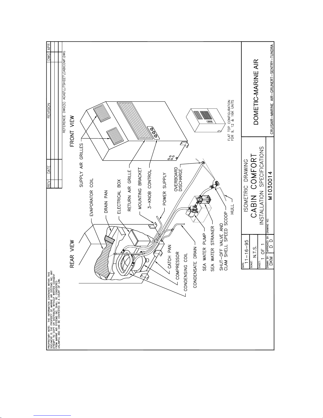
Cabin Comfort Overview Diagram .....…………………………………………. 3
Preface................................................................................................................... 4
Unpacking and Inspection .................................................................................... 5
Safety Considerations ........................................................................................... 5
Placement Recommendations ............................................................................... 5
Seawater Pump and Plumbing .............................................................................. 6
Seawater Pump Installation Diagram …………………………………………… 7
Mounting the Unit ................................................................................................ 8
Condensate Drains ................................................................................................ 9
Electrical ............................................................................................................... 10
Bonding/Grounding .............................................................................................. 11
Wiring Diagrams ……………………………………………………………….. 12-14
Operating Instructions .......................................................................................... 15
Troubleshooting Guidelines ................................................................................. 16-17
Maintenance ......................................................................................................... 18
Limited Warranty ................................................................................................ 19
This manual is intended to provide the information necessary to ensure proper installation,
operation, and maintenance of the Cabin Comfort Series units. Improper installation or
misunderstood operating procedures can result in unsatisfactory performance and/or premature
failure of these units. Before proceeding, read this manual completely. The Cabin Comfort
Series units are covered under the existing Dometic Corporation warranty policy contained in
this manual. In the interest of product improvement, specifications and design are subject to
change without prior notice.
NOTICE CLEAN AIR ACT AMENDMENTS OF 1990 [TITLE VI - SECTION 608(C-1)]
“Effective July 1, 1992, it shall be unlawful for any person, in the course of maintaining,
servicing, repairing, or disposing of an appliance or industrial process refrigeration, to knowingly
vent or otherwise knowingly release or dispose of any Class I* or Class II** substance used as a
refrigerant in such appliance (or industrial process refrigeration) in a manner which permits such
substance to enter the environment. De minimis releases associated with good faith attempts to
recapture and recycle or safely dispose of any such substances shall not be subject to the
prohibition set forth in the proceeding sentence.”
*Class I substances include CFC-12 **Class II substances include HCFC-22
2
3

Preface
Congratulations on the purchase of your Cabin Comfort air conditioner. No matter which of the
following features was the reason you purchased this unit, we are sure it will meet your needs
and will give you many years of efficient and trouble free use.
The Cabin Comfort Series units are self-contained, reverse cycle air conditioners. These units
are designed for marine applications incorporating the following features:
• Cupro-nickel condenser coil
• Raised lance fin designed evaporator coils
• 1-1/2" deep drain pan with multiple condensate drain locations
• Pre-charged and pre-wired systems for easy connections
• Charge guard protection system integrity during handling and installation
The controls included with this unit are designed specifically for the unique requirements of the
Cabin Comfort environmental control systems and their applications. The controller has been
designed with the flexibility and the following “user friendly” features customers require for their
applications.
• Variable fan speed selection
• On - Start - Run switch
• Dependable mechanical thermostat
• Pre-wired control cable
Marine Air Systems is a product of Dometic Corporation. Dometic is a recognized leader in
the design and manufacture of high-performance comfort control systems, refrigeration products
and battery charging products for demanding environments, including commercial and
recreational marine craft, vehicles and other applications. We offer an unparalleled scope of
products, dealer networks, applications support, engineering resources and production
capabilities throughout the world. Our team has many years of experience in the design,
manufacture, application and support of our products. Our practical experience and design
capability allows our application engineers and sales representatives to offer optimum solutions
for your environmental control requirements. Product lines also include well known Cruisair®,
Grunert®, and Sentry™.
Copyright 2004 Dometic Corporation, All Rights Reserved
Every precaution has been taken in the preparation of this manual to ensure its accuracy. However, Dometic
Corporation assumes no responsibility for errors and omissions. Neither is any liability assumed for damages
resulting from the use of this product and information contained herein.
4

Unpacking and Inspection
Move units in the normal “up” orientation as indicated by the arrows on each carton. When the
equipment is received all items should be carefully checked against the bill of lading to be sure
all cartons have been received. Examine units for shipping damage, removing the units from the
cartons if necessary. Units in question should also be internally inspected. If the unit is
damaged, the carrier should make the proper notation on the delivery receipt acknowledging the
damage.
Safety Considerations
Installation and servicing of this system can be hazardous due to system pressure and electrical
components. Only trained and qualified service personnel should install, repair, or service
equipment. Untrained personnel can perform basic functions of maintenance such as cleaning
coils and replacing filters.
Warning: Before performing service or maintenance operations on system, turn off main
power to unit. Electrical shock could cause personal injury or death.
When working on this equipment, always observe precautions described in the literature, tags,
and labels attached to the unit. Follow all safety codes. Wear safety glasses and work gloves and
place a fire extinguisher close to the work area.
Placement Recommendations
Since the Cabin Comfort Series is a self-contained unit, it can readily be used to cool any desired
area. However, the physical location of the air conditioner is an important factor to consider
prior to installing the unit. The unit should be installed in a central location in the room to be
cooled with adequate space around the unit for maintenance as well as a free flow of supply and
return air.
Regardless of which BTU size unit you are installing, make sure that the unit is positioned on a
firm, level, horizontal surface and that the condensate drain tube is able to run downward from
the unit to a suitable drain location. INSURE THAT THE SELECTED LOCATION IS
SEALED FROM DIRECT ACCESS TO BILGE VAPORS.
Selecting a good location for your air conditioner is the most important part of your preparations.
Be sure to consider the size of the area you are cooling, the air distribution needs, and the
physical size of the unit you have chosen. Then, plan all connections which must be made;
condensate drain, cooling water in and out, electrical connections, and pump placement, to assure
easy access for routing and servicing.
5

Seawater Pump and Plumbing
The seawater thru-hull inlet should be a minimum of 3/4" inside diameter (I.D.) for 1 or 2 units
or 1" I.D. for up to 5 units. It should be located as near to the keel as practical and utilizing a
speed scoop to insure positive water flow while the vessel is underway. A full flow bronze sea
cock should be used, so that you have the ability to disrupt the incoming water to the sea strainer
and circulator pump should the need arise.
Since the circulation pump is centrifugal and not self-priming, it must be mounted well below the
water line. It is, therefore, recommended that all hose type connections below the water line be
secured by means of double hose clamping. A sea strainer located between the sea cock and
pump is essential to protect the pump from foreign matter, such as seaweed. With the water
pump installed, a gradual incline should exist from the sea cock to the strainer to the pump.
Note: All pump warranties will be void unless a sea strainer is installed.
From the discharge outlet of the pump, route your plumbing to the lower hose connection at the
condenser coil. This hose should be plumbed with as few bends and restrictions as practical with
no loops or vertical bends so that they are self-draining and consequently self-purging. The
discharge outlet of the condenser must be plumbed overboard using a discharge thru-hull located
above the water line. The location selected for the overboard discharge thru-hull should be
accessible for periodic visual inspection. A 5/8" hose is required when plumbing from the pump
or manifold to the condenser coil and the overboard discharge thru-hull fitting. It is
recommended that reinforced hose be used as well as double hose clamping.
Since the seawater system has components mounted below the water line, a recap of the
installation is in order:
1. Select a location of the speed scoop thru hull inlet as close to the keel as possible.
2. Bed the sea cock with a marine type sealant designed for underwater applications.
3. Install a bronze, full flow sea cock on the thru-hull
4. Use a sea strainer to protect the pump.
5. Mount the pump below the water line insuring that an incline exists between the sea cock and
the pump.
6. Double clamp all hose connections.
7. Maintain a minimum of 5/8" I.D. hose for the pump or manifold to the condenser.
8. Discharge the water through a hull-side thru-hull fitting above the water line, with access for
visual inspection.
9. No loops or vertical bends will insure self-draining and consequently self-purging.
See next page for seawater pump installation diagram.
6
 Loading...