

Page 1
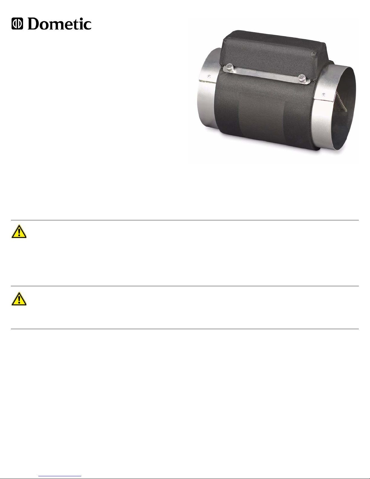
Breathe Easy Air Purifier
In-Duct Model
Installation & Operation Manual
HOW IT WORKS
The In-Duct Dometic Breathe Easy Air Purifier uses your marine air
conditioning system’s blower to move air through the unit where
ultraviolet (UV) light and innovative Photocatalytic Nano-Mesh
technology improve air quality.
The unit uses a specific frequency of UV light that enables maximum
effectiveness in reducing pollutants such as pollen, mold spores,
bacteria, viruses, fumes, and odors, yet it produces no harmful ozone.
UV energy activates the titanium-dioxide catalyst on the surface of the
nano-mesh structure. The molecules of pollutants that come in contact
with the catalyst are reconfigured into nontoxic elements.
The density and quantity of pollutants present affect how rapidly the air will be cleaned. As air re-circulates and makes multiple passes through the
system you will notice continuously improving purification levels.
NOTE: The air purifier does not fix the source of ongoing odor problems. For example, a leak that caused mold must be repaired and the mold
must be removed.
SAFETY PRECAUTIONS
WARNING
• Do not use outdoors.
• Keep the cord away from heated surfaces.
• Never open the cover without turning off the main breaker.
• Never operate this unit if it has a damaged cord or plug.
• Never operate this unit if it has been damaged or submerged in water.
• Do not place in an area where uncured siliconized sealers are being used, as the vapors will inhibit the unit’s photocatalytic
capability.
DANGER
• Never look directly at a lit ultraviolet (UV) bulb. The direct power of the UV bulb can be harmful to the eyes. However,
looking at the indirect blue glow from the bul b is safe.
• This equipment is not ignition protected per CFR 183.410 and may not be installed in areas that may be exposed to
flammable gas.
SYSTEM SETUP
Selecting the Location
• This unit is designed for installation within the supply-air ducting of an air conditioning system positioned downstre am of the blower.
• If there is a T-box or other diverter box attached to the blower, position the unit in line with the side that gets the most air. Or, relocate the
diverter box away from the blower and place the Breathe Easy between the blower and the diverter. If the unit is installed downstream of
a diverter box, be sure the diameter of the Breathe Easy matches the diameter of the outgoing duct. (For example, a diverter box could
have 6” ducting going in, then have 2”, 4”, and 5” branches going out, so you would need a 5”-diameter unit instead of a 6”-diameter unit
to place it on the outgoing branch that gets the most air.)
• Make sure the ducting that connects to the air purifier is UV-stable. If you can not confirm that it is, replace the ducting in the area
stretching at least 3 feet (1m) before and 3 feet (1m) after the unit with UV-stable ducting to prevent eventual deterioration of the ducting.
Deteriorated ducting may create air leaks that could cause secondary condensation.
• The ducting should service an indoor area.
• The unit requires annual replacement of the UV bulb, so situate the unit for easy access to both the bulb housing and the bulb ballast.
• The unit requires electricity and operates on 115V/60Hz, 220V/50Hz, or 230V/60Hz AC power. Its power supply is auto-sensing, so no
rewiring of ballast or switching is needed to match operating voltage and Hz. See “Power” for electrical specifications.
• Do not install in areas that may be exposed to flammable gas.
14
Page 2
Power
DO NOT WIRE UNIT
OR THE BALLAST
TO BLOWER POWER
WILL BE DAMAGED
AND UV BULB LIFE
WILL BE GREATLY
REDUCED.
AC:
115/60Hz,
220V/50Hz,or
230V/60Hz
A
I
R
F
L
O
W
12
3
4
5
6
7
4
8
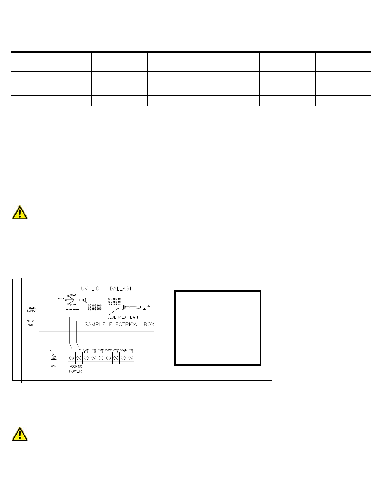
The unit operates on 115V/60Hz, 220V/50Hz, or 230V/60Hz AC power and is wired to the incoming power of the air conditioning system. The
unit’s power supply is auto-sensing, so no rewiring of ballast or switching is needed to match operating voltage and Hz. Do NOT wire the unit to
blower power, as this will significantly reduce the life of the UV bulb and cause damage to the ballast . See table below for electrical
specifications and Figure 1 for wiring information.
ELECTRICAL
SPECIFICATIONS
Volts/Hz/mA
UV Bulb Watt s
Installation
1. Determine the optimum location within the ducting route (see “Selecting the Location”).
2. Cut the ducting to make room for unit. Make sure the ducting in the areas 3 feet (1m) before and 3 feet (1m) after the unit is UV stable. If
not, replace that area with ducting that is UV stable. When cutting the ducting leave enough length to cover the ends of the Breathe Easy
tube without having to stretch the ducting, but no so much length that you create bends or kinks.
3. Determine the direction of air flow and install the tube per the air-flow arrow on the bulb housing. Note that the incoming air enters the
tube at the end opposite the power-cord end. (See Figure 2.)
4. Position the unit so the bulb housing is easily accessible for annual bulb replacement (see Figure 2) and write in the in-service month and
year on the “Replacement Due Date” sticker.
5. Attach the UV-stable ducting to each end of the unit. Use at least 3 large-head screws per side to catch the ducting wire then use a tie
strap around the connection. Finish with duct tape to ensure a good air-tight seal.
WARNING
An air leak at the duct connection could cause secondary condensation to form, resulting in drip s & wetness in the surrounding area.
6. Turn off the breaker to the air conditioning system’s incoming terminal strip.
7. Connect the Breathe Easy to incoming AC power at the air conditioning system’s incoming terminal strip and follow the wiring diagram
shown in Figure 1.
8. Turn breaker on. Look for a blue glow coming from the unit. Never look directly at a lit UV bulb! Or, verify that the blue pilot light on the
ballast is lit, which indicates the bulb is working. The blue pilot light will be lit only if power is applied to the unit and the bulb is operational
(i.e., if the bulb is not properly seated but power is connected, the pilot light will not be lit). See the location of the pilot light in Figure 1.
N-DUCT MODEL 5” IN-DUCT MODEL 6” IN-DUCT MODEL 7” IN-DUCT MODEL 8” IN-DUCT MODEL
4” I
115/60/200
220/50/350
230/60/200
12 12 12 20 20
115/60/200
220/50/350
230/60/200
115/60/200
220/50/350
230/60/200
115/60/250
220/50/350
230/60/225
115/60/250
220/50/350
230/60/225
Figure 1: Electrical Wiring Diagram
SYSTEM OPERATION
On
The Breathe Easy unit is in operational ready mode when power is supplied to the unit and the bulb is lit and the blue pilot light on the ballast is lit.
The air purification process begins when the air conditioning system’s blowers begin moving air through the tube.
Off
Disconnect power to the unit by turning off the breaker to the air conditioning system’s incoming terminal strip. Always turn the unit off when
performing maintenance.
NOTE
It is normal for the Breathe Easy UV bulb to remain lit as long as power is applied to the unit at the breaker, even if the AC unit is in
OFF mode. This maximizes the life of the bulb. One hou r of bu lb life is lost each time it is turned on and off, which is why the unit
should never be wired to blower power.
Page 3

MAINTENANCE
A
I
R
F
L
O
W
12
3
4
5
6
7
4
8
Replacing the UV Bulb
Like all light bulbs, UV bulbs have a limited life span. Unlike regular light bulbs that work until they burn out, UV bulbs lose their germicidal
effectiveness over time and must be replaced even though they may still produce light.
After approximately 1 year of continuous use (about 9,000 hours), the UV bulb will lose power and have to be replaced. Replace with a new
Dometic UV bulb (see “Replacement Parts”). Use of any other bulb will void the warranty.
NOTE
The bulb will still glow blue afte r 9,000 hou rs of use, but the UV radiation wi ll not be strong en ough to be fun ctional . If the bulb
is glowing red or orange instead of a bright pu rple-blue, the bulb needs to be replaced immediately.
Refer to Figure 2 below and follow these steps to replace the bulb:
1. Disconnect power to the unit by turning off the breaker to the air conditioning system’s incoming terminal strip.
2. Allow 5 minutes for the bulb (#1) to cool.
3. Loosen the finger screws (#2) to open and lift out the bulb housing (#3).
4. Pop the power-cord strain relief (#5) out of the housing (#3) to give easier access to the plug. Pull the bulb out of the power plug socket
then twist the bulb to remove it from the bulb clips (#4).
5. Take a new Dometic UV bulb (#1) (see “Replacement Parts”) and twist the bulb to insert it into the bulb clips (#4) then slide it toward the
power-cord strain relief (#5) end of the housing (#3) to create a 3/16-inch (5mm) gap (#8) between it and the housing (#3). Write the
in-service month and year on the “Replacement Due Date” sticker (included with the bulb) and attach it over the old sticker.
6. Insert the bulb prongs firmly into the power plug socket. If the prongs don’t fit, rotate the socket 90 degrees.
7. Slide the power-cord strain relief (#5) back into the housing (#3) making sure to orient it as shown in Figure 2: The plug goes to the
inside, the side of the strain relief with 2 pressure clips goes toward the open area of the housing and the side of the strain-relief with 1
pressure clip goes toward the closed area of the housing. It is important to seat the power-cord strain relief correctly to avoid air leaks
that could cause secondary condensation.
8. Insert the lip of the housing (#3) into the tube (#6), align the finger screws with the screw holes, then tighten the finger screws (#2). Check
for any misalignment that could cause air leaks and correct any you find. It is important to seat the housing correctly to avoid air leaks
that could cause secondary condensation.
9. Reconnect power to the unit by turning on the breaker to the air conditioning system’s incoming terminal strip.
10. Look for a blue glow coming from the unit. Never look directly at a lit UV bulb! Or, verify that the blue pilot light on the ballast is lit, which
indicates the bulb is working. (See the location of the pilot light in Figure 1.)
Figure 2: Diagram of the Breathe Easy In-Duct Tube
1 UV Bulb
2 Finger Screws
3 Bulb Housing
4 Bulb Clips (2 pairs)
5 Power-Cord Strain Relief
6 Breathe Easy Tube
7 Nano-Mesh Structure
NOTE: A slight twist in the
structure is normal and should
not be straightened. This shape
creates a vortex for better
purification of the air.
8 Gap Between Bulb and Housing
NOTE: You must have a 3/16”
(5mm) gap between bulb and
housing.
32
Page 4

CLEANING
Nano-Mesh Structure
Normally the nano-mesh structure of the Breathe Easy Air Purifier is self cleaning and needs no maintenance. In rare instances, however, if debris
accumulates and air purification decreases you may need to clean it. Make sure power is disconnected before opening the tube . (See
“Replacing the UV Bulb” for opening and closing instructions.) Blow away debris with canned air suitable for use on computers.
UV Bulb
Air purification effectiveness will decrease if the UV bulb is dirty, and under extreme conditions you may need to clean it. Make sure power is
disconnected before opening the tu be. (See “Replacing the UV Bulb” for opening and closing instructions.) Gently clean the bulb using rubbing
alcohol on a soft cloth.
TROUBLESHOOTING
No power, unit does not turn on (no blue glow).
1. Make sure the unit is wired to the breaker of the air conditioning system’s incoming terminal strip and the breaker is on.
2. Verify that the power source is working.
3. UV bulb is not seated correctly in the socket (see “Replacing the UV Bulb”).
4. UV bulb needs to be replaced (see “Replacing the UV Bulb”).
5. Blue light on the ballast is not lit (see “Replacing the UV Bulb”).
6. Replace ballast if you have a known good bulb and power is on to ballast (confirmed with a volt meter at power terminals).
Output seems ineffective.
1. Make sure unit is servicing an enclosed area.
2. Remove any obstructions in the air stream’s input and output vents.
3. Clean the air filter of the air conditioning system.
4. Is it time for a new bulb? The UV bulb should be replaced each year (see “Replacing the UV Bulb”).
5. Replace bulb if it is gowing red, not blue (see “Replacing the UV Bulb”).
6. Clean the Nano-Mesh structure (see “Cleaning”).
7. Clean the UV bulb (see “Cleaning”).
REPLACEMENT PARTS
Replacement parts can be ordered from any Dometic dealer. To find a dealer near you, go to: www.dometicusa.com
REATHE EASY AIR PURIFIER
B
UBE DIAMETER
T
4”, 5”, or 6” diameter 4210800 UV Bulb, 5-inch
7” or 8” diameter 4210802 UV Bulb, 8-inch
UV BULB REPLACEMENT
PART NUMBER
REPLACEMENT PART
DESCRIPTION
WARRANTY
The In-Duct Dometic Breathe Easy Air Purifier is covered by a limited warranty against defective material for 1 year from date of purchase. This
warranty covers electronic parts only and does not include the UV bulb. The original product sales receipt is required as proof of purchase.
This warranty does not apply if a unit has been dropped, damaged, or submerged in water.
T o file a warranty claim, contact a Dometic dealer. To find a dealer near you, go to: www.dometicusa.com
COPYRIGHT © 2009-2010 Dometic Marine Division. All Rights Reserved.
No part of this publication may be reproduced, translated, stored in a retrieval system, or transmitted in any form or by any means electronic, mechanical, photocopying, recording or otherwise without prior written consent by Dometic Marine. Every precaution has been taken in the preparation of this manual to ensure its
accuracy. However, Dometic Marine assumes no responsibility for errors and omission. Neither is any liability assumed for damages resulting from the use of this
product and information contained herein.
L-2753 Rev 20100426
 Loading...