

Page 1
BLUTEC 40d
Operation, maintenance and installation manual
Libretto istruzioni per l’uso, la manutenzione e l’installazione
Betriebs-, Wartungs- und Installationsanleitung
Manuel d’utilisation, d’entretien et d’installation
Bedienings-, onderhouds- en installatiehandleiding
Manual de instrucciones para el uso, mantenimiento e instalación
Manual de instruções de uso, manutenção e instalação
Användning, underhåll och installation
Käyttö-, huolto- ja asennusohje
Bruks-, vedlikeholds- og installasjonsanvisning
Betjenings-, vedligeholdelses- og installationsvejledning
Kullanım, bakım ve kurulum talimatları kitapçığı
Οδηγίες χρήσης, συντήρησης και εγκατάστασης
Page 2

ENGLISH
With Dometic you are at home, everywhere. Thank you for having
chosen one of our products. This Dometic product has been
specifically designed for your vessel. With over 75 years experience,
Dometic satisfies your mobile leisure needs thanks to state-of-the-art
technology and top quality materials, combined with great care for the
environment.
ITALIANO
Con Dometic come a casa, ovunque. Vi ringraziamo per averci scelto.
Questo prodotto Dometic è stato espressamente concepito per la
Vostra imbarcazione. Dometic, con un'esperienza di oltre 75 anni,
soddisfa completamente le esigenze del tempo libero in movimento,
utilizza le tecnologie più avanzate e materiali di prima qualità con
estrema attenzione per l'ambiente.
DEUTSCH
Mit Dometic wie zuhause - überall. Wir bedanken und freuen uns, dass
Sie sich für ein Produkt unserer Marke entschieden haben. Dieses
Dometic-Produkt wurde von uns speziell für Ihre Yacht entworfen. Alle
Dometic-Produkte basieren auf mehr als 75 Jahren Erfahrung in der
Ausstattung von Freizeityachten, modernster Technologie,
erstklassigen Materialien und zeichnen sich durch ihre
Umweltfreundlichkeit aus.
FRANÇAIS
Avec Dometic, partout comme à la maison. Nous vous remercions de
votre préférence. Ce produit Dometic a été conçu spécifiquement pour
votre embarcation. Grâce à son expérience de plus de 75 ans, Dometic
répondra pleinement à vos exigences liées au temps libre en
mouvement, car elle adopte les technologies les plus avancées et des
matériaux de première qualité, avec une attention particulière pour
l'environnement.
NEDERLANDS
Met Dometic voelt u zich thuis, overal. We danken u ervoor dat u ons
heeft gekozen. De producten van Dometic zijn speciaal ontworpen
voor uw vaartuig en spelen volledig in op de behoeften van uw vrije tijd.
Door onze ervaring van meer dan 75 jaar kunnen wij u de meest
geavanceerde technologie, eersteklas materialen, een fantastische
technische ondersteuning en functionele design aanbieden. Ook met
het milieu is zorgvuldig rekening gehouden.
ESPAÑOL
Con Dometic como en casa, allí donde esté. Gracias por elegir un
producto Dometic diseñado específicamente para su embarcación.
Gracias a una experiencia de más de 75 años, Dometic es capaz de
satisfacer todas las exigencias del tiempo libre en movimiento y utiliza
tecnología avanzada y materiales de primera calidad respetuosos con
el medio ambiente.
PORTUGUÊS
Com Dometic como em casa, em qualquer lugar. Agradecemos a sua
preferência. Este produto Dometic foi expressamente concebido para
a sua embarcação. A Dometic, com uma experiência de mais de 75
anos, satisfaz completamente as exigências do tempo livre em
movimento, utiliza as tecnologias mais avançadas e materiais de
primeira qualidade com extrema atenção ao meio ambiente.
SVENSKA
Med Dometic känner du dig som hemma var du än befinner dig. Tack
för att du har valt en av våra produkter. Företaget har mer än 75 års
erfarenhet i branschen och produktframtagningen grundar sig på
mycket avancerade teknologier, förstaklassiga material och extrem
omsorg om miljön, vilket gör att Dometic kan tillgodose alla dina behov
av bekvämlighetsprodukter för fritidsbåtar.
SUOMI
Dometic-generaattorin ansiosta olet kuin kotonasi, missä tahansa
oletkin. Onnittelut valinnastasi. Tämä Dometicin tuote on suunniteltu
erityisesti vesialuksia varten. Dometicin 75 vuoden kokemukseen
perustuen pystymme täyttämään täydellisesti vapaa-ajan liikkumiseen
liittyvät vaatimukset hyödyntäen huipputeknologiaa ja korkealaatuisia
materiaaleja ja kiinnittäen erityistä huomiota ympäristönäkökohtiin.
NORSK
Dometic overalt, akkurat som hjemme. Takk for at du valgte oss. Dette
produktet har blitt uttrykkelig designet med tanke på fartøyet ditt.
Dometic, med mer enn 75 års erfaring, tilfredsstiller alt du trenger til en
fritid i bevegelse og de benytter det siste innen teknologien og
førsteklasses materialer med ekstra hensyn til miljøet.
DANSK
Med Dometic som derhjemme, overalt. Vi takker, fordi I har valgt os.
Dette Dometic produkt er netop udformet til jeres båd; Med mere end
75 års erfaring opfylder Dometic fuldt ud behovet i fritiden i bevægelse
og bruger de mest avancerede teknologier og første klasses materialer
med stor miljøbevidsthed.
TÜRKÇE
Dometic ile her yerde evinizde gibi. Bizi seçtiğiniz için teşekkür
ederiz. Bu Dometic ürünü, tekneniz için etkileyici bir tasarıma
sahiptir. Dometic, 75 yılı aşkın bir tecrübe ile seyahat esnasında
duyulan boş zaman değerlendirme gereksinimlerini karşılar,
çevreye karşı son derece dikkatli bir şekilde, en ileri teknolojiyi ve
nıf kalitede malzemeler kullanır.
birinci sı
ΕΛΛΗNIKA
Με την Dometic σαν στο σπίτι σας, παντού. Σας ευχαριστούµε για
την προτίµησή σας. Το παρόν προϊόν της Dometic έχει µελετηθεί
ειδικά για το σκάφος σας. Με την εµπειρία των 75 και πλέον ετών
που διαθέτει η Dometic, µπορεί να ικανοποιεί πλήρως τις
απαιτήσεις για τον ελεύθερο χρόνο εν κινήσει και χρησιµοποιεί τις
πιο προηγµένες τεχνολογίες και υλικά πρώτης ποιότητας µε
απόλυτο σεβασµό προς το περιβάλλον.
Page 3

Operation, Maintenance and
Installation manual
Marine generator
Libretto istruzioni per l’uso, la
manutenzione e l’installazione
Generatore marino
Bedienungs- und
Wartungsanleitung
Bordgenerator
Mise en route, entretien
et installation
Générateur marin
Bedienings-, onderhouds- en
installatiehandleiding
Nautische generator
Manual de instrucciones para el
uso, mantenimiento e instalación
Generador marino
Manual de instruções de uso,
manutenção e instalação
Gerador marítimo
Användning, underhåll och
installation
Maringenerator
Käyttö-, huolto- ja
asennusohje
Laivageneraattori
Bruks-, vedlikeholds- og
installasjonsanvisning
Båtgenerator
Betjenings-, vedligeholdelses- og
installationsvejledning
Marinegenerator
Kullanım, bakım ve kurulum talimatları
kitapçığı
Deniz jeneratörü
C140200701.fm
Οδηγίες χρήσης, συντήρησης και
εγκατάστασης
Γεννήτρια θαλάσσης
English
Italiano
Deutsch
Français
Nederlands
Español
Português
Svenska
Suomi
Norsk
Dansk
Türkçe
ΕΛΛΗNIKA
GB
I
D
F
NL
E
P
S
FIN
N
DK
TR
GR
Page 4

© DOMETIC - 2006 All rights reserved - Printed in Italy Made by IDM
No part of this manual may be duplicated, copied or published in
any form without written authorization from DOMETIC
The figures, descriptions, references and technical data contained
in this manual are merely guidelines and are not binding
DOMETIC reserves the right to make all the modifications it may
deem fit, at any time and without notice, in a constant effort to
improve quality and safety, without undertaking to update this
manual every time.
© 2006 - Texts by: IDM experts in technical communication - Forlì
- The text may be reproduced , either partially or in full, provided the
author is duly cited.
Keep this document for future reference.
Page 5

CONTENTS
GENERAL INFORMATION................................. 6
TECHNICAL INFORMATION.............................. 8
SAFETY INFORMATION .................................. 11
INFORMATION ON MOVEMENT AND
INSTALLATION ................................................15
INFORMATION ON ADJUSTMENTS ............... 23
TABLE OF CONTENTS
A
Adjustment method
C
Changing engine oil
Changing the fuel filter (28)
Changing the sacrificial anode (28)
Changing the water pump rotor (31)
Check oil level (26)
Connecting the battery (21)
Connecting the battery charger (21)
Connecting the fuel indicator (21)
Connection to the exhaust (22)
Connection to the external power supply (34)
Connection to the power supply (20)
Cooling water connection (22)
D
Decommissioning the unit
Description of controls (23)
E
Electrical connection to the external network
F
Finding malfunctions
Fuel connection (22)
G
General description of the appliance
General rules (11)
Glossary and terms (7)
I
Improper use
Installing the unit (16)
L
Loading and transport
(23)
(27)
(32)
(21)
(29)
(8)
(10)
(15)
INFORMATION ON USE .................................. 23
MAINTENANCE INFORMATION ..................... 25
TROUBLESHOOTING INFORMATION ........... 29
INFORMATION ON SPARE PARTS................ 31
WIRING DIAGRAM........................................... 33
M
Main components
Manufacturer and appliance identification (6)
Movement and lifting (16)
P
Packing and unpacking
Prolonged inactivity of the unit (24)
R
Recommendations for maintenance
Recommendations for movement and installation (15)
Recommendations for use and operation (23)
Recommendations when changing parts (31)
Recommended lubricants (26)
Requesting assistance (7)
Rules for adjustment and maintenance (12)
Rules for movement and installation (11)
Rules for operation and use (12)
Rules for safety from environmental impact (13)
S
Safety and information signs
Safety devices (10)
Safety for the disposal of Waste from Electrical and
Electronic Equipment (WEEE Directive 2002/96)
Scope of the manual (6)
Starting and stopping the unit (24)
Storage (16)
T
Table of alarm signals
Table of maintenance operations (25)
Technical data (9)
Testing the unit (22)
W
Wiring diagram
(8)
(15)
(25)
(14)
(13)
(30)
(33)
GB
C140200701.fm
- 5 -
User manual
Page 6
GENERAL INFORMATION
SCOPE OF THE MANUAL
This manual, which is an integral part of the
equipment, has been drawn up by the manufacturer to provide the information required
GB
by those trained and authorised to work on
and with it during its working life.
This information is supplied by the Manufacturer in the original language (Italian) and
may be translated into other languages to
satisfy legal and/or commercial requirements.
Those to whom this information is addressed
must not only use the appliance in a proper
manner, but must read the information carefully and apply all instructions strictly.
Spending a short time reading this information will allow you to avoid risks that might result in a health or safety hazard and in
economic damage.
Should this manual contain information that
is additional to the actual set-up of the appliance, this additional information will have no
influence on the rest.
Keep this manual in a safe, known and easily
accessible place for the entire working life of
the appliance, so that it is always to hand
when required.
The manufacturer reserves the right to make
all modifications it may deem fit, without undertaking to give any prior notice.
To highlight certain sections of text that are
particularly important or to indicate certain
important specifications, various symbols
have been used. These are described below.
Danger - Attention
Indicates states of severe danger that, if ignored, may seriously endanger the health
and safety of persons.
Warning - Caution
Indicates that it is necessary to take suitable precautions in order to avoid endangering the health and safety of persons
and causing economic damage.
Important
Indicates technical information of particular importance that must not be ignored.
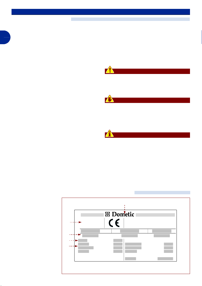
MANUFACTURER AND APPLIANCE IDENTIFICATION
The identification plate
shown here is affixed directly to the appliance.
A) Manufacturer identifi-
cation
B) Conformity markings
C) Model/Serial number
D) Year of manufacture
E) Technical data
B
C
D
E
A
- 6 -
C140200701.fm
IDM - 40200700100.tif
User manual
Page 7

GLOSSARY AND TERMS
Certain terms that are used frequently in the
manual are described, so as to give the fullest possible view of their meaning.
Installation technician: a technician selected and authorised by the Manufacturer or his
agent, from among those with the necessary
qualifications to carry out installation and
testing of the appliance.
Ordinary maintenance: series of operations
necessary to keep the appliance in a state of
proper efficiency and operation. These operations are normally planned by the Manufacturer, who sets down the qualifications
required to carry them out and the intervention method.
REQUESTING ASSISTANCE
For any assistance, please contact the Manufacturer's Service Department.
When requesting technical assistance,
please indicate the information provided on
the identification plate, the approximate
number of working hours and the type of
problem encountered.
Special maintenance: series of operations
necessary to keep the appliance in a state of
proper efficiency and operation. These operations are not planned by the Manufacturer
and must be carried out by the maintenance
technician.
Senior maintenance technician: a technician selected and authorised by the Manufacturer from among those with the
necessary qualifications, experience and information to carry out special maintenance
and repairs on the appliance.
GB
C140200701.fm
- 7 -
User manual
Page 8
TECHNICAL INFORMATION
GENERAL DESCRIPTION OF THE APPLIANCE
The generator unit for vessels "BLUTEC 40
D", is an appliance designed and built to be
installed on board vessels of all types.
GB
It is used in the professional and civil shipping sector to generate current on sea-going
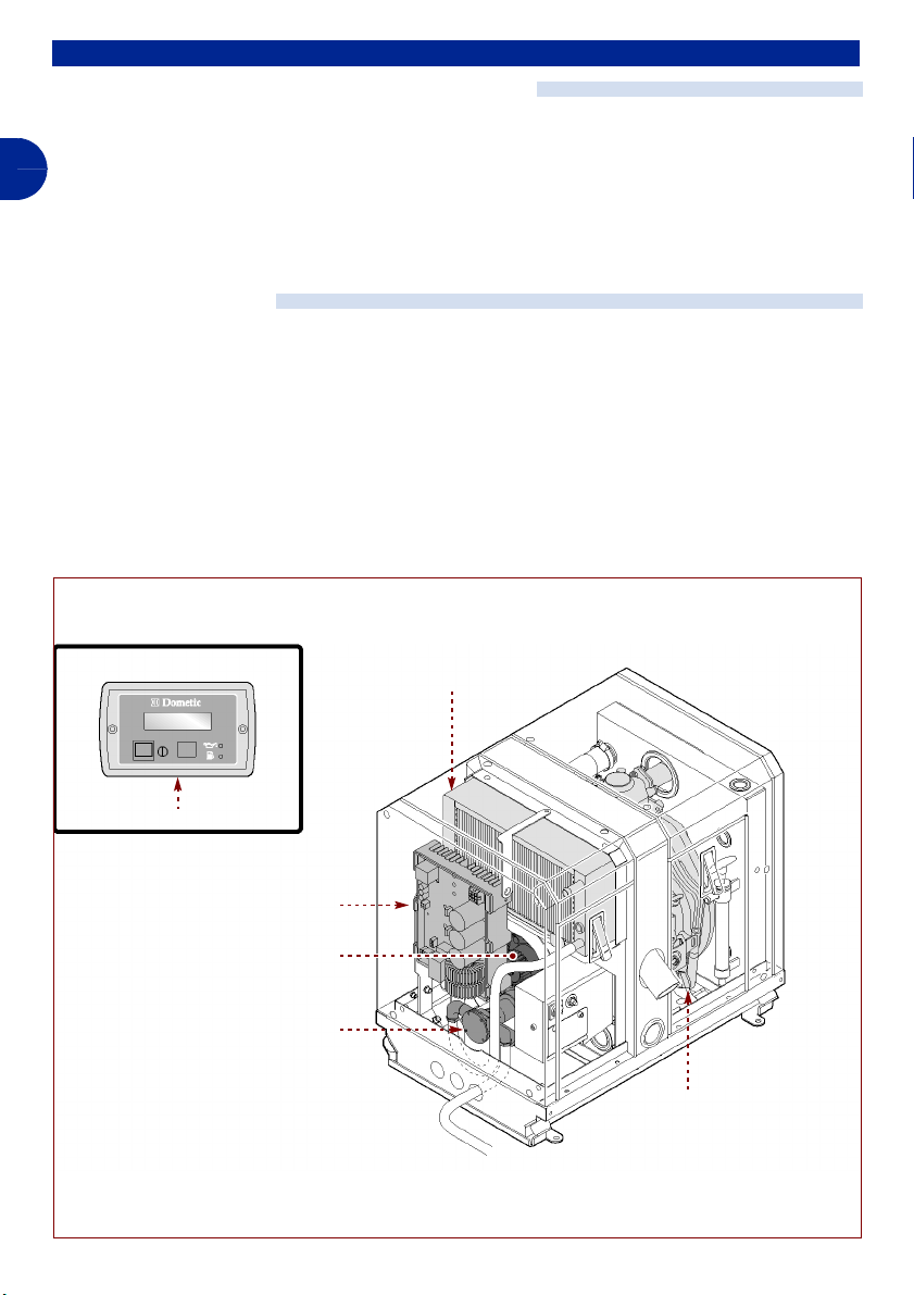
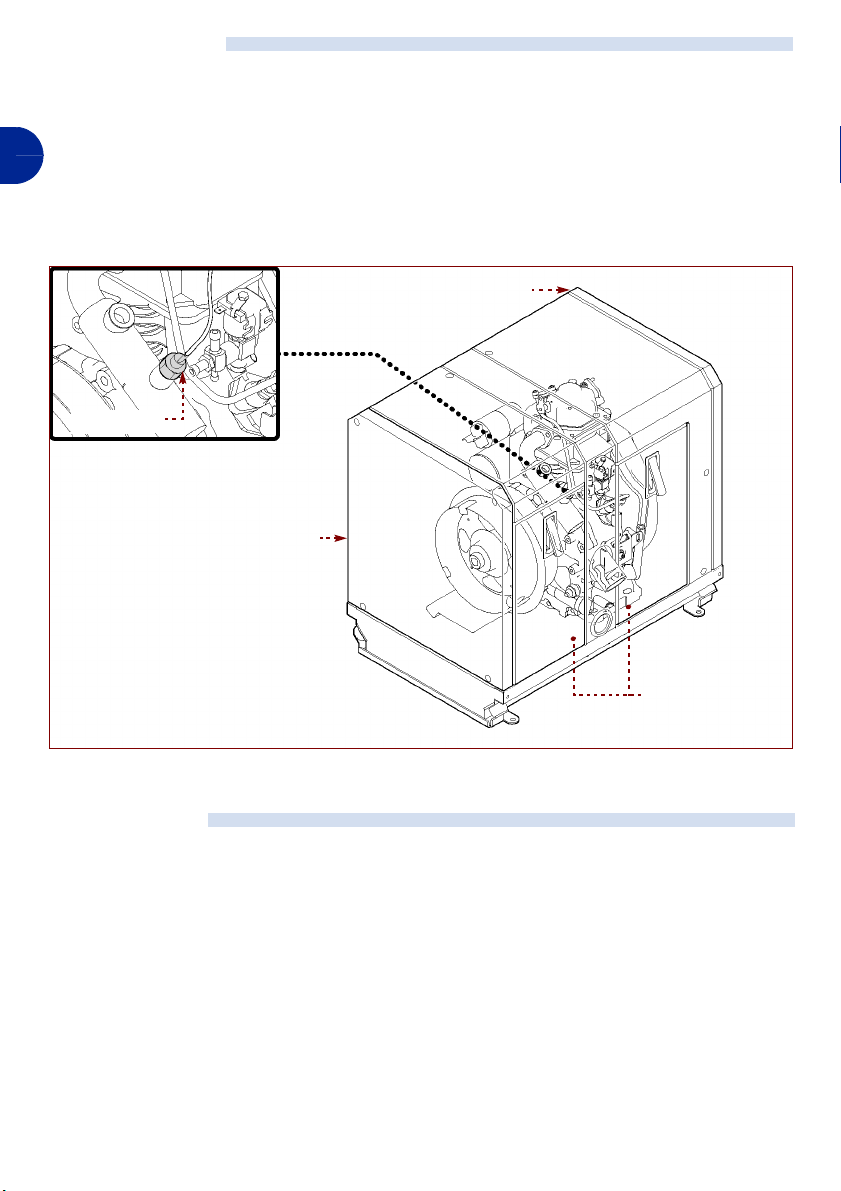
MAIN COMPONENTS
– Endothermic motor (A): to power all the
main components.
– Alternator (B): transofms the mechanical
energy of the motor into alternat current
electrical energy.
– Heat exchanger (C): cools the air inside
the unit through heat exchange with the
sea water.
heat exchanger (C)
vessels.
The appliance is fitted with a control panel,
from which it is possible to controll all working
functions.
– Water pump (D): feeds the sea water
cooling circuit
– Inverter (E): converts the supply voltage
into a perfectly stable, high quality voltage
of 230V/50Hz.
– Control panel (F): comprises the devices
used to operate and control all functions.
control panel (F)
inverter (E)
alternator (B)
water pump (D)
- 8 -
C140200701.fm
endothermic motor (A)
IDM - 40200700200.tif
User manual
Page 9
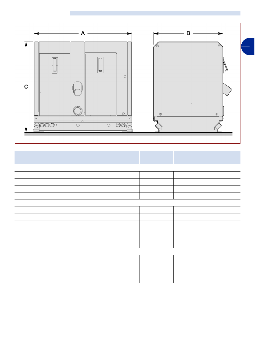
TECHNICAL DATA
GB
IDM - 40200700300.tif
Appliance model
Dimensions
A mm 570
B mm 406
C mm 528
Weight kg 85
Motor technical data
Model YANMAR L 70 N / 320cc
Maximum power HP 6,1
maximum running speed giri/min 3300
Fuel consumption lt 1,3
Oil sump capacity lt 1,1
Inclinazioni consentite ± 20°
Generator technical data
Maximum output (continuous) W 3500
Output voltage V 230±10%
Frequency Hz 50
Insulation Class H
C140200701.fm
Unit of
measurement
BLUTEC 40D
- 9 -
User manual
Page 10
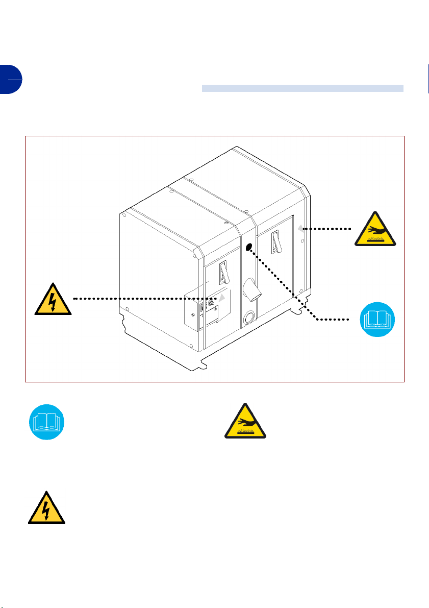
SAFETY DEVICES
The illustration shows the position of the devices.
– Fixed guard (A): prevents access to mov-
GB
ing parts of the unit. It can only be opened
by a voluntary action and with the aid of a
tool.
– Mobile guard (B): prevents access to the
interior of the unit.
sensor (C)
fixed guard (A)
– Temperature probe (C): disables the unit
if the exhaust gas reaches an excessively
high temperature.
fixed guard (A)
IMPROPER USE
Any form of use other than that authorised is
to be considered IMPROPER USE.
mobile guard (B)
Under no circumstances must this unit be
used in explosive environments or when
exposed to the elements.
- 10 -
IDM - 40200700400.tif
C140200701.fm
User manual
Page 11

SAFETY INFORMATION
GENERAL RULES
– When designing and building this unit, the
manufacturer has paid particular attention
to all aspects that might result in a risk to
the health and safety of those working with
the unit itself. As well as complying with
current legal requirements, all "rules of
good manufacturing practice" have been
followed. The aim of this information is to
notify users of the need to pay particular attention, in order to prevent any type of risk.
The need for prudence can never be sufficiently stressed. Safety also depends on
the operators working with the unit.
– Please read the instructions provided in
this manual carefully, and also read the instructions affixed directly to the unit, in particular those relating to safety. Dedicating a
short time to reading this information will
help avoid unnecessary accidents; it is always too late to remember what you should
have done when you have already done it.
– Pay particular attention to the meaning of
the symbols on the unit; their shape and
colour are significant for the purposes of
safety. Make sure they remain legible, and
follow the instructions given.
– Do not tamper with, elude, eliminate or by-
pass the safety devices fitted. Failure to
comply with this requirement may result in
severe risks for the health and safety of
persons.
– Staff carrying out any type of operation on
the unit throughout its working life must
have specific technical qualifications, abilities and experience that has been acquired
in and is recognised by the specific sector.
If these requirements are lacking, damage
to the health and safety of persons may result.
– When working, only use the clothing and/or
personal protection devices indicated in the
instructions for use supplied by the manufacturer, or those foreseen by local laws on
safety in the workplace.
– During normal use or for whatever opera-
tion, always ensure there is sufficient access space to use the comands in
conditions that are not liable to result in a
risk for the health and safety of persons.
– Every operation, unless expressly indicat-
ed, must be carried out with the motor
turned off and after allowing sufficient time
for it to cool down, so as to avoid the risk of
scalding.
GB
RULES FOR MOVEMENT AND INSTALLATION
– Lift and move the unit as described by the
manufacturer and indicated on the packaging, on the unit itself and in the user manual.
– The staff loading, unloading and moving
the unit, must have experience and abilities
gaiend and recognised in the sector in
C140200701.fm
question, and must be familiar with the lifting equipment to be used.
– Loading and transport must be carried out
using means of adequate capacity, anchoring the unit at the points foreseen by the
manufacturer. Those authorised to carry out
– All phases of installation must be consid-
- 11 -
these operations must have specific experience and abilities, so as to safeguard themselves and any other persons involved.
ered, from the time the general plan was
drawn up. Before starting these phases, as
well as defining the installation area, the
person authorised to carry out these operations must, if necessary, implement a "safety plan" to safeguard the persons directly
involved from harm, and must scrupulously
follow all laws, with particular reference to
those regarding mobile work sites.
User manual
Page 12

– It is necessary to ensure that the installa-
tion area has been provided with all the
suction, power supply and drainage connections required.
– During installation, respect the perimeter
GB
areas indicated by the manufacturer, also
bearing in mind all the other operations in
the surrounding areas. This requirement
must be implemented in such a way as to
comply with current laws on safety at work.
RULES FOR OPERATION AND USE
– As well as being suitably trained and in-
formed regarding use of the unit, the operator
must have the abilities and knowledge required for the type of work to be carried out.
– Even after adequate documentation, simu-
late a few test operations on first use, if necessary, so as to identify the various controla
and their main functions, in particular those
relating to start-up and stoppage.
– Only use the unit for the purposes foreseen
by the manufacturer. Improper use of the unit
may result in risks for the health and safety of
persons, and in damage to property.
– Installation and connection must be carried
out according to the manufacturer's instructions. The person in charge must also take
into account all legal requirements and
rules, and must carry out all installation and
connection operations in a workmanlike
manner. When installation has been completed, before use, he must carry out a general check to ensure these requirements
have been met.
– The appliance has been designed and built to
satisfy all the working conditions indicated by
the manufacturer. Tampering with any of the
devices in order to achieve performance levels other than the ones foreseen may result in
risks for the health and safety of persons, and
in damage to property.
– Do not use the unit if the safety devices are
not properly installed and operating correctly.
Failure to comply with this requirement may
result in severe risks for the health and safety
of persons.
RULES FOR ADJUSTMENT AND MAINTENANCE
– Keep the appliance in a state of maximum ef-
ficiency, by carrying out the planned maintenance operations foreseen by the
manufacturer. If these are properly carried
out, they will ensure the appliance provides
optimum performance, a longer working life
and constant compliance with the safety requirements.
– Before carrying out any maintenance or ad-
justments, activate all the safety devices provided and evaluate the need to inform the
persons working on the machine and any
persons in the vicinity. In particular, make
sure that the surrounding areas are adequately marked and prevent access to any of
the devices that might, if active, result in unexpected dangers and risks to the health and
safety of persons.
– Maintenance and adjustment operations
must only be carried out by persons authorised to do so, who must ensure that all the
necessary safety precautions are taken and
that the procedures indicated here are complied with.
– All maintenance operations that require spe-
cific technical knowledge or special abilities
must only be carried out by qualified technicians, who have esperience in the specific
sector of operation.
– To carry out maintenance operations in areas
that are not easily accessible or dangerouse,
ensure that suitable safety precautions are
taken for yourselves and others, in full compliance with current laws on safety at work.
- 12 -
C140200701.fm
User manual
Page 13

– Replace worn components with original
spare parts. Use the oils and greases indicated in the manual. All this will ensure that the
machine retains the functions and safety levels foreseen.
– Do not discard pollutants into the environ-
ment. They must be disposed of according to
current laws.
RULES FOR SAFETY FROM ENVIRONMENTAL IMPACT
Each organisation has the job of applying
certain procedures to identify, evaluate and
control the influence that its own activities
(products, services, etc.) have on the environment.
The procedures to be followed to identify significant impacts on the environment must
take the following factors into account:
– Emissions into the atmosphere
– Discharge of liquids
– Waste management
– Contamination of the ground
– Use of raw materials and natural resources
– Local problems relating to environmental
impact
In order to minimise environmental impact,
the manufacturer provides, below, a series of
indications that should be taken into account
by all those who, for whatever reason, work
with the appliance during its expected working life.
– All packaging components must be dis-
posed of according to current laws in force
in the country in which said disposal takes
place.
– During installation, ensure that the location
is suitably ventilated, so as to avoid any
concentration of air that might be unhealthy
for operators.
– During use and maintenance, do not dis-
perse pollutants into the environment (oils,
greases, etc.) and make sure they are disposed of separately according to the composition of the various materials and in
compliance with current laws in that regard.
Electrical and electronic components
should be disposed of as special waste.
– Keep noise levels down to reduce noise
pollution.
– When decommissioning, select all the com-
ponents according to their chemical characteristics and dispose of them according
to type.
GB
SAFETY FOR THE DISPOSAL OF WASTE FROM ELECTRICAL AND
ELECTRONIC EQUIPMENT (WEEE DIRECTIVE 2002/96)
– Waste from Electrical and Electronic Equip-
ment may contain dangerous substances
that are potentially harmful for the environment and for public health. They must always be disposed of properly.
– When decommissioning, select all the com-
C140200701.fm
ponents according to their chemical characteristics and dispose of them according
to type, in compliance with current laws.
– With reference to the WEEE directive
(Waste from Electrical and Electronic
Equipment), the user, when decommissioning, must separate the electrical and
electronic components and dispose of
them in special authorised collection centres, or return them, still installed, to the
dealer on making a new purchase.
– All the components that must be removed
and disposed of separately are marked by
a special indication.
– Unlawful disposal of Waste from Electronic
and Electrical Equipment (WEEE) is punishable under the laws in force in the country in which any infringement is found.
- 13 -
User manual
Page 14
– For example, to implement European direc-
tives (2002/95/CE, 2002/96/CE, 2003/108/
CE) within Italy, a Decree Law (No. 151 of
GB
SAFETY AND INFORMATION SIGNS
The illustration indicates the position of the
signs affixed to the appliance.
25 July 2005) has been issued, foreseeing
a fine of 2000÷5000 €.
Read the user manual: the operator must read and fully understand the whole contents of
the document to understand the
commands and functions of the
machine. Keep the document
within easy access.
Danger of electrocution: never
access areas that contain live
elements.
- 14 -
IDM - 40200702400.tif
Danger of scalding: beware of
hot surfaces.
C140200701.fm
User manual
Page 15
INFORMATION ON MOVEMENT AND INSTALLATION
RECOMMENDATIONS FOR MOVEMENT AND INSTALLATION
When moving and installing the appliance,
follow the indications provided by the manufacturer and marked on the packaging and in
the instructions for use. Those authorised to
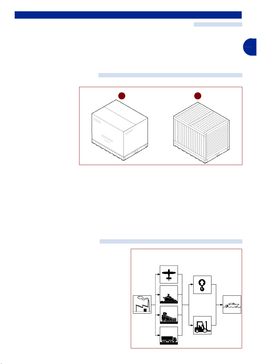
PACKING AND UNPACKING
The packaging, to reduce
working dimensions, may
vary according to the type
of transport being used.
To facilitate transport, the
appliance may be
shipped with some of its
components dismantled
and suitably protected
and wrapped.
Certain parts, particularly
electrical components,
are protected with damp-proof nylon.
All the information required to carry out loading and unloading is indicated on the packaging.
During unloading, check that the components are undamaged and that all the components are present.
carry out these operations must, if necessary, organise a "safety plan" to safeguard
the persons directly involved.
A B
The packing materials must be disposed of in
compliance with current laws.
The packaging may be:
A) on a pallet in a cardboard box
B) in a crate (for overland or air cargo ship-
ping)
GB
IDM - 40200700400.tif
LOADING AND TRANSPORT
Loading and transport, according to the place
of destination, may take place using different
means.
The following diagram illustrates the most
common solutions.
During transport, in order to avoid sudden
movements, make sure the load is adequate-
C140200701.fm
ly fastened to the vehicle.
- 15 -
means of
transport
lifting
equipment
IDM - 40200700400.tif
User manual
Page 16
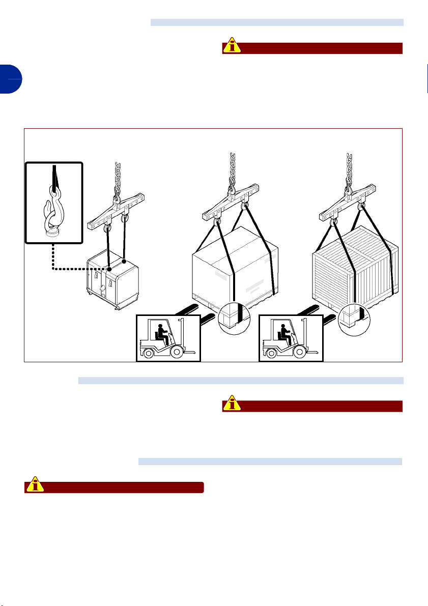
MOVEMENT AND LIFTING
The unit can be moved using a fork lift truck
or hoist of suitable capacity.
To lift and move the unit with an overhead
hoist, use the U-bolts provided.
GB
Important
Before lifting, check that the load is properly centred. Move the load with care, so
as to avoid sudden and dangerous swinging.
WITHOUT PACKING
MATERIALS
CARDBOARD BOX
STORAGE
In the event of prolonged inactivity, check the
conditions of the storage area, the type of
packaging and check that the conditions are
such as to ensure proper maintenance of the
unit.
PACKING WITH
Important
PACKING IN A CRATE
Avoid storing in environments that are
damp or exposed to the weather.
IDM - 40200700700.tif
INSTALLING THE UNIT
Important
All phases of installation must be considered, from the time the general plan was
drawn up. Before starting these phases,
as well as defining the installation area,
the installation technicial who will be carrying out these operations must, if neces-
sary, implement a "safety plan" to
safeguard the persons directly involved
from harm, and must scrupulously follow
all laws, with particular reference to those
regarding mobile work sites.
- 16 -
C140200701.fm
User manual
Page 17
The installation area must have suitable environmental conditions (light, ventilation, etc.).
The floor, as well as having a load capacity
capable of bearing the weight and vibration of
the unit, must be stable and level to guarantee proper support.
The installation area must have all the supply
and drainage connections required.
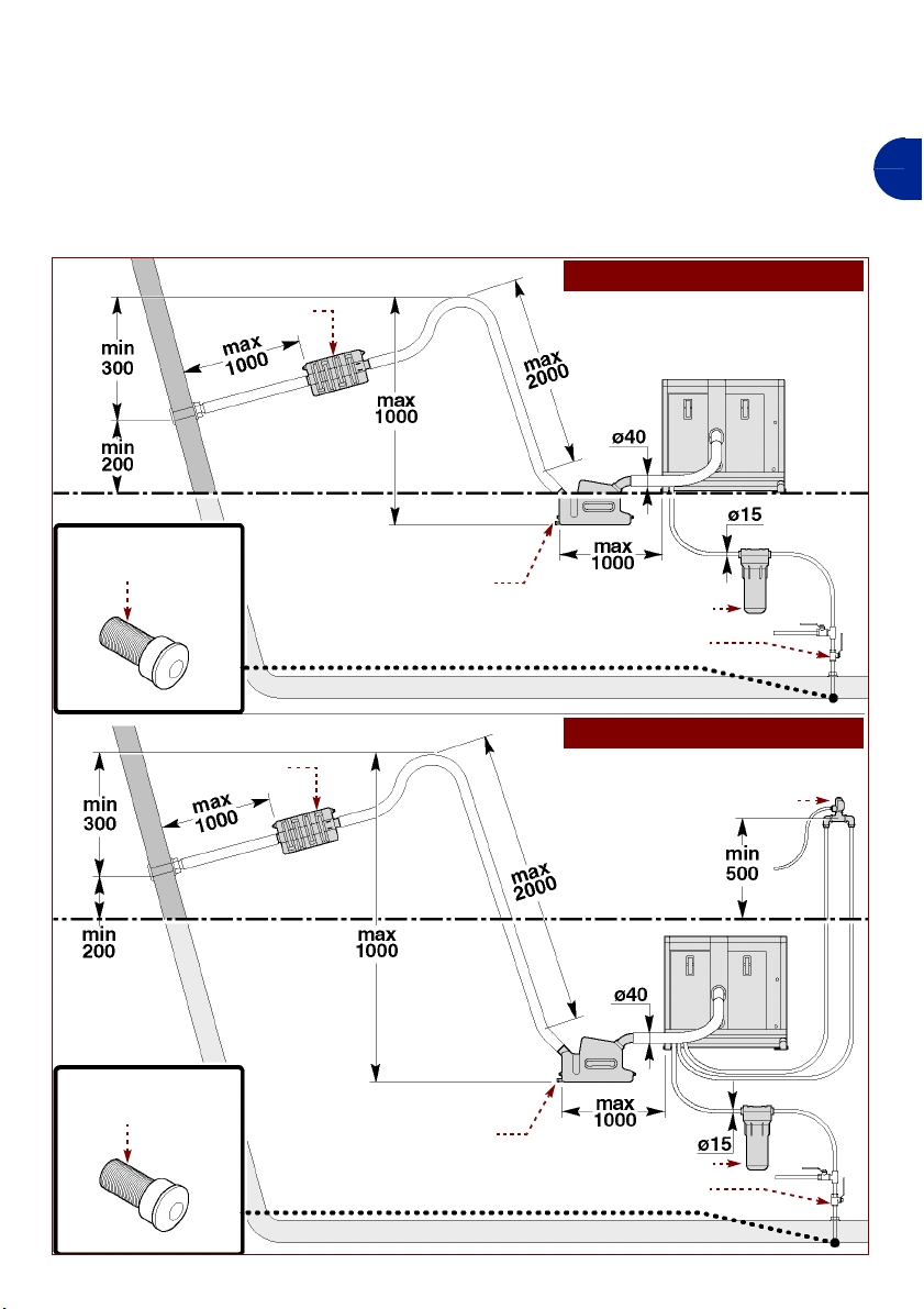
The applicance can be installed in a number
of ways (see figure)
– installation above the water line
– installation below the water line
GB
sea water intake
silencer
water line
silencer
exhaust pipe
INSTALLATION ABOVE THE WATER
sea water filter
non-return valve
INSTALLATION BELOW THE WATER
anti-siphon valve
LINE
LINE
C140200701.fm
sea water intake
water line
exhaust pipe
- 17 -
sea water filter
non-return valve
IDM - 40200702300.tif
User manual
Page 18
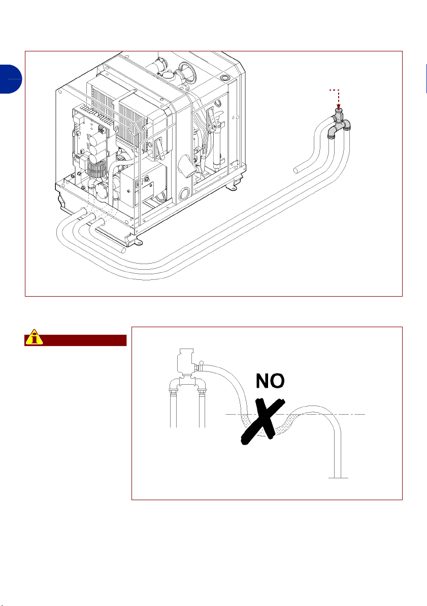
If the anti-siphon valve has to be fitted, install
it as shown in the figure.
GB
Important
Take care that water
does not stagnate in
the drainage pipe.
anti-siphon valve
IDM - 40200702500.tif
- 18 -
IDM - 40200702600.tif
User manual
C140200701.fm
Page 19
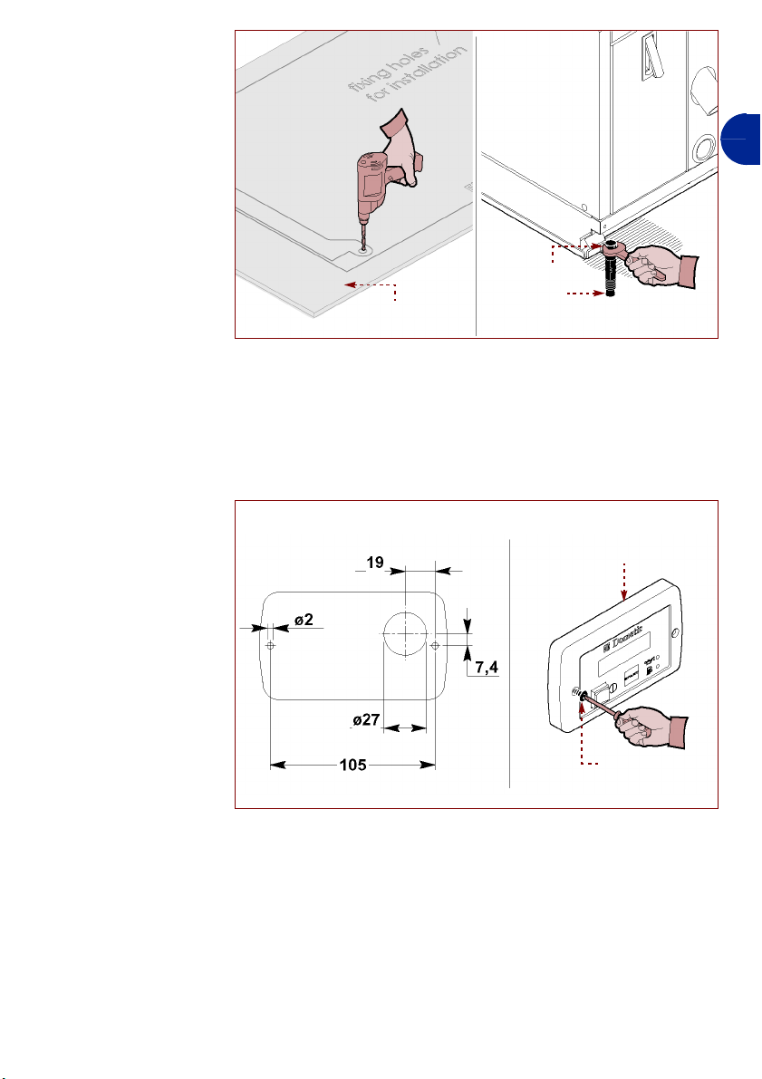
Proceed as indicated.
1 -Identify the exact po-
sition using the boring
template (A), supplied in the pack, and
drill the holes.
2 -Insert the plugs (B)
provided.
3 -Position the unit in the
set area.
4 -Fix the unit to the floor
using appropriate
screws (B).
5 -Identify the exact po-
sition and, if necessary, trace the
coordinates so as to
position the control
panel properly (C)
(see figure).
6 -Fix the control panel
(C) using the screws
(D) provided.
drilling
template (A)
GB
screw (C)
block (B)
IDM - 40200700800.tif
control panel (C)
screw (D)
IDM - 40200700900.tif
C140200701.fm
- 19 -
User manual
Page 20
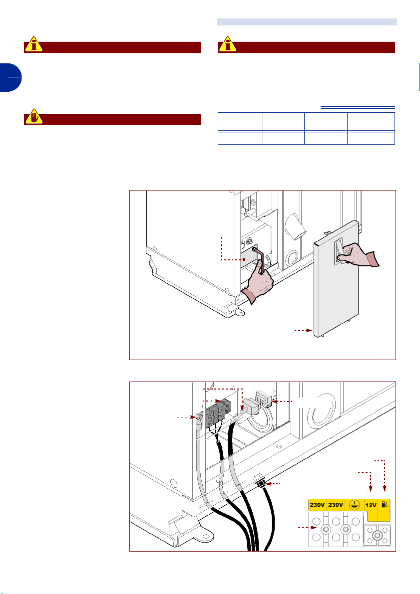
CONNECTION TO THE POWER SUPPLY
Important
The connection must be carried out by a
qualified, authorised technician, in com-
GB
pliance with current laws and using appropriate, prescribed materials.
Warning - Caution
Before carrying out any operation, turn the
main power supply off.
Proceed as indicated.
1 -Open the door (E).
2 -Unfasten the screws
to dismantle the casing (F).
3 -Use cables of the cor-
rect diameter (see
"Table of Cable Sections").
Important
Only connect the battery after having
made all the electrical connections.
Table of Cable Sections
L
12
(BATTERY
CHARGER)
door (E)
V
ENGTH UP TO 6 M
BATTERY CON-
(
NECTION)
casing (F)
230V
(POWER CABLES)
4 mm2 2.5 mm2 16 mm2 25 mm2
L
ENGTH OVER 6 M
BATTERY CONNEC-
(
TION)
4 -Connect the cable to
terminals (G) (230V
live and earth) on the
panelboard.
5 -Connect cable (H)
powering the control
panel to the socket (L).
6 -Connect the battery as
indicated in the following paragraphs.
7 -Replace the casing (F)
and fasten the screws.
8 -Close the door (E)
when the operation
has been completed.
terminals (G)
+ battery
cable (H)
- 20 -
intake (L)
fuel reserve indicator
battery charger
- battery
terminals
(G)
IDM - 40200701000.tif
C140200701.fm
User manual
Page 21

CONNECTING THE BATTERY CHARGER
The unit is set up to provide for automatic
battery recharging. If this function is to be
used, proceed as follows.
Use a cable of the section indicated in the table, and connect it to the relevant terminal on
the generator and to the positive terminal of
CONNECTING THE FUEL INDICATOR
Only use the indicator connection if there is a
fuel level probe in the tank used for the generator.
CONNECTING THE BATTERY
To start the generator it is necessary to use a
12VDC battery, with a minimum capacity of
60Ah.
Use regulation, sheathed cables, with the
section indicated in the table, and follow the
working order given below:
First connect the positive cable (+ ) of the battery to the terminal marked with the symbol
"+ " on the generator.
the battery to be charged.
If the battery to be charged is not the one
used to start the generator, the negative terminal of that battery must be connected to
the generator mass point.
Connect the proble cable (e.g. float) to the
relevant terminal (see figure above).
Then connect the negative cable (-) of the
battery to the terminal marked with the symbol "-" on the generator.
Protect the connections with specific grease.
It is advisable to use a 100A fuse, series fit-
ted in the vicinity of the starter battery positive terminal, so as to protect the unit system.
GB
ELECTRICAL CONNECTION TO THE EXTERNAL NETWORK
Important
To use electric power from the external
network, follow the instructions given below with care.
The on board electrical system must be fitted
with a relay or switch (e.g. Dometic switch
cod. AG113, available on request) to prevent
damage to the generator when the external
power supply network is connected; in this
case, it is suggested that the generator be
connected in such a way as to give it priority
with respect to the external network.
C140200701.fm
The electrical connection must be made in
compliance with current laws in the country of
use.
For proper installation by the end user, it is
recommended that you request the technical
assistance of the dealer or a specialist technician.
For the 230 V, use an approved cable with
the section indicated in the table. For connection of the Dometic switch cod. AG113 refer
to the instructions and diagram on the following pages.
- 21 -
User manual
Page 22
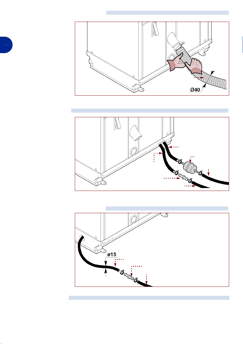
CONNECTION TO THE EXHAUST
Connect the exhaust pipe
(M) and lock it with an appropriate hose clamp.
GB
FUEL CONNECTION
1 -Connect the fuel sup-
ply pipe (N) to the filter (P) and lock it in
position with appropriate hose clamps.
2 -Connect the fuel dis-
charge pipe (Q) to the
connector (R) and
lock it in position with
appropriate hose
clamps.
pipe (Q)
connector (R)
pipe (M)
pipe (Q)
IDM - 40200701200.tif
pipe (N)
fuel filter (P)
pipe (N)
IDM - 40200701300.tif
COOLING WATER CONNECTION
Connect the water supply
pipes (S) using a connector (T) and lock them in
position with appropriate
hose clamps.
TESTING THE UNIT
The unit is tested in advance by the Manufacturer, and no particular operations need to be
carried out by the operator.
- 22 -
pipe (S)
connector
pipe (S)
IDM - 40200701400.tif
User manual
C140200701.fm
Page 23
INFORMATION ON ADJUSTMENTS
ADJUSTMENT METHOD
The main functions of the unit do not require
particular adjustments by specialist techni-
cians, with the exception of working adjustments carried out by the user.
INFORMATION ON USE
RECOMMENDATIONS FOR USE AND OPERATION
The appliance has been designed and built to
satisfy all the working conditions indicated by
the manufacturer. Tampering with any of the
devices in order to achieve performance lev-
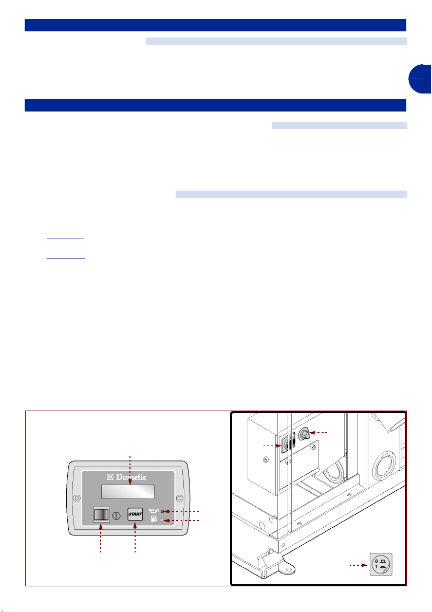
DESCRIPTION OF CONTROLS
A) Safety switch: Prepares the unit for
start-up or stops operation.
1) Position 1: the unit is powered by the battery
and is ready for start-up.
2) Position 0
B) Thermal micro-circuit breaker (12Vdc):
serves to restore power to the electrical
commands after the safety circuit has
been triggered.
Press button to restore power to the electrical controls.
: Shuts off all power to the unit.
els other than the ones foreseen may result
in risks for the health and safety of persons,
and in damage to property.
C) Starter switch: serves to enable and dis-
able the control panel and to turn the generator off.
D) Starter button: serves to turn the unit on.
E) Indicator (red light): indicates insuffi-
cient engine oil pressure
F) Indicator (orange light): Indicates that
the fuel level is low
G) Digital display: displays the working pa-
rameters and alarm messages.
GB
B
G
C140200701.fm
E
F
CD
- 23 -
A
A
IDM - 40200701500.tif
User manual
Page 24
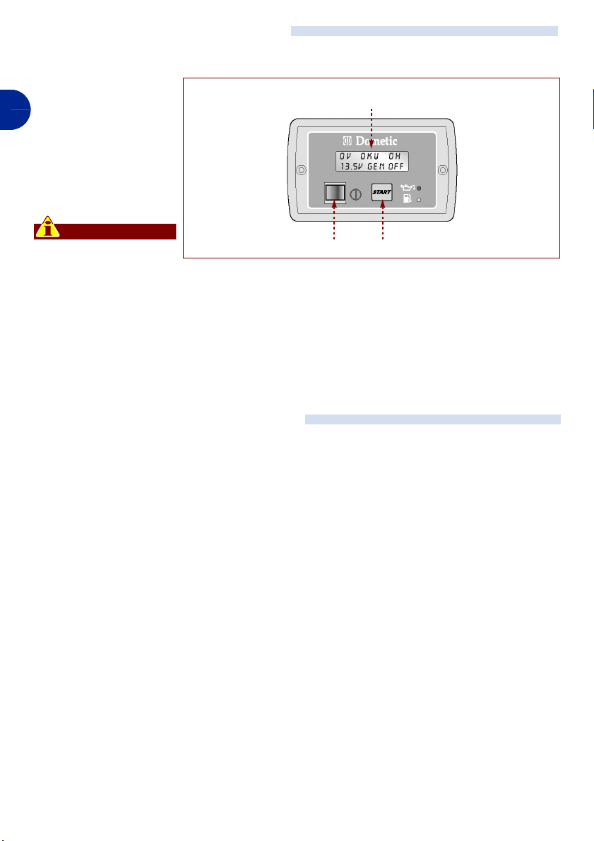
STARTING AND STOPPING THE UNIT
Proceed as indicated.
Starting
1 -Press the switch (C)
GB
to enable the power
supply to the controls.
2 -When the display (G)
indicates "GEN OFF",
press the button (D)
to start the unit.
Important
When the unit starts up
for the first time the water pump is empty. Keep on carrying out
the start-up operation for 4/5 seconds until the water pump starts to take in sea water (priming).
Stopping
1 -Press the switch (C) to turn the unit off.
PROLONGED INACTIVITY OF THE UNIT
In the event of prolonged inactivity of the unit,
a series of operations must be carried out to
guarantee proper operation when it is used
again.
– Drain the water circuit completely.
– Disconnect the battery.
– Turn the safety switch to the "0" (OFF) po-
sition
G
CD
IDM - 40200701600.tif
To restore the unit to operation after a period
of prolonged inactivity it is recommended that
you:
– Change the engine oil (see "Changing en-
gine oil" ).
– Change the fuel filter (see "Changing the
fuel filter").
– Change the sacrificial anode (see "Chang-
ing the sacrificial anode").
- 24 -
C140200701.fm
User manual
Page 25

MAINTENANCE INFORMATION
RECOMMENDATIONS FOR MAINTENANCE
Before carrying out any type of maintenance
operation, activate all the safety devices provided and evaluate whether or not those
working on the unit and those in the vicinity of
the unit should be informed. In particular,
TABLE OF MAINTENANCE OPERATIONS
Important
Keep the appliance in a state of maximum
efficiency, by carrying out the planned
maintenance operations foreseen by the
manufacturer. If these are properly car-
Action Daily
check the fuel and top up
clean the fuel filter
change the fuel filter
check that there are no leaks
check the state of the injector
check the fuel injector phases
check the fuel injection pump
check the lubricant level in the oil sump
change the lubricant oil
clean the oil filter
check that there are no oil leaks
adjust play in the inlet and outlet valves
check that delivery connector is tight
check pump rotor
clean and deoxidise metal parts
change the zinc anode
change the piston rings
X* = must be carried out by an authorised YANMAR dea ler or by qualified Dometic personnel..
C140200701.fm
X
X
after use
X
before use
X
after use
make sure that the surrounding area is clearly signed and prevent access to all the devices that might, if activated, result in
unexpected dangers or endanger the health
and safety of persons.
ried out, they will ensure the appliance
provides optimum performance, a longer
working life and constant compliance
with the safety requirements.
1st month
FIRST 50
hours
the first time
the first time
X
X*
every 3
months or
200 hours
X
X
2nd time and following
X
every 6
months or
400 hours
X
X*
X*
X*
2nd time and following
X*
X
yearly or
1000 hours
X*
X
X
X
GB
- 25 -
User manual
Page 26
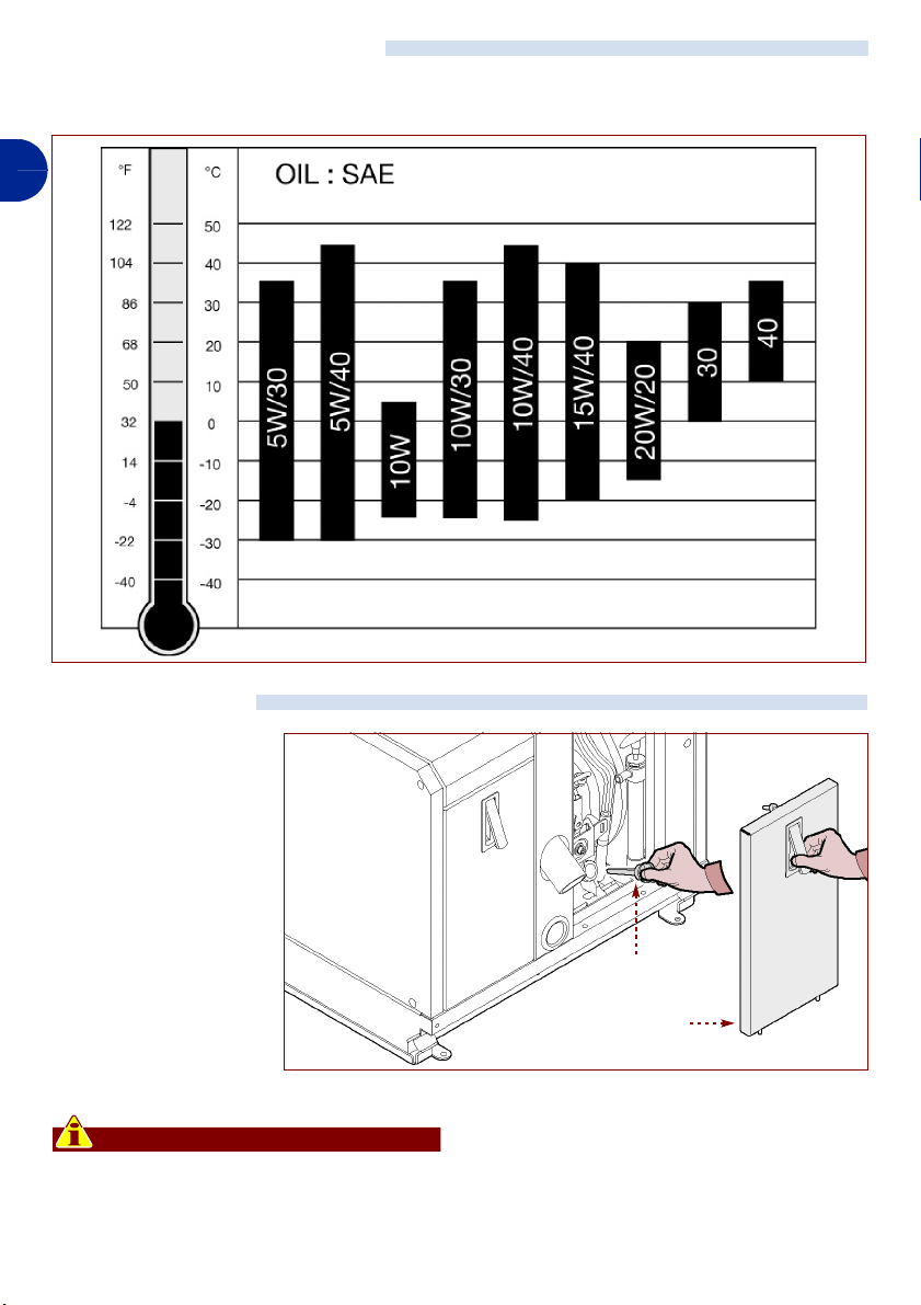
RECOMMENDED LUBRICANTS
Use oils and lubricants with characteristics
the same as those indicated in the table.
GB
IDM - 40200702700.tif
CHECK OIL LEVEL
Proceed as indicated.
1 -Turn the unit on and
allow it to warm up for
a few minutes.
2 -Turn the unit off.
3 -Wait for a few min-
utes to allow all the oil
to flow into the sump.
4 -Open the door (A).
5 -Extract the dipstick
(B) and check the oil
level; top up if neces-
sary. For the amounts
of oil, see "Technical data".
Important
The oil level must be between the minimum and maximum marks.
Do not mix oils with different characteristics or from different manufacturers.
rod (B)
door (A)
6 -Close the door (A) when the operation
has been completed.
- 26 -
IDM - 40200701700.tif
User manual
C140200701.fm
Page 27
CHANGING ENGINE OIL
Proceed as indicated.
1 -Turn the unit off.
2 -Leave the unit to cool
down sufficiently, to
avoid the risk of burn-
ing.
3 -Open the door (A).
4 -Provide a container of
sufficient capacity.
For the amounts of
oil, see "Technical da-
ta".
5 -Extract the dipstick
(B).
6 -Unfasten the screw
(C) to extract the pump (D).
7 -Adjust the pump man-
ually to drain all the oil
into the container.
8 -Replace the pump (D)
in its housing and fix it
with the screw (C).
9 -Pour in the new oil until
reaching the correct
level on the dipstick
(B) (see "Check oil
level").
10 -Replace the dipstick
(B).
11 -Close the door (A)
when the operation
has been completed.
C140200701.fm
12 -Turn the unit on and allow it to warm up
for a few minutes.
13 -Turn the unit off and check the oil level
(see "Check oil level").
rod (B)
door (A)
pump (D)
screw (C)
GB
pump (D)
IDM - 40200701800.tif
rod (B)
IDM - 40200701900.tif
Important
Do not discard used oil, but hand it over to
an authorised disposal organisation in
compliance with current local laws.
Use oils and lubricants of the types recommended by the manufacturer.
- 27 -
User manual
Page 28
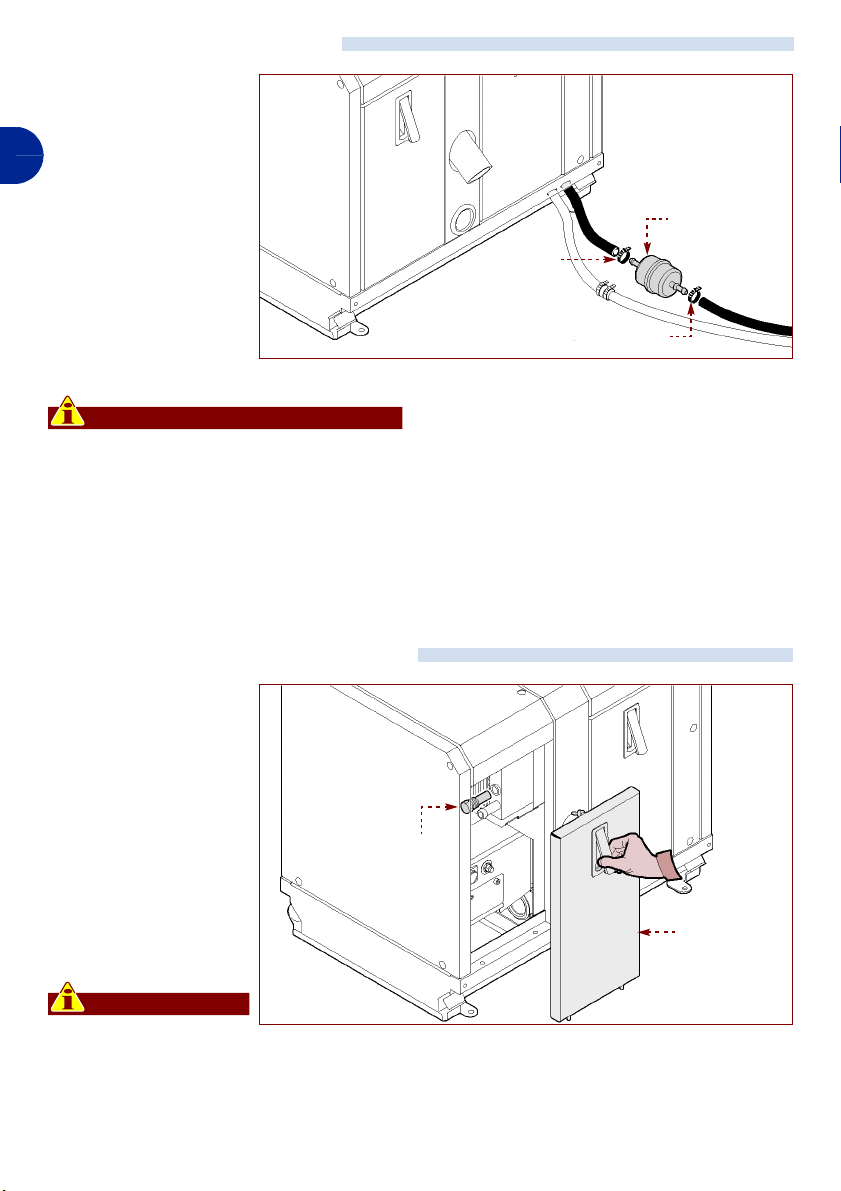
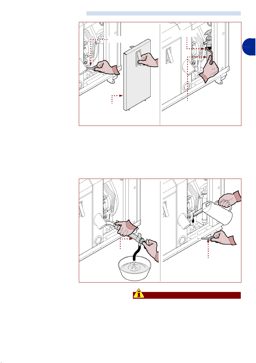
CHANGING THE FUEL FILTER
Proceed as indicated.
1 -Switch the appliance
off and leave it to
GB
cool.
2 -Provide a container to
catch any leaks.
3 -Loosen the hose
clamps (E).
4 -Remove the filter (F)
and replace it.
5 -Lock the hose clamps
(E) when you have
done this.
Important
Do not discard pollutants into the environment. They must be disposed of according to current laws.
tie (E)
tie (E)
fuel filter (F)
IDM - 40200702000.tif
CHANGING THE SACRIFICIAL ANODE
Proceed as indicated.
1 -Switch the appliance
off and leave it to
cool.
2 -Open the door (A).
3 -Unscrew the sacrifi-
cial anode (M) and re-
place it with a new
anode (M)
one.
4 -Close the door (A)
when the operation
has been completed.
Important
Do not discard pollutants into the environment. They must be
disposed of according to current laws.
- 28 -
door (A)
C140200701.fm
IDM - 40200702800.tif
User manual
Page 29

TROUBLESHOOTING INFORMATION
FINDING MALFUNCTIONS
The aim of the following information is to help
identify and correct any malfunctions and
problems that might occur during use. Some
of these problems may be solved by the user,
while for all the others specific technical
Problem Cause Remedy
When the starter button is
pressed the control panel does
not light up
When the starter button is
pressed the unit does not start
The starter motor turns, but the
unit does not start
The unit tends to shut down
C140200701.fm
The power cables are
disconnected or they do not
provide a continuous supply
Battery low Change the battery
The power cables are
disconnected or they do not
provide a continuous supply
The inverter is broken Contact the service department
The starter motor does not turn Contact the service department
electrical power disconnected
Battery low Change the battery
The power cables are
disconnected or they do not
provide a continuous supply
The inverter is broken Contact the service department
Malfunction in the pump power
supply
Engine malfunction Contact the service department
Injectors dirty or faulty Contact the service department
Cooling air/water pipe blocked
Sea water pump rotor worn
The inverter is broken Contact the service department
Malfunction in the pump power
supply
Injectors dirty or faulty Contact the service department
Air filter blocked Clean the air filter
Cooling air/water pipe blocked
Oil level too high
Sea water pump rotor worn
Voltage required higher than 3,5
kW
knowledge or abilities are required, so that
they must only be carried out by qualified
technicians of proven experience in the specific field of operation.
Contact the service department
Contact the service department
Press the restore button to
reconnect the electrical power.
Contact the service department
Contact the service department
Check the cooling air/water pipe
and clean it if necessary
Replace the rotor (see “Changing
the water pump rotor”)
Contact the service department
Check the cooling air/water pipe
and clean it if necessary
Check the oil level, and remove
excess oil if necessary (see “Check
oil level”)
Replace the rotor (see “Changing
the water pump rotor”)
Decrease the required voltage load
GB
- 29 -
User manual
Page 30
Problem Cause Remedy
The power cables are
The unit is not delivering power
The unit starts and accelerates
GB
strongly, then stops and the
message "generator alert" is
displayed
The power supplied is not
constant
disconnected or they do not
provide a continuous supply
The inverter is broken Contact the service department
The inverter is broken Contact the service department
The inverter is broken Contact the service department
Malfunction in the pump power
supply
The power cables are
disconnected or they do not
provide a continuous supply
Injectors dirty or faulty Contact the service department
Air filter blocked Clean the air filter
Cooling air/water pipe blocked
Voltage required higher than 3,5
kW
TABLE OF ALARM SIGNALS
If the problem or malfunction encountered is
not listed in the table, you should check the
Alarm Problem Remedy
LOW BATTERY Battery low Change the battery
OIL CHANGE
NO FUEL Fuel level too low Fill up with fuel
OIL TEMP PRESS
Indicates that it is necessary to
change the engine oil
Insufficient oil in engine Top up with oil of the same type
Exhaust gas temperature too high
"Alarm signals" table given below.
Change the engine oil (see “Changing
engine oil”)
On restarting the unit, keep the start
switch pressed for a long time to
reset the hour counter.
Check the cooling air/water pipe and
clean it if necessary
See “Finding malfunctions”
Contact the service department
Contact the service department
Contact the service department
Check the cooling air/water pipe
and clean it if necessary
Decrease the required voltage load
Important
GENERATOR ALERT! General alarm
OVERLOAD! Voltage required higher than 3,5 kW Decrease the required load
SHORT CIRCUIT Output cable short-ircuit Eliminate the short-circuit
OVER TEMPERATURE Inverter overheating
LOW POWER ENGINE Engine revs too low Decrease the required load
Important
If the problem persists, contact the
service department
Switch the appliance off and leave it to
cool.
- 30 -
C140200701.fm
User manual
Page 31

Alarm Problem Remedy
RESTART GEN? Unit overheating
GEN CAL
GEN WAIT The unit is paused before starting
GEN ON Unit running
GEN OFF Unit off or ready for START
The unit is performing automatic setup prior to starting
Switch the appliance off and leave it to
cool.
Wait until the operation has ended
then start the unit
Wait until the operation has ended
then start the unit
INFORMATION ON SPARE PARTS
RECOMMENDATIONS WHEN CHANGING PARTS
Before replacing any parts, activate all the
safety devices provided and evaluate the
need to inform the persons working on the
machine and any persons in the vicinity.
In particular, make sure that the surrounding
areas are adequately marked and prevent
access to any of the devices that might, if active, result in unexpected dangers and risks
to the health and safety of persons. Should it
be necessary to change worn components,
only use original spare parts.
The manufacturer will not be liable for any
damage to persons or components deriving
from the use of non-original spare parts and
from repairs carried out without the authorisation of the manufacturer.
GB
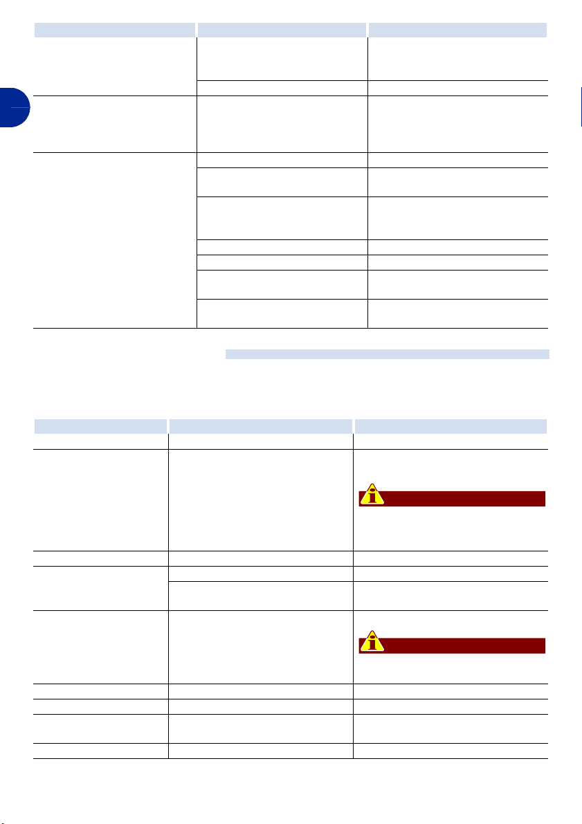
CHANGING THE WATER PUMP ROTOR
Proceed as indicated.
1 -Switch the appliance
off and leave it to
cool.
2 -Unfasten the screws
to dismantle the cas-
ing (M).
3 -Unfasten the screws
to remove the cover
C140200701.fm
(N).
4 -Extract and replace
the rotor (P).
5 -Fit the cover (N) and
fix it with the screws.
6 -Fit the casing (M) and fix it with the
casing (M)
- 31 -
rotor (P)
cover (N)
IDM - 40200702200.tif
screws when this operation has been
completed.
User manual
Page 32

DECOMMISSIONING THE UNIT
When decommissioning, leave the unit, disconnected from the power supply, in a suitable area so that it will not get in the way and
will not be within easy access of unauthor-
GB
ised persons.
The unit must be disposed of by experienced
operators, in compliance with current regula-
tions regarding safety at work.
When decommissioning, the various types of
material, such as electrical and electronic
components, must be separated and disposed of according to law.
- 32 -
C140200701.fm
User manual
Page 33

WIRING DIAGRAM
GB
DESCRIPTION
1 THREE PHASE COIL
2 AUXILIARY COIL
3 AUXILIARY COIL
4 INVERTER MODULE
5 9 PIN CONNECTOR
6 12V REGULATOR
7 EMERGENCY SWITCH 0/1
8 PRESSURE SWITCH
9 STARTER RELAY
10 STARTER MOTOR
11 9 PIN CONNECTOR
12 INTERNAL CONTROL PANEL
13 THERMAL CUTOUT
14 INTERFACE MODULE
15 ELECTROSTOP
16 12 PIN CONNECTOR
17 TEMPERATURE PROBE
18 2 PIN CONNECTOR
19 CABIN CONTROL PANEL
20 12 PIN CONNECTOR
21 AUXILIARY COIL
22 CYLINDRICAL COUPLING CONNECTOR
23 PUMP RELAY
24 ENGINE STARTER RELAY
25 4 PIN CONNECTOR
26 6 PIN CONNECTOR
C140200701.fm
- 33 -
User manual
Page 34

GB
CONNECTION TO THE EXTERNAL POWER SUPPLY
AG113 switching accessory (available on demand)
1) Use cables of suitable section (see table in paragraph "electrical connection")
2) Fix the AG113 switch in a position that facilitates connection.
3) Break the cable connecting the mains input with the cut-out on the control
panel, so that it is possible to make the connections as shown in the wiring
diagram.
4) Connect the cables to the switch, it is necessary to insert a jumper between
terminal 1 and R1 and between terminal 3 and R3.
5) In positions R2 and R4, connect the cables from the generator 230 V terminal
board.
User
External
socket
Battery
- 34 -
AG113 switch
Generator
C140200701.fm
User manual
Page 35

Page 36

© DOMETIC - 2006 Tutti i diritti riservati - Stampato in Italia Realizzato da IDM
Nessuna parte di questo manuale può essere riprodotta, copiata o
divulgata con qualsiasi mezzo senza l'autorizzazione scritta della
DOMETIC
Le figure, le descrizioni, i riferimenti ed i dati tecnici contenuti nel
presente manuale sono indicativi e non impegnativi.
La DOMETIC si riserva il diritto di apportare in qualsiasi momento
e senza preavviso tutte le modifiche che riterrà opportuno, nella
costante ricerca di migliorare la qualità e la sicurezza, senza
impegnarsi ad aggiornare di volta in volta questo manuale.
© 2006 - Autore dei testi: IDM esperti in comunicazione tecnica Forlì - I testi possono essere riprodotti, integralmente o
parzialmente, purché venga citato l’autore.
Conservare questo documento per futuri riferimenti.
Page 37

SOMMARIO
INFORMAZIONI GENERALI...............................6
INFORMAZIONI TECNICHE ............................... 8
INFORMAZIONI SULLA SICUREZZA..............11
INFORMAZIONI SULLA MOVIMENTAZIONE
E INSTALLAZIONE .......................................... 15
INFORMAZIONI SULLE REGOLAZIONI.......... 23
INFORMAZIONI SULL'USO............................. 23
INFORMAZIONI SULLA MANUTENZIONE ..... 25
INFORMAZIONI SUI GUASTI .......................... 29
INFORMAZIONI SULLE SOSTITUZIONI ......... 31
SCHEMA ELETTRICO ..................................... 33
INDICE ANALITICO
A
Accensione e spegnimento apparecchiatura
Acqua di raffreddamento, allacciamento (22)
Allacciamento acqua di raffreddamento (22)
Allacciamento elettrico (20)
Allacciamento gasolio (22)
Allacciamento scarico fumi (22)
Anodo sacrificale, cambio (28)
Apparecchiatura e costruttore, identificazione (6)
Apparecchiatura, collaudo (22)
Apparecchiatura, descrizione generale (8)
Apparecchiatura, dismissione (32)
Apparecchiatura, inattività prolungata (24)
Apparecchiatura, installazione (16)
Assistenza, modalità di richiesta (7)
C
Cambio anodo sacrificale
Cambio filtro combustibile (28)
Cambio olio motore (27)
Carico e trasporto (15)
Collaudo apparecchiatura (22)
Comandi, descrizione (23)
Controllo livello olio (26)
Costruttore e apparecchiatura, identificazione (6)
D
Dati tecnici
Deposito, modalità di (16)
Descrizione comandi (23)
Descrizione generale apparecchiatura (8)
Disimballo e imballo (15)
Dismissione apparecchiatura (32)
Dispositivi di sicurezza (10)
F
Filtro combustibile, cambio
Funzionamento e l’uso, norme per (12)
Funzionamento e uso, raccomandazioni (23)
G
Glossario e terminologie
Guasti, ricerca (29)
I
Identificazione costruttore e apparecchiatura
Imballo e disimballo (15)
Inattività prolungata dell'apparecchiatura (24)
Informazione e sicurezza, segnali di (14)
C140200701.fm
Installazione apparecchiatura (16)
Installazione e movimentazione, raccomandazioni per
la
Intervalli di manutenzione, tabella (25)
L
Livello olio, controllo
Lubrificanti consigliati (26)
M
Manuale, scopo del
(9)
(15)
(28)
(28)
(7)
(26)
(6)
(24)
(6)
Manutenzione, raccomandazioni per la (25)
Manutenzione, tabella intervalli di (25)
Modalità di deposito (16)
Modalità di richiesta assistenza (7)
Modalità per le regolazioni (23)
Movimentazione e installazione, raccomandazioni per
(15)
la
Movimentazione e l’installazione, norme per (11)
Movimentazione e sollevamento (16)
N
Norme generali
Norme per il funzionamento e l’uso (12)
Norme per la movimentazione e l’installazione (11)
Norme per la sicurezza sull’impatto ambientale (13), (21)
Norme per le regolazioni e la manutenzione (12)
O
Olio motore, cambio
Organi principali (8)
P
Pompa acqua, sostituzione girante
R
Raccomandazioni per l'uso e funzionamento
Raccomandazioni per la manutenzione (25)
Raccomandazioni per la movimentazione e
installazione
Raccomandazioni per la sostituzione parti (31)
Regolazioni e la manutenzione, norme per (12)
Ricerca guasti (29)
Richiesta assistenza, modalità di (7)
S
Scarico fumi, allacciamento
Scopo del manuale (6)
Segnali di sicurezza e informazione (14)
Sicurezza e informazione, segnali di (14)
Sicurezza per lo smaltimento di Rifiuti di Apparecchiature
Elettriche ed Elettroniche (Direttiva RAEE 2002/96)
(21)
Sicurezza sull’impatto ambientale, norme per (13), (21)
Sicurezza, dispositivi di (10)
Smaltimento di Rifiuti di Apparecchiature Elettriche ed
Elettroniche (Direttiva RAEE 2002/96), sicurezza
Sollevamento e movimentazione (16)
Sostituzione girante pompa acqua (31)
Sostituzione parti, raccomandazioni per la (31)
Spegnimento e accensione apparecchiatura (24)
T
Tabella intervalli di manutenzione
Tabella segnalazione allarmi (30)
Terminologie e glossario (7)
Trasporto e carico (15)
U
Usi impropri
Uso e funzionamento, raccomandazioni (23)
- 5 -
(11)
(27)
(31)
(15)
(22)
(25)
(10)
Manuale d’uso
I
(23)
(13),
(13), (21)
Page 38

INFORMAZIONI GENERALI
SCOPO DEL MANUALE
Questo manuale, che è parte integrante
dell'apparecchiatura, è stato realizzato dal
costruttore per fornire le informazioni necessarie a coloro che sono addestrati e autorizzati ad interagire con essa nell'arco della sua
vita prevista.
I
Queste informazioni sono fornite dal Costruttore nella propria lingua originale (italiano) e
possono essere tradotte in altre lingue per
soddisfare le esigenze legislative e/o commerciali.
Oltre ad adottare una buona tecnica di utilizzo, i destinatari delle informazioni devono
leggerle attentamente ed applicarle in modo
rigoroso.
Un po' di tempo dedicato alla lettura di tali informazioni permetterà di evitare rischi alla
salute e alla sicurezza delle persone e danni
economici.
Nel caso in cui, in questo manuale, vi siano
delle informazioni supplementari rispetto
all'effettivo allestimento dell'apparecchiatura,
esse non interferiscono con la lettura.
Conservare questo manuale per tutta la durata di vita dell'apparecchiatura in un luogo
noto e facilmente accessibile, per averlo
sempre a disposizione nel momento in cui è
necessario consultarlo.
Il costruttore si riserva il diritto di apportare
modifiche senza l'obbligo di fornire preventivamente alcuna comunicazione.
Per evidenziare alcune parti di testo di rilevante importanza o per indicare alcune specifiche importanti, sono stati adottati alcuni
simboli il cui significato viene di seguito descritto.
Pericolo - Attenzione
Indica situazioni di grave pericolo che, se
trascurate, possono mettere seriamente a
rischio la salute e la sicurezza delle persone.
Cautela - Avvertenza
Indica che è necessario adottare comportamenti adeguati per non mettere a rischio
la salute e la sicurezza delle persone e non
provocare danni economici.
Importante
Indica informazioni tecniche di particolare importanza da non trascurare.
IDENTIFICAZIONE COSTRUTTORE E APPARECCHIATURA
La targhetta di identificazione raffigurata è appli-
A
cata direttamente
sull'apparecchiatura.
A) Identificazione co-
B
struttore
B) Marcature di confor-
mità
C) Modello/Numero di
matricola
C
D
E
D) Anno di costruzione
E) Dati tecnici
- 6 -
C140200701.fm
IDM - 40200700100.tif
Manuale d’uso
Page 39

GLOSSARIO E TERMINOLOGIE
Vengono descritti alcuni termini ricorrenti
all'interno del manuale in modo da fornire
una visione più completa del loro significato.
Installatore: tecnico scelto e autorizzato dal
Costruttore o dal suo mandatario, fra coloro
che hanno i requisiti per eseguire l'installazione ed il collaudo dell'apparecchiatura.
Manutenzione ordinaria: insieme delle operazioni necessarie a conservare la conveniente funzionalità ed efficienza
dell'apparecchiatura. Normalmente queste
operazioni vengono programmate dal Costruttore che definisce le competenze necessarie e le modalità di intervento.
MODALITÀ DI RICHIESTA ASSISTENZA
Per qualsiasi esigenza rivolgersi al Servizio
Assistenza del costruttore.
Manutenzione straordinaria: insieme delle
operazioni necessarie a conservare la conveniente funzionalità ed efficienza dell'apparecchiatura. Queste operazioni non sono
programmate dal Costruttore e devono essere eseguite dal manutentore.
Manutentore esperto: tecnico scelto ed autorizzato dal costruttore fra coloro che hanno
i requisiti, le competenze e le informazioni
per eseguire interventi di riparazione e manutenzione straordinaria sull'apparecchiatura.
Per ogni richiesta di assistenza tecnica, indicare i dati riportati sulla targhetta di identificazione, le ore approssimative di utilizzo e il
tipo di difetto riscontrato.
I
C140200701.fm
- 7 -
Manuale d’uso
Page 40

INFORMAZIONI TECNICHE
DESCRIZIONE GENERALE APPARECCHIATURA
Il gruppo elettrogeno per imbarcazioni “BLUTEC 40 D”, è un'apparecchiatura progettata
e costruita per essere installata entrobordo
su natanti.
Viene impiegata nel settore della nautica pro-
fessionale e civile per generare corrente sulle
imbarcazioni da diporto.
L'apparecchiatura è dotata di un quadro comandi da dove è possibile controllare tutte le
funzioni operative.
I
ORGANI PRINCIPALI
– Motore endotermico (A): per fornire
energia a tutti gli organi principali.
– Alternatore (B): trasforma l'energia mec-
canica del motore in energia elettrica a
corrente alternata.
– Scambiatore di calore (C): raffredda
l'aria all'interno dell'apparecchiatura attraverso lo scambio termico con l'acqua marina.
scambiatore di calore (C)
– Pompa acqua (D): alimenta il circuito di
– Inverter (E): converte la tensione che lo
– Quadro comandi (F): comprende i dispo-
raffreddamento acqua marina
alimenta in una tensione di qualità superiore di 230V/50Hz perfettamente stabile.
sitivi per attivare e controllare tutte le funzioni operative
quadro comandi (F)
alternatore (B)
pompa acqua (D)
inverter (E)
- 8 -
C140200701.fm
motore endotermico (A)
IDM - 40200700200.tif
Manuale d’uso
Page 41

DATI TECNICI
IDM - 40200700300.tif
Modello apparecchiatura Unità di misura BLUTEC 40D
Dimensioni
A mm 570
B mm 406
C mm 528
Peso kg 85
Dati tecnici motore
Modello YANMAR L 70 N / 320cc
Potenza massima HP 6,1
Regime massimo di esercizio giri/min 3300
Consumo combustibile lt 1,3
Capacità coppa olio lt 1,1
Inclinazioni consentite ± 20°
Dati tecnici generatore
Potenza elettrica massima in uscita (continua) W 3500
Tensione in uscita V 230±10%
Frequenza Hz 50
Classe di isolamento H
I
C140200701.fm
- 9 -
Manuale d’uso
Page 42

DISPOSITIVI DI SICUREZZA
L'illustrazione indica la posizione dei dispositivi.
– Riparo fisso (A): impedisce l'accesso agli
organi in movimento dell'apparecchiatura.
Può essere aperto solo con un'azione volontaria e con l'ausilio di un utensile.
I
sensore (C)
riparo fisso (A)
– Riparo mobile (B): impedisce l'accesso
all'interno dell'apparecchiatura.
– Sensore temperatura (C): disattiva l'ap-
parecchiatura in caso di temperatura troppo elevata dei gas di scarico.
riparo fisso (A)
USI IMPROPRI
Qualsiasi utilizzo diverso da quello autorizzato è da considerarsi USO IMPROPRIO.
riparo mobile (B)
È assolutamente vietato l'uso di questa
apparecchiatura in ambienti esplosivi o
esposti agli agenti atmosferici.
- 10 -
Manuale d’uso
IDM - 40200700400.tif
C140200701.fm
Page 43

INFORMAZIONI SULLA SICUREZZA
NORME GENERALI
– Il costruttore, in fase di progettazione e co-
struzione, ha posto particolare attenzione
agli aspetti che possono provocare rischi
alla sicurezza e alla salute delle persone che
interagiscono con l'apparecchiatura. Oltre al
rispetto delle leggi vigenti in materia, egli ha
adottato tutte le “regole della buona tecnica
di costruzione”. Scopo di queste informazioni è quello di sensibilizzare gli utenti a porre
particolare attenzione per prevenire qualsiasi rischio. La prudenza è comunque insostituibile. La sicurezza è anche nelle mani di
tutti gli operatori che interagiscono con l'apparecchiatura.
– Leggere attentamente le istruzioni riportate
nel manuale in dotazione e quelle applicate
direttamente, in particolare rispettare quelle riguardanti la sicurezza. Un po' di tempo
dedicato alla lettura risparmierà spiacevoli
incidenti; è sempre troppo tardi ricordarsi di
quello che si sarebbe dovuto fare quando
ciò è già accaduto.
– Prestare attenzione al significato dei sim-
boli delle targhette applicate; la loro forma
e colore sono significativi ai fini della sicurezza. Mantenerle leggibili e rispettare le informazioni indicate.
– Non manomettere, non eludere, non elimi-
nare o bypassare i dispositivi di sicurezza
installati. Il mancato rispetto di questo requisito può recare rischi gravi per la sicurezza e la salute delle persone.
– Il personale che effettua qualsiasi tipo di in-
tervento in tutto l'arco di vita dell'apparecchiatura, deve possedere precise
competenze tecniche, particolari capacità
ed esperienze acquisite e riconosciute nel
settore specifico. La mancanza di questi requisiti può causare danni alla sicurezza e
alla salute delle persone.
– In fase d'esercizio utilizzare solo gli indu-
menti e/o i dispositivi di protezione individuali indicati nelle istruzioni per l'uso fornite
dal costruttore e quelli previsti dalle leggi vigenti in materia di sicurezza sul lavoro.
– Durante il normale uso o per qualsiasi inter-
vento, mantenere gli spazi perimetrali, in
particolare quelli d'accesso ai comandi, in
condizioni adeguate per non causare rischi
alla sicurezza e alla salute delle persone.
– Ogni intervento, salvo quando espressa-
mente indicato, va eseguito a motore spento e adeguatamente raffreddato per evitare
rischi di scottature.
I
NORME PER LA MOVIMENTAZIONE E L'INSTALLAZIONE
– Eseguire il sollevamento e la movimenta-
zione nel rispetto delle informazioni fornite
dal costruttore e riportate direttamente
sull'imballo, sull'apparecchiatura e nelle
istruzioni per l'uso.
– Il personale che effettua il carico, lo scarico
e la movimentazione dell'apparecchiatura,
C140200701.fm
deve possedere capacità ed esperienza
acquisita e riconosciuta nel settore specifico e deve avere la padronanza dei mezzi di
sollevamento da utilizzare.
– Il carico ed il trasporto devono essere ese-
guiti con mezzi di portata adeguata, mediante l'ancoraggio dell'apparecchiatura
nei punti previsti dal costruttore. Chi è autorizzato ad effettuare tali operazioni dovrà
possedere specifiche capacità ed esperienza, al fine di salvaguardare la propria sicurezza e quella delle persone coinvolte.
– Tutte le fasi di installazione devono essere
considerate, sin dalla realizzazione del progetto generale. Prima di iniziare tali fasi, oltre alla definizione della zona di
installazione, colui che è autorizzato ad
eseguire queste operazioni dovrà, se necessario, attuare un “piano di sicurezza”
per salvaguardare l'incolumità delle persone direttamente coinvolte ed applicare in
- 11 -
Manuale d’uso
Page 44

modo rigoroso tutte le leggi, con particolare
riferimento a quelle sui cantieri mobili.
– È necessario accertarsi che la zona di installa-
zione sia predisposta per tutti gli allacciamenti
di aspirazione, alimentazione e scarico.
– In fase di installazione, rispettare gli spazi
perimetrali indicati dal costruttore, anche in
considerazione di tutte le attività lavorative
I
circostanti. L'attuazione di questo requisito
va effettuata anche nel rispetto delle leggi
vigenti in materia di sicurezza sul lavoro.
NORME PER IL FUNZIONAMENTO E L'USO
– L'operatore, oltre ad essere opportuna-
mente addestrato e documentato sull'uso
dell'apparecchiatura, deve possedere capacità e competenze adeguate al tipo di attività lavorativa da svolgere.
– Anche dopo essersi documentati opportu-
namente, al primo uso, se necessario, simulare alcune manovre di prova per
individuare i comandi e le loro funzioni principali, in particolare quelle relative all'avviamento ed all'arresto.
– Utilizzare l'apparecchiatura solo per gli usi
previsti dal fabbricante. L'impiego dell'apparecchiatura per usi impropri può recare
– L'installazione e gli allacciamenti vanno
eseguiti secondo le indicazioni fornite dal
costruttore. Il responsabile dovrà tener
conto anche di tutti i requisiti normativi e legislativi ed eseguire tutte le operazioni di installazione ed allacciamento a regola
d'arte. Ad installazione completata, prima
delle fasi d'uso, egli dovrà verificare, attraverso un controllo generale, se tali requisiti
sono stati rispettati.
rischi per la sicurezza e la salute delle persone e danni economici.
– L'apparecchiatura è stata progettata e co-
struita per soddisfare tutte le condizioni
operative indicate dal costruttore. Manomettere qualsiasi dispositivo per ottenere
prestazioni diverse da quelle previste può
comportare rischi per la sicurezza e la salute delle persone e danni economici.
– Non utilizzare l'apparecchiatura con i disposi-
tivi di sicurezza non perfettamente installati
ed efficienti. Il mancato rispetto di questo requisito può comportare rischi gravi per la sicurezza e la salute delle persone.
NORME PER LE REGOLAZIONI E LA MANUTENZIONE
– Mantenere l'apparecchiatura in condizioni di
massima efficienza, grazie alle operazioni di
manutenzione programmata previste dal costruttore. Se ben effettuata, essa consentirà
di ottenere le migliori prestazioni, una più lunga durata di esercizio ed un mantenimento
costante dei requisiti di sicurezza.
– Prima di effettuare qualsiasi intervento di
manutenzione e regolazione, attivare tutti i
dispositivi di sicurezza previsti e valutare la
necessità di informare il personale che opera e quello nelle vicinanze. In particolare,
segnalare adeguatamente le zone limitrofe
ed impedire l'accesso a tutti i dispositivi che
potrebbero, se attivati, provocare condizioni di pericolo inatteso e di rischio per la sicurezza e la salute delle persone.
– Gli interventi di manutenzione e regolazio-
ne devono essere eseguiti da persone autorizzate che dovranno predisporre tutte le
condizioni di sicurezza necessarie ed attenersi alle procedure indicate.
– Tutti gli interventi di manutenzione che richie-
dono una precisa competenza tecnica o particolari capacità devono essere eseguiti
esclusivamente da personale qualificato, con
esperienza riconosciuta e acquisita nel settore specifico di intervento.
– Per eseguire interventi di manutenzione in
zone non facilmente accessibili o pericolose, predisporre adeguate condizioni di sicurezza per se stessi e per gli altri, nel
pieno rispetto delle leggi vigenti in materia
di sicurezza sul lavoro.
- 12 -
C140200701.fm
Manuale d’uso
Page 45

– Sostituire i particolari troppo usurati con ri-
cambi originali. Usare gli oli e i grassi indicati nel manuale. Tutto questo potrà
assicurare la funzionalità della macchina
ed il livello di sicurezza previsto.
– Non disperdere materiale inquinante
nell'ambiente. Effettuare lo smaltimento nel
rispetto delle leggi vigenti in materia.
NORME PER LA SICUREZZA SULL'IMPATTO AMBIENTALE
Ogni organizzazione ha il compito di applicare delle procedure per individuare, valutare e
controllare l'influenza che le proprie attività
(prodotti, servizi, ecc.) hanno sull'ambiente.
Le procedure da seguire per identificare impatti significativi sull'ambiente devono tener
conto dei seguenti fattori:
– Emissioni nell'atmosfera
– Scarichi dei liquidi
– Gestione dei rifiuti
– Contaminazione del suolo
– Uso delle materie prime e delle risorse na-
turali
– Problematiche locali relative all'impatto am-
bientale
Allo scopo di minimizzare l'impatto ambientale, il costruttore fornisce, di seguito, alcune
indicazioni che dovranno essere tenute in
considerazione da tutti coloro che, a qualunque titolo, interagiscono con l'apparecchiatura nell'arco della sua vita prevista.
– Tutti i componenti di imballo vanno smaltiti
secondo le leggi vigenti nel paese in cui lo
smaltimento viene effettuato.
– In fase di installazione, fare in modo che
l'ambiente abbia un adeguato ricambio
d'aria per evitare la concentrazione di aria
insalubre per gli operatori.
– In fase d'uso e manutenzione, evitare di di-
sperdere nell'ambiente prodotti inquinanti
(oli, grassi, ecc.) e provvedere allo smaltimento differenziato in funzione della composizione dei diversi materiali e nel rispetto
delle leggi vigenti in materia. In caso di
componenti elettrici ed elettronici provvedere allo smaltimento come rifiuti speciali.
– Mantenere la rumorosità ai livelli minimi per
ridurre l'inquinamento acustico.
– In fase di dismissione, selezionare tutti i
componenti in funzione delle loro caratteristiche chimiche e provvedere allo smaltimento differenziato.
I
SICUREZZA PER LO SMALTIMENTO DI RIFIUTI DI APPARECCHIATURE
ELETTRICHE ED ELETTRONICHE (DIRETTIVA RAEE 2002/96)
– I Rifiuti di Apparecchiature Elettriche ed
Elettroniche possono contenere sostanze
pericolose con effetti potenzialmente nocivi
sull'ambiente e sulla salute delle persone.
Si raccomanda di effettuare lo smaltimento
in modo corretto.
– In fase di dismissione, selezionare tutti i
C140200701.fm
componenti in funzione delle loro caratteristiche chimiche e provvedere allo smaltimento differenziato nel rispetto delle leggi
vigenti in materia.
– In riferimento alla direttiva RAEE (Rifiuti
Apparecchiature Elettriche Elettroniche),
l'utilizzatore, in fase di dismissione, deve
separare i componenti elettrici ed elettronici e smaltirli negli appositi centri di raccolta
autorizzati, oppure riconsegnarli ancora installati al venditore all'atto di un nuovo acquisto.
– Tutti i componenti, che devono essere se-
parati e smaltiti in modo specifico, sono
contrassegnati da un apposito segnale.
– Lo smaltimento abusivo dei Rifiuti Apparec-
chiature Elettriche Elettroniche (RAEE) è
punito con sanzioni regolate dalle leggi vigenti nel territorio in cui viene accertata l'infrazione.
- 13 -
Manuale d’uso
Page 46

– In attuazione alle direttive europee (2002/
95/CE, 2002/96/CE, 2003/108/CE) in territorio italiano, ad esempio, è stato emanato
un decreto legislativo (n. 151 del 25 luglio
SEGNALI DI SICUREZZA E INFORMAZIONE
L'illustrazione indica la posizione dei segnali
applicati sull'apparecchiatura.
I
2005) che prevede una sanzione amministrativa pecuniaria di 2000÷5000 €.
IDM - 40200702400.tif
Obbligo di lettura del manuale
d'uso: l'operatore deve leggere
Pericolo di scottatura: fare at-
tenzione alle superfici calde.
e comprendere tutto il contenuto
del documento per conoscere i
comandi e tutte funzioni della
macchina. Tenere il documento
sempre a portata di mano.
Pericolo di folgorazione: non
C140200701.fm
accedere all'interno di elementi
in tensione.
- 14 -
Manuale d’uso
Page 47

INFORMAZIONI SULLA MOVIMENTAZIONE E INSTALLAZIONE
RACCOMANDAZIONI PER LA MOVIMENTAZIONE E INSTALLAZIONE
Eseguire la movimentazione e l'installazione
nel rispetto delle informazioni fornite dal costruttore e riportate direttamente sull'imballo
e nelle istruzioni per l'uso. Chi è autorizzato
IMBALLO E DISIMBALLO
L'imballo è realizzato,
con contenimento degli
ingombri, anche in funzione del tipo di trasporto
adottato.
Per facilitare il trasporto,
la spedizione può essere
eseguita con alcuni componenti smontati ed opportunamente protetti e
imballati.
Alcune parti, in particolare quelle elettriche, vengono protette con
nylon antiumidità.
Sull'imballo sono riportate tutte le informazioni necessarie ad effettuare il carico e lo scarico.
In fase di disimballo, controllare l'integrità e
l'esatta quantità dei componenti.
ad eseguire queste operazioni dovrà, se necessario, organizzare un “piano di sicurezza”
per salvaguardare l'incolumità delle persone
direttamente coinvolte.
A B
Il materiale di imballo va opportunamente
smaltito nel rispetto delle leggi vigenti.
L'imballo può essere realizzato:
A) su bancale con scatola in cartone
B) in cassa (per trasporto terrestre o aereo)
I
IDM - 40200700400.tif
CARICO E TRASPORTO
Il carico ed il trasporto, in funzione anche del
luogo di destinazione, possono essere effettuati con mezzi diversi.
Lo schema raffigura le soluzioni più utilizzate.
In fase di trasporto, al fine di evitare sposta-
menti intempestivi, assicurare il carico al
C140200701.fm
mezzo di trasporto in modo adeguato.
- 15 -
Mezzi di
trasporto
Mezzi di
sollevamento
IDM - 40200700400.tif
Manuale d’uso
Page 48

MOVIMENTAZIONE E SOLLEVAMENTO
L'apparecchiatura può essere movimentata
con un dispositivo di sollevamento a forche o
a gancio di portata adeguata.
Per sollevare e movimentare l'apparecchiatura con dispositivo di sollevamento a gancio,
utilizzare gli appositi golfari.
I
Importante
Prima di effettuare il sollevamento, controllare la posizione del baricentro del carico. Movimentare il carico con cautela in
modo da evitare brusche e pericolose
oscillazioni.
SENZA IMBALLO IMBALLO CON SCATOLA
MODALITÀ DI DEPOSITO
In caso di inattività prolungata, verificare le
condizioni dell'ambiente di stoccaggio, il tipo
di imballo e controllare che tali condizioni assicurino un corretto mantenimento dell'apparecchiatura.
IN CARTONE
Importante
Evitare ambienti umidi ed esposti ad intemperie.
IMBALLO IN CASSA
IDM - 40200700700.tif
INSTALLAZIONE APPARECCHIATURA
Importante
Tutte le fasi di installazione devono essere considerate, sin dalla realizzazione del
progetto generale. Prima di iniziare tali fasi, oltre alla definizione della zona di installazione, l’installatore che eseguirà queste
operazioni dovrà, se necessario, attuare
un “piano di sicurezza” per salvaguardare
l'incolumità delle persone direttamente
coinvolte ed applicare in modo rigoroso
tutte le leggi, con particolare riferimento
a quelle sui cantieri mobili.
- 16 -
Manuale d’uso
C140200701.fm
Page 49

La zona di installazione deve essere in condizioni ambientali adeguate (luminosità, areazione, ecc.).
Il pavimento, oltre ad avere una portata adeguata al peso ed alle vibrazioni dell'apparecchiatura, deve essere stabile e livellato per
garantirne un corretto appoggio.
La zona di installazione deve essere provvi-
silenziatore
linea di
galleggiamento
sta di tutti gli allacciamenti di alimentazione e
di scarico.
L'apparecchiatura può essere installata in più
modi (vedi figura)
– installazione sopra alla linea di galleggia-
mento
– installazione sotto alla linea di galleggia-
mento
INSTALLAZIONE SOPRA ALLA LINEA
DI GALLEGGIAMENTO
I
presa acqua di mare
C140200701.fm
presa acqua di mare
silenziatore
linea di
galleggiamento
marmitta
marmitta
filtro acqua mare
valvola di non ritorno
INSTALLAZIONE SOTTO ALLA LINEA
filtro acqua mare
valvola di non ritorno
DI GALLEGGIAMENTO
valvola anti-sifone
- 17 -
IDM - 40200702300.tif
Manuale d’uso
Page 50

Se si deve montare la valvola anti-sifone, installarla come indicato in figura.
I
valvola anti-sifone
IDM - 40200702500.tif
Importante
Fare attenzione alla formazione di ristagni nel
tubo di scarico drenaggio.
- 18 -
IDM - 40200702600.tif
Manuale d’uso
C140200701.fm
Page 51

Procedere nel modo indicato.
1 -Individuare l'esatta
posizione utilizzando
la dima di foratura (A)
presente nell’imballo
ed eseguire i fori.
2 -Inserire i tasselli (B)
in dotazione.
3 -Posizionare l'appa-
recchiatura nell'area
stabilita.
4 -Fissare l'apparec-
chiatura al pavimento
con le viti appropriate
(C).
5 -Individuare l'esatta
posizione, e, se necessario, tracciare le
coordinate in modo
da posizionare correttamente il quadro comandi (C) (vedi
figura)
6 -Fissare il quadro co-
mandi (C) con le viti in
dotazione (D).
(A) dima di
foratura
I
vite (C)
tassello (B)
IDM - 40200700800.tif
quadro comandi (C)
vite (D)
IDM - 40200700900.tif
C140200701.fm
- 19 -
Manuale d’uso
Page 52

ALLACCIAMENTO ELETTRICO
Importante
L'allacciamento deve essere effettuato da
personale autorizzato e qualificato, nel rispetto delle leggi vigenti in materia e con
l'utilizzo di materiale appropriato e prescritto.
I
Cautela - Avvertenza
Prima di eseguire qualsiasi intervento disattivare l'alimentazione elettrica generale.
Procedere nel modo indicato.
1-Aprire lo sportello (E).
2 -Svitare le viti per
smontare il carter (F).
3 -Scegliere i cavi della
sezione giusta utilizzando la tabella Sezione cavi.
Importante
Collegare la batteria solo dopo aver
effettuato tutti i collegamenti elettrici.
Tabella Sezione Cavi
carter (F)
230V
(CAVI DI POTENZA)
12
(CARICA
BATTERIA)
V
4 mm2 2.5 mm2 16 mm2 25 mm2
sportello (E)
L
UNGHEZZA
FINO A 6M
(
COLLEGAMENTO
BATTERIA)
L
UNGHEZZA >6M
COLLEGAMENTO
(
BATTERIA)
4 -Collegare il cavo ai
morsetti (G) (di alimentazione 230V e di
terra) del quadro elettrico.
5 -Collegare il cavo (H)
di alimentazione del
pannello comandi alla
presa (L).
6 -Collegare la batteria
come indicato nei paragrafi successivi.
7 -Rimontare il carter (F)
e riavvitare le viti.
8 -Richiudere lo sportel-
lo (E) ad operazione
ultimata.
morsetti (G)
+ batteria
cavo (H)
- 20 -
presa (L)
- batteria
(G)
morsetti
indicatore riserva
carburante
carica batteria
Manuale d’uso
IDM - 40200701000.tif
C140200701.fm
Page 53

COLLEGAMENTO DEL CARICA BATTERIE
L’apparecchiatura è predisposta per la ricarica automatica della batteria. Se si vuole utilizzare questa funzione, eseguire le seguenti
operazioni.
Utilizzare un cavo la cui sezione è indicata in
tabella, collegandolo al relativo morsetto del
generatore ed al polo positivo della batteria
che si vuole caricare.Se la batteria che si
vuole caricare è diversa da quella utilizzata
per l’avviamento del generatore, è necessario collegare il polo negativo di tale batteria
all’apposito punto di massa del generatore.
COLLEGAMENTO DELL’INDICATORE DI CARBURANTE
Utilizzare questo collegamento solo se si dispone di una sonda di livello carburante nel
serbatoio utilizzato per il generatore.
Collegare il cavo della sonda (es. galleg-
giante) al relativo morsetto (vedi figura
precedente).
COLLEGAMENTO DELLA BATTERIA
I
Per l’avviamento del generatore è necessario utilizzare una batteria a +12VDC, con capacità minima di 60Ah.
Utilizzare cavi a norma ed inguainati con la
sezione indicata in tabella e rispettare la
seguente sequenza di operazioni:
Collegare prima il polo positivo (+) della batteria al terminale contrassegnato dal simbolo
“+” sul generatore.
Collegare successivamente il polo negativo
(-) della batteria al terminale contrassegnato
dal simbolo “-” sul generatore.
Proteggere i collegamenti con specifico
grasso.
E’ consigliato l’utilizzo di un fusibile da 100A,
installato in serie nei pressi del polo positivo
della batteria di avviamento al fine di proteggere l’impianto dell’apparecchiatura.
ALLACCIAMENTO ELETTRICO ALLA RETE ESTERNA
Importante
Per utilizzare l’energia elettrica della rete
esterna, seguire scrupolosamente queste
istruzioni.
Occorre installare sull’impianto elettrico del
mezzo un relè o commutatore (es. il commutatore Dometic cod. AG113, disponibile a
richiesta) per non danneggiare il generatore
quando viene allacciata la rete d’alimentazione esterna; si suggerisce, in tal caso, di collegare il generatore in modo da conferirgli
una posizione prioritaria rispetto alla rete es-
C140200701.fm
terna. Il collegamento elettrico va realizzato
seguendo le norme vigenti nel paese di utilizzo. Per una corretta installazione a cura
dell’utente finale, si consiglia la preventiva
assistenza tecnica da parte del rivenditore o
di un tecnico specializzato.
Utilizzare per la 230 V un cavo a norme la cui
sezione è indicata in tabella.
Per il collegamento del commutatore
Dometic cod. AG113 riferirsi alle istruzioni ed
allo schema nelle pagine seguenti.
- 21 -
Manuale d’uso
Page 54

ALLACCIAMENTO SCARICO FUMI
Collegare il tubo di scarico (M) e bloccarlo con
una fascetta appropriata.
I
ALLACCIAMENTO GASOLIO
1 -Collegare il tubo (N)
di alimentazione gasolio al filtro (P) e
bloccarlo con fascette
appropriate.
2 -Collegare il tubo (Q)
di scarico gasolio al
raccordo (R) e bloccarlo con fascette appropriate
tubo (Q)
raccordo (R)
tubo (M)
tubo (Q)
IDM - 40200701200.tif
tubo (N)
filtro gasolio (P)
tubo (N)
IDM - 40200701300.tif
ALLACCIAMENTO ACQUA DI RAFFREDDAMENTO
Collegare i tubi (S) di alimentazione acqua mediante un raccordo e
bloccarli con fascette appropriate.
tubo (S)
raccordo
tubo (S)
COLLAUDO APPARECCHIATURA
L'apparecchiatura è preventivamente collaudata dal Costruttore, pertanto non sono previ-
sti particolari interventi da parte dell'operatore.
- 22 -
IDM - 40200701400.tif
Manuale d’uso
C140200701.fm
Page 55

INFORMAZIONI SULLE REGOLAZIONI
MODALITÀ PER LE REGOLAZIONI
Le funzioni principali dell'apparecchiatura
non prevedono particolari interventi di regolazione da parte di personale specializzato
se non le regolazioni eseguite in fase d'uso
dall'utente.
INFORMAZIONI SULL'USO
RACCOMANDAZIONI PER L'USO E FUNZIONAMENTO
L'apparecchiatura è stata progettata e costruita per soddisfare tutte le condizioni operative indicate dal costruttore. Manomettere
qualsiasi dispositivo per ottenere prestazioni
DESCRIZIONE COMANDI
A) Interruttore di sicurezza : Predispone
l’apparecchiatura all’accensione o interrompe il funzionamento.
1) Posizione 1: l’apparecchiatura è alimentata
dalla batteria ed è pronta per la procedura di
accensione.
2) Posizione 0
alla apparecchiatura.
B) Microdisgiuntore termico (12Vdc): ser-
ve per ripristinare la tensione dei comandi
elettrici dopo l'intervento del circuito di
protezione.
Premere il pulsante per ripristinare la tensione dei comandi elettrici.
: Interrompe ogni alimentazione
diverse da quelle previste può comportare rischi per la sicurezza e la salute delle persone
e danni economici.
C) Interruttore accensione: serve per atti-
vare e disattivare il quadro comandi e per
spegnere il generatore.
D) Pulsante accensione: serve per accen-
dere l'apparecchiatura.
E) Spia (luminosa rossa): segnala che la
pressione dell'olio motore è insufficiente
F) Spia (luminosa arancio): segnala che il
combustibile è in riserva
G) Display digitale: visualizza i parametri di
lavoro e i messaggi di allarme.
I
B
G
C140200701.fm
E
F
CD
- 23 -
A
A
IDM - 40200701500.tif
Manuale d’uso
Page 56

ACCENSIONE E SPEGNIMENTO APPARECCHIATURA
Procedere nel modo indicato.
Accensione
1 -Premere l'interruttore
(C) per attivare l'alimentazione elettrica
dei comandi.
I
2 -Quando sul display
(G) compare “GEN
OFF”, premere il pul-
sante (D) per accendere
l'apparecchiatura.
Importante
Al primo avviamento dell'apparecchiatura
la pompa acqua è scarica. Insistere con
l'operazione di accensione per 4/5 secondi fino a che la pompa acqua inizia ad
aspirare l'acqua di mare (adescaggio).
Spegnimento
1 -Premere l'interruttore (C) per spegnere
l'apparecchiatura.
CD
G
IDM - 40200701600.tif
INATTIVITÀ PROLUNGATA DELL'APPARECCHIATURA
In caso di inattività prolungata dell'apparecchiatura, è necessario effettuare una serie di
operazioni per garantire il corretto funzionamento al momento del suo riutilizzo.
– Svuotare completamente il circuito dell'ac-
qua.
– Scollegare la batteria.
– Mettere l’interruttore di sicurezza in posi-
zione “0” (OFF)
Per il ripristino dell’apparecchiatura dopo una
inattività prolungata è consigliato:
– Sostituire l'olio motore (vedi “Cambio olio
motore”).
– Sostituire il filtro combustibile (vedi “Cam-
bio filtro combustibile”).
– Sostituire l'anodo sacrificale (vedi “Cam-
bio anodo sacrificale”).
- 24 -
C140200701.fm
Manuale d’uso
Page 57

INFORMAZIONI SULLA MANUTENZIONE
RACCOMANDAZIONI PER LA MANUTENZIONE
Prima di effettuare qualsiasi intervento di manutenzione, attivare tutti i dispositivi di sicurezza previsti e valutare se sia necessario
informare adeguatamente il personale che
opera e quello nelle vicinanze. In particolare
TABELLA INTERVALLI DI MANUTENZIONE
Importante
Mantenere l'apparecchiatura in condizioni di
massima efficienza, grazie alle operazioni di
manutenzione programmata previste dal costruttore. Se ben effettuata, essa consentirà
Azione Ogni giorno
controllare il combustibile e
rabboccare
pulire il filtro del combustibile
sostituire il filtro del
combustibile
controllare che non ci siano
perdite di liquidi
controllare le condizioni
dell'iniettore
controllare la fasatura
dell'iniettore combustibile
controllare la pompa iniezione
combustibile
controllare il livello olio lubrificante
nella coppa dell'olio
cambiare l'olio lubrificante
pulire il filtro dell'olio lubrificante
controllare che non ci siano
perdite di olio lubrificante
regolazione del gioco delle valvole
di aspirazione e di scarico
controllare serraggio raccordo
mandata
C140200701.fm
controllare girante pompa
pulire e disossidare le parti metalliche
sostituire l'anodo di zinco
sostituire fascie elastiche
X* = deve essere eseguita da un rivenditore YANMAR autorizzato o solo da personale qualificato Dometic.
X
X
dopo l’uso
X
prima dell’uso
X
dopo l’uso
segnalare adeguatamente le zone limitrofe
ed impedire l'accesso a tutti i dispositivi che
potrebbero, se attivati, provocare condizioni
di pericolo inatteso causando danni alla sicurezza e alla salute delle persone.
di ottenere le migliori prestazioni, una più
lunga durata di esercizio ed un mantenimento costante dei requisiti di sicurezza.
1° mese
PRIME 50
ore
X
la prima volta
X*
la prima volta
ogni 3 mesi
o 200 ore
X
X
2a volta e successive
X
ogni 6 mesi
o 400 ore
X
X*
X*
X*
2a volta e successive
X*
X
I
ogni anno
o 1000 ore
X*
X
X
X
- 25 -
Manuale d’uso
Page 58

LUBRIFICANTI CONSIGLIATI
Usare olii e lubrificanti con caratteristiche
uguali a quelle indicate in tabella.
I
IDM - 40200702700.tif
CONTROLLO LIVELLO OLIO
Procedere nel modo indicato.
1 -Accendere l'apparec-
chiatura e farla riscaldare per alcuni minuti.
2 -Spegnere l'apparec-
chiatura.
3 -Attendere alcuni mi-
nuti per fare defluire
tutto l'olio nella coppa.
4 -Aprire lo sportello (A).
5 -Estrarre l'asta (B) e
controllare il livello
dell'olio; se necessario effettuare il rabbocco.
Per la quantità di olio, vedi “Dati tecnici”.
Importante
Il livello dell'olio deve essere compreso
fra i riferimenti di minimo e massimo.
asta (B)
sportello (A)
Non mescolare oli di marche o caratteristiche diverse.
6 -Richiudere lo sportello (A) ad operazione
ultimata.
- 26 -
Manuale d’uso
IDM - 40200701700.tif
C140200701.fm
Page 59

CAMBIO OLIO MOTORE
Procedere nel modo indicato.
1 -Spegnere l'apparec-
chiatura.
2 -Lasciare raffreddare
adeguatamente l'apparecchiatura, per
evitare rischi di scottature.
3 -Aprire lo sportello (A).
4 -Predisporre un reci-
piente di capienza
sportello (A)
adeguata.
Per la quantità di olio,
vedi “Dati tecnici”.
5 -Estrarre l'asta (B) di controllo livello olio.
6 -Svitare la vite (C) per estrarre la pompa
(D).
7 -Agire manualmente sulla pompa per tra-
sferire tutto l'olio nel
recipiente.
8 -Riposizionare la pom-
pa (D) nell'apposita
sede e fissarla con la
vite (C).
9 -Introdurre l'olio nuovo
fino a raggiungere il livello corretto segnalato sull'asta (B) (vedi
“Controllo livello olio”).
10 -Reinserire l'asta (B)
di controllo livello olio.
11 -Richiudere lo sportel-
lo (A) ad operazione
ultimata.
C140200701.fm
12 -Accendere l'apparecchiatura e farla ri-
scaldare per alcuni minuti.
13 -Spegnere l'apparecchiatura e controllare
il livello dell'olio (vedi “Controllo livello
olio”)
asta (B)
pompa (D)
vite (C)
I
pompa (D)
IDM - 40200701800.tif
asta (B)
IDM - 40200701900.tif
Importante
Non disperdere olio nell'ambiente ma eseguire lo smaltimento nel rispetto delle leggi vigenti del paese di utilizzo.
Usare oli e lubrificanti consigliati dal costruttore.
- 27 -
Manuale d’uso
Page 60

CAMBIO FILTRO COMBUSTIBILE
Procedere nel modo indicato.
1 -Spegnere e lasciare
raffreddare l'apparecchiatura.
2 -Predisporre un reci-
piente per contenere
I
le eventuali perdite.
3 -Allentare le fascette
(E).
4 -Smontare il filtro (F) e
sostituirlo.
5 -Serrare le fascette (E)
ad operazione ultimata.
Importante
Non disperdere materiale inquinante
nell'ambiente. Effettuare lo smaltimento
nel rispetto delle leggi vigenti in materia.
fascetta (E)
fascetta (E)
filtro gasolio (F)
IDM - 40200702000.tif
CAMBIO ANODO SACRIFICALE
Procedere nel modo indicato.
1 -Spegnere e lasciare
raffreddare l'apparecchiatura.
2 -Aprire lo sportello (A).
3 -Svitare l'anodo sacri-
ficale (M) e sostituirlo
con uno nuovo.
4 -Richiudere lo sportel-
lo (A) ad operazione
ultimata.
Importante
Non disperdere materiale inquinante nell'ambiente. Effettuare
lo smaltimento nel rispetto delle leggi vigenti in materia.
anodo (M)
- 28 -
sportello (A)
C140200701.fm
IDM - 40200702800.tif
Manuale d’uso
Page 61

INFORMAZIONI SUI GUASTI
RICERCA GUASTI
Le informazioni di seguito riportate hanno lo
scopo di aiutare l'identificazione e correzione
di eventuali anomalie e disfunzioni che potrebbero presentarsi in fase d'uso. Alcuni di
questi problemi possono essere risolti
dall'utilizzatore, per tutti gli altri è richiesta
Inconveniente Causa Rimedio
Quando si preme l'interruttore di
accensione il quadro comandi
non si accende
Quando si preme il pulsante di
accensione l'apparecchiatura
non si avvia
Il motorino di avviamento gira
ma l'apparecchiatura non si avvia
L'apparecchiatura tende a
spegnersi
C140200701.fm
I cavi elettrici sono scollegati o
non garantiscono continuità
Batteria scarica Sostituire batteria
I cavi elettrici sono scollegati o
non garantiscono continuità
L'inverter è in avaria Contattare il servizio assistenza
Il motorino di avviamento non gira Contattare il servizio assistenza
Alimentazione elettrica disattivata
Batteria scarica Sostituire batteria
I cavi elettrici sono scollegati o
non garantiscono continuità
L'inverter è in avaria Contattare il servizio assistenza
Avaria all'alimentazione elettrica
della pompa
Motore in avaria Contattare il servizio assistenza
Iniettori sporchi o difettosi Contattare il servizio assistenza
Condotto aria/acqua di raffreddamento ostruito
Girante pompa acqua marina
usurata
L'inverter è in avaria Contattare il servizio assistenza
Avaria all'alimentazione elettrica
della pompa
Iniettori sporchi o difettosi Contattare il servizio assistenza
Filtro aria intasato Pulire il filtro dell'aria
Condotto aria/acqua di raffreddamento ostruito
Livello olio troppo alto
Girante pompa acqua marina
usurata
Tensione richiesta maggiore di
3,5 kW
una precisa competenza tecnica o particolari
capacità e quindi devono essere eseguiti
esclusivamente da personale qualificato con
esperienza riconosciuta e acquisita nel settore specifico di intervento.
I
Contattare il servizio assistenza
Contattare il servizio assistenza
Premere il pulsante di ripristino per
riattivare l'alimentazione elettrica
Contattare il servizio assistenza
Contattare il servizio assistenza
Controllare il condotto aria/acqua di
raffreddamento ed eventualmente
pulirlo
Sostituire la girante (vedi “Sostituzione girante pompa acqua”)
Contattare il servizio assistenza
Controllare il condotto aria/acqua di
raffreddamento ed eventualmente
pulirlo
Controllare il livello dell'olio e, se
necessario, togliere quello in eccesso (vedi “Controllo livello olio”)
Sostituire la girante (vedi “Sostituzione girante pompa acqua”)
Diminuire il carico di tensione richiesto
- 29 -
Manuale d’uso
Page 62

Inconveniente Causa Rimedio
L'apparecchiatura non eroga
tensione
L'apparecchiatura si avvia con
una forte accelerazione poi si
arresta e compare il messaggio
“generator alert”
I
La tensione erogata non è costante
I cavi elettrici sono scollegati o
non garantiscono continuità
L'inverter è in avaria Contattare il servizio assistenza
L'inverter è in avaria Contattare il servizio assistenza
L'inverter è in avaria Contattare il servizio assistenza
Avaria all'alimentazione elettrica
della pompa
I cavi elettrici sono scollegati o
non garantiscono continuità
Iniettori sporchi o difettosi Contattare il servizio assistenza
Filtro aria intasato Pulire il filtro dell'aria
Condotto aria/acqua di raffreddamento ostruito
Tensione richiesta maggiore di
3,5 kW
Contattare il servizio assistenza
Contattare il servizio assistenza
Contattare il servizio assistenza
Controllare il condotto aria/acqua di
raffreddamento ed eventualmente
pulirlo
Diminuire il carico di tensione
richiesto
TABELLA SEGNALAZIONE ALLARMI
Se il problema o l'inconveniente riscontrato
non rientra nelle anomalie riportate in tabella
Allarme Inconveniente Rimedio
LOW BATTERY Batteria scarica Sostituire batteria
è necessario consultare la tabella “Segnalazione allarmi” di seguito riportata.
Sostituire l'olio motore (vedi “Cambio
olio motore”)
OIL CHANGE
NO FUEL Livello carburante troppo basso Effettuare il rifornimento carburante
OIL TEMP PRESS
GENERATOR ALERT! Allarme generale
OVERLOAD!
SHORT CIRCUIT Corto circuito nei cavi di uscita Eliminare il cortocircuito
Indica che è necessario sostituire
l'olio del motore
Mancanza d'olio nel motore Rabboccare con olio dello stesso tipo
Temperatura gas di scarico troppo
elevata
Tensione richiesta maggiore di 3,5
kW
- 30 -
Importante
Al riavvio dell'apparecchiatura tenere premuto a lungo l'interruttore di
accensione per azzerare il contaore.
Controllare il condotto aria/acqua di
raffreddamento ed eventualmente pulirlo
Vedi “Ricerca guasti”
Importante
Se il problema persiste contattare il
servizio assistenza
Diminuire il carico richiesto
Manuale d’uso
C140200701.fm
Page 63

Allarme Inconveniente Rimedio
OVER TEMPERATURE Surriscaldamento dell'inverter
LOW POWER ENGINE Giri motore troppo bassi Diminuire il carico richiesto
RESTART GEN? Surriscaldamento apparecchiatura
GEN CAL
GEN WAIT
GEN ON Apparecchiatura in funzione
GEN OFF
L'apparecchiatura è in fase di autocalibrazione prima dell'avviamento
L'apparecchiatura è in fase di pausa
prima dell'avviamento
Apparecchiatura spenta o pronta
allo START
Spegnere e lasciare raffreddare l'apparecchiatura
Spegnere e lasciare raffreddare l'apparecchiatura
Attendere la fine della fase ed avviare
l'apparecchiatura
Attendere la fine della fase ed avviare
l'apparecchiatura
INFORMAZIONI SULLE SOSTITUZIONI
RACCOMANDAZIONI PER LA SOSTITUZIONE PARTI
Prima di effettuare qualsiasi intervento di sostituzione, attivare tutti i dispositivi di sicurezza previsti e valutare la necessità di
informare il personale che opera e quello nelle vicinanze.
In particolare, segnalare adeguatamente le
zone limitrofe ed impedire l'accesso a tutti i
dispositivi che potrebbero, se attivati, provocare condizioni di pericolo inatteso e di rischio per la sicurezza e la salute delle
persone.
Qualora sia necessario sostituire componenti
usurati, utilizzare esclusivamente ricambi originali.
Si declina ogni responsabilità per danni a
persone o componenti derivanti dall'impiego
di ricambi non originali e riparazioni eseguite
senza l'autorizzazione del costruttore.
I
SOSTITUZIONE GIRANTE POMPA ACQUA
Procedere nel modo indicato.
1 -Spegnere e lasciare
raffreddare l'apparecchiatura.
2 -Svitare le viti per
smontare il carter (M).
3 -Svitare le viti per
smontare il coperchio
C140200701.fm
(N).
4 -Estrarre e sostituire la
girante (P).
carter (M)
5 -Montare il coperchio
(N) e fissarlo con le viti.
6 -Montare il carter (M) e fissarlo con le viti
- 31 -
girante (P)
coperchio (N)
IDM - 40200702200.tif
ad operazione ultimata.
Manuale d’uso
Page 64

DISMISSIONE APPARECCHIATURA
In fase di dismissione, lasciare l'apparecchiatura, scollegata dalle fonti di energia, in
un'area adatta in modo che non sia di intralcio e che non sia facilmente accessibile ai
non addetti.
Lo smantellamento dell'apparecchiatura
deve essere eseguito da operatori esperti,
I
nel rispetto delle leggi vigenti in materia di sicurezza sul lavoro.
Nella fase di smantellamento, è necessario
separare i diversi tipi di materiale, i componenti elettrici ed elettronici e smaltirli nel rispetto delle leggi vigenti in materia.
- 32 -
C140200701.fm
Manuale d’uso
Page 65

DESCRIZIONE
SCHEMA ELETTRICO
I
1 AVVOLGIMENTO TRIFASE
2 AVVOLGIMENTO AUSILIARIO
3 AVVOLGIMENTO AUSILIARIO
4 MODULO INVERTER
5 CONNETTORE 9 POLI
6 REGOLATORE 12V
7 INTERRUTTORE DI EMERGENZA 0/1
8 PRESSOSTATO
9 RELE' AVVIAMENTO
10 MOTORINO AVVIAMENTO
11 CONNETTORE 9 POLI
12 PANNELLO COMANDI INTERNO
13 INTERRUTTORE TERMICO
14 MODULO INTERFACCIA
15 ELETTROSTOP
16 CONNETTORE 12 POLI
17 SENSORE TEMPERATURA
18 CONNETTORE 2 POLI
19 PANNELLO COMANDI ABITACOLO
20 CONNETTORE 12 POLI
21 AVVOLGIMENTO AUSILIARIO
22 CONNETTORE INNESTO CILINDRICO
23 RELE' POMPA
24 RELE' AVVIAMENTO MOTORE
25 CONNETTORE 4 POLI
26 CONNETTORE 6 POLI
C140200701.fm
- 33 -
Manuale d’uso
Page 66

COLLEGAMENTO ALLA RETE ESTERNA
ACCESSORIO COMMUTATORE AG113 (disponibile a richiesta)
1) Utilizzare cavi di sezione adeguata (vedi tabella nel paragrafo “allac-
ciamento elettrico”)
2) Fissare il commutatore AG113 in posizione agevole al collegamento.
3) I nterrompere il cavo che collega l' ingresso rete al salvavita nella centrali-
I
na in modo tale che sia possibile effettuare i collegamenti come nello
schema.
4) Allacciare i cavi al commutatore, è necessario ponticellare il terminale 1
con R1 ed il 3 con R3
5) N elle posizioni R2 e R4 collegare i cavi provenienti dalla morsettiera 230
V del generatore .
Utilizzatore
Presa esterna
Batteria
- 34 -
Commutatore
AG113
Generatore
C140200701.fm
Manuale d’uso
Page 67

Page 68

© DOMETIC - 2006 Alle Rechte vorbehalten - Printed in Italy Verfasst von IDM
Der auch nur auszugsweise Nachdruck, die Vervielfältigung oder
Verbreitung des Handbuchs mit jedem Mittel sind ohne schriftliche
Genehmigung seitens DOMETIC untersagt.
Die Abbildungen, Beschreibungen, Bezugswerte und technischen
Daten im vorliegenden Handbuch sind unverbindliche Richtwerte.
DOMETIC behält sich das Recht vor, jederzeit ohne
Vorankündigung alle Änderungen an den Produkten
vorzunehmen, die der Hersteller zum Zweck der Verbesserung der
Qualität und Sicherheit für notwendig erachtet, ohne den Inhalt
dieses Handbuches jedes Mal zu aktualisieren.
© 2006 - Texte: IDM Experten für technische Kommunikation Forlì - Die Texte dürfen vollständig oder auszugsweise
vervielfältigt werden, sofern der Autor angegeben wird.
Dieses Handbuch für spätere Verwendung sorgfältig
aufbewahren.
Page 69

INHALT
ALLGEMEINE INFORMATIONEN ........................... 6
TECHNISCHE INFORMATIONEN ........................... 8
SICHERHEITSRELEVANTE INFORMATIONEN.... 11
TRANSPORT- UND INSTALLATIONSRELEVANTE
INFORMATIONEN...................................................... 15
EINSTELLUNGSRELEVANTE INFORMATIONEN..23
INHALTSANGABE
A
Abgasabführung
Abnahmeprüfung (22)
Allgemeine Produktbeschreibung (8)
Allgemeines (11)
Anfrage um Kundendienstleistungen (7)
Angaben zu Hersteller und Gerät (6)
Anschlagen und Anheben (16)
Anschließen der Batterie (21)
Anschließen der Treibstoffanzeige (21)
Anschließen des Ladegerätes (21)
Anschluss an externes Netz (34)
Aufladen und Transportieren (15)
Außerbetriebsetzung (32)
Austausch des Wasserpumpenläufers (31)
Austauschen der Opferanode (28)
B
Benutzungsrelevante Tipps und Hinweise
Beschreibung der Bedienungsvorrichtungen (23)
Betriebsrelevante Hinweise (12)
E
Ein- und Ausschalten des Gerätes
Einstellungs- und wartungsrelevante Hinweise (12)
Elektrischer Anschluss (20)
Empfohlene Schmiermittel (26)
Entsorgung von elektrischen und elektronischen
Altgeräten gem. Richtlinie WEEE 2002/96)
E-Schaltplan (33)
G
Glossar und Terminologie
H
Hauptkomponenten
Hinweise (23)
Hinweise zum Auswechseln von Teilen (31)
(22)
(23)
(24)
(13)
(7)
(8)
BENUTZUNGSRELEVANTE INFORMATIONEN .23
WARTUNGSRELEVANTE INFORMATIONEN .....25
INFORMATIONEN ZU DEN STÖRUNGEN ...........29
INFORMATIONEN ZUM AUSWECHSELN VON
TEILEN......................................................................31
E-SCHALTPLAN......................................................33
I
Installation
K
Kühlwasseranschluss
L
Lagerung
Längere Nichtbenutzung (24)
M
Motorölwechsel
O
Ölstandkontrolle
S
Sicherheitshinweise und Informationen
Sicherheitsvorrichtungen (10)
Störungssuche (29)
Stromanschluss an das externe Stromnetz (21)
T
Tabelle der Alarmmeldungen
Tabelle der Wartungsarbeiten (25)
Technische Daten (9)
Transport- und installationsrelevante Hinweise (11), (15)
Treibstoffanschluss (22)
Treibstofffilterwechsel (28)
U
Umweltschutz
Unsachgemäße Benutzung (10)
V
Verpackung und Auspacken
W
Wartungsrelevante Tipps
Z
Zweck des Handbuchs
(16)
(22)
(16)
(27)
(26)
(14)
(30)
(13)
(15)
(25)
(6)
D
C140200701.fm
- 5 -
Betriebsanleitung
Page 70

ALLGEMEINE INFORMATIONEN
ZWECK DES HANDBUCHS
Dieses Handbuch ist wesentlicher Bestandteil der Geräteausstattung und wurde vom
Hersteller erstellt, um dem geschulten und
befugten Benutzer alle für eine korrekte Installation, Benutzung und Wartung erforderlichen Informationen zur Verfügung zu stellen.
Es wurde vom Hersteller in Italienisch verfasst und aus gesetzlichen und/oder kom-
D
merziellen Gründen in andere Sprachen
übersetzt.
Der Benutzer, für den dieses Handbuch bestimmt ist, muss die darin enthaltenen Informationen genau lesen und befolgen.
Nur so können Gesund- und Sicherheitsrisiken für Personen und Sachschäden vermieden werden.
Sollten in diesem Handbuch über die Geräteausstattung hinausgehende Informationen
enthalten sein, ist dies nicht von Bedeutung.
Dieses Handbuch muss an einem jedem Benutzer bekannten Platz die gesamte Lebensdauer des Gerätes so aufbewahrt werden,
dass es jederzeit zum Nachschlagen zur
Hand genommen werden kann.
Der Hersteller behält sich das Recht vor, jederzeit ohne Vorankündigung Änderungen
vorzunehmen.
Um besonders wichtige Textstellen oder Angaben hervorzuheben, werden die folgenden
Symbole verwendet.
Gefahr - Achtung
Weist auf schwerwiegende Gefahrensituationen für Gesundheit und Sicherheit der
Personen hin.
Vorsicht - Hinweis
Weist darauf hin, dass angemessene Maßnahmen erforderlich sind, um Gesundheit
und Sicherheit der Personen sowie schwere Sachschäden zu vermeiden.
Wichtig
Weist auf besonders wichtige technische
Informationen hin, die auf jeden Fall beachtet werden müssen.
ANGABEN ZU HERSTELLER UND GERÄT
Das Geräteschild ist direkt auf dem Gerät angebracht.
A) Hersteller
B) CE-Kennzeichnung
C) Modell/Seriennum-
B
mer
D) Baujahr
E) Technische Daten
C
D
E
- 6 -
A
C140200701.fm
IDM - 40200700100.tif
Betriebsanleitung
Page 71

GLOSSAR UND TERMINOLOGIE
In diesem Abschnitt werden einige Ausdrükke erklärt, die im Handbuch immer wiederkehren.
Installationstechniker: vom Hersteller oder
dessen Vertreter ausgewählter und befugter
Techniker, der alle Voraussetzungen erfüllt,
um die Installation und die Abnahmeprüfung
des Gerätes durchführen zu können.
Regelmäßige Wartung: Gesamtheit der
Eingriffe bzw. Vorkehrungen, die erforderlich
sind, um das Gerät in einem einwandfreien
und funktionstüchtigen Zustand zu erhalten.
In der Regel bestimmt der Hersteller, von
wem, wann und wie diese Arbeiten ausgeführt werden müssen.
Außerordentliche Wartung: Gesamtheit
der Eingriffe, die erforderlich sind, um das
Gerät in einem einwandfreien und funktionstüchtigen Zustand zu erhalten. Diese Eingriffe werden vom Hersteller nicht vorgegeben
und obliegen dem Wartungstechniker.
Wartungstechniker: vom Hersteller ausgewählter und befugter Techniker, der über alle
Voraussetzungen, Kompetenzen und Informationen verfügt, um außerordentliche Wartungseingriffe und Reparaturten am Gerät
durchzuführen.
ANFRAGE UM KUNDENDIENSTLEISTUNGEN
Der Kundendienst des Herstellers steht für
alle das Gerät betreffenden Fragen, Auskünfte und Belange zur Verfügung.
Bei jeder Anfrage bitte unbedingt die Daten
auf dem Geräteschild, die ungefähre Anzahl
der Stunden, die das Gerät benutzt wurde
und den festgestellten Defekt bzw. das Problem angeben.
D
C140200701.fm
- 7 -
Betriebsanleitung
Page 72

TECHNISCHE INFORMATIONEN
ALLGEMEINE PRODUKTBESCHREIBUNG
Das Bord-Stromaggregat "BLUTEC 40 D"
wurde für die Innenbordinstallation auf Wasserfahrzeugen geplant und gebaut. Es findet
sowohl in der professionellen als auch der Zivilschifffahrt zur Stromerzeugung auf Schif-
HAUPTKOMPONENTEN
– Endothermer Motor (A): liefert allen
D
Hauptkomponenten die erforderliche Energie.
– Wechselstromgenerator (B): wandelt
die mechanische Energie des Motors in
elektrische Energie in Form von Wechselstrom um.
– Wärmeaustauscher (C): kühlt die Luft im
Gerät durch Wärmeaustausch mit dem
Meerwasser ab.
Wärmeaustauscher (C)
fen/Yachten Verwendung.
Die Gerätefunktion werden von einer Bedien-
tafel aus gesteuert.
– Wasserpumpe (D): speist den Meerwas-
ser-Kühlkreislauf
– Inverter (E): wandelt die Spannung, die ihn
speist, in eine perfekt stabile, höherwertige
Spannung mit 230V/50Hz um.
– Bedientafel (F): mit den Vorrichtungen zum
Aktivieren und Steuern aller Funktionen.
Steuerpult (F)
Wasserpumpe (D)
Inverter (E)
Alternator (B)
- 8 -
C140200701.fm
endothermischer Motor (A)
IDM - 40200700200.tif
Betriebsanleitung
Page 73

TECHNISCHE DATEN
IDM - 40200700300.tif
Gerätemodell Maßeinheit BLUTEC 40D
Abmessungen
A mm 570
B mm 406
C mm 528
Gewicht kg 85
Technische Daten des Motors
Modell YANMAR L 70 N / 320cc
Max. Leistung HP 6,1
Max. Drehzahl giri/min 3300
Treibstoffverbrauch lt 1,3
Fassungsvermögen Ölwanne lt 1,1
Erlaubte Neigungen ± 20°
Technische Daten des Generators
Max. elektrische Ausgangsleistung (Dauer) W 3500
Ausgangsspannung V 230±10%
Frequenz Hz 50
Isolationsklasse H
D
C140200701.fm
- 9 -
Betriebsanleitung
Page 74

SICHERHEITSVORRICHTUNGEN
Auf der Abbildung sind die Vorrichtungen eingezeichnet.
– Fest installierte Verkleidung (A): verhin-
dert den Zugriff zu den sich bewegenden
Gerätekomponenten. Kann nur willentlich
und mit Hilfe eines Werkzeugs geöffnet
werden.
– Mobile Verkleidung (B): verhindert den
Zugriff in das Geräteinnere.
– Temperaturfühler (C): deaktiviert das
Gerät, wenn die Abgastemperatur zu hoch
wird.
D
Sensor (C)
Fest installierte
Verkleidung (A)
UNSACHGEMÄßE BENUTZUNG
Jede andere als die vom Hersteller vorgesehene und erlaubte Nutzung des Gerätes ist
UNSACHGEMÄSS.
Fest installierte
Verkleidung (A)
Bewegliche
Verkleidung (B)
IDM - 40200700400.tif
Dieses Gerät darf auf keinen Fall in Räumlichkeiten benutzt werden, in denen Explosionsgefahr besteht oder es
Witterungseinflüssen ausgesetzt ist.
- 10 -
C140200701.fm
Betriebsanleitung
Page 75

SICHERHEITSRELEVANTE INFORMATIONEN
ALLGEMEINES
– Bei der Planung und dem Bau des Gerätes
wurde den sicherheitsrelevanten Aspekten
besondere Aufmerksamkeit gewidmet, um
die Risiken für die Sicherheit und Gesundheit
der Benutzer auf das mögliche Mindestmaß
zu reduzieren. Deshalb wurden nicht nur die
geltenden gesetzlichen Auflagen beachtet,
sondern auch alle Regeln der guten und verantwortungsvollen Bautechnik angewendet.
Diese Informationen zielen darauf ab, dem
Benutzer bewusst zu machen, dass er sich
stets gefahrenbewusst verhalten sollte. Vorsicht ist der beste Schutz vor Gefahren. Die
Sicherheit liegt letzten Endes und in erster Linie in den Händen des Benutzers.
– Dieses Handbuch muss daher aufmerksam
durchgelesen und befolgt werden. Ebenso
sind die direkt auf dem Gerät angebrachten
Hinweise und im Besonderen die Sicherheitshinweise genau zu beachten. Die zum
Durchlesen dieses Handbuches benötigte
Zeit ist vom sicherheitsbezogenen Standpunkt aus gut investiert; denn wenn ein Unfall
einmal passiert ist, ist es zu spät.
– Die Form und die Farbe der Symbole auf den
Klebeetiketten haben ganz bestimmte sicherheitsrelevante Bedeutungen, mit denen man
sich anhand dieses Handbuches vertraut
machen muss. Die Etiketten immer in einwandfreiem Zustand halten und beachten.
– Die installierten Sicherheitsvorrichtungen
dürfen auf keinen Fall und aus keinem Grund
verändert, deaktiviert, abmontiert oder umgangen werden, da sonst größte Gefahr für
die Sicherheit und die Gesundheit der Benutzer bestünde.
– Das mit der Installation, Benutzung, Wartung
usw. beauftragte Personal muss über entsprechende einschlägige technische Kenntnisse, Fähigkeiten und Erfahrung verfügen.
Schlecht ausgebildetes, unerfahrenes oder
unvorsichtiges Personal setzt sich und andere großen Risiken aus.
– Bei der Benutzung bzw. Arbeiten am Gerät
immer die vom Hersteller und den geltenden
gesetzlichen Unfallverhütungsauflagen vorgeschriebene Kleidung und/oder PSA benutzen.
– Aus Sicherheitsgründen muss bei der Benut-
zung und jedem Eingriff am Gerät ein entsprechender Sicherheitsabstand, vor allem
von den Bedienungseinrichtungen, eingehalten werden.
– Sofern nicht ausdrücklich anders angege-
ben, darf jeder Eingriff am Gerät nur bei abgestelltem und abgekühltem Motor
vorgenommen werden, um Verletzungen
und Verbrennungen zu vermeiden.
D
TRANSPORT- UND INSTALLATIONSRELEVANTE HINWEISE
– Das Gerät wie vom Hersteller direkt auf der
Verpackung, dem Gerät selbst und im Handbuch angegeben anheben, verladen und
transportieren.
– Das mit dem Verladen, Abladen und Trans-
portieren des Gerätes beauftragte Personal
C140200701.fm
muss über einschlägige Fähigkeiten und Erfahrung verfügen und die einzusetzenden
Hebemittel bedienen können.
– Die Hebemittel müssen zweckgeeignet sein
und das Gewicht des Gerätes tragen können.
Das Gerät muss an den vom Hersteller vorgesehenen Stellen angeschlagen bzw. befe-
stigt werden. Die mit dieser Aufgabe
betrauten Personen müssen über eine entsprechende Erfahrung und Kenntnis verfügen, um ihre und die Sicherheit anderer
Personen nicht zu gefährden.
– Die Installation des Gerätes muss bereits bei
der Planung des Gesamtprojektes miteinbezogen worden sein. Es muss also nicht nur
einfach der Platz bestimmt werden, an dem
das Gerät aufgestellt wird, sondern von der
verantwortlichen Person bei Bedarf auch ein
Sicherheitsplan ausgearbeitet werden, der
die Einhaltung aller gesetzlichen Auflagen
- 11 -
Betriebsanleitung
Page 76

auch für mobile Baustellen und alle sicherheitsrelevanten Auflagen gewährleistet.
– Am Aufstellungsort des Gerätes müssen alle
erforderlichen Anschlüsse für die Zu- und Ableitungen vorhanden sein.
– Bei der Installation sind auch die vom Her-
steller angegebenen Sicherheitsabstände zu
beachten, damit um das Gerät herum ausreichend Platz bleibt. In diesem Zusammenhang sind auch alle sicherheitsrelevanten
Unfallverhütungsauflagen zu beachten.
D
BETRIEBSRELEVANTE HINWEISE
– Der Bediener muss nicht nur im Umgang mit
dem Gerät ausgebildet sein und die Unterlagen zum Gerät haben, sondern auch über
ausreichendes Wissen und Fähigkeiten für
die auszuführende Arbeit verfügen.
– Nach dem Durchlesen der Unterlagen sollte
der Bediener vor der ersten Benutzung des
Gerätes gegebenenfalls einige Probeeingriffe simulieren, um sich mit den Bedienungseinrichtungen und deren Funktionen vertraut
zu machen, im Besonderen mit den Vorrichtungen zum Ein- und Abschalten.
– Das Gerät darf nur für die vom Hersteller vor-
gesehenen Zwecke verwendet werden. Jede
andere Verwendung ist unsachgemäß und
nicht zweckgemäß und kann große Risiken
– Die Installation und die Anschlüsse müssen
wie vom Hersteller vorgegeben ausgeführt
werden. Die für die Installation verantwortliche Person muss auch alle gesetzlichen Auflagen einhalten ud alle Installations- und
Anschlussarbeiten sachgerecht ausführen.
Vor der Inbetriebnahme des Gerätes muss
anhand einer Überprüfung sichergestellt werden, dass alle Auflagen erfüllt sind.
für die Gesundheit und die Sicherheit von
Personen sowie Sachschäden zur Folge haben.
– Der Stromerzeuger entspricht allen vom Her-
steller angegebenen Bedingungen und Anforderungen. Eingriffe am Gerät, die dessen
ursprüngliche Leistungen und Merkmale verändern sollen, können Sicherheits- und Gesundheitsrisiken sowie Sachschäden zur
Folge haben.
– Das Stromaggregat darf nur benutzt werden,
wenn alle Sicherheitsvorrichtungen installiert
sind und einwandfrei funktionieren. Die Nichtbeachtung dieser Bedingung kann schwere
Gefährdungen für die Sicherheit und die Gesundheit der Personen zur Folge haben.
EINSTELLUNGS- UND WARTUNGSRELEVANTE HINWEISE
– Das Aggregat mit Hilfe der vom Hersteller
vorgegebenen regelmäßigen Wartungsarbeiten stets in einwandfreiem und funktionstüchtigem Zustand halten. Eine korrekte
Wartung ist unabdingbare Voraussetzung
dafür, dass das Aggregat optimal funktioniert,
lange hält und unter sicherheitstechnischem
Aspekt unbedenklich ist.
– Vor jedem Wartungseingriff und/oder jeder
Einstellung alle vorgesehenen Sicherheitsvorrichtungen aktivieren und gegebenenfalls
sich in der Nähe aufhaltende/arbeitende Personen warnen. Im Besonderen den Bereich
um das Aggregat entsprechend kennzeichnen und den Zutritt zu allen Vorrichtungen
untersagen, deren Aktivierung unerwartete
Gefahrensituationen und Risiken für Sicher-
heit und Unversehrtheit von Personen zur
Folge haben könnte.
– Wartungs- und Einstellungsarbeiten dürfen
nur von befugten Personen vorgenommen
werden, die alle erforderlichen Sicherheitsmaßnahmen setzen und sich an die Anweisungen halten müssen.
– Alle Wartungsarbeiten, die ganz bestimmte
technische Kenntnisse oder besondere Fähigkeiten erfordern, dürfen nur von qualifiziertem Personal mit einschlägiger Erfahrung
ausgeführt werden.
– Vor Wartungsarbeiten in schwer zugängli-
chen Bereichen oder Gefahrenbereichen
entsprechende Sicherheitsvorkehrungen für
sich selbst und andere treffen und alle gesetzlichen Sicherheitsauflagen erfüllen.
- 12 -
C140200701.fm
Betriebsanleitung
Page 77

– Stark abgenutzte Teile nur durch Original-Er-
satzteile ersetzen. Nur die im Handbuch angegebenen Fette und Öle benutzen. Die
Beachtung dieser Hinweise ist Voraussetzung dafür, dass das Aggregat einwandfrei
funktioniert und sein Sicherheitsstandard gewährleistet ist.
UMWELTSCHUTZ
Jede Firma/jeder Benutzer muss die Auswirkungen ihrer/seiner Tätigkeit (Produkte,
Dienstleistungen usw.) auf die Umwelt feststellen, beurteilen und überwachen.
Die zur Identifizierung von signifikanten umweltrelevanten Auswirkungen erforderlichen
Vorgangsweisen müssen die folgenden Faktoren berücksichtigen:
– Emissionen
– Entsorgen der Flüssigkeiten
– Abfallentsorgung
– Bodenkontamination
– Nutzung der Rohmaterialien und der natürli-
chen Ressourcen
– Lokale umweltverschmutzungsrelevante
Problematiken
Die folgenden Hinweise und Maßnahmen sind
an alle Personen gerichtet, die mit der Installation, der Benutzung, der Wartung und der Entsorgung des Gerätes zu tun haben, und
müssen von diesen unbedingt beachtet werden, um die negativen Auswirkungen auf die
– Problematische Altstoffe einer vorschriftsmä-
ßigen Entsorgung zuführen und nicht einfach
wegwerfen bzw. wegschütten, um die Umwelt nicht unnötig zu belasten.
Umwelt auf ein Mindestmaß zu reduzieren.
– Alle Teile der Verpackung müssen den in
dem Land, in dem sie entsorgt werden, geltenden gesetzlichen Bestimmungen gemäß
entsorgt werden.
– Bei der Installation ist darauf zu achten, dass
der Raum ausreichend belüftet ist, um eine
gesundheitliche Belastung der mit der Installation beauftragten Personen zu vermeiden.
– Beim Betrieb und der Wartung des Gerätes
alle potentiell umweltschädigenden Produkte
(Öle, Fette usw.) materialgerecht und vorschriftsmäßig entsorgen. Elektrische und
elektronische Teile ebenfalls einer vorschriftsmäßigen Entsorgung zuführen.
– Die akustische Belastung durch das Gerät
möglichst gering halten.
– Wird das Gerät definitiv außer Betrieb ge-
nommen, alle Komponenten ihrer chemischen Zusammensetzung entsprechend
voneinander trennen und vorschriftsmäßig
entsorgen.
D
ENTSORGUNG VON ELEKTRISCHEN UND ELEKTRONISCHEN
ALTGERÄTEN GEM. RICHTLINIE WEEE 2002/96)
– Elektrik- und Elektronik-Altgeräte können ge-
fährliche Stoffe mit potentiell schädlichen
Auswirkungen auf die Umwelt und die
menschliche Gesundheit enthalten. Daher ist
unbedingt eine korrekte Entsorgung erforderlich.
C140200701.fm
– Bei der definitiven Außerbetriebsetzung des
Gerätes alle Komponenten nach ihrer chemischen Beschaffenheit sortieren und vorschriftsmäßig entsorgen.
– Gemäß der Richtlinie zur Entsorgung von
Elektrik- und Elektronik-Altgeräten muss der
Benutzer die elektrischen und elektronischen
Gerätekomponenten einer getrennten Entsorgung in einem Altstoffsammelzentrum zuführen oder die nicht zerlegten Geräte beim
Kauf eines neuen Gerätes dem Händler
übergeben.
– Alle getrennt zu entsorgenden Komponenten
sind mit einem entsprechenden Hinweis versehen.
– Eine nicht den gesetzlichen Auflagen ent-
sprechende Entsorgung der Altgeräte mit
elektrischen und elektronischen Komponenten kann gesetzlich verfolgt werden.
- 13 -
Betriebsanleitung
Page 78

– So können zum Beispiel in Italien nach der
Verordnung Nr. 151 vom 25. Juli 2005 zur
Umsetzung der europäischen Richtlinien
SICHERHEITSHINWEISE UND INFORMATIONEN
Die Abbildung zeigt, wo auf dem Gerät Sicherheitshinweise angebracht sind.
D
2002/95/EG, 2002/96/EG, 2003/108/EG
Geldbußen verhängt werden.
Pflicht, das Handbuch zu lesen: Der Benutzer ist verpflich-
tet, das gesamte Handbuch
durchzulesen und muss dessen
Inhalt verstanden und sich mit
allen Bedienungseinrichtungen
und Funktionen der Maschine
vertraut gemacht haben. Das
Handbuch immer griffbereit aufbewahren.
Stromschlaggefahr: Das Innere von spannungsführenden
Elementen auf keinen Fall berühren.
- 14 -
IDM - 40200702400.tif
Gefahr von Verbrennungen:
Keine heißen Flächen berühren.
C140200701.fm
Betriebsanleitung
Page 79

TRANSPORT- UND INSTALLATIONSRELEVANTE INFORMATIONEN
TRANSPORT- UND INSTALLATIONSRELEVANTE HINWEISE
Das Gerät wie vom Hersteller und direkt auf
der Verpackung sowie in der Gebrauchsanleitung angegeben transportieren und installieren. Gegebenenfalls ist ein
VERPACKUNG UND AUSPACKEN
Das Gerät wird dem
Transportweg entsprechend verpackt.
Aus transporttechnischen Gründen können
einige Komponenten abmontiert und separat verpackt geliefert werden.
Einige Teile, vor allem die
elektrischen Komponenten, werden mit Nylon vor
Feuchtigkeit geschützt.
Auf der Verpackung sind alle für ein korrektes Auf- und Abladen erforderlichen Informationen angegeben.
Unmittelbar nach dem Auspacken muss kontrolliert werden, ob alle Komponenten geliefert wurden und unversehrt sind.
Sicherheitsplan zum Schutz der Sicherheit
der mit dem Transport und der Installation
beauftragten Personen auszuarbeiten.
A B
IDM - 40200700400.tif
Das Verpackungsmaterial muss vorschriftsmäßig entsorgt werden.
Das Gerät kann wie folgt verpackt sein:
A) auf Palette in Karton
B) in Kiste (für Land- oder Luftweg)
D
AUFLADEN UND TRANSPORTIEREN
Der Transport kann mit diversen Mitteln erfolgen.
Das Schema zeigt die üblichen Lösungen.
Während dem Transport muss das verpackte
Gerät auf angemessene Weise vor Umfallen
und Beschädigungen geschützt und gesichert werden.
C140200701.fm
- 15 -
Transport-
mittel
Hebemittel
IDM - 40200700400.tif
Betriebsanleitung
Page 80

ANSCHLAGEN UND ANHEBEN
Das Gerät kann mit einer ausreichend starken Hebevorrichtung mit Gabeln (Gabelstapler) oder einem Haken angehoben werden.
Zum Anheben und Transportieren des Gerätes mit einem Hebemittel mit Haken immer
die zu diesem Zweck vorgesehenen Ösen
benutzen.
Wichtig
Vor dem Anheben sicherstellen, dass die
Ladung im Gleichgewicht ist. Die Last
vorsichtig bewegen, ruckartige Bewegungen und gefährliches Schlingern vermeiden.
D
OHNE VERPACKUNG VERPACKUNG AUS
LAGERUNG
Wird das Gerät längere Zeit gelagert, muss
sichergestellt sein, dass Verpackung und Lagerraum so beschaffen sind, dass das Gerät
nicht leidet.
KARTON
Wichtig
VERPACKUNG IN KISTE
IDM - 40200700700.tif
Trocken und vor Witterungseinflüssen
geschützt lagern.
INSTALLATION
Wichtig
Bei der Ausarbeitung des Gesamtprojektes sind alle installationsrelevanten Erfordernisse in Betracht zu ziehen. Dazu
gehört nicht nur die genaue Definition des
Aufstellungsortes, sondern auch bei Bedarf die Ausarbeitung eines Sicherheits-
plans zum Schutz der direkt mit den
Arbeiten beauftragten Personen. Darüber
hinaus sind natürlich alle gesetzlichen
Auflagen, vor allem die für mobile Baustellen, einzuhalten.
- 16 -
Betriebsanleitung
C140200701.fm
Page 81

Das Gerät muss an einem geeigneten Ort
aufgestellt werden (Beleuchtung, Belüftung
usw.).
Der Boden muss das Gewicht des Gerätes
tragen können und dessen Vibrationen
Stand halten, aber auch stabil und eben sein,
damit das Gerät ruhig und sicher stehen
kann.
Der Platz, an dem das Gerät aufgestellt wird,
muss bereits mit allen Zu- und Ableitungen
ausgestattet sein.
Das Gerät kann auf mehrere Arten installiert
werden (siehe Abbildung).
– Installation über der Wasserlinie
– Installation unter der Wasserlinie
Schalldämpfer
Meerwassereinlass
Schalldämpfer
Wasserlinie
Auspufftopf
INSTALLATION ÜBER DER
Meerwasserfilter
Rückschlagventil
INSTALLATION UNTER DER
Antisiphonventil
WASSERLINIE
D
WASSERLINIE
C140200701.fm
Meerwassereinlass
Wasserlinie
Auspufftopf
- 17 -
Meerwasserfilter
Rückschlagventil
IDM - 40200702300.tif
Betriebsanleitung
Page 82

Ist das Antisiphonventil erforderlich, muss es
wie abgebildet installiert werden.
D
Antisiphonventil
IDM - 40200702500.tif
Wichtig
Auf die Bildung von
Rückstau in der Dränage-Ableitung achten.
- 18 -
IDM - 40200702600.tif
Betriebsanleitung
C140200701.fm
Page 83

Wie angegeben vorgehen.
1 -Die genaue Position
mit der mitgelieferten
Bohrschablone (A)
festlegen und die Löcher bohren.
2 -Die mitgelieferten Dü-
bel (B) einsetzen.
3 -Das Gerät in der ge-
wünschten Position
platzieren.
4 -Mit geeigneten
Schrauben (B) am
Boden befestigen.
5 -Vorher genau aus-
messen und gegebenenfalls die
Koordinaten einzeichnen, damit die Schalttafel (C) wirklich exakt
positioniert wird
(siehe Abbildung).
6 -Die Schalttafel (C) mit
den mitgelieferten
Schrauben (D) befestigen.
Bohrschablone
(A)
Schraube (C)
Dübel (B)
D
IDM - 40200700800.tif
Steuerpult (C)
Schraube (D)
IDM - 40200700900.tif
C140200701.fm
- 19 -
Betriebsanleitung
Page 84

ELEKTRISCHER ANSCHLUSS
Wichtig
Der Anschluss muss von einer qualifizierten Fachkraft den gesetzlichen Auflagen
entsprechend mit geeignetem Material
ausgeführt werden.
Vorsicht - Hinweis
Vor jedem Eingriff die Hauptstromversorgung deaktivieren.
D
Wie angegeben vorgehen.
1 -Die Inspektionstür (E)
öffnen.
2 -Die Schrauben aus-
drehen, um die Verkleidung (F)
abzunehmen.
3 -Kabel mit einem geeig-
neten Querschnitt benutzen (siehe "Tabelle
Kabelquerschnitt").
4 -Das Kabel an die
Klemmen (G) (Speisung 230V und Erdung) des
Schaltschranks anschließen.
5 -Das Speisekabel (H)
des Steuerpaneels an
die Steckdose (L) an-
+ Batterie
schließen.
6 -Die Batterie wie in den
folgenden Abschnitten
beschrieben anschließen.
7 -Die Verkleidung (F)
wieder montieren und
die Schrauben wieder
anziehen.
8 -Die Inspektionstür (E)
wieder schließen.
Gehäuse (F)
Kabel (H)
Klemmen (G)
Wichtig
Die Batterie erst anschlieίen, wenn alle
elektrischen Anschlόsse fertig sind.
Tabelle der Kabelquerschnitte
230V
(LEISTUNGSKABEL)
12
(LADEGERÄT)
4 mm2 2.5 mm2 16 mm2 25 mm2
Tür (E)
- Batterie
Klemme
L
V
ÄNGE BIS 6 M
ATTERIEAN-
(B
SCHLUSS)
Einlass (L)
Treibstoffreserveanz
Ladegerät
n (G)
L
ÄNGE ÜBER 6 M
ATTERIEAN-
(B
SCHLUSS)
IDM - 40200701000.tif
eige
C140200701.fm
- 20 -
Betriebsanleitung
Page 85

ANSCHLIEßEN DES LADEGERÄTES
Die Batterie kann automatisch wieder aufgeladen werden. Um diese Funktion zu benutzen, muss man wie folgt vorgehen:
Ein Kabel mit dem in der Tabelle angegebenen Querschnitt an die entsprechende Klemme des Generators und an den Pluspol der
aufzuladenden Batterie anschließen.
Ist die zu ladende Batterie nicht die Batterie
zum Starten des Generators, muss der Minuspol dieser Batterie an den Massepunkt
des Generators angeschlossen werden.
ANSCHLIEßEN DER TREIBSTOFFANZEIGE
Der Anschluss der Treibstoffanzeige darf nur
verwendet werden, wenn man über eine
Treibstoffpegelsonde in dem für den Generator benutzten Tank verfügt.
Das Kabel der Sonde (z. B. Schwimmer) an
die entsprechende Klemme anschließen
(siehe vorherige Abbildung).
ANSCHLIEßEN DER BATTERIE
Zum Anlassen des Generators ist eine
12VDC-Batterie mit mindestens 60Ah erforderlich.
Genormte, abgeschirmte Kabel mit dem in
der Tabelle angegebenen Querschnitt benutzen und wie folgt vorgehen:
Zuert den Pluspol (+ ) der Batterie an den mit
dem Symbol "+ " gekennzeichneten Schuh
auf dem Gererator anschließen.
Danach den Minuspol (-) der Batterie an den
mit dem Symbol "-" gekennzeichneten Schuh
auf dem Generator anschließen.
Alle Anschlüsse mit Spezialfett schützen.
Eine 100A-Sicherung in Serie in der Nähe
des Pluspols der Starterbatterie installieren,
um die Anlage des Gerätes zu schützen.
D
STROMANSCHLUSS AN DAS EXTERNE STROMNETZ
Wichtig
Beim Anschluss an das externe
Stromnetz wie folgt vorgehen:
An der elektrischen Anlage des Fahrzeugs
ein Relais oder einen Umschalter installieren
(z. B. Dometic-Umschalter Art.Nr. AG113, als
Sonderausstattung erhältlich), damit der Generator nicht beschädigt wird, wenn das externe Speisenetz angeschlossen wird; in
diesem Fall sollte der Generator so angeschlossen werden, dass er vor dem externen
Netz Vorrang hat.
C140200701.fm
Der Stromanschluss muss den im jeweiligen
Land geltenden gesetzlichen Bestimmungen
entsprechend ausgeführt werden.
Für eine korrekte Installation durch den Endbenutzer sollte vorher der Händler oder ein
Fachmann zu Rate gezogen werden.
Für 230 V ein genormtes Kabel mit dem in
der Tabelle angegebenen Querschnitt benutzen.
Für den Anschluss des Dometic-Umschalters Art.Nr. AG113 die Anleitung und das
Schema auf den folgenden Seiten beachten.
- 21 -
Betriebsanleitung
Page 86

ABGASABFÜHRUNG
Die Abgasleitung (M) anschließen und mit einer
passenden Schelle befestigen.
D
TREIBSTOFFANSCHLUSS
1 -Die Treibstoffzulei-
tung (N) an den Filter
(P) anschließen und
mit passenden Schellen befestigen.
2 -Die Treibstoffablei-
tung (Q) an das Teil
(R) anschließen und
mit passenden Schellen befestigen.
Leitung (Q)
Anschluss (R)
Leitung (M)
Leitung (Q)
IDM - 40200701200.tif
Leitung (N)
Dieselölfilter (P)
Leitung (N)
IDM - 40200701300.tif
KÜHLWASSERANSCHLUSS
Die Wasserzuleitungen
(S) mit einem Kupplungsstück (T) anschließen
und mit passenden
Schellen befestigen.
ABNAHMEPRÜFUNG
Der Stromerzeuger wird bereits vom Hersteller einer Abnahmeprüfung unterzogen und
deshalb sind keine weiteren Prüfungen durch
den Benutzer vorgesehen.
- 22 -
Leitung (S)
Anschluss
Leitung (S)
IDM - 40200701400.tif
Betriebsanleitung
C140200701.fm
Page 87

EINSTELLUNGSRELEVANTE INFORMATIONEN
HINWEISE
Für die wichtigen Gerätefunktionen sind keine besonderen Einstellungen durch einen
Fachmann, sondern nur die während der Be-
BENUTZUNGSRELEVANTE INFORMATIONEN
nutzung notwendigen Einstellungen durch
den Bediener erforderlich.
BENUTZUNGSRELEVANTE TIPPS UND HINWEISE
Der Stromerzeuger entspricht allen vom Hersteller angegebenen Bedingungen und Anforderungen. Eingriffe am Gerät, die dessen
ursprüngliche Leistungen und Merkmale ver-
ändern sollen, können Sicherheits- und Gesundheitsrisiken sowie Sachschäden zur
Folge haben.
BESCHREIBUNG DER BEDIENUNGSVORRICHTUNGEN
A) Sicherheitsschalter: Bereitet das Gerät
auf das Einschalten vor oder unterbricht
den Betrieb.
1) Position 1: Das Gerät wird von der Batterie
gespeist und ist bereit zum Einschalten.
2) Position 0
unterbrochen.
: Jede Versorgung des Gerätes ist
B) Mikro-Trennschalter (12VDC): Für die
Wiederherstellung der Spannung der
elektrischen Bedienungseinrichtungen
nach dem Ansprechen des Schutzschalters.
Durch Drücken der Taste die Spannung
der elektrischen Bedienungsvorrichtungen wieder herstellen.
G
C) Ein-Aus-Schalter: Zum Aktivieren/Deak-
tivieren des Steuerpultes und Abschalten
des Generators.
D) Taste Ein: Zum Einschalten des Gerätes.
E) Rotes Anzeigelämpchen: zeigt an, dass
der Motoröldruck zu niedrig ist
F) Oranges Anzeigelämpchen: Zeigt an,
dass der Treibstoffstand bereits in Reserve ist
G) Digitales Display: für die Anzeige der
Arbeitsparameter und der Alarmmeldungen.
A
D
B
C140200701.fm
E
F
CD
- 23 -
A
IDM - 40200701500.tif
Betriebsanleitung
Page 88

EIN- UND AUSSCHALTEN DES GERÄTES
Wie angegeben vorgehen.
Einschalten
1 -Den Schalter (C)
drücken, um die
Stromversorgung der
Bedienungseinrichtungen einzuschalten.
2 -Wenn auf dem Dis-
D
play (G) "GEN OFF"
erscheint, die Taste
(D) drücken, um das
Gerät einzuschalten.
Wichtig
Beim ersten Anlassen des Gerätes ist die
Wasserpumpe leer. Den Einschaltvorgang 4-5 Sekunden lang fortsetzen, bis
die Wasserpumpe Meerwasser ansaugt
(Anfüllen).
Abschalten
1 -Zum Abschalten den Schalter (C) drük-
ken.
G
CD
IDM - 40200701600.tif
LÄNGERE NICHTBENUTZUNG
Wird das Gerät längere Zeit nicht gebraucht,
ist eine Reihe von Maßnahmen erforderlich,
damit es bei der nächsten Inbetriebnahme
wieder einwandfrei funktioniert.
– Den Wasserkreislauf vollkomen entlee-
ren.
– Batteriekabel abnehmen.
– Den Sicherheitsschalter auf "0" (OFF) le-
gen
Vor der neuerlichen Inbetriebnahme nach einem längeren Stillstand wird empfohlen:
– Motoröl wechseln (Siehe "Motorölwech-
sel").
– Treibstofffilter wechseln (Siehe "Treib-
stofffilterwechsel").
– Die Opferanode austauschen (Siehe
"Austauschen der Opferanode").
- 24 -
Betriebsanleitung
C140200701.fm
Page 89

WARTUNGSRELEVANTE INFORMATIONEN
WARTUNGSRELEVANTE TIPPS
Vor jedem Wartungseingriff alle vorgesehenen Sicherheitsvorrichtungen aktivieren und
gegebenenfalls alle Personen, die sich in der
Nähe aufhalten, informieren. Im Besonderen
den Bereich um das Gerät mit entsprechen-
TABELLE DER WARTUNGSARBEITEN
Wichtig
Das Aggregat mit Hilfe der vom Hersteller
vorgegebenen regelmäßigen Wartungsarbeiten stets in einwandfreiem und funktionstüchtigem Zustand halten. Eine
korrekte Wartung ist unabdingbare Vor-
Arbeit Täglich
Treibstoffstand kontrollieren und ggf.
nachfüllen
Treibstofffilter reinigen
Treibstofffilter wechseln
Undichte Stellen suchen
Zustand des Einspritzventils überprüfen
Die Einstellung des Treibstoff-Einspritzventils
überprüfen
Die Treibstoff-Einspritzpumpe überprüfen
Den Schmierölstand in der Ölwanne
kontrollieren
Das Schmieröl wechseln
Den Schmierölfilter reinigen
Undichte Stellen suchen, aus denen
Schmieröl austreten kann
Das Spiel der Ansaug- und der
Auslassventile einstellen
Den Zulaufanschluss kontrollieren und ggf.
nachziehen
Den Pumpenläufer kontrollieren
Alle Metallteile reinigen und von Rost
C140200701.fm
befreien
Die Zinkanode austauschen
Austauschen der Ringe
X* = muss von einem offiziellen YANMAR-Händler oder einem Dometic-Techniker ausgeführt werden.
X
X
Nach dem Gebrauch
X
Vor der Benutzung
X
Nach dem Gebrauch
den Hinweisen absichern und den Zugriff auf
alle Vorrichtungen verhindern, deren Aktivierung unerwartete Gefahrensituationen für die
Sicherheit und die Gesundheit von Personen
zur Folge haben könnten.
aussetzung dafür, dass das Aggregat optimal funktioniert, lange hält und unter
sicherheitstechnischem Aspekt unbedenklich ist.
1. Monat
ERSTE 50
Stunden
X
1. Mal
X*
1. Mal
alle 3
Monate
oder 200
Stunden
X
X
Ab 2. Mal
X
alle 6
Monate
oder 400
Stunden
X
X*
X*
X*
Ab 2. Mal
X*
X
D
jährlich oder
alle 1000
Stunden
X*
X
X
X
- 25 -
Betriebsanleitung
Page 90

EMPFOHLENE SCHMIERMITTEL
Nur Öle und Schmiermittel verwenden, deren
Merkmale der Tabelle entsprechen.
D
IDM - 40200702700.tif
ÖLSTANDKONTROLLE
Wie angegeben vorgehen.
1 -Das Gerät einschalten
und einige Minuten
aufwärmen lassen.
2 -Das Gerät ausschal-
ten.
3 -Einige Minuten warten,
damit das gesamte Öl
in die Wanne fließen
kann.
4 -Die Inspektionstür (A)
öffnen.
5 -Den Stab (B) heraus-
ziehen und den Ölstand kontrollieren;
gegebenenfalls Öl
nachfüllen. Für die erforderliche Ölmenge
siehe "Technische Daten".
Wichtig
Der Ölstand muss zwischen der Min.- und
der Max.-Kerbe liegen.
Stab (B)
Tür (A)
Auf keinen Fall Öle unterschiedlicher Marken oder mit verschiedenen Eigenschaften miteinander vermischen.
6 -Die Inspektionstür (A) wieder schließen.
- 26 -
Betriebsanleitung
IDM - 40200701700.tif
C140200701.fm
Page 91

MOTORÖLWECHSEL
Wie angegeben vorgehen.
1 -Das Gerät ausschal-
ten.
2 -Das Gerät abkühlen
lassen, um Verbrennungen zu vermeiden.
3 -Die Inspektionstür (A)
öffnen.
4 -Einen ausreichend
großen Behälter bereit stellen. Für die erforderliche Ölmenge
siehe "Technische
Daten".
5 -Den Ölstand-Kontrollstab (B) herauszie-
hen.
6 -Die Schraube (C) ausdrehen und die
Pumpe (D) herausziehen.
7 -Die Pumpe händisch
betätigen und das gesamte Öl in den Behälter pumpen.
8 -Die Pumpe wieder
einsetzen (D) und mit
der Schraube (C) befestigen.
9 -Neues Öl bis zum er-
forderlichen Stand
einfüllen - siehe Markierung auf dem Stab
(B) (Siehe "Ölstandkontrolle").
10 -Den Ölstand-Kontrollstab (B) wieder hin-
einstecken.
C140200701.fm
11 -Die Inspektionstür (A) wieder schließen.
12 -Das Gerät einschalten und einige Minu-
ten aufwärmen lassen.
13 -Das Gerät abschalten und den Ölstand
kontrollieren (Siehe "Ölstandkontrolle").
Stab (B)
Tür (A)
Pumpe (D)
Schraube (C)
D
Pumpe (D)
IDM - 40200701800.tif
Stab (B)
IDM - 40200701900.tif
Wichtig
Das Altöl nicht einfach wegschütten, sondern vorschriftsmäßig entsorgen.
Nur vom Hersteller empfohlene Öle und
Schmiermittel verwenden.
- 27 -
Betriebsanleitung
Page 92

TREIBSTOFFFILTERWECHSEL
Wie angegeben vorgehen.
1 -Das Gerät abschalten
und abkühlen lassen.
2 -Einen Behälter zum
Auffangen von austretendem Treibstoff
bereitstellen.
3 -Die Schellen (E) lok-
D
kern.
4 -Den Filter (F) ausbau-
en und austauschen.
5 -Die Schellen (E) wie-
der anziehen.
Wichtig
Problematische Altstoffe einer vorschriftsmäßigen Entsorgung zuführen
und nicht einfach wegwerfen bzw. wegschütten, um die Umwelt nicht unnötig zu
belasten.
Schelle (E)
Schelle (E)
Dieselölfilter (F)
IDM - 40200702000.tif
AUSTAUSCHEN DER OPFERANODE
Wie angegeben vorgehen.
1 -Das Gerät abschalten
und abkühlen lassen.
2 -Die Inspektionstür (A)
öffnen.
3 -Die Opferanode (M)
ausdrehen und durch
eine neue Anode ersetzen.
4 -Die Inspektionstür (A)
wieder schließen.
Wichtig
Problematische Altstoffe einer vorschriftsmäßigen Entsorgung
zuführen und nicht einfach wegwerfen
bzw. wegschütten, um die Umwelt nicht
unnötig zu belasten.
Anode (M)
- 28 -
Tür (A)
C140200701.fm
IDM - 40200702800.tif
Betriebsanleitung
Page 93

INFORMATIONEN ZU DEN STÖRUNGEN
STÖRUNGSSUCHE
Zweck der folgenden Informationen ist es,
dem Benutzer bei der Auffindung und Behebung allfälliger Störungen und Defekte zu
helfen, die eventuell auftreten können. Manche dieser Probleme können vom Benutzer
Problem Ursache Abhilfe
Beim Drücken des Einschalters
schaltet sich das Steuerpult nicht
ein
Wenn die Starttaste gedrückt
wird, schaltet sich das Gerät nicht
ein
Der Anlassermotor dreht, aber
das Gerät startet nicht
Das Gerät schaltet sich ständig
ab
C140200701.fm
Das Gerät erzeugt keine
Spannung
Die Stromkabel sind nicht
angeschlossen oder defekt
Batterie entladen Batterie auswechseln
Die Stromkabel sind nicht
angeschlossen oder defekt
Inverter defekt Kundendienst verständigen
Der Anlassermotor dreht nicht Kundendienst verständigen
Stromversorgung deaktiviert
Batterie entladen Batterie auswechseln
Die Stromkabel sind nicht
angeschlossen oder defekt
Inverter defekt Kundendienst verständigen
Defekt in der Stromversorgung der
Pumpe
Motor defekt Kundendienst verständigen
Einspritzventile verschmutzt oder
defekt
Kühlwasser-/Luftleitung verlegt
Meerwasserpumpenläufer
abgenutzt
Inverter defekt Kundendienst verständigen
Defekt in der Stromversorgung der
Pumpe
Einspritzventile verschmutzt oder
defekt
Luftfilter verstopft Luftfilter reinigen
Kühlwasser-/Luftleitung verlegt
Ölstand zu hoch
Meerwasserpumpenläufer
abgenutzt
Verlangte Spannung über 3,5 kW Verlangte Spannung reduzieren
Die Stromkabel sind nicht
angeschlossen oder defekt
Inverter defekt Kundendienst verständigen
selbst behoben werden, alle anderen erfordern eine ganz bestimmte technische Ausstattung bzw. ein spezielles Fachwissen und
können daher nur von einem ausgebildeten
und erfahrenen Fachmann behoben werden.
Kundendienst verständigen
D
Kundendienst verständigen
Die Rücksetztaste zum neuerlichen
Aktivieren der Stromversorgung
drücken
Kundendienst verständigen
Kundendienst verständigen
Kundendienst verständigen
Die Leitung kontrollieren und ggf.
reinigen
Läufer auswechseln (Siehe
“Austausch des
Wasserpumpenläufers”)
Kundendienst verständigen
Kundendienst verständigen
Die Leitung kontrollieren und ggf.
reinigen
Den Ölstand kontrollieren und
gegebenenfalls das überschüssige Öl
ablassen (Siehe “Ölstandkontrolle”)
Läufer auswechseln (Siehe
“Austausch des
Wasserpumpenläufers”)
Kundendienst verständigen
- 29 -
Betriebsanleitung
Page 94

Problem Ursache Abhilfe
Das Gerät startet mit einer
starken Beschleunigung, hält
dann an und es erscheint die
Meldung "generator alert"
Die ausgegebene Spannung ist
nicht konstant
D
Inverter defekt Kundendienst verständigen
Inverter defekt Kundendienst verständigen
Defekt in der Stromversorgung der
Pumpe
Die Stromkabel sind nicht
angeschlossen oder defekt
Einspritzventile verschmutzt oder
defekt
Luftfilter verstopft Luftfilter reinigen
Kühlwasser-/Luftleitung verlegt
Verlangte Spannung über 3,5 kW Verlangte Spannung reduzieren
TABELLE DER ALARMMELDUNGEN
Sollte das aufgetretene Problem bzw. die
festgestellte Störung nicht in dieser Tabelle
angeführt sein, die u. a. Tabelle "Alarmmeldungen" kontrollieren.
Kundendienst verständigen
Kundendienst verständigen
Kundendienst verständigen
Die Leitung kontrollieren und ggf.
reinigen
Alarm Problem Abhilfe
LOW BATTERY Batterie entladen Batterie auswechseln
Motoröl wechseln (Siehe
“Motorölwechsel”)
OIL CHANGE Motoröl nachfüllen
NO FUEL Zu wenig Treibstoff Treibstoff nachfüllen
Zu wenig Motoröl Öl desselben Typs nachfüllen
OIL TEMP PRESS
GENERATOR ALERT! Allgemeiner Alarm
OVERLOAD! Verlangte Spannung über 3,5 kW Die verlangte Leistung reduzieren
SHORT CIRCUIT Kurzschluss in den Ausgangskabeln Den Kurzschluss beheben
OVER TEMPERATURE Überhitzung des Inverters
Abgastemperatur zu hoch
- 30 -
Wichtig
Beim Anlassen des Gerätes den
Startschalter lange gedrückt halten,
um den Stundenzähler
rückzusetzen.
Die Leitung kontrollieren und ggf.
reinigen
Siehe “Störungssuche”
Wichtig
Kann das Problem nicht behoben
werden, ist der Kundendienst zu
verständigen
Das Gerät abschalten und abkühlen
lassen.
Betriebsanleitung
C140200701.fm
Page 95

Alarm Problem Abhilfe
LOW POWER ENGINE Motordrehzahl zu niedrig Die verlangte Leistung reduzieren
RESTART GEN? Überhitzung des Gerätes
Das Gerät befindet sich in der dem
GEN CAL
GEN WAIT
GEN ON Gerät in Betrieb
GEN OFF
Anlassen vorangehenden
Selbstkalibrierungsphase.
Das Gerät befindet sich in einer
Pausenphase vor dem Start.
Gerät ausgeschaltet oder
STARTbereit
Das Gerät abschalten und abkühlen
lassen.
Das Ende der Kalibrierungsphase
abwarten und das Gerät dann
anlassen.
Das Ende der Kalibrierungsphase
abwarten und das Gerät dann
anlassen.
INFORMATIONEN ZUM AUSWECHSELN VON TEILEN
HINWEISE ZUM AUSWECHSELN VON TEILEN
Bevor ein Geräteteil ausgewechselt wird, immer alle vorgesehenen Sicherheitseinrichtungen aktivieren und gegebenenfalls auch
das andere Personal bzw. in der Nähe befindliche Personen informieren.
Im Besonderen den Bereich um das Gerät
mit entsprechenden Hinweisen versehen
und den Zugriff zu allen Vorrichtungen verhindern, deren Aktivierung unerwartete Gefahrensituationen und Gesundheitsrisiken
zur Folge haben könnte.
Abgenutzte Teile immer nur durch OriginalErsatzteile ersetzen.
Der Hersteller haftet nicht für Personen- und/
oder Sachschäden, die auf die Verwendung
von Nicht-Original-Ersatzteilen und ohne Genehmigung des Herstellers durchgeführte
Reparaturen zurückzuführen sind.
D
AUSTAUSCH DES WASSERPUMPENLÄUFERS
Wie angegeben vorgehen.
1 -Das Gerät abschalten
und abkühlen lassen.
2 -Die Schrauben aus-
drehen, um die Verkleidung (M)
abzunehmen.
3 -Die Schrauben aus-
drehen und den Dek-
C140200701.fm
kel (N) abnehmen.
4 -Den Läufer (P) heraus-
nehmen und auswech-
Gehäuse (M)
seln.
5 -Den Deckel (N) montieren und mit den
6 -Zum Schluss das Gehäuse (M) montieren
Schrauben befestigen.
- 31 -
Läufer (P)
Deckel (N)
IDM - 40200702200.tif
und mit den Schrauben befestigen.
Betriebsanleitung
Page 96

AUßERBETRIEBSETZUNG
Zur Außerbetriebsetzung den Stromerzeuger
von den Energiequellen trennen und vor unbefugten Personen/Kindern sicher verwahren.
Das Gerät von einem Fachmann sachge-
D
recht, vorschriftsmäßig und sicher zerlegen
lassen,
die Materialien, die elektrischen und die elektronischen Komponenten voneinander trennen und vorschriftsmäßig entsorgen.
- 32 -
C140200701.fm
Betriebsanleitung
Page 97

E-SCHALTPLAN
BESCHREIBUNG
1 DREIPHASENSCHALTUNG
STECKVERBINDUNG
2 HILFSSCHALTUNG
3 HILFSSCHALTUNG
4 INVERTERMODUL
5 9-POLIGER VERBINDER
6 REGLER 12V
7 NOT-AUS-TASTER 0/1
8 DRUCKWÄCHTER
9 ANLASSRELAIS
10 ANLASSERMOTOR
11 9-POLIGER VERBINDER
12 INTERNES STEUERPANEEL
13 SCHUTZSCHALTER
14 SCHNITTSTELLENMODUL
15 ELEKTROSTOPP
16 12-POLIGER VERBINDER
17 TEMPERATURFÜHLER
18 2-POLIGER VERBINDER
19 STEUERPANEEL KABINE
20 12-POLIGER VERBINDER
21 HILFSSCHALTUNG
22 VERBINDER ZYLINDR.
23 RELAIS PUMPE
24 RELAIS F. MOTORSTART
25 4-POLIGER VERBINDER
26 6-POLIGER VERBINDER
D
C140200701.fm
- 33 -
Betriebsanleitung
Page 98

D
ANSCHLUSS AN EXTERNES NETZ
Zubehör Umschalter AG113 (auf Anfrage lieferbar)
1) Kabel mit passendem Querschnitt benutzen (siehe Tabelle im Abschnitt
"Stromanschluss")
2) Den Umschalter AG113 an einer leicht erreichbaren Stelle befestigen.
3) Das Kabel, das den Netzeingang mit dem Schutzschalter in der Zentraleinheit
verbindet, so unterbrechen, dass die Anschlüsse lt. Schaltplan ausgeführt
werden können.
4) Die Kabel an den Umschalter anschließen; das Terminal 1 mit R1 und 3 mit
R3 brücken.
5) An R2 und R4 die Kabel vom 230-V-Klemmenbrett des Generators
anschließen.
Abnehmer
Externer
Anschluss
Batterie
- 34 -
Umschalter
AG113
Generator
C140200701.fm
Betriebsanleitung
Page 99

Page 100

© DOMETIC - 2006 Tous droits réservés - Imprimé en Italie - Réalisé
par IDM
Aucune partie de ce manuel ne peut être reproduite, copiée ou
divulguée par quelque moyen que ce soit sans l'autorisation écrite de
DOMETIC
Les figures, Ies descriptions, les références et les données
techniques contenues dans le présent manuel sont indicatives et non
contractuelles.
DOMETIC se réserve le droit d'apporter à tout moment et sans
préavis toutes les modifications jugées opportunes, dans un souci
constant d'améliorer la qualité et la sécurité, sans engagement de
mise à jour de ce manuel.
© 2006 - Auteur des textes : IDM experts en communication
technique - Forlì (Italie) - Les textes peuvent être reproduits,
totalement ou en partie, pourvu que l'auteur soit mentionné.
Conserver ce document pour toute consultation ultérieure.
 Loading...