

Dometic AH-Passport I/O Compact, AH-Passport I/O Operation Manual
AH-Passport I/O (for CW systems)
OPERATIONS MANUAL
AH-Passport I/O Compact
AH-Passport I/O (legacy model)
Dometic Marine
Rev. 20090710
L-2232 English
COPYRIGHT © 2007-2009 Dometic Marine. All Rights Reserved.
No part of this publication may be reproduced, translated, stored in a retrieval system, or transmitted in any form or by any means
electronic, mechanical, photocopying, recording or otherwise without prior written consent by Dometic Marine. Every precaution has
been taken in the preparation of this manual to ensure its accuracy. However, Dometic Marine assumes no responsibility for errors
and omission. Neither is any liability assumed for damages resulting from the use of this product and information contained herein.

Table of Contents
INTRODUCTION . . . . . . . . . . . . . . . . . . . . . . . . . . . . . . . 1
R
EAD THIS MANUAL BEFORE PROCEEDING . . . . . . . . . 1
FEATURES . . . . . . . . . . . . . . . . . . . . . . . . . . . . . . . . . 1
Standard . . . . . . . . . . . . . . . . . . . . . . . . . . . . . . 1
Optional . . . . . . . . . . . . . . . . . . . . . . . . . . . . . . 1
D
ESCRIPTION OF CONTROL . . . . . . . . . . . . . . . . . . . . 2
Power . . . . . . . . . . . . . . . . . . . . . . . . . . . . . . . . 2
Set Point . . . . . . . . . . . . . . . . . . . . . . . . . . . . . . 2
Fan . . . . . . . . . . . . . . . . . . . . . . . . . . . . . . . . . . 2
Memory . . . . . . . . . . . . . . . . . . . . . . . . . . . . . . . 2
I
MPORTANT PROGRAMMING NOTES TO INSTALLER AND
ND USER . . . . . . . . . . . . . . . . . . . . . . . . . . . . . . . . . 4
E
N
ORMAL HEATING OR COOLING CYCLE . . . . . . . . . . . . 4
INSTALLING THE DISPLAY PANEL . . . . . . . . . . . . . . . 4
HOOSING THE LOCATION . . . . . . . . . . . . . . . . . . . . . 4
C
M
OUNTING THE DISPLAY . . . . . . . . . . . . . . . . . . . . . . 4
M
OUNTING THE OPTIONAL SENSORS . . . . . . . . . . . . . 5
Remote Air Sensor . . . . . . . . . . . . . . . . . . . . . . 5
Outside-Air Temperature Sensor . . . . . . . . . . . 5
Water-Inlet Sensor . . . . . . . . . . . . . . . . . . . . . . 5
OPERATION . . . . . . . . . . . . . . . . . . . . . . . . . . . . . . . . . . 5
O
PERATOR CONTROLS AND DISPLAY PANEL . . . . . . . . 5
Display Indicators . . . . . . . . . . . . . . . . . . . . . . . 5
Button Functions - Single . . . . . . . . . . . . . . . . . 5
Button Functions - Dual . . . . . . . . . . . . . . . . . . 6
M
ODES OF OPERATION . . . . . . . . . . . . . . . . . . . . . . . 6
Off Mode . . . . . . . . . . . . . . . . . . . . . . . . . . . . . . 6
On Mode . . . . . . . . . . . . . . . . . . . . . . . . . . . . . . 6
Automatic Mode . . . . . . . . . . . . . . . . . . . . . . . . 6
Cool Mode . . . . . . . . . . . . . . . . . . . . . . . . . . . . 6
Heat Mode . . . . . . . . . . . . . . . . . . . . . . . . . . . . 6
Moisture Mode . . . . . . . . . . . . . . . . . . . . . . . . . 6
Fan Modes . . . . . . . . . . . . . . . . . . . . . . . . . . . . 6
Program Mode . . . . . . . . . . . . . . . . . . . . . . . . . 7
U
SING PROGRAM MODE . . . . . . . . . . . . . . . . . . . . . . . 7
Entering Program Mode . . . . . . . . . . . . . . . . . . 7
Exiting Program Mode . . . . . . . . . . . . . . . . . . . 7
Changing Parameters . . . . . . . . . . . . . . . . . . . . 7
Memorizing New Program Parameters . . . . . . . 7
Restoring Memorized Default Settings . . . . . . . 7
Software Identification . . . . . . . . . . . . . . . . . . . 7
P
ROGRAMMING . . . . . . . . . . . . . . . . . . . . . . . . . . . . . . 8
Programming procedure . . . . . . . . . . . . . . . . . . 8
Programmable Parameters . . . . . . . . . . . . . . . . 8
F
AULT-HANDLING CODES . . . . . . . . . . . . . . . . . . . . . 11
TEMPERATURE DIFFERENTIAL OF AIR & WATER . . . . . 11
TROUBLESHOOTING . . . . . . . . . . . . . . . . . . . . . . . . . 12
GENERAL TROUBLESHOOTING . . . . . . . . . . . . . . . . . . 12
DIGITAL-CONTROLS TROUBLESHOOTING . . . . . . . . . . 13
MAINTENANCE . . . . . . . . . . . . . . . . . . . . . . . . . . . . . . 13
Return-Air Filter . . . . . . . . . . . . . . . . . . . . . . . . 13
SPECIFICATIONS . . . . . . . . . . . . . . . . . . . . . . . . . . . . . 14
PERATIONAL . . . . . . . . . . . . . . . . . . . . . . . . . . . . . . 14
O
D
IMENSIONS . . . . . . . . . . . . . . . . . . . . . . . . . . . . . . . 14
C
ABLE LENGTHS . . . . . . . . . . . . . . . . . . . . . . . . . . . . 14
SYSTEM INPUTS . . . . . . . . . . . . . . . . . . . . . . . . . . . . 14
WARRANTY AGREEMENT . . . . . . . . . . . . . . . . . . . . . 14
DIAGRAMS . . . . . . . . . . . . . . . . . . . . . . . . . . . . . . . . . . 15
AMPLE APPLICATION . . . . . . . . . . . . . . . . . . . . . . . . 15
S
S
AMPLE WIRING DIAGRAM . . . . . . . . . . . . . . . . . . . . 16
L-2232 ENGLISH

AH-Passport I/O Control Operations Manual Read This Manual Before Proceeding
INTRODUCTION
The AH-Passport I/O is a microcontroller-based unit designed for use with chilled water air conditioning systems.
READ THIS MANUAL BEFORE PROCEEDING
Read this manual completely before you proceed with the installation and operation of the AH-Passport I/O. If you have
questions or require assistance with your AH-Passport I/O, call your dealer or the Dometic Marine Service Department at +1
954-973-2477.
The AH-Passport I/O is covered under existing Marine Air Warranty Policy. Incorrect installation, neglect and system abuse are
not covered under Marine Air Warranty Policy.
FEATURES
STANDARD
• Universal 115/230 volt, 50/60 Hz AC power supply.
• User-friendly four-button display panel.
• 5V microcontroller located in the display.
• Option to display temperature in degrees Fahrenheit or Celsius.
• Ambient air sensor in face plate.
• Water-in sensor for individual cabin heating.
• 15 programmable parameters.
• Nonvolatile memory requires no backup power.
• Humidity Mode control.
• De-icing cycle prevents evaporator icing.
• Programmable fan operation.
• Programmable display brightness.
OPTIONAL
• Outside air-temperature sensor.
• Alternate air-temperature sensor.
• Chilled water inlet sensor.
• Electric heating control capabilities.
• Air Filter Cleaning or Replacement Timer (available in software revision A21 or newer).
This manual provides all necessary information for proper installation and operation of the AH-Passport I/O. Poor installation or
misunderstood operating parameters will result in unsatisfactory performance and possible failure.
L-2232 ENGLISH 1

Description of Control AH-Passport I/O Control Operations Manual
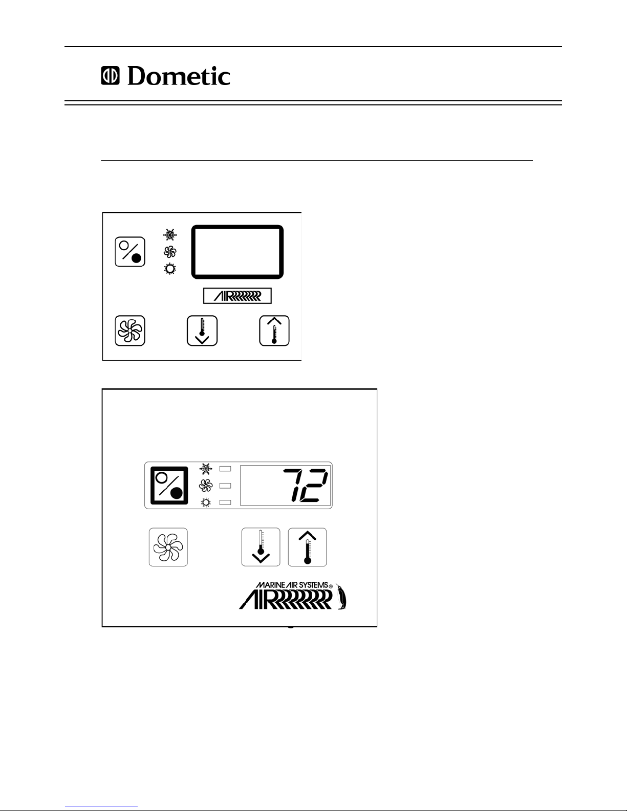
DESCRIPTION OF CONTROL
See Figure 1 and Table 1 on page 3 to identify all parts of the control.
POWER
Press the Power button once to engage the system. The display is blank when the system is off and indicates current room
temperature when the system is on.
SET POINT
Press the Up or Down button to set the desired room temperature. To view the set point, momentarily press and release the Up
or Down button.
FAN
Fan-speed operation is automatic, allowing fan speed to decrease as set-point temperature is approached in the Cool Mode.
The fan operates at low speed when set point is satisfied.
Normally the automatic fan speed operation is reversed in the Heating Mode, however, you can program the fan to operate the
same as in the Cooling Mode.
Press the Fan button to select manual fan speeds if you want to override automatic operation. You can program the fan to run
only during a cool or heat cycle, otherwise the fan runs constantly.
MEMORY
The AH-Passport I/O has nonvolatile memory requiring no batteries or backup power. When power is lost, the operating
parameters are retained indefinitely. When power is restored, the control resumes operating as last programmed.
2 L-2232 ENGLISH
AH-Passport I/O Control Operations Manual Description of Control
123
4
5
67
8
9
4
123
7 6
5
8
9
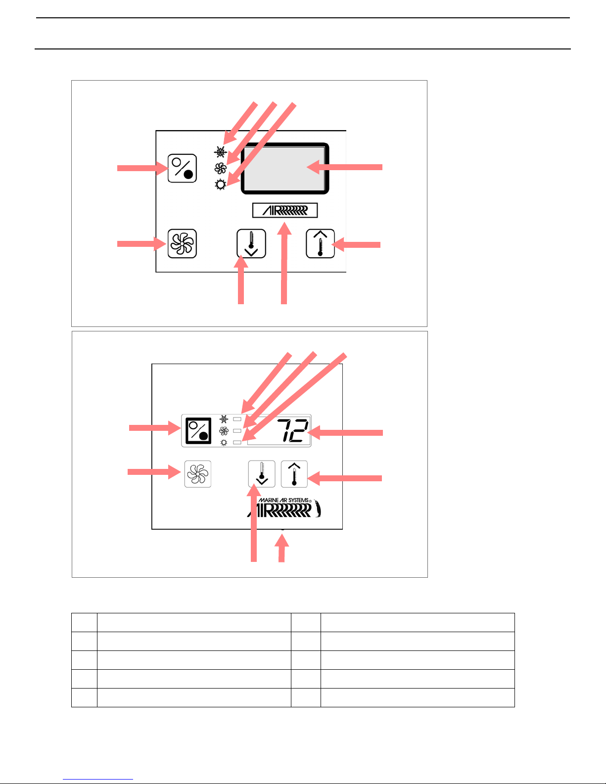
Compact model
Legacy model
Figure 1: AH-Passport I/O Display Panel and Indicators
Table 1: AH-Passport I/O Display - Diagram Legend
1
Cool Mode indicator
2
Fan indicator
6
7
Temperature sensor
Down button - Lower temperature set point
3
Heat Mode indicator
4
Digital display
5
Up button - Raise temperature set point
L-2232 ENGLISH 3
8
9
Fan button
Power button

Important Programming Notes To Installer and End User AH-Passport I/O Control Operations Manual
IMPORTANT PROGRAMMING NOTES TO INSTALLER AND END USER
1. If your air handler has a Shaded-Pole (SP) fan motor instead of a Split-Capacitor (SC) High-Velocity (HV) fan motor,
you MUST program “SP” into parameter P-16 before operating the equipment. The SP units are recognizable by an
overhanging blower motor. (The SC motor of an HV unit is inside the blower, and the unit has “VTD” or “HV” in the
model number.) Only reprogram this parameter if you do NOT have an HV blower.
2. Standard air handlers come equipped with chilled-water bypass valves. However, for “no-valve” air handlers, the fan
must be set to “cycle on demand” via programming parameter P-14. Verify that the installed air handlers have bypass
valves; if not, change parameter P-14 to “CYC” for cycle-on-demand fan operation
3. When powering on the control, press and immediately release the Power button so you do not unintentionally enter
Program Mode. You will enter Program Mode if the Power button is pressed and held for more than 5 seconds. If you
enter Program Mode unintentionally, any subsequent presses of the Up or Down buttons will change the P-1
parameter setting since it is the first parameter shown after entering this mode. This will change the operating mode to
Cool Only, Heat Only, or Auto matic, which could result in improper system operation. Always use care when in
Program Mode. For further information, refer to “Using Program Mode” on page 7.
NORMAL HEATING OR COOLING CYCLE
In Automatic Mode, heating and cooling are supplied as required. Based on the set point, Automatic operation maintains a 2°F
(1.1°C) temperature variation. If a 4° F (2.2° C) change in temperature occurs, the unit to shifts to the opposite mode. Once in
Heat Mode or Cool Mode, the control maintains a 2°F (1.1°C) differential.
If you program Cool Mode, only cooling is supplied. The cabin temperature is maintained within 2°F (1.1°C) of set point. If you
program Heat Mode, only heating is supplied. The cabin temperature is maintained within 2°F (1.1°C) of set point. When the
heating or cooling set point is satisfied, the hydronic water valve closes and the fan returns to low speed. The fan speed
remains constant if Manual Fan Speed is selected.
For more programming information on this feature, see “P-1: Operating Mode” on page 27.
When cooling or heating is required, the water valve will not open unless the water temperature is adequate. You can view
the water temperature by simultaneously pressing the Up and Power buttons. The fan remains in low speed until the adequate
water temperature is available. Heat will be supplied when no heating water is available only if the Optional Electric Heater has
been installed and programmed.
Adequate cooling or heating water temperature is defined by programmable parameter P-19. Its factory default is set at a
15° F (8.3° C) differential from the ambient air temperature. While in Heating or Cooling Mode, the control maintains a 2° F (1.1°
C) temperature variation. A 4° F (2.2° C) swing is required to cause the unit to shift to the opposite mode. Once in a new mode,
Heating or Cooling, the control maintains a 2° F (1.1° C) differential.
INSTALLING THE DISPLAY PANEL
CHOOSING THE LOCATION
Before mounting the control panel, consider the location. The display panel’s built-in air sensor provides excellent room-air
temperature sensing when properly located and installed. For air-sensor location see item 6 in Figure 1, page 3.
Mount the display panel on an inside wall, slightly higher than mid-height of the cabin, in a location with freely circulating air
where it can best sense average temperature. Its distance from the air handler control box must be within the 15’ (4.5m) length
of the display cable (custom lengths available).
Do not mount the display in direct sunlight, near any heat-producing appliances or in a bulkhead where temperatures radiating
from behind the panel may affect performance. Do not mount the display in the supply-air stream. Do not mount the display
above or below a supply-air or return-air grille. Do not mount the display behind a door, in a corner, under a stairwell or any
place where there is no freely circulating air.
If you can not mount the display in a suitable location for accurately sensing room temperature, install the optional remote air
sensor.
MOUNTING THE DISPLAY
1. Make the cut-out for the display panel.
• For Compact - Cut-out size is 2.4" (61mm) wide by 1.8" (46mm) high .
• For legacy model - Cut-out size is 3.375" (86mm) wide by 2.875" (73mm) high.
2. Plug one end of the display cable (8-pin connector) into the upper-right socket on the circuit board in the electric box
and the other end into the back of the display panel.
4 L-2232 ENGLISH
 Loading...