

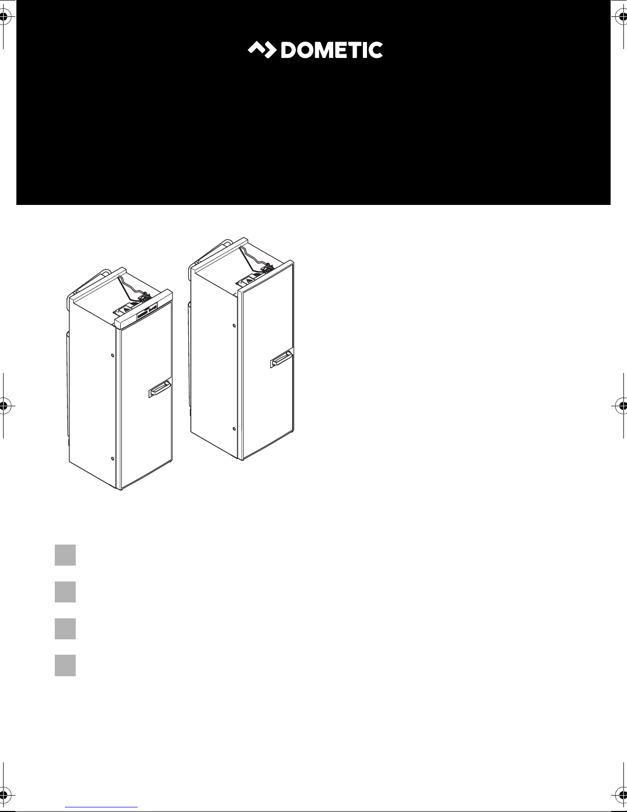
Dometic RML933 Series, 9 SERIES, RML943 Series, RML9335, RML9431 Installation Manual
...
RML943x
RML933x
ENDEFR
NL
REFRIGERATION
9 SERIES
RML9330, RML9331, RML9335
RML9430, RML9431, RML9435
Absorber refrigerator
Installation Manual. . . . . . . . . . . . . . . . . . . . 14
Absorber-Kühlschrank
Montageanleitung. . . . . . . . . . . . . . . . . . . . 31
Réfrigérateur à absorption
Instructions de montage . . . . . . . . . . . . . . .49
Absorptiekoelkast
Montagehandleiding . . . . . . . . . . . . . . . . .69
RML9xxx
1
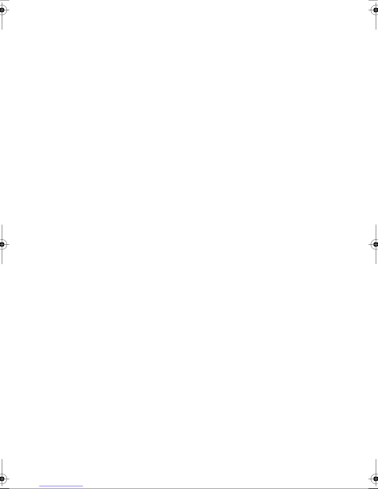
586,5 mm420 mm
1293 mm
RML 9330, RML 9331, RML 9335
553 mm
468 mm
1293 mm
RML 9430, RML 9431, RML 9435
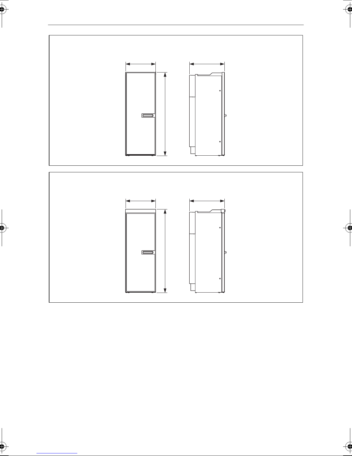
2
3
RML9xxx
2
3
4
1
3
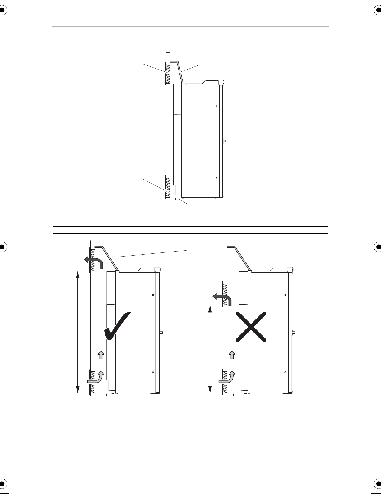
≥ 1050
< 1050
1
4
4
RML9xxx
15 – 25 mm
> 25 mm
> 25 mm
5
≥ 1350
15 – 25 mm
1
6
5
RML9xxx
≥ 300
1 2
7
918
1
2
3
4
1
3
2
4
LS 230 LS 330
0
6
RML9xxx
a
b
LS 230
LS 330
1.
2.
3.
c
d
LS 230
LS 330
LS 230
LS 330
1
2
7
1.
e
f
1
2
3
4
g
h
1.
2.
3.
RML 9430
i
1.
3.
2.
RML 9431, RML 9435
j
RML9xxx
2.
1
2
8
RML9xxx
k
l
n2xm
p
o
q
2.
1.
2x
9
RML9xxx
r
s
SW 17
SW 14
t
AB
1270,5
402
189
≤ 2,5
49583,5
49583,5
402
1216
1270,5
189
≤ 2,5
448
46
194,5
≤ 2,5
A B
1.
2.
3.
10
RML9xxx
u
rt
+
1
2
15
br
87
85 86
30
14
ws
br
ws
ws
_
3
4
5
_
sw
bl
+
gn
ws
br
ge
ws
+
br
6
br
78
ws
rt
sw
br
12
bl
sw
6a
6b
4a
4b
ws
2a
br
2b
10
rt
11
5b
5a
3b
3a
1b
1a
ge
gn
br
br
bl
bl
br br
bl bl
10
ge/gn
ge
E
L
F
G
9
N
10
ge/gn
V85
br
br
13
ge/gn
bl br ge gn rt sw ws
EN Blue Brown Yellow Green Red Black White
DE Blau Braun Gelb Grün Rot Schwarz Weiß
FR Bleu Marron Jaune Vert Rouge Noir Blanc
NL Blauw Bruin Geel Groen Rood Zwart Wit
11
RML9xxx
v
1
12
2
NL
L
N
15
3
LLNN
IN OUT
AC
TO GV 12VDCOUT
TO FC
TOP
4
14
rt
ABS
11
(+)
HE OUT 12 VDC HE IN
(-)
brbrbrws
(-)
(+)
6
13
(-)
rt
S+D+(+)
9
sw
A
10
BCDE FG
8
br rt sw ws
EN Brown Red Black White
DE Braun Rot Schwarz Weiß
FR Marron Rouge Noir Blanc
NL Bruin Rood Zwart Wit
7
5
sw
rt
12
RML9xxx
RML 93…
RML 94…
w
13
EN
Explanation of symbols RML9xxx
Please read this instruction manual carefully before installation and first
use, and store it in a safe place. If you pass on the product to another
person, hand over this instruction manual along with it.
NOTE
You can find details on the operation in the manual.
I
Table of contents
1 Explanation of symbols . . . . . . . . . . . . . . . . . . . . . . . . . . . . . . . . . . . . . . . . . .14
2 Safety instructions . . . . . . . . . . . . . . . . . . . . . . . . . . . . . . . . . . . . . . . . . . . . . .15
3 Scope of delivery . . . . . . . . . . . . . . . . . . . . . . . . . . . . . . . . . . . . . . . . . . . . . .16
4 Accessories . . . . . . . . . . . . . . . . . . . . . . . . . . . . . . . . . . . . . . . . . . . . . . . . . . .17
5 Intended use . . . . . . . . . . . . . . . . . . . . . . . . . . . . . . . . . . . . . . . . . . . . . . . . . .17
6 Installing the refrigerator. . . . . . . . . . . . . . . . . . . . . . . . . . . . . . . . . . . . . . . . .17
7 Connecting the refrigerator . . . . . . . . . . . . . . . . . . . . . . . . . . . . . . . . . . . . . 24
8 Technical data . . . . . . . . . . . . . . . . . . . . . . . . . . . . . . . . . . . . . . . . . . . . . . . . 29
1 Explanation of symbols
WARNING!
!
Safety instruction: Failure to observe this instruction can cause fatal or
serious injury.
CAUTION!
Safety instruction: Failure to observe this instruction can lead to injury.
!
NOTICE!
A
Failure to observe this instruction can cause material damage and impair
the function of the product.
NOTE
Supplementary information for operating the product.
I
14
EN
RML9xxx Safety instructions
2 Safety instructions
The manufacturer accepts no liability for damage in the following cases:
• Faulty assembly or connection
• Damage to the product resulting from mechanical influences and excess voltage
• Alterations to the product without express permission from the manufacturer
• Use for purposes other than those described in the operating manual
WARNING!
!
• Never open the absorber unit. It is under high pressure and can cause
injury if it is opened.
• Ensure clean and residue-free handling if silicon sealant or similar is
used. There is a risk of fire if silicone filaments come into contact with
hot parts or naked flames.
• Do not operate the refrigerator if it is visibly damaged.
• If the AC power cable for this refrigerator is damaged, it must be
replaced by the manufacturer, customer service or a similarly qualified
person in order to prevent safety hazards.
• Never use a naked flame to check the refrigerator for leaks.
• This refrigerator may only be repaired by qualified personnel. Inade-
quate repairs may cause serious hazards.
• Only use propane or butane gas (not natural gas).
• Only operate the refrigerator at the pressure shown on the type
plate. Only use pressure controllers with a fixed setting which comply
with the national regulations (in Europe EN 12864).
• Dismantle all refrigerator doors for the disposal of the old refrigerator
and leave the shelves in the refrigerator to prevent accidental enclosure and suffocation.
CAUTION!
• Danger of crushing! Do not put your fingers into the hinge.
!
• Before starting the device, ensure that the power supply line and the
plug are dry.
NOTICE!
A
• Only hold the refrigerator at the body of the refrigerator during transport. Never hold the refrigerator at the absorber unit, the cooling fins,
the gas pipes, the door or the control panel.
15

EN
Scope of delivery RML9xxx
• Make sure that the refrigerator circuit is not damaged during transportation. The refrigerant in the refrigerator circuit is highly flammable.
In the event of any damage to the refrigerator circuit (smell of ammonia):
– Switch off the refrigerator if applicable.
– Avoid naked flames and sparks.
– Air the room well.
• Do not install the refrigerator near naked flames or other heat sources
(heaters, direct sunlight, gas ovens etc.).
• Danger of overheating!
Always ensure sufficient ventilation so that the heat generated during
operation can dissipate. Make sure that the refrigerator is sufficiently
far away from walls and other objects so that the air can circulate.
• Check that the voltage specification on the type plate is the same as
that of the power supply.
• Do not open the refrigerant circuit under any circumstances.
• Only use the AC connection cable supplied to connect the refrigera-
tor to the AC mains.
• Only use cables with a suitable size.
• Never pull the plug out of the socket by the connection cable.
• The refrigerator may not be exposed to rain.
3Scope of delivery
• Refrigerator
• Ice-cube tray
• Operating manual
• Installation manual
16
EN
RML9xxx Accessories
4Accessories
Available as accessories (not included in the scope of delivery):
Description
Fan kit for boosting the cooling capacity at high ambient temperatures
Ventilation grille
Winter cover for the ventilation grille
Divider, bottle finger (RML9430/9431/9435 only)
Shelf with safety edges (RML9430/9431/9435 only)
Door shelf locking
Bottle holder for door shelf locking
Shelf locking
All the accessories are available from specialist dealers. If you have any questions,
please contact the dealer or your service partner directly.
5 Intended use
The RML9330, RML9331, RML9335, RML9430, RML9431 and RML9435 refrigerators are designed for installation in caravans or motorhomes. They are only suitable
for cooling and storing foodstuffs. The refrigerators are not intended for the proper
storage of medicine.
The refrigerators are designed to be operated on a DC power supply and an
AC socket and can be independently powered by liquid gas (propane or butane).
The refrigerators may not be run on natural gas or city gas.
6 Installing the refrigerator
6.1 Preparing the installation
When installing the refrigerator, note the following:
• To enable the refrigerant to circulate properly, the refrigerator may not exceed an
angle of 3°.
To do this, park the vehicle on a level surface and check to see if the ice-cube tray
is flat in the refrigerator.
17

EN
Installing the refrigerator RML9xxx
• The refrigerator must be installed so that it is easily accessible for service work,
easy to de-install and install and can be easily removed from the vehicle.
• The distance between the refrigerator and the rear wall must be min. 15 mm –
max. 25 mm (fig. 5, page 5).
• The refrigerator must be installed in a recess so that it stands firm when the vehicle
is in motion. Note the following dimensions here (H x W x D in mm):
– RML9330/9331/9335: 1293 x 420 x 586.5 (fig. 1, page 3)
– RML9430/9431/9435: 1293 x 468 x 553 (fig. 2, page 3)
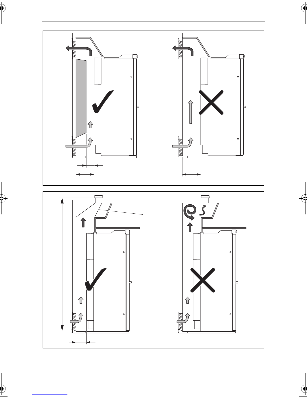
• The outer wall must be fitted with an air inlet vent (fig. 3 1, page 4) and an outlet
vent (fig. 3 2, page 4) with ventilation grilles so that the heat generated can be
easily released to the outside:
– Air inlet vent: Fit the ventilation grille as flush as possible to the floor of the
installation niche with a minimum cross-section of 500 cm
2
.
– Outlet vent: fit as far above the refrigerator as possible.
– The distance between the air inlet and outlet vents must be at least 1050 mm
(fig. 4, page 4).
• Fit a heat conduction plate (fig. 3 3, page 4) above the refrigerator so that the
heat does not accumulate in the vehicle.
• If the ventilation grille of the air inlet vent cannot be installed flush to the ground,
an additional inlet vent (fig. 3 4, page 4) must be provided in the floor for
releasing leaked gas.
• A distance of more than 25 mm between the refrigerator and rear wall leads to
poor performance and increases the power consumption of the refrigerator.
Reduce the space behind the refrigerator to create adequate air inlet and outlet
ventilation (fig. 5, page 5). Use a ventilation plate, for example, to do this.
• If the minimum distance between the air inlet and outlet vents cannot be met, a
roof vent must be installed instead of the air outlet vent.
– The roof vent should be installed directly above the back of the refrigerator as
far as this is possible. Use an air duct (fig. 6 1, page 5) if you need to install
the roof vent offset, otherwise heat will accumulate there.
– The distance between the air inlet vent and the roof vent must be at least
1350 mm (fig. 6, page 5).
– If a roof air conditioner is provided, the distance between the roof vent
(fig. 7 1, page 6) and the air outlet of the roof air conditioner (fig. 7 2,
page 6) must be at least 300 mm.
• The refrigerator must not be installed at the side of the air inlet and outlet vents as
this leads to poor performance and increases the power consumption of the
refrigerator.
• The air inlet and outlet vents must not be covered by vehicle parts (such as an
open door or by installing accessories such as bicycle racks) while operating.
18
EN
RML9xxx Installing the refrigerator
• Install the refrigerator so that it is protected from excessive heat, as this leads to
poor performance and increases the power consumption of the refrigerator.
• The electrical installation must comply with national and local regulations.
European standards: EN 60335-1, EN 60335-2-24, EN 1648-1 and EN 1648-2.
• The gas installation must comply with national and local regulations.
European standard: EN 1949.
• The refrigerator must be installed in a draught-proof location in accordance with
EN 1949, see chapter “Installing the refrigerator in a draught-proof location” on
page 19.
6.2 Installing the refrigerator in a draught-proof location
Gas-powered refrigerators in caravans or motorhomes must be installed in a
draught-free location according to EN 1949. This means that the combustion air is
not extracted from the interior and the exhaust fumes are prevented from directly
entering the living space.
A suitable seal must be fitted between the rear panel of the refrigerator and the
interior of the vehicle.
WARNING! Fire hazard!
!
The manufacturer recommends using a flexible seal to ease removal and installation
for maintenance purposes.
➤ Attach the sealing lips (fig. 8 1, page 6) to a stop rail behind the refrigerator, for
example, by using an adhesive.
➤ When installing, push the refrigerator against the stop rails with the sealing lips.
This then seals the space behind the refrigerator to the interior of the vehicle.
Do not use flammable materials such as silicone sealants, foam or similar
for the draught-proof installation.
19
EN
Installing the refrigerator RML9xxx
6.3 Making air inlet and outlet vents
NOTE
I
➤ Make an air inlet vent and an air outlet vent in the outer wall with the size of
410 mm x 249 mm. When doing so, observe the information, see chapter “Preparing the installation” on page 17.
If the ventilation grille of the air inlet vent cannot be installed flush with the floor of the
niche, you need to install an inlet vent in the floor:
➤ Make an air inlet vent in the floor (fig. 3 4, page 4) behind the refrigerator near
the gas burner.
At high ambient temperatures, the refrigerator can only provide its
maximum cooling capacity if the optimum ventilation has been
provided.
➤ Shield the end of the opening with a deflector to prevent sludge or dirt from get-
ting inside while driving (fig. 9, page 6).
If you have to use a roof vent instead of the air outlet vent:
➤ Cut out a section in the roof. Refer to the roof vent instruction manual for the
required dimensions. When doing so, observe the information, see chapter “Preparing the installation” on page 17.
20
EN
RML9xxx Installing the refrigerator
6.4 Installing the ventilation grille
No. in
fig. 0, page 6
1 Installation frame
2 Ventilation grille
3 Winter cover
4Slider
Description
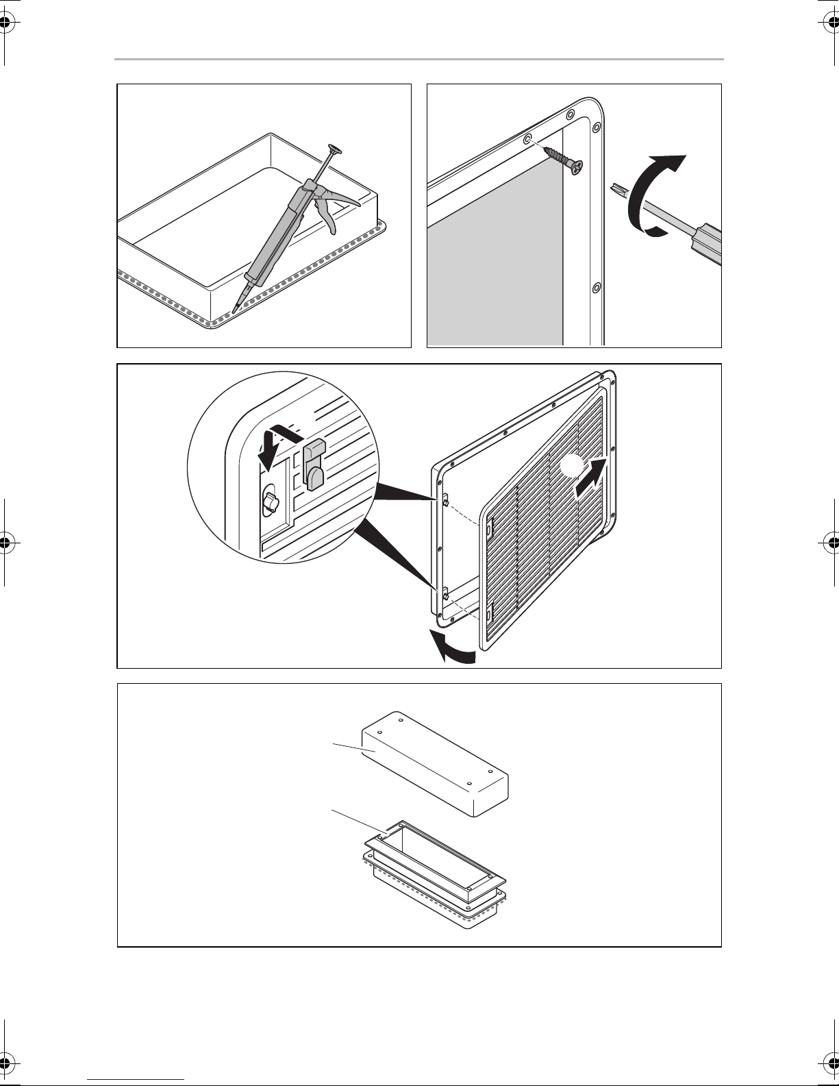
➤ Ensure the installation frame is water resistant (fig. a, page 7).
➤ Insert the installation frame and screw it down tightly (fig. b, page 7).
➤ Fit the ventilation grille (fig. c, page 7).
➤ Insert the slider and lock the ventilation grille with it (fig. c, page 7).
6.5 Install the roof vent
No. in
fig. d, page 7
Description
1 Installation frame
2 Hood
➤ Ensure the installation frame is water resistant (fig. e, page 8).
➤ Insert the installation frame and screw it down tightly (fig. e, page 8).
➤ Insert the hood and screw it down tightly (fig. f, page 8).
21
EN
Installing the refrigerator RML9xxx
6.6 Install the flue duct
NOTE
I
The flue duct is installed at the factory. Follow these steps when you have removed
the flue duct and want to reinstall it (fig. g, page 8):
➤ Place the T-piece (1) on the adaptor (2) and the flue pipe (3).
➤ Direct the T-piece at an angle of 45° towards the rear wall.
➤ Attach the T-piece, adaptor and flue pipe with a screw (4).
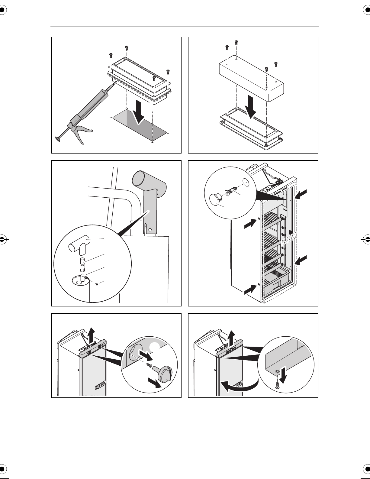
6.7 Securing the refrigerator
!
Do not install an additional flue stack, as this leads to poor performance
and increases the power consumption of the refrigerator.
CAUTION!
Only drill through the receptacles provided, otherwise foamed
components, including cables, can be damaged.
NOTE
I
Proceed as follows (fig. h, page 8):
➤ Move the refrigerator into its final location.
➤ Fasten the four screws (1) through the four plastic washers in the sides of the
refrigerator, and further into the wall.
➤ Put the caps (2) onto the screw heads.
Attach the side walls or the attached strips so that the screws are tight,
even when under increased loads (while driving).
22
EN
RML9xxx Installing the refrigerator
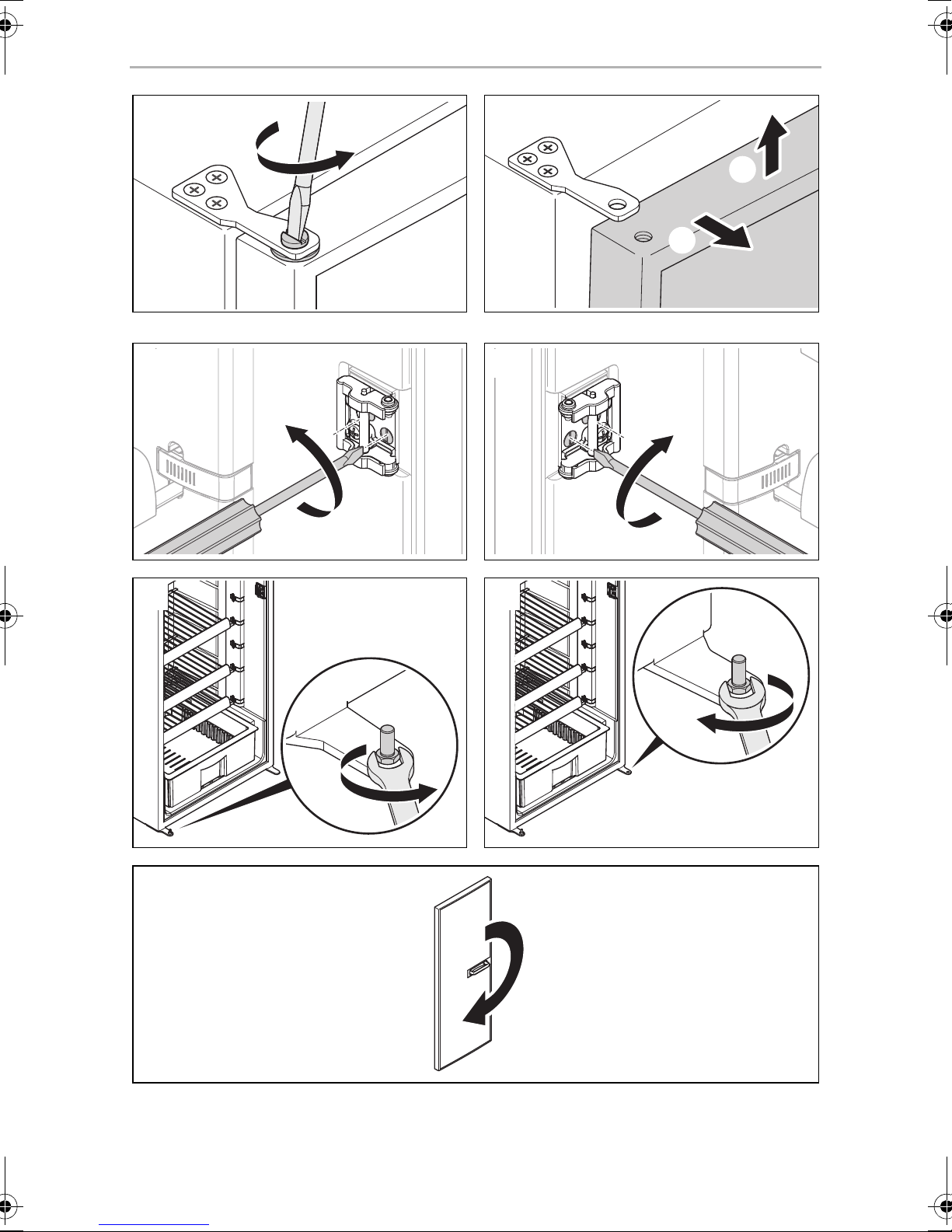
6.8 Reversing the door (RML9430/9431/9435 only)
➤ Remove the control panel.
– RML9430: Unscrew the dials carefully and loosen the screws (fig. i,
page 8).
– RML9431/9435: Open the refrigerator door and undo the screws
underneath the control panel (fig. j, page 8).
➤ Undo the hinge screw on the top door hinge and keep it in a safe place (fig. k,
page 9).
➤ Lift up the door and remove it (fig. l, page 9).
➤ Undo the two screws on the door lock and remove the door lock (fig. m,
page 9).
➤ Place the door lock on the other side again and tighten it with the two screws
(fig. n, page 9).
➤ Undo the hinge pin (fig. o, page 9) and position it on the other side (fig. p,
page 9).
➤ Turn the door by 180° (fig. q, page 9).
➤ Place the door on the hinge pin.
➤ Replace the control panel and screw it down tightly.
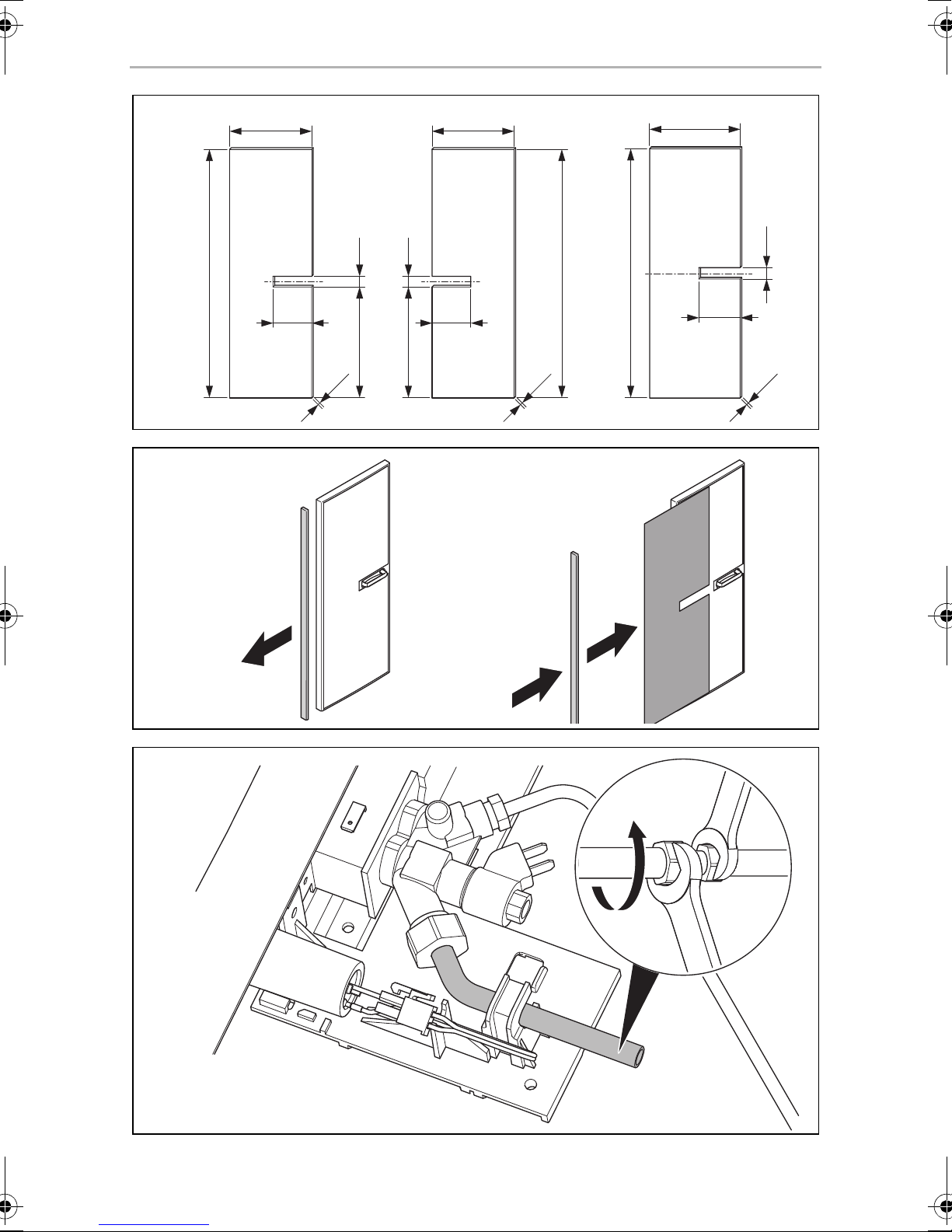
6.9 Put on the door panel
NOTICE! Beware of damage
A
The door panel has the following dimensions (fig. r, page 10):
• RML9330/9331/9335: A
• RML9430/9431/9435: B
Proceed as follows (fig. s, page 10):
➤ Remove the door trim carefully. It is only stuck on and held by small hooks (A).
Only ever lay the refrigerator on its side and never on its back. Otherwise
the unit may be damaged.
➤ Slide the new panel into the opening (B).
➤ Replace the door trim (B).
✓ The door trim is secure once it clicks into place.
23
EN
Connecting the refrigerator RML9xxx
If you have laid the refrigerator on its side to insert the panel:
➤ Wait a few minutes before you switch on the refrigerator.
7 Connecting the refrigerator
7.1 Connecting to the gas supply
NOTICE!
A
• This refrigerator may only be connected to the gas supply by a
specialist in accordance with the applicable guidelines and
standards.
• Only use cylinders of propane or butane gas (not natural gas or city
gas) with an approved pressure reduction valve and suitable head.
Compare the pressure information on the type plate with the
pressure information on the pressure regulator on the propane or
butane gas cylinder.
• Only operate the refrigerator at the pressure shown on the type
plate.
• Please note the pressures which are permitted in your country. Use a
DIN-DVGW-approved pressure regulator with a fixed setting:
– The following applies for Germany: DIN EN 12864
– The following applies for Europe: EN 732 and EN 1949
NOTE
I
It must be possible to shut off the refrigerator from the gas line separately by means
of a shut-off device. The shut-off device must be easily accessible.
➤ Connect the refrigerator securely by hand to the gas supply (fig. t, page 10).
The following applies for Europe: Use a cutting ring fitting in accordance with
EN 1949.
A hose connection is not permitted.
➤ Have a leak test and a flame test performed in accordance with EN 1949 by an
authorised specialist.
Ensure you are issued with a certificate of inspection.
The refrigerator is equipped for a connection pressure of 30 mbar. Use
a 50/30 mbar pressure regulator when connected to a 50 mbar system.
24
EN
RML9xxx Connecting the refrigerator
7.2 Connecting to 12 Vg and 230 Vw
NOTICE!
A
I
• The electrical installation and repairs may only be performed by a
specialist in accordance with the applicable regulations and
standards.
• According to EN 1648-1, the respective negative and positive cables
of the DC connections for heating and lighting may not be joined
with one another in a caravan. This can cause electrical interference
or damage to electrical components.
• The inverter may only be connected by a specialist.
NOTE
• The mains socket must be easily accessible so that you can unplug
the power cord if required, thereby disconnecting the refrigerator
from the power.
• The plug of the AC connection cable must not be cut off.
• The connection cables must be laid so that they do not come in
contact with hot parts of the unit/burner or with sharp edges.
• Changes to the internal electrical installation or the connection of
other electrical components (e.g. extra third party fans) to the
internal wiring of the refrigerator will void the E1/CE approval and
any claims from the guarantee and product liability.
25
EN
Connecting the refrigerator RML9xxx
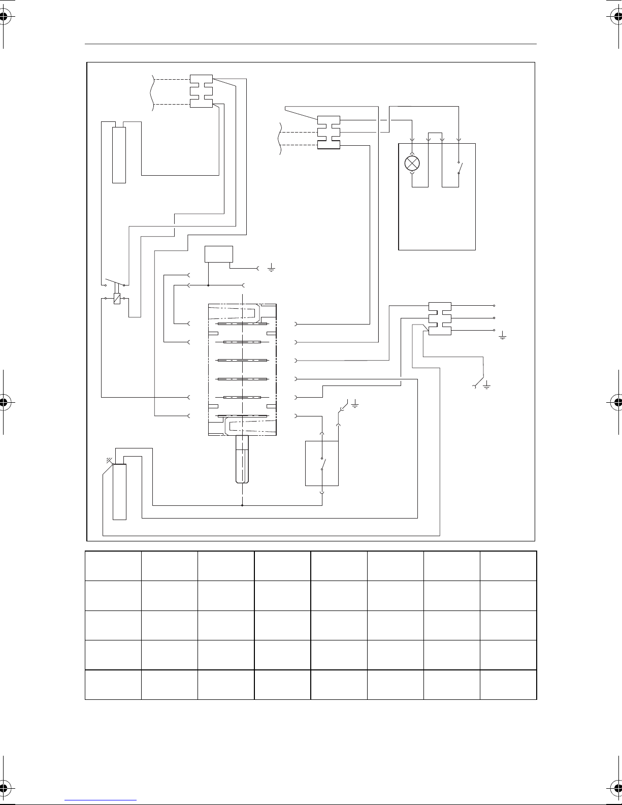
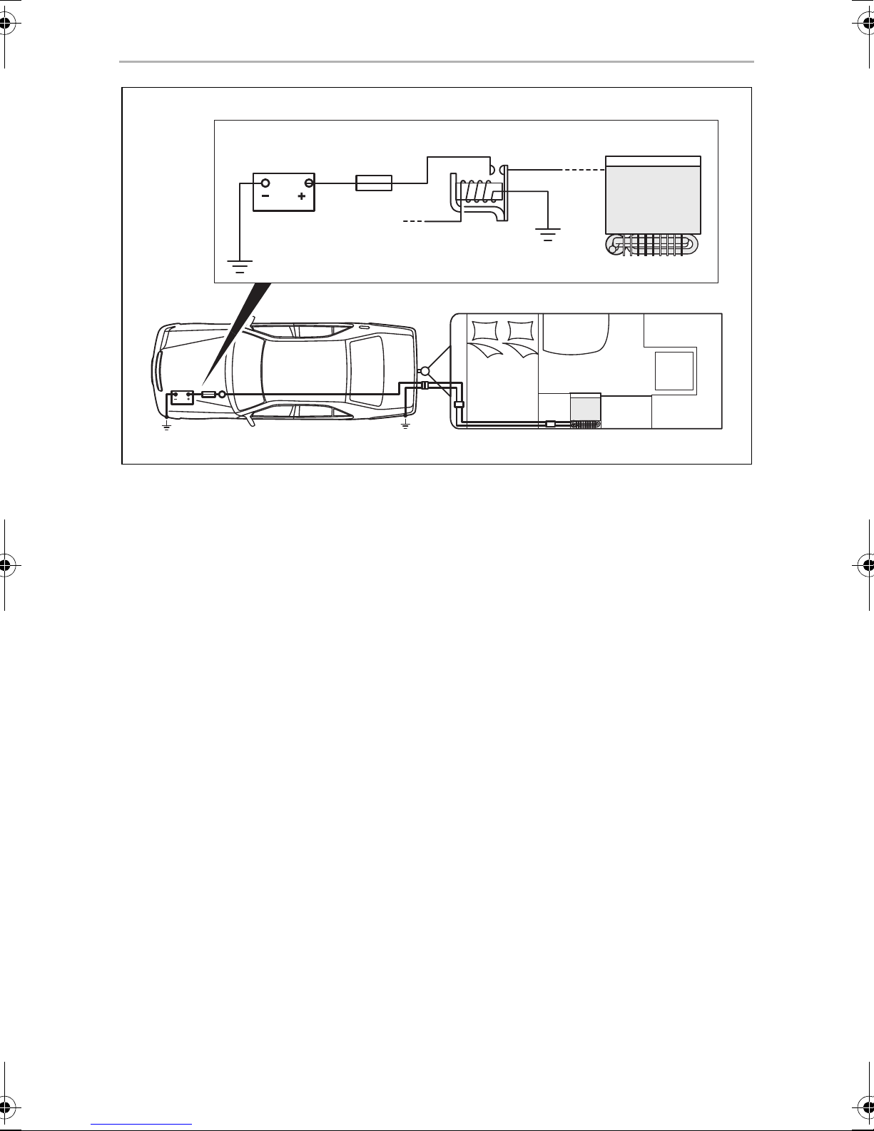
➤ Connect the RML9330/9430 refrigerators as follows (fig. u, page 11).
Item Description
1 Heating element positive terminal (+) DC power
2 Heating element earth terminal DC power
3 Heating cartridge terminal strip DC power
4 Lighting negative terminal (–)
5 Lighting positive terminal (+)
6 Lighting terminal strip DC power
7 LED lighting DC power
8 LED lighting switch
9 AC power connection cable
10 Earth housing (upper section)
11 Thermal power adapter
12 Galvanometer
13 Heating cartridge AC power
14 Relay 30 A
15 Heating cartridge DC power
26
EN
RML9xxx Connecting the refrigerator
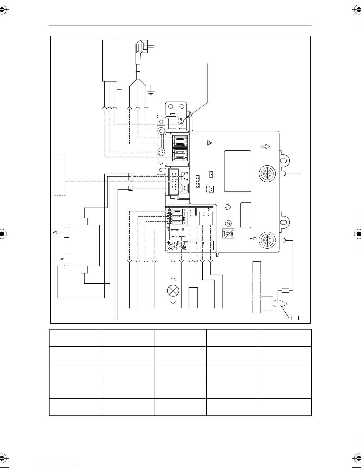
➤ Connect the RML9331/9335/9431/9435 refrigerators as follows (fig. v,
page 12):
Item Description
1 Heating cartridge AC power
2 AC power connection cable
3 Earth AC power
4 Ionisation
5 Ignition
6Burner
7 Heating cartridge DC power supply
8 Heating cartridge DC power
9 LED lighting
10 Electronics DC power supply
11 Gas inlet
12 Gas outlet
13 Gas valve
14 DC power outlet
15 Gas valve supply line
A Optional connections to DC power outlet
B Negative terminal (–) DC permanent supply for electronics
C Positive terminal (+) DC permanent supply for electronics
D Connection D+
E Connection S+
F Heating element positive terminal (+) DC power
G Heating element earth terminal DC power
AC power:
➤ Connect the refrigerator with the mains plug to an AC socket.
27
 Loading...