

Dometic 9500E Installation Instructions Manual
RECORD THIS INFORMATION FOR FUTURE
REFERENCE:
Model Number
Serial Number
Date Purchased
Retailer / Qualied Installer
TYPE
9500E
INSTALLATION
INSTRUCTIONS
(12 VDC) POWER
CASE / CASSETTE AWNING
MODEL
201(LL)(CC).003(#)
REVISION C
Form No. 3315066.000 12/16
(French 3315067.000_C)
©2016 Dometic Corporation
LaGrange, IN 46761
USA
SERVICE OFFICE
Dometic Corporation
1120 North Main Street
Elkhart, IN 46514
Read these instructions carefully. These
instructions MUST stay with this product.
CANADA
Dometic Corporation
46 Zatonski, Unit 3
Brantford, ON N3T 5L8
CANADA
SERVICE CENTER &
DEALER LOCATIONS
Please Visit:
www.eDometic.com

INTRODUCTION
This case awning (hereinafter referred to as “awning,” or “product”) is designed and intended for use on RVs with straight
sides. It is especially well suited for RVs with an over cab extension where there is not sufcient surface for a bottom mounting bracket. This product can be installed by one person with brief help from additional personnel. Use these instructions to
ensure correct installation and function of product.
Dometic Corporation reserves the right to modify appearances and specications without notice.
TABLE OF CONTENTS
INTRODUCTION .................................................................................................................................................................... 2
DOCUMENT SYMBOLS ........................................................................................................................................................2
IMPORTANT SAFETY INSTRUCTIONS ................................................................................................................................3
A. Recognize Safety Information ...................................................................................................................................3
B. Understand Signal Words ..........................................................................................................................................3
C. Supplemental Directives ............................................................................................................................................3
D. General Safety Messages .........................................................................................................................................3
GENERAL INFORMATION .....................................................................................................................................................3
A. Required Tools ...........................................................................................................................................................3
B. Required Hardware ...................................................................................................................................................3
C. Additional Hardware Quantity ....................................................................................................................................3
SPECIFICATIONS .................................................................................................................................................................. 4
A. Product Rating ........................................................................................................................................................... 4
B. Wiring Diagram .......................................................................................................................................................... 4
C. Door Clearance .........................................................................................................................................................4
D. Awning Dimensions ................................................................................................................................................... 4
INSTALLATION ......................................................................................................................................................................5
A. Determine Awning Location ....................................................................................................................................... 5
B. Install Mounting Bracket ............................................................................................................................................6
C. Install Wiring And Electrical Kits ................................................................................................................................7
D. Install Awning .............................................................................................................................................................8
E. Verify Motor And Remote Functionality .....................................................................................................................9
F. Verify Wind Sensor Functionality .............................................................................................................................10
ADJUSTMENTS (OPTIONAL) .............................................................................................................................................10
A. Adjust Fabric Slope (If Desired) ...............................................................................................................................10
B. Adjust Lateral Arm Assemblies (If Required) ........................................................................................................... 11
C. Adjust Lead Rail Alignment (If Required) .................................................................................................................13
VERIFY INSTALLATION.......................................................................................................................................................13
A. Test Operation .........................................................................................................................................................13
B. Secure Awning For Travel .......................................................................................................................................13
C. Keep Literature ........................................................................................................................................................13
DOCUMENT SYMBOLS
Indicates additional information that is NOT related
to physical injury.
Indicates step-by-step instructions.
2

IMPORTANT SAFETY INSTRUCTIONS
This manual has safety information and instructions to help
you eliminate or reduce the risk of accidents and injuries.
A. Recognize Safety Information
This is the safety alert symbol. It is used to
alert you to potential physical injury hazards.
Obey all safety messages that follow this
symbol to avoid possible injury or death.
B. Understand Signal Words
A signal word will identify safety messages and
property damage messages, and will indicate the
degree or level of hazard seriousness.
indicates a hazardous situation that,
if NOT avoided, could result in death or serious injury.
indicates a hazardous situation that,
if NOT avoided, could result in minor or moderate
injury.
is used to address practices NOT
related to physical injury.
C. Supplemental Directives
Read and follow all safety information and
instructions to avoid possible injury or death.
Read and understand these instructions before [installing / using / servicing / performing
maintenance on] this product.
Incorrect [installation / operation / servicing /
maintaining] of this product can lead to serious injury. Follow all instructions.
The installation MUST comply with all applicable local and national codes, including
the latest edition of the following standards:
U.S.A.
● ANSI/NFPA70, National Electrical Code
(NEC)
● ANSI/NFPA 1192, Recreational Vehicles
Code
CANADA
● CSA C22.1, Parts l & ll, Canadian Electri-
cal Code
● CSA Z240 RV Series, Recreational
Vehicles
D. General Safety Messages
Failure to obey the following warnings could result in death or serious injury:
● This product MUST be [installed / serviced] by a
qualied service technician.
● Do NOT modify this product in any way. Modica-
tion can be extremely hazardous.
GENERAL INFORMATION
A. Required Tools
● Electric Drill (optional)
● Torque Wrench
● Phillips Screwdriver / Bit
● 3 mm Hex Key / Driver / Bit
● 6 mm Hex Key / Driver / Bit
● 6 mm Hex Key Socket
● 10 mm Socket
B. Required Hardware
8′ - 13′ Models:
(1) Mounting Bracket
(12) M6 X 50 mm L Carriage Bolt
(12) M6 Split Lock Washer
(12) M6 Flat Washer
(12) M6 Locknut With Nylon Insert
(6) #8-18 X .38 Self Drilling Flat Head Screw
C. Additional Hardware Quantity
15′ - 16′ Models ONLY:
(4) M6 X 50 mm L Carriage Bolt
(4) M6 Split Lock Washer
(4) M6 Flat Washer
(4) M6 Locknut With Nylon Insert
(2) #8-18 X .38 Self Drilling Flat Head Screw
3
SPECIFICATIONS
A. Product Rating
If awning motor is operated for more than 3
minutes, it will be disabled temporarily to prevent overheating. If this occurs, the motor will
require a short rest period before it will operate again.
Voltage Current Speed
Power
Supply
Motor
Rating
12 Vdc 5 A N/A N/A
12 Vdc 3.7 A 15 RPM IP44
Duty Cycle
Intermittent
3 minutes
(2 cycles; extend and retract)
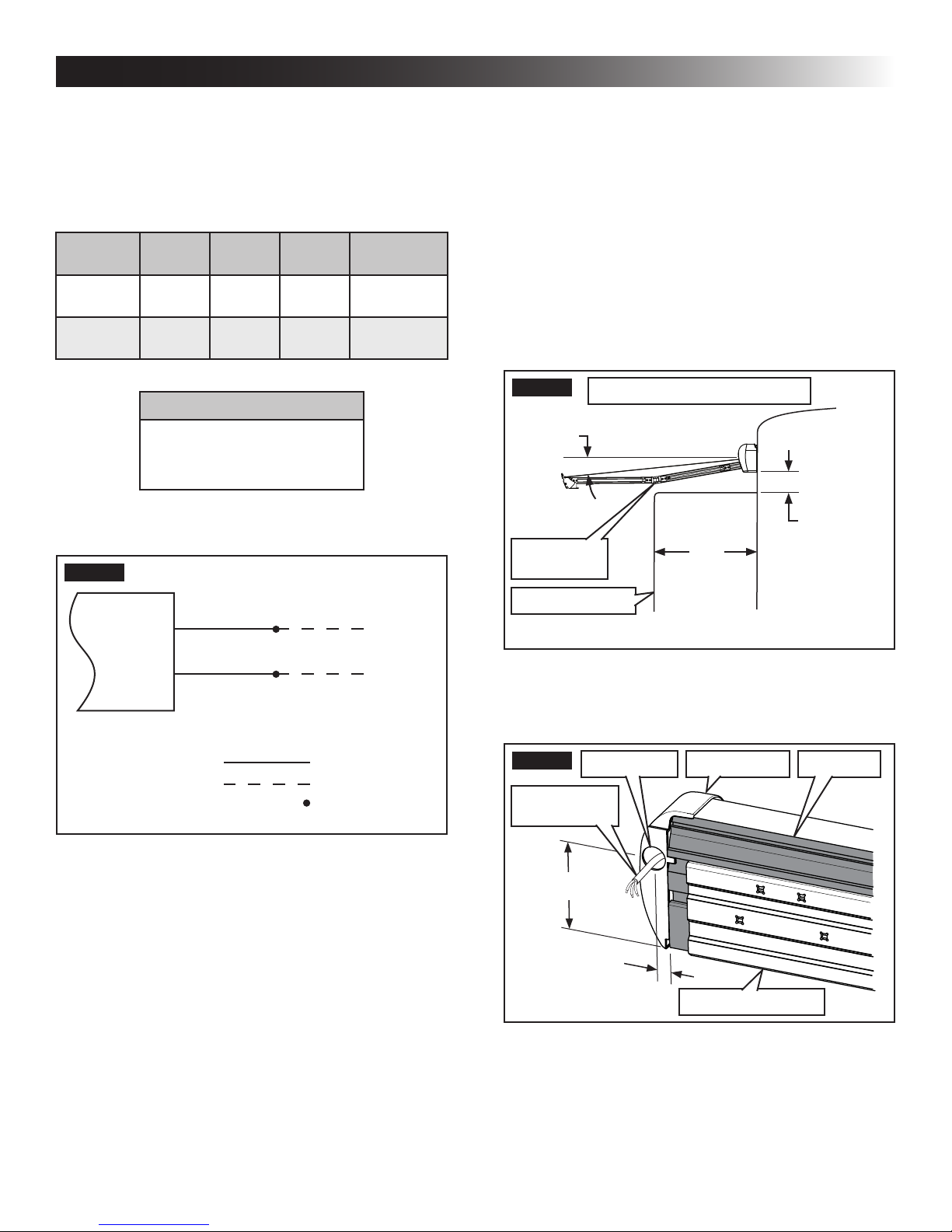
B. Wiring Diagram
FIG. 1
Protection
Index
C. Door Clearance
Allow for sufcient clearance be-
tween awning fabric and entry door to accommodate awning pitch (slope).
Awning is factory preset for a 5° fabric slope, but
it may be adjusted for a steeper slope (up to 15°).
See (FIG. 2).
For a 22″ entry door, the approximate minimum clearance is 2 1/2″ for 5° slope, and 6
1/2″ for 15° slope.
Make sure mounting surface on RV is at
and vertical. Any tilt in mounting surface will
tilt awning, and affect awning pitch (slope).
FIG. 2
Avoid
Interference
Typical Conguration Shown
5°
2 1/2″
22″
Red (or Brown)
Black (or Blue)
Positive (+)
Negative (-)
Factory Wire
Installer Supplied Wire
Installer Supplied
Wire Connector
RV Door (Open)
D. Awning Dimensions
1. Awning wiring hole location. See (FIG. 3).
FIG. 3
Wiring Hole Back Rail
Awning
Motor Wiring
4 1/4″
5/8″
RH End Cap
Mounting Bracket
4
 Loading...