

Dometic VERANDA ROOM, 935000.140, 935002.120, 935002.130, 935004.120 Installation & Operating Instructions Manual
...
RECORD THIS INFORMATION FOR FUTURE
REFERENCE:
Model Number
Serial Number
Date Purchased
Retailer / Qualied Installer
VERANDA ROOM
MODELS
935000.140 SIDE & DOOR ASSEMBLY - STANDARD
935000.150 SIDE & DOOR ASSEMBLY - TALL
935002.120 2' FRONT PANEL - STANDARD
935002.130 2' FRONT PANEL - TALL
935004.120 4' FRONT PANEL - STANDARD
935004.130 4' FRONT PANEL - TALL
935008.120 8' FRONT PANEL - STANDARD
935008.130 8' FRONT PANEL - TALL
INSTRUCTIONS
INSTALLATION & OPERATING
REVISION B
Form No. 3316484.000 4/17
English, French, Spanish
©2017 Dometic Corporation
LaGrange, IN 46761
USA
SERVICE OFFICE
Dometic Corporation
1120 North Main Street
Elkhart, IN 46514
Read these instructions carefully. These
instructions MUST stay with this product.
CANADA
Dometic Corporation
46 Zatonski, Unit 3
Brantford, ON N3T 5L8
CANADA
SERVICE CENTER &
DEALER LOCATIONS
Please Visit:
www.eDometic.com

INTRODUCTION
This Veranda Room (hereinafter referred to as "Veranda Room" or "Product") is designed and intended to fit
on most Dometic awnings and many other recreational vehicle (hereinafter referred to as "RV") awnings with a
3-1/2" roller tube. Use these instructions to ensure correct installation, function, and operation of product.
Dometic Corporation reserves the right to modify appearances and specications without notice.
TABLE OF CONTENTS
INTRODUCTION .................................................................................................................................................................... 2
DOCUMENT SYMBOLS ........................................................................................................................................................2
IMPORTANT SAFETY INSTRUCTIONS ................................................................................................................................2
A. Recognize Safety Information ...................................................................................................................................2
B. Understand Signal Words ..........................................................................................................................................2
C. Supplemental Directives ............................................................................................................................................2
D. General Safety Messages .........................................................................................................................................3
SPECIFICATIONS .................................................................................................................................................................. 3
A. Standard Height Veranda Room ................................................................................................................................3
B. Tall Height Veranda Room .........................................................................................................................................3
GENERAL INFORMATION .....................................................................................................................................................4
A. Tools & Supplies Required for Installation: ................................................................................................................4
INSTALLATION INSTRUCTIONS ..........................................................................................................................................6
OPERATING INSTRUCTIONS ............................................................................................................................................. 10
MAINTENANCE ................................................................................................................................................................... 11
A. Storage .................................................................................................................................................................... 11
B. Cleaning .................................................................................................................................................................. 11
DOCUMENT SYMBOLS
Indicates additional information that is NOT related
to physical injury.
IMPORTANT SAFETY INSTRUCTIONS
This manual has safety information and instructions to help
users eliminate or reduce the risk of accidents and injuries
A. Recognize Safety Information
This is the safety alert symbol. When you
see this symbol in this manual, be alert to
the potential for personal injury.
Follow recommended precautions and safe
operating instructions.
B. Understand Signal Words
A signal word, WARNING or CAUTION is used with
the safety-alert symbol. They give the level of risk
for potential injury.
indicates a potentially hazardous
situation which, if NOT avoided, could result in
death or serious injury.
C. Supplemental Directives
2
Indicates step-by-step instructions.
indicates a potentially hazardous
situation which, if NOT avoided, may result in minor
or moderate injury.
is used to address practices NOT
related to physical injury.
Read and follow all safety information and
instructions to avoid possible injury or death.
Read and understand these instructions
before [installing / using / servicing /
performing maintenance on] this product.
Incorrect [installation / operation / servicing
/ maintaining] of this product can lead to
serious injury. Follow all instructions.
The installation MUST comply with all
applicable local and national codes, including
the latest edition of the following standards.

IMPORTANT SAFETY INSTRUCTIONS
D. General Safety Messages
Failure to obey the following
warnings could result in death or serious injury:
This product MUST be serviced by
a qualied service technician.
SPECIFICATIONS
A. Standard Height Veranda Room
B. Tall Height Veranda Room
Do NOT modify this product in any
way. Modication can be extremely hazardous.
Ground to awning rail 93" to 110"
935000.140 Side & Door Asm.- Standard
Consists of:
(1) Zippered Door - Standard (34" x 93-1/2")*
(1) Left Side Panel - Standard
(1) Right Side Panel - Standard
(2) Rafter Poles
(2) Pole Holders
(2) Pole Holder Screws
(2) Vertical Poles
(2) Roller Tube Clamps
(11) Tent Stakes
(8) Poly Rope Clips
(13) Twist Fasteners
(2) Loop Fasteners Adhesive Backed 1x3"
(2) Hook Fasteners Adhesive Backed 1x3"
(1) Carry Bag
(1) Vehicle skirt (28" x 300")*
(2) Wheel Well Skirt (15" x 42")*
935002.120 2' Front Panel - Standard
Consists of:
(1) 2' Front Panel - Standard (24" x 93-1/2")*
(2) Tent Stakes
Ground to awning rail 111" to 120"
935000.150 Side & Door Asm.- Tall
Consists of:
(1) Zippered Door - Tall (34" x 103-1/2")*
(1) Left Side Panel - Tall
(1) Right Side Panel - Tall
(2) Rafter Poles
(2) Pole Holders
(2) Pole Holder Screws
(2) Vertical Poles
(2) Roller Tube Clamps
(11) Tent Stakes
(8) Poly Rope Clips
(13) Twist Fasteners
(2) Loop Fasteners Adhesive Backed 1x3"
(2) Hook Fasteners Adhesive Backed 1x3"
(1) Carry Bag
(1) Vehicle skirt (36" x 300")*
(2) Wheel Well Skirt (15" x 42")*
935002.130 2' Front Panel - Tall
Consists of:
(1) 2' Front Panel Tall (24" x 103-1/2")*
(2) Tent Stakes
935004.120 4' Front Panel - Standard
Consists of:
(1) 4' Front Panel - Standard (48" x 93-1/2")*
(2) Tent Stakes
935008.120 8' Front Panel - Standard
Consists of:
(1) 8' Front Panel - Standard (96" x 93-1/2")*
(3) Tent Stakes
* Designates Finished Dimensions
935004.130 4' Front Panel - Tall
Consists of:
(1) 4' Front Panel - Tall (48" x 103-1/2")*
(2) Tent Stakes
935008.130 8' Front Panel - Tall
Consists of:
(1) 8' Front Panel - Tall (96" x 103-1/2")*
(3) Tent Stakes
* Designates Finished Dimensions
3
SPECIFICATIONS
Table 1
VERANDA ROOM MODEL IDENTIFICATION
LETTER
935000.140 Side & Door Asm.- Std. AS
935000.150 Side & Door Asm. - Tall AT
935002.120 2' Front Panel - Std. BS
935002.130 2' Front Panel - Tall BT
935004.120 4' Front Panel - Std. CS
935004.130 4' Front Panel - Tall CT
935008.120 8' Front Panel - Std. DS
935008.130 8' Front Panel - Tall DT
Table 2
AWNING
SIZE
8' AS, CS AT, CT
9' AS, CS AT, CT
10' AS, BS, CS AT, BT, CT
11' AS, BS, CS AT, BT, CT
12' AS, DS AT, DT
13' AS, DS AT, DT
14' AS, BS, DS AT, BT, DT
15' AS, BS, DS AT, BT, DT
16' AS, CS, DS AT, CT, DT
17' AS, CS, DS AT, CT, DT
18' AS, BS, CS, DS AT, BT, CT, DT
19' AS, BS, CS, DS AT, BT, CT, DT
20' AS, DS, DS AT, DT, DT
21' AS, DS, DS AT, DT, DT
22' AS, BS, DS, DS AT, BT, DT, DT
23' AS, BS, DS, DS AT, BT, DT, DT
24' AS, CS, DS, DS AT, CT, DT, DT
25' AS, CS, DS, DS AT, CT, DT, DT
SUGGESTED PANEL QTY
Standard Tall
GENERAL INFORMATION
The Veranda Room is designed to t on most Dometic
awnings and many other RV awnings with a 3-1/2" roller
tube. The rafter poles enable the Veranda Room to be the
full length of the awning or (with the use of shorter front
panels) the Veranda Room can be used on a portion of
the awning. Separate front panels in shorter lengths are
available from your dealer. The Veranda Room includes
integrated privacy panels.
The Veranda Room front is designed so
there will be approximately 3 or more inches of awning
fabric overhanging the Veranda Room on each side. This
is provided to keep rain water from running off the edge of
the awning to the inside of the Veranda Room.
A. Tools & Supplies Required for
Installation:
● Tape Measure
● Electric Drill
● Step Ladder
● Marking Pen
● 1/8" Drill Bit
● Caulking Gun
● Silicone Sealant
● Round File
● Straight Edge
● Hammer (optional for tent stakes)
● String & Plumb Bob
● Phillips Screwdriver
● Scissors or Utility Knife
4

GENERAL INFORMATION
Read ALL of the following steps before beginning
installation.
During installation, care must be taken not to scrape
and damage the panels and skirts.
In order to correctly match the Veranda Room to
a particular awning-RV combination, the following
information must be known:
a. Center of arm to center of arm dimension,
less 4' side panel and door allowance. Divide
this gure by the 2', 4', and 8' panels and/or;
b. Optional Length divide by 2', 4', and 8'
panels.
c. The height of the awning rail (93" to 110"
standard height - 111" to 120" tall height).
See FIG. 1.
FIG. 1
The Veranda Room front panel length is a
combination of the door panel plus front panels.
The size of the front panels is based on customer
preference and the steps a or b previously listed.
For example:
19' Awning less 4' = 15
15 divided by 8=1 with 7 left over
7 divided by 4=1 with 3 left over
3 divided by 2=1
1 cannot be divided by any panel size.
The result is that a 19' awning needs (1 each) 8'
panel, (1 each) 4' panel and (1 each) 2' panel.
If the customer preferred 4' panels then (3 each) 4'
panels and (1 each) 2' panel are used. If 2' panels
are used the same awning requires 7.
See Table 2 on page 4 for Dometic suggested
awning length and panels required.
B
A
C
5
INSTALLATION INSTRUCTIONS
1. The rst step to ensure proper installation of a
Veranda Room is to park the RV on a at and
level surface.
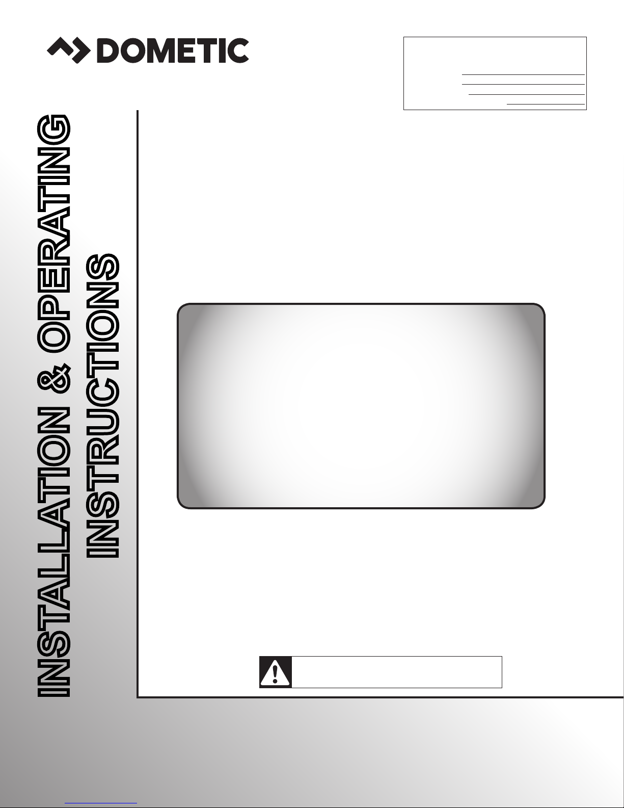
2. Open the awning (1) so that the slope of the
canopy approximates the angle of the side
panels (2). See FIG. 2. Make sure that the roller
tube (5) is level, and the roller tube is positioned
as shown in FIG. 3.
The Veranda Room may be enjoyed with
the awning support arms (3) (if applicable)
in the Patio Position as well as in the RV
Pivot Position.
FIG. 2
2
Adjust Awning Height To Match
The Slope Of The Side Panels
5
1
3
Awning Model May
Vary In Appearance
FIG. 4
9
8
Bottom Hole
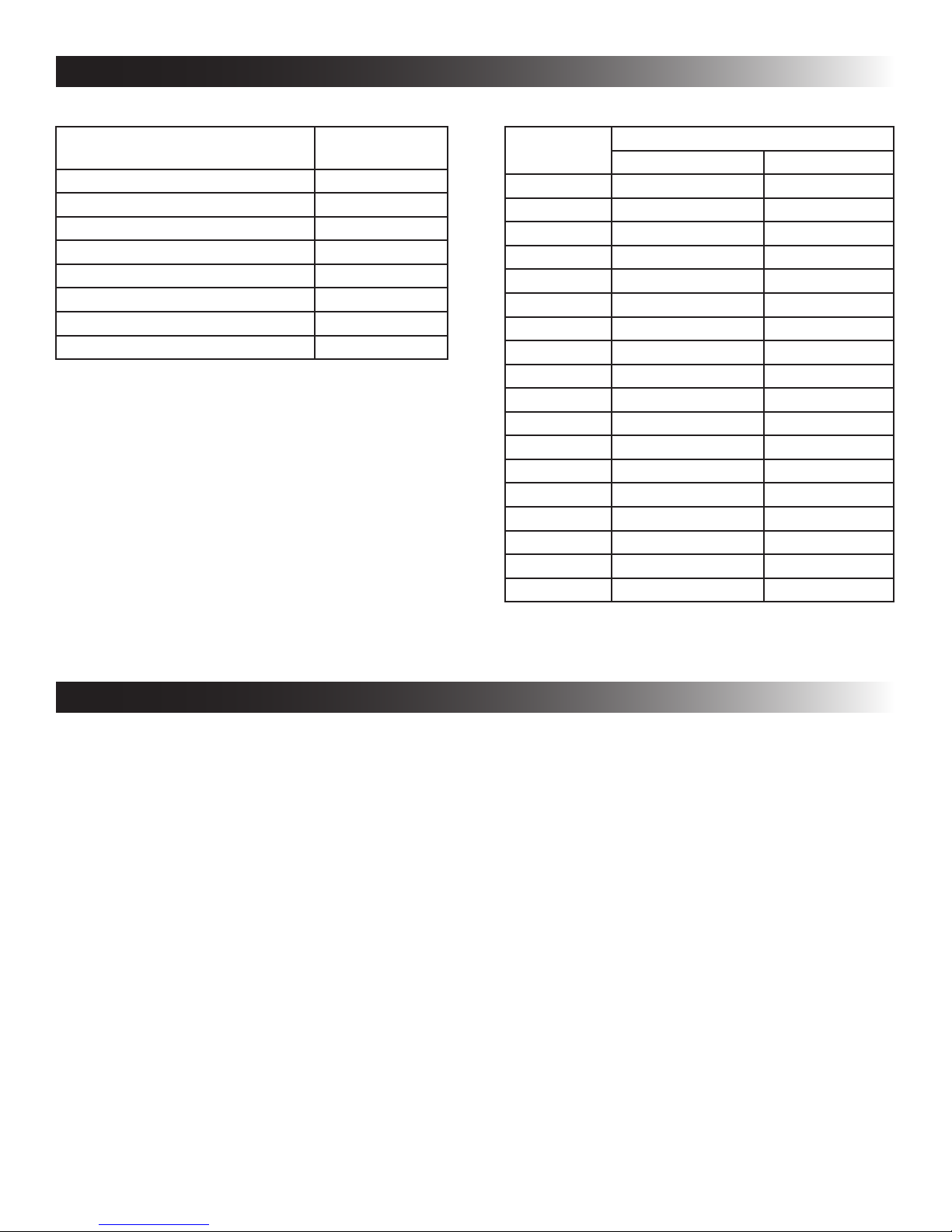
3. Check the accessory channel (6) in the end cap
(7) for burrs and sharp edges. Remove any burr
or sharp edges using a at or round le. See
FIG. 5.
FIG. 5
7
Left
Top Hole
10
1
FIG. 3
5
Valance
6
8
Approx. 72°
Edge Of Roller Tube Clamp
Approximately Vertical
6
1
4
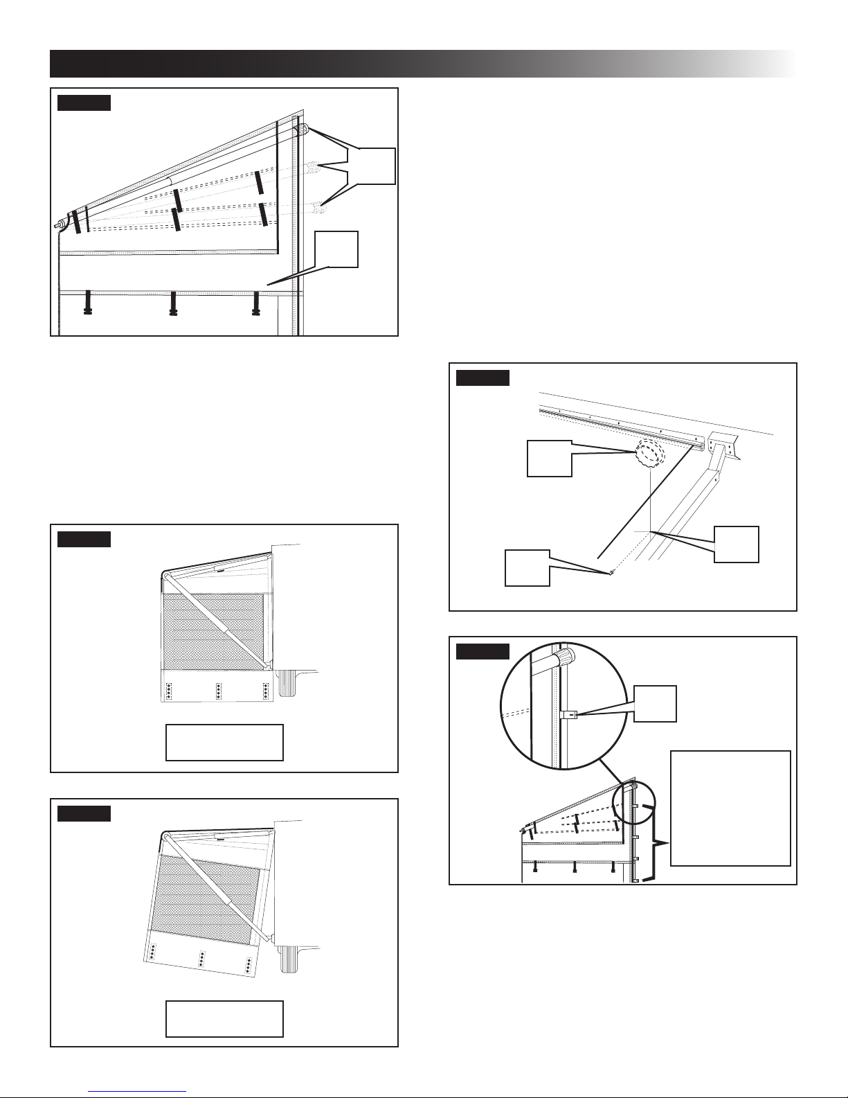
4. Install the rst of two roller tube clamps (8)
by aligning the roller tube insert (9) with the
accessory channel (6) on the left hand end cap
(7). Depress the spring button (10) to slide the
roller tube clamp (8) to the right end of the roller
tube (5). See FIG. 3 & FIG. 4.
Awning MUST be viewed from outside
(NOT underneath) to determine left hand
and right hand sides of the awning.
The Veranda Room front is
designed so there will be approximately 3 or
more inches of awning fabric overhanging the
Veranda Room on each side. This is provided to
keep rain water from running off the edge of the
awning to the inside of the Veranda Room.
Front
6
INSTALLATION INSTRUCTIONS
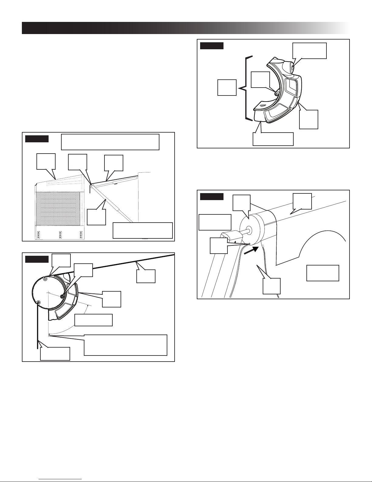
5. Release the adjustment clamp (35) on the
vertical pole (34) and extend the pole until it
reaches the roller tube clamp (8). Insert the
metal pin (36) on the end of the vertical pole (34)
into the bottom hole of the roller tube clamp (8).
FIG. 6
36
6. There is a 3/16" diameter poly rope sewn into
the top edge of the front panels (4). The front
panels (4) are to be hung from the roller tube
(5) by inserting the poly rope into the accessory
channel (6) in the left hand end cap (7) and
sliding it the entire length of the roller tube (5).
See FIG. 5. Make sure this accessory channel
(6) faces as shown in FIG. 3.
7. Zip the door and panels together to make the
front screen assembly. The door can be installed
on either end of the front or between panels.
8. While one person pulls on the leading edge of
the front assembly, a second person feeds and
guides the front panels (4) into the accessory
channel (6). The installer can spray the accessory
channel with a dry PTFE spray lubricant to make
this operation easier. See FIG. 5.
9. Install the second roller tube clamp (8) by aligning
the roller tube insert (9) with the accessory
channel (6) of the left hand end cap (7). Depress
the spring button (10) to slide up to the edge of
the front panels (4). See FIG. 3, FIG. 4, & FIG. 5.
10. Repeat the procedure in Step 5 for the vertical
pole (34) on the opposite end.
11. For the full width Veranda Room, place the front
panel as assembled so that it is centered in
relationship to the front of the awning.
A smaller Veranda Room used with a larger
awning may be located in a similar fashion
as long as the zipper at each end of the
front panel is used as a guide to locate the
roller tube clamp (8). See FIG. 3.
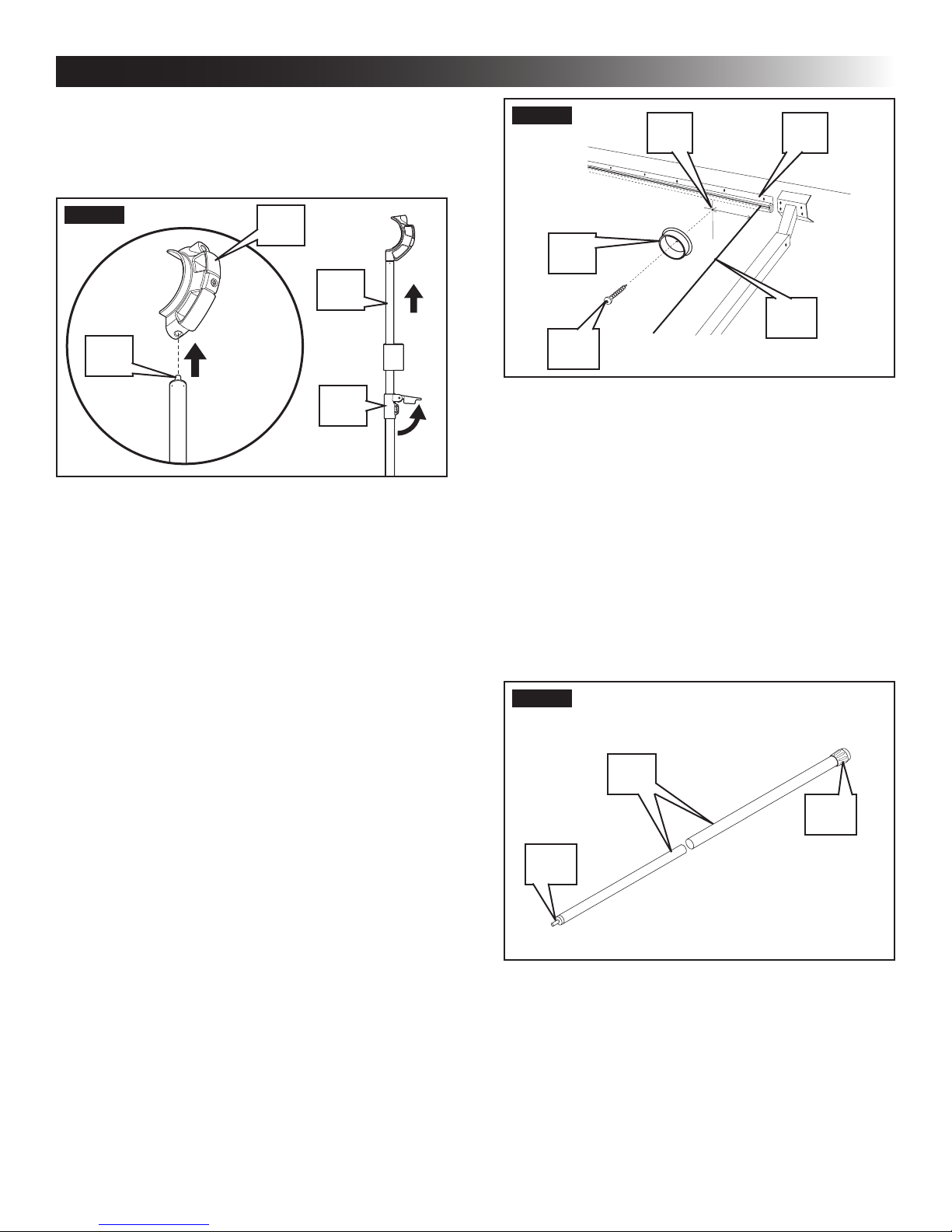
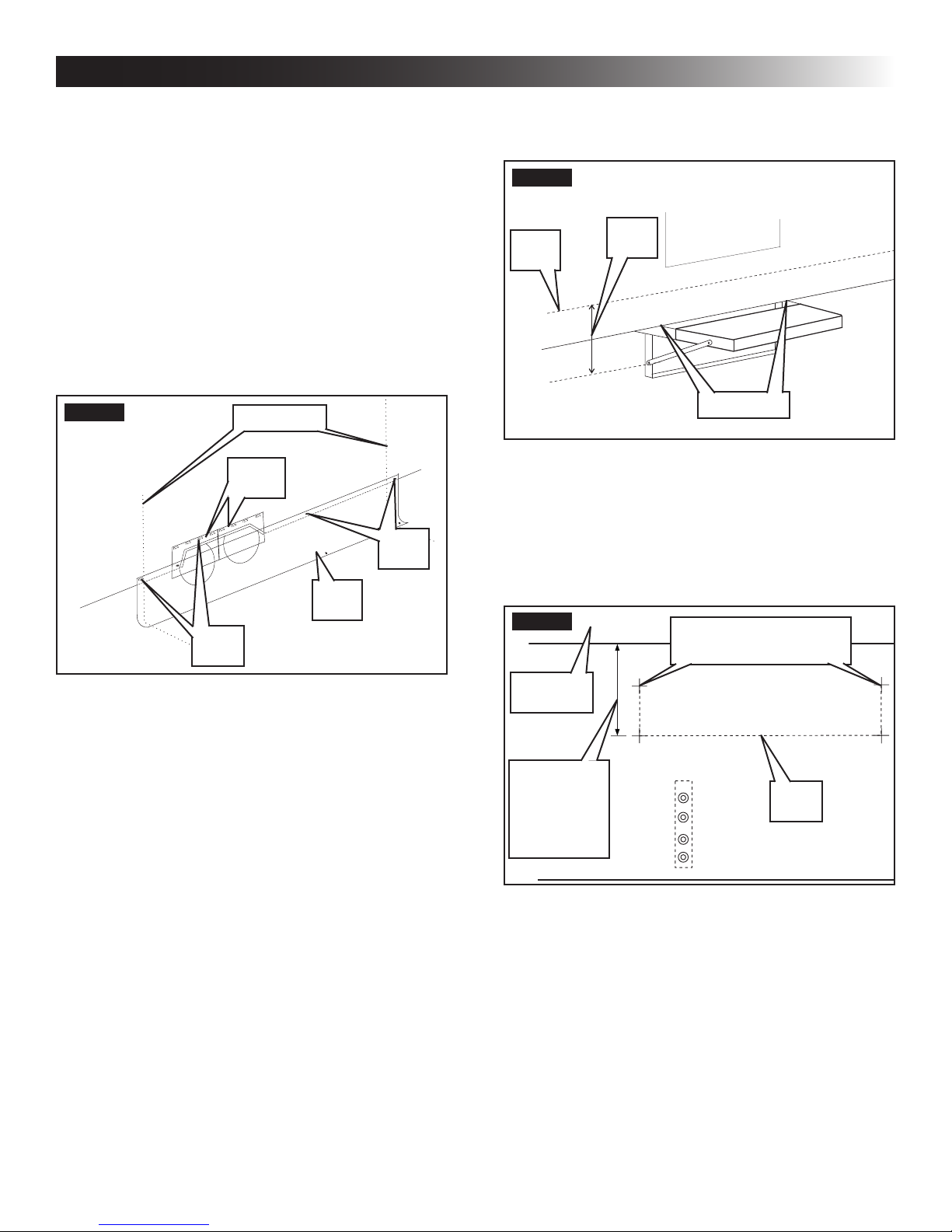
12. Measure the horizontal distance from the edge
of the awning fabric (11) to the center of the
top hole in the roller tube clamp. This is the
dimension for the location of the pole holder
(12). See FIG. 7.
8
34
35
FIG. 7
1314
12
11
15
13. Below the awning rail, measure and mark the
same dimension on the side of the RV below the
awning rail as measured in Step 12. Place the
pole holder (12) directly below the awning rail
(13) on the line and mark its center point. Use a
1/8" drill bit to make a pilot hole (14). See FIG. 7.
14. Apply silicone sealant to the screw (15) threads
and secure the pole holder (12) to the side wall
of the RV. See FIG. 7. Repeat Step 12 through
Step 14 for the opposite side.
15. The rafter poles (16) are in two pieces for easy
storage when not in use. Assemble the rafter
by inserting the pole with the metal pin (17) into
the pole with the rubber tip (18). Make sure the
metal pin (17) is visible. See FIG. 8.
FIG. 8
16
18
17
16. Slide the rafter pole (19) assembly through one
of the three pockets on the top edge of the side
panels (20). The top pocket is for most vehicles
with the awning high enough to be sloped
down. The middle and lower pocket are used on
RVs that need the awning to be relatively at.
See FIG. 9.
When the awning is relatively at and the
screen room pole is in the lowest position,
roll-up the awning if rain is anticipated to
prevent damages.
7
INSTALLATION INSTRUCTIONS
FIG. 9
20
17. With the rafter pole (19) still in the side panel
(20), place the rubber tip (18) into the pole holder
(12) under the awning rail. Apply pressure on the
rafter pole toward the RV wall compressing the
spring and put the metal pin in the top hole of
the roller tube clamp (8). See FIG. 4, FIG. 7, &
FIG. 9. Repeat on the other end.
18. Make sure the height of the roller tube is adjusted
so that all panels hang straight and level. See
FIG. 10 & FIG. 11.
19
19. Slide three poly rope clips (21) onto the poly
rope sewn on the side panel. Position the top
poly rope clip about 4" directly below the pole
holder (12) and drill a 1/8" pilot hole (23) for the
installation of the twist fastener (24). Use a string
and plumb bob to place the remaining twist
fasteners (24) evenly spaced in a straight line
down the wall of the RV. See FIG. 12 & FIG. 13.
The side panel assembly comes with eight
poly rope clips (21) and twist fasteners
(24). Only three clips are required for each
side. The extra are spares and can be
used if necessary. If the side panel is over
a window or storage compartment door,
place the poly rope clips immediately
above and below.
FIG. 12
12
FIG. 10
FIG. 11
23
24
FIG. 13
21
Correct
Space Twist
Fasteners For
Poly Rope Clips
In A Straight
Line On The Wall
Of Coach
20. Apply silicone sealant to the back and threads of
the twist fasteners before screwing them to the
side wall.
21. Slide each poly rope clip to mate up with its twist
fastener and attach it to the side wall. Repeat on
the opposite side.
Incorrect
8
INSTALLATION INSTRUCTIONS
22. Make sure the RV entrance steps are in the
extended or down position.
If the RV is equipped with an
automatic entry step, make sure the automatic
operation is disabled. Make sure this step
remains in the “down” or “extended” position
while installing and using the product.
23. The vehicle skirting (25) is one piece of fabric
300" long. The skirt is to be cut to t the Veranda
Room on which it is installed. The twist fasteners
(26) for the skirt need to be screwed into a solid
structure that is 1 to 2" from the bottom of the
RV wall. The skirt must extend past the end
of the right and left side panels (27) 3 to 4".
See FIG. 14.
FIG. 14
28
27
29
26
25
25. Locate the step and determine the uppermost
part (30) of it by feeling. Mark the edges of the
step on each side (31). See FIG. 15.
FIG. 15
30
26. Measure down from the top edge of the skirt to
the lowest part of the step (32). Add 1/4" to this
measurement. Mark a line for the cut for the step
on the skirt fabric. See FIG. 15.
27. Draw three lines (33) for the step ap on the
skirt fabric and cut with scissors or a utility knife.
See FIG. 16.
FIG. 16
32
31
Marks For The Top And
Widest Part Of Step
24. Drill a 1/8" pilot hole for the twist fastener at the
right/left corner of the Veranda Room. Mark the
opposite end of the fabric to be trimmed 3 to 4"
past the end of the Veranda Room. Square and
cut off. Pull the vehicle skirt (25) taut and nish
installing the twist fasteners (reference Step 20)
in a straight line along the bottom of the RV. The
remaining corner (if eyelet is cut off when skirt
is cut to length) is held in place by attaching the
1x3" hook and loop fasteners (28) supplied in
the kits. See FIG. 14.
Skirting MUST not interfere with
appliance venting. Do NOT start or operate the
RV engine or RV generator if exhaust vents are
located behind skirting. Death or serious injury
from Carbon Monoxide Poisoning could occur if
NOT operated properly.
Skirt Top
Measure
Down From
Top Of Skirt
To Lowest
Part Of Step
28. Tuck the ap of the skirt behind the step to keep
out insects.
29. The wheel well skirts (29) are installed in the
same way as the main skirt. They are centered
on the wheel well. Peel the backing of the hook
and loop fasteners (28) and attach to the RV.
Two skirts are provided with the Veranda Room
door and side panel assembly. Both are used on
dual axles. Triple axles will require three wheel
well skirts. Order additional wheel well skirt part
number 3307975.007. See FIG. 14.
33
9
INSTALLATION INSTRUCTIONS
30. Secure all panels and vehicle skirting by driving
the tent stakes inside the room, through the
grommets into the ground.
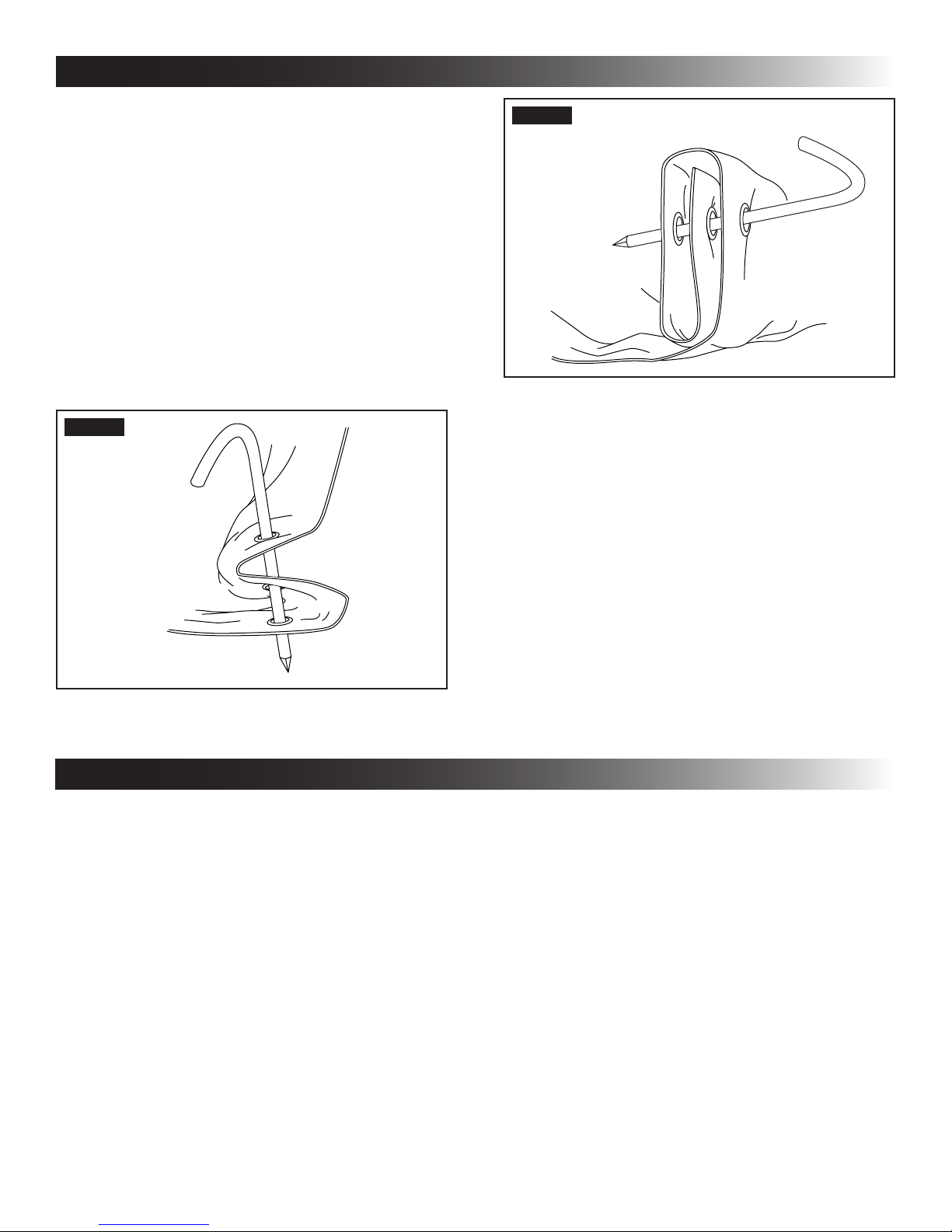
Since the Veranda Room comes in an adjustable
height, it is designed such that adjustment for
height can be achieved by shortening the bottom
of the panels. This is done by folding the excess
fabric at the bottom of the panels so that the
grommets line up with one another.
The fabric may be folded by folding back and
forth upon itself as shown in FIG. 17, or by rolling
the fabric as shown in FIG. 18. Either step is
repeated until fabric reaches the correct length
for the vehicle. After the correct length has been
established from inside the room through the
grommets, stake to the ground.
FIG. 17
FIG. 18
OPERATING INSTRUCTIONS
Do NOT operate appliances venting into this
room enclosure with privacy panels closed. At least one
panel MUST be open for ventilation when using appliances.
Death or serious injury from Carbon Monoxide Poisoning
could occur if NOT operated properly.
The privacy panels can be rolled up and fastened
with the use of straps to allow for ventilation of the
Veranada Room.
Skirting MUST not interfere with appliance
venting. Do NOT start or operate the RV engine or RV
generator if exhaust vents are located behind skirting.
Death or serious injury from Carbon Monoxide Poisoning
could occur if NOT operated properly.
If the RV is equipped with an automatic
entry step, make sure the automatic operation is disabled.
Make sure this step remains in the “down” or “extended”
position while installing and using the product.
During rain, lower the end furthest from the
door to allow water to ow off awning. Whenever heavy or
prolonged rain or wind is anticipated or you will leave the
awning and screen room unattended, it is best to remove
the screen room and close the awning. Damage as a result
of weather is NOT covered by warranty.
When the awning is relatively at and the screen
room pole is in the lowest position, it should be rolled
up if rain is anticipated to prevent damages.
10
 Loading...