

Page 1
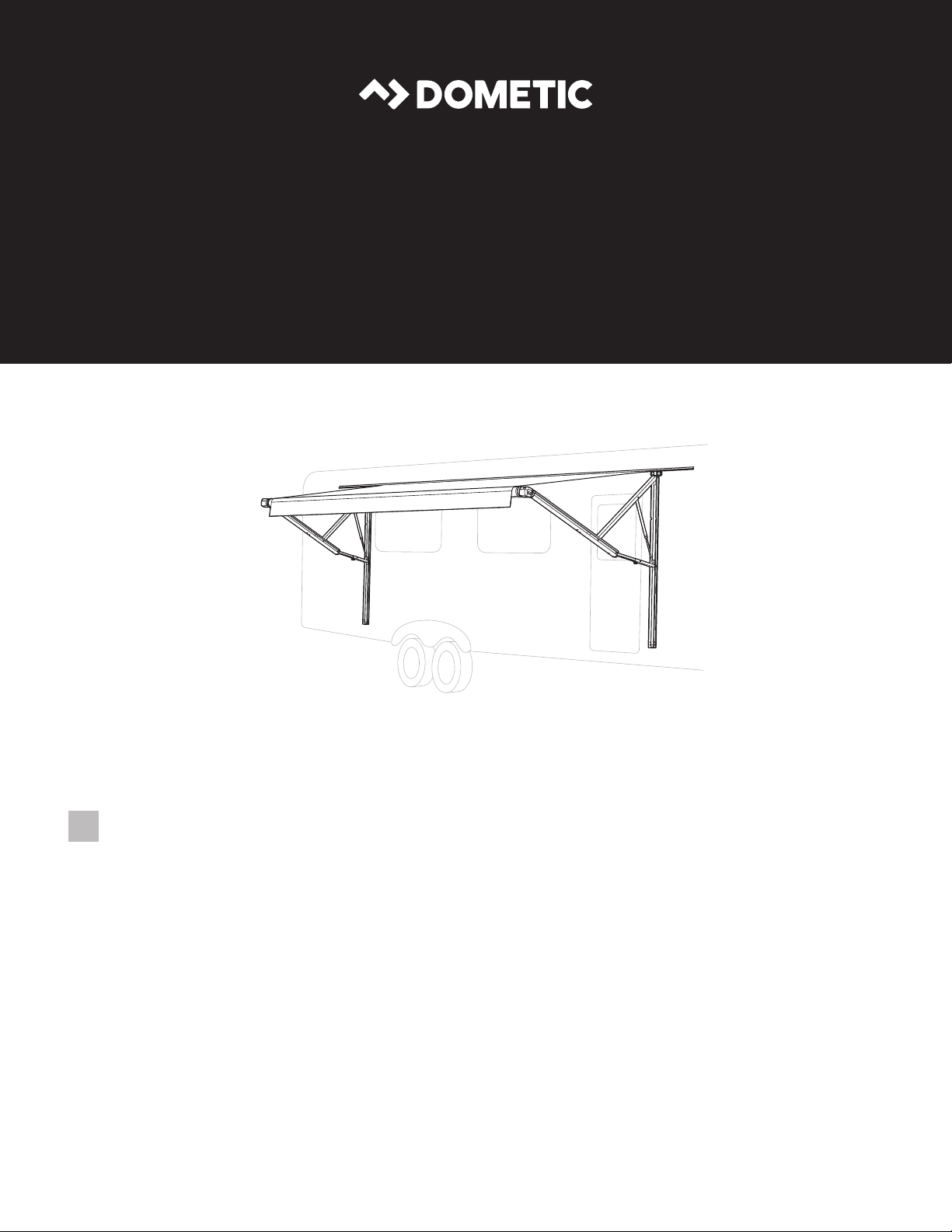
AWNINGS
POWER AWNING
9200 Series Power Awning
EN
Installation Instructions
9200 Model
Page 2

Power Awning
NORTH AMERICAN ADDRESS INFORMATION
USA & CANADA
Service Office
Dometic Corporation
1120 North Main Street
Elkhart, IN 46514
Form No. 3316600.000_A 7/18 | ©2018 Dometic Corporation
Read these instructions carefully. These instructions MUST stay with this product.
Service Center & Dealer Locations
Visit: www.dometic.com
CONTENTS
1 Explanation of symbols and safety instructions ................................................ 3
2 General information ..................................................................... 4
3 Intended use ........................................................................... 5
4 Specifications .......................................................................... 5
5 Pre-Installation .......................................................................... 6
6 Installing electric kits ..................................................................... 9
7 Installing the awning .................................................................... 10
8 Verifying the installation ................................................................. 16
EN
2
Page 3

Power Awning
1 EXPLANATION OF SYMBOLS AND SAFETY INSTRUCTIONS
This manual has safety information and instructions to help you eliminate or reduce the risk of accidents
and injuries.
1.1 Recognize safety information
This is the safety alert symbol. It is used to alert you to potential physical injury hazards. Obey all safety
messages that follow this symbol to avoid possible injury or death.
1.2 Understand signal words
A signal word will identify safety messages and property damage messages, and will indicate the degree or level
of hazard seriousness.
indicates a hazardous situation that, if not avoided, could result in death or serious injury.
indicates a hazardous situation that, if not avoided, could result in minor or moderate injury.
is used to address practices not related to physical injury.
indicates additional information that is not related to physical injury.
I
1.3 Supplemental directives
Read and follow all safety information and instructions to avoid possible injury or death.
Read and understand these instructions before installation of this product.
Incorrect installation of this product can lead to serious injury.
The installation must comply with all applicable local or national codes, including the latest edition of the
following standards:
U.S.A.
• ANSI/NFPA70, National Electrical Code (NEC)
• ANSI/NFPA 1192, Recreational Vehicles Code
Canada
• CSA C22.1, Parts l & ll, Canadian Electrical Code
• CSA Z240 RV Series, Recreational Vehicles
1.4 General safety messages
Failure to obey the following warnings could result in death or serious injury:
• This product must be installed and serviced by a qualified service technician.
• IMPACT OR CRUSH HAZARD:
– This awning should be installed in a controlled environment (inside). Do not install the awning during
windy conditions, or when wind is expected. Otherwise, the awning could move unpredictably, become
unstable, and could detach, bend, or collapse.
– Do not remove LED rail (if equipped) from awning fabric. Otherwise, awning fabric could separate from
awning rail (on RV) and cause the awning to extend quickly, resulting in detaching, bending, or collapsing.
Failure to obey this warning could result in death or serious injury.
• FIRE OR ELECTRICAL SHOCK HAZARD. Make sure there are no obstacles (wires, pipes, etc.) inside RV walls.
Shut OFF gas supply, disconnect 120 VAC power from RV, and disconnect positive (+) 12 VDC terminal from
supply battery before drilling or cutting into RV.
• IMPACT OR PINCH HAZARD. Do not remove straps (wrapped around each arm assembly) until roller tube is
secured to front channel, awning fabric is attached to awning rail, and arm assembly is mounted to RV. Arm
assemblies are under tension from gas strut. Removing these ties could allow arms to extend quickly and
unexpectedly. Failure to obey this warning could result in death or serious injury.
3
EN
Page 4

Power Awning
LIFTING HAZARD. Use proper liing technique and control when liing the awning. Failure to
obey this caution could result in injury.
Failure to obey the following notices could damage product or property:
• ALWAYS use sealant on clean parts and surfaces where fasteners enter RV walls. Otherwise, water leakage
could occur.
• Install back channels on a flat surface, level, and keep parallel with each other to ensure correct function and
appearance.
• This product is for use with 12 VDC only.
2 GENERAL INFORMATION
Included Parts Quantity
15 Amp Circuit Breaker 1
#14-10 x 1-1/2" Hex Head Screw 8
#6-20 x 7/16" Self-drilling Hex Head Washer Screw 2
Slic Pin 1
Hardware End Covers (# = B for White, # = U for Black):
4
• 3316607.002# Front Right
• 3316813.000# Back Right
• 3316608.002# Front Le
• 3316814.000# Back Le
Optional Parts* Reference Number
Door Roller Kit 830304
Back Channel Spacer Kit 3312853.025 (#)
Door Roller Kits (50 Pack) 830304.003
*Available as accessory (not included).
Required Tools
Drill
3/16” Drill Bit; 7/32” Drill Bit (For Steel Mounting)
3/8” Hex Driver (For Drill)
5/8” Drill Bit
EN
4
Page 5

Power Awning
3 INTENDED USE
This 9200 Series Power Awning (hereinaer referred to as ”Awning”) is designed and intended for installation on
a Recreational Vehicle (hereinaer referred to as “RV”) during or aer the RV manufacture. Use these instructions
to ensure correct installation and function of the product.
The Product kit is available for order with various components, so while some graphics may show different
components, they still illustrate the correct procedure. All components that were not originally ordered can be
purchased as an add-on or upgrade.
The manufacturer accepts no liability for damage in the following cases:
• Faulty assembly or connection.
• Damage to the product resulting from mechanical influences and excess voltage.
• Alterations to the product without express permission from the manufacturer.
• Use for purposes other than those described in the operating manual.
Dometic Corporation reserves the right to modify appearances and specifications without notice.
4 SPECIFICATIONS
4.1 Hardware dimensions (back channel)
8962XX1.4X0#(L) 8962XX2.4X0#(L) 8962XX3.4X0#(L)
A
B
C
D
E
F
G
H
K
L
M
62 3/4" 66 1/4" 66 1/4"
62 1/8" 65 5/8 65 5/8"
60 1/8" 63 5/8" 63 5/8"
60 3/4" 64 1/4" 64 1/4"
61 1/2" 65" 65"
33"
39"
3/8"
J
1/4"
5/8"
3/4"
1 1/2"
Wiring harness location may be at the top or
I
bottom of the back channel, depending on
the awning model.
1
C
B
A
K
Top Wiring
Harness Notch
M
F
G
Bottom
Wiring
Harness
Hole
J
H
L
E
D
5
EN
Page 6
Power Awning
4.2 Door clearance
When the entry door is toward the center of the awning, add 2” to minimum distances.
I
Model Min. Distance (X)
8962XX1.4X0#(L) 12"
8962XX2.4X0#(L) 7"
8962XX3.4X0#(L) 6"
Doors, windows, lights, trim, slideout rooms,
I
etc. must be considered when determining
the length and position of the awning to
ensure that the awning will not obstruct them
or be affected by them.
2
Awning Rail
X
Entry Door
5 PRE-INSTALLATION
5.1 Installing the roller and edge guard (optional)
Do not allow the corner of the entry door to contact the awning fabric. Otherwise, premature
wear or tearing of the awning fabric could occur. If there’s potential for a squared corner entry door to contact
the awning fabric, a door roller kit (not included) must be installed. Failure to obey this notice could result in
damage to the product or property.
3
4
1/4" – 3/8"
(Above Door)
Outer Entry Door
Door Edge Guard
Inner Screen Door
EN
6
Page 7

Power Awning
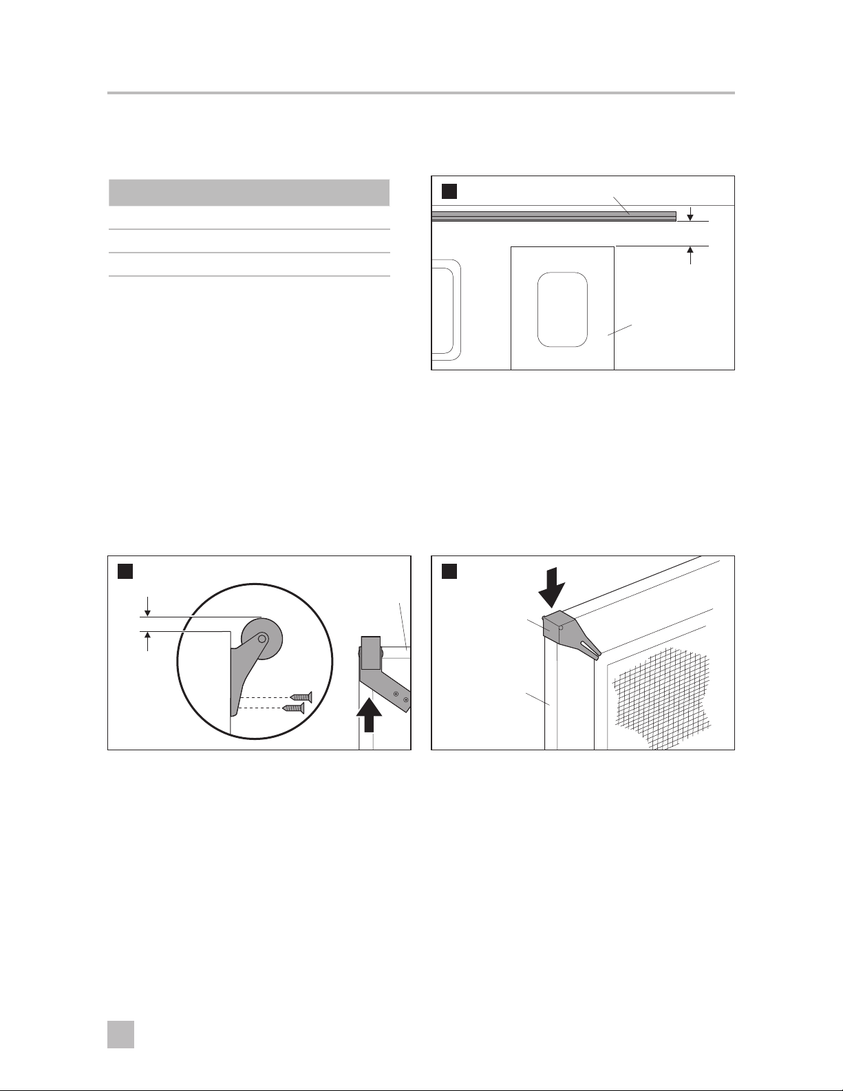
5.2 Preparing the awning rail for fabric insertion
Ensure the awning rail is parallel to the RV floor, and is not warped or curved, before installing
the awning fabric. If the awning rail is not straight, the awning fabric may wrinkle or stretch. Failure to obey this
notice could result in damage to the product or property.
5
➤ Select a rail end (on the RV) to insert the awning
fabric. Flare (widen) the top and bottom of that
end with a flat-bladed screwdriver, and remove
(file) any burrs or sharp edges.
If awning is equipped with LED lights, flare the
I
top of the awning rail end only.
LED Awning
(Top Only)
Typical Awning
(Top and Bottom)
5.3 Preparing the awning for installation
Read before proceeding:
I
– The motor is already installed on the RH arm assembly.
– The motor and the Slic pin cannot be removed once they are installed.
➤ Place the fabric roller tube assembly (FRTA) on a protected surface while preparing it for installation.
6
FRTA
➤ After m
7
otor is installed, pull motor away from
Roller tube to verify that it is engaged.
RH End Cap
Motor Drive Sha
7
Top
Casting
Slic Pin
LH End Cap
FRTA
EN
Page 8

Power Awning
5.4 Determining the awning location
IMPACT OR CRUSH HAZARD. Make sure mounting surface on RV is flat, has solid structural
backing where fasteners penetrate surface, and will safely and securely support awning. Otherwise, awning may
become unstable and could detach. Failure to obey this warning could result in death or serious injury.
8
Allow for sufficient clearance between the
I
awning fabric and the entry door, or slideout
room, to accommodate awning pitch (slope).
Avoid locations that interfere with entry
door swing when the awning is completely
extended.
➤ Find a solid structure in the RV wall to support
the top mounting brackets and back channels (all
mounting points.
➤ To install over windows, order back channel
spacer kit P/N 3312853.025(#).
Make sure arm assemblies do not restrict the
I
use of doors, windows, etc.
EN
8
Page 9

Power Awning
6 INSTALLING ELECTRICAL CONNECTIONS
ELECTRICAL SHOCK HAZARD. Failure to obey the following warnings could result in death or
serious injury:
• Disconnect all electrical connections from the RV.
• Awning must be on a 12 VDC 15 Amp protected, dedicated circuit.
Disconnect the positive (+) 12 VDC terminal from the supply battery. Failure to obey this notice
could result in damage to the product or property.
➤ Disconnect power for ALL procedures under this section.
6.1 Installing the awning switch (fixed/wired)
Do not expose the switch to weather, extreme temperatures, or long hours in direct sunlight.
Find a suitable location for awning switch installation. Failure to obey this notice could result in damage to the
product or property.
Read before proceeding:
I
– Use the correct (Dometic Corporation approved) momentary switch, or an electronic control switch with
motor overload protection.
– See instructions included with your Dometic Corporation switch kit for additional wiring instructions.
➤ Install the 15 Amp circuit breaker (included) at the fuse panel for positive (+) 12 VDC power supply (RED wire)
to switch. Otherwise, damage to the awning could occur.
➤ Route wiring (inside RV) to a general location where connections to the awning hardware will be made. Allow
enough wiring length to pass through the outside RV wall (hole will be drilled later) for connection to the
awning.
➤ The wiring hole location will be either at the top or the bottom of the RH back channel, depending on the
awning model.
➤ Make the appropriate wiring connections inside RV. Wiring connections to the awning (through outside RV
wall) will be made later.
6.2 Installing the ignition/safety interlock system
IMPACT OR CRUSH HAZARD. Do not install the awning without also installing an ignition/
safety interlock system. Otherwise, accidental operation during transit could occur. Failure to obey this warning
could result in death or serious injury.
Install a (3 A) fuse (installer supplied) at the fuse panel for positive (+) 12 VDC ignition control (
PINK wire) to ignition interlock. Failure to obey this notice could result in damage to the product or property.
Read before proceeding:
I
– Ignition/safety interlock system is only applicable to motorhomes.
– The ignition interlock MUST break the circuit (cut power) to the awning when the ignition is ON.
➤ Make the appropriate wiring connections. See instructions included with your Dometic Corporation ignition
interlock kit for additional wiring instructions.
9
EN
Page 10

Power Awning
6.3 Installing the led light switch (if applicable)
Do not expose the switch to weather, extreme temperatures, or long hours in direct sunlight.
Failure to obey this notice could result in damage to the product or property.
An LED light switch (installer supplied) is required for awning models equipped with an LED light strip.
I
➤ Find a suitable location for LED switch installation.
➤ Install a (3 A) fuse or a (3A) in-line fuse (installer supplied) at the fuse panel for positive (+) 12 VDC power
supply ( RED wire) to switch. Otherwise, damage to the awning could occur.
➤ Route wiring (inside the RV) to a general location where connections to the awning hardware will be made.
Allow enough wiring length to pass through the outside RV wall (hole will be drilled later) for connection to
the awning.
➤ Wiring hole location will be either at the top or the bottom of the RH back channel, depending on the awning
model.
➤ Make appropriate wiring connections inside the RV. See instructions included with your LED light switch for
specific wiring instructions.
Wiring connections to the awning (through the outside RV wall) will be made later.
I
7 INSTALLING THE AWNING
7.1 Inserting the awning fabric into the awning rail
Keep both arm assemblies parallel to each other to avoid twisting and damaging the awning.
Failure to obey this notice could result in damage to the product or property.
You will need at least two other people to hold and control the hardware until top mounting brackets and
I
back channels are correctly installed. You may also need a stepladder.
9
Awning Rail
Hardware
Arm Assembly
➤ While one person guides the awning fabric (with
awning roller cover, if equipped) into the awning
rail, carefully move (carry) the awning hardware
assembly to its desired location.
➤ With one person grasping each arm assembly,
carefully li the entire awning assembly upright.
Then carry the awning toward the prepared (flared)
awning rail end.
If an LED light strip is not desired, standard
I
fabric MUST be used. Otherwise, you may
remove the LED light strip from the LED rail,
and leave the empty LED rail on fabric rope.
FRTA
10
Awning Fabric
➤ Unfurl the awning fabric one revolution before
inserting the fabric (with the awning roller cover,
if equipped) into the awning rail. Unfurling one
revolution will allow enough space between the
RV wall and the awning hardware to guide the
awning fabric into the awning rail.
➤ Slide the awning fabric into the awning rail while
carrying the awning toward the other (non-flared)
end.
Awning Rail
EN
10
Page 11

Power Awning
7.2 Attaching the top mounting brackets
IMPACT OR PINCH HAZARD. Arm assemblies are under tension from gas struts. Hold arm
assemblies and FRTA securely BEFORE removing ties. Otherwise, arms will extend quickly and unexpectedly.
Failure to obey this warning could result in death or serious injury.
Control both arm assemblies while installing brackets. When the weight of the FRTA is not
supported, downward force could cause arm assemblies to swing sideways and damage the RV. Failure to obey
this notice could result in damage to the product or property.
The motorized arm assembly is ALWAYS installed at the RH side of awning.
I
11
Wide Awning Rail
Top Mounting
Bracket
Some awning rails have a wide drip channel
I
to catch water as it runs off the RV roof. It may
be necessary to lower the position of the top
mounting brackets to avoid interference.
13
Top Notch
(Channel)
12
FRTA
Awning
Rail
Top Mounting
Brackets
➤ While holding the arm assemblies securely in
place and perpendicular to the awning rail, mark
the top set of the mounting hole locations.
14
Sealant
Bottom Hole
(Channel)
➤ Drill 3/16" diameter holes through the marked
mounting hole locations and into the solid
structure of the RV. (Drill 7/32" diameter holes if
drilling through steel.)
The wiring harness hole location is determined
I
by awning model. The back channel will either
have a notch at top, or a hole near the bottom
for wiring to pass through the RV wall.
➤ If the wiring hole location is the bottom of the
RH bracket, then skip this step. If the wiring hole
location is at the top of the RH bracket, mark the
location and drill a 5/8" diameter hole.
11
#14-10 x 1-1/2"
Hex Head Screw
➤ Apply sealant to the threads on two
#14-10 x 1-1/2" screws.
➤ Place and tighten one screw through the upper
outside slot of the RH top mounting bracket and
into the solid structure of the RV.
➤ Repeat on the LH side.
Ensure the arm assemblies are completely
I
closed before tightening the outside screws.
Closed arm assemblies will help in the overall
alignment of the awning.
EN
Page 12

Power Awning
15
➤ Remove the straps from the hardware arms and
slowly unfurl the awning 12" – 18".
➤ Apply sealant to the threads on two #14-10 x
1-1/2" screws.
➤ Place and tighten one screw through the inside
upper slot of the RH top mounting bracket and
into the solid structure of the RV.
➤ Repeat on the LH side.
Strap
EN
12
Page 13

Power Awning
7.3 Attaching the back channels
16
Wiring Cover
➤ Remove the wiring cover from the RH back
channel (if applicable).
Set aside the wiring cover for reinstallation later.
I
18
Marked Mounting
Hole Locations
RH Arm
Assembly
17
FRTA
Floor Lines
➤ Square the RH back channel to the RV and the
FRTA. Then mark the mounting hole locations.
Repeat on the LH side.
Center
Mounting
Holes
Bottom
Mounting
Holes
Sealant
#14-10 x
1-1/2" Screw
➤ Swing the RH assembly out of the way to expose
the marked hole locations. If necessary, loosen the
inside screw of the top mounting bracket.
➤ Drill 3/16" diameter holes (7/32" diameter holes
if drilling into steel ) through the marked mounting
hole locations.
➤ If you are attaching the LH back channel, or if the
wiring will pass through the RV wall at the TOP of
the RH back channel, then skip this step. Drill a 5/8"
diameter hole at the marked BOTTOM wiring hole
location and through the outside wall of the RV.
Swing the back channel back into place.
I
Retighten the screw on the top mounting
bracket, if necessary.
➤ Apply sealant to the #14-10 x 1-1/2" screws (oscar
rivets are an acceptable alternative). Place the
screws through the bottom mounting holes of the
back channel, and secure to the RV.
Structural backing (with skin) MUST be 3/8"
I
to 1/2" thick to accommodate the screws. Use
structural screws to secure the back channel if
the RV has structural backing that supports at
least 100 lb. of force per screw.
➤ Repeat these steps for the LH arm assembly.
13
EN
Page 14

Power Awning
7.4 Making electrical connections to the awning
Failure to obey the following notices could damage the awning or other property:
• Make sure the positive (+) 12 VDC terminal is disconnected from the supply battery. Otherwise, damage to
the awning could occur.
• Always seal wiring against weather and moisture where wiring enters the RV wall, roof or floor. Otherwise,
water leakage could occur.
• Do not pinch wiring or allow wiring to rub against sharp edges. If wiring is damaged, it MUST be replaced by
a qualified service technician.
19
Grommet
Use a grommet or heat-shrink tubing where
I
wiring passes through the RV wall. If a grommet
is not used, make sure sealant will also provide
effective and permanent protection against
wire damage.
Motor And Switch Connections:
➤ Plug the motor wire into the motor wire harness at
the top of the front arm.
➤ Pull the wiring through the wiring hole and
grommet, and connect to appropriate wiring
inside the RV. Make proper electrical connections
inside the RV.
➤ Secure any slack motor/hardware wiring inside
the front channel to prevent pinched or damaged
wiring during awning operation.
See instructions included with your Dometic
I
Corporation switch kit for additional wiring
instructions.
RV Wall
Wiring
20
LED Light Connections (If Equipped):
Skip this step if the awning is not equipped
I
with an LED light strip.
➤ Pull the wiring through the wiring hole and
grommet. If a grommet is not used, make sure
sealant will also provide effective and permanent
protection against wire damage.
➤ Connect the LED switch wiring to the factory
prewired LED light strip.
➤ Secure the wiring to prevent pinching or other
damage during awning operation. Allow enough
slack in the wiring to safely accommodate possible
fabric movement.
See instructions included with your LED switch
I
kit (installer supplied) for additional wiring
instructions.
LED Connector
Hardware
Connector
EN
14
Page 15

Power Awning
7.5 Completing the back channel installation
PINCH HAZARD. Maintain a horizontal distance of at least 16" between the fully open awning
and any permanent object. Failure to obey this caution could result in injury.
21
➤ Restore power and fully retract the awning.
➤ Verify that the front and back channels are aligning
properly.
➤ Open the awning (fully extend). See “Open
Awning” in the Operating Instructions.
➤ Verify that the back channel is still square with the
RV and FRTA.
22
Wiring Cover
➤ Disconnect the 120VAC power from the RV and
disconnect the positive (+) 12VDC power terminal
from the supply battery.
➤ Using one pair of center mounting holes as a
guide, drill 3/16" diameter holes into the solid
structure of the RV. Drill 7/32" diameter holes if
drilling into steel. The center mounting holes may
be above or below the strut.
The wiring cover (if present) MUST be
I
removed from the RH back channel to access
the center mounting holes.
➤ Verify that the wiring is not caught between the
hardware and the RV wall before tightening the
fasteners.
➤ Apply sealant to #14-10 x 1-1/2" screws (oscar
rivets are an acceptable alternative). Then place
the screws through the back channel (center
mounting holes) and secure to the solid structure
of the RV.
➤ Structural backing (with skin) MUST be 3/8"to
1/2" thick to accommodate the screws.
➤ Re-install the wiring cover set aside in section “7.3
Attaching the back channels” on page 13.
Sealant
Mounting
Hole
Back
Channel
#14-10 x
1-1/2" Screw
15
Repeat these steps on the LH bracket, then
I
reconnect the power.
EN
Page 16

Power Awning
7.6 Securing the awning to the railing
23
➤ Open and close the awning 4 – 5 times.
➤ Verify alignment and hardware nesting. Adjust the
hardware if necessary.
Repeat this procedure as needed.
I
7.7 Installing the plastic covers
25
Plastic Cover
Plastic Cover
24
Awning
Fabric Edge
➤ Pull the right edge of the awning fabric
approximately 1/4" beyond its position. Then
secure the fabric with one #6 x 7/16" TEK screw
through awning rail (approximately 2" from the
fabric edge).
➤ Repeat for the LH side.
26
#6 x 7/16" TEK Screw
2"
Awning
Rail
LH RH
➤ Snap the plastic covers into position at each end of
the awning to complete the installation.
8 VERIFYING THE INSTALLATION
8.1 Testing operation
27
➤ With power applied to the awning, open and close the awning to verify that each part is functioning correctly.
Refer to the Operating Manual for securing the awning for travel.
I
EN
16
Page 17

Power Awning
17
EN
 Loading...