

Dometic 9093200-(X)PR, 9093100-CPR, 9093100-EPR, 9093100-WPR, 9093200-CPR Installation And Operating Instructions Manual
...Page 1
Seller
Dometic AB
T orggatan 8
SE-171 54 Solna
(Stockholm)
Phone +46 8 501 025 00
Fax +46 8 501 025 99
Email info@dometic.se
CENTRAL RV VACUUM
RECORD THIS INFORMATION FOR FUTURE REFERENCE
BEFORE INSTALLING THE UNIT:
Model Number
Serial Number
Date Purchased
Place of Purchase
CENTRAL RV V ACUUM
9093100-(X)PR FLUSH MOUNT
9093200-(X)PR EXTERNAL MOUNT
Replace (X) with color code from model chart on page 2
WARNING
!
This manual must be read and
understood before installation,
adjustment, service, or maintenance is performed. This unit must
be installed by a qualified service
technician. Modification of this
product can be extremely hazardous and could result in personal
injury or property damage.
INST ALLA TION & OPERA TING
INSTRUCTIONS
Form No. 3308407.000 4/03
©2003 Dometic AB
Torggatan 8 SE-171 54 Solna
Important: Instructions
must stay with unit.
Owner read carefully.
MODEL
9093100-(X)PR
9093200-(X)PR
1
Page 2
SAFETY INSTRUCTIONS
This manual has safety information and instructions to help users eliminate or reduce the risk of
accidents and injuries.
RECOGNIZE SAFETY INFORMATION
!
CENTRAL RV VACUUM
This is the safety-alert symbol. When you see this
symbol in this manual, be alert to the potential for
personal injury .
Follow recommended precautions and safe operating instructions.
UNDERSTAND SIGNAL WORDS
A signal word , WARNING OR CAUTION is used
with the safety-alert symbol. They give the level of
risk for potential injury .
WARNING
!
ous situation which, if not avoided, could result in
death or serious injury .
CAUTION
!
ous situation which, if not avoided may result in
minor or moderate injury .
indicates a potentially hazard-
indicates a potentially hazard-
CAUTION
symbol indicates, a potentially hazardous situation which, if not avoided may result in property
damage.
Read and follow all safety information and instructions.
used without the safety alert
2
Page 3
CENTRAL RV VACUUM
SPECIFICA TIONS:
Electrical Rating 240VAC 50/60 Hz, 1 Ph
Amp Draw 11 Amps
Minimum Wire Size 16 AWG
AC Circuit Protection 7.5 Amp
Installed Weight 12 Lbs.
Hose Length 8’ - 30’
Case Steel
Part List:
9093(X)00-(X)PR Vacuum
(4) Wood Screws*
(4) Painted Screws**
(1) Template**
powder coat
(1) Mounting Bracket*
(3) 3308150.006 Bags
(1) 3308172.000 Motor Filter
(1) 3303170.004 Exhaust Filter
(3) Wire Nuts**
* Designates supplied with external mount vacuum.
** Designates supplied with flush mount vacuum.
MODEL NUMBER CODE CHART
9093(X)00-(X)PR
1 = Flush Mount
2 = External Mount
W/Mtg Brkt
C = CREAM
E = EBONY
W = WHITE
P = POWDER COA T
R = RECREATION VEHICLE
T ools Required:
Screw Driver
Level
1/16” Drill Bit
Awl
Power Drill
Electrical Wire
Drywall Anchors
INSTALLATION
I. GENERAL INFORMA TION
A. This Central RV V acuum Cleaner is designed to be built
into a recreational vehicle at the time of manufacture;
or, with the use of an external mounting plate, it can be
installed in a recreational vehicle after it has been manufactured.
Read Installation and Operating Instructions carefully
before attempting to start your vacuum cleaner installation.
WARNING
!
Improper installation may damage equipment, could endanger life, cause serious injury and/or property damage.
B. LOCA TION:
1. External Mount Installation
a. To reach with vacuum hose as far as possible,
choose a wall or surface that is centrally located
and has an electrical outlet within 6 foot of
vacuum cleaner.
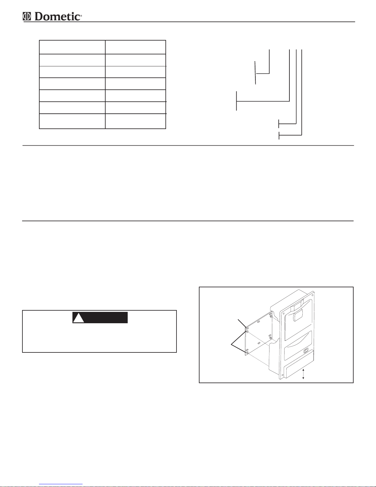
Attach mounting bracket to wall or surface at a
comfortable operating height or if not possible a
minimum of 6” above the floor. For hard surface
mounting, use the 4 outer holes with wood screws.
For drywall mounting, use 4 outer holes with drywall anchors (not supplied). See FIG . 1.
INST ALL MOUNTING
BRACKET WITH
SCREW HOLES
ABOVE KEYSTUDS
KEYSTUD
FIG. 1
6” MIN
CLEARANCE
c. Attach vacuum cleaner to the mounting bracket,
using the 4 keyholes in the back of the unit to the
4 studs on the mounting bracket, then slide unit
down into locked position.
d. Before plugging in the electrical cord, check to
be sure vacuum cleaner bag, motor filter, exhaust filter, and gate are in place. See Oper-
ating Instructions, Step s D, E, and F.
Note: Never use vacuum cleaner without dust bag
or motor filter in place.
3
Page 4

CENTRAL RV VACUUM
CAUTION
!
2. Flush Mount installation
a. To reach with vacuum hose as far as possible,
choose a wall or surface that is centrally located
and has a nearby 110 V olt AC power connection.
The vacuum cleaner requires 3-7/8” wall depth
(measured from the front of the wall).
WARNING
!
There may be electrical wiring in the wall.
Disconnect AC power cord and the positive
(+) 12 volt DC terminal at the supply battery. Failure to follow this instruction may
create a shock hazard causing death or severe personal injury .
b. Attach paper template with tape to wall or sur-
face a minimum of 6“ above the floor, if mounted
in a vertical position. This will allow sufficient clearance for exhaust air. See FIG. 2.
FIG. 2
CUT OUT
OPENING
7-3/4” x 15-7/8”
WALL
T APE TEMPLATE
TO W ALL
g. Test unit for operation before installing. Check to
be sure vacuum cleaner bag, motor filter, exhaust
filter and gate are in place. See Operating Instructions, Steps D, E, and F. Slide the unit , bottom
first into the opening and secure to wall with the 4
wood screws.
Note: Never use vacuum cleaner without dust bag
or motor filter in place.
Note: Optimal installation uses 6 wood screws
instead of 4 to reduce risk of loosening due to
road vibration.
C. GROUNDING INSTRUCTIONS - EXTERNAL MOUNT
1. This appliance must be grounded. If it should malfunction or breakdown, grounding provides a path of
least resistance for electric current to reduce the
risk of electric shock. See FIG. 3.
D. GROUNDING INSTRUCTIONS - FLUSH MOUNT
2. For permanently connected appliances, (in-wall installation) this appliance must be connected to a
grounded metal permanent wiring system; or an
equipment-grounded conductor must be run with
To avoid possible electrical shock, be sure
that electricity is turned off at the main switch
or circuit breaker.
FLOOR
6” MIN
CLEARANCE
c. T ape the template to the mounting surface of the
desired location. The bottom of the cut out must
be the minimum of 6” above the floor.
d. Center punch all of the circles with an awl or nail.
Remove the template. Draw a line connecting the
circles using a pencil and straight edge. This will
outline an area 7-3/4” x 15-7/8” that is to be cut
out.
e. Drill the 4 corner marks with a 1/16” drill bit, then
saw out the opening. Be sure to follow the line as
the mounting holes are close to the edge of the
cut out.
Note: Instructions also printed on paper template.
f. Place the vacuum cleaner upside down with its’
back towards you. Remove the 2-3/4 ”x 1-3/8”
cover plate on the vacuum cleaner. Inst all 16 A WG
cable (rated at 90
sheathed cable with ground (Romex) or flexible
metal conduit with ground, to electrical outlet.
(Check your local electrical code.) Make the
connection through the Romex clamp (do not
pinch wiring). Replace cover plate.
0
C) to the unit. Use nonmetallic
FIG. 3
the circuit conductors and connected to the equipment grounding terminal or lead on the appliance.
Note: All wiring must comply with the National Elec-
trical Code ANSI/NFP A 70-(latest edition); or CSA
St andard C22.1, Canadian Electric Code, Parts 1
and 2; and any applicable local codes.
4
Page 5

CENTRAL RV VACUUM
OPERATING INSTRUCTIONS
A. IMPORT ANT SAFETY INSTRUCTIONS
When using an electrical vacuum cleaner, basic precautions should always be followed including the following:
1. Read all instructions carefully before using this
vacuum cleaner.
2. Save these instructions.
WARNING
!
TO REDUCE THE RISK OF FIRE, ELECTRICAL SHOCK, OR INJURY:
1. Do not leave appliance plugged in. Unplug from outlet when not in use and before servicing.
2. Do not use outdoors or on wet surfaces.
3. Never operate this vacuum cleaner without a dust bag and filters in place.
4. Close attention is necessary when used by or near children. Do not allow unit to be
used as a toy.
5. Use only for intended use as described in this manual . Use only the manufacturer ’s
recommended attachments and dust bags.
6. Do not use with damaged cord or plug. If appliance is not working as it should, has been
dropped, damaged, left out doors, or dropped into water, return the vacuum cleaner to
Dometic or an authorized service dealer for examination and repair .
7. Do not put any object into openings. Do not use with any openings blocked; keep free
of dust, lint, hair and any other material that may reduce air flow. When the secondary
filter becomes dirty , rinse in warm water or replace with a new filter . Filters shall be completely dry before using.
8. Never drop or insert any object into any opening.
9. Turn off all controls before unplugging.
10. Do not pull or carry by the power cord, do not use power cord as a handle, do not close
a door on the power cord, or pull power cord around sharp edges or corners. Do not run
appliance over power cord. Keep power cord away from heated surfaces.
1 1. Do not unplug by pulling on power cord. To unplug, grasp the plug not the power cord.
12. Keep hair, loose clothing, fingers, and all parts of body away from any opening and
moving parts.
13. Do not pick up anything that is burning or smoking, such as cigarettes, matches or hot
ashes.
14. Use extra caution when cleaning on stairs.
15. Do not handle plug or appliance with wet hands.
16. Do not pick up flammable or combustible liquids such as gasoline, or use in areas where
they may be present.
17. Do not place objects against the vacuum cleaner. Keep area clear.
18. Do not step on the hose or pull the hose forcibly.
19. Do not pick up large objects such as waste paper or cloth, which may clog the hose.
20. Do not install this vacuum cleaner in an area exposed to high temperatures.
21. Install this vacuum cleaner in a dry place.
22. Do not attempt to service the vacuum cleaner. Unit is sealed and cannot be opened
without damage to the unit. For service, call your local authorized service dealer, or
Dometic.
5
Page 6

CENTRAL RV VACUUM
FIG. 4
DOOR LA TCH
INLET V ALVE
COVER
V ACUUM HOSE
UNIT CAN BE MOUNTED
ON SIDE OR BACK
B. A few minutes of operating of the vacuum cleaner will
result in the discharge of warm exhaust air. This is normal operation; however, a full dust bag or a dirty motor
filter can cause the motor to stop. If this occurs see
step H. Troubleshooting, points a - e.
WARNING
!
T o reduce the risk of fire, injury or damage:
Do not pick up lit cigarettes, hot ashes, razor blades, needles, pins or other sharp objects.
C. CONNECTING AND DISCONNECTING HOSE
1. Lift up the inlet valve cover on the front door panel.
2. Insert hose with a slight twist motion in either direction.
3 Removal of hose is done with a twist motion in ei-
ther direction, while pulling outward. See FIG . 4.
D. STARTING AND STOPPING VACUUM CLEANER
1. Start the vacuum by pushing the switch to the “ON”
position. See FIG. 4.
2. Stop the vacuum cleaner by pushing the switch to
the “OFF” position. See FIG. 4.
E. CHANGING DUST BAG
1. Remove the vacuum cleaner door by pushing the
latch up. See FIG. 4.
2. Push the new bag onto the door’s scoop shaped
pipe as far as possible. See FIG. 5.
3. Slide bottom of bag into vacuum cleaner cavity, then
place bottom of door in the front panel slots.
MODEL LABEL
INSIDE
DUST BAG
FRONT PANEL
SWITCH
4. Tuck in the left and right corners of the bag so the
door can close. Close the door, then push down on
latch when it is in place the door is sealed and the
vacuum cleaner is ready for use. See FIG . 4.
5. When removing a full bag reverse the installation
procedure.
Note: Accidental spilling of the content s of the dust
bag can be prevented by leaving it attached to the
door. Carry both door and dirt bag to the trash, where
the dirt bag can be removed.
Note: Part number for the dust bag is 3308150.006,
a package of 3 dust bag is 3308169.006 and the 10
count package is 3308165.004 {a package of 10
dust bags contains (2) 3308172.000 motor filters
and (1) 3308170.004 exhaust filter}. Every fifth
change of bag replace motor filter, or when the white
part of filter is very dirty . Filter can be hand washed.
Contact your nearest Dometic Dealer for replacements.
FIG. 5
DOOR
PUSH DUST BAG ON
SCOOP AS FAR AS
POSSIBLE
DUST BAG
6
Page 7

CENTRAL RV VACUUM
CAUTION
F. CHANGING MOTOR FIL TER
1. Remove completely the door with the dust bag.
2. Remove the motor filter from the bottom of the
vacuum cleaner cavity . See FIG . 6.
3. Install the new motor filter with dark side up. Tuck
in the corners so that the filter lays flat on the grid
in the cavity .
Note: Clean the dirty motor filter by washing in mild
soap by hand. Do not machine wash. Let filter air
dry before replacing. See note in Step D Changing
Dust Bag.
FIG. 6
MOTOR FIL TER
WITH DARK
SIDE UP
G. CHANGING EXHAUST FIL TER
1. The exhaust filter is located in the opening at the
bottom of the vacuum cleaner front panel.
2. Push the plastic pins on the gate upward, then pull
the gate frame forward and down. See. FIG . 7.
3. Turn the switch to “ON” to start the vacuum cleaner.
The exhaust of the vacuum cleaner should blow the
exhaust filter out the opening. Turn the vacuum
cleaner “OFF”. See FIG. 4.
FRONT
P ANEL
FIL TER MUST
LA Y FLA T ON
GRILL TUCK
CORNERS IN
H. TROUBLESHOOTING
1. If your motor stops check the following:
a. Vacuuming large amounts of dust other than
household dirt, (drywall dust, fine wood dust,
etc.) can block the pores of the dust bag rap-
idly even if the dust bag is new.
b. The vacuum hose could be clogged.
c. The vacuum tool could be clogged.
d. The motor filter is dirty and should be cleaned
or replaced.
e. The exhaust filter should be checked and
cleaned or replaced.
All Dometic built-in vacuum systems are
equipped with a thermal overload protector
at the motor to prevent overheating. If the
motor stops, indicating overheating, push
the switch to the “OFF” position and check
the above Troubleshooting 5 points. The
motor will reset itself after about 1-1/2 hours.
If the problem should reoccur more than 3
times, please call the factory or selling dealer.
FIG. 7
FRONT
P ANEL
EXHAUST
FIL TER
GA TE
7
Page 8

CENTRAL RV VACUUM
LIMITED W ARRANTY
For Dometic Central V acuum Systems
THE SELLER NAMED BELOW MAKES THE FOLLOWING WARRANTY WITH
RESPECT TO THIS DOMETIC CENTRAL VACUUM SYSTEM
1. This Warranty is made only to the first Purchaser ( hereinafter called the “Original Purchaser”) who
acquires this product for his own use.
2. This Warranty will be in effect for three years on parts and freight and two years on labor from the date of
purchase by the Original Purchaser. It is suggested that the Original Purchaser retain a copy of the dated bill
of sale as evidence of the date of purchase.
3. This Warranty covers only specified parts which shall be free from defects in material and workmanship
under normal use. This Warranty does not cover conditions unrelated to the material and workmanship of
the product. Such unrelated conditions include, but are not limited to (a) faulty installation and any damage
resulting from such; (b) the need for normal maintenance and any damage resulting from the failure to
provide such maintenance; (c) failure to follow Seller’s instructions for use of product, and (d) any accident to,
or misuse of any part of this product and any alteration by anyone other than Seller or the authorized representative.
4. In order to obtain the benefits of this Warranty, you should return the product which you find defective to
your dealer during the period that this Warranty is in effect. All charges incurred in delivery of the central
vacuum system to the Seller must be paid by the Original Purchaser. A copy of the dated bill of sale must
accompany the returned product.
5. Any item returned in the manner described in paragraph 4 will be examined by your dealer. If it is found
that the central vacuum system is defective in material and workmanship, the Seller will replace the appliance.
6. The Seller does not authorize any person or company to create an warranty obligation or liability on their
behalf.
7. IN NO EVENT SHALL SELLER BE LIABLE FOR INCIDENT AL OR CONSEQUENTIAL DAMAGES, SOME
ST A TES DO NOT ALLOW THE EXCLUSION OR LIMIT A TION OF INCIDENTAL OR CONSEQUENTIAL DAMAGES SO THE ABOVE LIMIT A TION MAY NOT APPL Y TO YOU.
8. ANY IMPLIED WARRANTY, INCLUDING THE IMPLIED W ARRANTY OF MERCHANTABILITY AND FITNESS FOR ANY PURPOSE, IS LIMITED TO THE DURA TION OF THIS LIMITED W ARRANTY. SOME ST A TES
DO NOT ALLOW LIMITA TIONS ON HOW LONG AN IMPLIED WARRANTY LASTS, SO THE ABOVE LIMIT A TION
MAY NOT APPL Y TO YOU.
9. THIS WARRANTY GIVES YOU SPECIFIC LEGAL RIGHTS, AND YOU MA Y ALSO HA VE OTHER RIGHTS
WHICH VAR Y FROM ST A TE TO ST A TE.
10. All appliances (except those specifically built for commercial use) are warranted only when installed in
vehicles built to the R.V.I.A. and CSA Standards.
Seller
Dometic AB
T orggatan 8
SE-171 54 Solna
(Stockholm)
Phone +46 8 501 025 00
Fax +46 8 501 025 99
Email info@dometic.se
8
 Loading...