

Dodge Emissions Control 3500 2005, Emissions Control 2500 2005, Emissions Control 1500 2005 Service Manual
Page 1

DR/DH EMISSIONS CONTROL 25 - 1
EMISSIONS CONTROL
TABLE OF CONTENTS
page page
EMISSIONS CONTROL
DESCRIPTION
DESCRIPTION - STATE DISPLAY TEST
MODE ...............................1
DESCRIPTION - CIRCUIT ACTUATION TEST
MODE ...............................1
DESCRIPTION - DIAGNOSTIC TROUBLE
CODES ..............................1
DESCRIPTION - TASK MANAGER ..........2
DESCRIPTION - MONITORED SYSTEMS ....2
DESCRIPTION - TRIP DEFINITION .........4
DESCRIPTION - COMPONENT MONITORS . . . 5
OPERATION
OPERATION ..........................5
OPERATION - TASK MANAGER ...........6
OPERATION - NON-MONITORED CIRCUITS . 10
EVAPORATIVE EMISSIONS ................11
EXHAUST GAS RECIRCULATION ...........46
EMISSIONS CONTROL
DESCRIPTION
DESCRIPTION - STATE DISPLAY TEST MODE
The switch inputs to the Powertrain Control Module (PCM) have two recognized states; HIGH and LOW. For this
reason, the PCM cannot recognize the difference between a selected switch position versus an open circuit, a short
circuit, or a defective switch. If the State Display screen shows the change from HIGH to LOW or LOW to HIGH,
assume the entire switch circuit to the PCM functions properly. Connect the DRB scan tool to the data link connector and access the state display screen. Then access either State Display Inputs and Outputs or State Display
Sensors.
DESCRIPTION - CIRCUIT ACTUATION TEST MODE
The Circuit Actuation Test Mode checks for proper operation of output circuits or devices the Powertrain Control
Module (PCM) may not internally recognize. The PCM attempts to activate these outputs and allow an observer to
verify proper operation. Most of the tests provide an audible or visual indication of device operation (click of relay
contacts, fuel spray, etc.). Except for intermittent conditions, if a device functions properly during testing, assume the
device, its associated wiring, and driver circuit work correctly. Connect the DRB scan tool to the data link connector
and access the Actuators screen.
DESCRIPTION - DIAGNOSTIC TROUBLE CODES
A Diagnostic Trouble Code (DTC) indicates the PCM has recognized an abnormal condition in the system.
Remember that DTC’s are the results of a system or circuit failure, but do not directly identify the failed
component or components.
BULB CHECK
Each time the ignition key is turned to the ON position, the malfunction indicator (check engine) lamp on the instrument panel should illuminate for approximately 2 seconds then go out. This is done for a bulb check.
OBTAINING DTC’S USING DRB SCAN TOOL
1. Obtain the applicable Powertrain Diagnostic Manual.
2. Obtain the DRB Scan Tool.
3. Connect the DRB Scan Tool to the data link (diagnostic) connector. This connector is located in the passenger
compartment; at the lower edge of instrument panel; near the steering column.
Page 2

25 - 2 EMISSIONS CONTROL DR/DH
4. Turn the ignition switch on and access the “Read Fault” screen.
5. Record all the DTC’s and “freeze frame” information shown on the DRB scan tool.
6. To erase DTC’s, use the “Erase Trouble Code” data screen on the DRB scan tool. Do not erase any DTC’s
until problems have been investigated and repairs have been performed.
DESCRIPTION - TASK MANAGER
The PCM is responsible for efficiently coordinating the operation of all the emissions-related components. The PCM
is also responsible for determining if the diagnostic systems are operating properly. The software designed to carry
out these responsibilities is call the ’Task Manager’.
DESCRIPTION - MONITORED SYSTEMS
There are new electronic circuit monitors that check fuel, emission, engine and ignition performance. These monitors use information from various sensor circuits to indicate the overall operation of the fuel, engine, ignition and
emission systems and thus the emissions performance of the vehicle.
The fuel, engine, ignition and emission systems monitors do not indicate a specific component problem. They do
indicate that there is an implied problem within one of the systems and that a specific problem must be diagnosed.
If any of these monitors detect a problem affecting vehicle emissions, the Malfunction Indicator Lamp (MIL) will be
illuminated. These monitors generate Diagnostic Trouble Codes that can be displayed with the MIL or a scan tool.
The following is a list of the system monitors:
• Misfire Monitor
• Fuel System Monitor
• Oxygen Sensor Monitor
• Oxygen Sensor Heater Monitor
• Catalyst Monitor
• Leak Detection Pump Monitor (if equipped)
All these system monitors require two consecutive trips with the malfunction present to set a fault.
Refer to the appropriate Powertrain Diagnostics Procedures manual for diagnostic procedures.
The following is an operation and description of each system monitor :
OXYGEN SENSOR (O2S) MONITOR
Effective control of exhaust emissions is achieved by an oxygen feedback system. The most important element of
the feedback system is the O2S. The O2S is located in the exhaust path. Once it reaches operating temperature
300° to 350°C (572° to 662°F), the sensor generates a voltage that is inversely proportional to the amount of oxygen in the exhaust. The information obtained by the sensor is used to calculate the fuel injector pulse width. This
maintains a 14.7 to 1 Air Fuel (A/F) ratio. At this mixture ratio, the catalyst works best to remove hydrocarbons (HC),
carbon monoxide (CO) and nitrogen oxide (NOx) from the exhaust.
The O2S is also the main sensing element for the Catalyst and Fuel Monitors.
The O2S can fail in any or all of the following manners:
• slow response rate
• reduced output voltage
• dynamic shift
• shorted or open circuits
Response rate is the time required for the sensor to switch from lean to rich once it is exposed to a richer than
optimum A/F mixture or vice versa. As the sensor starts malfunctioning, it could take longer to detect the changes
in the oxygen content of the exhaust gas.
The output voltage of the O2S ranges from 0 to 1 volt. A good sensor can easily generate any output voltage in this
range as it is exposed to different concentrations of oxygen. To detect a shift in the A/F mixture (lean or rich), the
output voltage has to change beyond a threshold value. A malfunctioning sensor could have difficulty changing
beyond the threshold value.
Page 3

DR/DH EMISSIONS CONTROL 25 - 3
OXYGEN SENSOR HEATER MONITOR
If there is an oxygen sensor (O2S) shorted to voltage DTC, as well as a O2S heater DTC, the O2S fault MUST be
repaired first. Before checking the O2S fault, verify that the heater circuit is operating correctly.
Effective control of exhaust emissions is achieved by an oxygen feedback system. The most important element of
the feedback system is the O2S. The O2S is located in the exhaust path. Once it reaches operating temperature
300° to 350°C (572 ° to 662°F), the sensor generates a voltage that is inversely proportional to the amount of
oxygen in the exhaust. The information obtained by the sensor is used to calculate the fuel injector pulse width. This
maintains a 14.7 to 1 Air Fuel (A/F) ratio. At this mixture ratio, the catalyst works best to remove hydrocarbons (HC),
carbon monoxide (CO) and nitrogen oxide (NOx) from the exhaust.
The voltage readings taken from the O2S sensor are very temperature sensitive. The readings are not accurate
below 300°C. Heating of the O2S sensor is done to allow the engine controller to shift to closed loop control as
soon as possible. The heating element used to heat the O2S sensor must be tested to ensure that it is heating the
sensor properly.
The O2S sensor circuit is monitored for a drop in voltage. The sensor output is used to test the heater by isolating
the effect of the heater element on the O2S sensor output voltage from the other effects.
LEAK DETECTION PUMP MONITOR (IF EQUIPPED)
The leak detection assembly incorporates two primary functions: it must detect a leak in the evaporative system and
seal the evaporative system so the leak detection test can be run.
The primary components within the assembly are: A three port solenoid that activates both of the functions listed
above; a pump which contains a switch, two check valves and a spring/diaphragm, a canister vent valve (CVV) seal
which contains a spring loaded vent seal valve.
Immediately after a cold start, between predetermined temperature thresholds limits, the three port solenoid is briefly
energized. This initializes the pump by drawing air into the pump cavity and also closes the vent seal. During non
test conditions the vent seal is held open by the pump diaphragm assembly which pushes it open at the full travel
position. The vent seal will remain closed while the pump is cycling due to the reed switch triggering of the three
port solenoid that prevents the diaphragm assembly from reaching full travel. After the brief initialization period, the
solenoid is de-energized allowing atmospheric pressure to enter the pump cavity, thus permitting the spring to drive
the diaphragm which forces air out of the pump cavity and into the vent system. When the solenoid is energized
and de energized, the cycle is repeated creating flow in typical diaphragm pump fashion. The pump is controlled in
2 modes:
Pump Mode: The pump is cycled at a fixed rate to achieve a rapid pressure build in order to shorten the overall test
length.
Test Mode: The solenoid is energized with a fixed duration pulse. Subsequent fixed pulses occur when the diaphragm reaches the Switch closure point.
The spring in the pump is set so that the system will achieve an equalized pressure of about 7.5” H20. The cycle
rate of pump strokes is quite rapid as the system begins to pump up to this pressure. As the pressure increases, the
cycle rate starts to drop off. If there is no leak in the system, the pump would eventually stop pumping at the equalized pressure. If there is a leak, it will continue to pump at a rate representative of the flow characteristic of the size
of the leak. From this information we can determine if the leak is larger than the required detection limit (currently
set at .040” orifice by CARB). If a leak is revealed during the leak test portion of the test, the test is terminated at
the end of the test mode and no further system checks will be performed.
After passing the leak detection phase of the test, system pressure is maintained by turning on the LDP’s solenoid
until the purge system is activated. Purge activation in effect creates a leak. The cycle rate is again interrogated and
when it increases due to the flow through the purge system, the leak check portion of the diagnostic is complete.
The canister vent valve will unseal the system after completion of the test sequence as the pump diaphragm assembly moves to the full travel position.
Evaporative system functionality will be verified by using the stricter evap purge flow monitor. At an appropriate
warm idle the LDP will be energized to seal the canister vent. The purge flow will be clocked up from some small
value in an attempt to see a shift in the 02 control system. If fuel vapor, indicated by a shift in the 02 control, is
present the test is passed. If not, it is assumed that the purge system is not functioning in some respect. The LDP
is again turned off and the test is ended.
Page 4

25 - 4 EMISSIONS CONTROL DR/DH
MISFIRE MONITOR
Excessive engine misfire results in increased catalyst temperature and causes an increase in HC emissions. Severe
misfires could cause catalyst damage. To prevent catalytic convertor damage, the PCM monitors engine misfire.
The Powertrain Control Module (PCM) monitors for misfire during most engine operating conditions (positive torque)
by looking at changes in the crankshaft speed. If a misfire occurs the speed of the crankshaft will vary more than
normal.
FUEL SYSTEM MONITOR
To comply with clean air regulations, vehicles are equipped with catalytic converters. These converters reduce the
emission of hydrocarbons, oxides of nitrogen and carbon monoxide. The catalyst works best when the Air Fuel (A/F)
ratio is at or near the optimum of 14.7 to 1.
The PCM is programmed to maintain the optimum air/fuel ratio of 14.7 to 1. This is done by making short term
corrections in the fuel injector pulse width based on the O2S sensor output. The programmed memory acts as a self
calibration tool that the engine controller uses to compensate for variations in engine specifications, sensor tolerances and engine fatigue over the life span of the engine. By monitoring the actual fuel-air ratio with the O2S sensor (short term) and multiplying that with the program long-term (adaptive) memory and comparing that to the limit,
it can be determined whether it will pass an emissions test. If a malfunction occurs such that the PCM cannot maintain the optimum A/F ratio, then the MIL will be illuminated.
CATALYST MONITOR
To comply with clean air regulations, vehicles are equipped with catalytic converters. These converters reduce the
emission of hydrocarbons, oxides of nitrogen and carbon monoxide.
Normal vehicle miles or engine misfire can cause a catalyst to decay. This can increase vehicle emissions and
deteriorate engine performance, driveability and fuel economy.
The catalyst monitor uses dual oxygen sensors (O2S’s) to monitor the efficiency of the converter. The dual O2S’s
sensor strategy is based on the fact that as a catalyst deteriorates, its oxygen storage capacity and its efficiency are
both reduced. By monitoring the oxygen storage capacity of a catalyst, its efficiency can be indirectly calculated. The
upstream O2S is used to detect the amount of oxygen in the exhaust gas before the gas enters the catalytic converter. The PCM calculates the A/F mixture from the output of the O2S. A low voltage indicates high oxygen content
(lean mixture). A high voltage indicates a low content of oxygen (rich mixture).
When the upstream O2S detects a lean condition, there is an abundance of oxygen in the exhaust gas. A functioning converter would store this oxygen so it can use it for the oxidation of HC and CO. As the converter absorbs the
oxygen, there will be a lack of oxygen downstream of the converter. The output of the downstream O2S will indicate
limited activity in this condition.
As the converter loses the ability to store oxygen, the condition can be detected from the behavior of the downstream O2S. When the efficiency drops, no chemical reaction takes place. This means the concentration of oxygen
will be the same downstream as upstream. The output voltage of the downstream O2S copies the voltage of the
upstream sensor. The only difference is a time lag (seen by the PCM) between the switching of the O2S’s.
To monitor the system, the number of lean-to-rich switches of upstream and downstream O2S’s is counted. The
ratio of downstream switches to upstream switches is used to determine whether the catalyst is operating properly.
An effective catalyst will have fewer downstream switches than it has upstream switches i.e., a ratio closer to zero.
For a totally ineffective catalyst, this ratio will be one-to-one, indicating that no oxidation occurs in the device.
The system must be monitored so that when catalyst efficiency deteriorates and exhaust emissions increase to over
the legal limit, the MIL will be illuminated.
DESCRIPTION - TRIP DEFINITION
The term “Trip” has different meanings depending on what the circumstances are. If the MIL (Malfunction Indicator
Lamp) is OFF, a Trip is defined as when the Oxygen Sensor Monitor and the Catalyst Monitor have been completed
in the same drive cycle.
When any Emission DTC is set, the MIL on the dash is turned ON. When the MIL is ON, it takes 3 good trips to turn
the MIL OFF. In this case, it depends on what type of DTC is set to know what a “Trip” is.
For the Fuel Monitor or Mis-Fire Monitor (continuous monitor), the vehicle must be operated in the “Similar Condition
Window” for a specified amount of time to be considered a Good Trip.
Page 5
DR/DH EMISSIONS CONTROL 25 - 5
If a Non-Contiuous OBDII Monitor fails twice in a row and turns ON the MIL, re-running that monitor which previously failed, on the next start-up and passing the monitor, is considered to be a Good Trip. These will include the
following:
• Oxygen Sensor
• Catalyst Monitor
• Purge Flow Monitor
• Leak Detection Pump Monitor (if equipped)
• EGR Monitor (if equipped)
• Oxygen Sensor Heater Monitor
If any other Emission DTC is set (not an OBDII Monitor), a Good Trip is considered to be when the Oxygen Sensor
Monitor and Catalyst Monitor have been completed; or 2 Minutes of engine run time if the Oxygen Sensor Monitor
or Catalyst Monitor have been stopped from running.
It can take up to 2 Failures in a row to turn on the MIL. After the MIL is ON, it takes 3 Good Trips to turn the MIL
OFF. After the MIL is OFF, the PCM will self-erase the DTC after 40 Warm-up cycles. A Warm-up cycle is counted
when the ECT (Engine Coolant Temperature Sensor) has crossed 160°F and has risen by at least 40°F since the
engine has been started.
DESCRIPTION - COMPONENT MONITORS
There are several components that will affect vehicle emissions if they malfunction. If one of these components
malfunctions the Malfunction Indicator Lamp (MIL) will illuminate.
Some of the component monitors are checking for proper operation of the part. Electrically operated components
now have input (rationality) and output (functionality) checks. Previously, a component like the Throttle Position sensor (TPS) was checked by the PCM for an open or shorted circuit. If one of these conditions occurred, a DTC was
set. Now there is a check to ensure that the component is working. This is done by watching for a TPS indication
of a greater or lesser throttle opening than MAP and engine rpm indicate. In the case of the TPS, if engine vacuum
is high and engine rpm is 1600 or greater, and the TPS indicates a large throttle opening, a DTC will be set. The
same applies to low vacuum if the TPS indicates a small throttle opening.
All open/short circuit checks, or any component that has an associated limp-in, will set a fault after 1 trip with the
malfunction present. Components without an associated limp-in will take two trips to illuminate the MIL.
OPERATION
OPERATION
The Powertrain Control Module (PCM) monitors many
different circuits in the fuel injection, ignition, emission
and engine systems. If the PCM senses a problem
with a monitored circuit often enough to indicate an
actual problem, it stores a Diagnostic Trouble Code
(DTC) in the PCM’s memory. If the problem is repaired
or ceases to exist, the PCM cancels the code after 40
warm-up cycles. Diagnostic trouble codes that affect
vehicle emissions illuminate the Malfunction Indicator
Lamp (MIL). The MIL is displayed as an engine icon
(graphic) on the instrument panel. Refer to Malfunction
Indicator Lamp in this section.
Certain criteria must be met before the PCM stores a
DTC in memory. The criteria may be a specific range
of engine RPM, engine temperature, and/or input voltage to the PCM.
Page 6

25 - 6 EMISSIONS CONTROL DR/DH
The PCM might not store a DTC for a monitored circuit even though a malfunction has occurred. This may happen
because one of the DTC criteria for the circuit has not been met. For example, assume the diagnostic trouble code
criteria requires the PCM to monitor the circuit only when the engine operates between 750 and 2000 RPM. Suppose the sensor’s output circuit shorts to ground when engine operates above 2400 RPM (resulting in 0 volt input
to the PCM). Because the condition happens at an engine speed above the maximum threshold (2000 rpm), the
PCM will not store a DTC.
There are several operating conditions for which the PCM monitors and sets DTC’s. Refer to Monitored Systems,
Components, and Non-Monitored Circuits in this section.
Technicians must retrieve stored DTC’s by connecting the DRB scan tool (or an equivalent scan tool) to the 16–way
data link connector. The connector is located on the bottom edge of the instrument panel near the steering column.
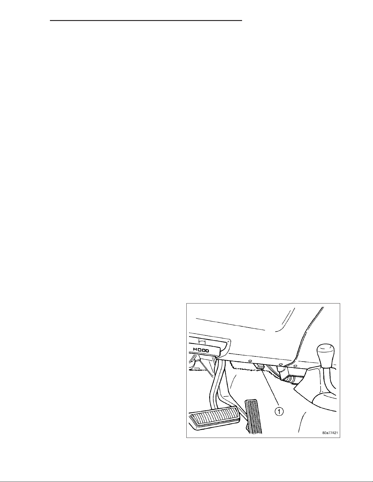
NOTE: Various diagnostic procedures may actually cause a diagnostic monitor to set a DTC. For instance,
pulling a spark plug wire to perform a spark test may set the misfire code. When a repair is completed and
verified, connect the DRB scan tool to the 16–way data link connector (1) to erase all DTC’s and extinguish
the MIL.
OPERATION - TASK MANAGER
The Task Manager determines which tests happen when and which functions occur when. Many of the diagnostic
steps required by OBD II must be performed under specific operating conditions. The Task Manager software organizes and prioritizes the diagnostic procedures. The job of the Task Manager is to determine if conditions are appropriate for tests to be run, monitor the parameters for a trip for each test, and record the results of the test. Following
are the responsibilities of the Task Manager software:
• Test Sequence
• MIL Illumination
• Diagnostic Trouble Codes (DTCs)
• Trip Indicator
• Freeze Frame Data Storage
• Similar Conditions Window
Test Sequence
In many instances, emissions systems must fail diagnostic tests more than once before the PCM illuminates the
MIL. These tests are know as ’two trip monitors.’ Other tests that turn the MIL lamp on after a single failure are
known as ’one trip monitors.’ A trip is defined as ’start the vehicle and operate it to meet the criteria necessary to
run the given monitor.’
Many of the diagnostic tests must be performed under certain operating conditions. However, there are times when
tests cannot be run because another test is in progress (conflict), another test has failed (pending) or the Task
Manager has set a fault that may cause a failure of the test (suspend).
• Pending
Under some situations the Task Manager will not run a monitor if the MIL is illuminated and a fault is stored
from another monitor. In these situations, the Task Manager postpones monitors pending resolution of the
original fault. The Task Manager does not run the test until the problem is remedied.
For example, when the MIL is illuminated for an Oxygen Sensor fault, the Task Manager does not run the
Catalyst Monitor until the Oxygen Sensor fault is remedied. Since the Catalyst Monitor is based on signals
from the Oxygen Sensor, running the test would produce inaccurate results.
• Conflict
There are situations when the Task Manager does not run a test if another monitor is in progress. In these
situations, the effects of another monitor running could result in an erroneous failure. If this conflict is present,
the monitor is not run until the conflicting condition passes. Most likely the monitor will run later after the conflicting monitor has passed.
For example, if the Fuel System Monitor is in progress, the Task Manager does not run the EGR Monitor.
Since both tests monitor changes in air/fuel ratio and adaptive fuel compensation, the monitors will conflict with
each other.
Page 7

DR/DH EMISSIONS CONTROL 25 - 7
• Suspend
Occasionally the Task Manager may not allow a two trip fault to mature. The Task Manager will suspend the
maturing of a fault if a condition exists that may induce an erroneous failure. This prevents illuminating the MIL
for the wrong fault and allows more precis diagnosis.
For example, if the PCM is storing a one trip fault for the Oxygen Sensor and the EGR monitor, the Task
Manager may still run the EGR Monitor but will suspend the results until the Oxygen Sensor Monitor either
passes or fails. At that point the Task Manager can determine if the EGR system is actually failing or if an
Oxygen Sensor is failing.
MIL Illumination
The PCM Task Manager carries out the illumination of the MIL. The Task Manager triggers MIL illumination upon
test failure, depending on monitor failure criteria.
The Task Manager Screen shows both a Requested MIL state and an Actual MIL state. When the MIL is illuminated
upon completion of a test for a third trip, the Requested MIL state changes to OFF. However, the MIL remains
illuminated until the next key cycle. (On some vehicles, the MIL will actually turn OFF during the third key cycle)
During the key cycle for the third good trip, the Requested MIL state is OFF, while the Actual MILL state is ON. After
the next key cycle, the MIL is not illuminated and both MIL states read OFF.
Diagnostic Trouble Codes (DTCs)
With OBD II, different DTC faults have different priorities according to regulations. As a result, the priorities determine MIL illumination and DTC erasure. DTCs are entered according to individual priority. DTCs with a higher priority overwrite lower priority DTCs.
Priorities
• Priority 0 —Non-emissions related trouble codes
• Priority 1 — One trip failure of a two trip fault for non-fuel system and non-misfire.
• Priority 2 — One trip failure of a two trip fault for fuel system (rich/lean) or misfire.
• Priority 3 — Two trip failure for a non-fuel system and non-misfire or matured one trip comprehensive com-
ponent fault.
• Priority 4 — Two trip failure or matured fault for fuel system (rich/lean) and misfire or one trip catalyst damaging misfire.
Non-emissions related failures have no priority. One trip failures of two trip faults have low priority. Two trip failures
or matured faults have higher priority. One and two trip failures of fuel system and misfire monitor take precedence
over non-fuel system and non-misfire failures.
DTC Self Erasure
With one trip components or systems, the MIL is illuminated upon test failure and DTCs are stored.
Two trip monitors are components requiring failure in two consecutive trips for MIL illumination. Upon failure of the
first test, the Task Manager enters a maturing code. If the component fails the test for a second time the code
matures and a DTC is set.
After three good trips the MIL is extinguished and the Task Manager automatically switches the trip counter to a
warm-up cycle counter. DTCs are automatically erased following 40 warm-up cycles if the component does not fail
again.
For misfire and fuel system monitors, the component must pass the test under a Similar Conditions Window in order
to record a good trip. A Similar Conditions Window is when engine RPM is within ±375 RPM and load is within
±10% of when the fault occurred.
NOTE: It is important to understand that a component does not have to fail under a similar window of operation to mature. It must pass the test under a Similar Conditions Window when it failed to record a Good
Trip for DTC erasure for misfire and fuel system monitors.
DTCs can be erased anytime with a DRB III. Erasing the DTC with the DRB III erases all OBD II information. The
DRB III automatically displays a warning that erasing the DTC will also erase all OBD II monitor data. This includes
all counter information for warm-up cycles, trips and Freeze Frame.
Page 8

25 - 8 EMISSIONS CONTROL DR/DH
Trip Indicator
The Trip is essential for running monitors and extinguishing the MIL. In OBD II terms, a trip is a set of vehicle
operating conditions that must be met for a specific monitor to run. All trips begin with a key cycle.
Good Trip
The Good Trip counters are as follows:
• Specific Good Trip
• Fuel System Good Trip
• Misfire Good Trip
• Alternate Good Trip (appears as a Global Good Trip on DRB III)
• Comprehensive Components
• Major Monitor
• Warm-Up Cycles
Specific Good Trip
The term Good Trip has different meanings depending on the circumstances:
• If the MIL is OFF, a trip is defined as when the Oxygen Sensor Monitor and the Catalyst Monitor have been
completed in the same drive cycle.
• If the MIL is ON and a DTC was set by the Fuel Monitor or Misfire Monitor (both continuous monitors), the
vehicle must be operated in the Similar Condition Window for a specified amount of time.
• If the MIL is ON and a DTC was set by a Task Manager commanded once-per-trip monitor (such as the Oxygen Sensor Monitor, Catalyst Monitor, Purge Flow Monitor, Leak Detection Pump Monitor, EGR Monitor or
Oxygen Sensor Heater Monitor), a good trip is when the monitor is passed on the next start-up.
• If the MIL is ON and any other emissions DTC was set (not an OBD II monitor), a good trip occurs when the
Oxygen Sensor Monitor and Catalyst Monitor have been completed, or two minutes of engine run time if the
Oxygen Sensor Monitor and Catalyst Monitor have been stopped from running.
Fuel System Good Trip
To count a good trip (three required) and turn off the MIL, the following conditions must occur:
• Engine in closed loop
• Operating in Similar Conditions Window
• Short Term multiplied by Long Term less than threshold
• Less than threshold for a predetermined time
If all of the previous criteria are met, the PCM will count a good trip (three required) and turn off the MIL.
Misfire Good Trip
If the following conditions are met the PCM will count one good trip (three required) in order to turn off the MIL:
• Operating in Similar Condition Window
• 1000 engine revolutions with no misfire
Warm-Up Cycles
Once the MIL has been extinguished by the Good Trip Counter, the PCM automatically switches to a Warm-Up
Cycle Counter that can be viewed on the DRB III. Warm-Up Cycles are used to erase DTCs and Freeze Frames.
Forty Warm-Up cycles must occur in order for the PCM to self-erase a DTC and Freeze Frame. A Warm-Up Cycle
is defined as follows:
• Engine coolant temperature must start below and rise above 160° F
• Engine coolant temperature must rise by 40° F
• No further faults occur
Freeze Frame Data Storage
Once a failure occurs, the Task Manager records several engine operating conditions and stores it in a Freeze
Frame. The Freeze Frame is considered one frame of information taken by an on-board data recorder. When a fault
occurs, the PCM stores the input data from various sensors so that technicians can determine under what vehicle
operating conditions the failure occurred.
The data stored in Freeze Frame is usually recorded when a system fails the first time for two trip faults. Freeze
Frame data will only be overwritten by a different fault with a higher priority.
Page 9

DR/DH EMISSIONS CONTROL 25 - 9
CAUTION: Erasing DTCs, either with the DRB III or by disconnecting the battery, also clears all Freeze
Frame data.
Similar Conditions Window
The Similar Conditions Window displays information about engine operation during a monitor. Absolute MAP (engine
load) and Engine RPM are stored in this window when a failure occurs. There are two different Similar conditions
Windows: Fuel System and Misfire.
FUEL SYSTEM
• Fuel System Similar Conditions Window — An indicator that ’Absolute MAP When Fuel Sys Fail’ and ’RPM
When Fuel Sys Failed’ are all in the same range when the failure occurred. Indicated by switching from ’NO’
to ’YES’.
• Absolute MAP When Fuel Sys Fail — The stored MAP reading at the time of failure. Informs the user at
what engine load the failure occurred.
• Absolute MAP — A live reading of engine load to aid the user in accessing the Similar Conditions Window.
• RPM When Fuel Sys Fail — The stored RPM reading at the time of failure. Informs the user at what engine
RPM the failure occurred.
• Engine RPM — A live reading of engine RPM to aid the user in accessing the Similar Conditions Window.
• Adaptive Memory Factor — The PCM utilizes both Short Term Compensation and Long Term Adaptive to
calculate the Adaptive Memory Factor for total fuel correction.
• Upstream O2S Volts — A live reading of the Oxygen Sensor to indicate its performance. For example, stuck
lean, stuck rich, etc.
• SCW Time in Window (Similar Conditions Window Time in Window) — A timer used by the PCM that
indicates that, after all Similar Conditions have been met, if there has been enough good engine running time
in the SCW without failure detected. This timer is used to increment a Good Trip.
• Fuel System Good Trip Counter — A Trip Counter used to turn OFF the MIL for Fuel System DTCs. To
increment a Fuel System Good Trip, the engine must be in the Similar Conditions Window, Adaptive Memory
Factor must be less than calibrated threshold and the Adaptive Memory Factor must stay below that threshold
for a calibrated amount of time.
• Test Done This Trip — Indicates that the monitor has already been run and completed during the current trip.
MISFIRE
• Same Misfire Warm-Up State — Indicates if the misfire occurred when the engine was warmed up (above
160° F).
• In Similar Misfire Window — An indicator that ’Absolute MAP When Misfire Occurred’ and ’RPM When Mis-
fire Occurred’ are all in the same range when the failure occurred. Indicated by switching from ’NO’ to ’YES’.
• Absolute MAP When Misfire Occurred — The stored MAP reading at the time of failure. Informs the user at
what engine load the failure occurred.
• Absolute MAP — A live reading of engine load to aid the user in accessing the Similar Conditions Window.
• RPM When Misfire Occurred — The stored RPM reading at the time of failure. Informs the user at what
engine RPM the failure occurred.
• Engine RPM — A live reading of engine RPM to aid the user in accessing the Similar Conditions Window.
• Adaptive Memory Factor — The PCM utilizes both Short Term Compensation and Long Term Adaptive to
calculate the Adaptive Memory Factor for total fuel correction.
• 200 Rev Counter — Counts 0–100 720 degree cycles.
• SCW Cat 200 Rev Counter — Counts when in similar conditions.
• SCW FTP 1000 Rev Counter — Counts 0–4 when in similar conditions.
• Misfire Good Trip Counter — Counts up to three to turn OFF the MIL.
• Misfire Data— Data collected during test.
• Test Done This Trip— Indicates YES when the test is done.
Page 10

25 - 10 EMISSIONS CONTROL DR/DH
OPERATION - NON-MONITORED CIRCUITS
The PCM does not monitor the following circuits, systems and conditions that could have malfunctions causing
driveability problems. The PCM might not store diagnostic trouble codes for these conditions. However, problems
with these systems may cause the PCM to store diagnostic trouble codes for other systems or components. EXAM-
PLE: a fuel pressure problem will not register a fault directly, but could cause a rich/lean condition or misfire. This
could cause the PCM to store an oxygen sensor or misfire diagnostic trouble code
FUEL PRESSURE
The fuel pressure regulator controls fuel system pressure. The PCM cannot detect a clogged fuel pump inlet filter,
clogged in-line fuel filter, or a pinched fuel supply or return line. However, these could result in a rich or lean condition causing the PCM to store an oxygen sensor or fuel system diagnostic trouble code.
SECONDARY IGNITION CIRCUIT
The PCM cannot detect an inoperative ignition coil, fouled or worn spark plugs, ignition cross firing, or open spark
plug cables.
CYLINDER COMPRESSION
The PCM cannot detect uneven, low, or high engine cylinder compression.
EXHAUST SYSTEM
The PCM cannot detect a plugged, restricted or leaking exhaust system, although it may set a fuel system fault.
FUEL INJECTOR MECHANICAL MALFUNCTIONS
The PCM cannot determine if a fuel injector is clogged, the needle is sticking or if the wrong injector is installed.
However, these could result in a rich or lean condition causing the PCM to store a diagnostic trouble code for either
misfire, an oxygen sensor, or the fuel system.
EXCESSIVE OIL CONSUMPTION
Although the PCM monitors engine exhaust oxygen content when the system is in closed loop, it cannot determine
excessive oil consumption.
THROTTLE BODY AIR FLOW
The PCM cannot detect a clogged or restricted air cleaner inlet or filter element.
VACUUM ASSIST
The PCM cannot detect leaks or restrictions in the vacuum circuits of vacuum assisted engine control system
devices. However, these could cause the PCM to store a MAP sensor diagnostic trouble code and cause a high idle
condition.
PCM SYSTEM GROUND
The PCM cannot determine a poor system ground. However, one or more diagnostic trouble codes may be generated as a result of this condition. The module should be mounted to the body at all times, also during diagnostic.
PCM CONNECTOR ENGAGEMENT
The PCM may not be able to determine spread or damaged connector pins. However, it might store diagnostic
trouble codes as a result of spread connector pins.
Page 11

DR/DH EVAPORATIVE EMISSIONS 25 - 11
EVAPORATIVE EMISSIONS
TABLE OF CONTENTS
page page
EVAPORATIVE EMISSIONS
DESCRIPTION - EVAP SYSTEM ............11
SPECIFICATIONS
TORQUE - EVAP SYSTEM ...............12
SOLENOID - EVAP/PURGE
DESCRIPTION .........................12
OPERATION ...........................12
REMOVAL .............................12
INSTALLATION .........................13
CAP - FUEL FILLER
DESCRIPTION .........................13
OPERATION ...........................13
REMOVAL
REMOVAL/INSTALLATION ...............13
PUMP - LEAK DETECTION
DESCRIPTION .........................13
OPERATION ...........................14
REMOVAL .............................17
INSTALLATION .........................18
ORVR
DESCRIPTION .........................18
EVAPORATIVE EMISSIONS
OPERATION ...........................18
PUMP-NATURAL VAC LEAK DETECTION
DESCRIPTION .........................19
OPERATION ...........................19
REMOVAL .............................20
INSTALLATION .........................23
VALVE - PCV
DESCRIPTION .........................27
OPERATION ...........................29
DIAGNOSIS AND TESTING
PCV VALVE - 3.7L V-6/ 4.7L V-8 ...........30
REMOVAL .............................32
INSTALLATION .........................33
LINES - VACUUM
DESCRIPTION .........................33
CANISTER - VAPOR
DESCRIPTION .........................34
OPERATION ...........................35
REMOVAL .............................36
INSTALLATION .........................41
DESCRIPTION - EVAP SYSTEM
The evaporation control system prevents the emission of fuel tank vapors into the atmosphere. When fuel evaporates in the fuel tank, the vapors pass through vent hoses or tubes into the two charcoal filled evaporative canisters.
The canisters temporarily hold the vapors. The Powertrain Control Module (PCM) allows intake manifold vacuum to
draw vapors into the combustion chambers during certain operating conditions.
All gasoline powered engines use a duty cycle purge system. The PCM controls vapor flow by operating the duty
cycle EVAP purge solenoid. Refer to Duty Cycle EVAP Canister Purge Solenoid for additional information.
When equipped with certain emissions packages, a Leak Detection Pump (LDP) will be used as part of the evaporative system. This pump is used as a part of OBD II requirements. Refer to Leak Detection Pump for additional
information. Other emissions packages will use a Natural Vacuum Leak Detection (NVLD) system in place of the
LDP. Refer to NVLD for additional information.
NOTE: The hoses used in this system are specially manufactured. If replacement becomes necessary, it is
important to use only fuel resistant hose.
Page 12

25 - 12 EVAPORATIVE EMISSIONS DR/DH
SPECIFICATIONS
TORQUE - EVAP SYSTEM
DESCRIPTION N·m Ft. Lbs. In. Lbs.
EVAP Canister Mounting
Nuts
EVAP Canister Mounting
Bracket-to-Frame Bolts
Leak Detection Pump
Mounting Bolts
Leak Detection Pump
Filter Mounting Bolt
11 -
14 10
11 - 95
11 - 95
95
125
SOLENOID - EVAP/PURGE
DESCRIPTION
The duty cycle EVAP canister purge solenoid is located in the engine compartment. It is attached to the side of the
Power Distribution Center (PDC).
OPERATION
The Powertrain Control Module (PCM) operates the solenoid.
During the cold start warm-up period and the hot start time delay, the PCM does not energize the solenoid. When
de-energized, no vapors are purged. The PCM de-energizes the solenoid during open loop operation.
The engine enters closed loop operation after it reaches a specified temperature and the time delay ends. During
closed loop operation, the PCM energizes and de-energizes the solenoid 5 or 10 times per second, depending upon
operating conditions. The PCM varies the vapor flow rate by changing solenoid pulse width. Pulse width is the
amount of time the solenoid energizes. The PCM adjusts solenoid pulse width based on engine operating condition.
REMOVAL
The duty cycle EVAP canister purge solenoid (3) is
located in the engine compartment. It is attached to
the side of the Power Distribution Center (PDC).
1. Disconnect electrical wiring connector at solenoid.
2. Disconnect vacuum harness (2) at solenoid.
3. Remove solenoid from mounting bracket.
Page 13

DR/DH EVAPORATIVE EMISSIONS 25 - 13
INSTALLATION
1. Install solenoid assembly to mounting bracket.
2. Connect vacuum harness.
3. Connect electrical connector.
CAP - FUEL FILLER
DESCRIPTION
The plastic fuel tank filler tube cap is threaded onto the end of the fuel fill tube. Certain models are equipped with
a 1/4 turn cap.
OPERATION
The loss of any fuel or vapor out of fuel filler tube is prevented by the use of a pressure-vacuum fuel fill cap. Relief
valves inside the cap will release fuel tank pressure at predetermined pressures. Fuel tank vacuum will also be
released at predetermined values. This cap must be replaced by a similar unit if replacement is necessary. This is
in order for the system to remain effective.
CAUTION: Remove fill cap before servicing any fuel system component to relieve tank pressure. If equipped
with a Leak Detection Pump (LDP), or NVLD system, the cap must be tightened securely. If cap is left loose,
a Diagnostic Trouble Code (DTC) may be set.
REMOVAL
REMOVAL/INSTALLATION
If replacement of the 1/4 turn fuel tank filler tube cap is necessary, it must be replaced with an identical cap to be
sure of correct system operation.
CAUTION: Remove the fuel tank filler tube cap to relieve fuel tank pressure. The cap must be removed prior
to disconnecting any fuel system component or before draining the fuel tank.
PUMP - LEAK DETECTION
DESCRIPTION
Vehicles equipped with JTEC engine control modules use a leak detection pump. Vehicles equipped with NGC
engine control modules use an NVLD pump. Refer to Natural Vacuum - Leak Detection (NVLD) for additional information.
The evaporative emission system is designed to prevent the escape of fuel vapors from the fuel system. Leaks in
the system, even small ones, can allow fuel vapors to escape into the atmosphere. Government regulations require
onboard testing to make sure that the evaporative (EVAP) system is functioning properly. The leak detection system
tests for EVAP system leaks and blockage. It also performs self-diagnostics. During self-diagnostics, the Powertrain
Control Module (PCM) first checks the Leak Detection Pump (LDP) for electrical and mechanical faults. If the first
checks pass, the PCM then uses the LDP to seal the vent valve and pump air into the system to pressurize it. If a
leak is present, the PCM will continue pumping the LDP to replace the air that leaks out. The PCM determines the
size of the leak based on how fast/long it must pump the LDP as it tries to maintain pressure in the system.
Page 14
25 - 14 EVAPORATIVE EMISSIONS DR/DH
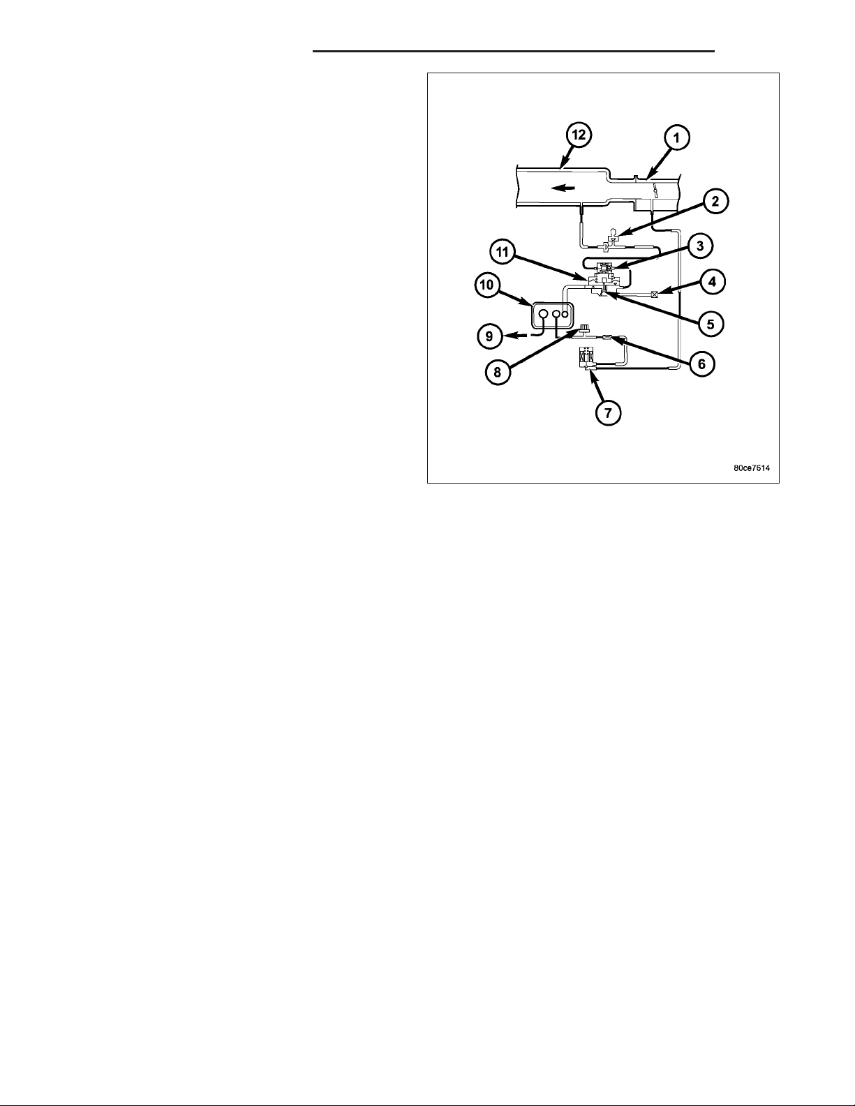
EVAP LEAK DETECTION SYSTEM
COMPONENTS
Service Port: Used with special tools like the Miller
Evaporative Emissions Leak Detector (EELD) to test
for leaks in the system.
EVAP Purge Solenoid: The PCM uses the EVAP
purge solenoid to control purging of excess fuel
vapors stored in the EVAP canister. It remains closed
during leak testing to prevent loss of pressure.
EVAP Canister: The EVAP canister stores fuel vapors
from the fuel tank for purging.
EVAP Purge Orifice: Limits purge volume.
EVAP System Air Filter: Provides air to the LDP for
pressurizing the system. It filters out dirt while allowing
a vent to atmosphere for the EVAP system.
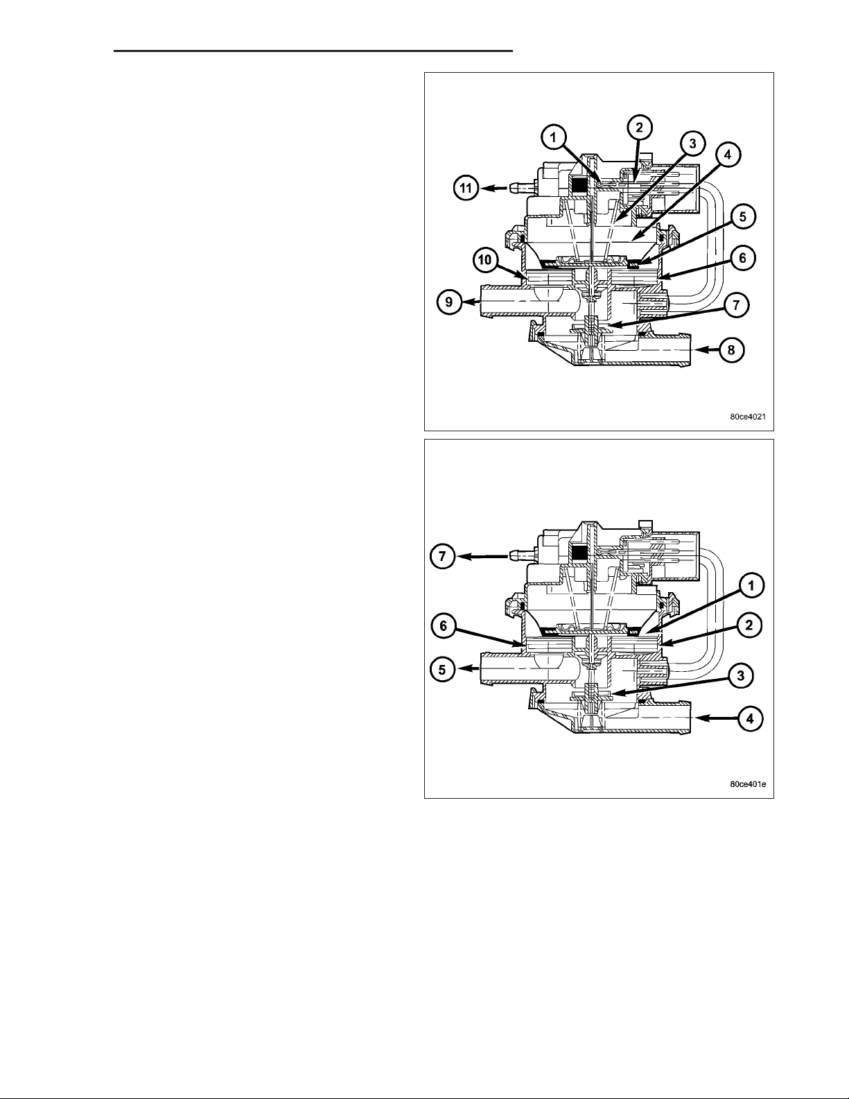
OPERATION
The main purpose of the LDP is to pressurize the fuel system for leak checking. It closes the EVAP system vent to
atmospheric pressure so the system can be pressurized for leak testing. The diaphragm is powered by engine vacuum. It pumps air into the EVAP system to develop a pressure of about 7.59 H2O (1/4) psi. A reed switch in the LDP
allows the PCM to monitor the position of the LDP diaphragm. The PCM uses the reed switch input to monitor how
fast the LDP is pumping air into the EVAP system. This allows detection of leaks and blockage. The LDP assembly
consists of several parts. The solenoid is controlled by the PCM, and it connects the upper pump cavity to either
engine vacuum or atmospheric pressure. A vent valve closes the EVAP system to atmosphere, sealing the system
during leak testing. The pump section of the LDP consists of a diaphragm that moves up and down to bring air in
through the air filter and inlet check valve, and pump it out through an outlet check valve into the EVAP system. The
diaphragm is pulled up by engine vacuum, and pushed down by spring pressure, as the LDP solenoid turns on and
off. The LDP also has a magnetic reed switch to signal diaphragm position to the PCM. When the diaphragm is
down, the switch is closed, which sends a 12 V (system voltage) signal to the PCM. When the diaphragm is up, the
switch is open, and there is no voltage sent to the PCM. This allows the PCM to monitor LDP pumping action as it
turns the LDP solenoid on and off.
Page 15
DR/DH EVAPORATIVE EMISSIONS 25 - 15
LDP AT REST (NOT POWERED)
When the LDP is at rest (no electrical/vacuum) the
diaphragm is allowed to drop down if the internal
(EVAP system) pressure is not greater than the return
spring. The LDP solenoid blocks the engine vacuum
port and opens the atmospheric pressure port connected through the EVAP system air filter. The vent
valve is held open by the diaphragm. This allows the
canister to see atmospheric pressure.
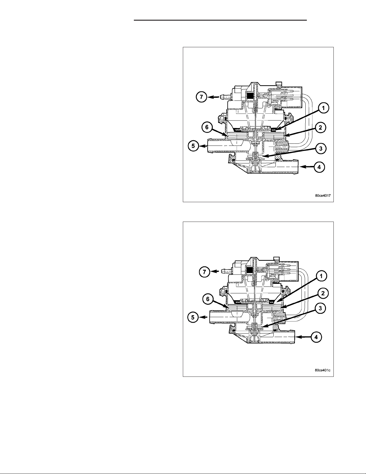
DIAPHRAGM UPWARD MOVEMENT
When the PCM energizes the LDP solenoid, the solenoid blocks the atmospheric port leading through the
EVAP air filter and at the same time opens the engine
vacuum port to the pump cavity above the diaphragm.
The diaphragm moves upward when vacuum above
the diaphragm exceeds spring force. This upward
movement closes the vent valve. It also causes low
pressure below the diaphragm, unseating the inlet
check valve and allowing air in from the EVAP air filter. When the diaphragm completes its upward movement, the LDP reed switch turns from closed to open.
Page 16
25 - 16 EVAPORATIVE EMISSIONS DR/DH
DIAPHRAGM DOWNWARD MOVEMENT
Based on reed switch input, the PCM de-energizes
the LDP solenoid, causing it to block the vacuum port,
and open the atmospheric port. This connects the
upper pump cavity to atmosphere through the EVAP
air filter. The spring is now able to push the diaphragm
down. The downward movement of the diaphragm
closes the inlet check valve and opens the outlet
check valve pumping air into the evaporative system.
The LDP reed switch turns from open to closed, allowing the PCM to monitor LDP pumping (diaphragm
up/down) activity. During the pumping mode, the diaphragm will not move down far enough to open the
vent valve. The pumping cycle is repeated as the solenoid is turned on and off. When the evaporative system begins to pressurize, the pressure on the bottom
of the diaphragm will begin to oppose the spring pressure, slowing the pumping action. The PCM watches
the time from when the solenoid is de-energized, until
the diaphragm drops down far enough for the reed
switch to change from opened to closed. If the reed
switch changes too quickly, a leak may be indicated.
The longer it takes the reed switch to change state,
the tighter the evaporative system is sealed. If the
system pressurizes too quickly, a restriction somewhere in the EVAP system may be indicated.
PUMPING ACTION
Action : During portions of this test, the PCM uses the
reed switch to monitor diaphragm movement. The
solenoid is only turned on by the PCM after the reed
switch changes from open to closed, indicating that
the diaphragm has moved down. At other times during
the test, the PCM will rapidly cycle the LDP solenoid
on and off to quickly pressurize the system. During
rapid cycling, the diaphragm will not move enough to
change the reed switch state. In the state of rapid
cycling, the PCM will use a fixed time interval to cycle
the solenoid. If the system does not pass the EVAP
Leak Detection Test, the following DTCs may be set:
• P0442 - EVAP LEAK MONITOR 0.0409 LEAK
DETECTED
• P0455 - EVAP LEAK MONITOR LARGE LEAK
DETECTED
• P0456 - EVAP LEAK MONITOR 0.0209 LEAK
DETECTED
• P1486 - EVAP LEAK MON PINCHED HOSE
FOUND
• P1494 - LEAK DETECTION PUMP SW OR MECH FAULT
• P1495 - LEAK DETECTION PUMP SOLENOID CIRCUIT
Page 17

DR/DH EVAPORATIVE EMISSIONS 25 - 17
REMOVAL
The Leak Detection Pump (LDP) (4) and LDP filter are attached to the front of the EVAP canister mounting bracket.
This is located near the front of the fuel tank. The LDP and LDP filter are replaced (serviced) as one unit.
1. Raise and support vehicle.
2. Certain models, equipped with a certain fuel tank size, may require the removal of the fuel tank skid plate and/or
the transfer case skid plate to gain access to the leak pump. Remove necessary skid plates.
3. Carefully remove hose at LDP filter.
4. Remove LDP filter mounting bolt and remove from vehicle.
5. Carefully remove vapor/vacuum lines at LDP.
6. Disconnect electrical connector at LDP.
7. Remove LDP mounting bolt and remove LDP from vehicle.
Page 18

25 - 18 EVAPORATIVE EMISSIONS DR/DH
INSTALLATION
The LDP (4) and LDP filter are attached to the front of the EVAP canister mounting bracket. The LDP and LDP filter
are replaced (serviced) as one unit.
1. Install LDP to mounting bracket. Refer to Torque Specifications.
2. Install LDP filter to mounting bracket. Refer to Torque Specifications.
3. Carefully install vapor/vacuum lines to LDP, and install hose to LDP filter. The vapor/vacuum lines and hoses
must be firmly connected. Check the vapor/vacuum lines at the LDP, LDP filter and EVAP canister purge
solenoid for damage or leaks. If a leak is present, a Diagnostic Trouble Code (DTC) may be set.
4. Connect electrical connector to LDP.
5. If necessary, install skid plate(s).
ORVR
DESCRIPTION
The ORVR (On-Board Refueling Vapor Recovery) system consists of a unique fuel tank, flow management valve,
fluid control valve, one-way check valve and vapor canister.
OPERATION
The ORVR (On-Board Refueling Vapor Recovery) system is used to remove excess fuel tank vapors. This is done
while the vehicle is being refueled.
Fuel flowing into the fuel filler tube (approx. 1” I.D.) creates an aspiration effect drawing air into the fuel fill tube.
During refueling, the fuel tank is vented to the EVAP canister to capture escaping vapors. With air flowing into the
filler tube, there are no fuel vapors escaping to the atmosphere. Once the refueling vapors are captured by the
EVAP canister, the vehicle’s computer controlled purge system draws vapor out of the canister for the engine to
burn. The vapor flow is metered by the purge solenoid so that there is no, or minimal impact on driveability or
tailpipe emissions.
Page 19

DR/DH EVAPORATIVE EMISSIONS 25 - 19
As fuel starts to flow through the fuel fill tube, it opens the normally closed check valve and enters the fuel tank.
Vapor or air is expelled from the tank through the control valve and on to the vapor canister. Vapor is absorbed in
the EVAP canister until vapor flow in the lines stops. This stoppage occurs following fuel shut-off, or by having the
fuel level in the tank rise high enough to close the control valve. This control valve contains a float that rises to seal
the large diameter vent path to the EVAP canister. At this point in the refueling process, fuel tank pressure
increases, the check valve closes (preventing liquid fuel from spiting back at the operator), and fuel then rises up
the fuel filler tube to shut off the dispensing nozzle.
PUMP-NATURAL VAC LEAK DETECTION
DESCRIPTION
Vehicles equipped with an NGC Powertrain Control Module (PCM) use a Natural Vacuum Leak Detection (NVLD)
pump and system. Vehicles equipped with a JTEC PCM use an LDP (Leak Detection Pump). Refer to Leak Detection Pump (LDP) for additional information.
The NVLD pump is located in the same area as the leak detection pump. Refer to NVLD Removal / Installation for
additional information.
OPERATION
The Natural Vacuum Leak Detection (NVLD) system is the next generation evaporative leak detection system that
will first be used on vehicles equipped with the Next Generation Controller (NGC). This new system replaces the
leak detection pump as the method of evaporative system leak detection. This is to detect a leak equivalent to a
0.0209 (0.5 mm) hole. This system has the capability to detect holes of this size very dependably.
The basic leak detection theory employed with NVLD is the 9Gas Law9. This is to say that the pressure in a sealed
vessel will change if the temperature of the gas in the vessel changes. The vessel will only see this effect if it is
indeed sealed. Even small leaks will allow the pressure in the vessel to come to equilibrium with the ambient pressure. In addition to the detection of very small leaks, this system has the capability of detecting medium as well as
large evaporative system leaks.
A vent valve seals the canister vent during engine off conditions. If the vapor system has a leak of less than the
failure threshold, the evaporative system will be pulled into a vacuum, either due to the cool down from operating
temperature or diurnal ambient temperature cycling. The diurnal effect is considered one of the primary contributors
to the leak determination by this diagnostic. When the vacuum in the system exceeds about 19 H2O (0.25 KPA), a
vacuum switch closes. The switch closure sends a signal to the NGC. The NGC, via appropriate logic strategies,
utilizes the switch signal, or lack thereof, to make a determination of whether a leak is present.
The NVLD device is designed with a normally open vacuum switch, a normally closed solenoid, and a seal, which
is actuated by both the solenoid and a diaphragm. The NVLD is located on the atmospheric vent side of the canister. The NVLD assembly may be mounted on top of the canister outlet, or in-line between the canister and atmospheric vent filter. The normally open vacuum switch will close with about 19 H2O (0.25 KPA) vacuum in the
evaporative system. The diaphragm actuates the switch. This is above the opening point of the fuel inlet check valve
in the fill tube so cap off leaks can be detected. Submerged fill systems must have recirculation lines that do not
have the in-line normally closed check valve that protects the system from failed nozzle liquid ingestion, in order to
detect cap off conditions.
The normally closed valve in the NVLD is intended to maintain the seal on the evaporative system during the engine
off condition. If vacuum in the evaporative system exceeds 39 to 69 H2O (0.75 to 1.5 KPA), the valve will be pulled
off the seat, opening the seal. This will protect the system from excessive vacuum as well as allowing sufficient
purge flow in the event that the solenoid was to become inoperative.
The solenoid actuates the valve to unseal the canister vent while the engine is running. It also will be used to close
the vent during the medium and large leak tests and during the purge flow check. This solenoid requires an initial
1.5 amps of current to pull the valve open, but after 100 mili-seconds, will be duty cycled down to an average of
about 150 mA for the remainder of the drive cycle.
Another feature in the device is a diaphragm that will open the seal in the NVLD with pressure in the evaporative
system. The device will 9blow off9 at about 0.59 H2O (0.12 KPA) pressure to permit the venting of vapors during
refueling. An added benefit to this is that it will also allow the tank to 9breathe9 during increasing temperatures, thus
limiting the pressure in the tank to this low level. This is beneficial because the induced vacuum during a subsequent declining temperature will achieve the switch closed (pass threshold) sooner than if the tank had to decay
from a built up pressure.
Page 20

25 - 20 EVAPORATIVE EMISSIONS DR/DH
The device itself has 3 wires: Switch sense, solenoid driver and ground. It also includes a resistor to protect the
switch from a short to battery or a short to ground. The NGC utilizes a high-side driver to energize and duty-cycle
the solenoid.
REMOVAL
If Equipped With Horizontally Mounted EVAP Canisters
Page 21

DR/DH EVAPORATIVE EMISSIONS 25 - 21
The NVLD pump (4) is attached to the EVAP canister.
1. Raise and support vehicle.
2. Certain models, equipped with a certain fuel tank size, may require the removal of the fuel tank skid plate and/or
the transfer case skid plate to gain access to the leak pump. Remove necessary skid plates.
3. Disconnect electrical connector at NVLD assembly.
4. Carefully disconnect vapor lines from NVLD assembly.
5. Lift tab on NVLD assembly and twist assembly
counterclockwise.
6. Pull NVLD pump out to remove from EVAP
canister.
Page 22

25 - 22 EVAPORATIVE EMISSIONS DR/DH
7. Remove o-ring from EVAP canister.
If Equipped With Vertically Mounted EVAP Canisters
The NVLD pump (4) is located at the front of fuel tank.
1. Raise and support vehicle.
2. Certain models, equipped with a certain fuel tank size, may require the removal of the fuel tank skid plate and/or
the transfer case skid plate to gain access to the leak pump. Remove necessary skid plates.
3. Disconnect electrical connector at pump.
4. Carefully remove vapor/vacuum hoses at pump.
Page 23

DR/DH EVAPORATIVE EMISSIONS 25 - 23
5. The NVLD pump snaps into the EVAP canister.
Press on release tab (2) while rotating pump from
canister.
INSTALLATION
If Equipped With Horizontally Mounted EVAP Canisters
Page 24

25 - 24 EVAPORATIVE EMISSIONS DR/DH
The NVLD pump (4) is attached to the EVAP canister.
1. Install new o-ring to EVAP canister.
Page 25

DR/DH EVAPORATIVE EMISSIONS 25 - 25
2. Align NVLD assembly into EVAP canister.
3. Rotate NVLD assembly until alignment tab drops
into slot.
4. Connect electrical connector to NVLD assembly.
5. Carefully install vapor/vacuum lines to NVLD pump.
The vapor/vacuum lines and hoses must be
firmly connected. Check the vapor/vacuum
lines at the NVLD pump, filter and EVAP canister purge solenoid for damage or leaks. If a leak
is present, a Diagnostic Trouble Code (DTC)
may be set.
6. If necessary, install skid plate(s).
Page 26

25 - 26 EVAPORATIVE EMISSIONS DR/DH
If Equipped With Vertically Mounted EVAP Canisters
The NVLD pump (4) is located at the front of fuel tank.
1. Snap NVLD pump (1) to EVAP canister until tab (2)
engages.
2. Connect electrical connector to NVLD pump.
3. Carefully install vapor/vacuum lines to NVLD pump.
The vapor/vacuum lines and hoses must be
firmly connected. Check the vapor/vacuum
lines at the NVLD pump, filter and EVAP canister purge solenoid for damage or leaks. If a leak
is present, a Diagnostic Trouble Code (DTC)
may be set.
4. If equipped, install skid plate(s).
Page 27

DR/DH EVAPORATIVE EMISSIONS 25 - 27
VALVE - PCV
DESCRIPTION
3.7L V-6 / 4.7L V-8
The 3.7L V-6 and 4.7L V-8 engines are equipped with
a closed crankcase ventilation system and a Positive
Crankcase Ventilation (PCV) valve (6).
This system consists of:
• a PCV valve mounted to the oil filler housing.
The PCV valve is sealed to the oil filler housing
with an o-ring.
• the air cleaner housing
• two interconnected breathers (2) threaded into
the rear of each cylinder head.
• tubes and hoses to connect the system
components.
Page 28

25 - 28 EVAPORATIVE EMISSIONS DR/DH
5.7L V-8
The 5.7L V-8 engine is equipped with a closed crankcase ventilation system and a Positive Crankcase
Ventilation (PCV) valve (4).
This system consists of:
• a PCV valve mounted into the top of the intake
manifold, located to the right / rear of the throttle
body. The PCV valve (1) is sealed to the intake
manifold with 2 o-rings (2).
• passages in the intake manifold.
• tubes and hoses to connect the system
components.
Page 29

DR/DH EVAPORATIVE EMISSIONS 25 - 29
OPERATION
A typical enclosed crankcase ventilation system is
shown in the graphic.
The PCV system operates by engine intake manifold
vacuum. Filtered air is routed into the crankcase
through the air cleaner hose. The metered air, along
with crankcase vapors, are drawn through the PCV
valve (4) and into a passage in the intake manifold.
The PCV system manages crankcase pressure and
meters blow by gases to the intake system, reducing
engine sludge formation.
The PCV valve contains a spring loaded plunger. This
plunger meters the amount of crankcase vapors
routed into the combustion chamber based on intake
manifold vacuum.
When the engine is not operating or during an engine
pop-back, the spring forces the plunger back against
the seat. This will prevent vapors from flowing through
the valve.
During periods of high manifold vacuum, such as idle
or cruising speeds, vacuum is sufficient to completely
compress spring. It will then pull the plunger to the top
of the valve. In this position there is minimal vapor
flow through the valve.
Page 30

25 - 30 EVAPORATIVE EMISSIONS DR/DH
During periods of moderate manifold vacuum, the
plunger is only pulled part way back from inlet. This
results in maximum vapor flow through the valve.
DIAGNOSIS AND TESTING
PCV VALVE - 3.7L V-6/ 4.7L V-8
1. Disconnect PCV line/hose (5) by disconnecting rubber connecting hose at PCV valve fitting.
2. Remove PCV valve at oil filler tube by rotating PCV
valve downward until locating tabs (2) have been
freed at cam lock (3). After tabs have cleared, pull
valve straight out from filler tube. To prevent dam-
age to PCV valve locating tabs, valve must be
pointed downward for removal. Do not force
valve from oil filler tube.
3. After valve is removed, check condition of valve
o-ring (1). Also, PCV valve should rattle when
shaken.
4. Reconnect PCV valve to its connecting line/hose.
5. Start engine and bring to idle speed.
6. If valve is not plugged, a hissing noise will be
heard as air passes through valve. Also, a strong
vacuum should be felt with a finger placed at valve
inlet.
7. If vacuum is not felt at valve inlet, check line/hose
for kinks or for obstruction. If necessary, clean out
intake manifold fitting at rear of manifold. Do this
by turning a 1/4 inch drill (by hand) through the fitting to dislodge any solid particles. Blow out the fitting with
shop air. If necessary, use a smaller drill to avoid removing any metal from the fitting.
8. Do not attempt to clean the old PCV valve.
9. Return PCV valve back to oil filler tube by placing valve locating tabs (2) into cam lock (3). Press PCV valve in
and rotate valve upward. A slight click will be felt when tabs have engaged cam lock. Valve should be pointed
towards rear of vehicle.
10. Connect PCV line/hose (5) and connecting rubber hose to PCV valve.
11. Disconnect rubber hose from fresh air fitting at air cleaner resonator box. Start engine and bring to idle speed.
Hold a piece of stiff paper (such as a parts tag) loosely over the opening of the disconnected rubber hose.
12. The paper should be drawn against the hose opening with noticeable force. This will be after allowing approx-
imately one minute for crankcase pressure to reduce.
Page 31

DR/DH EVAPORATIVE EMISSIONS 25 - 31
13. If vacuum is not present, disconnect each PCV
system hose at top of each crankcase breather
(1). Check for obstructions or restrictions.
14. If vacuum is still not present, remove each PCV
system crankcase breather (1) from each cylinder
head. Check for obstructions or restrictions. If
plugged, replace breather. Tighten breather to 12
N·m (106 in. lbs.) torque. Do not attempt to clean
breather.
15. If vacuum is still not present, disconnect each
PCV system hose (1) at each fitting, and at each
check valve (2). Check for obstructions or
restrictions.
Page 32

25 - 32 EVAPORATIVE EMISSIONS DR/DH
REMOVAL
3.7L V-6 / 4.7L V-8
The PCV valve (6) is located on the oil filler tube (4).
Two locating tabs are located on the side of the valve
(2). These 2 tabs fit into a cam lock (3) in the oil filler
tube. An o-ring (1) seals the valve to the filler tube.
1. Disconnect PCV line/hose (5) by disconnecting rubber hose at PCV valve fitting.
2. Remove PCV valve at oil filler tube by rotating PCV
valve downward (counter-clockwise) until locating
tabs (2) have been freed at cam lock (3). After tabs
have cleared, pull valve straight out from filler tube.
To prevent damage to PCV valve locating tabs,
valve must be pointed downward for removal.
Do not force valve from oil filler tube.
3. After valve is removed, check condition of valve
o-ring (1).
5.7L V-8
The PCV valve (4) is mounted into the top of the
intake manifold (1). This is located to the right / rear of
the throttle body (2).
Page 33

DR/DH EVAPORATIVE EMISSIONS 25 - 33
1. The PCV valve is sealed to the intake manifold
with 2 O-rings (2).
2. Remove PCV valve by rotating counter-clockwise
90 degrees until locating tabs (3) have been freed.
After tabs have cleared, pull valve straight up from
intake manifold.
3. After valve is removed, check condition of 2 valve
O-rings (2).
INSTALLATION
3.7L V6 / 4.7L V-8
The PCV valve is located on the oil filler tube. Two locating tabs are located on the side of the valve. These 2 tabs
fit into a cam lock in the oil filler tube. An o-ring seals the valve to the filler tube.
1. Return PCV valve back to oil filler tube by placing valve locating tabs into cam lock. Press PCV valve in and
rotate valve upward. A slight click will be felt when tabs have engaged cam lock. Valve should be pointed
towards rear of vehicle.
2. Connect PCV line/hose and rubber hose to PCV valve.
5.7L V-8
1. Clean out intake manifold opening.
2. Check condition of 2 o-rings on PCV valve.
3. Apply engine oil to 2 o-rings.
4. Place PCV valve into intake manifold and rotate 90 degrees clockwise for installation.
LINES - VACUUM
DESCRIPTION
A vacuum schematic for emission related items can be found on the vehicles VECI label. Refer to Vehicle Emission
Control Information (VECI) Label for label location.
Page 34

25 - 34 EVAPORATIVE EMISSIONS DR/DH
CANISTER - VAPOR
DESCRIPTION
Page 35

DR/DH EVAPORATIVE EMISSIONS 25 - 35
Two EVAP canisters are used. Depending on vehicle model and fuel tank size, the canisters may be mounted either
vertically or horizontally. These maintenance free, EVAP canisters (5) are located near the front of the fuel tank.
OPERATION
Two EVAP canisters are used. Depending on vehicle model and fuel tank size, the canisters may be mounted either
vertically or horizontally.
Page 36

25 - 36 EVAPORATIVE EMISSIONS DR/DH
The EVAP canisters are filled with granules of an activated carbon mixture. Fuel vapors entering the EVAP canisters
are absorbed by the charcoal granules.
Fuel tank pressure vents into the EVAP canisters. Fuel vapors are temporarily held in the canisters until they can be
drawn into the intake manifold. The duty cycle EVAP canister purge solenoid allows the EVAP canisters to be
purged at predetermined times and at certain engine operating conditions.
REMOVAL
Page 37

DR/DH EVAPORATIVE EMISSIONS 25 - 37
Two EVAP canisters are used. Depending on vehicle model and fuel tank size, the canisters may be mounted either
vertically or horizontally. These maintenance free, EVAP canisters (5) are located near the front of the fuel tank.
Page 38

25 - 38 EVAPORATIVE EMISSIONS DR/DH
Type 1 Canisters
Use the following procedure for vertically mounted canisters.
1 - CANISTER MOUNTING NUTS
2 - CONNECTING HOSE
3 - UPPER SUPPORT BRACKET
4 - LOWER SUPPORT BRACKET
5 - OUTER CANISTER
6 - INNER CANISTER
1. Raise and support vehicle.
2. Certain models, equipped with a certain fuel tank size, may require the removal of the fuel tank skid plate and/or
the transfer case skid plate to gain access to the EVAP canister(s). Remove necessary skid plates.
3. Remove fuel tubes/lines at each EVAP canister. Note location of tubes/lines before removal for easier installation.
4. Remove lower support bracket (4).
5. Remove mounting nuts (1) at top of each canister.
6. Remove each canister from upper support bracket.
Type 2 Canisters
Use the following procedure for horizontally mounted canisters.
1. Raise and support vehicle.
2. Certain models, equipped with a certain fuel tank size, may require the removal of the fuel tank skid plate and/or
the transfer case skid plate to gain access to the EVAP canister(s). Remove necessary skid plates.
Page 39

DR/DH EVAPORATIVE EMISSIONS 25 - 39
3. Remove fuel tubes/lines (1) at each EVAP canister.
Note location of tubes/lines before removal for easier installation. Remove bolts (6).
4. Remove nut (1) and remove NVLD filter (2).
Page 40

25 - 40 EVAPORATIVE EMISSIONS DR/DH
5. Remove nuts (4) and remove NVLD filter support
bracket (2). Remove upper canister.
6. Remove nuts (5) and remove lower canister (6).
Slip lower canister pins (7) from rubber grommets.
Page 41

DR/DH EVAPORATIVE EMISSIONS 25 - 41
INSTALLATION
Page 42

25 - 42 EVAPORATIVE EMISSIONS DR/DH
Two EVAP canisters are used. Depending on vehicle model and fuel tank size, the canisters may be mounted either
vertically or horizontally. These maintenance free, EVAP canisters (5) are located near the front of the fuel tank.
Page 43

DR/DH EVAPORATIVE EMISSIONS 25 - 43
Type 1 Canisters
Use the following procedure for vertically mounted canisters.
1 - CANISTER MOUNTING NUTS
2 - CONNECTING HOSE
3 - UPPER SUPPORT BRACKET
4 - LOWER SUPPORT BRACKET
5 - OUTER CANISTER
6 - INNER CANISTER
1. Place each canister (5) and (6) into upper support bracket and install nuts. Refer to Torque Specifications.
2. Install lower support bracket (4). Refer to Torque Specifications.
3. Carefully install vapor/vacuum lines. The vapor/vacuum lines and hoses must be firmly connected. Also
check the vapor/vacuum lines at the NVLD Pump, LDP, LDP filter and EVAP canister purge solenoid for
damage or leaks. If a leak is present, a Diagnostic Trouble Code (DTC) may be set.
4. If necessary, install skid plate(s).
Type 2 Canisters
Use the following procedure for horizontally mounted canisters.
Page 44

25 - 44 EVAPORATIVE EMISSIONS DR/DH
1. Slip lower canister pins (7) into rubber grommets.
Install lower canister (6) and nuts (5).
2. Install upper canister (1). Install NVLD filter support
bracket (2) and install nuts (4).
Page 45

DR/DH EVAPORATIVE EMISSIONS 25 - 45
3. Install NVLD filter (2) and nut (1).
4. Carefully install vapor/vacuum lines, and fuel tubes/
lines (1) to each EVAP canister. Install bolts (6).
5. The vapor/vacuum lines and hoses must be
firmly connected. Also check the vapor/vacuum
lines at the NVLD Pump, LDP, LDP filter and
EVAP canister purge solenoid for damage or
leaks. If a leak is present, a Diagnostic Trouble
Code (DTC) may be set.
6. If necessary, install skid plate(s).
Page 46

25 - 46 EXHAUST GAS RECIRCULATION DR/DH
EXHAUST GAS RECIRCULATION
TABLE OF CONTENTS
page page
VALVE-EGR
DESCRIPTION .........................46
OPERATION ...........................47
VALVE-EGR
DESCRIPTION
4.7L Engine
The electronic EGR valve and solenoid assembly (3)
is attached to the rear of the left cylinder head. An
exhaust gas routing tube (1) connects the EGR valve
to the intake manifold.
REMOVAL .............................47
INSTALLATION .........................50
Page 47

DR/DH EXHAUST GAS RECIRCULATION 25 - 47
5.7L Engine
The electronic EGR valve and solenoid assembly (2)
is attached to the front of the right cylinder head. An
exhaust gas routing tube (4) connects the EGR valve
to the intake manifold.
OPERATION
Exhaust gas recirculation flow is determined by the Powertrain Control Module (PCM) and is controlled by an electronic EGR valve assembly. For a given set of conditions, the PCM knows the ideal exhaust gas recirculation flow
to optimize NOx and fuel economy as a function of the pintle position. Pintle position is obtained from the position
sensor. The PCM adjusts the duty cycle of 128 Hz power supplied to the solenoid coil to obtain the correct position.
The electronic EGR valve assembly consists of a pintle, valve seat, and housing which contains and regulates
exhaust gas flow. An armature, return spring, and solenoid coil provide the operating force to regulate exhaust gas
flow by changing the pintle position. The solenoid coil assembly is wired in parallel with a diode that connects two
internal connectors.
REMOVAL
4.7L Engine
The electronic EGR valve and solenoid assembly (4)
is attached to the rear of the left cylinder head. An
exhaust gas routing tube (3) connects the EGR valve
to the intake manifold.
1. Remove electrical connector (5) at top of EGR
valve solenoid.
2. Remove tube mounting bolt (1) at intake manifold.
Page 48

25 - 48 EXHAUST GAS RECIRCULATION DR/DH
3. Remove two bolts (4) connecting EGR tube (1) to
valve assembly.
4. Remove gasket located between EGR tube flange
and EGR valve assembly.
5. Remove two EGR valve mounting bolts (5).
6. Separate valve assembly (3) from engine.
7. Remove and discard metal gasket located between
cylinder head and valve assembly.
5.7L Engine
The electronic EGR valve and solenoid assembly (3)
is attached to the front of the right cylinder head (1).
An exhaust gas routing tube connects the EGR valve
to the intake manifold.
Page 49

DR/DH EXHAUST GAS RECIRCULATION 25 - 49
1. Disconnect electrical connector (1) from EGR solenoid (2).
2. Remove two bolts (3) connecting EGR tube (4) to
valve assembly.
3. Remove gasket located between EGR tube flange
and EGR valve assembly.
4. Remove two mounting bolts (2).
5. Separate valve assembly (3) from cylinder head
(1).
6. Remove and discard metal gasket located between
cylinder head and valve assembly.
Page 50

25 - 50 EXHAUST GAS RECIRCULATION DR/DH
INSTALLATION
4.7L Engine
1. Clean area at rear of left cylinder head where it
joins base of EGR valve.
2. Clean EGR tube where it joins EGR valve.
3. Position new gasket between EGR valve and cylinder head.
4. Position EGR valve to cylinder head. Install and
tighten two bolts (5). Refer to Torque Specifications.
5. Position new gasket between EGR tube flange and
EGR valve assembly.
6. Position EGR tube (1) to side of EGR valve and
into intake manifold. Install two bolts (4) finger tight
(temporarily).
7. Install EGR tube flange bolt (1) at intake manifold.
Tighten bolt. Refer to Torque Specifications.
8. Connect electrical connector (5) to top of EGR
valve solenoid (2).
Page 51

DR/DH EXHAUST GAS RECIRCULATION 25 - 51
9. Do a final tightening of two EGR tube bolts (4).
Refer to Torque Specifications.
5.7L Engine
1. Position a new metal gasket between cylinder head
(1) and valve assembly (3).
2. Install two mounting bolts (2) and tighten. Refer to
Torque Specifications.
Page 52

25 - 52 EXHAUST GAS RECIRCULATION DR/DH
3. Clean EGR tube where it joins EGR valve.
4. Position new gasket between EGR tube flange and
EGR valve assembly.
5. Install two bolts (3) connecting EGR tube (4) to
valve assembly (2). Tighten bolts. Refer to Torque
Specifications.
6. Connect electrical connector (1) to EGR solenoid
(2).
 Loading...