

Page 1

DR ELECTRONIC CONTROL MODULES 8E - 1
ELECTRONIC CONTROL MODULES
TABLE OF CONTENTS
page page
ELECTRONIC CONTROL MODULES -
ELECTRICAL DIAGNOSTICS................. 1
ELECTRONIC CONTROL MODULES - ELECTRICAL
DIAGNOSTICS
TABLE OF CONTENTS
ELECTRONIC CONTROL MODULES -
ELECTRICAL DIAGNOSTICS
DIAGNOSIS AND TESTING
B210D-BATTERY VOLTAGE LOW ..............4
B210E-BATTERY VOLTAGE HIGH .............5
B222C-VEHICLE CONFIGURATION NOT
PROGRAMMED..............................6
B2206-CURRENT VIN MISSING/MISMATCH ....7
B2215-FRONT CONTROL MODULE
INTERNAL (TOTALLY INTEGRATED
POWER MODULE)...........................8
C2100–BATTERY VOLTAGE LOW (FDCM) ......9
C2101–BATTERY VOLTAGE HIGH (FDCM) ....11
C2201-FDCM ECU INTERNAL (FDCM) ........13
U0001-CAN C BUS CIRCUIT .................14
U0021-CAN B BUS (+) CIRCUIT OPEN ........19
U0022-CAN B BUS (+) CIRCUIT LOW .........22
U0023-CAN B BUS (+) CIRCUIT HIGH ........25
U0024-CAN B BUS (-) CIRCUIT OPEN ........28
U0025-CAN B BUS (-) CIRCUIT LOW .........31
U0026-CAN B BUS (-) CIRCUIT HIGH .........35
U0027-CAN B BUS (-) SHORTED TO BUS
(+).........................................38
U0100-LOST COMMUNICATION WITH
ECM/PCM..................................41
U0101-LOST COMMUNICATION WITH TCM . . . 44
U0114-LOST COMMUNICATION WITH FINAL
DRIVE CONTROL MODULE..................47
U0121-LOST COMMUNICATION WITH
ANTI-LOCK BRAKE MODULE................50
U0141–LOST COMMUNICATION WITH
FRONT CONTROL MODULE (TOTALLY
INTEGRATED POWER MODULE).............53
ELECTRONIC CONTROL MODULES - SERVICE
INFORMATION......................... 178
page page
U0151–LOST COMMUNICATION WITH
OCCUPANT RESTRAINT CONTROLLER
(ORC)......................................56
U0155-LOST COMMUNICATION WITH
CLUSTER/CCN.............................59
U0156–LOST COMMUNICATION WITH EOM .. 62
U0164-LOST COMMUNICATION WITH HVAC
CONTROL MODULE.........................65
U0168-LOST COMMUNICATION WITH
VEHICLE SECURITY CONTROL MODULE
(SKREEM/WCM)............................68
U0169-LOST COMMUNICATION WITH
SUNROOF CONTROL MODULE..............71
U0184-LOST COMMUNICATION WITH
RADIO.....................................74
U0186-LOST COMMUNICATION WITH
AUDIO AMPLIFIER..........................77
U0195-LOST COMMUNICATION WITH
SDARS.....................................80
U0196-LOST COMMUNICATION WITH
VEHICLE ENTERTAINMENT CONTROL
MODULE...................................83
U0197-LOST COMMUNICATION WITH
HANDS FREE PHONE MODULE..............86
U1108-ADDITIONAL CAN B ECU DETECTED . . 89
*STORED LOST COMMUNICATION DTCS ....91
*CAN C DIAGNOSTIC (+) AND/OR CAN C
DIAGNOSTIC (-) CIRCUITS HIGH.............94
*CAN C DIAGNOSTIC (+) SHORTED TO
CAN C DIAGNOSTIC (-).....................96
*CAN C DIAGNOSTIC (+) CIRCUIT LOW ......98
*CAN C DIAGNOSTIC (-) CIRCUIT LOW .....100
*CAN C DIAGNOSTIC (+) CIRCUIT OPEN ....102
*CAN C DIAGNOSTIC (-) CIRCUIT OPEN ....104
Page 2

8E - 2 ELECTRONIC CONTROL MODULES - ELECTRICAL DIAGNOSTICS DR
*BOTH CAN C DIAGNOSTIC (+) AND CAN C
DIAGNOSTIC (-) CIRCUITS OPEN...........106
*NO RESPONSE FROM ABS (ANTILOCK
BRAKE MODULE)..........................109
*NO RESPONSE FROM AMP (AMPLIFIER) . . . 113
*NO RESPONSE FROM CCN (CLUSTER) ....116
*NO RESPONSE FROM ECM (ENGINE
CONTROL MODULE) - DIESEL..............120
*NO RESPONSE FROM EOM (ELECTRONIC
OVERHEAD MODULE).....................123
*NO RESPONSE FROM FDCM (FINAL
DRIVE CONTROL MODULE) (POWER
WAGON ONLY)............................126
*NO RESPONSE FROM GATEWAY MODULE
- (SRT10 ONLY)............................130
*NO RESPONSE FROM HFM (HANDS FREE
MODULE).................................135
*NO RESPONSE FROM HVAC (A/C HEATER
CONTROL)................................138
*NO RESPONSE FROM ORC (OCCUPANT
RESTRAINT CONTROLLER)................141
*NO RESPONSE FROM PCM
(POWERTRAIN CONTROL MODULE)
(NGC).....................................145
*NO RESPONSE FROM PCM (PCI BUS) -
(SRT10 ONLY).............................149
*NO RESPONSE FROM PCM (SCI ONLY) -
(SRT10 ONLY).............................152
*NO RESPONSE FROM RADIO .............156
*NO RESPONSE FROM SDAR (SATELLITE
RECEIVER)................................159
*NO RESPONSE FROM SUNR (SUNROOF
MOTOR/MODULE).........................162
*NO RESPONSE FROM TCM
(POWERTRAIN CONTROL MODULE) -
NGC......................................165
*NO RESPONSE FROM TIPM (TOTALLY
INTEGRATED POWER MODULE)............167
*NO RESPONSE FROM VES (MONITOR/
DVD MEDIA SYSTEM)......................170
*NO RESPONSE FROM WCM (SENTRY KEY
REMOTE ENTRY MODULE).................173
STANDARD PROCEDURE
BODY VERIFICATION TEST - VER 1 ........177
Page 3

DR ELECTRONIC CONTROL MODULES - ELECTRICAL DIAGNOSTICS 8E - 3
ELECTRONIC CONTROL MODULES - ELECTRICAL DIAGNOSTICS
DIAGNOSIS AND TESTING
Page 4

8E - 4 ELECTRONIC CONTROL MODULES - ELECTRICAL DIAGNOSTICS DR
B210D-BATTERY VOLTAGE LOW
For a complete wiring diagram Refer to Section 8W.
• When Monitored:
With the ignition on.
• Set Condition:
Battery voltage less than 9 volts for more than 15 seconds.
Possible Causes
RESISTANCE IN THE (A1) BATTERY POSITIVE CIRCUIT
RESISTANCE IN THE GENERATOR CASE GROUND
GENERATOR OPERATION
GENERATOR FIELD CONTROL CIRCUIT OPEN
GENERATOR FIELD CONTROL CIRCUIT SHORTED TO GROUND
GROUND CIRCUIT OPEN
PCM/ECM
Diagnostic Test
CHECK FOR ANY POWERTRAIN/ENGINE CONTROL MODULES DTCS
1.
NOTE: Make sure the Battery is in good condition. Using the Midtronics Battery Tester, test the Battery
before continuing.
NOTE: Inspect the vehicle for after market accessories that may exceed the Generator System output.
NOTE: Make sure the generator drive belt is in good operating condition.
NOTE: Inspect the fuses in the TIPM. If an open fuse is found, use the wire diagram/schematic as a guide,
inspect the wiring and connectors for damage.
Turn the ignition on.
With the scan tool, read active PCM/ECM DTC’s.
Does the scan tool display any active DTC’s?
Yes >>
No >>
(Refer to 9 - ENGINE - DIAGNOSIS AND TESTING) for the diagnostic test procedure.
Check the above conditions that can cause a low voltage condition. Repair as necessary.
Page 5

DR ELECTRONIC CONTROL MODULES - ELECTRICAL DIAGNOSTICS 8E - 5
B210E-BATTERY VOLTAGE HIGH
For a complete wiring diagram Refer to Section 8W.
• When Monitored:
With the ignition on.
• Set Condition:
Battery voltage greater than 16 volts for more than 15 seconds.
Possible Causes
GENERATOR FIELD CONTROL CIRCUIT SHORTED TO BATTERY VOLTAGE
GENERATOR
PCM/ECM
Diagnostic Test
CHECK FOR ANY POWERTRAIN/ENGINE CONTROL MODULES DTCS
1.
NOTE: Make sure the Battery is in good condition. Using the Midtronics Battery Tester, test the Battery
before continuing.
NOTE: Inspect the vehicle for after market accessories that may exceed the Generator System output.
NOTE: Make sure the generator drive belt is in good operating condition.
NOTE: Inspect the fuses in the TIPM. If an open fuse is found, use the wire diagram/schematic as a guide,
inspect the wiring and connectors for damage.
Turn the ignition on.
With the scan tool, read active PCM/ECM DTC’s.
Does the scan tool display any active DTC’s?
Yes >>
No >>
(Refer to 9 - ENGINE - DIAGNOSIS AND TESTING) for the diagnostic test procedure.
Check the above conditions that can cause a high voltage condition. Repair as necessary.
Page 6

8E - 6 ELECTRONIC CONTROL MODULES - ELECTRICAL DIAGNOSTICS DR
B222C-VEHICLE CONFIGURATION NOT PROGRAMMED
For a complete wiring diagram Refer to Section 8W.
• When Monitored:
With the ignition on.
• Set Condition:
The Totally Integrated Power Module is not configured correctly to the vehicle.
Possible Causes
TOTALLY INTEGRATED POWER MODULE NOT CONFIGURED CORRECTLY
TOTALLY INTEGRATED POWER MODULE
Diagnostic Test
CHECK FOR ACTIVE DTC
1.
With the scan tool, read the active DTC’s.
Cycle the ignition switch from off to on at least 5 times, leaving the ignition on for a minimum of 90 seconds per
cycle.
With the scan tool, read the active DTC’s.
Does the scan tool display this DTC as active?
Yes >>
No >>
CONFIGURE THE TIPM TO THE VEHICLE
2.
With the scan tool enter program network configuration and program the TIPM to the vehicle configuration.
With the scan tool, erase TIPM DTC’s.
Cycle the ignition switch from off to on at least 5 times, leaving the ignition on for a minimum of 90 seconds per
cycle.
With the scan tool, read the active DTC’s.
Does the scan tool display this DTC as active?
Yes >>
No >>
Go To 2
If the DTC is stored, check for an intermittent condition. Visually inspect the related wiring harness con-
nectors. Look for broken, bent, pushed out, or corroded terminals.
Inspect the wiring and connectors for damage or shorted circuits. If ok, replace and program the Totally
Integrated Power Module in accordance with the service information.
Perform BODY VERIFICATION TEST – VER 1. (Refer to 8 - ELECTRICAL/ELECTRONIC CONTROL
MODULES - STANDARD PROCEDURE).
Repair is complete.
Page 7

DR ELECTRONIC CONTROL MODULES - ELECTRICAL DIAGNOSTICS 8E - 7
B2206-CURRENT VIN MISSING/MISMATCH
For a complete wiring diagram Refer to Section 8W.
• When Monitored:
With the ignition on.
• Set Condition:
The Totally Integrated Power Module (TIPM) will receive and monitor the VIN message from the PCM and
record the VIN if different from the last VIN.
Possible Causes
INCORRECT VIN PROGRAMMED IN PCM
TOTALLY INTEGRATED POWER MODULE
Diagnostic Test
CHECK FOR ACTIVE DTC
1.
With the scan tool, read the active DTC’s.
Cycle the ignition switch from off to on at least 5 times, leaving the ignition on for a minimum of 90 seconds per
cycle.
With the scan tool, read the active DTC’s.
Does the scan tool display this DTC as active?
Yes >>
No >>
CHECK VIN IN PCM
2.
With the scan tool compare the VIN that is programmed into the PCM to the VIN on the vehicle.
Does the VIN programmed into the PCM match the vehicles VIN?
Yes >>
No >>
Go To 2
If the DTC is stored, check for an intermittent condition. Visually inspect the related wiring harness con-
nectors. Look for broken, bent, pushed out, or corroded terminals.
Inspect the wiring and connectors for damage or shorted circuits. If ok, replace and program the Totally
Integrated Power Module in accordance with the service information.
Perform BODY VERIFICATION TEST – VER 1. (Refer to 8 - ELECTRICAL/ELECTRONIC CONTROL
MODULES - STANDARD PROCEDURE).
Program the correct VIN in the PCM and retest.
Page 8

8E - 8 ELECTRONIC CONTROL MODULES - ELECTRICAL DIAGNOSTICS DR
B2215-FRONT CONTROL MODULE INTERNAL (TOTALLY INTEGRATED POWER
MODULE)
For a complete wiring diagram Refer to Section 8W.
• When Monitored:
Continuously.
• Set Condition:
The Totally Integrated Power Module detects an internal fault.
Possible Causes
TOTALLY INTEGRATED POWER MODULE (TIPM)
Diagnostic Test
REPLACE THE TOTALLY INTEGRATED POWER MODULE IF DTC IS ACTIVE
1.
With the scan tool, read the active DTC’s.
Does the scan tool display this DTC as active?
Yes >>
No >>
Replace and program the Totally Integrated Power Module in accordance with the service information.
Perform BODY VERIFICATION TEST – VER 1. (Refer to 8 - ELECTRICAL/ELECTRONIC CONTROL
MODULES - STANDARD PROCEDURE).
If the DTC is stored, check for an intermittent condition. Visually inspect the related wiring harness con-
nectors. Look for broken, bent, pushed out, or corroded terminals.
Page 9
DR ELECTRONIC CONTROL MODULES - ELECTRICAL DIAGNOSTICS 8E - 9
C2100–BATTERY VOLTAGE LOW (FDCM)
For a complete wiring diagram Refer to Section 8W
• When Monitored:
Continuously.
• Set Condition:
The Final Drive Control Module detects that system voltage is below 9.0 volts for 60 seconds.
Possible Causes
INTERMITTENT BATTERY VOLTAGE LOW
CHARGING SYSTEM DTCS PRESENT
FINAL DRIVE CONTROL MODULE POWER CIRCUITS OPEN OR HIGH RESISTANCE
FINAL DRIVE CONTROL MODULE
Diagnostic Test
CHARGING SYSTEM DTCS PRESENT
1.
Ignition on.
With the scan tool, select View DTCs in the Powertrain Control Module.
Are there any Charging System or related voltage DTCs present?
Yes >>
No >>
DTC IS ACTIVE
2.
With the scan tool, select View DTCs in the Final Drive Control Module.
Is the status Active for this DTC?
Yes >>
No >>
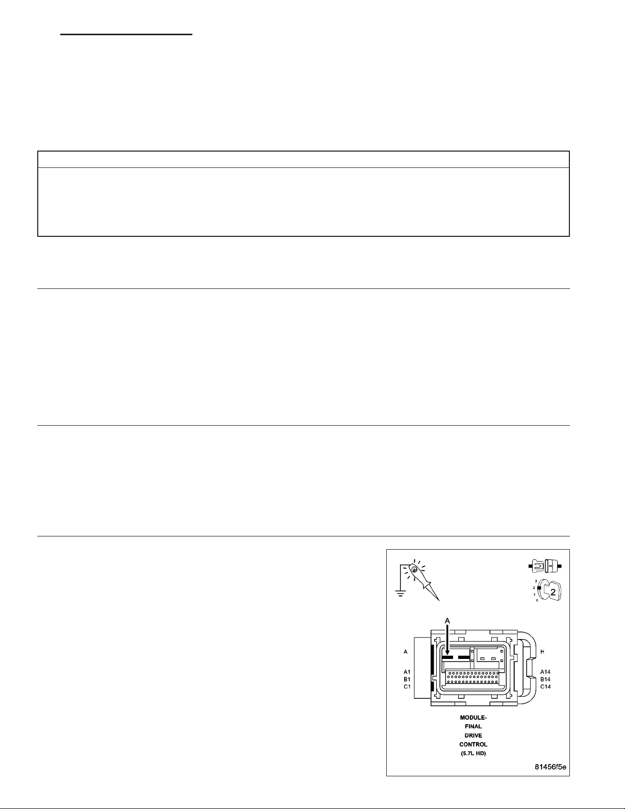
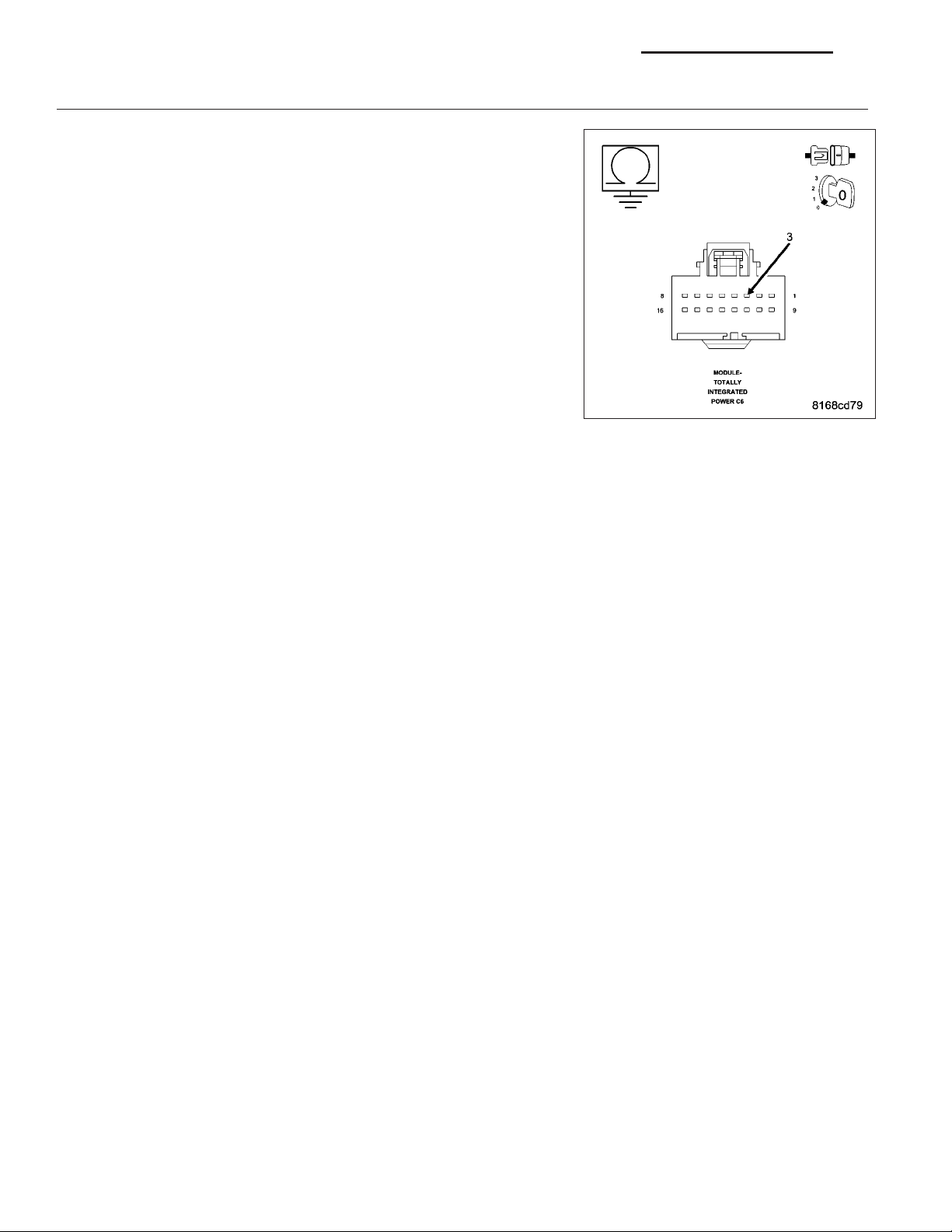
(A34) FUSED B+ CIRCUIT OPEN OR HIGH RESISTANCE
3.
Turn the ignition off.
Disconnect the Final Drive Control Module harness connector.
Turn the ignition on.
With a 12–volt test light connected to ground, check the (A34) Fused
B+ circuit in the Final Drive Control Module harness connector.
NOTE: The test light must illuminate brightly. Compare the brightness to that of a direct connection to the battery.
Does the test light illuminate brightly?
Refer to the symptom list and perform any Charging System DTC diagnostic procedures before continuing with this test.
Go to 2
Go to 3
Go to 5
Yes >>
No >>
Go to 4
Repair the (A34) Fused B+ circuit for an open circuit or high
resistance.
Perform the FDCM VERIFICATION TEST. (Refer to 3 - DIF-
FERENTIAL & DRIVELINE - STANDARD PROCEDURE)
Page 10

8E - 10 ELECTRONIC CONTROL MODULES - ELECTRICAL DIAGNOSTICS DR
FINAL DRIVE CONTROL MODULE
4.
View repair.
Repair
Replace the Final Drive Control Module in accordance with the Service information.
Perform the FDCM VERIFICATION TEST. (Refer to 3 - DIFFERENTIAL & DRIVELINE - STANDARD
PROCEDURE)
INTERMITTENT WIRING AND CONNECTORS
5.
The conditions necessary to set this DTC are not present at this time.
Using the wiring diagram/schematic as a guide, inspect the wiring and connectors.
While monitoring the scan tool data relative to this circuit, wiggle test the wiring and connectors.
Look for the data to change or for the DTC to reset during the wiggle test.
Were any problems found?
Yes >>
No >>
Repair as necessary.
Perform the FDCM VERIFICATION TEST. (Refer to 3 - DIFFERENTIAL & DRIVELINE - STANDARD
PROCEDURE)
Test complete.
Page 11

DR ELECTRONIC CONTROL MODULES - ELECTRICAL DIAGNOSTICS 8E - 11
C2101–BATTERY VOLTAGE HIGH (FDCM)
For a complete wiring diagram Refer to Section 8W
• When Monitored:
Continuously.
• Set Condition:
The Final Drive Control Module detects that system voltage is above 16.0 volts for 10 seconds with engine
RPM greater than 350.
Possible Causes
INTERMITTENT BATTERY VOLTAGE HIGH
CHARGING SYSTEM DTCS PRESENT
FINAL DRIVE CONTROL MODULE GROUND CIRCUITS OPEN OR HIGH RESISTANCE
FINAL DRIVE CONTROL MODULE
Diagnostic Test
CHARGING SYSTEM DTCS PRESENT
1.
Ignition on.
With the scan tool, select View DTCs in the Powertrain Control Module.
Are there any Charging System or related voltage DTCs present?
Yes >>
No >>
DTC IS ACTIVE
2.
With the scan tool, select View DTCs in the Final Drive Control Module.
Is the status Active for this DTC?
Yes >>
No >>
Refer to the symptom list and perform any Charging System DTC diagnostic procedures before continuing with this test.
Go to 2
Go to 3
Go to 5
Page 12
8E - 12 ELECTRONIC CONTROL MODULES - ELECTRICAL DIAGNOSTICS DR
FINAL DRIVE CONTROL MODULE GROUND CIRCUITS OPEN OR HIGH RESISTANCE
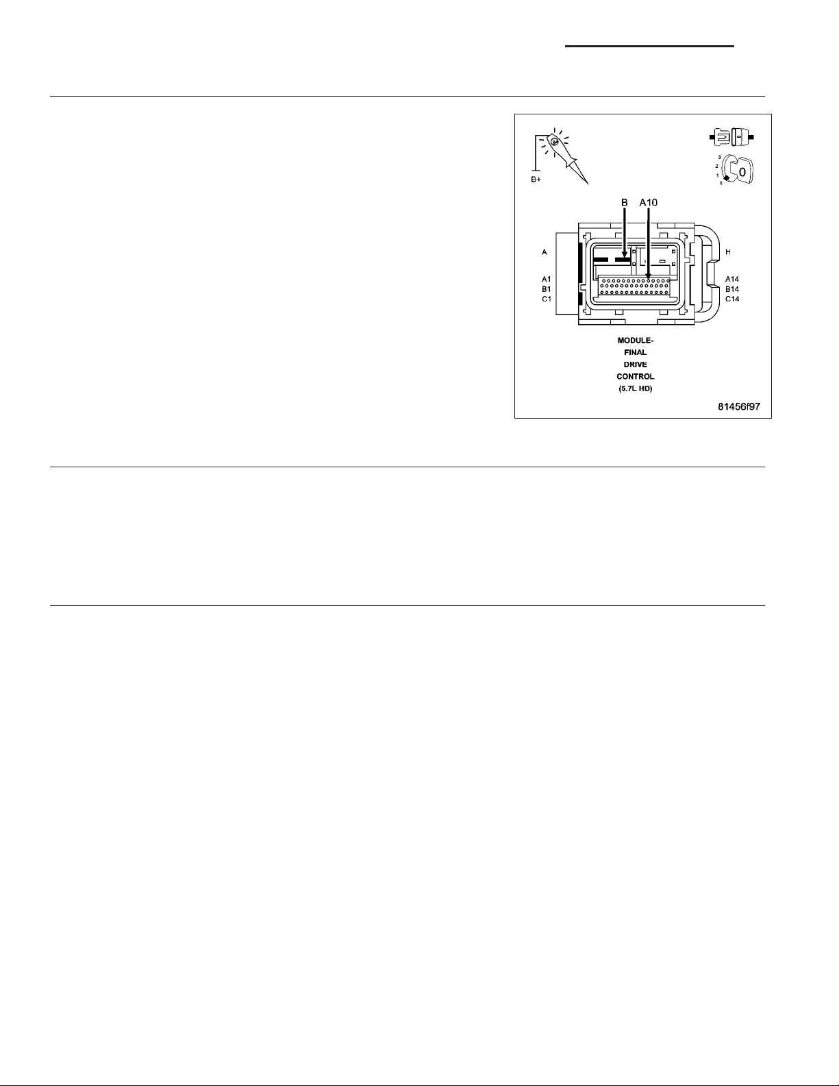
3.
Turn the ignition off.
Disconnect the Final Drive Control Module harness connector.
Turn the ignition on.
With a 12–volt test light connected to B+, check the Ground circuits in
the Final Drive Control Module harness connector.
NOTE: The test light must illuminate brightly. Compare the brightness to that of a direct connection to the battery.
Does the test light illuminate brightly for each of the Ground
circuits?
Yes >>
No >>
FINAL DRIVE CONTROL MODULE
4.
View repair.
Repair
INTERMITTENT WIRING AND CONNECTORS
5.
The conditions necessary to set this DTC are not present at this time.
Using the wiring diagram/schematic as a guide, inspect the wiring and connectors.
While monitoring the scan tool data relative to this circuit, wiggle test the wiring and connectors.
Look for the data to change or for the DTC to reset during the wiggle test.
Were any problems found?
Go to 4
Repair the Ground circuit(s) for an open circuit or high
resistance.
Perform the FDCM VERIFICATION TEST. (Refer to 3 - DIF-
FERENTIAL & DRIVELINE - STANDARD PROCEDURE)
Replace the Final Drive Control Module in accordance with the Service information.
Perform the FDCM VERIFICATION TEST. (Refer to 3 - DIFFERENTIAL & DRIVELINE - STANDARD
PROCEDURE)
Yes >>
No >>
Repair as necessary.
Perform the FDCM VERIFICATION TEST. (Refer to 3 - DIFFERENTIAL & DRIVELINE - STANDARD
PROCEDURE)
Test complete.
Page 13

DR ELECTRONIC CONTROL MODULES - ELECTRICAL DIAGNOSTICS 8E - 13
C2201-FDCM ECU INTERNAL (FDCM)
For a complete wiring diagram Refer to Section 8W
• When Monitored:
With the ignition on.
• Set Condition:
The Final Drive Control Module has detected a failure internal to the controller.
Possible Causes
FINAL DRIVE CONTROL MODULE
FINAL DRIVE CONTROL MODULE
1.
The Final Drive Control Module has detected an internal failure.
View repair
Repair
Replace the Final Drive Control Module in accordance with the Service Information.
Perform the FDCM VERIFICATION TEST. (Refer to 3 - DIFFERENTIAL & DRIVELINE - STANDARD
PROCEDURE)
Page 14
8E - 14 ELECTRONIC CONTROL MODULES - ELECTRICAL DIAGNOSTICS DR
U0001-CAN C BUS CIRCUIT
For a complete wiring diagram Refer to Section 8W.
Page 15

DR ELECTRONIC CONTROL MODULES - ELECTRICAL DIAGNOSTICS 8E - 15
• When Monitored:
With the ignition on.
• Set Condition:
The TIPM detects a short in either CAN C Bus circuit.
Possible Causes
(D65) CAN C BUS (+) CIRCUIT SHORTED TO GROUND
(D64) CAN C BUS (-) CIRCUIT SHORTED TO GROUND
(D65) CAN C BUS (+) CIRCUIT SHORTED TO VOLTAGE
(D64) CAN C BUS (-) CIRCUIT SHORTED TO VOLTAGE
(D65) CAN C BUS (+) CIRCUIT SHORTED TO (D64) CAN C BUS (-) CIRCUIT
ANTILOCK BRAKE MODULE
POWERTRAIN CONTROL MODULE
ENGINE CONTROL MODULE (DIESEL ONLY)
GATEWAY MODULE (SRT10 ONLY)
FINAL DRIVE CONTROL MODULE
TOTALLY INTEGRATED POWER MODULE
Diagnostic Test
TEST FOR INTERMITTENT CONDITION
1.
Turn the ignition on.
With the scan tool, record and erase TIPM DTC’s.
Cycle the ignition from on to off 3 times.
Turn the ignition on.
With the scan tool, read active TIPM DTC’s.
Does the scan tool display U0001–CAN C BUS CIRCUIT as active?
Yes >>
No >>
ANTILOCK BRAKE MODULE — INTERNAL SHORT
2.
Turn the ignition off.
Disconnect the Antilock Brake Module harness connector.
Turn the ignition on.
With the scan tool, record and erase TIPM DTC’s.
Cycle the ignition from on to off 3 times.
Turn the ignition on.
With the scan tool, read active TIPM DTC’s.
Does the scan tool display U0001–CAN C BUS CIRCUIT as active?
Go To 2
The conditions that caused this code to set are not present at this time. Using the wiring diagram/sche-
matic as a guide, inspect the wiring and connectors.
Yes >>
No >>
Go To 3
Inspect the wiring and connectors for damage or shorted circuits. If ok, replace the Antilock Brake Mod-
ule in accordance with the service information.
Perform the ABS VERIFICATION TEST — VER 1.
Page 16

8E - 16 ELECTRONIC CONTROL MODULES - ELECTRICAL DIAGNOSTICS DR
POWERTRAIN CONTROL MODULE — INTERNAL SHORT
3.
Turn the ignition off.
Disconnect the Powertrain Control Module C1 harness connector.
Turn the ignition on.
With the scan tool, record and erase TIPM DTC’s.
Cycle the ignition from on to off 3 times.
Turn the ignition on.
With the scan tool, read active TIPM DTC’s.
Does the scan tool display U0001–CAN C BUS CIRCUIT as active?
Yes >>
No >>
GATEWAY MODULE (SRT10 ONLY) — INTERNAL SHORT
4.
Turn the ignition off.
NOTE: If vehicle is not equipped with this module, answer yes to the question.
Disconnect the Gateway Module harness connector.
Turn the ignition on.
With the scan tool, record and erase TIPM DTC’s.
Cycle the ignition from on to off 3 times.
Turn the ignition on.
With the scan tool, read active TIPM DTC’s.
Does the scan tool display U0001–CAN C BUS CIRCUIT as active?
Yes >>
No >>
Go To 4
Inspect the wiring and connectors for damage or shorted circuits. If ok, replace and program the Pow-
ertrain Control Module in accordance with the service information.
Perform the POWERTRAIN VERIFICATION TEST
Go To 5
Inspect the wiring and connectors for damage or shorted circuits. If ok, replace the Gateway Module in
accordance with the service information.
Perform the BODY VERIFICATION TEST – VER 1. (Refer to 8 - ELECTRICAL/ELECTRONIC CON-
TROL MODULES - STANDARD PROCEDURE)
ENGINE CONTROL MODULE (DIESEL ONLY) — INTERNAL SHORT
5.
Turn the ignition off.
NOTE: If vehicle is not equipped with this module, answer yes to the question.
Disconnect the Engine Control Module C1 harness connector.
Turn the ignition on.
With the scan tool, record and erase TIPM DTC’s.
Cycle the ignition from on to off 3 times.
Turn the ignition on.
With the scan tool, read active TIPM DTC’s.
Does the scan tool display U0001–CAN C BUS CIRCUIT as active?
Yes >>
No >>
Go To 6
Inspect the wiring and connectors for damage or shorted circuits. If ok, replace and program the Engine
Control Module in accordance with the service information.
Perform the POWERTRAIN VERIFICATION TEST VER - 5 (DIESEL).
Page 17
DR ELECTRONIC CONTROL MODULES - ELECTRICAL DIAGNOSTICS 8E - 17
FINAL DRIVE CONTROL MODULE (POWER WAGON ONLY) — INTERNAL SHORT
6.
Turn the ignition off.
NOTE: If vehicle is not equipped with this module, answer yes to the question.
Disconnect the Final Drive Control Module harness connectors.
Turn the ignition on.
With the scan tool, record and erase TIPM DTC’s.
Cycle the ignition from on to off 3 times.
Turn the ignition on.
With the scan tool, read active TIPM DTC’s.
Does the scan tool display U0001–CAN C BUS CIRCUIT as active?
Yes >>
No >>
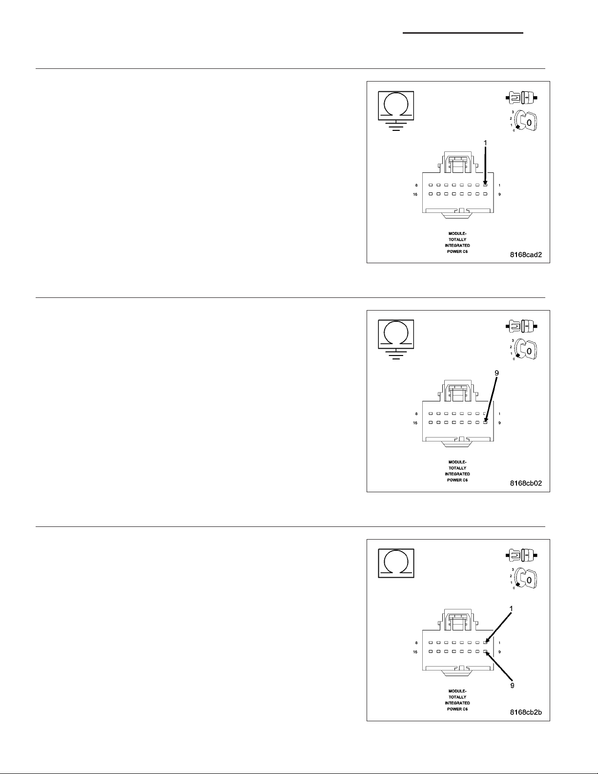
(D65) CAN C BUS (+) CIRCUIT SHORTED TO VOLTAGE
7.
Turn the ignition off.
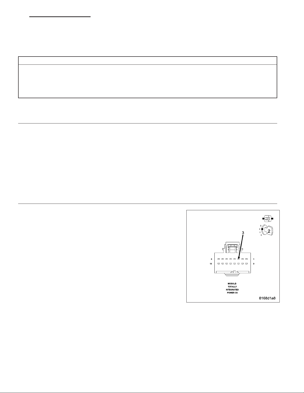
Disconnect the Totally Integrated Power Module C6 harness connector.
Turn the ignition on.
Measure the voltage between the (D65) CAN C Bus (+) circuit and
ground.
Is there any voltage present?
Yes >>
No >>
Go To 7
Inspect the wiring and connectors for damage or shorted circuits. If ok, replace and program the Final
Drive Control Module in accordance with the service information.
Perform the FDCM VERIFICATION TEST.
Repair the (D65) CAN C Bus (+) circuit for a short to voltage.
Perform the BODY VERIFICATION TEST – VER 1. (Refer
to 8 - ELECTRICAL/ELECTRONIC CONTROL MODULES STANDARD PROCEDURE)
Go To 8
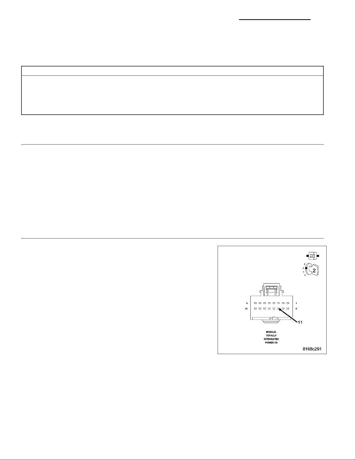
(D64) CAN C BUS (-) CIRCUIT SHORTED TO VOLTAGE
8.
Measure the voltage between the (D64) CAN C Bus (-) circuit and
ground.
Is there any voltage present?
Yes >>
No >>
Repair the (D64) CAN C Bus (-) circuit for a short to voltage.
Perform the BODY VERIFICATION TEST – VER 1. (Refer
to 8 - ELECTRICAL/ELECTRONIC CONTROL MODULES STANDARD PROCEDURE).
Go To 9
Page 18
8E - 18 ELECTRONIC CONTROL MODULES - ELECTRICAL DIAGNOSTICS DR
(D65) CAN C BUS (+) CIRCUIT SHORTED TO GROUND
9.
Turn the ignition off.
Measure the resistance between ground and the (D65) CAN C Bus (+)
circuit.
Is any resistance present?
Yes >>
No >>
10.
Measure the resistance between ground and the (D64) CAN C Bus (-)
circuit.
Is any resistance present?
Yes >>
No >>
Repair the (D65) CAN C Bus (+) circuit for a short to
ground.
Perform the BODY VERIFICATION TEST – VER 1. (Refer
to 8 - ELECTRICAL/ELECTRONIC CONTROL MODULES STANDARD PROCEDURE).
Go To 10
(D64) CAN C BUS (-) CIRCUIT SHORTED TO GROUND
Repair the (D64) CAN C Bus (-) circuit for a short to
ground.
Perform the BODY VERIFICATION TEST – VER 1. (Refer
to 8 - ELECTRICAL/ELECTRONIC CONTROL MODULES STANDARD PROCEDURE).
Go To 11
(D65) CAN C BUS (+) CIRCUIT SHORTED TO (D64) CAN C BUS (-) CIRCUIT
11.
Measure the resistance between the (D65) CAN C Bus (+) circuit and
the (D64) CAN C Bus (-) circuit.
Is any resistance present?
Yes >>
No >>
Repair the (D65) CAN C Bus (+) circuit for a short to the
(D64) CAN C Bus (-) circuit.
Perform the BODY VERIFICATION TEST – VER 1. (Refer
to 8 - ELECTRICAL/ELECTRONIC CONTROL MODULES STANDARD PROCEDURE).
Inspect the wiring and connectors for damage or shorted
circuits. If ok, replace and program the Totally Integrated
Power Module in accordance with the service information.
Perform the BODY VERIFICATION TEST – VER 1. (Refer
to 8 - ELECTRICAL/ELECTRONIC CONTROL MODULES STANDARD PROCEDURE).
Page 19

DR ELECTRONIC CONTROL MODULES - ELECTRICAL DIAGNOSTICS 8E - 19
U0021-CAN B BUS (+) CIRCUIT OPEN
For a complete wiring diagram Refer to Section 8W.
Page 20
8E - 20 ELECTRONIC CONTROL MODULES - ELECTRICAL DIAGNOSTICS DR
• When Monitored:
With the ignition on and battery voltage between 10 and 16 volts.
• Set Condition:
The TIPM detects the (D55) CAN B Bus (+) circuit is open.
Possible Causes
CAN B BUS TERMINAL PUSH OUT
SPREAD CAN B BUS TERMINAL
(D55) CAN B BUS (+) CIRCUIT OPEN
INTERNAL OPEN IN A CAN B BUS MODULE
Diagnostic Test
TEST FOR INTERMITTENT CONDITION
1.
Turn the ignition on.
With the scan tool, record and erase TIPM DTC’s.
Cycle the ignition from on to off 3 times.
Turn the ignition on.
With the scan tool, read active TIPM DTC’s.
Does the scan tool display this DTC as active?
Yes >>
No >>
ATTEMPT TO ISOLATE THE OPEN CONDITION
2.
Turn the ignition on.
Verify that all CAN B Bus modules are communicating with the scan
tool.
NOTE: A red X will be next to the module that is not communicating, indicating that the module is not active on the Bus network. A
green check indicates that the module is active on the Bus network.
NOTE: If any module is not communicating, perform the appropriate no response test procedure before proceeding.
Turn the ignition off.
Gain access to the Totally Integrated Power Module C6 harness con-
nector, but do not disconnect.
Using a fused jumper wire, connect one end to ground and with the
other end backprobe the (D54) CAN B Bus (-) circuit at the TIPM C6
harness connector.
Turn the ignition on.
With the scan tool monitor the network status screen and document all modules that display a red X.
Are there any red X’s displayed next to the modules?
Go To 2
The conditions that caused this code to set are not present at this time. Using the wiring diagram/sche-
matic as a guide, inspect the wiring and connectors.
Yes >>
No >>
Go To 3
Check backprobe connection to ground, make sure it is proper. The CAN B Bus open DTC may no
longer be active, it may be stored. Check all module connections.
Perform BODY VERIFICATION TEST – VER 1. (Refer to 8 - ELECTRICAL/ELECTRONIC CONTROL
MODULES - STANDARD PROCEDURE).
Page 21

DR ELECTRONIC CONTROL MODULES - ELECTRICAL DIAGNOSTICS 8E - 21
ATTEMPT TO ISOLATE THE OPEN CONDITION — MULTIPLE RED X’S
3.
With the scan tool continue monitoring the network status screen.
Are there multiple red X’s displayed next to the modules?
Yes >>
No >>
(D55) CAN B BUS (+) CIRCUIT OPEN — SINGLE RED X
4.
Turn the ignition off.
Disconnect the module that has the red X displayed next to it.
Turn the ignition on.
Measure the voltage between the (D55) CAN B Bus (+) circuit and ground.
Is there any voltage present?
Yes >>
No >>
The most likely cause of this condition is an open CAN B Bus (+) circuit between a common CAN B
Bus splice and the modules that display the red X next to them. Using the wiring diagrams will help you
determine where open condition exists.
Perform BODY VERIFICATION TEST – VER 1. (Refer to 8 - ELECTRICAL/ELECTRONIC CONTROL
MODULES - STANDARD PROCEDURE).
Go To 4
Inspect the connector and terminal for damage, inspect for spread terminals, or push out terminals. If
ok, replace the module that displayed the red X next to it in accordance with the service information.
Perform BODY VERIFICATION TEST – VER 1. (Refer to 8 - ELECTRICAL/ELECTRONIC CONTROL
MODULES - STANDARD PROCEDURE).
Repair the (D55) CAN B Bus (+) circuit for an open between the next common splice and the module
that has the red X displayed next to it. Using the wiring diagrams will help you determine where open
condition exists.
Perform BODY VERIFICATION TEST – VER 1. (Refer to 8 - ELECTRICAL/ELECTRONIC CONTROL
MODULES - STANDARD PROCEDURE).
Page 22
8E - 22 ELECTRONIC CONTROL MODULES - ELECTRICAL DIAGNOSTICS DR
U0022-CAN B BUS (+) CIRCUIT LOW
For a complete wiring diagram Refer to Section 8W.
Page 23
DR ELECTRONIC CONTROL MODULES - ELECTRICAL DIAGNOSTICS 8E - 23
• When Monitored:
Continuously.
• Set Condition:
The TIPM detects the (D55) CAN B Bus (+) circuit is shorted to ground.
Possible Causes
(D55) CAN B BUS (+) CIRCUIT SHORTED TO GROUND
ANY CAN B BUS MODULE
TOTALLY INTEGRATED POWER MODULE
Diagnostic Test
TEST FOR INTERMITTENT CONDITION
1.
Turn the ignition on.
With the scan tool, record and erase TIPM DTC’s.
Cycle the ignition from on to off 3 times.
Turn the ignition on.
With the scan tool, read active TIPM DTC’s.
Does the scan tool display this DTC as active?
Yes >>
No >>
CHECK THE (D55) CAN B BUS (+) CIRCUIT FOR A SHORT TO GROUND
2.
Turn the ignition off.
Disconnect the Totally Integrated Power Module C6 harness connector.
Measure the resistance between ground and the (D55) CAN B Bus (+)
circuit.
Is resistance below 1000.0 ohms?
Yes >>
No >>
Go To 2
The conditions that caused this code to set are not present at this time. Using the wiring diagram/sche-
matic as a guide, inspect the wiring and connectors.
Go To 3
Inspect the wiring and connectors for damage or shorted
circuits. If ok, replace the Totally Integrated Power Module
in accordance with the service information.
Perform BODY VERIFICATION TEST – VER 1. (Refer to 8
- ELECTRICAL/ELECTRONIC CONTROL MODULES STANDARD PROCEDURE).
Page 24
8E - 24 ELECTRONIC CONTROL MODULES - ELECTRICAL DIAGNOSTICS DR
(D55) CAN B BUS (+) CIRCUIT SHORTED TO GROUND
3.
Measure the resistance between ground and the (D55) CAN B Bus (+)
circuit.
While monitoring the ohmmeter, disconnect each CAN B Bus module
one at a time.
NOTE: This is to determine if the short to ground is internal within
a module or if the circuit is shorted.
NOTE: Disconnecting an in-line connector can eliminate a module
or group of modules from the list of possible causes for this fault.
Refer to the wiring diagrams to assist in diagnosis.
Is resistance below 1000.0 ohms with all the CAN B Bus modules disconnected?
Yes >>
No >>
Repair the (D55) CAN B Bus (+) circuit for a short to
ground.
Perform BODY VERIFICATION TEST – VER 1. (Refer to 8
- ELECTRICAL/ELECTRONIC CONTROL MODULES STANDARD PROCEDURE).
Replace the module that when disconnected the short to ground was eliminated, in accordance with the
service information.
Perform BODY VERIFICATION TEST – VER 1. (Refer to 8 - ELECTRICAL/ELECTRONIC CONTROL
MODULES - STANDARD PROCEDURE).
Page 25
DR ELECTRONIC CONTROL MODULES - ELECTRICAL DIAGNOSTICS 8E - 25
U0023-CAN B BUS (+) CIRCUIT HIGH
For a complete wiring diagram Refer to Section 8W.
Page 26
8E - 26 ELECTRONIC CONTROL MODULES - ELECTRICAL DIAGNOSTICS DR
• When Monitored:
Continuously
• Set Condition:
The TIPM detects the (D55) CAN B Bus (+) circuit is shorted to voltage.
Possible Causes
(D55) CAN B BUS (+) CIRCUIT SHORTED TO VOLTAGE
ANY CAN B BUS MODULE
TOTALLY INTEGRATED POWER MODULE
Diagnostic Test
TEST FOR INTERMITTENT CONDITION
1.
Turn the ignition on.
With the scan tool, record and erase TIPM DTC’s.
Cycle the ignition from on to off 3 times.
Turn the ignition on.
With the scan tool, read active TIPM DTC’s.
Does the scan tool display this DTC as active?
Yes >>
No >>
CHECK THE (D55) CAN B BUS (+) CIRCUIT FOR A SHORT TO VOLTAGE
2.
Turn the ignition off.
Disconnect the Totally Integrated Power Module C6 harness connector.
Turn the ignition on.
Measure the voltage between the (D55) CAN B Bus (+) circuit and
ground.
Is voltage above 10.0 volts?
Yes >>
No >>
Go To 2
The conditions that caused this code to set are not present at this time. Using the wiring diagram/sche-
matic as a guide, inspect the wiring and connectors.
Go To 3
Inspect the wiring and connectors for damage or shorted
circuits. If ok, replace the Totally Integrated Power Module
in accordance with the service information.
Perform BODY VERIFICATION TEST – VER 1. (Refer to 8
- ELECTRICAL/ELECTRONIC CONTROL MODULES STANDARD PROCEDURE).
Page 27
DR ELECTRONIC CONTROL MODULES - ELECTRICAL DIAGNOSTICS 8E - 27
(D55) CAN B BUS (+) CIRCUIT SHORTED TO VOLTAGE
3.
Measure the voltage between the (D55) CAN B Bus (+) circuit and
ground.
While monitoring the voltmeter, disconnect each CAN B Bus module
one at a time.
NOTE: When performing the above step, turn the ignition off (wait
one minute) before disconnecting any module. When the module is
disconnected turn the ignition on to check for a short to voltage.
NOTE: This is to determine if the short to voltage is internal within
a module or if the circuit is shorted.
NOTE: Disconnecting an in-line connector can eliminate a module
or group of modules from the list of possible causes for this fault.
Refer to the wiring diagrams to assist in diagnosis.
Is the voltage above 10.0 volts with all the CAN B Bus modules disconnected?
Yes >>
No >>
Repair the (D55) CAN B Bus (+) circuit for a short to voltage.
Perform BODY VERIFICATION TEST – VER 1. (Refer to 8 - ELECTRICAL/ELECTRONIC CONTROL
MODULES - STANDARD PROCEDURE).
Replace the module that when disconnected the short to voltage was eliminated, in accordance with the
service information.
Perform BODY VERIFICATION TEST – VER 1. (Refer to 8 - ELECTRICAL/ELECTRONIC CONTROL
MODULES - STANDARD PROCEDURE).
Page 28

8E - 28 ELECTRONIC CONTROL MODULES - ELECTRICAL DIAGNOSTICS DR
U0024-CAN B BUS (-) CIRCUIT OPEN
For a complete wiring diagram Refer to Section 8W.
Page 29
DR ELECTRONIC CONTROL MODULES - ELECTRICAL DIAGNOSTICS 8E - 29
• When Monitored:
With the ignition on and battery voltage between 10 and 16 volts.
• Set Condition:
The TIPM detects the (D54) CAN B Bus (-) circuit is open.
Possible Causes
CAN B BUS TERMINAL PUSH OUT
SPREAD CAN B BUS TERMINAL
(D54) CAN B BUS (-) CIRCUIT OPEN
INTERNAL OPEN IN A CAN B BUS MODULE
Diagnostic Test
TEST FOR INTERMITTENT CONDITION
1.
Turn the ignition on.
With the scan tool, record and erase TIPM DTC’s
Cycle the ignition from on to off 3 times.
Turn the ignition on.
With the scan tool, read active TIPM DTC’s.
Does the scan tool display this DTC as active?
Yes >>
No >>
ATTEMPT TO ISOLATE THE OPEN CONDITION
2.
Turn the ignition on.
Verify that all CAN B Bus modules are communicating with the scan
tool.
NOTE: A red X will be next to the module that is not communicating, indicating that the module is not active on the Bus network. A
green check indicates that the module is active on the Bus network.
NOTE: If any module is not communicating, perform the appropriate no response test procedure before proceeding.
Turn the ignition off.
Gain access to the Totally Integrated Power Module C6 harness con-
nector, but do not disconnect.
Using a fused jumper wire, connect one end to ground and with the
other end backprobe the CAN B Bus (+) circuit at the TIPM C6 harness
connector.
Turn the ignition on.
With the scan tool monitor the network status screen and document all modules that display a red X.
Are there any red X’s displayed next to the modules?
Go To 2
The conditions that caused this code to set are not present at this time. Using the wiring diagram/sche-
matic as a guide, inspect the wiring and connectors.
Yes >>
No >>
Go To 3
Check backprobe connection to ground, make sure it is proper. The CAN B Bus open DTC may no
longer be active, it may be stored. Check all module connections
Perform BODY VERIFICATION TEST – VER 1. (Refer to 8 - ELECTRICAL/ELECTRONIC CONTROL
MODULES - STANDARD PROCEDURE).
Page 30

8E - 30 ELECTRONIC CONTROL MODULES - ELECTRICAL DIAGNOSTICS DR
ATTEMPT TO ISOLATE THE OPEN CONDITION — MULTIPLE RED X’S
3.
With the scan tool continue monitoring the network status screen.
Are there multiple red X’s displayed next to the modules?
Yes >>
No >>
(D54) CAN B BUS (-) CIRCUIT OPEN — SINGLE RED X
4.
Turn the ignition off.
Disconnect the module that has the red X displayed next to it.
Turn the ignition on.
Measure the voltage between the (D54) CAN B Bus (-) circuit and ground.
Is there any voltage present?
Yes >>
No >>
The most likely cause of this condition is an open CAN B Bus (-) circuit between a common CAN B Bus
splice and the modules that display the red X next to them. Using the wiring diagrams will help you
determine where open condition exists.
Perform BODY VERIFICATION TEST – VER 1. (Refer to 8 - ELECTRICAL/ELECTRONIC CONTROL
MODULES - STANDARD PROCEDURE).
Go To 4
Inspect the connector and terminal for damage, inspect for spread terminals, or push out terminals. If
ok, replace the module that displayed the red X next to it in accordance with the service information.
Perform BODY VERIFICATION TEST – VER 1. (Refer to 8 - ELECTRICAL/ELECTRONIC CONTROL
MODULES - STANDARD PROCEDURE).
Repair the (D54) CAN B Bus (-) circuit for an open between the next common splice and the module
that has the red X displayed next to it. Using the wiring diagrams will help you determine where open
condition exists.
Perform BODY VERIFICATION TEST – VER 1. (Refer to 8 - ELECTRICAL/ELECTRONIC CONTROL
MODULES - STANDARD PROCEDURE).
Page 31

DR ELECTRONIC CONTROL MODULES - ELECTRICAL DIAGNOSTICS 8E - 31
U0025-CAN B BUS (-) CIRCUIT LOW
For a complete wiring diagram Refer to Section 8W.
Page 32

8E - 32 ELECTRONIC CONTROL MODULES - ELECTRICAL DIAGNOSTICS DR
• When Monitored:
Continuously
• Set Condition:
The TIPM detects the (D54) CAN B Bus (-) circuit is shorted to ground.
Possible Causes
(D54) CAN B BUS (-) CIRCUIT SHORTED TO GROUND OR TO (D55) CAN B BUS (+) CIRCUIT
ANY CAN B BUS MODULE
TOTALLY INTEGRATED POWER MODULE
Diagnostic Test
TEST FOR INTERMITTENT CONDITION
1.
Turn the ignition on.
With the scan tool, record and erase TIPM DTC’s.
Cycle the ignition from on to off 3 times.
Turn the ignition on.
With the scan tool, read active TIPM DTC’s.
Does the scan tool display this DTC as active?
Yes >>
No >>
CHECK THE (D54) CAN B BUS (-) CIRCUIT FOR A SHORT TO GROUND
2.
Turn the ignition off.
Disconnect the Totally Integrated Power Module C6 harness connector.
Measure the resistance between ground and the (D54) CAN B Bus (-)
circuit.
Is resistance below 1000.0 ohms?
Yes >>
No >>
Go To 2
The conditions that caused this code to set are not present at this time. Using the wiring diagram/sche-
matic as a guide, inspect the wiring and connectors.
Go To 3
Go To 4
Page 33

DR ELECTRONIC CONTROL MODULES - ELECTRICAL DIAGNOSTICS 8E - 33
(D54) CAN B BUS (-) CIRCUIT SHORTED TO GROUND
3.
Measure the resistance between ground and the (D54) CAN B Bus (-)
circuit.
While monitoring the ohmmeter, disconnect each CAN B Bus module
one at a time.
NOTE: This is to determine if the short to ground is internal within
a module or if the circuit is shorted.
NOTE: Disconnecting an in-line connector can eliminate a module
or group of modules from the list of possible causes for this fault.
Refer to the wiring diagrams to assist in diagnosis.
Is resistance below 1000.0 ohms with all the CAN B Bus modules disconnected?
Yes >>
No >>
CHECK THE (D55) CAN B BUS (+) CIRCUIT FOR A SHORT TO THE (D54) CAN B BUS (-) CIRCUIT
4.
Measure the resistance between the (D55) CAN B Bus (+) circuit and
(D54) CAN B Bus (-) circuit.
Is resistance below 1000.0 ohms?
Yes >>
No >>
Repair the (D54) CAN B Bus (-) circuit for a short to
ground.
Perform BODY VERIFICATION TEST – VER 1. (Refer to 8
- ELECTRICAL/ELECTRONIC CONTROL MODULES STANDARD PROCEDURE).
Replace the module that when disconnected the short to ground was eliminated, in accordance with the
service information.
Perform BODY VERIFICATION TEST – VER 1. (Refer to 8 - ELECTRICAL/ELECTRONIC CONTROL
MODULES - STANDARD PROCEDURE).
Go To 5
Inspect the wiring and connectors for damage or shorted
circuits. If ok, replace the Totally Integrated Power Module
in accordance with the service information.
Perform BODY VERIFICATION TEST – VER 1. (Refer to 8
- ELECTRICAL/ELECTRONIC CONTROL MODULES STANDARD PROCEDURE).
Page 34

8E - 34 ELECTRONIC CONTROL MODULES - ELECTRICAL DIAGNOSTICS DR
(D55) CAN B BUS (+) CIRCUIT SHORTED TO THE (D54) CAN B BUS (-) CIRCUIT
5.
Measure the resistance between the (D55) CAN B Bus (+) circuit and
(D54) CAN B Bus (-) circuit.
While monitoring the ohmmeter, disconnect each CAN B Bus module
one at a time.
NOTE: This is to determine if the short together is internal within a
module or if the circuits are shorted together.
NOTE: Disconnecting an in-line connector can eliminate a module
or group of modules from the list of possible causes for this fault.
Refer to the wiring diagrams to assist in diagnosis.
Is resistance below 1000.0 ohms with all the CAN B Bus modules disconnected?
Yes >>
No >>
Repair the (D55) CAN B Bus (+) circuit for a short to the
(D54) CAN B Bus (-) circuit.
Perform BODY VERIFICATION TEST – VER 1. (Refer to 8
- ELECTRICAL/ELECTRONIC CONTROL MODULES STANDARD PROCEDURE).
Replace the module that when disconnected the short together was eliminated, in accordance with the
service information.
Perform BODY VERIFICATION TEST – VER 1. (Refer to 8 - ELECTRICAL/ELECTRONIC CONTROL
MODULES - STANDARD PROCEDURE).
Page 35

DR ELECTRONIC CONTROL MODULES - ELECTRICAL DIAGNOSTICS 8E - 35
U0026-CAN B BUS (-) CIRCUIT HIGH
For a complete wiring diagram Refer to Section 8W.
Page 36

8E - 36 ELECTRONIC CONTROL MODULES - ELECTRICAL DIAGNOSTICS DR
• When Monitored:
Continuously
• Set Condition:
The TIPM detects the (D54) CAN B Bus (-) circuit is shorted to voltage.
Possible Causes
(D54) CAN B BUS (-) CIRCUIT SHORTED TO VOLTAGE
ANY CAN B BUS MODULE
TOTALLY INTEGRATED POWER MODULE
Diagnostic Test
TEST FOR INTERMITTENT CONDITION
1.
Turn the ignition on.
With the scan tool, record and erase TIPM DTC’s.
Cycle the ignition from on to off 3 times.
Turn the ignition on.
With the scan tool, read active TIPM DTC’s.
Does the scan tool display this DTC as active?
Yes >>
No >>
CHECK THE (D54) CAN B BUS (-) CIRCUIT FOR A SHORT TO VOLTAGE
2.
Turn the ignition off.
Disconnect the Totally Integrated Power Module C6 harness connector.
Turn the ignition on.
Measure the voltage between the (D54) CAN B Bus (-) circuit and
ground.
Is voltage above 10.0 volts?
Yes >>
No >>
Go To 2
The conditions that caused this code to set are not present at this time. Using the wiring diagram/sche-
matic as a guide, inspect the wiring and connectors.
Go To 3
Inspect the wiring and connectors for damage or shorted
circuits. If ok, replace the Totally Integrated Power Module
in accordance with the service information.
Perform BODY VERIFICATION TEST – VER 1. (Refer to 8
- ELECTRICAL/ELECTRONIC CONTROL MODULES STANDARD PROCEDURE).
Page 37

DR ELECTRONIC CONTROL MODULES - ELECTRICAL DIAGNOSTICS 8E - 37
(D54) CAN B BUS (-) CIRCUIT SHORTED TO VOLTAGE
3.
Measure the voltage between the (D54) CAN B Bus (-) circuit and
ground.
While monitoring the voltmeter, disconnect each CAN B Bus module
one at a time.
NOTE: When performing the above step, turn the ignition off (wait
one minute) before disconnecting any module. When the module is
disconnected turn the ignition on to check for a short to voltage.
NOTE: This is to determine if the short to voltage is internal within
a module or if the circuit is shorted.
NOTE: Disconnecting an in-line connector can eliminate a module
or group of modules from the list of possible causes for this fault.
Refer to the wiring diagrams to assist in diagnosis.
Is the voltage above 10.0 volts with all the CAN B Bus modules disconnected?
Yes >>
No >>
Repair the (D54) CAN B Bus (-) circuit for a short to voltage.
Perform BODY VERIFICATION TEST – VER 1. (Refer to 8 - ELECTRICAL/ELECTRONIC CONTROL
MODULES - STANDARD PROCEDURE).
Replace the module that when disconnected the short to voltage was eliminated, in accordance with the
service information.
Perform BODY VERIFICATION TEST – VER 1. (Refer to 8 - ELECTRICAL/ELECTRONIC CONTROL
MODULES - STANDARD PROCEDURE).
Page 38

8E - 38 ELECTRONIC CONTROL MODULES - ELECTRICAL DIAGNOSTICS DR
U0027-CAN B BUS (-) SHORTED TO BUS (+)
For a complete wiring diagram Refer to Section 8W.
Page 39

DR ELECTRONIC CONTROL MODULES - ELECTRICAL DIAGNOSTICS 8E - 39
• When Monitored:
Continuously
• Set Condition:
The TIPM detects the (D55) CAN B Bus (+) circuit is shorted to the (D54) CAN B Bus (-) circuit.
Possible Causes
(D55) CAN B BUS (+) CIRCUIT SHORTED TO THE (D54) CAN B BUS (-) CIRCUIT
ANY CAN B BUS MODULE
TOTALLY INTEGRATED POWER MODULE
Diagnostic Test
TEST FOR INTERMITTENT CONDITION
1.
Turn the ignition on.
With the scan tool, record and erase TIPM DTC’s.
Cycle the ignition from on to off 3 times.
Turn the ignition on.
With the scan tool, read active TIPM DTC’s.
Does the scan tool display this DTC as active?
Yes >>
No >>
CHECK THE (D55) CAN B BUS (+) CIRCUIT FOR A SHORT TO THE (D54) CAN B BUS (-) CIRCUIT
2.
Turn the ignition off.
Disconnect the Totally Integrated Power Module C6 harness connector.
Measure the resistance between the (D55) CAN B Bus (+) circuit and
(D54) CAN B Bus (-) circuit.
Is resistance below 1000.0 ohms?
Yes >>
No >>
Go To 2
The conditions that caused this code to set are not present at this time. Using the wiring diagram/sche-
matic as a guide, inspect the wiring and connectors.
Go To 3
Inspect the wiring and connectors for damage or shorted
circuits. If ok, replace the Totally Integrated Power Module
in accordance with the service information.
Perform BODY VERIFICATION TEST – VER 1. (Refer to 8
- ELECTRICAL/ELECTRONIC CONTROL MODULES STANDARD PROCEDURE).
Page 40

8E - 40 ELECTRONIC CONTROL MODULES - ELECTRICAL DIAGNOSTICS DR
(D55) CAN B BUS (+) CIRCUIT SHORTED TO THE (D54) CAN B BUS (-) CIRCUIT
3.
Measure the resistance between the (D55) CAN B Bus (+) circuit and
(D54) CAN B Bus (-) circuit.
While monitoring the ohmmeter, disconnect each CAN B Bus module
one at a time.
NOTE: This is to determine if the short together is internal within a
module or if the circuits are shorted together.
NOTE: Disconnecting an in-line connector can eliminate a module
or group of modules from the list of possible causes for this fault.
Refer to the wiring diagrams to assist in diagnosis.
Is resistance below 1000.0 ohms with all the CAN B Bus modules disconnected?
Yes >>
No >>
Repair the (D55) CAN B Bus (+) circuit for a short to the
(D54) CAN B Bus (-) circuit.
Perform BODY VERIFICATION TEST – VER 1. (Refer to 8
- ELECTRICAL/ELECTRONIC CONTROL MODULES STANDARD PROCEDURE).
Replace the module that when disconnected the short together was eliminated, in accordance with the
service information.
Perform BODY VERIFICATION TEST – VER 1. (Refer to 8 - ELECTRICAL/ELECTRONIC CONTROL
MODULES - STANDARD PROCEDURE).
Page 41

DR ELECTRONIC CONTROL MODULES - ELECTRICAL DIAGNOSTICS 8E - 41
U0100-LOST COMMUNICATION WITH ECM/PCM
For a complete wiring diagram Refer to Section 8W.
Page 42

8E - 42 ELECTRONIC CONTROL MODULES - ELECTRICAL DIAGNOSTICS DR
• When Monitored:
• With the ignition on
• Battery voltage between 10 and 16 volts
• IOD fuse installed
• TIPM is configured correctly
• Set Condition:
Bus messages not received from the ECM/PCM for approximately 2 to 5 seconds.
Possible Causes
CAN B OR CAN C BUS CIRCUITS OPEN OR SHORTED
DTCS RELATED TO BATTERY VOLTAGE, IGNITION, OR VIN MESSAGES
TIPM NOT CONFIGURED CORRECTLY
ECM/PCM POWER AND GROUND
ECM/PCM
MODULE THAT SET THIS DTC
Diagnostic Test
VERIFY DTC IS ACTIVE
1.
NOTE: Ensure the IOD fuse is installed and battery voltage is between 10 and 16 volts before proceeding.
With the scan tool, read active DTCs.
Is this DTC active?
Yes >>
No >>
CHECK FOR ANY OF THE FOLLOWING ACTIVE DTCS
2.
With the scan tool, read all active DTCs from all modules.
NOTE: Check for TIPM configuration, CAN B or C hardware electrical, VIN Missing/Mismatch, battery or ignition related DTCs.
Does the scan tool display any active DTCs to the conditions listed above?
Yes >>
No >>
VERIFY THAT THE ECM/PCM IS ACTIVE ON THE BUS
3.
Turn the ignition on.
With the scan tool, select Network Diagnostics.
Verify that the ECM/PCM is active on the bus.
Is the ECM/PCM active on the bus?
Go To 2
Refer to the Stored Lost Communication test procedure. Refer to the table of contents in this section.
Diagnose and repair the DTC. Refer to the Index for a complete list of the symptoms.
Go To 3
Yes >>
No >>
Go To 4
Refer to the No Response test procedure. Refer to the table of contents in this section.
Page 43

DR ELECTRONIC CONTROL MODULES - ELECTRICAL DIAGNOSTICS 8E - 43
CHECK FOR ADDITIONAL COMMUNICATION RELATED DTCS
4.
With the scan tool, select Network Diagnostics.
Is there more than one module with active DTCs “Logged Against” the ECM/PCM?
Yes >>
No >>
Replace/update the ECM/PCM in accordance with the service information.
Perform the appropriate VERIFICATION TEST.
Replace/update the module that set this DTC in accordance with the service information.
Perform the appropriate VERIFICATION TEST.
Page 44

8E - 44 ELECTRONIC CONTROL MODULES - ELECTRICAL DIAGNOSTICS DR
U0101-LOST COMMUNICATION WITH TCM
For a complete wiring diagram Refer to Section 8W.
Page 45

DR ELECTRONIC CONTROL MODULES - ELECTRICAL DIAGNOSTICS 8E - 45
• When Monitored:
• With the ignition on
• Battery voltage between 10 and 16 volts
• IOD fuse installed
• TIPM is configured correctly
• Set Condition:
Bus messages not received from the TCM for approximately 2 to 5 seconds.
Possible Causes
CAN B OR CAN C BUS CIRCUITS OPEN OR SHORTED
DTCS RELATED TO BATTERY VOLTAGE, IGNITION, OR VIN MESSAGES
TIPM NOT CONFIGURED CORRECTLY
TCM POWER AND GROUND
TCM (PCM)
MODULE THAT SET THIS DTC
Diagnostic Test
VERIFY DTC IS ACTIVE
1.
NOTE: Ensure the IOD fuse is installed and battery voltage is between 10 and 16 volts before proceeding.
With the scan tool, read active DTCs.
Is this DTC active?
Yes >>
No >>
CHECK FOR ANY OF THE FOLLOWING ACTIVE DTCS
2.
With the scan tool, read all active DTCs from all modules.
NOTE: Check for TIPM configuration, CAN B or C hardware electrical, VIN Missing/Mismatch, battery or ignition related DTCs.
Does the scan tool display any active DTCs to the conditions listed above?
Yes >>
No >>
VERIFY THAT THE TCM IS ACTIVE ON THE BUS
3.
Turn the ignition on.
With the scan tool, select Network Diagnostics.
Verify that the TCM is active on the bus.
Is the TCM active on the bus?
Go To 2
Refer to the Stored Lost Communication test procedure. Refer to the table of contents in this section.
Diagnose and repair the DTC. Refer to the Index for a complete list of the symptoms.
Go To 3
Yes >>
No >>
Go To 4
Refer to the No Response test procedure. Refer to the table of contents in this section.
Page 46

8E - 46 ELECTRONIC CONTROL MODULES - ELECTRICAL DIAGNOSTICS DR
CHECK FOR ADDITIONAL COMMUNICATION RELATED DTCS
4.
With the scan tool, select Network Diagnostics.
Is there more than one module with active DTCs “Logged Against” the TCM?
Yes >>
No >>
Replace/update the TCM (PCM) in accordance with the service information.
Perform the appropriate VERIFICATION TEST.
Replace/update the module that set this DTC in accordance with the service information.
Perform the appropriate VERIFICATION TEST.
Page 47

DR ELECTRONIC CONTROL MODULES - ELECTRICAL DIAGNOSTICS 8E - 47
U0114-LOST COMMUNICATION WITH FINAL DRIVE CONTROL MODULE
For a complete wiring diagram Refer to Section 8W.
Page 48

8E - 48 ELECTRONIC CONTROL MODULES - ELECTRICAL DIAGNOSTICS DR
• When Monitored:
• With the ignition on
• Battery voltage between 10 and 16 volts
• IOD fuse installed
• TIPM is configured correctly
• Set Condition:
Bus messages not received from the Final Drive Control Module (FDCM) for approximately 2 to 5 seconds.
Possible Causes
CAN B OR CAN C BUS CIRCUITS OPEN OR SHORTED
DTCS RELATED TO BATTERY VOLTAGE, IGNITION, OR VIN MESSAGES
TIPM NOT CONFIGURED CORRECTLY
FINAL DRIVE CONTROL MODULE POWER AND GROUND
FINAL DRIVE CONTROL MODULE
MODULE THAT SET THIS DTC
Diagnostic Test
VERIFY DTC IS ACTIVE
1.
NOTE: Ensure the IOD fuse is installed and battery voltage is between 10 and 16 volts before proceeding.
With the scan tool, read active DTCs.
Is this DTC active?
Yes >>
No >>
CHECK FOR ANY OF THE FOLLOWING ACTIVE DTCS
2.
With the scan tool, read all active DTCs from all modules.
NOTE: Check for TIPM configuration, CAN B or C hardware electrical, VIN Missing/Mismatch, battery or ignition related DTCs.
Does the scan tool display any active DTCs to the conditions listed above?
Yes >>
No >>
VERIFY THAT THE FDCM IS ACTIVE ON THE BUS
3.
Turn the ignition on.
With the scan tool, select Network Diagnostics.
Verify that the FDCM is active on the bus.
Is the FDCM active on the bus?
Go To 2
Refer to the Stored Lost Communication test procedure. Refer to the table of contents in this section.
Diagnose and repair the DTC. Refer to the Index for a complete list of the symptoms.
Go To 3
Yes >>
No >>
Go To 4
Refer to the No Response test procedure. Refer to the table of contents in this section.
Page 49

DR ELECTRONIC CONTROL MODULES - ELECTRICAL DIAGNOSTICS 8E - 49
CHECK FOR ADDITIONAL COMMUNICATION RELATED DTCS
4.
With the scan tool, select Network Diagnostics.
Is there more than one module with active DTCs “Logged Against” the FDCM?
Yes >>
No >>
Replace/update the Final Drive Control Module in accordance with the service information.
Perform the appropriate VERIFICATION TEST.
Replace/update the module that set this DTC in accordance with the service information.
Perform the appropriate VERIFICATION TEST.
Page 50

8E - 50 ELECTRONIC CONTROL MODULES - ELECTRICAL DIAGNOSTICS DR
U0121-LOST COMMUNICATION WITH ANTI-LOCK BRAKE MODULE
For a complete wiring diagram Refer to Section 8W.
Page 51

DR ELECTRONIC CONTROL MODULES - ELECTRICAL DIAGNOSTICS 8E - 51
• When Monitored:
• With the ignition on
• Battery voltage between 10 and 16 volts
• IOD fuse installed
• TIPM is configured correctly
• Set Condition:
Bus messages not received from the Antilock Brake Module for approximately 2 to 5 seconds.
Possible Causes
CAN B OR CAN C BUS CIRCUITS OPEN OR SHORTED
DTCS RELATED TO BATTERY VOLTAGE, IGNITION, OR VIN MESSAGES
TIPM NOT CONFIGURED CORRECTLY
ANTILOCK BRAKE MODULE POWER AND GROUND
ANTILOCK BRAKE MODULE
MODULE THAT SET THIS DTC
Diagnostic Test
VERIFY DTC IS ACTIVE
1.
NOTE: Ensure the IOD fuse is installed and battery voltage is between 10 and 16 volts before proceeding.
With the scan tool, read active DTCs.
Is this DTC active?
Yes >>
No >>
CHECK FOR ANY OF THE FOLLOWING ACTIVE DTCS
2.
With the scan tool, read all active DTCs from all modules.
NOTE: Check for TIPM configuration, CAN B or C hardware electrical, VIN Missing/Mismatch, battery or ignition related DTCs.
Does the scan tool display any active DTCs to the conditions listed above?
Yes >>
No >>
VERIFY THAT THE ABS IS ACTIVE ON THE BUS
3.
Turn the ignition on.
With the scan tool, select Network Diagnostics.
Verify that the ABS is active on the bus.
Is the ABS active on the bus?
Go To 2
Refer to the Stored Lost Communication test procedure. Refer to the table of contents in this section.
Diagnose and repair the DTC. Refer to the Index for a complete list of the symptoms.
Go To 3
Yes >>
No >>
Go To 4
Refer to the No Response test procedure. Refer to the table of contents in this section.
Page 52

8E - 52 ELECTRONIC CONTROL MODULES - ELECTRICAL DIAGNOSTICS DR
CHECK FOR ADDITIONAL COMMUNICATION RELATED DTCS
4.
With the scan tool, select Network Diagnostics.
Is there more than one module with active DTCs “Logged Against” the ABS?
Yes >>
No >>
Replace/update the Antilock Brake Module in accordance with the service information.
Perform ABS VERIFICATION TEST - VER 1. (Refer to 5 - BRAKES - DIAGNOSIS AND TESTING)
Replace/update the module that set this DTC in accordance with the service information
Perform the appropriate VERIFICATION TEST.
Page 53

DR ELECTRONIC CONTROL MODULES - ELECTRICAL DIAGNOSTICS 8E - 53
U0141–LOST COMMUNICATION WITH FRONT CONTROL MODULE (TOTALLY
INTEGRATED POWER MODULE)
For a complete wiring diagram Refer to Section 8W.
Page 54

8E - 54 ELECTRONIC CONTROL MODULES - ELECTRICAL DIAGNOSTICS DR
• When Monitored:
• With the ignition on
• Battery voltage between 10 and 16 volts
• IOD fuse installed
• TIPM is configured correctly
• Set Condition:
Bus messages not received from the Front Control Module (on this vehicle, it is the Totally Integrated Power
Module or TIPM) for approximately 2 to 5 seconds.
Possible Causes
CAN B BUS CIRCUITS OPEN OR SHORTED
DTCS RELATED TO BATTERY VOLTAGE, IGNITION, OR VIN MESSAGES
TIPM NOT CONFIGURED CORRECTLY
TOTALLY INTEGRATED POWER MODULE POWER AND GROUND
TOTALLY INTEGRATED POWER MODULE
MODULE THAT SET THIS DTC
Diagnostic Test
VERIFY DTC IS ACTIVE
1.
NOTE: Ensure the IOD fuse is installed and battery voltage is between 10 and 16 volts before proceeding.
With the scan tool, read active DTCs.
Is this DTC active?
Yes >>
No >>
CHECK FOR ANY OF THE FOLLOWING ACTIVE DTCS
2.
With the scan tool, read all active DTCs from all modules.
NOTE: Check for TIPM configuration, CAN B or C hardware electrical, VIN Missing/Mismatch, battery or ignition related DTCs.
Does the scan tool display any active DTCs to the conditions listed above?
Yes >>
No >>
VERIFY THAT THE TIPM IS ACTIVE ON THE BUS
3.
Turn the ignition on.
With the scan tool, select Network Diagnostics.
Verify that the TIPM is active on the bus.
Is the TIPM active on the bus?
Go To 2
Refer to the Stored Lost Communication test procedure. Refer to the table of contents in this section.
Diagnose and repair the DTC. Refer to the Index for a complete list of the symptoms.
Go To 3
Yes >>
No >>
Go To 4
Refer to the No Response test procedure. Refer to the table of contents in this section.
Page 55

DR ELECTRONIC CONTROL MODULES - ELECTRICAL DIAGNOSTICS 8E - 55
CHECK FOR ADDITIONAL COMMUNICATION RELATED DTCS
4.
With the scan tool, select Network Diagnostics.
Is there more than one module with active DTCs “Logged Against” the TIPM?
Yes >>
No >>
Replace/update the Totally Integrated Power Module (TIPM) in accordance with the service information.
Perform BODY VERIFICATION TEST – VER 1. (Refer to 8 - ELECTRICAL/ELECTRONIC CONTROL
MODULES - STANDARD PROCEDURE).
Replace/update the module that set this DTC in accordance with the service information
Perform the appropriate VERIFICATION TEST.
Page 56

8E - 56 ELECTRONIC CONTROL MODULES - ELECTRICAL DIAGNOSTICS DR
U0151–LOST COMMUNICATION WITH OCCUPANT RESTRAINT CONTROLLER
(ORC)
For a complete wiring diagram Refer to Section 8W.
Page 57

DR ELECTRONIC CONTROL MODULES - ELECTRICAL DIAGNOSTICS 8E - 57
• When Monitored:
• With the ignition on
• Battery voltage between 10 and 16 volts
• IOD fuse installed
• TIPM is configured correctly
• Set Condition:
Bus messages not received from the Occupant Restraint Controller for approximately 2 to 5 seconds.
Possible Causes
CAN B BUS CIRCUITS OPEN OR SHORTED
DTCS RELATED TO BATTERY VOLTAGE, IGNITION, OR VIN MESSAGES
TIPM NOT CONFIGURED CORRECTLY
OCCUPANT RESTRAINT CONTROLLER POWER AND GROUND
OCCUPANT RESTRAINT CONTROLLER
MODULE THAT SET THIS DTC
Diagnostic Test
VERIFY DTC IS ACTIVE
1.
NOTE: Ensure the IOD fuse is installed and battery voltage is between 10 and 16 volts before proceeding.
With the scan tool, read active DTCs.
Is this DTC active?
Yes >>
No >>
CHECK FOR ANY OF THE FOLLOWING ACTIVE DTCS
2.
With the scan tool, read all active DTCs from all modules.
NOTE: Check for TIPM configuration, CAN B or C hardware electrical, VIN Missing/Mismatch, battery or ignition related DTCs.
Does the scan tool display any active DTCs to the conditions listed above?
Yes >>
No >>
VERIFY THAT THE ORC IS ACTIVE ON THE BUS
3.
Turn the ignition on.
With the scan tool, select Network Diagnostics.
Verify that the ORC is active on the bus.
Is the ORC active on the bus?
Go To 2
Refer to the Stored Lost Communication test procedure. Refer to the table of contents in this section.
Diagnose and repair the DTC. Refer to the Index for a complete list of the symptoms.
Go To 3
Yes >>
No >>
Go To 4
Refer to the No Response test procedure. Refer to the table of contents in this section.
Page 58

8E - 58 ELECTRONIC CONTROL MODULES - ELECTRICAL DIAGNOSTICS DR
CHECK FOR ADDITIONAL COMMUNICATION RELATED DTCS
4.
With the scan tool, select Network Diagnostics.
Is there more than one module with active DTCs “Logged Against” the ORC?
Yes >>
No >>
Replace/update the Occupant Restraint Controller in accordance with the service information.
Perform AIRBAG VERIFICATION TEST – VER 1.
Replace/update the module that set this DTC in accordance with the service information
Perform the appropriate VERIFICATION TEST.
Page 59

DR ELECTRONIC CONTROL MODULES - ELECTRICAL DIAGNOSTICS 8E - 59
U0155-LOST COMMUNICATION WITH CLUSTER/CCN
For a complete wiring diagram Refer to Section 8W.
Page 60

8E - 60 ELECTRONIC CONTROL MODULES - ELECTRICAL DIAGNOSTICS DR
• When Monitored:
• With the ignition on
• Battery voltage between 10 and 16 volts
• IOD fuse installed
• TIPM is configured correctly
• Set Condition:
Bus messages not received from the Cluster/CCN for approximately 2 to 5 seconds.
Possible Causes
CAN B BUS CIRCUITS OPEN OR SHORTED
DTCS RELATED TO BATTERY VOLTAGE, IGNITION, OR VIN MESSAGES
TIPM NOT CONFIGURED CORRECTLY
CLUSTER/CCN POWER AND GROUND
CLUSTER/CCN
MODULE THAT SET THE DTC
Diagnostic Test
VERIFY DTC IS ACTIVE
1.
NOTE: Ensure the IOD fuse is installed and battery voltage is between 10 and 16 volts before proceeding.
With the scan tool, read active DTCs.
Is this DTC active?
Yes >>
No >>
CHECK FOR ANY OF THE FOLLOWING ACTIVE DTCS
2.
With the scan tool, read active DTCs from all modules.
NOTE: Check for TIPM configuration, CAN B or C hardware electrical, VIN Missing/Mismatch, battery or ignition related DTCs.
Does the scan tool display any active DTCs to the conditions listed above?
Yes >>
No >>
VERIFY THAT THE CCN IS ACTIVE ON THE BUS
3.
Turn the ignition on.
With the scan tool, select Network Diagnostics.
Verify that the CCN is active on the bus.
Is the CCN active on the bus?
Go To 2
Refer to the Stored Lost Communication test procedure. Refer to the table of contents in this section.
Diagnose and repair the DTC. Refer to the Index for a complete list of the symptoms.
Go To 3
Yes >>
No >>
Go To 4
Refer to the No Response test procedure. Refer to the table of contents in this section.
Page 61

DR ELECTRONIC CONTROL MODULES - ELECTRICAL DIAGNOSTICS 8E - 61
CHECK FOR ADDITIONAL COMMUNICATION RELATED DTCS
4.
With the scan tool, select Network Diagnostics.
Is there more than one module with active DTCs “Logged Against” the CCN?
Yes >>
No >>
Replace/update the Cluster (CCN) in accordance with the service information.
Perform BODY VERIFICATION TEST – VER 1. (Refer to 8 - ELECTRICAL/ELECTRONIC CONTROL
MODULES - STANDARD PROCEDURE).
Replace/update the module that set this DTC in accordance with the service information.
Perform the appropriate VERIFICATION TEST.
Page 62

8E - 62 ELECTRONIC CONTROL MODULES - ELECTRICAL DIAGNOSTICS DR
U0156–LOST COMMUNICATION WITH EOM
For a complete wiring diagram Refer to Section 8W.
Page 63

DR ELECTRONIC CONTROL MODULES - ELECTRICAL DIAGNOSTICS 8E - 63
• When Monitored:
• With the ignition on
• Battery voltage between 10 and 16 volts
• IOD fuse installed
• TIPM is configured correctly
• Set Condition:
Bus messages not received from the Electronic Overhead Module (EOM) for approximately 2 to 5 seconds.
Possible Causes
CAN B BUS CIRCUITS OPEN OR SHORTED
DTCS RELATED TO BATTERY VOLTAGE, IGNITION, OR VIN MESSAGES
TIPM NOT CONFIGURED CORRECTLY
ELECTRONIC OVERHEAD MODULE POWER OR GROUND
ELECTRONIC OVERHEAD MODULE
MODULE THAT SET THIS DTC
Diagnostic Test
VERIFY DTC IS ACTIVE
1.
NOTE: Ensure the IOD fuse is installed and battery voltage is between 10 and 16 volts before proceeding.
With the scan tool, read active DTCs.
Is this DTC active?
Yes >>
No >>
CHECK FOR ANY OF THE FOLLOWING ACTIVE DTCS
2.
With the scan tool, read all active DTCs from all modules.
NOTE: Check for TIPM configuration, CAN B or C hardware electrical, VIN Missing/Mismatch, battery or ignition related DTCs.
Does the scan tool display any active DTCs to the conditions listed above?
Yes >>
No >>
VERIFY THAT THE EOM IS ACTIVE ON THE BUS
3.
Turn the ignition on.
With the scan tool, select Network Diagnostics.
Verify that the EOM is active on the bus.
Is the EOM active on the bus?
Go To 2
Refer to the Stored Lost Communication test procedure. Refer to the table of contents in this section.
Diagnose and repair the DTC. Refer to the Index for a complete list of the symptoms.
Go To 3
Yes >>
No >>
Go To 4
Refer to the No Response test procedure. Refer to the table of contents in this section.
Page 64

8E - 64 ELECTRONIC CONTROL MODULES - ELECTRICAL DIAGNOSTICS DR
CHECK FOR ADDITIONAL COMMUNICATION RELATED DTCS
4.
With the scan tool, select Network Diagnostics.
Is there more than one module with active DTCs “Logged Against” the EOM?
Yes >>
No >>
Replace/update the Electronic Overhead Module (EOM) in accordance with the service information.
Perform BODY VERIFICATION TEST – VER 1. (Refer to 8 - ELECTRICAL/ELECTRONIC CONTROL
MODULES - STANDARD PROCEDURE).
Replace/update the module that set this DTC in accordance with the service information
Perform the appropriate VERIFICATION TEST.
Page 65

DR ELECTRONIC CONTROL MODULES - ELECTRICAL DIAGNOSTICS 8E - 65
U0164-LOST COMMUNICATION WITH HVAC CONTROL MODULE
For a complete wiring diagram Refer to Section 8W.
Page 66

8E - 66 ELECTRONIC CONTROL MODULES - ELECTRICAL DIAGNOSTICS DR
• When Monitored:
• With the ignition on
• Battery voltage between 10 and 16 volts
• IOD fuse installed
• TIPM is configured correctly
• Set Condition:
Bus messages not received from the A/C Heater Control (HVAC) for approximately 2 to 5 seconds.
Possible Causes
CAN B BUS CIRCUITS OPEN OR SHORTED
DTCS RELATED TO BATTERY VOLTAGE, IGNITION, OR VIN MESSAGES
TIPM NOT CONFIGURED CORRECTLY
A/C HEATER CONTROL POWER AND GROUND
A/C HEATER CONTROL
MODULE THAT SET THIS DTC
Diagnostic Test
VERIFY DTC IS ACTIVE
1.
NOTE: Ensure the IOD fuse is installed and battery voltage is between 10 and 16 volts before proceeding.
With the scan tool, read active DTCs.
Is this DTC active?
Yes >>
No >>
CHECK FOR ANY OF THE FOLLOWING ACTIVE DTCS
2.
With the scan tool, read active DTCs from all modules.
NOTE: Check for TIPM configuration, CAN B or C hardware electrical, VIN Missing/Mismatch, battery or ignition related DTCs.
Does the scan tool display any active DTCs to the conditions listed above?
Yes >>
No >>
VERIFY THAT THE HVAC IS ACTIVE ON THE BUS
3.
Turn the ignition on.
With the scan tool, select Network Diagnostics.
Verify that the HVAC is active on the bus.
Is the HVAC active on the bus?
Go To 2
Refer to the Stored Lost Communication test procedure. Refer to the table of contents in this section.
Diagnose and repair the DTC. Refer to the Index for a complete list of the symptoms.
Go To 3
Yes >>
No >>
Go To 4
Refer to the No Response test procedure. Refer to the table of contents in this section.
Page 67

DR ELECTRONIC CONTROL MODULES - ELECTRICAL DIAGNOSTICS 8E - 67
CHECK FOR ADDITIONAL COMMUNICATION RELATED DTCS
4.
With the scan tool, select Network Diagnostics.
Is there more than one module with active DTCs “Logged Against” the HVAC?
Yes >>
No >>
Replace/update the A/C Heater Control in accordance with the service information.
Perform BODY VERIFICATION TEST – VER 1. (Refer to 8 - ELECTRICAL/ELECTRONIC CONTROL
MODULES - STANDARD PROCEDURE).
Replace/update the module that set the DTC in accordance with the service information
Perform the appropriate VERIFICATION TEST.
Page 68

8E - 68 ELECTRONIC CONTROL MODULES - ELECTRICAL DIAGNOSTICS DR
U0168-LOST COMMUNICATION WITH VEHICLE SECURITY CONTROL MODULE
(SKREEM/WCM)
For a complete wiring diagram Refer to Section 8W.
Page 69

DR ELECTRONIC CONTROL MODULES - ELECTRICAL DIAGNOSTICS 8E - 69
• When Monitored:
• With the ignition on
• Battery voltage between 10 and 16 volts
• IOD fuse installed
• TIPM is configured correctly
• Set Condition:
Bus messages not received from the Sentry Key Remote Entry Module (WCM) for approximately 2 to 5 seconds.
Possible Causes
CAN B BUS CIRCUITS OPEN OR SHORTED
DTCS RELATED TO BATTERY VOLTAGE, IGNITION, OR VIN MESSAGES
TIPM NOT CONFIGURED CORRECTLY
SENTRY KEY REMOTE ENTRY MODULE POWER AND GROUND
SENTRY KEY REMOTE ENTRY MODULE
MODULE THAT SET THIS DTC
Diagnostic Test
VERIFY DTC IS ACTIVE
1.
NOTE: Ensure the IOD fuse is installed and battery voltage is between 10 and 16 volts before proceeding.
With the scan tool, read active DTCs.
Is this DTC active?
Yes >>
No >>
CHECK FOR ANY OF THE FOLLOWING ACTIVE DTCS
2.
With the scan tool, read active DTCs from all modules.
NOTE: Check for TIPM configuration, CAN B or C hardware electrical, VIN Missing/Mismatch, battery or ignition related DTCs.
Does the scan tool display any active DTCs to the conditions listed above?
Yes >>
No >>
VERIFY THAT THE WCM IS ACTIVE ON THE BUS
3.
Turn the ignition on.
With the scan tool, select Network Diagnostics.
Verify that the WCM is active on the bus.
Is the WCM active on the bus?
Go To 2
Refer to the Stored Lost Communication test procedure. Refer to the table of contents in this section.
Diagnose and repair the DTC. Refer to the Index for a complete list of the symptoms.
Go To 3
Yes >>
No >>
Go To 4
Refer to the No Response test procedure. Refer to the table of contents in this section.
Page 70

8E - 70 ELECTRONIC CONTROL MODULES - ELECTRICAL DIAGNOSTICS DR
CHECK FOR ADDITIONAL COMMUNICATION RELATED DTCS
4.
With the scan tool, select Network Diagnostics.
Is there more than one module with active DTCs “Logged Against” the WCM?
Yes >>
No >>
Replace/update the Sentry Key Remote Entry Module in accordance with the service information.
Perform SKREEM VERIFICATION TEST
Replace/update the module that set this DTC in accordance with the service information.
Perform the appropriate VERIFICATION TEST.
Page 71

DR ELECTRONIC CONTROL MODULES - ELECTRICAL DIAGNOSTICS 8E - 71
U0169-LOST COMMUNICATION WITH SUNROOF CONTROL MODULE
For a complete wiring diagram Refer to Section 8W.
Page 72

8E - 72 ELECTRONIC CONTROL MODULES - ELECTRICAL DIAGNOSTICS DR
• When Monitored:
• With the ignition on
• Battery voltage between 10 and 16 volts
• IOD fuse installed
• TIPM is configured correctly
• Set Condition:
Bus messages not received from the Sunroof Motor/Module (SUNR) for approximately 2 to 5 seconds.
Possible Causes
CAN B BUS CIRCUITS OPEN OR SHORTED
DTCS RELATED TO BATTERY VOLTAGE, IGNITION, OR VIN MESSAGES
TIPM NOT CONFIGURED CORRECTLY
SUNROOF MOTOR/MODULE POWER AND GROUND
SUNROOF MOTOR/MODULE
MODULE THAT SET THIS DTC
Diagnostic Test
VERIFY DTC IS ACTIVE
1.
NOTE: Ensure the IOD fuse is installed and battery voltage is between 10 and 16 volts before proceeding.
With the scan tool, read active DTCs.
Is this DTC active?
Yes >>
No >>
CHECK FOR ANY OF THE FOLLOWING ACTIVE DTCS
2.
With the scan tool, read active DTCs from all modules.
NOTE: Check for TIPM configuration, CAN B or C hardware electrical, VIN Missing/Mismatch, battery or ignition related DTCs.
Does the scan tool display any active DTCs to the conditions listed above?
Yes >>
No >>
VERIFY THAT THE SUNR IS ACTIVE ON THE BUS
3.
Turn the ignition on.
With the scan tool, select Network Diagnostics.
Verify that the SUNR is active on the bus.
Is the SUNR active on the bus?
Go To 2
Refer to the Stored Lost Communication test procedure. Refer to the table of contents in this section.
Diagnose and repair the DTC. Refer to the Table of Contents for a complete list of the symptoms.
Go To 3
Yes >>
No >>
Go To 4
Refer to the Table of Contents located in this section for a no response test procedure.
Page 73

DR ELECTRONIC CONTROL MODULES - ELECTRICAL DIAGNOSTICS 8E - 73
CHECK FOR ADDITIONAL COMMUNICATION RELATED DTCS
4.
With the scan tool, select Network Diagnostics.
Is there more than one module with active DTCs “Logged Against” the SUNR?
Yes >>
No >>
Replace/update the Sunroof Motor/Module in accordance with the service information.
Perform BODY VERIFICATION TEST – VER 1. (Refer to 8 - ELECTRICAL/ELECTRONIC CONTROL
MODULES - STANDARD PROCEDURE).
Replace/update the module that set this DTC in accordance with the service information.
Perform the appropriate VERIFICATION TEST.
Page 74

8E - 74 ELECTRONIC CONTROL MODULES - ELECTRICAL DIAGNOSTICS DR
U0184-LOST COMMUNICATION WITH RADIO
For a complete wiring diagram Refer to Section 8W.
Page 75

DR ELECTRONIC CONTROL MODULES - ELECTRICAL DIAGNOSTICS 8E - 75
• When Monitored:
• With the ignition on
• Battery voltage between 10 and 16 volts
• IOD fuse installed
• TIPM is configured correctly
• Set Condition:
Bus messages not received from the Radio for approximately 2 to 5 seconds.
Possible Causes
CAN B BUS CIRCUITS OPEN OR SHORTED
DTCS RELATED TO BATTERY VOLTAGE, IGNITION, OR VIN MESSAGES
TIPM NOT CONFIGURED CORRECTLY
RADIO POWER AND GROUND
RADIO
MODULE THAT SET THIS DTC
Diagnostic Test
VERIFY DTC IS ACTIVE
1.
NOTE: Ensure the IOD fuse is installed and battery voltage is between 10 and 16 volts before proceeding.
With the scan tool, read active DTCs.
Is this DTC active?
Yes >>
No >>
CHECK FOR ANY OF THE FOLLOWING ACTIVE DTCS
2.
With the scan tool, read active DTCs from all modules.
NOTE: Check for TIPM configuration, CAN B or C hardware electrical, VIN Missing/Mismatch, battery or ignition related DTCs.
Does the scan tool display any active DTCs to the conditions listed above?
Yes >>
No >>
VERIFY THAT THE RADIO IS ACTIVE ON THE BUS
3.
Turn the ignition on.
With the scan tool, select Network Diagnostics.
Verify that the Radio is active on the bus.
Is the Radio active on the bus?
Go To 2
Refer to the Stored Lost Communication test procedure. Refer to the table of contents in this section.
Diagnose and repair the DTC. Refer to the Index for a complete list of the symptoms.
Go To 3
Yes >>
No >>
Go To 4
Refer to the No Response test procedure. Refer to the table of contents in this section.
Page 76

8E - 76 ELECTRONIC CONTROL MODULES - ELECTRICAL DIAGNOSTICS DR
CHECK FOR ADDITIONAL COMMUNICATION RELATED DTCS
4.
With the scan tool, select Network Diagnostics.
Is there more than one module with active DTCs “Logged Against” the Radio?
Yes >>
No >>
Replace/update the Radio in accordance with the service information.
Perform BODY VERIFICATION TEST – VER 1. (Refer to 8 - ELECTRICAL/ELECTRONIC CONTROL
MODULES - STANDARD PROCEDURE).
Replace/update the module that set this DTC in accordance with the service information.
Perform the appropriate VERIFICATION TEST.
Page 77

DR ELECTRONIC CONTROL MODULES - ELECTRICAL DIAGNOSTICS 8E - 77
U0186-LOST COMMUNICATION WITH AUDIO AMPLIFIER
For a complete wiring diagram Refer to Section 8W.
Page 78

8E - 78 ELECTRONIC CONTROL MODULES - ELECTRICAL DIAGNOSTICS DR
• When Monitored:
• With the ignition on
• Battery voltage between 10 and 16 volts
• IOD fuse installed
• TIPM is configured correctly
• Set Condition:
Bus messages not received from the Amplifier for approximately 2 to 5 seconds.
Possible Causes
CAN B BUS CIRCUITS OPEN OR SHORTED
DTCS RELATED TO BATTERY VOLTAGE, IGNITION, OR VIN MESSAGES
TIPM NOT CONFIGURED CORRECTLY
AMPLIFIER POWER AND GROUND
AMPLIFIER
MODULE THAT SET THIS DTC
Diagnostic Test
VERIFY DTC IS ACTIVE
1.
NOTE: Ensure the IOD fuse is installed and battery voltage is between 10 and 16 volts before proceeding.
With the scan tool, read active DTCs.
Is this DTC active?
Yes >>
No >>
CHECK FOR ANY OF THE FOLLOWING ACTIVE DTCS
2.
With the scan tool, read active DTCs from all modules.
NOTE: Check for TIPM configuration, CAN B or C hardware electrical, VIN Missing/Mismatch, battery or ignition related DTCs.
Does the scan tool display any active DTCs to the conditions listed above?
Yes >>
No >>
VERIFY THAT THE AMPLIFIER IS ACTIVE ON THE BUS
3.
Turn the ignition on.
With the scan tool, select Network Diagnostics.
Verify that the Amplifier is active on the bus.
Is the Amplifier active on the bus?
Go To 2
Refer to the Stored Lost Communication test procedure. Refer to the table of contents in this section.
Diagnose and repair the DTC. Refer to the Index for a complete list of the symptoms.
Go To 3
Yes >>
No >>
Go To 4
Refer to the No Response test procedure. Refer to the table of contents in this section.
Page 79

DR ELECTRONIC CONTROL MODULES - ELECTRICAL DIAGNOSTICS 8E - 79
CHECK FOR ADDITIONAL COMMUNICATION RELATED DTCS
4.
With the scan tool, select Network Diagnostics.
Is there more than one module with active DTCs “Logged Against” the Amplifier?
Yes >>
No >>
Replace/update the Amplifier in accordance with the service information.
Perform BODY VERIFICATION TEST – VER 1. (Refer to 8 - ELECTRICAL/ELECTRONIC CONTROL
MODULES - STANDARD PROCEDURE).
Replace/update the module that set this DTC in accordance with the service information.
Perform the appropriate VERIFICATION TEST.
Page 80

8E - 80 ELECTRONIC CONTROL MODULES - ELECTRICAL DIAGNOSTICS DR
U0195-LOST COMMUNICATION WITH SDARS
For a complete wiring diagram Refer to Section 8W.
Page 81

DR ELECTRONIC CONTROL MODULES - ELECTRICAL DIAGNOSTICS 8E - 81
• When Monitored:
• With the ignition on
• Battery voltage between 10 and 16 volts
• IOD fuse installed
• TIPM is configured correctly
• Set Condition:
Bus messages not received from the Satellite Receiver (SDAR) for approximately 2 to 5 seconds.
Possible Causes
CAN B BUS CIRCUITS OPEN OR SHORTED
DTCS RELATED TO BATTERY VOLTAGE, IGNITION, OR VIN MESSAGES
TIPM NOT CONFIGURED CORRECTLY
SATELLITE RECEIVER POWER AND GROUND
SATELLITE RECEIVER
MODULE THAT SET THIS DTC
Diagnostic Test
VERIFY DTC IS ACTIVE
1.
NOTE: Ensure the IOD fuse is installed and battery voltage is between 10 and 16 volts before proceeding.
With the scan tool, read active DTCs.
Is this DTC active?
Yes >>
No >>
CHECK FOR ANY OF THE FOLLOWING ACTIVE DTCS
2.
With the scan tool, read active DTCs from all modules.
NOTE: Check for TIPM configuration, CAN B or C hardware electrical, VIN Missing/Mismatch, battery or ignition related DTCs.
Does the scan tool display any active DTCs to the conditions listed above?
Yes >>
No >>
VERIFY THAT THE SATELLITE RECEIVER IS ACTIVE ON THE BUS
3.
Turn the ignition on.
With the scan tool, select Network Diagnostics.
Verify that the SDARS is active on the bus.
Is the SDARS active on the bus?
Go To 2
Refer to the Stored Lost Communication test procedure. Refer to the table of contents in this section.
Diagnose and repair the DTC. Refer to the Index for a complete list of the symptoms.
Go To 3
Yes >>
No >>
Go To 4
Refer to the No Response test procedure. Refer to the table of contents in this section.
Page 82

8E - 82 ELECTRONIC CONTROL MODULES - ELECTRICAL DIAGNOSTICS DR
CHECK FOR ADDITIONAL COMMUNICATION RELATED DTCS
4.
With the scan tool, select Network Diagnostics.
Is there more than one module with active DTCs “Logged Against” the SDARS?
Yes >>
No >>
Replace/update the Satellite Receiver in accordance with the service information.
Perform BODY VERIFICATION TEST – VER 1. (Refer to 8 - ELECTRICAL/ELECTRONIC CONTROL
MODULES - STANDARD PROCEDURE).
Replace/update the module that set the DTC in accordance with the service information
Perform the appropriate VERIFICATION TEST.
Page 83

DR ELECTRONIC CONTROL MODULES - ELECTRICAL DIAGNOSTICS 8E - 83
U0196-LOST COMMUNICATION WITH VEHICLE ENTERTAINMENT CONTROL
MODULE
For a complete wiring diagram Refer to Section 8W.
Page 84

8E - 84 ELECTRONIC CONTROL MODULES - ELECTRICAL DIAGNOSTICS DR
• When Monitored:
• With the ignition on
• Battery voltage between 10 and 16 volts
• IOD fuse installed
• TIPM is configured correctly
• Set Condition:
Bus messages not received from the Vehicle Entertainment System (VES) for approximately 2 to 5 seconds.
Possible Causes
CAN B BUS CIRCUITS OPEN OR SHORTED
DTCS RELATED TO BATTERY VOLTAGE, IGNITION, OR VIN MESSAGES
TIPM NOT CONFIGURED CORRECTLY
MONITOR/DVD MEDIA SYSTEM
MONITOR/DVD MEDIA SYSTEM POWER AND GROUND
MODULE THAT SET THIS DTC
Diagnostic Test
VERIFY DTC IS ACTIVE
1.
NOTE: Ensure the IOD fuse is installed and battery voltage is between 10 and 16 volts before proceeding.
With the scan tool, read active DTCs.
Is this DTC active?
Yes >>
No >>
CHECK FOR ANY OF THE FOLLOWING ACTIVE DTCS
2.
With the scan tool, read active DTCs from all modules.
NOTE: Check for TIPM configuration, CAN B or C hardware electrical, VIN Missing/Mismatch, battery or ignition related DTCs.
Does the scan tool display any active DTCs to the conditions listed above?
Yes >>
No >>
VERIFY THAT THE VES IS ACTIVE ON THE BUS
3.
Turn the ignition on.
With the scan tool, select Network Diagnostics.
Verify that the VES is active on the bus.
Is the VES active on the bus?
Go To 2
Refer to the Stored Lost Communication test procedure. Refer to the table of contents in this section.
Diagnose and repair the DTC. Refer to the Table of Contents for a complete list of the symptoms.
Go To 3
Yes >>
No >>
Go To 4
Refer to the No Response test procedure. Refer to the table of contents in this section.
Page 85

DR ELECTRONIC CONTROL MODULES - ELECTRICAL DIAGNOSTICS 8E - 85
CHECK FOR ADDITIONAL COMMUNICATION RELATED DTCS
4.
With the scan tool, select Network Diagnostics.
Is there more than one module with active DTCs “Logged Against” the VES?
Yes >>
No >>
Replace/update the Monitor/DVD Media System in accordance with the service information.
Perform BODY VERIFICATION TEST – VER 1. (Refer to 8 - ELECTRICAL/ELECTRONIC CONTROL
MODULES - STANDARD PROCEDURE).
Replace/update the module that set this DTC in accordance with the service information.
Perform the appropriate VERIFICATION TEST.
Page 86

8E - 86 ELECTRONIC CONTROL MODULES - ELECTRICAL DIAGNOSTICS DR
U0197-LOST COMMUNICATION WITH HANDS FREE PHONE MODULE
For a complete wiring diagram Refer to Section 8W.
Page 87

DR ELECTRONIC CONTROL MODULES - ELECTRICAL DIAGNOSTICS 8E - 87
• When Monitored:
• With the ignition on
• Battery voltage between 10 and 16 volts
• IOD fuse installed
• TIPM is configured correctly
• Set Condition:
Bus messages not received from the HFM for approximately 2 to 5 seconds.
Possible Causes
CAN B BUS CIRCUITS OPEN OR SHORTED
DTCS RELATED TO BATTERY VOLTAGE, IGNITION, OR VIN MESSAGES
TIPM NOT CONFIGURED CORRECTLY
HANDS FREE MODULE POWER AND GROUND
HANDS FREE MODULE
MODULE THAT SET THIS DTC
Diagnostic Test
VERIFY DTC IS ACTIVE
1.
NOTE: Ensure the IOD fuse is installed and battery voltage is between 10 and 16 volts before proceeding.
With the scan tool, read active DTCs.
Is this DTC active?
Yes >>
No >>
CHECK FOR ANY OF THE FOLLOWING ACTIVE DTCS
2.
With the scan tool, read active DTCs from all modules.
NOTE: Check for TIPM configuration, CAN B or C hardware electrical, VIN Missing/Mismatch, battery or ignition related DTCs.
Does the scan tool display any active DTCs to the conditions listed above?
Yes >>
No >>
VERIFY THAT THE HFM IS ACTIVE ON THE BUS
3.
Turn the ignition on.
With the scan tool, select Network Diagnostics.
Verify that the HFM is active on the bus.
Is the HFM active on the bus?
Go To 2
Refer to the Stored Lost Communication test procedure. Refer to the table of contents in this section.
Diagnose and repair the DTC. Refer to the Index for a complete list of the symptoms.
Go To 3
Yes >>
No >>
Go To 4
Refer to the No Response test procedure. Refer to the table of contents in this section.
Page 88

8E - 88 ELECTRONIC CONTROL MODULES - ELECTRICAL DIAGNOSTICS DR
CHECK FOR ADDITIONAL COMMUNICATION RELATED DTCS
4.
With the scan tool, select Network Diagnostics.
Is there more than one module with active DTCs “Logged Against” the HFM?
Yes >>
No >>
Replace/update the Hands Free Module in accordance with the service information.
Perform BODY VERIFICATION TEST – VER 1. (Refer to 8 - ELECTRICAL/ELECTRONIC CONTROL
MODULES - STANDARD PROCEDURE).
Replace/update the module that set this DTC in accordance with the service information.
Perform the appropriate VERIFICATION TEST.
Page 89

DR ELECTRONIC CONTROL MODULES - ELECTRICAL DIAGNOSTICS 8E - 89
U1108-ADDITIONAL CAN B ECU DETECTED
For a complete wiring diagram Refer to Section 8W.
Page 90

8E - 90 ELECTRONIC CONTROL MODULES - ELECTRICAL DIAGNOSTICS DR
• When Monitored:
Continuously.
• Set Condition:
The Totally Integrated Power Module (TIPM) detects an additional CAN B module and requires a reconfiguration.
Possible Causes
ADDITIONAL MODULE ADDED/REMOVED FROM THE CAN B BUS NETWORK
Diagnostic Test
RECONFIGURE THE TOTALLY INTEGRATED POWER MODULE
1.
Turn the ignition on.
With the scan tool, select network view and press the gateway button. This will list the CAN modules on the vehicle.
Read and record the listed modules.
With the scan tool, select TIPM, miscellaneous functions then add/remove ECUs.
With the scan tool, add or remove the module that was not configured in the TIPM.
With the scan tool, erase DTC’s.
Cycle the ignition from on to off 3 times and read the active TIPM DTC’s.
Does the scan tool display this DTC as active?
Yes >>
No >>
Retest system and attempt to reconfigure the TIPM.
Perform BODY VERIFICATION TEST – VER 1. (Refer to 8 - ELECTRICAL/ELECTRONIC CONTROL
MODULES - STANDARD PROCEDURE).
Repair is complete.
Perform BODY VERIFICATION TEST – VER 1. (Refer to 8 - ELECTRICAL/ELECTRONIC CONTROL
MODULES - STANDARD PROCEDURE).
Page 91

DR ELECTRONIC CONTROL MODULES - ELECTRICAL DIAGNOSTICS 8E - 91
*STORED LOST COMMUNICATION DTCS
For a complete wiring diagram Refer to Section 8W.
Page 92

8E - 92 ELECTRONIC CONTROL MODULES - ELECTRICAL DIAGNOSTICS DR
• When Monitored:
• With the ignition on
• Battery voltage between 10 and 16 volts
• IOD fuse installed
• TIPM is configured correctly
• Set Condition:
Bus messages not received for approximately 2 to 5 seconds.
Possible Causes
CAN B BUS CIRCUITS OPEN OR SHORTED
DTCS RELATED TO BATTERY VOLTAGE, IGNITION, OR VIN MESSAGES
TIPM NOT CONFIGURED CORRECTLY
POWER OR GROUND FROM THE REPORTING MODULE
MODULE THAT SET THIS DTC
PREVIOUS SERVICE PERFORMED WITHIN THE LAST 100 KEY CYCLES (FUSE/RELAYS REMOVED, WIRING
SERVICE, BATTERY DISCONNECT)
LOW BATTERY/JUMP START CONDITION
IOD FUSE WAS REMOVED DURING SHIPPING
CHECK FOR RELATED TSBS
Diagnostic Test
VERIFY DTC IS STORED
1.
NOTE: Stored faults may indicate a customer perceived intermittent condition.
NOTE: Ensure the IOD fuse is installed and battery voltage is between 10 and 16 volts before proceeding.
With the scan tool, read stored DTCs.
Is this DTC stored?
Yes >>
No >>
CHECK THE ENVIRONMENTAL DATA
2.
With the scan tool, read the loss of communication environmental data.
Does the loss of communication environmental odometer data match up to any of the previous service
procedures listed in the possible causes or are their any stored CAN B or C hardware electrical, battery, ignition voltage, VIN missing/mismatch, TIPM configuration DTCs present with matching environmental data?
Yes >>
No >>
VERIFY INTERMITTENT LOST COMMUNICATION DTC – WIRING CONCERNS
3.
Turn the ignition on.
With the scan tool, select Network Diagnostics.
Is there more than one ECU with stored DTCs “Logged Against” the module and one or more lost
communication DTCs stored in the offending module?
Go To 2
Diagnose the active DTC. Refer to the Index for a list of the symptoms.
These DTCs may have been the result of other service procedures performed. Clear DTCs.
Go To 3
Yes >>
No >>
Verify if the vehicle was recently in for this type of service. Otherwise, visually inspect the related wiring
harness for chafed, pierced, pinched, and partially broken wires and the wiring harness connectors for
broken, bent, pushed out, and corroded terminals. Repair as necessary.
Go To 4
Page 93

DR ELECTRONIC CONTROL MODULES - ELECTRICAL DIAGNOSTICS 8E - 93
VERIFY INTERMITTENT LOST COMMUNICATION DTC – OFFENDING MODULE
4.
Turn the ignition on.
With the scan tool, select Network Diagnostics.
Is there more than one ECU with stored DTCs “Logged Against” the module and NO lost communication DTCs stored in the offending module?
Yes >>
No >>
VERIFY INTERMITTENT LOST COMMUNICATION DTC – REPORTING MODULE
5.
Turn the ignition on.
With the scan tool, select Network Diagnostics.
Is there ONLY ONE ECU with stored DTCs “Logged Against” the module?
Yes >>
No >>
Check for TSB related to this offending module.
Go To 5
Check for TSB related to the module that set this DTC.
Verify if the vehicle was recently in for this type of service. Otherwise, visually inspect the related wiring
harness for chafed, pierced, pinched, and partially broken wires and the wiring harness connectors for
broken, bent, pushed out, and corroded terminals. Repair as necessary.
Page 94

8E - 94 ELECTRONIC CONTROL MODULES - ELECTRICAL DIAGNOSTICS DR
*CAN C DIAGNOSTIC (+) AND/OR CAN C DIAGNOSTIC (-) CIRCUITS HIGH
For a complete wiring diagram Refer to Section 8W.
Page 95

DR ELECTRONIC CONTROL MODULES - ELECTRICAL DIAGNOSTICS 8E - 95
• When Monitored:
When the scan tool queries the TIPM.
• Set Condition:
The scan tool has detected a shorted high condition on either or both CAN C Diagnostic circuits.
Possible Causes
(D52) CAN C DIAGNOSTIC (+) CIRCUIT SHORTED TO VOLTAGE
(D51) CAN C DIAGNOSTIC (-) CIRCUIT SHORTED TO VOLTAGE
TOTALLY INTEGRATED POWER MODULE
Diagnostic Test
CHECK THE STATUS OF THE ERROR MESSAGE
1.
NOTE: Ensure the vehicle being tested is a CAN BUS VEHICLE. If not, false error messages may be displayed.
NOTE: Ensure the scan tool is updated to the latest software.
With the scan tool, record the error message.
Disconnect the scan tool from the DLC.
Cycle the ignition from on to off 3 times.
Turn the ignition on.
Does the scan tool display this same error message?
Yes >>
No >>
CAN C DIAGNOSTIC CIRCUITS SHORTED TO VOLTAGE
2.
Turn the ignition off.
Disconnect the Totally Integrated Power Module C6 harness connector.
Disconnect the scan tool from the DLC.
Turn the ignition on.
Measure the voltage of the CAN C Diagnostic circuits.
Is the voltage above 6.0 volts for either circuit?
Yes >>
No >>
Go To 2
The conditions that caused this error message to set are not present at this time. Using the wiring dia-
gram/schematic as a guide, inspect the wiring and connectors.
Repair the CAN C Diagnostic circuits for a short to voltage.
Perform BODY VERIFICATION TEST – VER 1. (Refer to 8
- ELECTRICAL/ELECTRONIC CONTROL MODULES STANDARD PROCEDURE).
Inspect the wiring and connectors for damage or shorted
circuits. If ok, replace the Totally Integrated Power Module
in accordance with the service information.
Perform BODY VERIFICATION TEST – VER 1. (Refer to 8
- ELECTRICAL/ELECTRONIC CONTROL MODULES STANDARD PROCEDURE).
Page 96

8E - 96 ELECTRONIC CONTROL MODULES - ELECTRICAL DIAGNOSTICS DR
*CAN C DIAGNOSTIC (+) SHORTED TO CAN C DIAGNOSTIC (-)
For a complete wiring diagram Refer to Section 8W.
Page 97

DR ELECTRONIC CONTROL MODULES - ELECTRICAL DIAGNOSTICS 8E - 97
• When Monitored:
When the scan tool queries the TIPM.
• Set Condition:
The scan tool has detected a shorted together condition on the CAN C Diagnostic circuits.
Possible Causes
(D52) CAN C DIAGNOSTIC (+) CIRCUIT SHORTED TO (D51) CAN C DIAGNOSTIC (-) CIRCUIT
TOTALLY INTEGRATED POWER MODULE
Diagnostic Test
CHECK THE STATUS OF THE ERROR MESSAGE
1.
NOTE: Ensure the vehicle being tested is a CAN BUS VEHICLE. If not, false error messages may be displayed.
NOTE: Ensure the scan tool is updated to the latest software.
With the scan tool, record the error message.
Disconnect the scan tool from the DLC.
Cycle the ignition from on to off 3 times.
Turn the ignition on.
Does the scan tool display this same error message?
Yes >>
No >>
(D52) CAN C DIAGNOSTIC (+) CIRCUIT SHORTED TO (D51) CAN C DIAGNOSTIC (-) CIRCUIT
2.
Turn the ignition off.
Disconnect the Totally Integrated Power Module C6 harness connector.
Disconnect the scan tool from the DLC.
Measure the resistance between the (D52) CAN C Diagnostic (+) circuit
and the (D51) CAN C Diagnostic (-) circuit.
Is the resistance below 100.0 ohms?
Yes >>
No >>
Go To 2
The conditions that caused this error message to set are not present at this time. Using the wiring dia-
gram/schematic as a guide, inspect the wiring and connectors.
Repair the (D52) CAN C Diagnostic (+) circuit for a short to
the (D51) CAN C Diagnostic (-) circuit.
Perform BODY VERIFICATION TEST – VER 1. (Refer to 8
- ELECTRICAL/ELECTRONIC CONTROL MODULES STANDARD PROCEDURE).
Inspect the wiring and connectors for damage or shorted
circuits. If ok, replace the Totally Integrated Power Module
in accordance with the service information.
Perform BODY VERIFICATION TEST – VER 1. (Refer to 8
- ELECTRICAL/ELECTRONIC CONTROL MODULES STANDARD PROCEDURE).
Page 98

8E - 98 ELECTRONIC CONTROL MODULES - ELECTRICAL DIAGNOSTICS DR
*CAN C DIAGNOSTIC (+) CIRCUIT LOW
For a complete wiring diagram Refer to Section 8W.
Page 99

DR ELECTRONIC CONTROL MODULES - ELECTRICAL DIAGNOSTICS 8E - 99
• When Monitored:
When the scan tool queries the TIPM.
• Set Condition:
The scan tool has detected a shorted low condition on the (D52) CAN C Diagnostic (+) circuit.
Possible Causes
(D52) CAN C DIAGNOSTIC (+) CIRCUIT SHORTED TO GROUND
TOTALLY INTEGRATED POWER MODULE
Diagnostic Test
CHECK THE STATUS OF THE ERROR MESSAGE
1.
NOTE: Ensure the vehicle being tested is a CAN BUS VEHICLE. If not, false error messages may be displayed.
NOTE: Ensure the scan tool is updated to the latest software.
With the scan tool, record the error message.
Disconnect the scan tool from the DLC.
Cycle the ignition from on to off 3 times.
Turn the ignition on.
Does the scan tool display this same error message?
Yes >>
No >>
(D52) CAN C DIAGNOSTIC (+) CIRCUIT SHORTED TO GROUND
2.
Turn the ignition off.
Disconnect the Totally Integrated Power Module C6 harness connector.
Disconnect the scan tool from the DLC.
Measure the resistance between ground and the (D52) CAN C Diag-
nostic (+) circuit.
Is the resistance below 100.0 ohms?
Yes >>
No >>
Go To 2
The conditions that caused this error message to set are not present at this time. Using the wiring dia-
gram/schematic as a guide, inspect the wiring and connectors.
Repair the (D52) CAN C Diagnostic (+) circuit for a short to
ground.
Perform BODY VERIFICATION TEST – VER 1. (Refer to 8
- ELECTRICAL/ELECTRONIC CONTROL MODULES STANDARD PROCEDURE).
Inspect the wiring and connectors for damage or shorted
circuits. If ok, replace the Totally Integrated Power Module
in accordance with the service information.
Perform BODY VERIFICATION TEST – VER 1. (Refer to 8
- ELECTRICAL/ELECTRONIC CONTROL MODULES STANDARD PROCEDURE).
Page 100

8E - 100 ELECTRONIC CONTROL MODULES - ELECTRICAL DIAGNOSTICS DR
*CAN C DIAGNOSTIC (-) CIRCUIT LOW
For a complete wiring diagram Refer to Section 8W.
 Loading...