

Dodge Electronic Control Modules 3500 2005, Electronic Control Modules 2500 2005, Electronic Control Modules 1500 2005 Service Manual
Page 1

DR/DH ELECTRONIC CONTROL MODULES 8E - 1
ELECTRONIC CONTROL MODULES
TABLE OF CONTENTS
page page
ELECTRONIC CONTROL MODULES -
ELECTRICAL DIAGNOSTICS................. 1
ELECTRONIC CONTROL MODULES - ELECTRICAL
DIAGNOSTICS
TABLE OF CONTENTS
ELECTRONIC CONTROL MODULES -
ELECTRICAL DIAGNOSTICS
DIAGNOSIS AND TESTING
BATTERY VOLTAGE OPEN (FCM) ..........3
BATTERY 1 VOLTAGE OPEN (FCM) ........5
BATTERY 2 VOLTAGE OPEN (FCM) ........8
BUS SHORTED TO BATTERY (FCM) .......11
BUS SHORTED TO GROUND (FCM) .......12
EEPROM CHECKSUM FAILURE (FCM) .....13
INTERNAL BOOTLOADER CHECKSUM
FAILURE (FCM) .......................14
INTERNAL FLASH MEMORY CHECKSUM
FAILURE (FCM) .......................15
MIC MESSAGES NOT RECEIVED (FCM) ....16
PCI BUS INTERNAL - LOOPBACK FAILURE
(FCM) ..............................17
PCM MESSAGES NOT RECEIVED (FCM) . . . 18
VIN NOT LEARNED CORRECTLY (FCM) ....20
*NO RESPONSE FROM ANTILOCK BRAKE
MODULE ............................21
*NO RESPONSE FROM AMPLIFIER .......24
*NO RESPONSE FROM CLUSTER ........27
*NO RESPONSE FROM ENGINE CONTROL
MODULE (PCI BUS) - DIESEL ............31
*NO RESPONSE FROM ENGINE CONTROL
MODULE (SCI ONLY) - DIESEL ...........34
*NO RESPONSE FROM FRONT CONTROL
MODULE ............................38
*NO RESPONSE FROM FINAL DRIVE
CONTROL MODULE ...................41
ELECTRONIC CONTROL MODULES - SERVICE
INFORMATION......................... 100
page page
*NO RESPONSE FROM HANDS FREE
MODULE ............................45
*NO RESPONSE FROM HVAC ...........49
*NO RESPONSE FROM OCCUPANT
RESTRAINT CONTROL MODULE .........52
*NO RESPONSE FROM OVERHEAD
CONSOLE ...........................55
*NO RESPONSE FROM PCM (PCI BUS) -
JTEC ...............................59
*NO RESPONSE FROM PCM (SCI ONLY) -
JTEC ...............................62
*NO RESPONSE FROM PCM (PCI BUS) -
NGC ...............................66
*NO RESPONSE FROM PCM (PCM SCI
ONLY)-NGC.........................69
*NO RESPONSE FROM RADIO ...........73
*NO RESPONSE FROM SATELLITE
RECEIVER...........................77
*NO RESPONSE FROM SENTRY KEY
IMMOBILIZER MODULE (SKIM) ...........80
*NO RESPONSE FROM TRANSFER CASE
CONTROL MODULE ...................84
*NO RESPONSE FROM TRANSMISSION
CONTROL MODULE - NGC ..............87
*PCI BUS COMMUNICATION FAILURE .....91
C2100–BATTERY VOLTAGE LOW (FDCM) . . . 95
C2101–BATTERY VOLTAGE HIGH (FDCM) . . 97
C2201-FDCM ECU INTERNAL (FDCM) .....99
Page 2

8E - 2 ELECTRONIC CONTROL MODULES - ELECTRICAL DIAGNOSTICS DR/DH
ELECTRONIC CONTROL MODULES - ELECTRICAL DIAGNOSTICS
DIAGNOSIS AND TESTING
Page 3

DR/DH ELECTRONIC CONTROL MODULES - ELECTRICAL DIAGNOSTICS 8E - 3
BATTERY VOLTAGE OPEN (FCM)
Page 4
8E - 4 ELECTRONIC CONTROL MODULES - ELECTRICAL DIAGNOSTICS DR/DH
BATTERY VOLTAGE OPEN (FCM) (CONTINUED)
For a complete wiring diagram Refer to Section 8W.
• When Monitored:
With the ignition on.
• Set Condition:
The FCM detects a low voltage condition.
Possible Causes
POWER DISTRIBUTION CENTER
FRONT CONTROL MODULE
Diagnostic Test
CHECK FOR AN ACTIVE DTC
1.
Turn the ignition on.
With the DRB, erase the FCM DTC’s.
Turn the ignition off then turn the ignition on and wait approximately 1 minute.
With the DRB, read the FCM DTC’s.
Did this DTC reset?
Yes >>
No >>
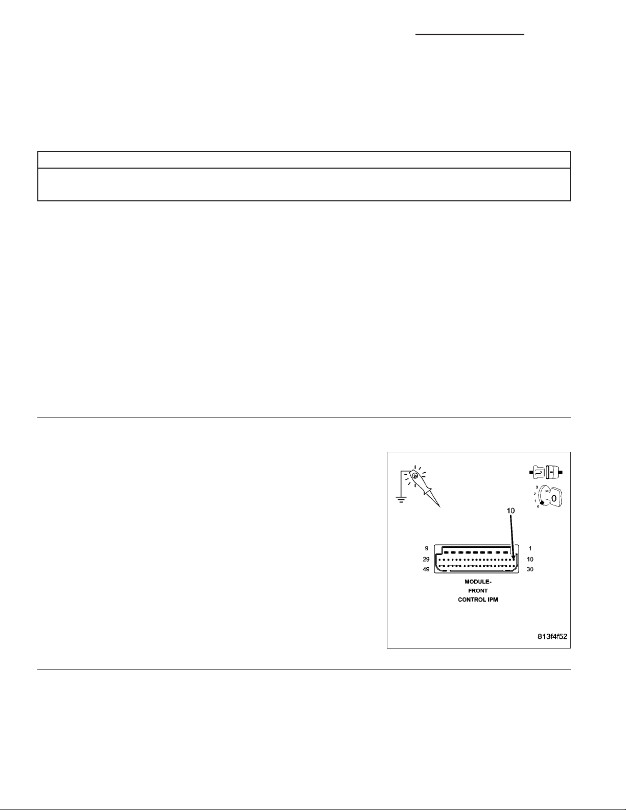
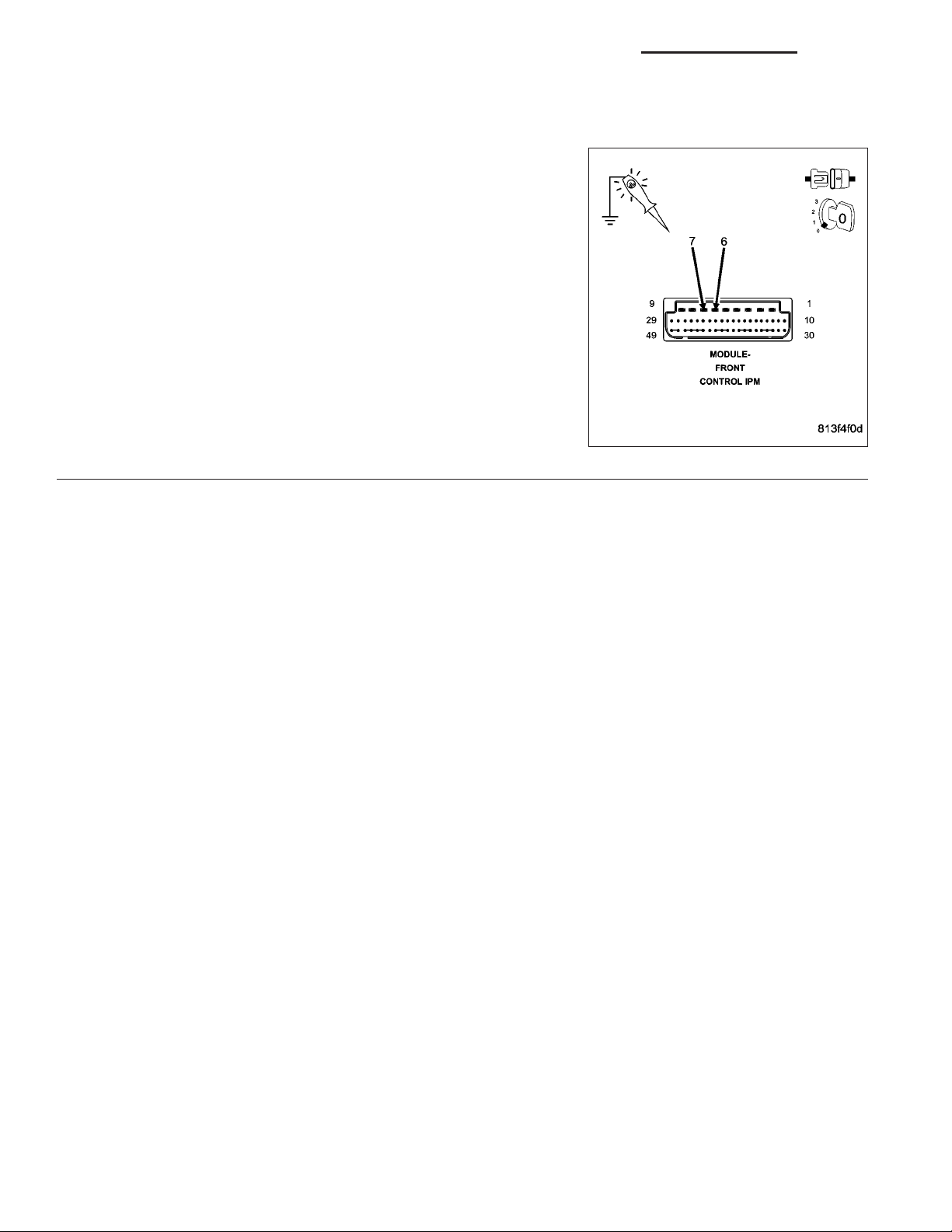
CHECK THE FUSED B+ CIRCUIT
2.
Turn the ignition off.
Remove the FCM from the IPM.
Using a 12-volt test light connected to ground, probe the Fused B+ cir-
cuit (cavity 10).
Is the test light illuminated?
Yes >>
No >>
Go To 2
The condition that set this DTC is no longer present. Using the wiring diagram/schematic as a guide,
inspect the wiring for chafed, pierced, pinched, and partially broken wires and the wiring harness connectors for broken, bent, pushed out, and corroded terminals.
Replace the Front Control Module in accordance with the
service information.
Perform BODY VERIFICATION TEST - VER 1. (Refer to
BODY VERIFICATION TEST - VER 1.)
Replace the Power Distribution Center in accordance with
the service information.
Perform BODY VERIFICATION TEST - VER 1. (Refer to
BODY VERIFICATION TEST - VER 1.)
Page 5
DR/DH ELECTRONIC CONTROL MODULES - ELECTRICAL DIAGNOSTICS 8E - 5
BATTERY 1 VOLTAGE OPEN (FCM)
Page 6

8E - 6 ELECTRONIC CONTROL MODULES - ELECTRICAL DIAGNOSTICS DR/DH
BATTERY 1 VOLTAGE OPEN (FCM) (CONTINUED)
For a complete wiring diagram Refer to Section 8W.
• When Monitored:
With the ignition on.
• Set Condition:
The FCM detects low voltage on battery input 1.
Possible Causes
FUSE #13
POWER DISTRIBUTION CENTER
FRONT CONTROL MODULE
Diagnostic Test
CHECK FOR AN ACTIVE DTC
1.
Turn the ignition on.
With the DRB, erase the FCM DTC’s.
Turn the ignition off then turn the ignition on and wait approximately 1 minute.
With the DRB, read the FCM DTC’s.
Did this DTC reset?
Yes >>
No >>
CHECK FUSE #13
2.
Turn the ignition off.
Check fuse #13 in the IPM.
Is the fuse open?
Yes >>
No >>
Go To 2
The condition that set this DTC is no longer present. Using the wiring diagram/schematic as a guide,
inspect the wiring for chafed, pierced, pinched, and partially broken wires and the wiring harness connectors for broken, bent, pushed out, and corroded terminals.
Replace the fuse and check for a possible intermittent short to ground condition.
Perform BODY VERIFICATION TEST - VER 1. (Refer to BODY VERIFICATION TEST - VER 1.)
Go To 3
Page 7
DR/DH ELECTRONIC CONTROL MODULES - ELECTRICAL DIAGNOSTICS 8E - 7
BATTERY 1 VOLTAGE OPEN (FCM) (CONTINUED)
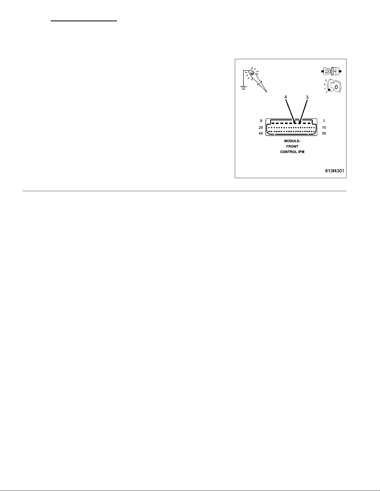
CHECK THE FUSED B+ CIRCUITS
3.
Remove the FCM from the IPM.
NOTE: Ensure fuse #13 is installed in the IPM.
Using a 12-volt test light connected to ground, probe both Fused B+
circuits (cavities 3 and 4).
Is the test light illuminated for both circuits?
Yes >>
No >>
Replace the Front Control Module in accordance with the
service information.
Perform BODY VERIFICATION TEST - VER 1. (Refer to
BODY VERIFICATION TEST - VER 1.)
Replace the Power Distribution Center in accordance with
the service information.
Perform BODY VERIFICATION TEST - VER 1. (Refer to
BODY VERIFICATION TEST - VER 1.)
Page 8
8E - 8 ELECTRONIC CONTROL MODULES - ELECTRICAL DIAGNOSTICS DR/DH
BATTERY 2 VOLTAGE OPEN (FCM)
Page 9

DR/DH ELECTRONIC CONTROL MODULES - ELECTRICAL DIAGNOSTICS 8E - 9
BATTERY 2 VOLTAGE OPEN (FCM) (CONTINUED)
For a complete wiring diagram Refer to Section 8W.
• When Monitored:
With the ignition on.
• Set Condition:
The FCM detects low voltage on battery input 2.
Possible Causes
FUSE #11
POWER DISTRIBUTION CENTER
FRONT CONTROL MODULE
Diagnostic Test
CHECK FOR AN ACTIVE DTC
1.
Turn the ignition on.
With the DRB, erase the FCM DTC’s.
Turn the ignition off then turn the ignition on and wait approximately 1 minute.
With the DRB, read the FCM DTC’s.
Did this DTC reset?
Yes >>
No >>
CHECK FUSE #11
2.
Turn the ignition off.
Check fuse #11 in the IPM.
Is the fuse open?
Yes >>
No >>
Go To 2
The condition that set this DTC is no longer present. Using the wiring diagram/schematic as a guide,
inspect the wiring for chafed, pierced, pinched, and partially broken wires and the wiring harness connectors for broken, bent, pushed out, and corroded terminals.
Replace the fuse and check for a possible intermittent short to ground condition.
Perform BODY VERIFICATION TEST - VER 1. (Refer to BODY VERIFICATION TEST - VER 1.)
Go To 3
Page 10
8E - 10 ELECTRONIC CONTROL MODULES - ELECTRICAL DIAGNOSTICS DR/DH
BATTERY 2 VOLTAGE OPEN (FCM) (CONTINUED)
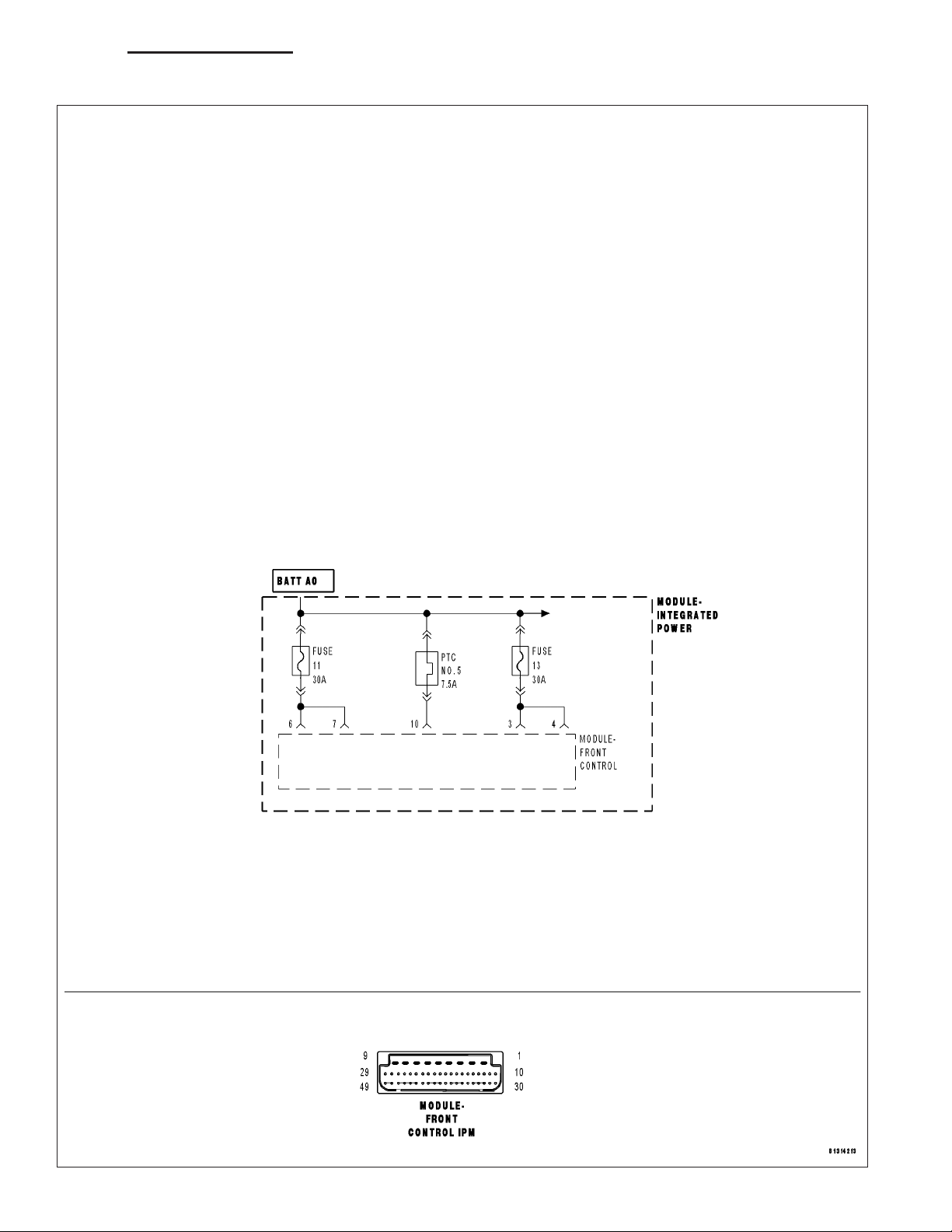
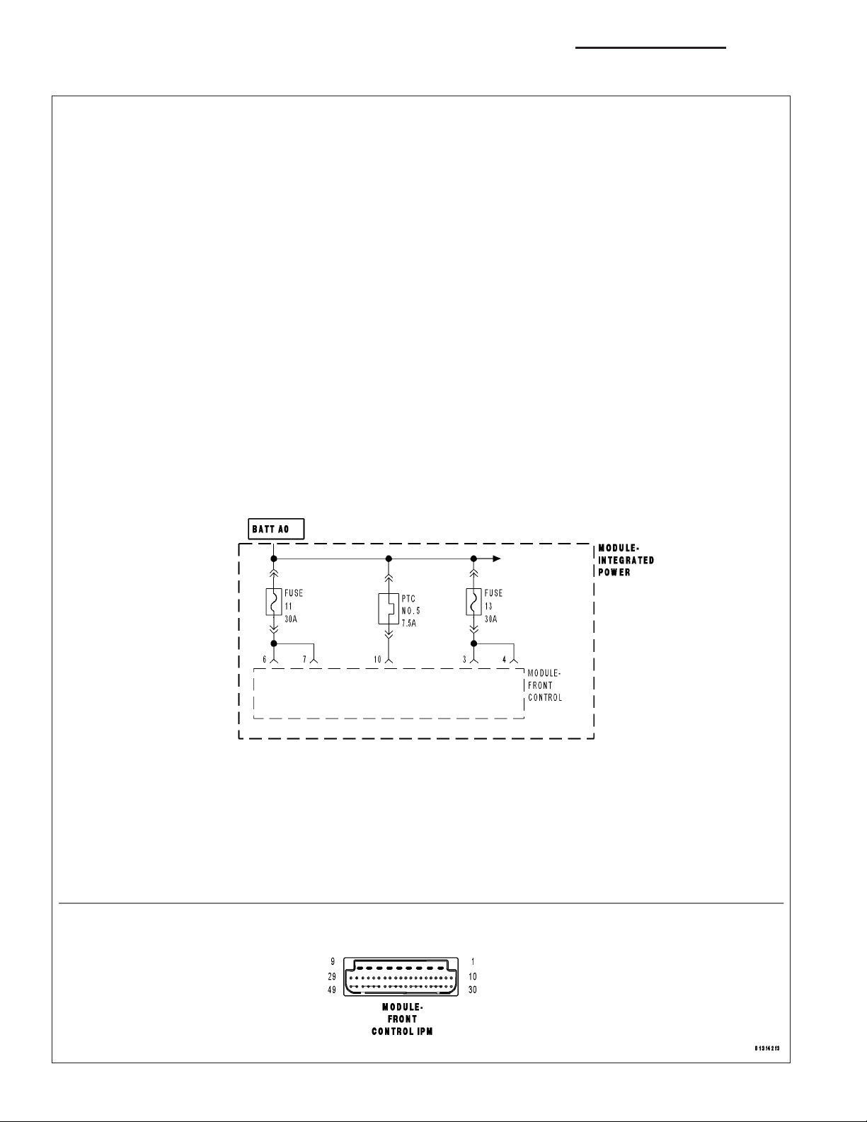
CHECK THE FUSED B+ CIRCUITS
3.
Remove the FCM from the IPM.
NOTE: Ensure fuse #11 is installed in the IPM.
Using a 12-volt test light connected to ground, probe both Fused B+
circuits (cavities 6 and 7).
Is the test light illuminated for both circuits?
Yes >>
No >>
Replace the Front Control Module in accordance with the
service information.
Perform BODY VERIFICATION TEST - VER 1. (Refer to
BODY VERIFICATION TEST - VER 1.)
Replace the Power Distribution Center in accordance with
the service information.
Perform BODY VERIFICATION TEST - VER 1. (Refer to
BODY VERIFICATION TEST - VER 1.)
Page 11

DR/DH ELECTRONIC CONTROL MODULES - ELECTRICAL DIAGNOSTICS 8E - 11
BUS SHORTED TO BATTERY (FCM)
For a complete wiring diagram Refer to Section 8W.
• When Monitored:
Continuously
• Set Condition:
Anytime the FCM detects a short to battery on the PCI Bus circuit.
Possible Causes
INTERMITTENT SHORT TO BATTERY ON THE (D25) PCI BUS CIRCUIT
Diagnostic Test
INTERMITTENT CONDITION
1.
NOTE: For this code to be active, the DRB will not be able to communicate with any modules on the vehicle
(except the PCM/ECM).
NOTE: Clear the code. If this code continues to set and the DRB can still communicate with the FCM, it will
be necessary to replace the FCM.
WARNING: WHEN THE ENGINE IS OPERATING, DO NOT STAND IN A DIRECT LINE WITH THE FAN. DO NOT
PUT YOUR HANDS NEAR THE PULLEYS, BELTS OR FAN. DO NOT WEAR LOOSE CLOTHING.
NOTE: The conditions that set the DTC are not present at this time. The following list may help in identifying the intermittent condition.
With the engine running at normal operating temperature, wiggle the wiring harnesses. This is to try and duplicate
the complete bus failure condition.
Refer to any Technical Service Bulletins (TSB) that may apply.
Visually inspect the related wiring harness. Look for any chafed, pierced, pinched, or partially broken wires.
Visually inspect the related wiring harness connectors. Look for broken, bent, pushed out, or corroded terminals.
Were any of the above conditions present?
Yes >>
No >>
Repair as necessary.
Perform BODY VERIFICATION TEST - VER 1. (Refer to BODY VERIFICATION TEST - VER 1.)
Test Complete.
Page 12

8E - 12 ELECTRONIC CONTROL MODULES - ELECTRICAL DIAGNOSTICS DR/DH
BUS SHORTED TO GROUND (FCM)
For a complete wiring diagram Refer to Section 8W.
• When Monitored:
Continuously
• Set Condition:
Anytime the FCM detects a short to ground on the PCI Bus circuit.
Possible Causes
INTERMITTENT SHORT TO GROUND ON THE (D25) PCI BUS CIRCUIT
Diagnostic Test
INTERMITTENT CONDITION
1.
NOTE: For this code to be active, the DRB will not be able to communicate with any modules on the vehicle
(except the PCM/ECM).
NOTE: Clear the code. If this code continues to set and the DRB can still communicate with the FCM, it will
be necessary to replace the FCM.
WARNING: WHEN THE ENGINE IS OPERATING, DO NOT STAND IN A DIRECT LINE WITH THE FAN. DO NOT
PUT YOUR HANDS NEAR THE PULLEYS, BELTS OR FAN. DO NOT WEAR LOOSE CLOTHING.
NOTE: The conditions that set the DTC are not present at this time. The following list may help in identifying the intermittent condition.
With the engine running at normal operating temperature, wiggle the wiring harnesses. This is to try and duplicate
the complete bus failure condition.
Refer to any Technical Service Bulletins (TSB) that may apply.
Visually inspect the related wiring harness. Look for any chafed, pierced, pinched, or partially broken wires.
Visually inspect the related wiring harness connectors. Look for broken, bent, pushed out, or corroded terminals.
Were any of the above conditions present?
Yes >>
No >>
Repair as necessary.
Perform BODY VERIFICATION TEST - VER 1. (Refer to BODY VERIFICATION TEST - VER 1.)
Test Complete.
Page 13

DR/DH ELECTRONIC CONTROL MODULES - ELECTRICAL DIAGNOSTICS 8E - 13
EEPROM CHECKSUM FAILURE (FCM)
For a complete wiring diagram Refer to Section 8W.
• When Monitored:
Continuously
• Set Condition:
When the EEPROM memory checksum is determined to be incorrect.
Possible Causes
FRONT CONTROL MODULE
Diagnostic Test
ACTIVE DTC
1.
Turn the ignition on.
With the DRB, erase the FCM DTC’s.
Turn the ignition off then turn the ignition on and wait approximately 1 minute.
With the DRB, read the FCM DTC’s.
Did this DTC reset?
Yes >>
No >>
Replace the Front Control Module in accordance with the service information.
Perform BODY VERIFICATION TEST - VER 1. (Refer to BODY VERIFICATION TEST - VER 1.)
Test Complete.
Page 14

8E - 14 ELECTRONIC CONTROL MODULES - ELECTRICAL DIAGNOSTICS DR/DH
INTERNAL BOOTLOADER CHECKSUM FAILURE (FCM)
For a complete wiring diagram Refer to Section 8W.
• When Monitored:
Continuously
• Set Condition:
When the bootloader checksum is determined to be incorrect.
Possible Causes
FRONT CONTROL MODULE
Diagnostic Test
ACTIVE DTC
1.
Turn the ignition on.
With the DRB, erase the FCM DTC’s.
Turn the ignition off then turn the ignition on and wait approximately 1 minute.
With the DRB, read the FCM DTC’s.
Did this DTC reset?
Yes >>
No >>
Replace the Front Control Module in accordance with the service information.
Perform BODY VERIFICATION TEST - VER 1. (Refer to BODY VERIFICATION TEST - VER 1.)
Test Complete.
Page 15

DR/DH ELECTRONIC CONTROL MODULES - ELECTRICAL DIAGNOSTICS 8E - 15
INTERNAL FLASH MEMORY CHECKSUM FAILURE (FCM)
For a complete wiring diagram Refer to Section 8W.
• When Monitored:
Continuously
• Set Condition:
When the flash memory checksum is determined to be incorrect.
Possible Causes
FRONT CONTROL MODULE
Diagnostic Test
ACTIVE DTC
1.
Turn the ignition on.
With the DRB, erase the FCM DTC’s.
Turn the ignition off then turn the ignition on and wait approximately 1 minute.
With the DRB, read the FCM DTC’s.
Did this DTC reset?
Yes >>
No >>
Replace the Front Control Module in accordance with the service information.
Perform BODY VERIFICATION TEST - VER 1. (Refer to BODY VERIFICATION TEST - VER 1.)
Test Complete.
Page 16

8E - 16 ELECTRONIC CONTROL MODULES - ELECTRICAL DIAGNOSTICS DR/DH
MIC MESSAGES NOT RECEIVED (FCM)
For a complete wiring diagram Refer to Section 8W.
• When Monitored:
With the ignition on.
• Set Condition:
The FCM does not receive any messages from the MIC for at least 5 seconds.
Possible Causes
(D25) PCI BUS CIRCUIT OPEN
INSTRUMENT CLUSTER POWER AND GROUND
FRONT CONTROL MODULE
Diagnostic Test
ATTEMPT TO COMMUNICATE WITH THE INSTRUMENT CLUSTER (MIC)
1.
Turn the ignition on.
With the DRB, enter Body then Electro/Mech Cluster.
Was the DRB able to I/D or communicate with the Instrument Cluster (MIC)?
Yes >>
No >>
FRONT CONTROL MODULE
2.
With the DRB, erase DTC’s.
Turn the ignition on and wait approximately 1 minute.
With the DRB, read DTC’s.
Did this DTC reset?
Yes >>
No >>
Go To 2
Refer to the table of contents and perform the related symptom.
Perform BODY VERIFICATION TEST - VER 1. (Refer to BODY VERIFICATION TEST - VER 1.)
Replace the Front Control Module in accordance with the service information.
Perform BODY VERIFICATION TEST - VER 1. (Refer to BODY VERIFICATION TEST - VER 1.)
The condition that set this DTC is no longer present. Using the wiring diagram/schematic as a guide,
inspect the wiring for chafed, pierced, pinched, and partially broken wires and the wiring harness connectors for broken, bent, pushed out, and corroded terminals.
Page 17

DR/DH ELECTRONIC CONTROL MODULES - ELECTRICAL DIAGNOSTICS 8E - 17
PCI BUS INTERNAL - LOOPBACK FAILURE (FCM)
For a complete wiring diagram Refer to Section 8W.
• When Monitored:
Continuously
• Set Condition:
When the loopback test has failed.
Possible Causes
FRONT CONTROL MODULE
Diagnostic Test
ACTIVE DTC
1.
Turn the ignition on.
With the DRB, erase the FCM DTC’s.
Turn the ignition off then turn the ignition on and wait approximately 1 minute.
With the DRB, read the FCM DTC’s.
Did this DTC reset?
Yes >>
No >>
Replace the Front Control Module in accordance with the service information.
Perform BODY VERIFICATION TEST - VER 1. (Refer to BODY VERIFICATION TEST - VER 1.)
Test Complete.
Page 18

8E - 18 ELECTRONIC CONTROL MODULES - ELECTRICAL DIAGNOSTICS DR/DH
PCM MESSAGES NOT RECEIVED (FCM)
For a complete wiring diagram Refer to Section 8W.
• When Monitored:
With the ignition on.
• Set Condition:
The FCM does not receive any messages from the PCM for at least 5 seconds.
Possible Causes
(D25) PCI BUS CIRCUIT OPEN
POWERTRAIN CONTROL MODULE POWER AND GROUND
FRONT CONTROL MODULE
Diagnostic Test
CHECK THE STATUS OF THE PCM ON THE PCI BUS NETWORK
1.
Turn the ignition on.
With the DRB, enter System Monitors then J1850 Module Scan.
Is the PCM active on the bus?
Yes >>
No >>
ATTEMPT TO COMMUNICATE WITH THE PCM
2.
With the DRB, attempt to communicate with the PCM.
Was the DRB able to communicate with the PCM?
Yes >>
No >>
Erase the DTC, if the DTC resets replace the Front Control Module in accordance with the service information.
Perform BODY VERIFICATION TEST - VER 1. (Refer to BODY VERIFICATION TEST - VER 1.)
Go To 2
Go To 3
Refer to the table of contents and perform the related symptom.
Perform BODY VERIFICATION TEST - VER 1. (Refer to BODY VERIFICATION TEST - VER 1.)
Page 19
DR/DH ELECTRONIC CONTROL MODULES - ELECTRICAL DIAGNOSTICS 8E - 19
PCM MESSAGES NOT RECEIVED (FCM) (CONTINUED)
CHECK THE (D25) PCI BUS CIRCUIT FOR AN OPEN
3.
Turn the ignition off.
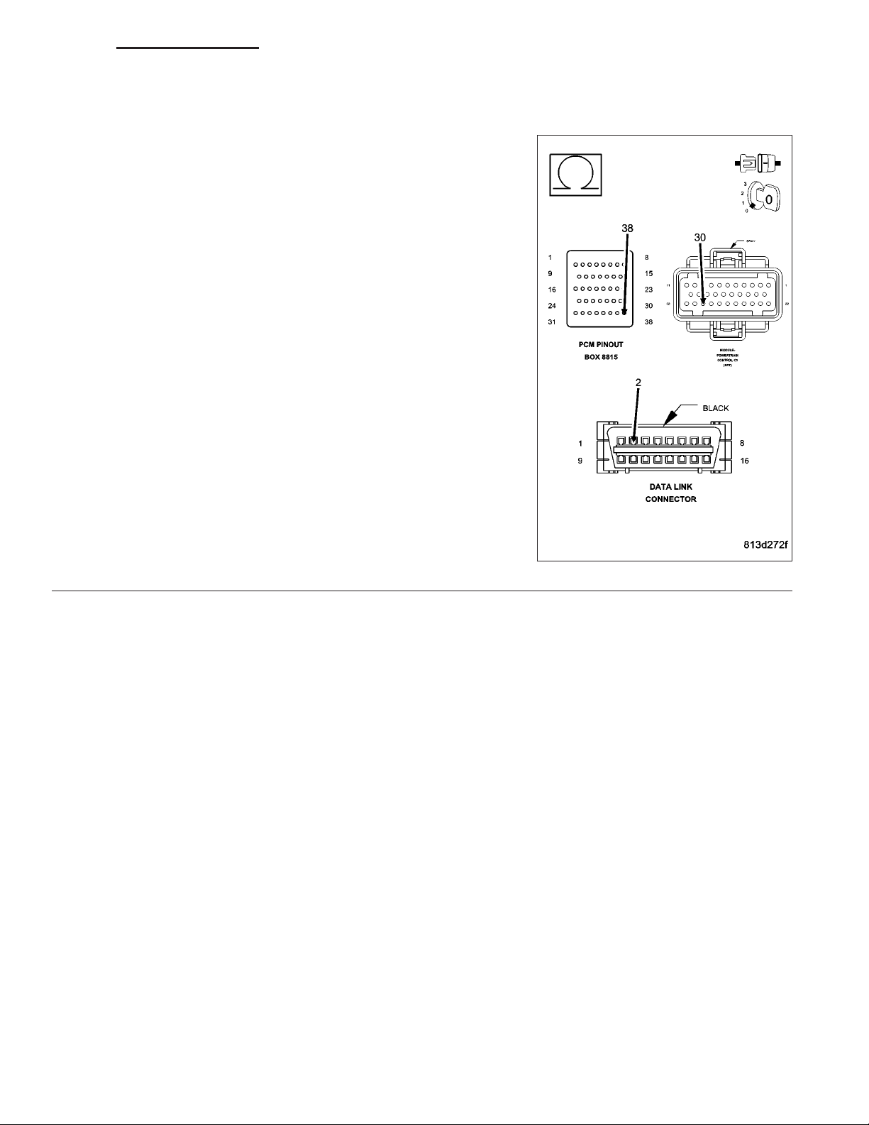
Disconnect the PCM harness connector.
CAUTION: If the vehicle is equipped with an NGC controller, do
not probe the PCM harness connectors. Probing the PCM harness connectors will damage the PCM terminals resulting in poor
terminal to pin connection. Install miller special tool #8815 to perform diagnosis.
Disconnect the DRB from the DLC.
Measure the resistance of the PCI Bus circuit between the PCM con-
nector (from special tool #8815 if NGC) and the DLC.
Is the resistance below 5.0 ohms?
Yes >>
No >>
Replace and program the PCM in accordance with the
service information.
Perform the appropriate VERIFICATION TEST.
Repair the PCI Bus circuit for an open.
Perform BODY VERIFICATION TEST - VER 1. (Refer to
BODY VERIFICATION TEST - VER 1.)
Page 20

8E - 20 ELECTRONIC CONTROL MODULES - ELECTRICAL DIAGNOSTICS DR/DH
VIN NOT LEARNED CORRECTLY (FCM)
For a complete wiring diagram Refer to Section 8W.
• When Monitored:
With the ignition on.
• Set Condition:
The VIN is programmed into the FCM via a PCI bus message from the PCM/ECM. When learning the VIN, the
FCM computes a check digit to verify that the VIN learned was valid. If not valid, the DTC will set and the VIN
will not be learned.
Possible Causes
FRONT CONTROL MODULE
Diagnostic Test
ACTIVE DTC
1.
Turn the ignition on.
With the DRB, erase the FCM DTC’s.
Turn the ignition off then turn the ignition on and wait approximately 1 minute.
With the DRB, read the FCM DTC’s.
Did this DTC reset?
Yes >>
No >>
Replace the Front Control Module in accordance with the service information.
Perform BODY VERIFICATION TEST - VER 1. (Refer to BODY VERIFICATION TEST - VER 1.)
Test Complete.
Page 21
DR/DH ELECTRONIC CONTROL MODULES - ELECTRICAL DIAGNOSTICS 8E - 21
*NO RESPONSE FROM ANTILOCK BRAKE MODULE
Page 22
8E - 22 ELECTRONIC CONTROL MODULES - ELECTRICAL DIAGNOSTICS DR/DH
*NO RESPONSE FROM ANTILOCK BRAKE MODULE (CONTINUED)
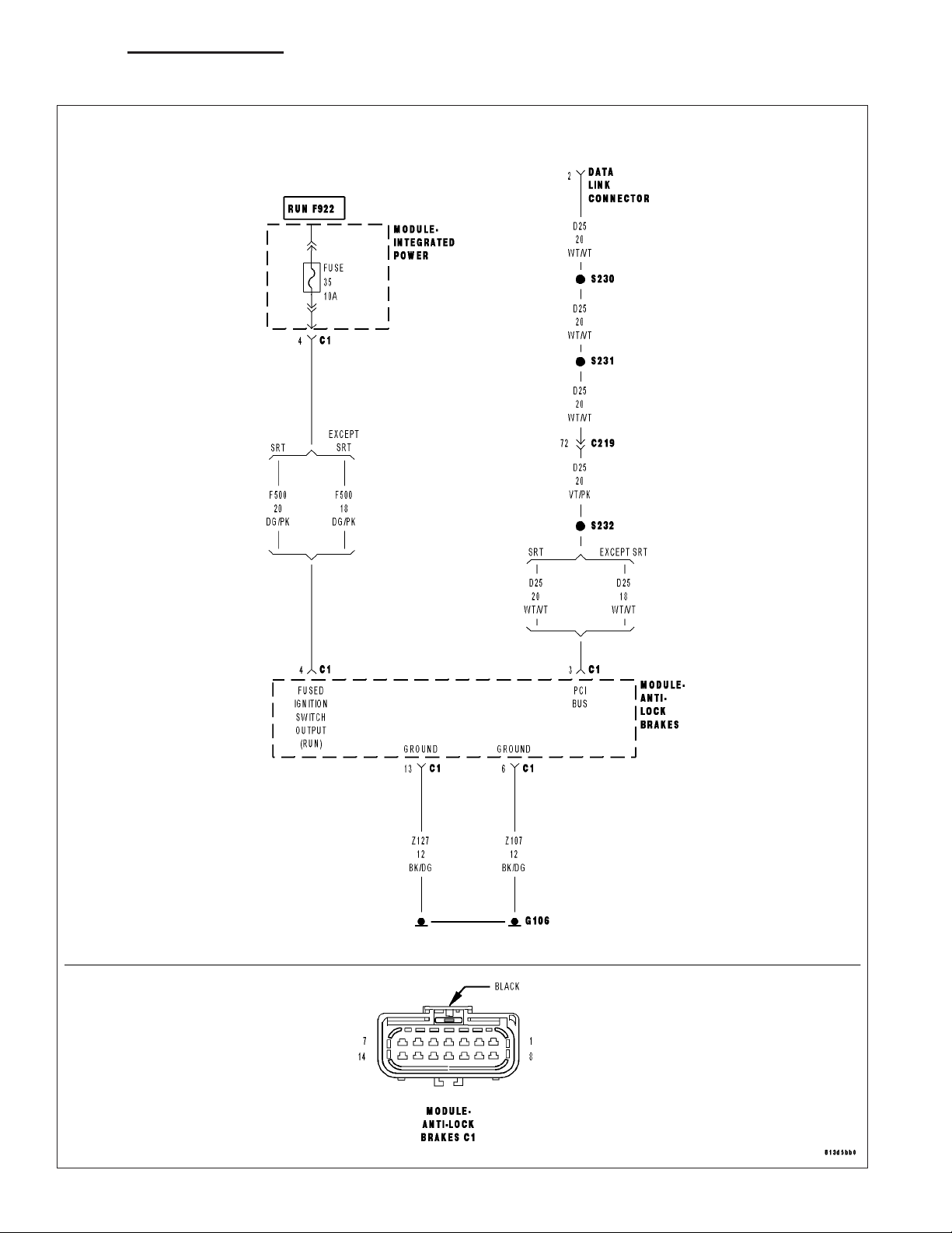
For a complete wiring diagram Refer to Section 8W.
Possible Causes
(Z107) (Z127) GROUND CIRCUIT OPEN
(F500) FUSED IGNITION SWITCH OUTPUT CIRCUIT OPEN
(D25) PCI BUS CIRCUIT OPEN
ANTILOCK BRAKE MODULE
Diagnostic Test
ESTABLISH COMMUNICATIONS WITH OTHER PCI BUS MODULES
1.
Turn the ignition on.
NOTE: As soon as one or more modules communicates with the DRB, answer the question.
NOTE: Ensure there is PCI bus communication with other modules. If not, refer to the PCI Bus Communi-
cation Failure symptom and repair as necessary.
With the DRB, attempt to communicate with the ORC.
With the DRB, attempt to communicate with the Instrument Cluster.
Was the DRB able to I/D or communicate with either of the modules?
Yes >>
No >>
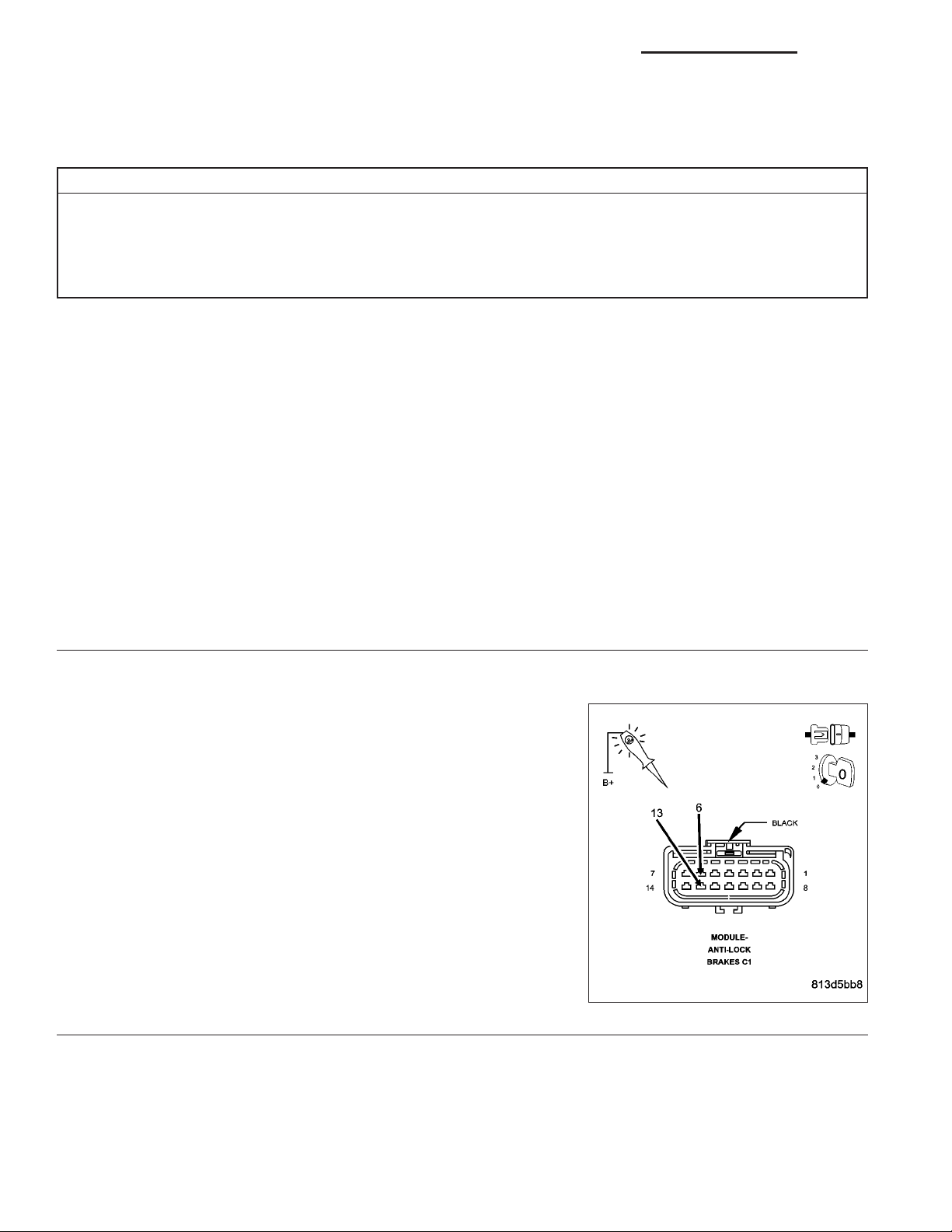
(Z107) (Z127) GROUND CIRCUIT OPEN
2.
Turn the ignition off.
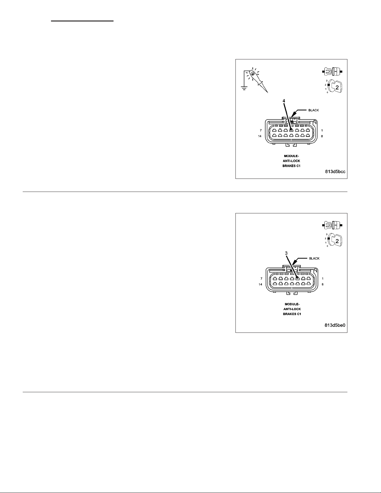
Disconnect the Antilock Brake Module C1 harness connector.
Using a 12-volt test light connected to 12-volts, probe each (Z107)
(Z127, if equipped) ground circuit.
Is the test light illuminated for each circuit?
Yes >>
No >>
Go To 2
Refer to the table of contents and perform the related symptom.
Perform ABS VERIFICATION TEST - VER 1.
Go To 3
Repair the (Z107) or (Z127) Ground circuit for an open.
Perform ABS VERIFICATION TEST - VER 1.
Page 23
DR/DH ELECTRONIC CONTROL MODULES - ELECTRICAL DIAGNOSTICS 8E - 23
*NO RESPONSE FROM ANTILOCK BRAKE MODULE (CONTINUED)
(F500) FUSED IGNITION SWITCH OUTPUT CIRCUIT OPEN
3.
Turn the ignition on.
Using a 12-volt test light connected to ground, probe the (F500) Fused
Ignition Switch Output circuit.
Is the test light illuminated?
Yes >>
No >>
(D25) PCI BUS CIRCUIT OPEN
4.
Use Scope input cable CH7058, Cable to Probe adapter CH7062, and
the red and black test probes.
Connect the scope input cable to the channel one connector on the
DRB. Attach the red and black leads and the cable to probe adapter to
the scope input cable.
With the DRBIIIT select Pep Module Tools.
Select lab scope.
Select Live Data.
Select 12 volt square wave.
Press F2 for Scope.
Press F2 and use the down arrow to set voltage range to 20 volts.
Press F2 again when complete.
Connect the Black lead to the chassis ground. Connect the Red lead
to the PCI Bus circuit in the Antilock Brake Module connector.
Observe the voltage display on the DRB Lab Scope.
Go To 4
Repair the (F500) Fused Ignition Switch Output circuit for
an open.
Perform ABS VERIFICATION TEST - VER 1.
Does the voltage pulse from 0 to approximately 7.5 volts?
Yes >>
No >>
Replace the Antilock Brake Module in accordance with the service information.
Perform ABS VERIFICATION TEST - VER 1.
Repair the (D25) PCI Bus circuit for an open.
Perform ABS VERIFICATION TEST - VER 1.
Page 24
8E - 24 ELECTRONIC CONTROL MODULES - ELECTRICAL DIAGNOSTICS DR/DH
*NO RESPONSE FROM AMPLIFIER
Page 25
DR/DH ELECTRONIC CONTROL MODULES - ELECTRICAL DIAGNOSTICS 8E - 25
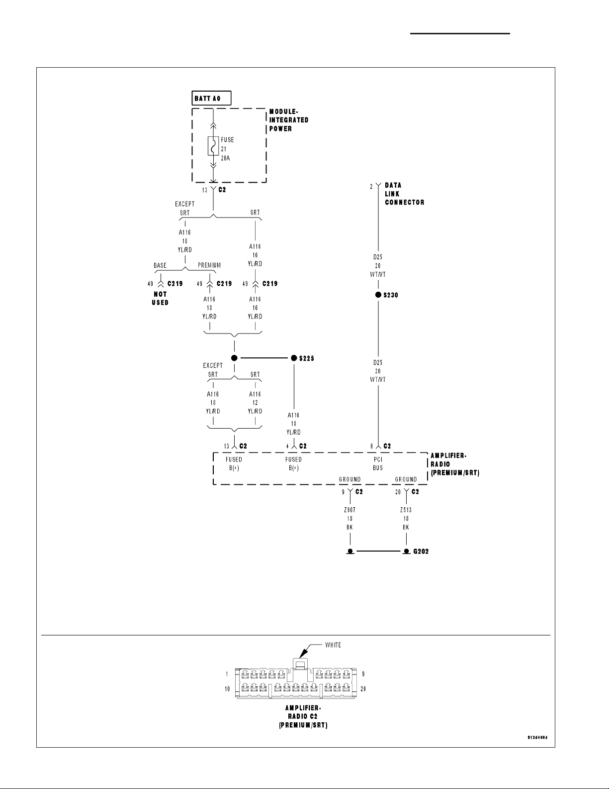
*NO RESPONSE FROM AMPLIFIER (CONTINUED)
For a complete wiring diagram Refer to Section 8W.
Possible Causes
(Z513) (Z907) GROUND CIRCUIT OPEN
(A116) FUSED B+ CIRCUIT OPEN
(D25) PCI BUS CIRCUIT OPEN
AMPLIFIER
Diagnostic Test
ESTABLISH COMMUNICATIONS WITH THE RADIO
1.
Turn the ignition on.
NOTE: Ensure there is PCI bus communication with other modules. If not, refer to the PCI Bus Communication Failure symptom and repair as necessary.
NOTE: The radio must be turned on for the DRB to get a response from the amplifier.
With the DRB, attempt to communicate with the radio.
Was the DRB able to I/D or communicate with the radio?
Yes >>
No >>
(Z513) (Z907) GROUND CIRCUIT OPEN
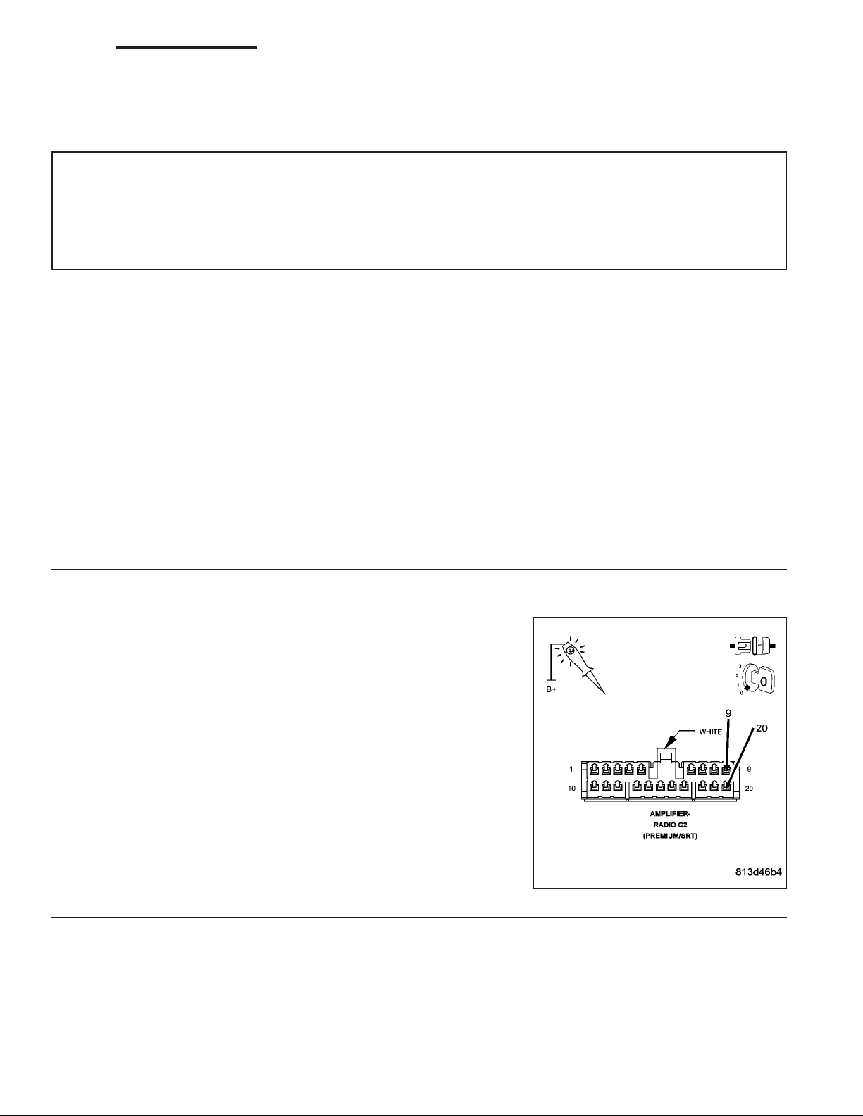
2.
Turn the ignition off.
Disconnect the Amplifier C2 harness connector.
Using a 12-volt test light connected to 12-volts, probe each (Z513)
(Z907) ground circuit.
Is the test light illuminated for each circuit?
Yes >>
No >>
Go To 2
Refer to the table of contents and perform the related symptom.
Perform BODY VERIFICATION TEST - VER 1. (Refer to BODY VERIFICATION TEST - VER 1.)
Go To 3
Repair the (Z513) or (Z907) Ground circuit for an open.
Perform BODY VERIFICATION TEST - VER 1. (Refer to
BODY VERIFICATION TEST - VER 1.)
Page 26
8E - 26 ELECTRONIC CONTROL MODULES - ELECTRICAL DIAGNOSTICS DR/DH
*NO RESPONSE FROM AMPLIFIER (CONTINUED)
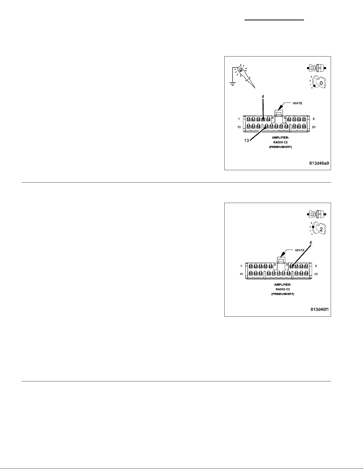
(A116) FUSED B+ CIRCUIT OPEN
3.
Using a 12-volt test light connected to ground, probe each (A116)
Fused B+ circuit.
Is the test light illuminated for each circuit?
Yes >>
No >>
(D25) PCI BUS CIRCUIT OPEN
4.
Turn the ignition on.
Use Scope input cable CH7058, Cable to Probe adapter CH7062, and
the red and black test probes.
Connect the scope input cable to the channel one connector on the
DRB. Attach the red and black leads and the cable to probe adapter to
the scope input cable.
With the DRBIIIT select Pep Module Tools.
Select lab scope.
Select Live Data.
Select 12 volt square wave.
Press F2 for Scope.
Press F2 and use the down arrow to set voltage range to 20 volts.
Press F2 again when complete.
Connect the Black lead to the chassis ground. Connect the Red lead
to the PCI Bus circuit in the Amplifier connector.
Observe the voltage display on the DRB Lab Scope.
Go To 4
Repair the (A116) Fused B+ circuit for an open.
Perform BODY VERIFICATION TEST - VER 1. (Refer to
BODY VERIFICATION TEST - VER 1.)
Does the voltage pulse from 0 to approximately 7.5 volts?
Yes >>
No >>
Replace the Amplifier in accordance with the service information.
Perform BODY VERIFICATION TEST - VER 1. (Refer to BODY VERIFICATION TEST - VER 1.)
Repair the (D25) PCI Bus circuit for an open.
Perform BODY VERIFICATION TEST - VER 1. (Refer to BODY VERIFICATION TEST - VER 1.)
Page 27
DR/DH ELECTRONIC CONTROL MODULES - ELECTRICAL DIAGNOSTICS 8E - 27
*NO RESPONSE FROM CLUSTER
Page 28
8E - 28 ELECTRONIC CONTROL MODULES - ELECTRICAL DIAGNOSTICS DR/DH
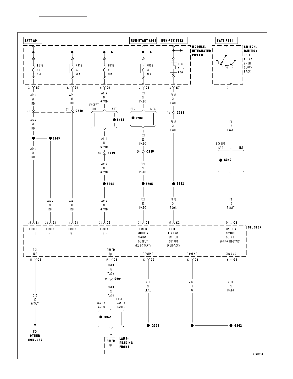
*NO RESPONSE FROM CLUSTER (CONTINUED)
For a complete wiring diagram Refer to Section 8W.
Possible Causes
(Z921) (Z108) (Z18) GROUND CIRCUIT OPEN
(A944) (M288) (A941) (A114) FUSED B+ CIRCUIT OPEN
(F21) (F1) (F983) FUSED IGNITION SWITCH OUTPUT CIRCUIT OPEN
(D25) PCI BUS CIRCUIT OPEN
CLUSTER
Diagnostic Test
ESTABLISH COMMUNICATIONS WITH OTHER PCI BUS MODULES
1.
Turn the ignition on.
NOTE: Ensure there is PCI bus communication with other modules. If not, refer to the PCI Bus Communication Failure symptom and repair as necessary.
With the DRB, attempt to communicate with the ORC.
With the DRB, attempt to communicate with the ABS.
Was the DRB able to I/D or communicate with either module?
Yes >>
No >>
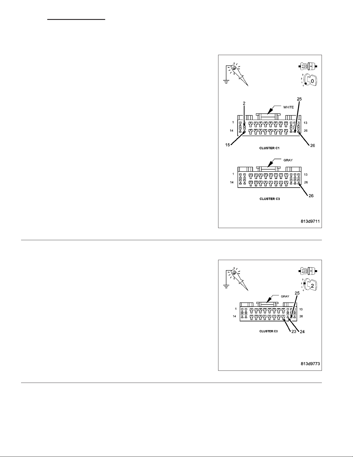
(Z921) (Z108) (Z18) GROUND CIRCUIT OPEN
2.
Turn the ignition off.
Disconnect the Cluster harness connectors.
Using a 12-volt test light connected to 12-volts, probe each (Z921)
(Z108) (Z18) ground circuit.
Is the test light illuminated for each circuit?
Yes >>
No >>
Go To 2
Refer to the table of contents and perform the related symptom.
Perform BODY VERIFICATION TEST - VER 1. (Refer to BODY VERIFICATION TEST - VER 1.)
Go To 3
Repair the (Z921) (Z108) (Z18) Ground circuit for an open.
Perform BODY VERIFICATION TEST - VER 1. (Refer to
BODY VERIFICATION TEST - VER 1.)
Page 29
DR/DH ELECTRONIC CONTROL MODULES - ELECTRICAL DIAGNOSTICS 8E - 29
*NO RESPONSE FROM CLUSTER (CONTINUED)
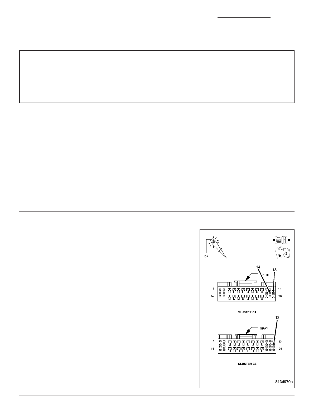
(A944) (M288) (A941) (A114) FUSED B+ CIRCUIT OPEN
3.
Using a 12-volt test light connected to ground, probe each (A944)
(M288) (A941) (A114) Fused B+ circuit.
Is the test light illuminated for each circuit?
Yes >>
No >>
(F21) (F1) (F983) FUSED IGNITION SWITCH OUTPUT CIRCUIT OPEN
4.
Turn the ignition on.
Using a 12-volt test light connected to ground, probe each (F21) (F1)
(F983) Fused Ignition Switch Output circuit.
Go To 4
Repair the (A944) (M288) (A941) (A114) Fused B+ circuit
for an open.
Perform BODY VERIFICATION TEST - VER 1. (Refer to
BODY VERIFICATION TEST - VER 1.)
Is the test light illuminated?
Yes >>
No >>
Go To 5
Repair the (F21) (F1) (F983) Fused Ignition Switch Output
circuit for an open.
Perform BODY VERIFICATION TEST - VER 1. (Refer to
BODY VERIFICATION TEST - VER 1.)
Page 30
8E - 30 ELECTRONIC CONTROL MODULES - ELECTRICAL DIAGNOSTICS DR/DH
*NO RESPONSE FROM CLUSTER (CONTINUED)
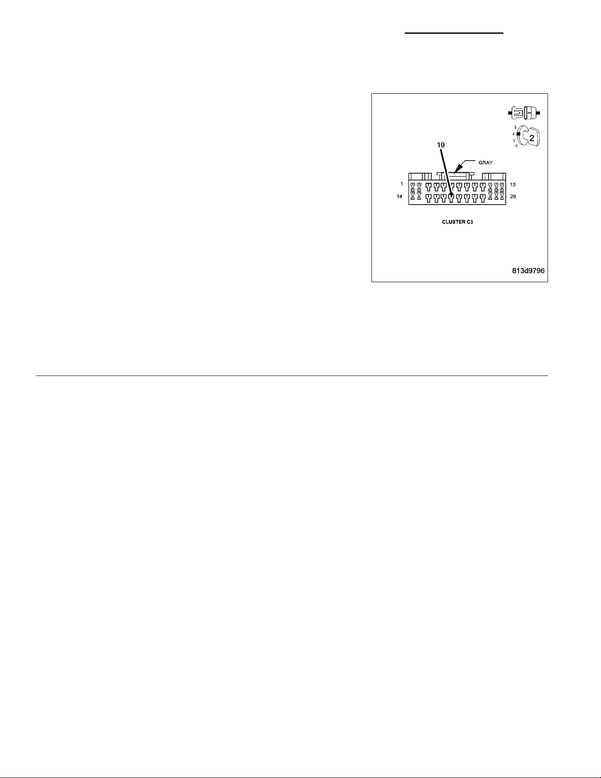
(D25) PCI BUS CIRCUIT OPEN
5.
Use Scope input cable CH7058, Cable to Probe adapter CH7062, and
the red and black test probes.
Connect the scope input cable to the channel one connector on the
DRB. Attach the red and black leads and the cable to probe adapter to
the scope input cable.
With the DRBIIIT select Pep Module Tools.
Select lab scope.
Select Live Data.
Select 12 volt square wave.
Press F2 for Scope.
Press F2 and use the down arrow to set voltage range to 20 volts.
Press F2 again when complete.
Connect the Black lead to the chassis ground. Connect the Red lead
to the PCI Bus circuit in the Cluster connector.
Observe the voltage display on the DRB Lab Scope.
Does the voltage pulse from 0 to approximately 7.5 volts?
Yes >>
No >>
Replace the Cluster in accordance with the service information.
Perform BODY VERIFICATION TEST - VER 1. (Refer to BODY VERIFICATION TEST - VER 1.)
Repair the (D25) PCI Bus circuit for an open.
Perform BODY VERIFICATION TEST - VER 1. (Refer to BODY VERIFICATION TEST - VER 1.)
Page 31

DR/DH ELECTRONIC CONTROL MODULES - ELECTRICAL DIAGNOSTICS 8E - 31
*NO RESPONSE FROM ENGINE CONTROL MODULE (PCI BUS) - DIESEL
Page 32

8E - 32 ELECTRONIC CONTROL MODULES - ELECTRICAL DIAGNOSTICS DR/DH
*NO RESPONSE FROM ENGINE CONTROL MODULE (PCI BUS) - DIESEL (CONTINUED)
For a complete wiring diagram Refer to Section 8W.
Possible Causes
ENGINE CONTROL MODULE POWER AND GROUND
(D25) PCI BUS CIRCUIT OPEN
ENGINE CONTROL MODULE
Diagnostic Test
ESTABLISH COMMUNICATIONS WITH OTHER PCI BUS MODULES
1.
Turn the ignition on.
NOTE: Ensure there is PCI bus communication with other modules. If not, refer to the PCI Bus Communication Failure symptom and repair as necessary.
NOTE: As soon as one or more modules communicates with the DRB, answer the question.
With the DRB, attempt to communicate with the ORC.
With the DRB, attempt to communicate with the Instrument Cluster.
Was the DRB able to I/D or communicate with either of the modules?
Yes >>
No >>
Go To 2
Refer to the table of contents and perform the related symptom.
Perform POWERTRAIN VERIFICATION TEST - VER 1 (DIESEL).
Page 33

DR/DH ELECTRONIC CONTROL MODULES - ELECTRICAL DIAGNOSTICS 8E - 33
*NO RESPONSE FROM ENGINE CONTROL MODULE (PCI BUS) - DIESEL (CONTINUED)
(D25) PCI BUS CIRCUIT OPEN
2.
With the DRB, read Engine Control Module DTC’s. This is to ensure
power and ground to the ECM are operational.
NOTE: If the DRB will not read ECM DTC’s, follow the NO
RESPONSE TO ECM (SCI ONLY) symptom.
NOTE: If the vehicle will not start and the DRB displays a no
response message, refer to the appropriate symptom in the
Engine Electrical Diagnostics - Diesel category.
Turn the ignition off.
Disconnect the Engine Control Module C2 harness connector.
Turn the ignition on.
Use Scope input cable CH7058, Cable to Probe adapter CH7062, and
the red and black test probes.
Connect the scope input cable to the channel one connector on the
DRB. Attach the red and black leads and the cable to probe adapter to
the scope input cable.
With the DRBIIIT select Pep Module Tools.
Select lab scope.
Select Live Data.
Select 12 volt square wave.
Press F2 for Scope.
Press F2 and use the down arrow to set voltage range to 20 volts. Press F2 again when complete.
Connect the Black lead to the chassis ground. Connect the Red lead to the PCI Bus circuit in the Engine Control
Module connector.
Observe the voltage display on the DRB Lab Scope.
Does the voltage pulse from 0 to approximately 7.5 volts?
Yes >>
No >>
Replace the Engine Control Module in accordance with the service information.
Perform POWERTRAIN VERIFICATION TEST - VER 1 (DIESEL).
Repair the (D25) PCI Bus circuit for an open.
Perform POWERTRAIN VERIFICATION TEST - VER 1 (DIESEL).
Page 34

8E - 34 ELECTRONIC CONTROL MODULES - ELECTRICAL DIAGNOSTICS DR/DH
*NO RESPONSE FROM ENGINE CONTROL MODULE (SCI ONLY) - DIESEL
Page 35

DR/DH ELECTRONIC CONTROL MODULES - ELECTRICAL DIAGNOSTICS 8E - 35
*NO RESPONSE FROM ENGINE CONTROL MODULE (SCI ONLY) - DIESEL (CONTINUED)
For a complete wiring diagram Refer to Section 8W.
Possible Causes
(D21) SCI TRANSMIT CIRCUIT SHORTED TO GROUND
(D20) SCI RECEIVE CIRCUIT SHORTED TO GROUND
(D21) SCI TRANSMIT CIRCUIT SHORTED TO VOLTAGE
(D20) SCI RECEIVE CIRCUIT SHORTED TO VOLTAGE
(D21) SCI TRANSMIT CIRCUIT OPEN
(D20) SCI RECEIVE CIRCUIT OPEN
(D21) SCI TRANSMIT CIRCUIT SHORTED TO THE (D20) SCI RECEIVE CIRCUIT
ENGINE CONTROL MODULE
Diagnostic Test
CHECK ENGINE CONTROL MODULE POWER AND GROUND
1.
Refer to the Engine Electrical Diagnostics - Diesel and perform the symptom Checking ECM Power and Ground
Circuits.
Did the vehicle pass this test?
Yes >>
No >>
SCI CIRCUITS SHORTED TO GROUND
2.
Turn the ignition off.
Disconnect the DRB from the DLC.
Disconnect the Engine Control Module C2 harness connector.
Measure the resistance between ground and the (D21) SCI Transmit
circuit.
Measure the resistance between ground and the (D20) SCI Receive
circuit.
Is the resistance below 10.0 ohms for either circuit?
Yes >>
No >>
Go To 2
Repair as necessary.
Perform POWERTRAIN VERIFICATION TEST - VER 1 (DIESEL).
Repair the SCI Circuit that measured below 10.0 ohms for
a short to ground.
Perform POWERTRAIN VERIFICATION TEST - VER 1
(DIESEL).
Go To 3
Page 36

8E - 36 ELECTRONIC CONTROL MODULES - ELECTRICAL DIAGNOSTICS DR/DH
*NO RESPONSE FROM ENGINE CONTROL MODULE (SCI ONLY) - DIESEL (CONTINUED)
SCI CIRCUITS SHORTED TO VOLTAGE
3.
Turn the ignition on.
Measure the voltage of the (D21) SCI Transmit circuit.
Measure the voltage of the (D20) SCI Receive circuit.
Is the voltage above 1.0 volt for either circuit?
Yes >>
No >>
(D21) SCI TRANSMIT CIRCUIT OPEN
4.
Turn the ignition off.
Measure the resistance of the (D21) SCI Transmit circuit between the
ECM harness connector and the DLC.
Is the resistance below 5.0 ohms?
Yes >>
No >>
Repair the SCI Circuit that measured above 1.0 volt for a
short to voltage.
Perform POWERTRAIN VERIFICATION TEST - VER 1
(DIESEL).
Go To 4
Go To 5
Repair the (D21) SCI Transmit circuit for an open.
Perform POWERTRAIN VERIFICATION TEST - VER 1
(DIESEL).
Page 37

DR/DH ELECTRONIC CONTROL MODULES - ELECTRICAL DIAGNOSTICS 8E - 37
*NO RESPONSE FROM ENGINE CONTROL MODULE (SCI ONLY) - DIESEL (CONTINUED)
(D20) SCI RECEIVE CIRCUIT OPEN
5.
Measure the resistance of the (D20) SCI Receive circuit between the
ECM harness connector and the DLC.
Is the resistance below 5.0 ohms?
Yes >>
No >>
(D21) SCI TRANSMIT CIRCUIT SHORTED TO THE (D20) SCI RECEIVE CIRCUIT
6.
Measure the resistance between the (D21) SCI Transmit and the
(D20) SCI Receive circuits.
Go To 6
Repair the (D20) SCI Receive circuit for an open.
Perform POWERTRAIN VERIFICATION TEST - VER 1
(DIESEL).
Is the resistance below 5.0 ohms?
Yes >>
No >>
Repair the (D21) SCI Transmit circuit for a short to the
(D20) SCI Receive circuit.
Perform POWERTRAIN VERIFICATION TEST - VER 1
(DIESEL).
Replace the Engine Control Module in accordance with the
service information.
Perform POWERTRAIN VERIFICATION TEST - VER 1
(DIESEL).
Page 38

8E - 38 ELECTRONIC CONTROL MODULES - ELECTRICAL DIAGNOSTICS DR/DH
*NO RESPONSE FROM FRONT CONTROL MODULE
Page 39

DR/DH ELECTRONIC CONTROL MODULES - ELECTRICAL DIAGNOSTICS 8E - 39
*NO RESPONSE FROM FRONT CONTROL MODULE (CONTINUED)
For a complete wiring diagram Refer to Section 8W.
Possible Causes
(Z117) (Z118) GROUND CIRCUIT OPEN
FUSED IGNITION SWITCH OUTPUT CIRCUIT OPEN
(D25) PCI BUS CIRCUIT OPEN
FRONT CONTROL MODULE
Diagnostic Test
ESTABLISH COMMUNICATIONS WITH OTHER PCI BUS MODULES
1.
Turn the ignition on.
NOTE: Check all fuses before beginning.
NOTE: As soon as one or more modules communicates with the DRB, answer the question.
NOTE: Ensure there is PCI bus communication with other modules. If not, refer to the PCI Bus Communi-
cation Failure symptom and repair as necessary.
With the DRB, attempt to communicate with the ORC.
With the DRB, attempt to communicate with the Instrument Cluster.
Was the DRB able to I/D or communicate with either of the modules?
Yes >>
No >>
(Z117) (Z118) GROUND CIRCUIT OPEN
2.
Turn the ignition off.
Remove the Front Control Module from the IPM.
Using a 12-volt test light connected to 12-volts, probe each (Z117) and
(Z118) ground circuits.
Is the test light illuminated for each circuit?
Yes >>
No >>
Go To 2
Refer to the table of contents and perform the related symptom.
Perform BODY VERIFICATION TEST - VER 1. (Refer to BODY VERIFICATION TEST - VER 1.)
Go To 3
Repair the (Z117) or (Z118) Ground circuit for an open
between the IPM connector and the grounding point. If
OK, replace the power distribution center in accordance
with the service information.
Perform BODY VERIFICATION TEST - VER 1. (Refer to
BODY VERIFICATION TEST - VER 1.)
Page 40

8E - 40 ELECTRONIC CONTROL MODULES - ELECTRICAL DIAGNOSTICS DR/DH
*NO RESPONSE FROM FRONT CONTROL MODULE (CONTINUED)
FUSED IGNITION SWITCH OUTPUT CIRCUIT OPEN
3.
Turn the ignition on.
Using a 12-volt test light connected to ground, probe the Fused Igni-
tion Switch Output circuit.
Is the test light illuminated?
Yes >>
No >>
(D25) PCI BUS CIRCUIT OPEN
4.
Use Scope input cable CH7058, Cable to Probe adapter CH7062, and
the red and black test probes.
Connect the scope input cable to the channel one connector on the
DRB. Attach the red and black leads and the cable to probe adapter to
the scope input cable.
With the DRBIIIT select Pep Module Tools.
Select lab scope.
Select Live Data.
Select 12 volt square wave.
Press F2 for Scope.
Press F2 and use the down arrow to set voltage range to 20 volts.
Press F2 again when complete.
Connect the Black lead to the chassis ground. Connect the Red lead
to the PCI Bus circuit in the IPM FCM connector.
Observe the voltage display on the DRB Lab Scope.
Go To 4
Check all IPM fuses. If OK, replace the power distribution
center in accordance with the service information.
Perform BODY VERIFICATION TEST - VER 1. (Refer to
BODY VERIFICATION TEST - VER 1.)
Does the voltage pulse from 0 to approximately 7.5 volts?
Yes >>
No >>
Replace the Front Control Module in accordance with the service information.
Perform BODY VERIFICATION TEST - VER 1. (Refer to BODY VERIFICATION TEST - VER 1.)
Repair the (D25) PCI Bus circuit for an open. If OK, replace the power distribution center in accordance
with the service information.
Perform BODY VERIFICATION TEST - VER 1. (Refer to BODY VERIFICATION TEST - VER 1.)
Page 41

DR/DH ELECTRONIC CONTROL MODULES - ELECTRICAL DIAGNOSTICS 8E - 41
*NO RESPONSE FROM FINAL DRIVE CONTROL MODULE
Page 42

8E - 42 ELECTRONIC CONTROL MODULES - ELECTRICAL DIAGNOSTICS DR/DH
*NO RESPONSE FROM FINAL DRIVE CONTROL MODULE (CONTINUED)
For a complete wiring diagram Refer to Section 8W.
Possible Causes
(Z935) (Z937) GROUND CIRCUIT OPEN
(A34) FUSED B+ CIRCUIT OPEN
(F202) FUSED IGNITION SWITCH OUTPUT CIRCUIT OPEN
(D25) PCI BUS CIRCUIT OPEN
FINAL DRIVE CONTROL MODULE
Diagnostic Test
ESTABLISH COMMUNICATIONS WITH THE INSTRUMENT CLUSTER (MIC)
1.
Turn the ignition on.
NOTE: Ensure there is PCI bus communication with other modules. If not, refer to the PCI Bus Communication Failure symptom and repair as necessary.
With the DRB, attempt to communicate with the MIC.
Was the DRB able to I/D or communicate with the MIC?
Yes >>
No >>
(Z935) (Z937) GROUND CIRCUIT OPEN
2.
Turn the ignition off.
Disconnect the Final Drive Control Module harness connector.
Using a 12-volt test light connected to 12-volts, probe each (Z935) and
(Z937) ground circuit.
Is the test light illuminated for each circuit?
Yes >>
No >>
Go To 2
Refer to the table of contents and perform the related symptom.
Perform FDCM VERIFICATION TEST
Go To 3
Repair the (Z935) or (Z937) Ground circuit for an open.
Perform FDCM VERIFICATION TEST
Page 43

DR/DH ELECTRONIC CONTROL MODULES - ELECTRICAL DIAGNOSTICS 8E - 43
*NO RESPONSE FROM FINAL DRIVE CONTROL MODULE (CONTINUED)
(A34) FUSED B+ CIRCUIT OPEN
3.
Using a 12-volt test light connected to ground, probe the (A34) Fused
B+ circuit.
Is the test light illuminated?
Yes >>
No >>
(F202) FUSED IGNITION SWITCH OUTPUT CIRCUIT OPEN
4.
Turn the ignition on.
Using a 12-volt test light connected to ground, probe the (F202) Fused
Ignition Switch Output circuit.
Is the test light illuminated?
Yes >>
No >>
Go To 4
Repair the (A34) Fused B+ circuit for an open.
Perform FDCM VERIFICATION TEST
Go To 5
Repair the (F202) Fused Ignition Switch Output circuit for
an open.
Perform FDCM VERIFICATION TEST
Page 44

8E - 44 ELECTRONIC CONTROL MODULES - ELECTRICAL DIAGNOSTICS DR/DH
*NO RESPONSE FROM FINAL DRIVE CONTROL MODULE (CONTINUED)
(D25) PCI BUS CIRCUIT OPEN
5.
Use Scope input cable CH7058, Cable to Probe adapter CH7062, and
the red and black test probes.
Connect the scope input cable to the channel one connector on the
DRB. Attach the red and black leads and the cable to probe adapter to
the scope input cable.
With the DRBIIIT select Pep Module Tools.
Select lab scope.
Select Live Data.
Select 12 volt square wave.
Press F2 for Scope.
Press F2 and use the down arrow to set voltage range to 20 volts.
Press F2 again when complete.
Connect the Black lead to the chassis ground. Connect the Red lead
to the PCI Bus circuit in the FDCM connector.
Observe the voltage display on the DRB Lab Scope.
Does the voltage pulse from 0 to approximately 7.5 volts?
Yes >>
No >>
Replace the Final Drive Control Module in accordance with the service information.
Perform FDCM VERIFICATION TEST
Repair the (D25) PCI Bus circuit for an open.
Perform FDCM VERIFICATION TEST
Page 45

DR/DH ELECTRONIC CONTROL MODULES - ELECTRICAL DIAGNOSTICS 8E - 45
*NO RESPONSE FROM HANDS FREE MODULE
Page 46

8E - 46 ELECTRONIC CONTROL MODULES - ELECTRICAL DIAGNOSTICS DR/DH
*NO RESPONSE FROM HANDS FREE MODULE (CONTINUED)
For a complete wiring diagram Refer to Section 8W.
Possible Causes
(Z970) GROUND CIRCUIT OPEN
(A114) FUSED B+ CIRCUIT OPEN
(F983) FUSED IGNITION SWITCH OUTPUT CIRCUIT OPEN
(D25) PCI BUS CIRCUIT OPEN
HANDS FREE MODULE
Diagnostic Test
ESTABLISH COMMUNICATIONS WITH THE INSTRUMENT CLUSTER (MIC)
1.
Turn the ignition on.
NOTE: Ensure there is PCI bus communication with other modules. If not, refer to the PCI Bus Communication Failure symptom and repair as necessary.
With the DRB, attempt to communicate with the MIC.
Was the DRB able to I/D or communicate with the MIC?
Yes >>
No >>
(Z970) GROUND CIRCUIT OPEN
2.
Turn the ignition off.
Disconnect the Hands Free Module C1 harness connector.
Using a 12-volt test light connected to 12-volts, probe the (Z970)
ground circuit.
Is the test light illuminated?
Yes >>
No >>
Go To 2
Refer to the table of contents and perform the related symptom.
Perform BODY VERIFICATION TEST - VER 1. (Refer to BODY VERIFICATION TEST - VER 1.)
Go To 3
Repair the (Z970) Ground circuit for an open.
Perform BODY VERIFICATION TEST - VER 1. (Refer to
BODY VERIFICATION TEST - VER 1.)
Page 47

DR/DH ELECTRONIC CONTROL MODULES - ELECTRICAL DIAGNOSTICS 8E - 47
*NO RESPONSE FROM HANDS FREE MODULE (CONTINUED)
(A114) FUSED B+ CIRCUIT OPEN
3.
Using a 12-volt test light connected to ground, probe the (A114) Fused
B+ circuit.
Is the test light illuminated?
Yes >>
No >>
(F983) FUSED IGNITION SWITCH OUTPUT CIRCUIT OPEN
4.
Turn the ignition on.
Using a 12-volt test light connected to ground, probe the (F983) Fused
Ignition Switch Output circuit.
Is the test light illuminated?
Yes >>
No >>
Go To 4
Repair the (A114) Fused B+ circuit for an open.
Perform BODY VERIFICATION TEST - VER 1. (Refer to
BODY VERIFICATION TEST - VER 1.)
Go To 5
Repair the (F983) Fused Ignition Switch Output circuit for
an open.
Perform BODY VERIFICATION TEST - VER 1. (Refer to
BODY VERIFICATION TEST - VER 1.)
Page 48

8E - 48 ELECTRONIC CONTROL MODULES - ELECTRICAL DIAGNOSTICS DR/DH
*NO RESPONSE FROM HANDS FREE MODULE (CONTINUED)
(D25) PCI BUS CIRCUIT OPEN
5.
Use Scope input cable CH7058, Cable to Probe adapter CH7062, and
the red and black test probes.
Connect the scope input cable to the channel one connector on the
DRB. Attach the red and black leads and the cable to probe adapter to
the scope input cable.
With the DRBIIIT select Pep Module Tools.
Select lab scope.
Select Live Data.
Select 12 volt square wave.
Press F2 for Scope.
Press F2 and use the down arrow to set voltage range to 20 volts.
Press F2 again when complete.
Connect the Black lead to the chassis ground. Connect the Red lead
to the PCI Bus circuit in the HFM connector.
Observe the voltage display on the DRB Lab Scope.
Does the voltage pulse from 0 to approximately 7.5 volts?
Yes >>
No >>
Replace the Hands Free Module in accordance with the service information.
Perform BODY VERIFICATION TEST - VER 1. (Refer to BODY VERIFICATION TEST - VER 1.)
Repair the (D25) PCI Bus circuit for an open.
Perform BODY VERIFICATION TEST - VER 1. (Refer to BODY VERIFICATION TEST - VER 1.)
Page 49

DR/DH ELECTRONIC CONTROL MODULES - ELECTRICAL DIAGNOSTICS 8E - 49
*NO RESPONSE FROM HVAC
Page 50

8E - 50 ELECTRONIC CONTROL MODULES - ELECTRICAL DIAGNOSTICS DR/DH
*NO RESPONSE FROM HVAC (CONTINUED)
For a complete wiring diagram Refer to Section 8W.
Possible Causes
(Z24) GROUND CIRCUIT OPEN
(F504) FUSED IGNITION SWITCH OUTPUT CIRCUIT OPEN
(D25) PCI BUS CIRCUIT OPEN
A/C HEATER CONTROL
Diagnostic Test
ESTABLISH COMMUNICATIONS WITH OTHER PCI BUS MODULES
1.
Turn the ignition on.
NOTE: As soon as one or more modules communicates with the DRB, answer the question.
NOTE: Ensure there is PCI bus communication with other modules. If not, refer to the PCI Bus Communi-
cation Failure symptom and repair as necessary.
With the DRB, attempt to communicate with the ORC.
With the DRB, attempt to communicate with the Instrument Cluster.
Was the DRB able to I/D or communicate with either of the modules?
Yes >>
No >>
(Z24) GROUND CIRCUIT OPEN
2.
Turn the ignition off.
Disconnect the A/C Heater Control C1 harness connector.
Using a 12-volt test light connected to 12-volts, probe the (Z24)
ground circuit.
Is the test light illuminated?
Yes >>
No >>
Go To 2
Refer to the table of contents and perform the related symptom.
Perform BODY VERIFICATION TEST - VER 1. (Refer to BODY VERIFICATION TEST - VER 1.)
Go To 3
Repair the (Z24) Ground circuit for an open.
Perform BODY VERIFICATION TEST - VER 1. (Refer to
BODY VERIFICATION TEST - VER 1.)
Page 51

DR/DH ELECTRONIC CONTROL MODULES - ELECTRICAL DIAGNOSTICS 8E - 51
*NO RESPONSE FROM HVAC (CONTINUED)
(F504) FUSED IGNITION SWITCH OUTPUT CIRCUIT OPEN
3.
Turn the ignition on.
Using a 12-volt test light connected to ground, probe the (F504) Fused
Ignition Switch Output circuit.
Is the test light illuminated?
Yes >>
No >>
(D25) PCI BUS CIRCUIT OPEN
4.
Use Scope input cable CH7058, Cable to Probe adapter CH7062, and
the red and black test probes.
Connect the scope input cable to the channel one connector on the
DRB. Attach the red and black leads and the cable to probe adapter to
the scope input cable.
With the DRBIIIT select Pep Module Tools.
Select lab scope.
Select Live Data.
Select 12 volt square wave.
Press F2 for Scope.
Press F2 and use the down arrow to set voltage range to 20 volts.
Press F2 again when complete.
Connect the Black lead to the chassis ground. Connect the Red lead
to the PCI Bus circuit in the A/C Heater Control connector.
Observe the voltage display on the DRB Lab Scope.
Go To 4
Repair the (F504) Fused Ignition Switch Output circuit for
an open.
Perform BODY VERIFICATION TEST - VER 1. (Refer to
BODY VERIFICATION TEST - VER 1.)
Does the voltage pulse from 0 to approximately 7.5 volts?
Yes >>
No >>
Replace the A/C Heater Control in accordance with the service information.
Perform BODY VERIFICATION TEST - VER 1. (Refer to BODY VERIFICATION TEST - VER 1.)
Repair the (D25) PCI Bus circuit for an open.
Perform BODY VERIFICATION TEST - VER 1. (Refer to BODY VERIFICATION TEST - VER 1.)
Page 52

8E - 52 ELECTRONIC CONTROL MODULES - ELECTRICAL DIAGNOSTICS DR/DH
*NO RESPONSE FROM OCCUPANT RESTRAINT CONTROL MODULE
Page 53

DR/DH ELECTRONIC CONTROL MODULES - ELECTRICAL DIAGNOSTICS 8E - 53
*NO RESPONSE FROM OCCUPANT RESTRAINT CONTROL MODULE (CONTINUED)
For a complete wiring diagram Refer to Section 8W.
Possible Causes
(F201) FUSED IGNITION SWITCH OUTPUT (RUN-START) CIRCUIT OPEN
(F100) FUSED IGNITION SWITCH OUTPUT (RUN) CIRCUIT OPEN
(Z104) GROUND CIRCUIT OPEN
(D25) PCI BUS CIRCUIT OPEN
OCCUPANT RESTRAINT CONTROL MODULE
Diagnostic Test
CHECKING FOR VOLTAGE AT ORC
1.
NOTE: Ensure that the battery is fully charged.
NOTE: Ensure there is PCI bus communication with other mod-
ules. If not, refer to the PCI Bus Communication Failure symptom
and repair as necessary.
WARNING: TO AVOID PERSONAL INJURY OR DEATH, TURN THE
IGNITION OFF, DISCONNECT THE BATTERY AND WAIT TWO MINUTES BEFORE PROCEEDING.
Disconnect the ORC harness connectors.
Connect the appropriate Load Tool ORC Adapter to the ORC connec-
tor.
Turn the ignition on and then reconnect the Battery.
Using a 12-volt test light connected to ground, probe the (F100) Fused
Ignition Switch Output (Run) Circuit and the (F201) Fused Ignition
Switch Output (Run-Start) Circuit.
NOTE: One open circuit will not cause a NO RESPONSE condition.
Is the test light illuminated on both circuits?
Yes >>
No >>
Go To 2
Repair the (F100) Fused Ignition Switch Output (Run) and (F201) Fused Ignition Switch Output (Run/
Start) circuits for an open.
Perform AIRBAG VERIFICATION TEST - VER 1.
Page 54

8E - 54 ELECTRONIC CONTROL MODULES - ELECTRICAL DIAGNOSTICS DR/DH
*NO RESPONSE FROM OCCUPANT RESTRAINT CONTROL MODULE (CONTINUED)
(Z104) GROUND CIRCUIT OPEN
2.
Turn the ignition off.
Using a 12-volt test light connected to 12-volts, probe the (Z104)
ground circuit.
Is the test light illuminated?
Yes >>
No >>
(D25) PCI BUS CIRCUIT OPEN
3.
Turn the ignition on.
Use Scope input cable CH7058, Cable to Probe adapter CH7062, and
the red and black test probes.
Connect the scope input cable to the channel one connector on the
DRB. Attach the red and black leads and the cable to probe adapter to
the scope input cable.
With the DRBIIIT select Pep Module Tools.
Select lab scope.
Select Live Data.
Select 12 volt square wave.
Press F2 for Scope.
Press F2 and use the down arrow to set voltage range to 20 volts.
Press F2 again when complete.
Connect the Black lead to the chassis ground. Connect the Red lead
to the PCI Bus circuit in the ORC connector.
Observe the voltage display on the DRB Lab Scope.
Go To 3
Repair the (Z104) Ground circuit for an open.
Perform AIRBAG VERIFICATION TEST - VER 1.
Does the voltage pulse from 0 to approximately 7.5 volts?
Yes >>
No >>
Replace the Occupant Restraint Control Module in accordance with the service information.
Perform AIRBAG VERIFICATION TEST - VER 1.
Repair the (D25) PCI Bus circuit for an open.
Perform AIRBAG VERIFICATION TEST - VER 1.
Page 55

DR/DH ELECTRONIC CONTROL MODULES - ELECTRICAL DIAGNOSTICS 8E - 55
*NO RESPONSE FROM OVERHEAD CONSOLE
Page 56

8E - 56 ELECTRONIC CONTROL MODULES - ELECTRICAL DIAGNOSTICS DR/DH
*NO RESPONSE FROM OVERHEAD CONSOLE (CONTINUED)
For a complete wiring diagram Refer to Section 8W.
Possible Causes
(Z13) GROUND CIRCUIT OPEN
(A919) FUSED B+ CIRCUIT OPEN
(F21) FUSED IGNITION SWITCH OUTPUT CIRCUIT OPEN
(D25) PCI BUS CIRCUIT OPEN
ELECTRONIC OVERHEAD MODULE
Diagnostic Test
ESTABLISH COMMUNICATIONS WITH THE INSTRUMENT CLUSTER (MIC)
1.
Turn the ignition on.
NOTE: Ensure there is PCI bus communication with other modules. If not, refer to the PCI Bus Communication Failure symptom and repair as necessary.
With the DRB, attempt to communicate with the MIC.
Was the DRB able to I/D or communicate with the MIC?
Yes >>
No >>
(Z13) GROUND CIRCUIT OPEN
2.
Turn the ignition off.
Disconnect the Electronic Overhead Module harness connector.
Using a 12-volt test light connected to 12-volts, probe the (Z13)
ground circuit.
Is the test light illuminated?
Yes >>
No >>
Go To 2
Refer to the table of contents and perform the related symptom.
Perform BODY VERIFICATION TEST - VER 1. (Refer to BODY VERIFICATION TEST - VER 1.)
Go To 3
Repair the (Z13) Ground circuit for an open.
Perform BODY VERIFICATION TEST - VER 1. (Refer to
BODY VERIFICATION TEST - VER 1.)
Page 57

DR/DH ELECTRONIC CONTROL MODULES - ELECTRICAL DIAGNOSTICS 8E - 57
*NO RESPONSE FROM OVERHEAD CONSOLE (CONTINUED)
(A919) FUSED B+ CIRCUIT OPEN
3.
Using a 12-volt test light connected to ground, probe the (A919) Fused
B+ circuit.
Is the test light illuminated?
Yes >>
No >>
(F21) FUSED IGNITION SWITCH OUTPUT CIRCUIT OPEN
4.
Turn the ignition on.
Using a 12-volt test light connected to ground, probe the (F21) Fused
Ignition Switch Output circuit.
Is the test light illuminated?
Yes >>
No >>
Go To 4
Repair the (A919) Fused B+ circuit for an open.
Perform BODY VERIFICATION TEST - VER 1. (Refer to
BODY VERIFICATION TEST - VER 1.)
Go To 5
Repair the (F21) Fused Ignition Switch Output circuit for
an open.
Perform BODY VERIFICATION TEST - VER 1. (Refer to
BODY VERIFICATION TEST - VER 1.)
Page 58

8E - 58 ELECTRONIC CONTROL MODULES - ELECTRICAL DIAGNOSTICS DR/DH
*NO RESPONSE FROM OVERHEAD CONSOLE (CONTINUED)
(D25) PCI BUS CIRCUIT OPEN
5.
Use Scope input cable CH7058, Cable to Probe adapter CH7062, and
the red and black test probes.
Connect the scope input cable to the channel one connector on the
DRB. Attach the red and black leads and the cable to probe adapter to
the scope input cable.
With the DRBIIIT select Pep Module Tools.
Select lab scope.
Select Live Data.
Select 12 volt square wave.
Press F2 for Scope.
Press F2 and use the down arrow to set voltage range to 20 volts.
Press F2 again when complete.
Connect the Black lead to the chassis ground. Connect the Red lead
to the PCI Bus circuit in the Electronic Overhead Module connector.
Observe the voltage display on the DRB Lab Scope.
Does the voltage pulse from 0 to approximately 7.5 volts?
Yes >>
No >>
Replace the Electronic Overhead Module in accordance with the service information.
Perform BODY VERIFICATION TEST - VER 1. (Refer to BODY VERIFICATION TEST - VER 1.)
Repair the (D25) PCI Bus circuit for an open.
Perform BODY VERIFICATION TEST - VER 1. (Refer to BODY VERIFICATION TEST - VER 1.)
Page 59

DR/DH ELECTRONIC CONTROL MODULES - ELECTRICAL DIAGNOSTICS 8E - 59
*NO RESPONSE FROM PCM (PCI BUS) - JTEC
Page 60

8E - 60 ELECTRONIC CONTROL MODULES - ELECTRICAL DIAGNOSTICS DR/DH
*NO RESPONSE FROM PCM (PCI BUS) - JTEC (CONTINUED)
For a complete wiring diagram Refer to Section 8W.
Possible Causes
POWERTRAIN CONTROL MODULE POWER AND GROUND
(D25) PCI BUS CIRCUIT OPEN
POWERTRAIN CONTROL MODULE
Diagnostic Test
ESTABLISH COMMUNICATIONS WITH OTHER PCI BUS MODULES
1.
Turn the ignition on.
NOTE: Ensure there is PCI bus communication with other modules. If not, refer to the PCI Bus Communication Failure symptom and repair as necessary.
NOTE: As soon as one or more modules communicates with the DRB, answer the question.
With the DRB, attempt to communicate with the ORC.
With the DRB, attempt to communicate with the Instrument Cluster.
Was the DRB able to I/D or communicate with either of the modules?
Yes >>
No >>
Go To 2
Refer to the table of contents and perform the related symptom.
Perform POWERTRAIN VERIFICATION TEST - VER 1.
Page 61

DR/DH ELECTRONIC CONTROL MODULES - ELECTRICAL DIAGNOSTICS 8E - 61
*NO RESPONSE FROM PCM (PCI BUS) - JTEC (CONTINUED)
(D25) PCI BUS CIRCUIT OPEN
2.
With the DRB, read PCM DTC’s. This is to ensure power and ground
to the PCM are operational.
NOTE: If the DRB will not read PCM DTC’s, follow the NO
RESPONSE TO PCM (SCI ONLY) - JTEC symptom.
NOTE: If the vehicle will not start and the DRB displays a no
response message, refer to the appropriate symptom in the
Engine Electrical Diagnostics category.
Turn the ignition off.
Disconnect the PCM C3 harness connector.
Turn the ignition on.
Use Scope input cable CH7058, Cable to Probe adapter CH7062, and
the red and black test probes.
Connect the scope input cable to the channel one connector on the
DRB. Attach the red and black leads and the cable to probe adapter to
the scope input cable.
With the DRBIIIT select Pep Module Tools.
Select lab scope.
Select Live Data.
Select 12 volt square wave.
Press F2 for Scope.
Press F2 and use the down arrow to set voltage range to 20 volts. Press F2 again when complete.
Connect the Black lead to the chassis ground. Connect the Red lead to the PCI Bus circuit in the PCM connector.
Observe the voltage display on the DRB Lab Scope.
Does the voltage pulse from 0 to approximately 7.5 volts?
Yes >>
No >>
Replace the Powertrain Control Module in accordance with the service information.
Perform POWERTRAIN VERIFICATION TEST - VER 1.
Repair the (D25) PCI Bus circuit for an open.
Perform POWERTRAIN VERIFICATION TEST - VER 1.
Page 62

8E - 62 ELECTRONIC CONTROL MODULES - ELECTRICAL DIAGNOSTICS DR/DH
*NO RESPONSE FROM PCM (SCI ONLY) - JTEC
Page 63

DR/DH ELECTRONIC CONTROL MODULES - ELECTRICAL DIAGNOSTICS 8E - 63
*NO RESPONSE FROM PCM (SCI ONLY) - JTEC (CONTINUED)
For a complete wiring diagram Refer to Section 8W.
Possible Causes
(D21) SCI TRANSMIT (PCM) CIRCUIT SHORTED TO GROUND
(D20) SCI RECEIVE (PCM) CIRCUIT SHORTED TO GROUND
(D21) SCI TRANSMIT (PCM) CIRCUIT SHORTED TO VOLTAGE
(D20) SCI RECEIVE (PCM) CIRCUIT SHORTED TO VOLTAGE
(D21) SCI TRANSMIT (PCM) CIRCUIT OPEN
(D20) SCI RECEIVE (PCM) CIRCUIT OPEN
(D21) SCI TRANSMIT (PCM) CIRCUIT SHORTED TO THE (D20) SCI RECEIVE (PCM) CIRCUIT
POWERTRAIN CONTROL MODULE
Diagnostic Test
CHECK POWERTRAIN CONTROL MODULE POWER AND GROUND
1.
Refer to the Engine Electrical Diagnostics and perform the symptom Checking PCM Power and Ground Circuits.
NOTE: With the DRB in the generic scan tool mode, attempt to communicate with the PCM. If the DRB can
communicate with the PCM in the generic scan tool mode, it may not be necessary to perform this step.
Did the vehicle pass this test?
Yes >>
No >>
SCI CIRCUITS SHORTED TO GROUND
2.
Turn the ignition off.
Disconnect the DRB from the DLC.
Disconnect the Powertrain Control Module C3 harness connector.
Measure the resistance between ground and the (D21) SCI Transmit
(PCM) circuit.
Measure the resistance between ground and the (D20) SCI Receive
(PCM) circuit.
Is the resistance below 10.0 ohms for either circuit?
Yes >>
No >>
Go To 2
Repair as necessary.
Perform POWERTRAIN VERIFICATION TEST - VER 1.
Repair the SCI Circuit that measured below 10.0 ohms for
a short to ground.
Perform POWERTRAIN VERIFICATION TEST - VER 1.
Go To 3
Page 64

8E - 64 ELECTRONIC CONTROL MODULES - ELECTRICAL DIAGNOSTICS DR/DH
*NO RESPONSE FROM PCM (SCI ONLY) - JTEC (CONTINUED)
SCI CIRCUITS SHORTED TO VOLTAGE
3.
Turn the ignition on.
Measure the voltage of the (D21) SCI Transmit (PCM) circuit.
Measure the voltage of the (D20) SCI Receive (PCM) circuit.
Is the voltage above 1.0 volt for either circuit?
Yes >>
No >>
(D21) SCI TRANSMIT (PCM) CIRCUIT OPEN
4.
Turn the ignition off.
Measure the resistance of the (D21) SCI Transmit (PCM) circuit
between the DLC and the PCM connector.
Is the resistance below 5.0 ohms?
Yes >>
No >>
Repair the SCI Circuit that measured above 1.0 volt for a
short to voltage.
Perform POWERTRAIN VERIFICATION TEST - VER 1.
Go To 4
Go To 5
Repair the (D21) SCI Transmit (PCM) circuit for an open.
Perform POWERTRAIN VERIFICATION TEST - VER 1.
Page 65

DR/DH ELECTRONIC CONTROL MODULES - ELECTRICAL DIAGNOSTICS 8E - 65
*NO RESPONSE FROM PCM (SCI ONLY) - JTEC (CONTINUED)
(D20) SCI RECEIVE (PCM) CIRCUIT OPEN
5.
Measure the resistance of the (D20) SCI Receive (PCM) circuit
between the DLC and the PCM connector.
Is the resistance below 5.0 ohms?
Yes >>
No >>
(D21) SCI TRANSMIT (PCM) CIRCUIT SHORTED TO THE (D20) SCI RECEIVE (PCM) CIRCUIT
6.
Measure the resistance between the (D21) SCI Transmit (PCM) and
the (D20) SCI Receive (PCM) circuits.
Go To 6
Repair the (D20) SCI Receive (PCM) circuit for an open.
Perform POWERTRAIN VERIFICATION TEST - VER 1.
Is the resistance below 5.0 ohms?
Yes >>
No >>
Repair the (D21) SCI Transmit (PCM) circuit for a short to
the (D20) SCI Receive (PCM) circuit.
Perform POWERTRAIN VERIFICATION TEST - VER 1.
Replace the Powertrain Control Module in accordance with
the service information.
Perform POWERTRAIN VERIFICATION TEST - VER 1.
Page 66

8E - 66 ELECTRONIC CONTROL MODULES - ELECTRICAL DIAGNOSTICS DR/DH
*NO RESPONSE FROM PCM (PCI BUS) - NGC
Page 67

DR/DH ELECTRONIC CONTROL MODULES - ELECTRICAL DIAGNOSTICS 8E - 67
*NO RESPONSE FROM PCM (PCI BUS) - NGC (CONTINUED)
For a complete wiring diagram Refer to Section 8W.
Possible Causes
POWERTRAIN CONTROL MODULE POWER AND GROUND
(D25) PCI BUS CIRCUIT OPEN
POWERTRAIN CONTROL MODULE
Diagnostic Test
ESTABLISH COMMUNICATIONS WITH OTHER PCI BUS MODULES
1.
Turn the ignition on.
NOTE: Ensure there is PCI bus communication with other modules. If not, refer to the PCI Bus Communication Failure symptom and repair as necessary.
NOTE: As soon as one or more modules communicates with the DRB, answer the question.
With the DRB, attempt to communicate with the ORC.
With the DRB, attempt to communicate with the Instrument Cluster.
Was the DRB able to I/D or communicate with either of the modules?
Yes >>
No >>
Go To 2
Refer to the table of contents and perform the related symptom.
Perform (NGC) POWERTRAIN VERIFICATION TEST - VER 1.
Page 68

8E - 68 ELECTRONIC CONTROL MODULES - ELECTRICAL DIAGNOSTICS DR/DH
*NO RESPONSE FROM PCM (PCI BUS) - NGC (CONTINUED)
(D25) PCI BUS CIRCUIT OPEN
2.
With the DRB, read PCM DTC’s. This is to ensure power and ground
to the PCM are operational.
NOTE: If the DRB will not read PCM DTC’s, follow the NO
RESPONSE TO PCM (SCI ONLY) - NGC symptom.
NOTE: If the vehicle will not start and the DRB displays a no
response message, refer to the appropriate symptom in the
Engine Electrical Diagnostics category.
Turn the ignition off.
Disconnect the PCM C1 harness connector.
CAUTION: Do not probe the PCM harness connectors. Probing
the PCM harness connectors will damage the PCM terminals
resulting in poor terminal to pin connection. Install Miller Special
Tool #8815 to perform diagnosis.
Use Scope input cable CH7058, Cable to Probe adapter CH7062, and
the red and black test probes.
Connect the scope input cable to the channel one connector on the
DRB. Attach the red and black leads and the cable to probe adapter to
the scope input cable.
With the DRBIIIT select Pep Module Tools.
Select lab scope.
Select Live Data.
Select 12 volt square wave.
Press F2 for Scope.
Press F2 and use the down arrow to set voltage range to 20 volts. Press F2 again when complete.
Connect the Black lead to the chassis ground. Connect the Red lead to the PCI Bus circuit in the appropriate ter-
minal of special tool #8815.
Turn the ignition on.
Observe the voltage display on the DRB Lab Scope.
Does the voltage pulse from 0 to approximately 7.5 volts?
Yes >>
No >>
Replace the Powertrain Control Module in accordance with the service information.
Perform (NGC) POWERTRAIN VERIFICATION TEST - VER 1.
Repair the (D25) PCI Bus circuit for an open.
Perform (NGC) POWERTRAIN VERIFICATION TEST - VER 1.
Page 69

DR/DH ELECTRONIC CONTROL MODULES - ELECTRICAL DIAGNOSTICS 8E - 69
*NO RESPONSE FROM PCM (PCM SCI ONLY) - NGC
Page 70

8E - 70 ELECTRONIC CONTROL MODULES - ELECTRICAL DIAGNOSTICS DR/DH
*NO RESPONSE FROM PCM (PCM SCI ONLY) - NGC (CONTINUED)
For a complete wiring diagram Refer to Section 8W.
Possible Causes
(D21) SCI TRANSMIT (PCM) CIRCUIT SHORTED TO GROUND
(D20) SCI RECEIVE (PCM) CIRCUIT SHORTED TO GROUND
(D21) SCI TRANSMIT (PCM) CIRCUIT SHORTED TO VOLTAGE
(D20) SCI RECEIVE (PCM) CIRCUIT SHORTED TO VOLTAGE
(D21) SCI TRANSMIT (PCM) CIRCUIT OPEN
(D20) SCI RECEIVE (PCM) CIRCUIT OPEN
(D21) SCI TRANSMIT (PCM) CIRCUIT SHORTED TO THE (D20) SCI RECEIVE (PCM) CIRCUIT
POWERTRAIN CONTROL MODULE
Diagnostic Test
CHECK POWERTRAIN CONTROL MODULE POWER AND GROUND
1.
Refer to the Engine Electrical Diagnostics and perform the symptom Checking PCM Power and Ground Circuits.
NOTE: With the DRB in the generic scan tool mode, attempt to communicate with the PCM. If the DRB can
communicate with the PCM in the generic scan tool mode, it may not be necessary to perform this step.
Did the vehicle pass this test?
Yes >>
No >>
SCI CIRCUITS SHORTED TO GROUND
2.
Turn the ignition off.
Disconnect the DRB from the DLC.
Disconnect the Powertrain Control Module C1 harness connector.
Measure the resistance between ground and the (D21) SCI Transmit
(PCM) circuit.
Measure the resistance between ground and the (D20) SCI Receive
(PCM) circuit.
Is the resistance below 10.0 ohms for either circuit?
Yes >>
No >>
Go To 2
Repair as necessary.
Perform (NGC) POWERTRAIN VERIFICATION TEST - VER 1.
Repair the SCI Circuit that measured below 10.0 ohms for
a short to ground.
Perform (NGC) POWERTRAIN VERIFICATION TEST VER 1.
Go To 3
Page 71

DR/DH ELECTRONIC CONTROL MODULES - ELECTRICAL DIAGNOSTICS 8E - 71
*NO RESPONSE FROM PCM (PCM SCI ONLY) - NGC (CONTINUED)
SCI CIRCUITS SHORTED TO VOLTAGE
3.
Turn the ignition on.
Measure the voltage of the (D21) SCI Transmit (PCM) circuit.
Measure the voltage of the (D20) SCI Receive (PCM) circuit.
Is the voltage above 1.0 volt for either circuit?
Yes >>
No >>
(D21) SCI TRANSMIT (PCM) CIRCUIT OPEN
4.
Turn the ignition off.
CAUTION: Do not probe the PCM harness connectors. Probing
the PCM harness connectors will damage the PCM terminals
resulting in poor terminal to pin connection. Install Miller Special
Tool #8815 to perform diagnosis.
Measure the resistance of the (D21) SCI Transmit (PCM) circuit
between the DLC and the appropriate terminal of special tool #8815.
Repair the SCI Circuit that measured above 1.0 volt for a
short to voltage.
Perform (NGC) POWERTRAIN VERIFICATION TEST VER 1.
Go To 4
Is the resistance below 5.0 ohms?
Yes >>
No >>
Go To 5
Repair the (D21) SCI Transmit (PCM) circuit for an open.
Perform (NGC) POWERTRAIN VERIFICATION TEST VER 1.
Page 72

8E - 72 ELECTRONIC CONTROL MODULES - ELECTRICAL DIAGNOSTICS DR/DH
*NO RESPONSE FROM PCM (PCM SCI ONLY) - NGC (CONTINUED)
(D20) SCI RECEIVE (PCM) CIRCUIT OPEN
5.
CAUTION: Do not probe the PCM harness connectors. Probing
the PCM harness connectors will damage the PCM terminals
resulting in poor terminal to pin connection. Install Miller Special
Tool #8815 to perform diagnosis.
Measure the resistance of the (D20) SCI Receive (PCM) circuit
between the DLC and the appropriate terminal of special tool #8815.
Is the resistance below 5.0 ohms?
Yes >>
No >>
(D21) SCI TRANSMIT (PCM) CIRCUIT SHORTED TO THE (D20) SCI RECEIVE (PCM) CIRCUIT
6.
Measure the resistance between the (D21) SCI Transmit (PCM) and
the (D20) SCI Receive (PCM) circuits.
Is the resistance below 5.0 ohms?
Go To 6
Repair the (D20) SCI Receive (PCM) circuit for an open.
Perform (NGC) POWERTRAIN VERIFICATION TEST VER 1.
Yes >>
No >>
Repair the (D21) SCI Transmit (PCM) circuit for a short to
the (D20) SCI Receive (PCM) circuit.
Perform (NGC) POWERTRAIN VERIFICATION TEST VER 1.
Replace the Powertrain Control Module in accordance with
the service information.
Perform (NGC) POWERTRAIN VERIFICATION TEST VER 1.
Page 73

DR/DH ELECTRONIC CONTROL MODULES - ELECTRICAL DIAGNOSTICS 8E - 73
*NO RESPONSE FROM RADIO
Page 74

8E - 74 ELECTRONIC CONTROL MODULES - ELECTRICAL DIAGNOSTICS DR/DH
*NO RESPONSE FROM RADIO (CONTINUED)
For a complete wiring diagram Refer to Section 8W.
Possible Causes
(Z514) (Z515) GROUND CIRCUIT OPEN
(A114) FUSED B+ CIRCUIT OPEN
(F983) FUSED IGNITION SWITCH OUTPUT CIRCUIT OPEN
(D25) PCI BUS CIRCUIT OPEN
RADIO
Diagnostic Test
ESTABLISH COMMUNICATIONS WITH THE INSTRUMENT CLUSTER (MIC)
1.
Turn the ignition on.
NOTE: Ensure there is PCI bus communication with other modules. If not, refer to the PCI Bus Communication Failure symptom and repair as necessary.
With the DRB, attempt to communicate with the MIC.
Was the DRB able to I/D or communicate with the MIC?
Yes >>
No >>
(Z514) (Z515) GROUND CIRCUIT OPEN
2.
Turn the ignition off.
Disconnect the Radio C1 harness connector.
Using a 12-volt test light connected to 12-volts, probe each (Z514)
(Z515) ground circuit.
Is the test light illuminated for each circuit?
Yes >>
No >>
Go To 2
Refer to the table of contents and perform the related symptom.
Perform BODY VERIFICATION TEST - VER 1. (Refer to BODY VERIFICATION TEST - VER 1.)
Go To 3
Repair the (Z514) (Z515) Ground circuit for an open.
Perform BODY VERIFICATION TEST - VER 1. (Refer to
BODY VERIFICATION TEST - VER 1.)
Page 75

DR/DH ELECTRONIC CONTROL MODULES - ELECTRICAL DIAGNOSTICS 8E - 75
*NO RESPONSE FROM RADIO (CONTINUED)
(A114) FUSED B+ CIRCUIT OPEN
3.
Using a 12-volt test light connected to ground, probe each (A114)
Fused B+ circuit.
Is the test light illuminated for each circuit?
Yes >>
No >>
(F983) FUSED IGNITION SWITCH OUTPUT CIRCUIT OPEN
4.
Turn the ignition on.
Using a 12-volt test light connected to ground, probe the (F983) Fused
Ignition Switch Output circuit.
Is the test light illuminated?
Yes >>
No >>
Go To 4
Repair the (A114) Fused B+ circuit for an open.
Perform BODY VERIFICATION TEST - VER 1. (Refer to
BODY VERIFICATION TEST - VER 1.)
Go To 5
Repair the (F983) Fused Ignition Switch Output circuit for
an open.
Perform BODY VERIFICATION TEST - VER 1. (Refer to
BODY VERIFICATION TEST - VER 1.)
Page 76

8E - 76 ELECTRONIC CONTROL MODULES - ELECTRICAL DIAGNOSTICS DR/DH
*NO RESPONSE FROM RADIO (CONTINUED)
(D25) PCI BUS CIRCUIT OPEN
5.
Use Scope input cable CH7058, Cable to Probe adapter CH7062, and
the red and black test probes.
Connect the scope input cable to the channel one connector on the
DRB. Attach the red and black leads and the cable to probe adapter to
the scope input cable.
With the DRBIIIT select Pep Module Tools.
Select lab scope.
Select Live Data.
Select 12 volt square wave.
Press F2 for Scope.
Press F2 and use the down arrow to set voltage range to 20 volts.
Press F2 again when complete.
Connect the Black lead to the chassis ground. Connect the Red lead
to the PCI Bus circuit in the Radio connector.
Observe the voltage display on the DRB Lab Scope.
Does the voltage pulse from 0 to approximately 7.5 volts?
Yes >>
No >>
Replace the Radio in accordance with the service information.
Perform BODY VERIFICATION TEST - VER 1. (Refer to BODY VERIFICATION TEST - VER 1.)
Repair the (D25) PCI Bus circuit for an open.
Perform BODY VERIFICATION TEST - VER 1. (Refer to BODY VERIFICATION TEST - VER 1.)
Page 77

DR/DH ELECTRONIC CONTROL MODULES - ELECTRICAL DIAGNOSTICS 8E - 77
*NO RESPONSE FROM SATELLITE RECEIVER
Page 78

8E - 78 ELECTRONIC CONTROL MODULES - ELECTRICAL DIAGNOSTICS DR/DH
*NO RESPONSE FROM SATELLITE RECEIVER (CONTINUED)
For a complete wiring diagram Refer to Section 8W.
Possible Causes
(Z909) (Z966) GROUND CIRCUIT OPEN
(X160) B+ CIRCUIT OPEN
(D25) PCI BUS CIRCUIT OPEN
SATELLITE RECEIVER
Diagnostic Test
ESTABLISH COMMUNICATIONS WITH THE RADIO
1.
Turn the ignition on.
NOTE: Ensure there is PCI bus communication with other modules. If not, refer to the PCI Bus Communication Failure symptom and repair as necessary.
With the DRB, attempt to communicate with the radio.
With the DRB, attempt to communicate with the Hands Free Module (if equipped).
Was the DRB able to I/D or communicate with either module?
Yes >>
No >>
(Z909) (Z966) GROUND CIRCUIT OPEN
2.
Turn the ignition off.
Disconnect the Satellite Receiver harness connectors.
NOTE: The Satellite Receiver circuits pass thru the Hands Free
Module (if equipped) or the Radio. Ensure all connections are
proper. Refer to the wiring diagrams for additional information.
Using a 12-volt test light connected to 12-volts, probe each (Z909) and
(Z966) ground circuit.
Is the test light illuminated for each circuit?
Yes >>
No >>
Go To 2
Refer to the table of contents and perform the related symptom.
Perform BODY VERIFICATION TEST - VER 1. (Refer to BODY VERIFICATION TEST - VER 1.)
Go To 3
Repair the (Z909) or (Z966) Ground circuit for an open.
Perform BODY VERIFICATION TEST - VER 1. (Refer to
BODY VERIFICATION TEST - VER 1.)
Page 79

DR/DH ELECTRONIC CONTROL MODULES - ELECTRICAL DIAGNOSTICS 8E - 79
*NO RESPONSE FROM SATELLITE RECEIVER (CONTINUED)
(X160) B+ CIRCUIT OPEN
3.
Using a 12-volt test light connected to ground, probe the (X160) B+
circuit.
Is the test light illuminated?
Yes >>
No >>
(D25) PCI BUS CIRCUIT OPEN
4.
Turn the ignition on.
Use Scope input cable CH7058, Cable to Probe adapter CH7062, and
the red and black test probes.
Connect the scope input cable to the channel one connector on the
DRB. Attach the red and black leads and the cable to probe adapter to
the scope input cable.
With the DRBIIIT select Pep Module Tools.
Select lab scope.
Select Live Data.
Select 12 volt square wave.
Press F2 for Scope.
Press F2 and use the down arrow to set voltage range to 20 volts.
Press F2 again when complete.
Connect the Black lead to the chassis ground. Connect the Red lead
to the PCI Bus circuit in the Satellite Receiver connector.
Observe the voltage display on the DRB Lab Scope.
Go To 4
Repair the (X160) B+ circuit for an open.
Perform BODY VERIFICATION TEST - VER 1. (Refer to
BODY VERIFICATION TEST - VER 1.)
Does the voltage pulse from 0 to approximately 7.5 volts?
Yes >>
No >>
Replace the Satellite Receiver in accordance with the service information.
Perform BODY VERIFICATION TEST - VER 1. (Refer to BODY VERIFICATION TEST - VER 1.)
Repair the (D25) PCI Bus circuit for an open.
Perform BODY VERIFICATION TEST - VER 1. (Refer to BODY VERIFICATION TEST - VER 1.)
Page 80

8E - 80 ELECTRONIC CONTROL MODULES - ELECTRICAL DIAGNOSTICS DR/DH
*NO RESPONSE FROM SENTRY KEY IMMOBILIZER MODULE (SKIM)
Page 81

DR/DH ELECTRONIC CONTROL MODULES - ELECTRICAL DIAGNOSTICS 8E - 81
*NO RESPONSE FROM SENTRY KEY IMMOBILIZER MODULE (SKIM) (CONTINUED)
For a complete wiring diagram Refer to Section 8W.
Possible Causes
(Z120) GROUND CIRCUIT OPEN
(A919) FUSED B+ CIRCUIT OPEN
(F202) FUSED IGNITION SWITCH OUTPUT CIRCUIT OPEN
(D25) PCI BUS CIRCUIT OPEN
SENTRY KEY IMMOBILIZER MODULE (SKIM)
Diagnostic Test
ESTABLISH COMMUNICATIONS WITH THE INSTRUMENT CLUSTER (MIC)
1.
Turn the ignition on.
NOTE: Ensure there is PCI bus communication with other modules. If not, refer to the PCI Bus Communication Failure symptom and repair as necessary.
With the DRB, attempt to communicate with the MIC.
Was the DRB able to I/D or communicate with the MIC?
Yes >>
No >>
(Z120) GROUND CIRCUIT OPEN
2.
Turn the ignition off.
Disconnect the SKIM harness connector.
Using a 12-volt test light connected to 12-volts, probe the (Z120)
ground circuit.
Is the test light illuminated?
Yes >>
No >>
Go To 2
Refer to the table of contents and perform the related symptom.
Perform SKIS VERIFICATION TEST
Go To 3
Repair the (Z120) Ground circuit for an open.
Perform SKIS VERIFICATION TEST
Page 82

8E - 82 ELECTRONIC CONTROL MODULES - ELECTRICAL DIAGNOSTICS DR/DH
*NO RESPONSE FROM SENTRY KEY IMMOBILIZER MODULE (SKIM) (CONTINUED)
(A919) FUSED B+ CIRCUIT OPEN
3.
Using a 12-volt test light connected to ground, probe the (A919) Fused
B+ circuit.
Is the test light illuminated?
Yes >>
No >>
(F202) FUSED IGNITION SWITCH OUTPUT CIRCUIT OPEN
4.
Turn the ignition on.
Using a 12-volt test light connected to ground, probe the (F202) Fused
Ignition Switch Output circuit.
Is the test light illuminated?
Yes >>
No >>
Go To 4
Repair the (A919) Fused B+ circuit for an open.
Perform SKIS VERIFICATION TEST
Go To 5
Repair the (F202) Fused Ignition Switch Output circuit for
an open.
Perform SKIS VERIFICATION TEST
Page 83

DR/DH ELECTRONIC CONTROL MODULES - ELECTRICAL DIAGNOSTICS 8E - 83
*NO RESPONSE FROM SENTRY KEY IMMOBILIZER MODULE (SKIM) (CONTINUED)
(D25) PCI BUS CIRCUIT OPEN
5.
Use Scope input cable CH7058, Cable to Probe adapter CH7062, and
the red and black test probes.
Connect the scope input cable to the channel one connector on the
DRB. Attach the red and black leads and the cable to probe adapter to
the scope input cable.
With the DRBIIIT select Pep Module Tools.
Select lab scope.
Select Live Data.
Select 12 volt square wave.
Press F2 for Scope.
Press F2 and use the down arrow to set voltage range to 20 volts.
Press F2 again when complete.
Connect the Black lead to the chassis ground. Connect the Red lead
to the PCI Bus circuit in the SKIM connector.
Observe the voltage display on the DRB Lab Scope.
Does the voltage pulse from 0 to approximately 7.5 volts?
Yes >>
No >>
Replace the Sentry Key Immobilizer Module (SKIM) in accordance with the service information.
Perform SKIS VERIFICATION TEST
Repair the (D25) PCI Bus circuit for an open.
Perform SKIS VERIFICATION TEST
Page 84

8E - 84 ELECTRONIC CONTROL MODULES - ELECTRICAL DIAGNOSTICS DR/DH
*NO RESPONSE FROM TRANSFER CASE CONTROL MODULE
Page 85

DR/DH ELECTRONIC CONTROL MODULES - ELECTRICAL DIAGNOSTICS 8E - 85
*NO RESPONSE FROM TRANSFER CASE CONTROL MODULE (CONTINUED)
For a complete wiring diagram Refer to Section 8W.
Possible Causes
(Z905) GROUND CIRCUIT OPEN
(A34) FUSED B+ CIRCUIT OPEN
(D25) PCI BUS CIRCUIT OPEN
TRANSFER CASE CONTROL MODULE
Diagnostic Test
ESTABLISH COMMUNICATIONS WITH THE INSTRUMENT CLUSTER (MIC)
1.
Turn the ignition on.
NOTE: Ensure there is PCI bus communication with other modules. If not, refer to the PCI Bus Communication Failure symptom and repair as necessary.
With the DRB, attempt to communicate with the Instrument Cluster.
Was the DRB able to I/D or communicate with the Cluster?
Yes >>
No >>
(Z905) GROUND CIRCUIT OPEN
2.
Turn the ignition off.
Disconnect the Transfer Case Control Module harness connectors.
Using a 12-volt test light connected to 12-volts, probe each (Z905)
ground circuit.
Is the test light illuminated for each circuit?
Yes >>
No >>
Go To 2
Refer to the table of contents and perform the related symptom.
Perform TRANSFER CASE VERIFICATION TEST
Go To 3
Repair the (Z905) Ground circuit for an open.
Perform TRANSFER CASE VERIFICATION TEST
Page 86

8E - 86 ELECTRONIC CONTROL MODULES - ELECTRICAL DIAGNOSTICS DR/DH
*NO RESPONSE FROM TRANSFER CASE CONTROL MODULE (CONTINUED)
(A34) FUSED B+ CIRCUIT OPEN
3.
Using a 12-volt test light connected to ground, probe the (A34) Fused
B+ circuit.
Is the test light illuminated?
Yes >>
No >>
(D25) PCI BUS CIRCUIT OPEN
4.
Turn the ignition on.
Use Scope input cable CH7058, Cable to Probe adapter CH7062, and
the red and black test probes.
Connect the scope input cable to the channel one connector on the
DRB. Attach the red and black leads and the cable to probe adapter to
the scope input cable.
With the DRBIIIT select Pep Module Tools.
Select lab scope.
Select Live Data.
Select 12 volt square wave.
Press F2 for Scope.
Press F2 and use the down arrow to set voltage range to 20 volts.
Press F2 again when complete.
Connect the Black lead to the chassis ground. Connect the Red lead
to the PCI Bus circuit in the TCCM connector.
Observe the voltage display on the DRB Lab Scope.
Go To 4
Repair the (A34) Fused B+ circuit for an open.
Perform TRANSFER CASE VERIFICATION TEST
Does the voltage pulse from 0 to approximately 7.5 volts?
Yes >>
No >>
Replace the Transfer Case Control Module in accordance with the service information.
Perform TRANSFER CASE VERIFICATION TEST
Repair the (D25) PCI Bus circuit for an open.
Perform TRANSFER CASE VERIFICATION TEST
Page 87

DR/DH ELECTRONIC CONTROL MODULES - ELECTRICAL DIAGNOSTICS 8E - 87
*NO RESPONSE FROM TRANSMISSION CONTROL MODULE - NGC
Page 88

8E - 88 ELECTRONIC CONTROL MODULES - ELECTRICAL DIAGNOSTICS DR/DH
*NO RESPONSE FROM TRANSMISSION CONTROL MODULE - NGC (CONTINUED)
For a complete wiring diagram Refer to Section 8W.
Possible Causes
(Z908) (Z977) (Z904) GROUND CIRCUIT OPEN
(A919) FUSED B+ CIRCUIT OPEN
(F202) (F1) FUSED IGNITION SWITCH OUTPUT CIRCUIT OPEN
(D25) PCI BUS CIRCUIT OPEN
POWERTRAIN CONTROL MODULE
Diagnostic Test
ESTABLISH COMMUNICATIONS WITH THE INSTRUMENT CLUSTER (MIC)
1.
Turn the ignition on.
NOTE: Ensure there is PCI bus communication with other modules. If not, refer to the PCI Bus Communication Failure symptom and repair as necessary.
With the DRB, attempt to communicate with the MIC.
Was the DRB able to I/D or communicate with the MIC?
Yes >>
No >>
(Z908) (Z977) (Z904) GROUND CIRCUIT OPEN
2.
Turn the ignition off.
Disconnect the PCM C4 harness connector.
CAUTION: Do not probe the PCM harness connectors. Probing
the PCM harness connectors will damage the PCM terminals
resulting in poor terminal to pin connection. Install Miller Special
Tool #8815 to perform diagnosis.
Using a 12-volt test light connected to 12-volts, probe each (Z908)
(Z977) (Z904) ground circuit in the appropriate terminal of special tool
#8815.
Is the test light illuminated for each circuit?
Yes >>
No >>
Go To 2
Refer to the table of contents and perform the related symptom.
Perform (NGC) 45RFE/545RFE TRANSMISSION VERIFICATION TEST VER 1.
Go To 3
Repair the (Z908) (Z977) (Z904) Ground circuit for an
open.
Perform (NGC) 45RFE/545RFE TRANSMISSION VERIFI-
CATION TEST VER 1.
Page 89

DR/DH ELECTRONIC CONTROL MODULES - ELECTRICAL DIAGNOSTICS 8E - 89
*NO RESPONSE FROM TRANSMISSION CONTROL MODULE - NGC (CONTINUED)
(A919) FUSED B+ CIRCUIT OPEN
3.
Disconnect the PCM C1 harness connector.
CAUTION: Do not probe the PCM harness connectors. Probing
the PCM harness connectors will damage the PCM terminals
resulting in poor terminal to pin connection. Install Miller Special
Tool #8815 to perform diagnosis.
Using a 12-volt test light connected to ground, probe the (A919) Fused
B+ circuit in the appropriate terminal of special tool #8815.
Is the test light illuminated?
Yes >>
No >>
(F202) (F1) FUSED IGNITION SWITCH OUTPUT CIRCUIT OPEN
4.
Turn the ignition on.
CAUTION: Do not probe the PCM harness connectors. Probing
the PCM harness connectors will damage the PCM terminals
resulting in poor terminal to pin connection. Install Miller Special
Tool #8815 to perform diagnosis.
Using a 12-volt test light connected to ground, probe the (F202) and
(F1) Fused Ignition Switch Output circuits in the appropriate terminal of
special tool #8815.
Is the test light illuminated for each circuit?
Go To 4
Repair the (A919) Fused B+ circuit for an open.
Perform (NGC) 45RFE/545RFE TRANSMISSION VERIFICATION TEST VER 1.
Yes >>
No >>
Go To 5
Repair the (F202) (F1) Fused Ignition Switch Output circuit
for an open.
Perform (NGC) 45RFE/545RFE TRANSMISSION VERIFI-
CATION TEST VER 1.
Page 90

8E - 90 ELECTRONIC CONTROL MODULES - ELECTRICAL DIAGNOSTICS DR/DH
*NO RESPONSE FROM TRANSMISSION CONTROL MODULE - NGC (CONTINUED)
(D25) PCI BUS CIRCUIT OPEN
5.
CAUTION: Do not probe the PCM harness connectors. Probing
the PCM harness connectors will damage the PCM terminals
resulting in poor terminal to pin connection. Install Miller Special
Tool #8815 to perform diagnosis.
Use Scope input cable CH7058, Cable to Probe adapter CH7062, and
the red and black test probes.
Connect the scope input cable to the channel one connector on the
DRB. Attach the red and black leads and the cable to probe adapter to
the scope input cable.
With the DRBIIIT select Pep Module Tools.
Select lab scope.
Select Live Data.
Select 12 volt square wave.
Press F2 for Scope.
Press F2 and use the down arrow to set voltage range to 20 volts.
Press F2 again when complete.
Connect the Black lead to the chassis ground. Connect the Red lead
to the PCI Bus circuit in the appropriate terminal of special tool #8815.
Observe the voltage display on the DRB Lab Scope.
Does the voltage pulse from 0 to approximately 7.5 volts?
Yes >>
No >>
Replace the Powertrain Control Module in accordance with the service information. With the DRB perform Quick Learn.
Perform (NGC) 45RFE/545RFE TRANSMISSION VERIFICATION TEST VER 1.
Repair the (D25) PCI Bus circuit for an open.
Perform (NGC) 45RFE/545RFE TRANSMISSION VERIFICATION TEST VER 1.
Page 91

DR/DH ELECTRONIC CONTROL MODULES - ELECTRICAL DIAGNOSTICS 8E - 91
*PCI BUS COMMUNICATION FAILURE
Page 92

8E - 92 ELECTRONIC CONTROL MODULES - ELECTRICAL DIAGNOSTICS DR/DH
*PCI BUS COMMUNICATION FAILURE (CONTINUED)
For a complete wiring diagram Refer to Section 8W.
Possible Causes
(D25) PCI BUS CIRCUIT OPEN AT DATA LINK CONNECTOR (DLC)
(D25) PCI BUS CIRCUIT SHORTED TO GROUND
(D25) PCI BUS CIRCUIT SHORTED TO VOLTAGE
ANY PCI BUS MODULE INTERNALLY SHORTED TO GROUND
ANY PCI BUS MODULE INTERNALLY SHORTED TO VOLTAGE
Diagnostic Test
ATTEMPT TO COMMUNICATION WITH ANY PCI BUS MODULE
1.
NOTE: Determine which modules this vehicle is equipped with before beginning.
NOTE: When attempting to communicate with any PCI Bus module on this vehicle, the DRB can display 1 of
2 different communication errors: a NO RESPONSE message or a BUS +/- SIGNALS OPEN message.
Turn the ignition on.
Using the DRB, attempt to communicate with the Instrument Cluster (MIC).
Using the DRB, attempt to communicate with the Front Control Module (FCM).
Using the DRB, attempt to communicate with the Occupant Restraint Controller (ORC).
Was the DRB able to communicate with one or more modules?
Yes >>
No >>
CHECK FOR A INTERMITTENT CONDITION
2.
Turn the ignition off.
NOTE: Visually inspect the related wiring harness. Look for any chafed, pierced, pinched, or partially broken
wires.
NOTE: Visually inspect the related wire harness connectors. Look for broken, bent, pushed out, or corroded
terminals.
NOTE: If the DRB can NOT communicate with a single module, refer to the table of contents in this section
for a no response condition symptom.
Were any problems found?
Yes >>
No >>
Go To 2
Go To 3
Repair the wiring harness/connectors as necessary.
Perform BODY VERIFICATION TEST - VER 1. (Refer to BODY VERIFICATION TEST - VER 1.)
Test Complete.
Page 93

DR/DH ELECTRONIC CONTROL MODULES - ELECTRICAL DIAGNOSTICS 8E - 93
*PCI BUS COMMUNICATION FAILURE (CONTINUED)
(D25) PCI BUS CIRCUIT OPEN AT THE DLC
3.
Turn the ignition off.
Disconnect the negative battery cable
Disconnect the DRB from the DLC.
Disconnect the PCM/ECM harness connectors. If equipped with NGC follow the caution below
CAUTION: Do not probe the PCM harness connectors. Probing the PCM harness connectors will damage
the PCM terminals resulting in poor terminal to pin connection. Install Miller Special Tool #8815 to perform
diagnosis.
Measure the resistance of the (D25) PCI Bus circuit between the DLC and the PCM/ECM harness connector.
Is the resistance below 5.0 ohms?
Yes >>
No >>
CHECK THE (D25) PCI BUS CIRCUIT FOR A SHORT TO VOLTAGE
4.
NOTE: Reconnect the PCM/ECM harness connector and the negative battery cable.
Turn the ignition on.
Measure the voltage of the (D25) PCI Bus circuit at the DLC.
Is the voltage steadily above 7.0 volts?
Yes >>
No >>
Go To 4
Repair the (D25) PCI Bus circuit for an open.
Perform BODY VERIFICATION TEST - VER 1. (Refer to BODY VERIFICATION TEST - VER 1.)
Go To 5
Go To 6
Page 94

8E - 94 ELECTRONIC CONTROL MODULES - ELECTRICAL DIAGNOSTICS DR/DH
*PCI BUS COMMUNICATION FAILURE (CONTINUED)
(D25) PCI BUS CIRCUIT SHORTED TO VOLTAGE
5.
Turn the ignition off.
Using a voltmeter, connect one end to the (D25) PCI Bus circuit at the
DLC and the other end to ground.
NOTE: When performing the next step, turn the ignition off and
wait one minute before disconnecting any module. When the
module is disconnected, turn the ignition on to check for a short
to voltage.
Turn the ignition on.
While monitoring the voltmeter, disconnect each module the vehicle is
equipped with one at a time.
Is the voltage steadily above 7.0 volts with all the modules disconnected?
Yes >>
No >>
(D25) PCI BUS CIRCUIT SHORTED TO GROUND
6.
Turn the ignition off.
Disconnect the negative battery cable.
Using a ohmmeter, connect one end to the (D25) PCI Bus circuit at
the DLC and the other end to ground.
While monitoring the ohmmeter, disconnect each module the vehicle is
equipped with one at a time.
NOTE: Total bus resistance to ground thru all of the modules is
typically between 350 to 1000 ohms. The more modules on the
PCI Bus, the lower the total resistance will be.
Is the resistance below 150.0 ohms with all the modules disconnected?
Yes >>
No >>
Repair the (D25) PCI Bus circuit for a short to voltage.
Perform BODY VERIFICATION TEST - VER 1. (Refer to
BODY VERIFICATION TEST - VER 1.)
Replace the module that when disconnected the short to voltage was eliminated.
Perform BODY VERIFICATION TEST - VER 1. (Refer to BODY VERIFICATION TEST - VER 1.)
Repair the (D25) PCI Bus circuit for a short to ground.
Perform BODY VERIFICATION TEST - VER 1. (Refer to
BODY VERIFICATION TEST - VER 1.)
Replace the module that when disconnected the short to
ground was eliminated.
Perform BODY VERIFICATION TEST - VER 1. (Refer to BODY VERIFICATION TEST - VER 1.)
Page 95

DR/DH ELECTRONIC CONTROL MODULES - ELECTRICAL DIAGNOSTICS 8E - 95
C2100–BATTERY VOLTAGE LOW (FDCM)
For a complete wiring diagram Refer to Section 8W
• When Monitored:
Continuously.
• Set Condition:
The Final Drive Control Module detects that system voltage is below 9.0 volts for 60 seconds.
Possible Causes
INTERMITTENT BATTERY VOLTAGE LOW
CHARGING SYSTEM DTCS PRESENT
FINAL DRIVE CONTROL MODULE POWER CIRCUITS OPEN OR HIGH RESISTANCE
FINAL DRIVE CONTROL MODULE
Diagnostic Test
CHARGING SYSTEM DTCS PRESENT
1.
Ignition on.
With the scan tool, select View DTCs in the Powertrain Control Module.
Are there any Charging System or related voltage DTCs present?
Yes >>
No >>
DTC IS ACTIVE
2.
With the scan tool, select View DTCs in the Final Drive Control Module.
Is the status Active for this DTC?
Yes >>
No >>
Refer to the symptom list and perform any Charging System DTC diagnostic procedures before continuing with this test.
Go to 2
Go to 3
Go to 5
Page 96

8E - 96 ELECTRONIC CONTROL MODULES - ELECTRICAL DIAGNOSTICS DR/DH
C2100–BATTERY VOLTAGE LOW (FDCM) (CONTINUED)
(A34) FUSED B+ CIRCUIT OPEN OR HIGH RESISTANCE
3.
Turn the ignition off.
Disconnect the Final Drive Control Module harness connector.
Turn the ignition on.
With a 12–volt test light connected to ground, check the (A34) Fused
B+ circuit in the Final Drive Control Module harness connector.
NOTE: The test light must illuminate brightly. Compare the brightness to that of a direct connection to the battery.
Does the test light illuminate brightly?
Yes >>
No >>
FINAL DRIVE CONTROL MODULE
4.
View repair.
Repair
INTERMITTENT WIRING AND CONNECTORS
5.
The conditions necessary to set this DTC are not present at this time.
Using the wiring diagram/schematic as a guide, inspect the wiring and connectors.
While monitoring the scan tool data relative to this circuit, wiggle test the wiring and connectors.
Look for the data to change or for the DTC to reset during the wiggle test.
Go to 4
Repair the (A34) Fused B+ circuit for an open circuit or
high resistance.
Perform the FDCM VERIFICATION TEST. (Refer to 3 -
DIFFERENTIAL & DRIVELINE - DIAGNOSIS AND TESTING)
Replace the Final Drive Control Module in accordance with the Service information.
Perform the FDCM VERIFICATION TEST. (Refer to 3 - DIFFERENTIAL & DRIVELINE - DIAGNOSIS
AND TESTING)
Were any problems found?
Yes >>
No >>
Repair as necessary.
Perform the FDCM VERIFICATION TEST. (Refer to 3 - DIFFERENTIAL & DRIVELINE - DIAGNOSIS
AND TESTING)
Test complete.
Page 97

DR/DH ELECTRONIC CONTROL MODULES - ELECTRICAL DIAGNOSTICS 8E - 97
C2101–BATTERY VOLTAGE HIGH (FDCM)
For a complete wiring diagram Refer to Section 8W
• When Monitored:
Continuously.
• Set Condition:
The Final Drive Control Module detects that system voltage is above 16.0 volts for 10 seconds with engine
RPM greater than 350.
Possible Causes
INTERMITTENT BATTERY VOLTAGE HIGH
CHARGING SYSTEM DTCS PRESENT
FINAL DRIVE CONTROL MODULE GROUND CIRCUITS OPEN OR HIGH RESISTANCE
FINAL DRIVE CONTROL MODULE
Diagnostic Test
CHARGING SYSTEM DTCS PRESENT
1.
Ignition on.
With the scan tool, select View DTCs in the Powertrain Control Module.
Are there any Charging System or related voltage DTCs present?
Yes >>
No >>
DTC IS ACTIVE
2.
With the scan tool, select View DTCs in the Final Drive Control Module.
Is the status Active for this DTC?
Yes >>
No >>
Refer to the symptom list and perform any Charging System DTC diagnostic procedures before continuing with this test.
Go to 2
Go to 3
Go to 5
Page 98

8E - 98 ELECTRONIC CONTROL MODULES - ELECTRICAL DIAGNOSTICS DR/DH
C2101–BATTERY VOLTAGE HIGH (FDCM) (CONTINUED)
FINAL DRIVE CONTROL MODULE GROUND CIRCUITS OPEN OR HIGH RESISTANCE
3.
Turn the ignition off.
Disconnect the Final Drive Control Module harness connector.
Turn the ignition on.
With a 12–volt test light connected to B+, check the Ground circuits in
the Final Drive Control Module harness connector.
NOTE: The test light must illuminate brightly. Compare the brightness to that of a direct connection to the battery.
Does the test light illuminate brightly for each of the Ground
circuits?
Yes >>
No >>
FINAL DRIVE CONTROL MODULE
4.
View repair.
Repair
INTERMITTENT WIRING AND CONNECTORS
5.
The conditions necessary to set this DTC are not present at this time.
Using the wiring diagram/schematic as a guide, inspect the wiring and connectors.
While monitoring the scan tool data relative to this circuit, wiggle test the wiring and connectors.
Look for the data to change or for the DTC to reset during the wiggle test.
Go to 4
Repair the Ground circuit(s) for an open circuit or high
resistance.
Perform the FDCM VERIFICATION TEST. (Refer to 3 -
DIFFERENTIAL & DRIVELINE - DIAGNOSIS AND TESTING)
Replace the Final Drive Control Module in accordance with the Service information.
Perform the FDCM VERIFICATION TEST. (Refer to 3 - DIFFERENTIAL & DRIVELINE - DIAGNOSIS
AND TESTING)
Were any problems found?
Yes >>
No >>
Repair as necessary.
Perform the FDCM VERIFICATION TEST. (Refer to 3 - DIFFERENTIAL & DRIVELINE - DIAGNOSIS
AND TESTING)
Test complete.
Page 99

DR/DH ELECTRONIC CONTROL MODULES - ELECTRICAL DIAGNOSTICS 8E - 99
C2201-FDCM ECU INTERNAL (FDCM)
For a complete wiring diagram Refer to Section 8W
• When Monitored:
With the ignition on.
• Set Condition:
The Final Drive Control Module has detected a failure internal to the controller.
Possible Causes
FINAL DRIVE CONTROL MODULE
FINAL DRIVE CONTROL MODULE
1.
The Final Drive Control Module has detected an internal failure.
View repair
Repair
Replace the Final Drive Control Module in accordance with the Service Information.
Perform the FDCM VERIFICATION TEST. (Refer to 3 - DIFFERENTIAL & DRIVELINE - DIAGNOSIS
AND TESTING)
Page 100

8E - 100 ELECTRONIC CONTROL MODULES - SERVICE INFORMATION DR/DH
ELECTRONIC CONTROL MODULES - SERVICE
INFORMATION
TABLE OF CONTENTS
page page
ELECTRONIC CONTROL MODULES - SERVICE
INFORMATION
STANDARD PROCEDURE
PCM/ECM/SKIM PROGRAMMING ........101
COMMUNICATION
DESCRIPTION ........................102
OPERATION ..........................102
MODULE-ANTI-LOCK BRAKES
DESCRIPTION ........................103
OPERATION ..........................103
REMOVAL ............................104
INSTALLATION ........................104
DATA LINK CONNECTOR
DESCRIPTION ........................104
OPERATION ..........................104
MODULE-ENGINE CONTROL - DIESEL
DESCRIPTION - ECM ...................105
OPERATION - ECM .....................105
DIAGNOSIS AND TESTING
POWERTRAIN VERIFICATION TEST VER - 1
(DIESEL) ...........................108
POWERTRAIN VERIFICATION TEST VER - 2
(DIESEL) ...........................109
POWERTRAIN VERIFICATION TEST VER - 4
(DIESEL) ...........................110
POWERTRAIN VERIFICATION TEST VER - 5
(DIESEL) ...........................112
REMOVAL ............................113
INSTALLATION ........................114
MODULE-FRONT CONTROL
DESCRIPTION ........................115
OPERATION ..........................115
DIAGNOSIS AND TESTING
FRONT CONTROL MODULE ............115
BODY VERIFICATION TEST - VER 1 ......116
REMOVAL ............................117
INSTALLATION ........................117
MODULE-HEATED SEATS
DESCRIPTION ........................118
OPERATION ..........................118
DIAGNOSIS AND TESTING
HEATED SEAT MODULE ...............119
REMOVAL ............................119
INSTALLATION ........................119
MODULE-POWERTRAIN CONTROL
DESCRIPTION
DESCRIPTION - PCM .................120
DESCRIPTION - MODES OF OPERATION . . 120
DESCRIPTION - 5 VOLT SUPPLIES .......123
DESCRIPTION - IGNITION CIRCUIT
SENSE.............................123
DESCRIPTION - POWER GROUNDS ......124
DESCRIPTION - SENSOR RETURN ......124
OPERATION
OPERATION - PCM ...................124
OPERATION - 5 VOLT SUPPLIES ........125
OPERATION - IGNITION CIRCUIT SENSE . . 126
REMOVAL ............................126
INSTALLATION ........................127
MODULE-SENTRY KEY IMMOBILIZER
DESCRIPTION ........................128
OPERATION ..........................129
REMOVAL ............................130
INSTALLATION ........................131
MODULE-TRANSFER CASE CONTROL
DESCRIPTION ........................134
OPERATION ..........................134
DIAGNOSIS AND TESTING
TRANSFER CASE VERIFICATION TEST VER
1 .................................139
MODULE-TRANSMISSION CONTROL
DESCRIPTION ........................140
OPERATION ..........................140
DIAGNOSIS AND TESTING
PRE-DIAGNOSTIC CHECK OUT .........144
PRE-DIAGNOSTIC CHECKOUT (DIESEL) . . 145
TRANSMISSION VERIFICATION TEST VER -
1 (GAS) ............................146
TRANSMISSION VERIFICATION TEST VER -
1 (DIESEL) ..........................147
45RFE/545RFE TRANSMISSION
VERIFICATION TEST - VER 1 ...........148
STANDARD PROCEDURE
TCM QUICK LEARN ..................149
DRIVE LEARN .......................149
 Loading...