

Page 1

DR ELECTRONIC CONTROL MODULES 8E - 1
ELECTRONIC CONTROL MODULES
TABLE OF CONTENTS
page page
COMMUNICATION
DESCRIPTION ..........................1
OPERATION ............................2
CONTROLLER ANTILOCK BRAKE
DESCRIPTION ..........................3
OPERATION ............................3
REMOVAL .............................3
INSTALLATION ..........................3
DATA LINK CONNECTOR
DESCRIPTION - DATA LINK CONNECTOR .....3
OPERATION - DATA LINK CONNECTOR ......3
ENGINE CONTROL MODULE
DESCRIPTION - ECM .....................4
OPERATION - ECM ......................4
REMOVAL .............................4
INSTALLATION ..........................5
FRONT CONTROL MODULE
DESCRIPTION ..........................5
OPERATION ............................5
DIAGNOSIS AND TESTING - FRONT
CONTROL MODULE ....................6
REMOVAL .............................6
INSTALLATION ..........................6
HEATED SEAT MODULE
DESCRIPTION ..........................6
OPERATION ............................6
DIAGNOSIS AND TESTING - HEATED SEAT
MODULE .............................7
REMOVAL .............................7
INSTALLATION ..........................7
POWERTRAIN CONTROL MODULE
DESCRIPTION
DESCRIPTION - PCM ...................8
DESCRIPTION - MODES OF OPERATION ....8
DESCRIPTION - 5 VOLT SUPPLIES .......10
DESCRIPTION - IGNITION CIRCUIT SENSE . 10
DESCRIPTION - POWER GROUNDS ......10
DESCRIPTION - SENSOR RETURN .......10
OPERATION
OPERATION - PCM ....................11
OPERATION - 5 VOLT SUPPLIES .........11
OPERATION - IGNITION CIRCUIT SENSE . . . 12
REMOVAL .............................12
INSTALLATION .........................12
SENTRY KEY IMMOBILIZER MODULE
DESCRIPTION .........................13
OPERATION ...........................13
STANDARD PROCEDURE - PCM/SKIM
PROGRAMMING ......................14
REMOVAL .............................15
INSTALLATION .........................15
TRANSFER CASE CONTROL MODULE
DESCRIPTION .........................15
OPERATION ...........................15
TRANSMISSION CONTROL MODULE
DESCRIPTION .........................19
OPERATION ...........................19
STANDARD PROCEDURE
STANDARD PROCEDURE - TCM QUICK
LEARN..............................21
STANDARD PROCEDURE - DRIVE LEARN . . 21
COMMUNICATION
DESCRIPTION
The DaimlerChrysler Programmable Communication Interface (PCI) data bus system is a single wire
multiplex system used for vehicle communications on
many DaimlerChrysler Corporation vehicles. Multi-
plexing is a system that enables the transmission of
several messages over a single channel or circuit. All
DaimlerChrysler vehicles use this principle for communication between various microprocessor-based
electronic control modules. The PCI data bus exceeds
the Society of Automotive Engineers (SAE) J1850
Standard for Class B Multiplexing.
Page 2

8E - 2 ELECTRONIC CONTROL MODULES DR
COMMUNICATION (Continued)
Many of the electronic control modules in a vehicle
require information from the same sensing device. In
the past, if information from one sensing device was
required by several controllers, a wire from each controller needed to be connected in parallel to that sensor. In addition, each controller utilizing analog
sensors required an Analog/Digital (A/D) converter in
order to 9read9 these sensor inputs. Multiplexing
reduces wire harness complexity, sensor current
loads and controller hardware because each sensing
device is connected to only one controller, which
reads and distributes the sensor information to the
other controllers over the data bus. Also, because
each controller on the data bus can access the controller sensor inputs to every other controller on the
data bus, more function and feature capabilities are
possible.
In addition to reducing wire harness complexity,
component sensor current loads and controller hardware, multiplexing offers a diagnostic advantage. A
multiplex system allows the information flowing
between controllers to be monitored using a diagnostic scan tool. The DaimlerChrysler system allows an
electronic control module to broadcast message data
out onto the bus where all other electronic control
modules can 9hear9 the messages that are being sent.
When a module hears a message on the data bus
that it requires, it relays that message to its microprocessor. Each module ignores the messages on the
data bus that are being sent to other electronic control modules.
OPERATION
Data exchange between modules is achieved by
serial transmission of encoded data over a single wire
broadcast network. The wire colors used for the PCI
data bus circuits are yellow with a violet tracer, or
violet with a yellow tracer, depending upon the application. The PCI data bus messages are carried over
the bus in the form of Variable Pulse Width Modulated (VPWM) signals. The PCI data bus speed is an
average 10.4 Kilo-bits per second (Kbps). By comparison, the prior two-wire Chrysler Collision Detection
(CCD) data bus system is designed to run at 7.8125
Kbps.
The voltage network used to transmit messages
requires biasing and termination. Each module on
the PCI data bus system provides its own biasing
and termination. Each module (also referred to as a
node) terminates the bus through a terminating
resistor and a terminating capacitor. There are two
types of nodes on the bus. The dominant node terminates the bus througha1KWresistor and a 3300 pF
capacitor. The Powertrain Control Module (PCM) is
the only dominant node for the PCI data bus system.
A standard node terminates the bus through an 11
KW resistor and a 330 pF capacitor.
The modules bias the bus when transmitting a
message. The PCI bus uses low and high voltage levels to generate signals. Low voltage is around zero
volts and the high voltage is about seven and onehalf volts. The low and high voltage levels are generated by means of variable-pulse width modulation to
form signals of varying length. The Variable Pulse
Width Modulation (VPWM) used in PCI bus messaging is a method in which both the state of the bus
and the width of the pulse are used to encode bit
information. A 9zero9 bit is defined as a short low
pulse or a long high pulse. A 9one9 bit is defined as a
long low pulse or a short high pulse. A low (passive)
state on the bus does not necessarily mean a zero bit.
It also depends upon pulse width. If the width is
short, it stands for a zero bit. If the width is long, it
stands for a one bit. Similarly, a high (active) state
does not necessarily mean a one bit. This too depends
upon pulse width. If the width is short, it stands for
a one bit. If the width is long, it stands for a zero bit.
In the case where there are successive zero or one
data bits, both the state of the bus and the width of
the pulse are changed alternately. This encoding
scheme is used for two reasons. First, this ensures
that only one symbol per transition and one transition per symbol exists. On each transition, every
transmitting module must decode the symbol on the
bus and begin timing of the next symbol. Since timing of the next symbol begins with the last transition
detected on the bus, all of the modules are re-synchronized with each symbol. This ensures that there
are no accumulated timing errors during PCI data
bus communication.
The second reason for this encoding scheme is to
guarantee that the zero bit is the dominant bit on
the bus. When two modules are transmitting simultaneously on the bus, there must be some form of
arbitration to determine which module will gain control. A data collision occurs when two modules are
transmitting different messages at the same time.
When a module is transmitting on the bus, it is reading the bus at the same time to ensure message
integrity. When a collision is detected, the module
that transmitted the one bit stops sending messages
over the bus until the bus becomes idle.
Each module is capable of transmitting and receiving data simultaneously. The typical PCI bus message has the following four components:
• Message Header - One to three bytes in length.
The header contains information identifying the message type and length, message priority, target module(s) and sending module.
• Data Byte(s) - This is the actual message that
is being sent.
Page 3
DR ELECTRONIC CONTROL MODULES 8E - 3
COMMUNICATION (Continued)
• Cyclic Redundancy Check (CRC) Byte - This
byte is used to detect errors during a message transmission.
• In-Frame Response (IFR) byte(s) -Ifa
response is required from the target module(s), it can
be sent during this frame. This function is described
in greater detail in the following paragraph.
The IFR consists of one or more bytes, which are
transmitted during a message. If the sending module
requires information to be received immediately, the
target module(s) can send data over the bus during
the original message. This allows the sending module
to receive time-critical information without having to
wait for the target module to access the bus. After
the IFR is received, the sending module broadcasts
an End of Frame (EOF) message and releases control
of the bus.
The PCI data bus can be monitored using the
DRBIIIt scan tool. It is possible, however, for the bus
to pass all DRBIIIt tests and still be faulty if the
voltage parameters are all within the specified range
and false messages are being sent.
CONTROLLER ANTILOCK
BRAKE
DESCRIPTION
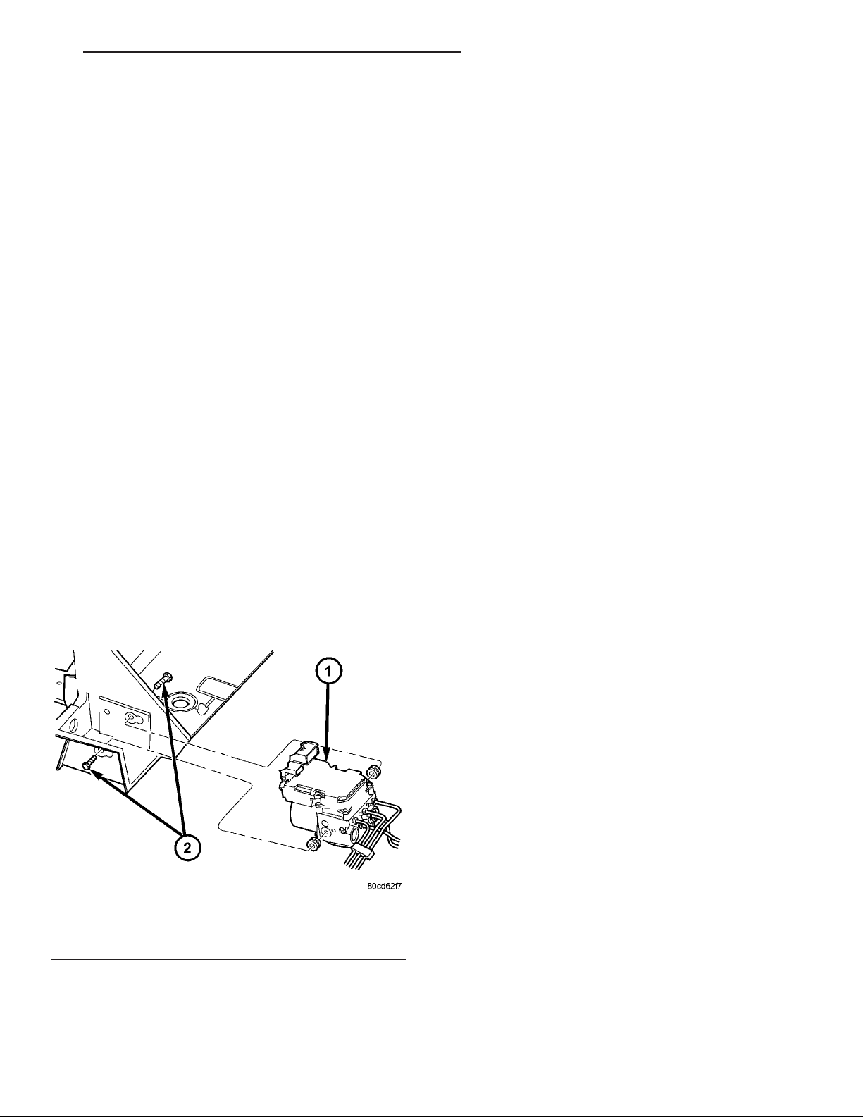
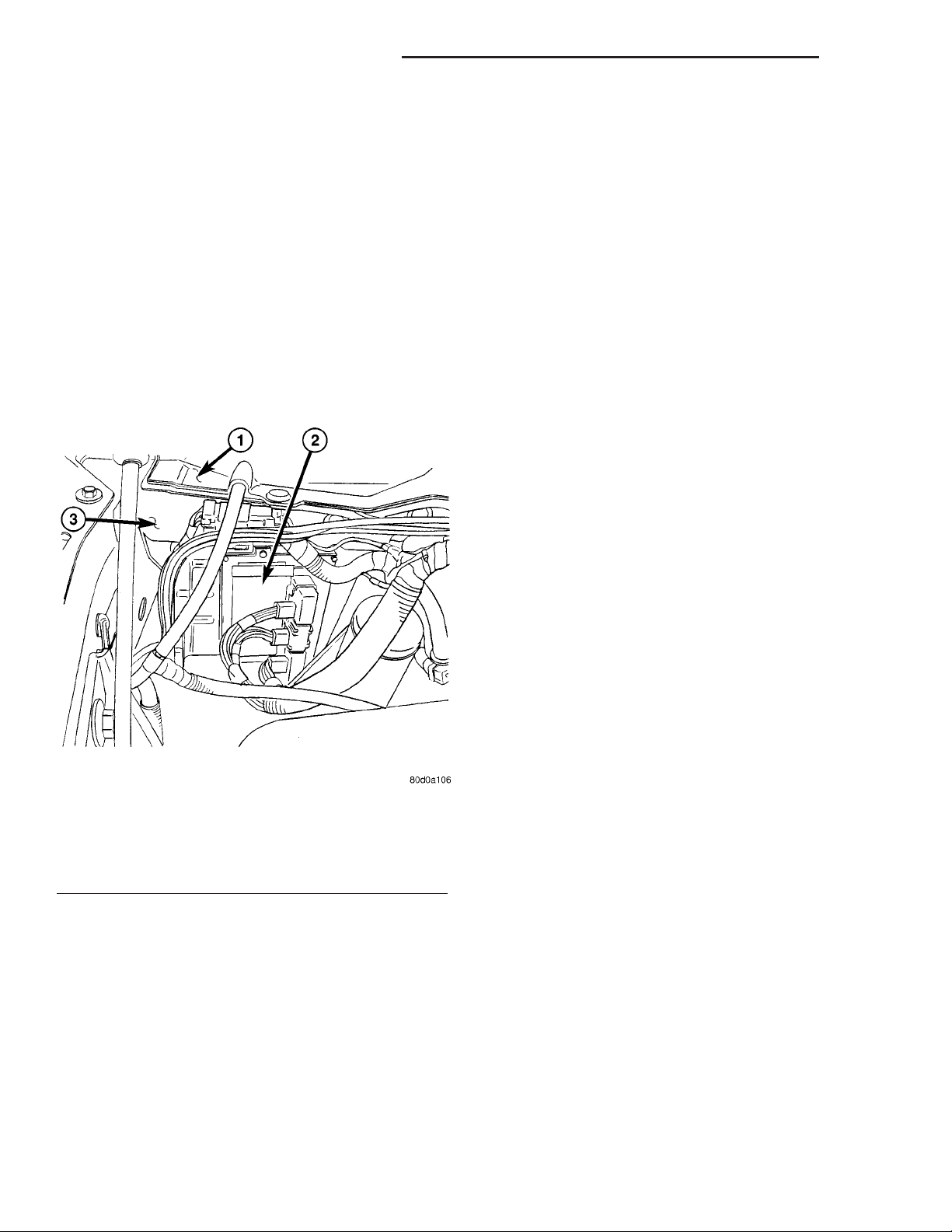
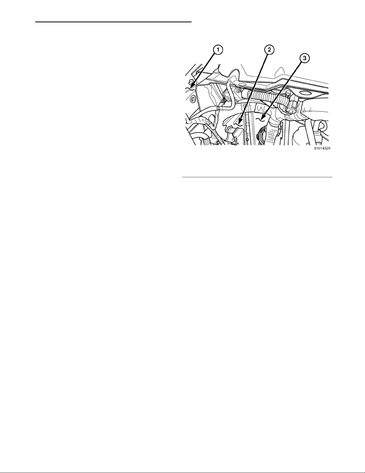
The Controler Antilock Brake (CAB) is mounted to
the Hydraulic Control Unit (HCU) and operates the
ABS system (Fig. 1).
OPERATION
The CAB voltage source is through the ignition
switch in the RUN position. The CAB contains a self
check program that illuminates the ABS warning
light when a system fault is detected. Faults are
stored in a diagnostic program memory and are
accessible with the DRB III scan tool. ABS faults
remain in memory until cleared, or until after the
vehicle is started approximately 50 times. Stored
faults are not erased if the battery is disconnected.
NOTE: If the CAB is being replaced with a new CAB
is must be reprogrammed with the use of a DRB III.
REMOVAL
(1) Remove the negative battery cable from the
battery.
(2) Pull up on the CAB harness connector release
and remove connector.
(3) Remove the CAB mounting bolts.
(4) Remove the pump connector from the CAB.
(5) Remove the CAB from the HCU.
INSTALLATION
NOTE: If the CAB is being replaced with a new CAB
is must be reprogrammed with the use of a DRB III.
(1) Install CAB to the HCU.
(2) Install the pump connector to the CAB.
(3) Install mounting bolts. Tighten to 2 N·m (16 in.
lbs.).
(4) Install the wiring harness connector to the
CAB and push down on the release to secure the connector.
(5) Install negative battery cable to the battery.
Fig. 1 HYDRAULIC CONTROL UNIT
1 - HYDRAULIC CONTROL UNIT
2 - MOUNTING BOLTS
DATA LINK CONNECTOR
DESCRIPTION - DATA LINK CONNECTOR
The Data Link Connector (DLC) is located at the
lower edge of the instrument panel near the steering
column.
OPERATION - DATA LINK CONNECTOR
The 16–way data link connector (diagnostic scan
tool connector) links the Diagnostic Readout Box
(DRB) scan tool or the Mopar Diagnostic System
(MDS) with the Powertrain Control Module (PCM).
Page 4
8E - 4 ELECTRONIC CONTROL MODULES DR
ENGINE CONTROL MODULE
DESCRIPTION - ECM
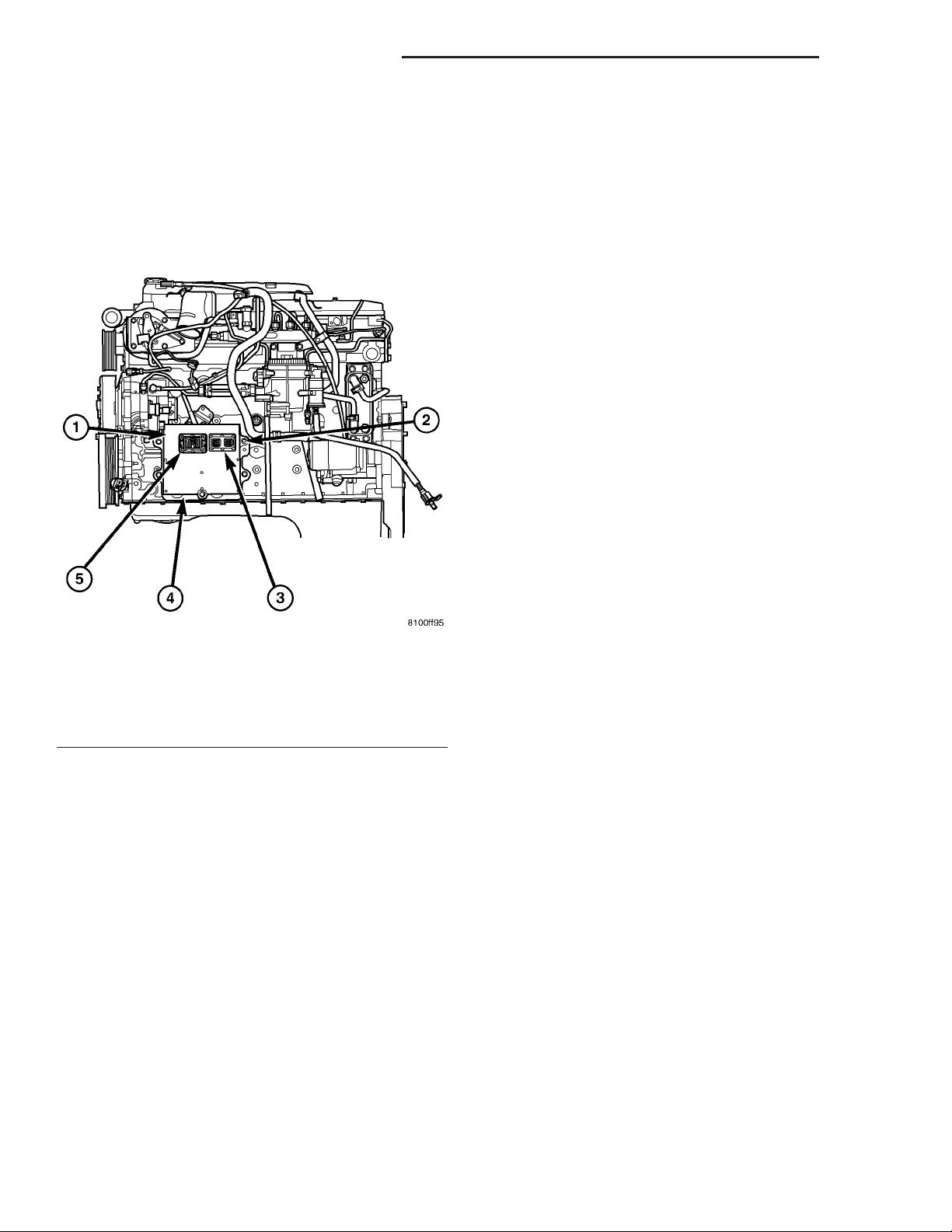
The Engine Control Module (ECM) is bolted to the
left side of the engine below the intake manifold (Fig.
2).
NOTE: ECM Inputs:
• Accelerator Pedal Position Sensor (APPS) Volts
• APPS1 Signal — For off engine APPS
• APPS2 Signal — For off engine APPS
• APPS Idle Validation Switches #1 and #2
• Battery voltage
• Camshaft Position Sensor (CMP)
• CCD bus (+) circuits
• CCD bus (-) circuits
• Crankshaft Position Sensor (CKP)
• Data link connection for DRB scan tool
• Engine Coolant Temperature (ECT) sensor
• Ground circuits
• Fuel Pressure Sensor
• Battery Temperature
• Fan speed
• Inlet Air Temperature Sensor/Pressure Sensor
• Intake Air Temperature Sensor/MAP Sensor
• Oil Pressure SWITCH
• Power ground
• Sensor return
• Signal ground
• Water-In-Fuel (WIF) sensor
Fig. 2 DIESEL ECM
1 - ENGINE CONTROL MODULE (ECM)
2 - ECM MOUNTING BOLT
3 - 50-WAY CONNECTOR
4 - SUPPORT PLATE
5 - 60-WAY CONNECTOR
OPERATION - ECM
The main function of the Engine Control Module
(ECM) is to electrically control the fuel system. The
Powertrain Control Module (PCM) does not control
the fuel system.
The ECM can adapt its programming to meet
changing operating conditions. If the ECM has
been replaced, flashed or re-calibrated, the
ECM must learn the Accelerator Pedal Position
Sensor (APPS) idle voltage. Failure to learn
this voltage may result in unnecessary diagnostic trouble codes. Refer to ECM Removal/Installation for learning procedures.
The ECM receives input signals from various
switches and sensors. Based on these inputs, the
ECM regulates various engine and vehicle operations
through different system components. These components are referred to as ECM Outputs. The sensors
and switches that provide inputs to the ECM are
considered ECM Inputs.
NOTE: ECM Outputs:
After inputs are received by the ECM, certain sensors, switches and components are controlled or regulated by the ECM. These are considered ECM
Outputs. These outputs are for:
• CCD bus (+) circuits
• CCD bus (-) circuits
• CKP and APPS outputs to the PCM
• Data link connection for DRB scan tool
• Five volt sensor supply
• Fuel transfer (lift) pump
• Intake manifold air heater relays #1 and #2 con-
trol circuits
• Malfunction indicator lamp (Check engine lamp)
(databus)
• Oil Pressure Swith/warning lamp (databus)
• Fuel Control Actuator
• Wait-to-start warning lamp (databus)
• Fan Clutch PWM
• Water-In-Fuel (WIF) warning lamp (databus)
REMOVAL
The Engine Control Module (ECM) is bolted to a
support bracket near the fuel filter. The support
bracket mounts to the block with four capscrews and
vibration isolators. A ground wire is fastened to the
bracket. The other end of the wire is fastened to the
engine block.
(1) Record any Diagnostic Trouble Codes (DTC’s)
found in the ECM.
Page 5
DR ELECTRONIC CONTROL MODULES 8E - 5
ENGINE CONTROL MODULE (Continued)
To avoid possible voltage spike damage to either
the Engine Control Module ECM, ignition key must
be off, and negative battery cables must be disconnected before unplugging ECM connectors.
(2) Disconnect both negative battery cables at both
batteries.
(3) Remove the 50–way and 60–way connector
bolts at the ECM. Note: Tthe connector bolt is a
female allen head. As bolt is being removed, very carfully remove connectors from the ECM.
(4) Remove five ECM mounting bolts and remove
ECM form the vehicle (Fig. 3).
(6) Turn key to ON position. Without starting
engine, slowly press throttle pedal to floor and
then slowly release. This step must be done
(one time) to ensure accelerator pedal position
sensor calibration has been learned by ECM. If
not done, possible DTC’s may be set.
(7) Use DRB scan tool to erase any stored compan-
ion DTC’s from ECM.
FRONT CONTROL MODULE
DESCRIPTION
The Front Control Module (FCM) is a micro controller based module located in the left front corner
of the engine compartment. On this model the integrated power module must be positioned aside in
order to access the front control module. The front
control module mates to the power distribution center to form the Integrated Power Module (IPM). The
integrated power module connects directly to the battery and provides the primary means of circuit protection and power distribution for all vehicle
electrical systems. The front control module controls
power to some of these vehicle systems electrical and
electromechanical loads based on inputs received
from hard wired switch inputs and data received on
the PCI bus circuit (J1850).
For information on the Integrated Power Mod-
ule Refer to the Power Distribution Section of
the service manual.
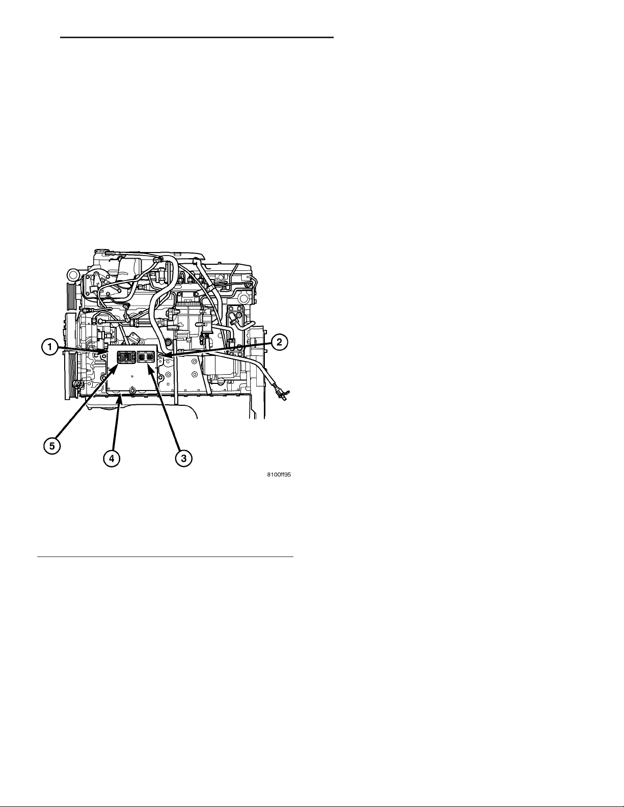
Fig. 3 DIESEL ECM
1 - ENGINE CONTROL MODULE (ECM)
2 - ECM MOUNTING BOLT
3 - 50-WAY CONNECTOR
4 - SUPPORT PLATE
5 - 60-WAY CONNECTOR
INSTALLATION
Do not apply paint to ECM. Poor ground will
result.
(1) Position ECM to ECM support bracket and
install five mounting bolts. Tighten bolts to 24 N·m
(18 ft. lbs.).
(2) Check pin connectors in ECM and the 50–way
and 60–way connectors for corrosion or damage.
Repair as necessary.
(3) Clean pins in the 50–way and 60–way electrical connectors with a quick-dry electrical contact
cleaner.
(4) Very carefully install the 50–way and 60–way
connectors to ECM. Tighten connector allen bolts.
(5) Install both negative battery cables.
OPERATION
As messages are sent over the PCI bus circuit, the
front control module reads these messages and controls power to some of the vehicles electrical systems
by completing the circuit to ground (low side driver)
or completing the circuit to 12 volt power (high side
driver). The following functions are Controlled by
the Front Control Module:
• Headlamp Power with Voltage Regulation
• Windshield Wiper “ON/OFF” Relay Actuation
• Windshield Wiper “HI/LO” Relay Actuation
• Windshield Washer Pump Motor
• Fog Lamp Relay Actuation
• Park Lamp Relay Actuation
• Horn Relay Actuation
The following inputs are Received/Monitored by
the Front Control Module:
• B+ Connection Detection
• Power Ground
• Ambient Temperature Sensing
• Ignition Switch Run
• Washer Fluid Level Switch
• Windshield Wiper Park Switch
• PCI Bus Circuit
Page 6
8E - 6 ELECTRONIC CONTROL MODULES DR
FRONT CONTROL MODULE (Continued)
DIAGNOSIS AND TESTING - FRONT CONTROL
MODULE
The front control module is a printed circuit board
based module with a on-board micro-processor. The
front control module interfaces with other electronic
modules in the vehicle via the Programmable Communications Interface (PCI) data bus (J1850). In
order to obtain conclusive testing the Programmable
Communications Interface (PCI) data bus network
and all of the electronic modules that provide inputs
to, or receive outputs from the front control module
must be checked. All PCI (J1850) communication
faults must be resolved prior to further diagnosing
any front control module related issues.
The front control module was designed to be diagnosed with an appropriate diagnostic scan tool, such
as the DRB IIIt. The most reliable, efficient, and
accurate means to diagnose the front control module
requires the use of a DRB IIIt scan tool and the
proper Body Diagnostic Procedures manual.
Before any testing of the front control module is
attempted, the battery should be fully charged and
all wire harness and ground connections inspected
around the affected areas on the vehicle.
REMOVAL
(1) Disconnect the positive and negative battery
cables from the battery.
(2) Partially remove the integrated power module
from the engine compartment (Refer to 8 - ELECTRICAL/POWER DISTRIBUTION/INTEGRATED
POWER MODULE - REMOVAL).
(3) Remove the front control module retaining
screws.
(4) Using both hands, pull the front control module
straight from the integrated power module assembly
to disconnect the 49-way electrical connector and
remove the front control module from the vehicle.
INSTALLATION
(1) Install the front control module on the integrated power module assembly by pushing the
49-way electrical connector straight in.
(2) Install the front control module retaining
screws. Torque the screws to 7 in. lbs.
(3) Install the integrated power module (Refer to 8
- ELECTRICAL/POWER DISTRIBUTION/INTEGRATED POWER MODULE - INSTALLATION).
(4) Connect the positive and negative battery
cables.
HEATED SEAT MODULE
DESCRIPTION
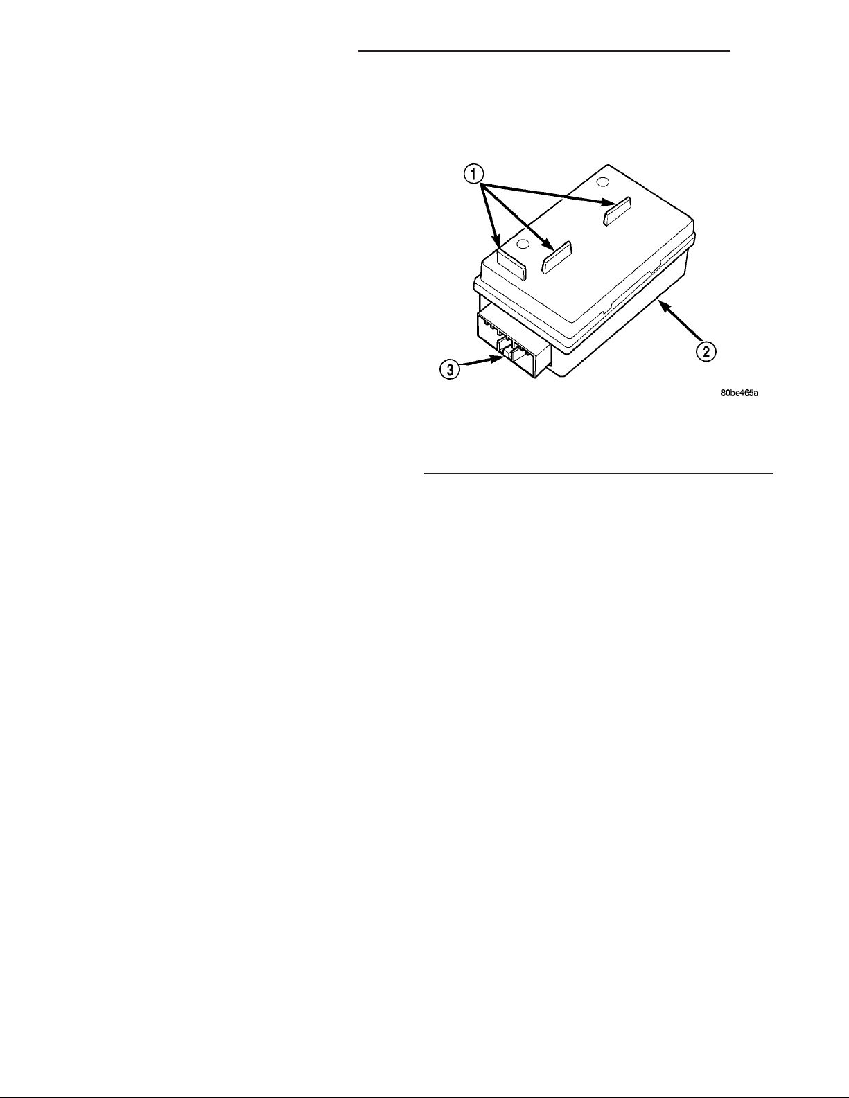
Fig. 4 Heated Seat Module
1 - MOUNTING TABS (NOT USED ON DR)
2 - HEATED SEAT MODULE
3 - ELECTRICAL CONNECTOR RECEPTACLE
The heated seat module is also known as the Seat
Heat Interface Module. The heated seat module (Fig.
4) is located under the drivers front seat cushion,
where it is secured to a mounting bracket. The
heated seat module has a single connector receptacle
that allows the module to be connected to all of the
required inputs and outputs through the seat wire
harness.
The heated seat module is an electronic microprocessor controlled device designed and programmed to
use inputs from the battery, the two heated seat
switches and the two heated seat sensors to operate
and control the heated seat elements in both front
seats and the two heated seat indicator lamp LightEmitting Diodes (LEDs) in each heated seat switch.
The heated seat module is also programmed to perform self-diagnosis of certain heated seat system
functions and provide feedback of that diagnosis
through the heated seat switch indicator lamps.
The heated seat module cannot be repaired. If the
heated seat module is damaged or faulty, the entire
module must be replaced.
OPERATION
The heated seat module operates on fused battery
current received from the integrated power module.
Inputs to the module include a resistor multiplexed
heated seat switch request circuit for each of the two
heated seat switches and the heated seat sensor
inputs from the seat cushions of each front seat. In
response to those inputs the heated seat module controls battery current feeds to the heated seat ele-
Page 7

DR ELECTRONIC CONTROL MODULES 8E - 7
HEATED SEAT MODULE (Continued)
ments and sensors, and controls the ground for the
heated seat switch indicator lamps.
When a heated seat switch (Driver or Passenger) is
depressed a signal is received by the heated seat
module, the module energizes the proper indicator
LED (Low or High) in the switch by grounding the
indicator lamp circuit to indicate that the heated seat
system is operating. At the same time, the heated
seat module energizes the selected heated seat sensor
circuit and the sensor provides the module with an
input indicating the surface temperature of the
selected seat cushion.
The Low heat set point is about 36° C (96.8° F),
and the High heat set point is about 42° C (107.6° F).
If the seat cushion surface temperature input is
below the temperature set point for the selected temperature setting, the heated seat module energizes
an N-channel Field Effect Transistor (N-FET) within
the module which energizes the heated seat elements
in the selected seat cushion and back. When the sensor input to the module indicates the correct temperature set point has been achieved, the module
de-energizes the N-FET which de-energizes the
heated seat elements. The heated seat module will
continue to cycle the N-FET as needed to maintain
the selected temperature set point.
If the heated seat module detects a heated seat
sensor value input that is out of range or a shorted
or open heated seat element circuit, it will notify the
vehicle operator or the repair technician of this condition by flashing the High and/or Low indicator
lamps in the affected heated seat switch. Refer to
Diagnosis and Testing Heated Seat System in
Heated Systems for flashing LED diagnosis and testing procedures. Refer to Diagnosis and Testing
Heated Seat Module in this section for heated seat
module diagnosis and testing procedures.
DIAGNOSIS AND TESTING - HEATED SEAT
MODULE
If a heated seat fails to heat and one or both of the
indicator lamps on a heated seat switch flash, refer
to Diagnosis and Testing Heated Seat System in
Heated Seats for the location of flashing LED heated
seat system diagnosis and testing procedures. If a
heated seat heats but one or both indicator lamps on
the heated seat switch fail to operate, test the heated
seat switch. Refer to Diagnosis and Testing
Heated Seat Switch in Heated Seats for heated
seat switch diagnosis and testing procedures. If the
heated seat switch checks OK, proceed as follows.
(1) Check the heated seat element (Refer to 8 ELECTRICAL/HEATED SEATS/HEATED SEAT
ELEMENT - DIAGNOSIS AND TESTING).
(2) Check the heated seat sensor (Refer to 8 ELECTRICAL/HEATED SEATS/HEATED SEAT
SENSOR - DIAGNOSIS AND TESTING).
(3) Check the heated seat switch (Refer to 8 ELECTRICAL/HEATED SEATS/DRIVER HEATED
SEAT SWITCH - DIAGNOSIS AND TESTING).
NOTE: Refer to Wiring for the location of complete
heated seat system wiring diagrams and connector
pin-out information.
(4) Using a voltmeter, backprobe the appropriate
heated seat module connector, do not disconnect.
Check for voltage at the appropriate pin cavities. 12v
should be present. If OK go to Step 5, if Not, Repair
the open or shorted voltage supply circuit as
required.
(5) Using a ohmmeter, backprobe the appropriate
heated seat module connector, do not disconnect.
Check for proper continuity to ground on the ground
pin cavities. Continuity should be present. If OK
replace the heated seat module with a known good
unit and retest system, if Not OK, Repair the open or
shorted ground circuit as required.
REMOVAL
(1) Position the driver seat to the full rearward
and inclined position.
(2) Working under the driver front seat, remove
the two heated seat module retaining screws. Due to
the fact that the retaining screws are installed with
the seat cushion pan removed, a small right angle
screwdriver will be required to access and remove the
screws.
(3) Disconnect the seat wire harness connector
from the connector receptacle on the back of the
heated seat module. Depress the connector retaining
tab and pull straight apart.
(4) Remove the heated seat module from under the
front seat.
INSTALLATION
(1) Position the heated seat module under the
front seat.
(2) Connect the seat wire harness connector on the
connector receptacle on the back of the heated seat
module.
(3) Working under the driver front seat, install the
heated seat module retaining screws.
(4) Re-position the driver seat.
Page 8
8E - 8 ELECTRONIC CONTROL MODULES DR
POWERTRAIN CONTROL
MODULE
DESCRIPTION
DESCRIPTION - PCM
The Powertrain Control Module (PCM) is located
in the right-rear section of the engine compartment
under the cowl (Fig. 5).
Two different PCM’s are used (JTEC and
NGC). These can be easily identified. JTEC’s
use three 32–way connectors, NGC’s use four
38–way connectors
During Closed Loop modes, the PCM will monitor
the oxygen (O2S) sensors input. This input indicates
to the PCM whether or not the calculated injector
pulse width results in the ideal air-fuel ratio. This
ratio is 14.7 parts air-to-1 part fuel. By monitoring
the exhaust oxygen content through the O2S sensor,
the PCM can fine tune the injector pulse width. This
is done to achieve optimum fuel economy combined
with low emission engine performance.
The fuel injection system has the following modes
of operation:
• Ignition switch ON
• Engine start-up (crank)
• Engine warm-up
• Idle
• Cruise
• Acceleration
• Deceleration
• Wide open throttle (WOT)
• Ignition switch OFF
The ignition switch On, engine start-up (crank),
engine warm-up, acceleration, deceleration and wide
open throttle modes are Open Loop modes. The idle
and cruise modes, (with the engine at operating temperature) are Closed Loop modes.
Fig. 5 POWERTRAIN CONTROL MODULE (PCM)
LOCATION
1 - COWL GRILL
2 - PCM
3 - COWL (RIGHT-REAR)
DESCRIPTION - MODES OF OPERATION
As input signals to the Powertrain Control Module
(PCM) change, the PCM adjusts its response to the
output devices. For example, the PCM must calculate
different injector pulse width and ignition timing for
idle than it does for wide open throttle (WOT).
The PCM will operate in two different modes:
Open Loop and Closed Loop.
During Open Loop modes, the PCM receives input
signals and responds only according to preset PCM
programming. Input from the oxygen (O2S) sensors
is not monitored during Open Loop modes.
IGNITION SWITCH (KEY-ON) MODE
This is an Open Loop mode. When the fuel system
is activated by the ignition switch, the following
actions occur:
• The PCM pre-positions the idle air control (IAC)
motor.
• The PCM determines atmospheric air pressure
from the MAP sensor input to determine basic fuel
strategy.
• The PCM monitors the engine coolant temperature sensor input. The PCM modifies fuel strategy
based on this input.
• Intake manifold air temperature sensor input is
monitored.
• Throttle position sensor (TPS) is monitored.
• The auto shutdown (ASD) relay is energized by
the PCM for approximately three seconds.
• The fuel pump is energized through the fuel
pump relay by the PCM. The fuel pump will operate
for approximately three seconds unless the engine is
operating or the starter motor is engaged.
• The O2S sensor heater element is energized via
the ASD or O2S heater relay. The O2S sensor input
is not used by the PCM to calibrate air-fuel ratio during this mode of operation.
ENGINE START-UP MODE
This is an Open Loop mode. The following actions
occur when the starter motor is engaged.
The PCM receives inputs from:
Page 9

DR ELECTRONIC CONTROL MODULES 8E - 9
POWERTRAIN CONTROL MODULE (Continued)
• Battery voltage
• Engine coolant temperature sensor
• Crankshaft position sensor
• Intake manifold air temperature sensor
• Manifold absolute pressure (MAP) sensor
• Throttle position sensor (TPS)
• Camshaft position sensor signal
The PCM monitors the crankshaft position sensor.
If the PCM does not receive a crankshaft position
sensor signal within 3 seconds of cranking the
engine, it will shut down the fuel injection system.
The fuel pump is activated by the PCM through
the fuel pump relay.
Voltage is applied to the fuel injectors with the
ASD relay via the PCM. The PCM will then control
the injection sequence and injector pulse width by
turning the ground circuit to each individual injector
on and off.
The PCM determines the proper ignition timing
according to input received from the crankshaft position sensor.
ENGINE WARM-UP MODE
This is an Open Loop mode. During engine warmup, the PCM receives inputs from:
• Battery voltage
• Crankshaft position sensor
• Engine coolant temperature sensor
• Intake manifold air temperature sensor
• Manifold absolute pressure (MAP) sensor
• Throttle position sensor (TPS)
• Camshaft position sensor signal
• Park/neutral switch (gear indicator signal—auto.
trans. only)
• Air conditioning select signal (if equipped)
• Air conditioning request signal (if equipped)
Based on these inputs the following occurs:
• Voltage is applied to the fuel injectors with the
ASD relay via the PCM. The PCM will then control
the injection sequence and injector pulse width by
turning the ground circuit to each individual injector
on and off.
• The PCM adjusts engine idle speed through the
idle air control (IAC) motor and adjusts ignition timing.
• The PCM operates the A/C compressor clutch
through the A/C compressor clutch relay. This is done
if A/C has been selected by the vehicle operator and
specified pressures are met at the high and low–pressure A/C switches. Refer to Heating and Air Conditioning for additional information.
• When engine has reached operating temperature, the PCM will begin monitoring O2S sensor
input. The system will then leave the warm-up mode
and go into closed loop operation.
IDLE MODE
When the engine is at operating temperature, this
is a Closed Loop mode. At idle speed, the PCM
receives inputs from:
• Air conditioning select signal (if equipped)
• Air conditioning request signal (if equipped)
• Battery voltage
• Crankshaft position sensor
• Engine coolant temperature sensor
• Intake manifold air temperature sensor
• Manifold absolute pressure (MAP) sensor
• Throttle position sensor (TPS)
• Camshaft position sensor signal
• Battery voltage
• Park/neutral switch (gear indicator signal—auto.
trans. only)
• Oxygen sensors
Based on these inputs, the following occurs:
• Voltage is applied to the fuel injectors with the
ASD relay via the PCM. The PCM will then control
injection sequence and injector pulse width by turning the ground circuit to each individual injector on
and off.
• The PCM monitors the O2S sensor input and
adjusts air-fuel ratio by varying injector pulse width.
It also adjusts engine idle speed through the idle air
control (IAC) motor.
• The PCM adjusts ignition timing by increasing
and decreasing spark advance.
• The PCM operates the A/C compressor clutch
through the A/C compressor clutch relay. This is done
if A/C has been selected by the vehicle operator and
specified pressures are met at the high and low–pressure A/C switches. Refer to Heating and Air Conditioning for additional information.
CRUISE MODE
When the engine is at operating temperature, this
is a Closed Loop mode. At cruising speed, the PCM
receives inputs from:
• Air conditioning select signal (if equipped)
• Air conditioning request signal (if equipped)
• Battery voltage
• Engine coolant temperature sensor
• Crankshaft position sensor
• Intake manifold air temperature sensor
• Manifold absolute pressure (MAP) sensor
• Throttle position sensor (TPS)
• Camshaft position sensor signal
• Park/neutral switch (gear indicator signal—auto.
trans. only)
• Oxygen (O2S) sensors
Based on these inputs, the following occurs:
• Voltage is applied to the fuel injectors with the
ASD relay via the PCM. The PCM will then adjust
Page 10

8E - 10 ELECTRONIC CONTROL MODULES DR
POWERTRAIN CONTROL MODULE (Continued)
the injector pulse width by turning the ground circuit
to each individual injector on and off.
• The PCM monitors the O2S sensor input and
adjusts air-fuel ratio. It also adjusts engine idle
speed through the idle air control (IAC) motor.
• The PCM adjusts ignition timing by turning the
ground path to the coil(s) on and off.
• The PCM operates the A/C compressor clutch
through the clutch relay. This happens if A/C has
been selected by the vehicle operator and requested
by the A/C thermostat.
ACCELERATION MODE
This is an Open Loop mode. The PCM recognizes
an abrupt increase in throttle position or MAP pressure as a demand for increased engine output and
vehicle acceleration. The PCM increases injector
pulse width in response to increased throttle opening.
DECELERATION MODE
When the engine is at operating temperature, this
is an Open Loop mode. During hard deceleration, the
PCM receives the following inputs.
• Air conditioning select signal (if equipped)
• Air conditioning request signal (if equipped)
• Battery voltage
• Engine coolant temperature sensor
• Crankshaft position sensor
• Intake manifold air temperature sensor
• Manifold absolute pressure (MAP) sensor
• Throttle position sensor (TPS)
• Camshaft position sensor signal
• Park/neutral switch (gear indicator signal—auto.
trans. only)
• Vehicle speed
If the vehicle is under hard deceleration with the
proper rpm and closed throttle conditions, the PCM
will ignore the oxygen sensor input signal. The PCM
will enter a fuel cut-off strategy in which it will not
supply a ground to the injectors. If a hard deceleration does not exist, the PCM will determine the
proper injector pulse width and continue injection.
Based on the above inputs, the PCM will adjust
engine idle speed through the idle air control (IAC)
motor.
The PCM adjusts ignition timing by turning the
ground path to the coil on and off.
WIDE OPEN THROTTLE MODE
This is an Open Loop mode. During wide open
throttle operation, the PCM receives the following
inputs.
• Battery voltage
• Crankshaft position sensor
• Engine coolant temperature sensor
• Intake manifold air temperature sensor
• Manifold absolute pressure (MAP) sensor
• Throttle position sensor (TPS)
• Camshaft position sensor signal
During wide open throttle conditions, the following
occurs:
• Voltage is applied to the fuel injectors with the
ASD relay via the PCM. The PCM will then control
the injection sequence and injector pulse width by
turning the ground circuit to each individual injector
on and off. The PCM ignores the oxygen sensor input
signal and provides a predetermined amount of additional fuel. This is done by adjusting injector pulse
width.
• The PCM adjusts ignition timing by turning the
ground path to the coil(s) on and off.
IGNITION SWITCH OFF MODE
When ignition switch is turned to OFF position,
the PCM stops operating the injectors, ignition coil,
ASD relay and fuel pump relay.
DESCRIPTION - 5 VOLT SUPPLIES
Two different Powertrain Control Module (PCM)
five volt supply circuits are used; primary and secondary.
DESCRIPTION - IGNITION CIRCUIT SENSE
This circuit ties the ignition switch to the Powertrain Control Module (PCM).
DESCRIPTION - POWER GROUNDS
The Powertrain Control Module (PCM) has 2 main
grounds. Both of these grounds are referred to as
power grounds. All of the high-current, noisy, electrical devices are connected to these grounds as well as
all of the sensor returns. The sensor return comes
into the sensor return circuit, passes through noise
suppression, and is then connected to the power
ground.
The power ground is used to control ground circuits for the following PCM loads:
• Generator field winding
• Fuel injectors
• Ignition coil(s)
• Certain relays/solenoids
• Certain sensors
DESCRIPTION - SENSOR RETURN
The Sensor Return circuits are internal to the Powertrain Control Module (PCM).
Sensor Return provides a low–noise ground reference for all engine control system sensors. Refer to
Power Grounds for more information.
Page 11

DR ELECTRONIC CONTROL MODULES 8E - 11
POWERTRAIN CONTROL MODULE (Continued)
OPERATION
OPERATION - PCM
The PCM operates the fuel system. The PCM is a
pre-programmed, triple microprocessor digital computer. It regulates ignition timing, air-fuel ratio,
emission control devices, charging system, certain
transmission features, speed control, air conditioning
compressor clutch engagement and idle speed. The
PCM can adapt its programming to meet changing
operating conditions.
The PCM receives input signals from various
switches and sensors. Based on these inputs, the
PCM regulates various engine and vehicle operations
through different system components. These components are referred to as Powertrain Control Module
(PCM) Outputs. The sensors and switches that provide inputs to the PCM are considered Powertrain
Control Module (PCM) Inputs.
The PCM adjusts ignition timing based upon
inputs it receives from sensors that react to: engine
rpm, manifold absolute pressure, engine coolant temperature, throttle position, transmission gear selection (automatic transmission), vehicle speed, power
steering pump pressure, and the brake switch.
The PCM adjusts idle speed based on inputs it
receives from sensors that react to: throttle position,
vehicle speed, transmission gear selection, engine
coolant temperature and from inputs it receives from
the air conditioning clutch switch and brake switch.
Based on inputs that it receives, the PCM adjusts
ignition coil dwell. The PCM also adjusts the generator charge rate through control of the generator
field and provides speed control operation.
NOTE: PCM Inputs:
• ABS module (if equipped)
• A/C request (if equipped with factory A/C)
• A/C select (if equipped with factory A/C)
• A/C pressure transducer
• Auto shutdown (ASD) sense
• Battery temperature sensor
• Battery voltage
• Brake switch
• J1850 bus (+) circuits
• J1850 bus (-) circuits
• Camshaft position sensor signal
• Crankshaft position sensor
• Data link connection for DRB scan tool
• EATX module (if equipped)
• Engine coolant temperature sensor
• Fuel level (through J1850 circuitry)
• Generator (battery voltage) output
• Ignition circuit sense (ignition switch in on/off/
crank/run position)
• Intake manifold air temperature sensor
• Knock sensors (2 on 3.7L engine)
• Leak detection pump (switch) sense (if equipped)
• Manifold absolute pressure (MAP) sensor
• Oil pressure
• Oxygen sensors
• Park/neutral switch (auto. trans. only)
• Power ground
• Power steering pressure switch (if equipped)
• Sensor return
• Signal ground
• Speed control multiplexed single wire input
• Throttle position sensor
• Transfer case switch (4WD range position)
• Vehicle speed signal
NOTE: PCM Outputs:
• A/C clutch relay
• Auto shutdown (ASD) relay
• J1850 bus (+/-) circuits for: speedometer, voltme-
ter, fuel gauge, oil pressure gauge/lamp, engine temp.
gauge and speed control warn. lamp
• Data link connection for DRB scan tool
• EGR valve control solenoid (if equipped)
• EVAP canister purge solenoid
• Five volt sensor supply (primary)
• Five volt sensor supply (secondary)
• Fuel injectors
• Fuel pump relay
• Generator field driver (-)
• Generator field driver (+)
• Idle air control (IAC) motor
• Ignition coil(s)
• Leak detection pump (if equipped)
• Malfunction indicator lamp (Check engine lamp).
Driven through J1850 circuits.
• Oxygen sensor heater relays
• Oxygen sensors (pulse width modulated)
• Radiator cooling fan relay (pulse width modu-
lated)
• Speed control vacuum solenoid
• Speed control vent solenoid
• Tachometer (if equipped). Driven through J1850
circuits.
• Transmission convertor clutch circuit. Driven
through J1850 circuits.
OPERATION - 5 VOLT SUPPLIES
Primary 5–volt supply:
• supplies the required 5 volt power source to the
Crankshaft Position (CKP) sensor.
• supplies the required 5 volt power source to the
Camshaft Position (CMP) sensor.
• supplies a reference voltage for the Manifold
Absolute Pressure (MAP) sensor.
Page 12
8E - 12 ELECTRONIC CONTROL MODULES DR
POWERTRAIN CONTROL MODULE (Continued)
• supplies a reference voltage for the Throttle
Position Sensor (TPS) sensor.
Secondary 5–volt supply:
• supplies the required 5 volt power source to the
oil pressure sensor.
• supplies the required 5 volt power source for the
Vehicle Speed Sensor (VSS) (if equipped).
• supplies the 5 volt power source to the transmission pressure sensor (certain automatic transmissions).
OPERATION - IGNITION CIRCUIT SENSE
The ignition circuit sense input tells the PCM the
ignition switch has energized the ignition circuit.
Battery voltage is also supplied to the PCM
through the ignition switch when the ignition is in
the RUN or START position. This is referred to as
the 9ignition sense9 circuit and is used to 9wake up9
the PCM. Voltage on the ignition input can be as low
as 6 volts and the PCM will still function. Voltage is
supplied to this circuit to power the PCM’s 8-volt regulator and to allow the PCM to perform fuel, ignition
and emissions control functions.
REMOVAL
USE THE DRB SCAN TOOL TO REPROGRAM
THE NEW POWERTRAIN CONTROL MODULE
(PCM) WITH THE VEHICLES ORIGINAL IDENTIFICATION NUMBER (VIN) AND THE VEHICLES ORIGINAL MILEAGE. IF THIS STEP IS
NOT DONE, A DIAGNOSTIC TROUBLE CODE
(DTC) MAY BE SET.
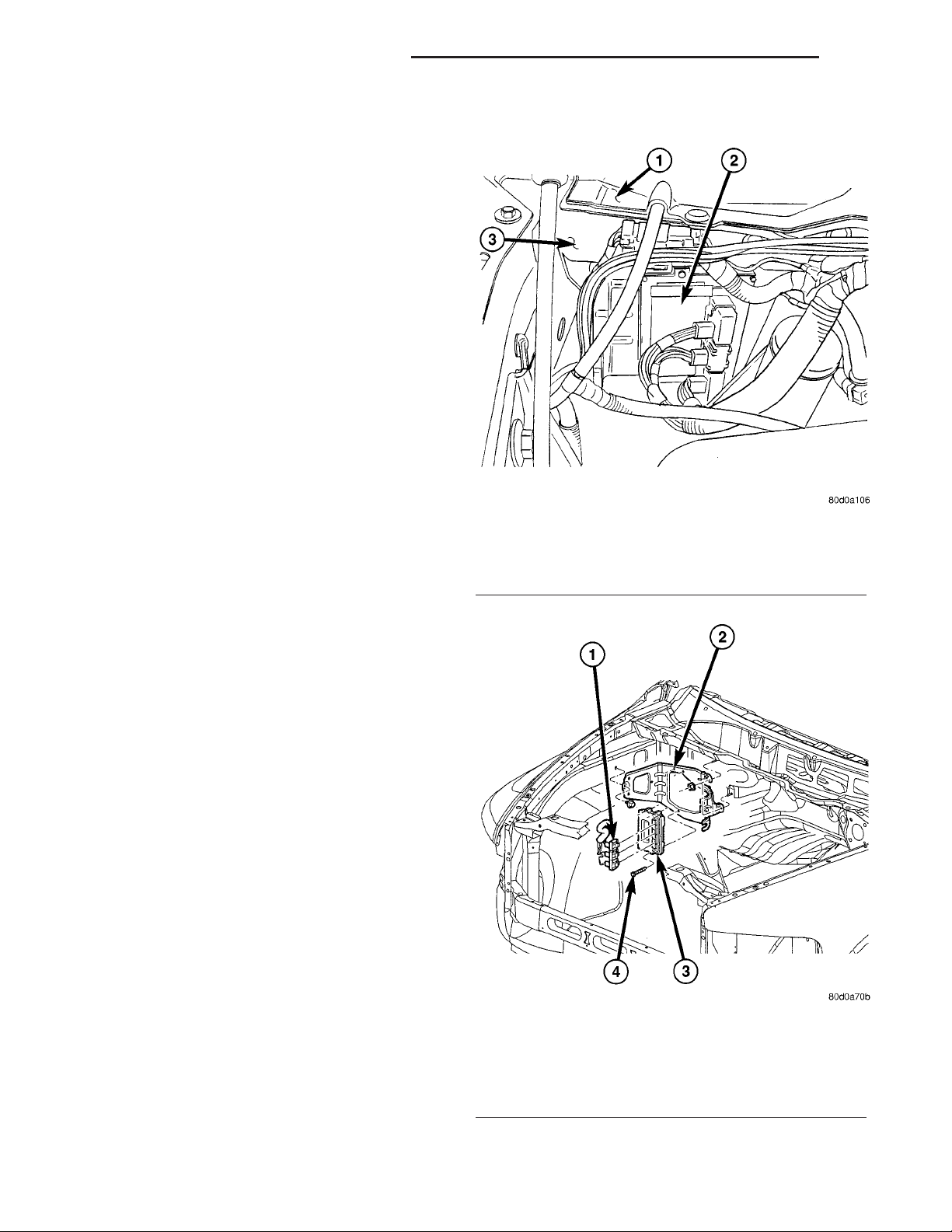
The PCM is located in the engine compartment
attached to the dash panel (Fig. 6).
To avoid possible voltage spike damage to the
PCM, ignition key must be off, and negative battery
cable must be disconnected before unplugging PCM
connectors.
(1) Disconnect negative battery cable at battery.
(2) Remove cover over electrical connectors. Cover
snaps onto PCM.
(3) Carefully unplug the three 32–way connectors
(four 38–way connectors if equipped with NGC) from
PCM (Fig. 7).
(4) Remove three PCM mounting bolts (Fig. 7) and
remove PCM from vehicle.
1 - COWL GRILL
2 - PCM
3 - COWL (RIGHT-REAR)
Fig. 6 PCM LOCATION
INSTALLATION
USE THE DRB SCAN TOOL TO REPROGRAM
THE NEW POWERTRAIN CONTROL MODULE
(PCM) WITH THE VEHICLES ORIGINAL IDENTIFICATION NUMBER (VIN) AND THE VEHICLES ORIGINAL MILEAGE. IF THIS STEP IS
NOT DONE, A DIAGNOSTIC TROUBLE CODE
(DTC) MAY BE SET.
(1) Install PCM and 3 mounting bolts to vehicle.
Fig. 7 PCM REMOVAL / INSTALLATION
1 - THREE 32-WAY CONNECTORS WITH JTEC (FOUR 38-WAY
CONNECTORS WITH NGC)
2 - PCM MOUNTING BRACKET
3 - PCM
4 - PCM MOUNTING SCREWS (3)
Page 13

DR ELECTRONIC CONTROL MODULES 8E - 13
POWERTRAIN CONTROL MODULE (Continued)
(2) Tighten bolts. Refer to torque specifications.
(3) Check pin connectors in the PCM and the three
32–way connectors (four 38–way connectors if
equipped with NGC) for corrosion or damage. Also,
the pin heights in connectors should all be same.
Repair as necessary before installing connectors.
(4) Install three 32–way connectors (four 38–way
connectors if equipped with NGC).
(5) Install cover over electrical connectors. Cover
snaps onto PCM.
(6) Install negative battery cable.
(7) Use the DRB scan tool to reprogram new PCM
with vehicles original Vehicle Identification Number
(VIN) and original vehicle mileage.
SENTRY KEY IMMOBILIZER
MODULE
DESCRIPTION
The Sentry Key Immobilizer Module (SKIM) contains a Radio Frequency (RF) transceiver and a central processing unit, which includes the Sentry Key
Immobilizer System (SKIS) program logic. The SKIS
programming enables the SKIM to program and
retain in memory the codes of at least two, but no
more than eight electronically coded Sentry Key
transponders. The SKIS programming also enables
the SKIM to communicate over the Programmable
Communication Interface (PCI) bus network with the
Powertrain Control Module (PCM), and/or the
DRBIIIt scan tool.
OPERATION
The SKIM transmits and receives RF signals
through a tuned antenna enclosed within a molded
plastic ring that is integral to the SKIM housing.
When the SKIM is properly installed on the steering
column, the antenna ring is oriented around the ignition lock cylinder housing. This antenna ring must be
located within eight millimeters (0.31 inches) of the
Sentry Key in order to ensure proper RF communication between the SKIM and the Sentry Key transponder.
For added system security, each SKIM is programmed with a unique “Secret Key” code and a
security code. The SKIM keeps the “Secret Key” code
in memory. The SKIM also sends the “Secret Key”
code to each of the programmed Sentry Key transponders. The security code is used by the assembly
plant to access the SKIS for initialization, or by the
dealer technician to access the system for service.
The SKIM also stores in its memory the Vehicle
Identification Number (VIN), which it learns through
a PCI bus message from the PCM during initialization.
The SKIM and the PCM both use software that
includes a rolling code algorithm strategy, which
helps to reduce the possibility of unauthorized SKIS
disarming. The rolling code algorithm ensures security by preventing an override of the SKIS through
the unauthorized substitution of the SKIM or the
PCM. However, the use of this strategy also means
that replacement of either the SKIM or the PCM
units will require a system initialization procedure to
restore system operation.
When the ignition switch is turned to the ON or
START positions, the SKIM transmits an RF signal
to excite the Sentry Key transponder. The SKIM then
listens for a return RF signal from the transponder
of the Sentry Key that is inserted in the ignition lock
cylinder. If the SKIM receives an RF signal with
valid “Secret Key” and transponder identification
codes, the SKIM sends a “valid key” message to the
PCM over the PCI bus. If the SKIM receives an
invalid RF signal or no response, it sends “invalid
key” messages to the PCM. The PCM will enable or
disable engine operation based upon the status of the
SKIM messages.
The SKIM also sends messages to the Instrument
Cluster which controls the VTSS indicator LED. The
SKIM sends messages to the Instrument Cluster to
turn the LED on for about three seconds when the
ignition switch is turned to the ON position as a bulb
test. After completion of the bulb test, the SKIM
sends bus messages to keep the LED off for a duration of about one second. Then the SKIM sends messages to turn the LED on or off based upon the
results of the SKIS self-tests. If the VTSS indicator
LED comes on and stays on after the bulb test, it
indicates that the SKIM has detected a system malfunction and/or that the SKIS has become inoperative.
If the SKIM detects an invalid key when the ignition switch is turned to the ON position, it sends
messages to flash the VTSS indicator LED. The
SKIM can also send messages to flash the LED as an
indication to the customer that the SKIS has been
placed in it’s “Customer Learn” programming mode.
See Sentry Key Immobilizer System Transponder
Programming in this section for more information on
the “Customer Learn” programming mode.
For diagnosis or initialization of the SKIM and the
PCM, a DRBIIIt scan tool and the proper Powertrain
Diagnostic Procedures manual are required. The
SKIM cannot be repaired and, if faulty or damaged,
the unit must be replaced.
Page 14

8E - 14 ELECTRONIC CONTROL MODULES DR
SENTRY KEY IMMOBILIZER MODULE (Continued)
STANDARD PROCEDURE - PCM/SKIM
PROGRAMMING
NOTE: There are two procedures for transfering the
secret key to the SKIM:
• When ONLY the SKIM module is replaced, the
secret key is transfered from the PCM to the SKIM.
The ORGINAL KEYS may then be programmed to
the SKIM.
• When ONLY the PCM is replaced, then the
secret key is transfered from the SKIM to the PCM.
The ORGINAL KEYS may be used.
• When BOTH the SKIM and the PCM are
replaced the secret key is transferred from the
SKIM to the PCM, and NEW KEYS must be programmed.
NOTE: Before replacing the Powertrain Control
Module (PCM) for a failed driver, control circuit, or
ground circuit, be sure to check the related component/circuit integrity for failures not detected due to
a double fault in the circuit. Most PCM driver/control circuit failures are caused by internal component failures (i.e. relay and solenoids) and shorted
circuits (i.e. pull-ups, drivers and switched circuits).
These failures are difficult to detect when a double
fault has occurred and only one Diagnostic Trouble
Code (DTC) has set.
When a PCM (SBEC) and the Sentry Key Immobilizer Module (SKIM) are replaced at the same time
perform the following steps in order:
(1) Program the new PCM (SBEC).
(2) Program the new SKIM.
(3) Replace all ignition keys and program them to
the new SKIM.
PROGRAMMING THE PCM (SBEC)
The Sentry Key Immobilizer System (SKIS) Secret
Key is an ID code that is unique to each SKIM. This
code is programmed and stored in the SKIM, PCM
and transponder chip (ignition keys). When replacing
the PCM it is necessary to program the secret key
into the new PCM using the DRBIIIt scan tool. Perform the following steps to program the secret key
into the PCM.
(1) Turn the ignition switch on (transmission in
park/neutral).
(2) Use the DRBIIIt scan tool and select THEFT
ALARM, SKIM then MISCELLANEOUS.
(3) Select PCM REPLACED (GAS ENGINE).
(4) Enter secured access mode by entering the
vehicle four-digit PIN.
(5) Select ENTER to update PCM VIN.
NOTE: If three attempts are made to enter secure
access mode using an incorrect PIN, secured
access mode will be locked out for one hour. To
exit this lockout mode, turn the ignition to the RUN
position for one hour then enter the correct PIN.
(Ensure all accessories are turned OFF. Also monitor the battery state and connect a battery charger
if necessary).
(6) Press ENTER to transfer the secret key (the
SKIM will send the secret key to the PCM).
(7) Press Page Back to get to the Select System
menu and select ENGINE, MISCELLANEOUS, and
SRI MEMORY CHECK.
(8) The DRBIIIt scan tool will ask, Is odometer
reading between XX and XX? Select the YES or NO
button on the DRB IIIt scan tool. If NO is selected,
the DRBIIIt scan tool will read, Enter odometer
Reading<From I.P. odometer>. Enter the odometer
reading from the instrument cluster and press
ENTER.
PROGRAMMING THE SKIM
(1) Turn the ignition switch on (transmission in
park/neutral).
(2) Use the DRBIIIt scan tool and select THEFT
ALARM, SKIM then MISCELLANEOUS.
(3) Select SKIM REPLACED (GAS ENGINE).
(4) Program the vehicle four-digit PIN into SKIM.
(5) Select COUNTRY CODE and enter the correct
country.
NOTE: Be sure to enter the correct country code. If
the incorrect country code is programmed into the
SKIM, the SKIM must be replaced.
(6) Select YES to update the VIN (the SKIM will
learn the VIN from the PCM).
(7) Press ENTER to transfer the secret key (the
PCM will send the secret key information to the
SKIM).
(8) Program ignition keys to the SKIM.
NOTE: If the PCM and the SKIM are replaced at the
same time, all vehicle keys will need to be replaced
and programmed to the new SKIM.
PROGRAMMING IGNITION KEYS TO THE SKIM
(1) Turn the ignition switch on (transmission in
park/neutral).
(2) Use the DRBIIIt scan tool and select THEFT
ALARM, SKIM then MISCELLANEOUS.
(3) Select PROGRAM IGNITION KEY’S.
(4) Enter secured access mode by entering the
vehicle four-digit PIN.
Page 15
DR ELECTRONIC CONTROL MODULES 8E - 15
SENTRY KEY IMMOBILIZER MODULE (Continued)
NOTE: A maximum of eight keys can be learned to
each SKIM. Once a key is learned to a SKIM, it (the
key) cannot be transferred to another vehicle.
(5) If ignition key programming is unsuccessful,
the DRBIIIt scan tool will display one of the following messages:
(a) Programming Not Attempted - The DRBIIIt
scan tool attempts to read the programmed key
status and there are no keys programmed into
SKIM memory.
(b) Programming Key Failed (Possible Used Key
From Wrong Vehicle) - SKIM is unable to program
key due to one of the following:
• Faulty ignition key transponder.
• Ignition key is programmed to another vehicle.
(c) 8 Keys Already Learned, Programming Not
Done - SKIM transponder ID memory is full.
(6) Obtain ignition keys to be programmed from
customer (8 keys maximum).
(7) Using the DRBIIIt scan tool, erase all ignition
keys by selecting MISCELLANEOUS and ERASE
ALL CURRENT IGN. KEYS.
(8) Program all ignition keys.
Learned Key In Ignition - Ignition key transponder
ID is currently programmed in SKIM memory.
REMOVAL
(1) Disconnect and isolate the battery negative
cable.
(2) Remove the steering column upper and lower
shrouds. Refer to Steering, Column, Shroud,
Removal.
(3) Disconnect the steering column wire harness
connector from the Sentry Key Immobilizer Module
(SKIM)
(4) Remove the screw securing the SKIM module
to the steering column (Fig. 8).
(5) Release the SKIM antenna ring retaining clips
from around the ignition switch lock cylinder housing
and remove the SKIM.
INSTALLATION
NOTE: If the SKIM is replaced with a new unit, a
DRBIIIT scan tool MUST be used to initialize the
new SKIM and to program at least two Sentry Key
transponders. (Refer to 8 - ELECTRICAL/VEHICLE
THEFT SECURITY - STANDARD PROCEDURE).
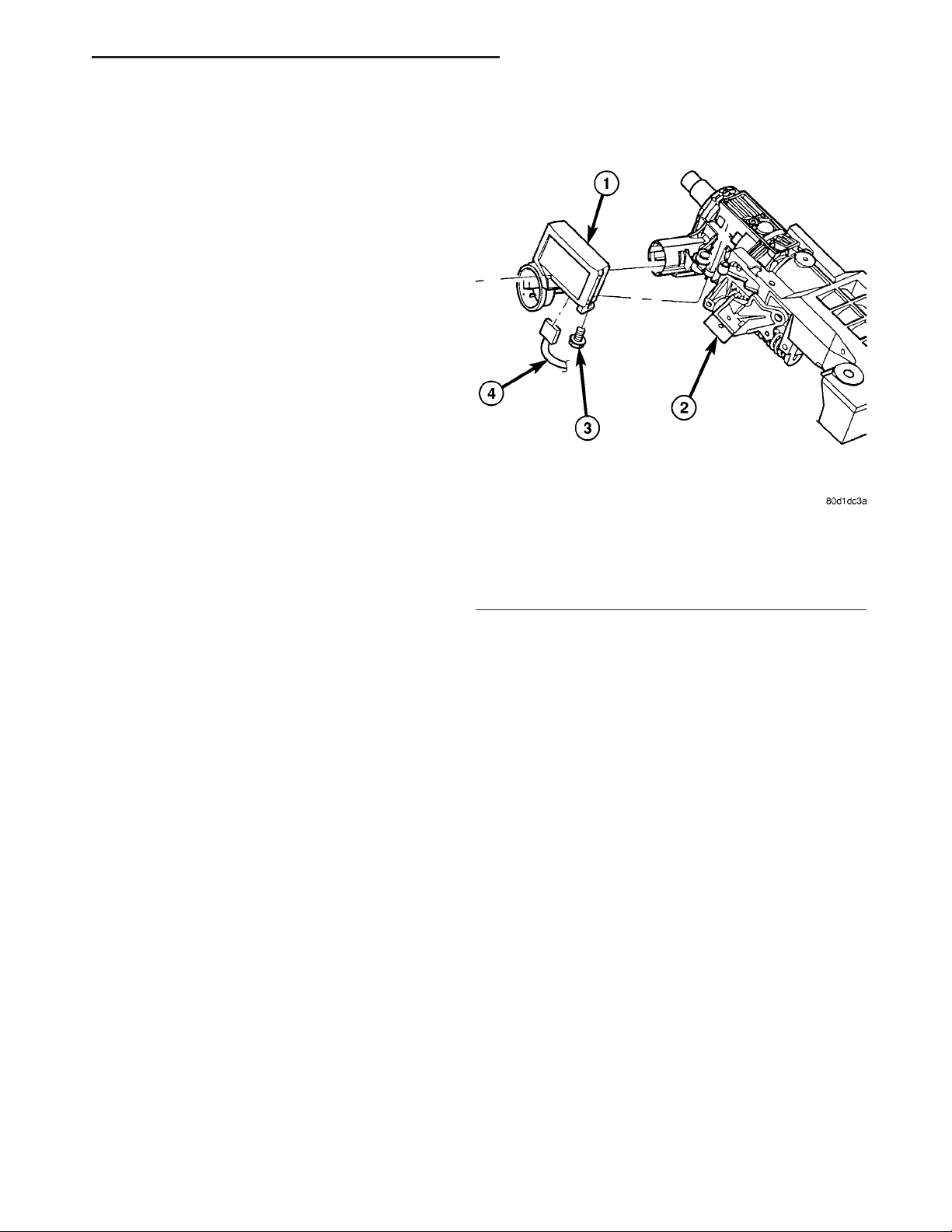
Fig. 8 SENTRY KEY IMMOBILIZER MODULE (SKIM)
1 - SENTRY KEY IMMOBILIZER MODULE (SKIM)
2 - STEERING COLUMN
3 - SCREW
4 - WIRING HARNES
(4) Install the steering column upper and lower
shrouds. Refer to Steering, Column, Shroud, Installation.
(5) Connect the battery negative cable.
TRANSFER CASE CONTROL
MODULE
DESCRIPTION
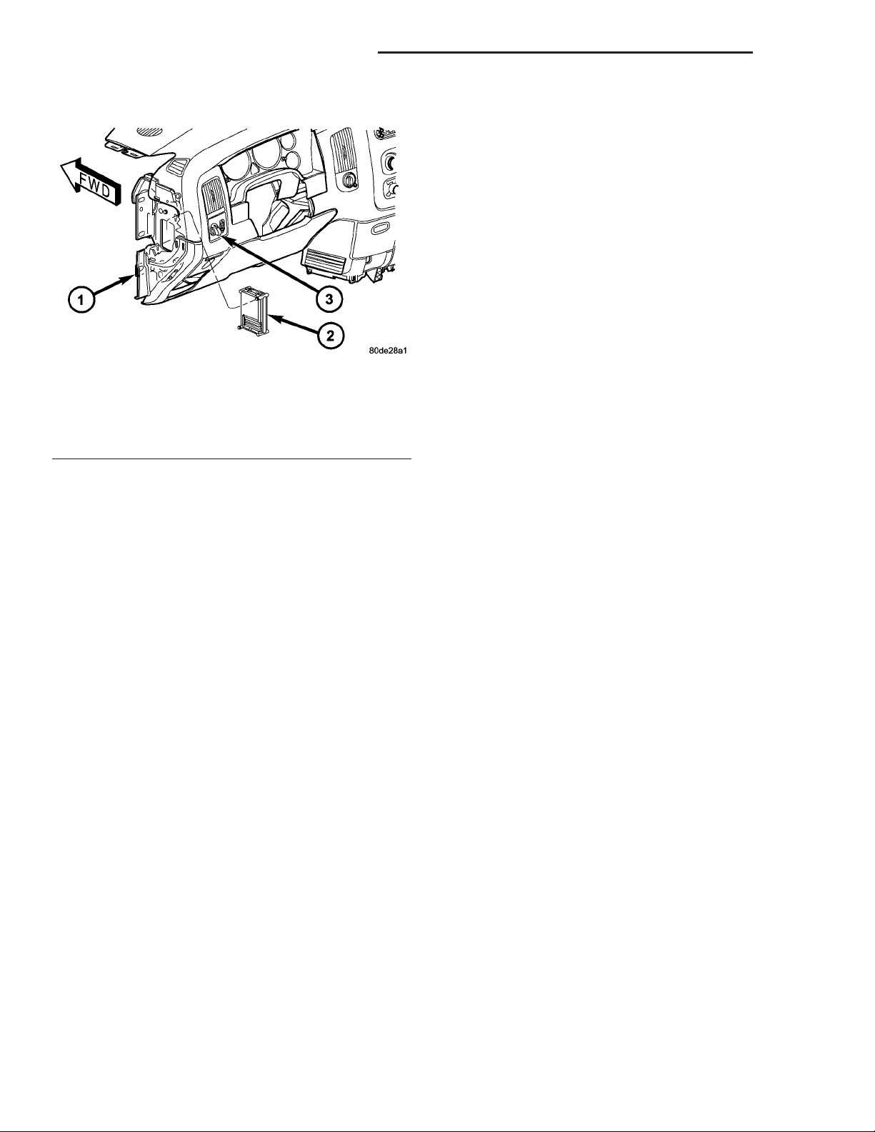
The Transfer Case Control Module (TCCM) (Fig. 9)
is a microprocessor-based assembly, controlling the
4X4 transfer case shift functions via the actuation of
a shift motor and utilizing the feedback of a mode
sensor assembly. Communication is via the PCI serial
bus. Inputs include user selectable 4X4 modes that
include 2WD, 4HI, 4LO, and Neutral. The logic and
driver circuitry is contained in a molded plastic housing with an embedded heat-sink and is located
behind the left side of the lower instrument panel.
OPERATION
(1) Slide the SKIM antenna ring around the ignition switch lock cylinder housing and clip in place
(Fig. 8).
(2) Install the retaining screw.
(3) Connect the steering column wire harness connector to the Sentry Key Immobilizer Module
(SKIM).
The Transfer Case Control Module (TCCM) utilizes
the input from the transfer case mounted mode sensor, the instrument panel mounted selector switch,
and the following information from the vehicle’s PCI
serial bus to determine if a shift is allowed.
• Engine RPM and Vehicle Speed
Page 16
8E - 16 ELECTRONIC CONTROL MODULES DR
TRANSFER CASE CONTROL MODULE (Continued)
module must receive one ignition message that
denotes that the ignition is in the RUN position.
• Sleep Mode will be entered, from the Reduced
Power Mode, when no PCI traffic has been sensed for
20 ±1 seconds. If during Sleep Mode the module
detects PCI bus traffic, it will revert to the Reduced
Power mode while monitoring for ignition messages.
It will remain in this state as long as there is traffic
other than run or start messages, and will return to
Sleep mode if the bus goes without traffic for 20 ±1
seconds.
SHIFT REQUIREMENTS
If the TCCM is in full power mode and at functionality level zero, it uses the following criteria to determine if a shift is allowed.
Fig. 9 Transfer Case Control Module (TCCM)
Location
1 - INSTRUMENT PANEL
2 - TRANSFER CASE CONTROL MODULE (TCCM)
3 - TRANSFER CASE SELECTOR SWITCH
• Diagnostic Requests
• Manual Transmission and Brake Applied
• PRNDL
• Ignition Status
• ABS Messages
Once the TCCM determines that a requested shift
is allowed, it actuates the bi-directional shift motor
as necessary to achieve the desired transfer case
operating mode. The TCCM also monitors the mode
sensor while controlling the shift motor to determine
the status of the shift attempt.
Several items can cause the requested shift not to
be completed. If the TCCM has recognized a fault
(DTC) of some variety, it will begin operation in one
of four Functionality Levels. These levels are:
• Level Zero - Normal Operation.
• Level One - Only Mode Shifts Are Allowed.
• Level Two - Only Mode Shifts and Shifts Into
LOW Are Allowed (No Neutral Shifts Are Allowed).
• Level Three - No Shifts Are Allowed
The TCCM can also be operating in one of three
possible power modes. These power modes are:
• Full Power Mode is the normal operational
mode of the module. This mode is achieved by normal
PCI bus traffic being present and the ignition being
in the RUN position.
• Reduced Power Mode will be entered when
the ignition has been powered off. In this state, the
module will shut down power supplied to external
devices, and to electronic interface inputs and outputs. From this state the module can enter either
Sleep Mode or Full Power Mode. To enter this mode,
the module must receive an ignition message denoting that the ignition is off, or not receive any messages for 5 ±0.5 seconds. To exit this mode, the
If any of the driver controllable conditions are not
met once the shift request is recognized, the TCCM
will solidly illuminate the source position’s LED and
flash the desired position’s LED for all shifts except
NEUTRAL. The NEUTRAL shift LED strategy will
be discussed later.
Mode shifts will be allowed regardless of transmission gear or vehicle speed, whenever the following
conditions are met:
• Front and rear wheel speed are within 21 km/hr
(13 mph).
• A change in the Selector switch state indicates
that a mode shift has been requested.
• A valid mode sensor signal is being sensed by
the TCCM.
• Proper transmit/receive messages are occurring
on the PCI bus.
• Ignition key switch is in the RUN position.
Range shifts will be allowed only if all of the following conditions are met:
• Front and rear wheel speed are within 21 km/hr
(13 mph).
• A change in the Selector Switch state indicating
a range shift has been requested.
• Transmission in NEUTRAL signal must be recognized for at least 1.5 seconds ±100 msec. (Automatic transmissions only)
• Proper transmit/receive messages are occurring
on the PCI bus.
• Clutch signal is recognized for 500 msec ± 50
msec (Manual transmissions only).
• Vehicle speed is less than or equal to 4.8 km/hr
(3 miles per hour).
• Ignition key switch is in the RUN position.
• A valid mode sensor signal is being sensed by
the TCCM.
A shift into transfer case Neutral will be
allowed only if all of the following conditions are met:
• Front and rear wheel speed are within 21 km/hr
(13 mph).
Page 17

DR ELECTRONIC CONTROL MODULES 8E - 17
TRANSFER CASE CONTROL MODULE (Continued)
• The recessed Neutral Selection switch has been
depressed continuously for 4.0 seconds ±100 msec
while all shift conditions have been continuously met.
• Transmission in NEUTRAL signal recognized
from the bus. (Automatic transmissions only)
• Clutch signal is recognized from the bus (Manual transmissions only).
• Proper message transmissions/receptions are
occurring on the PCI bus.
• Vehicle speed is less than or equal to 4.8 km/hr
(3 miles per hour).
• Ignition key switch is in the RUN position,
engine off.
• Foot Brake is applied.
• A valid mode sensor signal is being sensed by
the TCCM.
A shift out of transfer case Neutral will be
allowed only if all of the following conditions are met:
• Front and rear wheel speed are within 21 km/hr
(13 mph).
• The recessed Neutral Selection switch has been
depressed continuously for 1.0 seconds ±100 msec
while all shift conditions have been continuously met.
• Transmission in NEUTRAL signal recognized
from the bus.(Automatic transmissions only)
• Clutch signal is recognized from the bus (Manual transmissions only).
• Proper message transmissions/receptions are
occurring on the PCI bus.
• Vehicle speed is less than or equal to 4.8 km/hr
(3 miles per hour).
• Ignition key switch is in the RUN position.
• Foot Brake is applied.
• A valid mode sensor signal is being sensed by
the TCCM.
SHIFT SEQUENCES
Once all the driver controllable conditions for the
requested shift have been met, the TCCM begins a
shift timer with a maximum duration of 1 second per
’D’ channel transition. If the shift timer expires
before the TCCM recognizes to correct mode sensor
code, the shift is considered to have been blocked.
The blocked shift will increment the blocked shift
counter by one. The TCCM strategy for handling
blocked shifts will be described later. The process the
TCCM performs for the various shifts will be
described first.
RANGE AND MODE SHIFTS
The process for performing all the range and mode
shifts are the same. The following steps describe the
process.
• Allow time for Selector Switch debounce; 250
msec ±50 msec.
• Extinguish the source gear’s LED while flashing
desired transfer case position’s LED.
• Engage the shift motor for a maximum of 1 second ±100 msec per ’D’ channel transition in the destination gear’s direction while monitoring the mode
sensor channel transitions.
• Disengage the shift motor when the correct
mode sensor code is recognized.
• Solidly illuminate the selected gear’s LED.
• Transmit a bus message that the transfer case
shift is complete.
• If the desired mode sensor code is not received
after the shift timer expires (ie. a blocked or other
condition exists), stop driving the motor and wait for
200 msec ±50 msec. The shift motor is then reversed
in the direction back toward the source gear for up to
1.0 seconds ±100 msec. per ’D’ channel. The TCCM
waits for 2.0 seconds ±50 msec. and repeats the
attempt to shift to the desired position.
The exception to the preceding sequence is when a
shift from 4L to 2WD/AWD is requested. If 2WD/
AWD is requested from the 4L position, the transfer
case is first driven to the 4H position. If the 4H position is reached, the transfer case is then driven back
to the 2WD/AWD position and the shift is considered
complete. If the transfer case does not reach any the
4H position, but is in the 2WD/AWD ’D’ channel, or
the 2WD/AWD between gear position on the 4H side
of 2WD/AWD, the shift is also considered complete.
SHIFT OUT OF NEUTRAL
• Extinguish the Neutral LED.
• Engage the shift motor for a maximum of 1 sec-
ond ±100 msec toward the transfer case 4H mode
position while monitoring the mode sensor channel
transitions.
• Disengage the shift motor when the correct
mode sensor code is recognized.
• Extinguish the Neutral LED.
• Transmit a bus message that the transfer case
shift is complete.
• If the desired mode sensor code is not received
after the shift timer expires (ie. a blocked or other
condition exists), stop driving the motor and wait for
200 msec ±50 msec. The shift motor is then reversed
in the direction back toward the source gear for up to
1.0 seconds 100 msec. The TCCM waits for 2.0 seconds ±50 msec. and repeats the attempt to shift to
the desired position.
• When the Neutral button is released, if the 4H
position is the desired position, the shift is complete.
Illuminate the 4H LED.
• Otherwise when the Neutral button is released,
if all of the shift requirements are being met then
engage the shift motor towards the desired position
for 1 second ±100 msec per ’D’ channel. (if require-
Page 18

8E - 18 ELECTRONIC CONTROL MODULES DR
TRANSFER CASE CONTROL MODULE (Continued)
ments for shifting are not met, illuminate the 4H
LED and flash the destination LED as an indication
to the driver that all of the driver controllable shift
conditions are not being met). If this requires
another range or mode shift, begin the range/mode
shift process.
• If the desired mode sensor code is not received
after the shift timer expires (i.e. a blocked or other
condition exists), refer to the section on Blocked Shift
Strategy.
BLOCKED SHIFT STRATEGY
When a shift is commanded, the shift motor will be
driven towards its destination position, except in the
case of shifting out of Neutral if 4L was selected (the
transfer case will shift to the 4H position first, before
proceeding to 4L). If the shift is blocked on the way
to the destination, the TCCM may attempt to drive
the motor back to the original position. This process
will be allowed to occur 5 times. If the transfer case
has reached a non-NEUTRAL ’D’ channel during the
shift re-attempts, the LED for the achieved gear position is illuminated and the shift attempts are
stopped. To re-attempt the desired shift, the selector
switch will need to be rotated to the current position
until the switch debounce timer expires then a shift
will need to be requested again.
At the end of the 5th blocked attempt, the shift
motor is driven towards the last known ’D’ channel
position. If this motor drive allows the transfer case
to reach the 2WD/AWD ’D’ channel, or the 2WD/AWD
between gear position on the 4H side of 2WD/AWD,
the shift is considered complete and the shift
attempts are ended.
If the mode sensor is in the NEUTRAL region at
the expiration of the shift timer, the TCCM will continue to make the shift attempts according to the
blocked shift strategy independent of whether or not
the driver controlled conditions are met.
For shifts from NEUTRAL, if all 5 attempts fail to
reach the desired position (which by default is 4H),
the motor will be driven to stall in the direction of
4H or 4L, depending on the achieved position. If the
transfer case has reached the 2WD/AWD or 4L
between gear position nearest the NEUTRAL positions and the shift conditions are no longer being
met, the transfer case will be driven toward the corresponding ’D’ channel. Otherwise, the transfer case
will be driven in the direction opposite the last
attempt with the desired target being 4H or 4L.
If the transfer case reaches the 2WD/AWD ’D’
channel when being driven in the 4H direction, then
one final 1.0 second drive toward 4H is attempted. If
the transfer case then reaches any of the 4H positions, the shift is considered complete and the 4H
LED is illuminated. If the transfer case is still the
2WD/AWD position, the shift is considered complete
and the 2WD/AWD LED is illuminated.
NOTE: If after the 5th blocked shift and reversal
attempt, if the transfer case position is in the NEUTRAL region, shift attempts will continue until a
non-NEUTRAL ’D’ channel is reached.
SHIFT REVERSAL TARGETS
If the shift timer expires (1 second per ’D’ channel)
and the transfer case has not reached the desired
position, all shifts will attempt to return to their
original position with the exceptions of:
• If the intended shift is going to the High rail
from Low and can’t make it, but it can make the
2WD/AWD position, the motor stops at that position.
The TCCM will not attempt to cross back over NEUTRAL if it does not have to. This means that there
was a block on the first attempt to go to 4H and the
transfer case has made it through NEUTRAL to a
known good position, then the motor will go back
only to the 2WD/4WD position and execute the
remainder of the attempts from there.
• For shifts out of NEUTRAL, any time a shift is
commanded out of NEUTRAL, the system needs to
get out. The TCCM should never go to NEUTRAL
unless the driver is commanding it and all required
conditions are being met
ENCODER DRIFT CORRECTION
Whenever a shift is completed, the TCCM stores
the position in memory as the transfer case’s
intended position. The TCCM continuously monitors
the mode sensor and if the mode sensor drifts toward
into a NEUTRAL region sensor position for 2.0 seconds, the TCCM will perform a motor drive to correct
the drift. The transfer case will be driven toward the
intended position for 1.0 seconds 100 msec. The
TCCM will wait for 2.0 seconds ±50 msec. and repeat
the attempt to shift to the desired position. This will
continue until the intended position is reached.
SHIFT MOTOR BRAKING
Two modes of shift motor braking are employed to
improve shift performance, static and dynamic. Static
shift motor braking is utilized under the following
conditions:
• Whenever the transfer case is in the 2WD/AWD
or 4L ’D’ channel position.
• Whenever an invalid mode sensor code is
present.
Static motor braking is achieved by applying +12V
on both shift motor wires.
NOTE: Static Shift Motor Braking is independent of
ignition key position.
Page 19
DR ELECTRONIC CONTROL MODULES 8E - 19
TRANSFER CASE CONTROL MODULE (Continued)
SHIFT ATTEMPT LIMIT
To protect the transfer case system, the TCCM will
impose a limit on the number of shifts that can occur
over a calibrated time period. The system will monitor
the number of ’D’ channel segment transitions that
occur in any 30 second time period. If the number of
segment transitions is 30 or greater, the system will go
into a default mode. The default mode of operation for
shifting is that the number of allowed ’D’ channel transitions permitted to occur will be 3 over each 15 second
±100 msec calibrated window of time. After 5 minutes
±100 msec, the motor can be assumed to have cooled
down and the system will revert to normal operation.
The following rules also apply to the shift limit:
• The attempt limit will not prevent shifts coming
out of NEUTRAL, they will be allowed regardless of
the counter/timer.
• Any shift that is in progress when the counter
reaches a maximum count in time will be allowed to
complete before the default mode is entered. D-channel transitions during this period will not be counted
towards the default mode limit.
• A block, regardless of the direction, whether
towards destination or back towards reversal target
(shift timer expiring), will count as a value of 2 transitions towards the 30 segment transitions to go into
default mode as defined above. Current attempt limit
values are 30 transitions in 30 seconds and default
mode values are 3 transitions every 15 seconds for 5
minutes.
TRANSMISSION CONTROL
MODULE
DESCRIPTION
The Transmission Control Module (TCM) (Fig. 10)
may be sub-module within the Powertrain Control
Module (PCM) or a standalone module, depending on
the vehicle engine. The PCM, and TCM when
equipped, is located at the right rear of the engine
compartment, near the right inner fender.
OPERATION
The Transmission Control Module (TCM) controls
all electronic operations of the transmission. The
TCM receives information regarding vehicle operation from both direct and indirect inputs, and selects
the operational mode of the transmission. Direct
inputs are hardwired to, and used specifically by the
TCM. Indirect inputs are shared with the TCM via
the vehicle communication bus.
Some examples of direct inputs to the TCM are:
• Battery (B+) voltage
• Ignition “ON” voltage
• Transmission Control Relay (Switched B+)
1 - RIGHT FENDER
2 - TRANSMISSION CONTROL MODULE
3 - POWERTRAIN CONTROL MODULE
• Throttle Position Sensor
• Crankshaft Position Sensor
• Transmission Range Sensor
• Pressure Switches
• Transmission Temperature Sensor
• Input Shaft Speed Sensor
• Output Shaft Speed Sensor
• Line Pressure Sensor
Some examples of indirect inputs to the TCM are:
• Engine/Body Identification
• Manifold Pressure
• Target Idle
• Torque Reduction Confirmation
• Engine Coolant Temperature
• Ambient/Battery Temperature
• DRBIIIt Scan Tool Communication
Based on the information received from these various inputs, the TCM determines the appropriate
shift schedule and shift points, depending on the
present operating conditions and driver demand.
This is possible through the control of various direct
and indirect outputs.
Some examples of TCM direct outputs are:
• Transmission Control Relay
• Solenoids
• Torque Reduction Request
Some examples of TCM indirect outputs are:
• Transmission Temperature (to PCM)
• PRNDL Position (to BCM)
In addition to monitoring inputs and controlling
outputs, the TCM has other important responsibilities and functions:
• Storing and maintaining Clutch Volume Indexes
(CVI)
Storing and selecting appropriate Shift Schedules
•
• System self-diagnostics
• Diagnostic capabilities (with DRBIIIt scan tool)
Fig. 10 PCM/TCM Location
Page 20

8E - 20 ELECTRONIC CONTROL MODULES DR
TRANSMISSION CONTROL MODULE (Continued)
NOTE: If the TCM has been replaced, the “Quick Learn
Procedure” must be performed. (Refer to 8 - ELECTRICAL/ELECTRONIC CONTROL MODULES/TRANSMISSION CONTROL MODULE - STANDARD PROCEDURE)
BATTERY FEED
A fused, direct battery feed to the TCM is used for
continuous power. This battery voltage is necessary
to retain memory in the TCM. When the battery (B+)
is disconnected, this memory is lost. When the battery (B+) is restored, this memory loss is detected by
the TCM and a Diagnostic Trouble Code (DTC) is set.
CLUTCH VOLUME INDEXES (CVI)
An important function of the TCM is to monitor
Clutch Volume Indexes (CVI). CVIs represent the volume of fluid needed to compress a clutch pack.
The TCM monitors gear ratio changes by monitoring the Input and Output Speed Sensors. The Input,
or Turbine Speed Sensor sends an electrical signal to
the TCM that represents input shaft rpm. The Output Speed Sensor provides the TCM with output
shaft speed information.
By comparing the two inputs, the TCM can determine transmission gear position. This is important to
the CVI calculation because the TCM determines
CVIs by monitoring how long it takes for a gear
change to occur (Fig. 11).
Gear ratios can be determined by using the
DRBIIIt Scan Tool and reading the Input/Output
Speed Sensor values in the “Monitors” display. Gear
ratio can be obtained by dividing the Input Speed
Sensor value by the Output Speed Sensor value.
For example, if the input shaft is rotating at 1000
rpm and the output shaft is rotating at 500 rpm,
then the TCM can determine that the gear ratio is
2:1. In direct drive (3rd gear), the gear ratio changes
to 1:1. The gear ratio changes as clutches are applied
and released. By monitoring the length of time it
takes for the gear ratio to change following a shift
request, the TCM can determine the volume of fluid
used to apply or release a friction element.
The volume of transmission fluid needed to apply
the friction elements are continuously updated for
adaptive controls. As friction material wears, the volume of fluid need to apply the element increases.
Certain mechanical problems within the input
clutch assembly can cause inadequate or out-of-range
element volumes. Also, defective Input/Output Speed
Sensors and wiring can cause these conditions. The
following chart identifies the appropriate clutch volumes and when they are monitored/updated:
1 - OUTPUT SPEED SENSOR
2 - OUTPUT SHAFT
3 - CLUTCH PACK
4 - SEPARATOR PLATE
5 - FRICTION DISCS
6 - INPUT SHAFT
7 - INPUT SPEED SENSOR
8 - PISTON AND SEAL
SHIFT SCHEDULES
As mentioned earlier, the TCM has programming that
allows it to select a variety of shift schedules. Shift
schedule selection is dependent on the following:
• Shift lever position
• Throttle position
• Engine load
• Fluid temperature
• Software level
As driving conditions change, the TCM appropriately adjusts the shift schedule. Refer to the following chart to determine the appropriate operation
expected, depending on driving conditions.
Fig. 11 Example of CVI Calculation
CLUTCH VOLUMES
Clutch When Updated
L/R
2C
2-1 or 3-1
downshift
3-2 kickdown
shift
Proper Clutch
Volume
45 to 134
25 to 85
OD 2-3 upshift 30 to 100
4C 3-4 upshift 30 to 85
UD
4-3 kickdown
shift
30 to 100
Page 21

DR ELECTRONIC CONTROL MODULES 8E - 21
TRANSMISSION CONTROL MODULE (Continued)
Schedule Condition Expected Operation
Extreme Cold Oil temperature below -16° F -Park, Reverse, Neutral and 1st and
3rd gear only in D position, 2nd
gear only in Manual 2 or L
-No EMCC
Super Cold Oil temperature between -12° F and
10° F
Cold Oil temperature between 10° F and
36° F
Warm Oil temperature between 40° F and
80° F
Hot Oil temperature between 80° F and
240° F
Overheat Oil temperature above 240° F or
engine coolant temperature above
244° F
- Delayed 2-3 upshift
- Delayed 3-4 upshift
- Early 4-3 coastdown shift
- High speed 4-2, 3-2, 2-1 kickdown
shifts are prevented
-Shifts at high throttle openings willl
be early.
- No EMCC
-Shift schedule is the same as
Super Cold except that the 2-3
upshifts are not delayed.
- Normal operation (upshift,
kickdowns, and coastdowns)
- No EMCC
- Normal operation (upshift,
kickdowns, and coastdowns)
- Normal EMCC operation
- Delayed 2-3 upshift
- Delayed 3-4 upshift
- 3rd gear FEMCC from 30-48 mph
- 3rd gear PEMCC above 35 mph
- Above 25 mph the torque
converter will not unlock unless the
throttle is closed or if a wide open
throttle 2nd PEMCC to 1 kickdown
is made
STANDARD PROCEDURE
STANDARD PROCEDURE - TCM QUICK LEARN
The quick learn procedure requires the use of the
DRBt scan tool.
This program allows the electronic transmission
system to recalibrate itself. This will provide the
proper transmission operation. The quick learn procedure should be performed if any of the following
procedures are performed:
• Transmission Assembly Replacement
• Transmission Control Module Replacement
• Solenoid Pack Replacement
• Clutch Plate and/or Seal Replacement
• Valve Body Replacement or Recondition
To perform the Quick Learn Procedure, the following conditions must be met:
• The brakes must be applied
• The engine speed must be above 500 rpm
• The throttle angle (TPS) must be less than 3
degrees
• The shift lever position must stay in PARK until
prompted to shift to overdrive
• The shift lever position must stay in overdrive
after the Shift to Overdrive prompt until the DRBt
indicates the procedure is complete
• The calculated oil temperature must be above
60° and below 200°
STANDARD PROCEDURE - DRIVE LEARN
When a transmission is repaired and a Quick
Learn procedure has been performed on the Transmission Control Module (TCM), the following Drive
Learn procedure can be performed to fine tune any
shifts which are particularly objectionable.
NOTE: It is not necessary to perform the complete
Drive Learn procedure every time the TCM is Quick
Learned. Perform only the portions which target the
objectionable shift.
Page 22

8E - 22 ELECTRONIC CONTROL MODULES DR
TRANSMISSION CONTROL MODULE (Continued)
LEARN A SMOOTH 1ST NEUTRAL TO DRIVE SHIFT
Perform this procedure only if the complaint is for
a delayed or harsh shift the first time the transmission is put into gear after the vehicle is allowed to
set with the engine not running for at least 10 minutes. Use the following steps to have the TCM learn
the 1st N-D UD CVI.
NOTE: The transmission oil temperature must be
between 80 - 110°F (27 - 43°C).
(1) Start the engine only when the engine and
ignition have been off for at least ten (10) minutes.
(2) With the vehicle at a stop and the service
brake applied, record the 1st N-D UD CVI while performing a Neutral to Drive shift. The 1st N-D UD
CVI accounts for air entrapment in the UD clutch
that may occur after the engine has been off for a
period of time.
(3) Repeat Step 1 and Step 2 until the recorded 1st
N-D UD CVI value stabilizes.
NOTE: It is important that this procedure be performed when the transmission temperature is
between 80 - 110°F (27 - 43°C). If this procedure
takes too long to complete fully for the allowed
transmission oil temperature, the vehicle may be
returned to the customer with an explanation that
the shift will improve daily during normal vehicle
usage. The TCM also learns at higher oil temperatures, but these values (line pressure correction
values) are not available for viewing on the DRBT
III.
LEARN A SMOOTH NEUTRAL TO DRIVE GARAGE
SHIFT
Perform this procedure if the complaint is for a
delayed or harsh shift when the transmission is put
into gear after the vehicle has had its first shift. Use
the following steps to have the TCM learn the Norm
N-D UD CVI.
NOTE: The transmission oil temperature must be
between 80 - 110°F (27 - 43°C) to learn the UD CVI.
Additional learning occurs at temperatures as low
as 0°F and as high as 200°F. This procedure may be
performed at any temperature that experiences poor
shift quality. Although the UD CVI may not change,
shift quality should improve.
(1) Start the vehicle engine and shift to drive.
(2) Move the vehicle forward to a speed of at least
16 km/h (10 MPH) and come to a stop. This ensures
no air is present in the UD hydraulic circuit.
(3) Perform repeated N-D shifts at a stop while
pausing in Neutral for at least 2-3 seconds and mon-
itor Norm N-D UD CVI volume until the value stabilizes. The value will change during the N-D shift.
This is normal since the UD value is different for the
N-D shift then the normal value shown which is used
for 4-3 coastdown and kickdowns. Perform repeated
shifts in this temperature range until the Norm N-D
UD CVI value stabilizes and the N-D shifts become
smooth.
LEARN THE 1ST 2-3 SHIFT AFTER A RESTART OR
SHIFT TO REVERSE
Use the following steps to have the TCM learn the
1st 2-3 shift OD CVI.
NOTE: The transmission oil temperature must be
above 80°F (27°C).
(1) With the vehicle engine running, select reverse
gear for over 2 seconds.
(2) Shift the transmission to Drive and accelerate
the vehicle from a stop at a steady 15 degree throttle
opening and perform a 2-3 shift while noting the 1st
2-3 OD CVI.
(3) Repeat Step 1 and Step 2 until the 1st 2-3
upshift becomes smooth and the 1st 2-3 OD CVI stabilizes.
LEARN A SMOOTH 2-3 AND 3-4 UPSHIFT
NOTE: The transmission oil temperature must be
above 110°F (43°C).
Use the following steps to have the TCM learn the
OD and 4C CVI’s.
(1) Accelerate the vehicle from a stop at a steady
15 degree throttle opening and perform multiple 1-2,
2-3, and 3-4 upshifts. The 2nd 2-3 shift following a
restart or shift to reverse will be shown during the
shift as a value between the 1st 2-3 OD CVI and the
normal OD CVI. Updates to the normal OD CVI will
occur after the 2nd shift into 3rd gear, following a
restart or shift to reverse.
(2) Repeat Step 1 until the 2-3 and 3-4 shifts
become smooth and the OD and 4C CVI become stable.
LEARN A SMOOTH 4-3 COASTDOWN AND PART
THROTTLE 4-3 KICKDOWN
NOTE: The transmission oil temperature must be
above 110°F (43°C).
Use the following steps to have the TCM learn the
UD shift volume.
(1) At a vehicle speed between 64-97 km/h (40-60
MPH), perform repeated 4-3 kickdown shifts.
Page 23

DR ELECTRONIC CONTROL MODULES 8E - 23
TRANSMISSION CONTROL MODULE (Continued)
(2) Repeat Step 1 until the UD volume becomes
somewhat stable and the shift becomes smooth.
LEARN A SMOOTH 1-2 UPSHIFT AND 3-2
KICKDOWN
Use the following steps to have the TCM learn the
2C shift volume.
NOTE: The transmission oil temperature must be
above 110°F (43°C).
(1) With a vehicle speed below 48 km/h (30 MPH)
and the transmission in 3rd gear, perform multiple
3-2 kickdowns.
(2) Repeat Step 1 until the 3-2 kickdowns become
smooth and the 2C CVI becomes stable.
LEARN A SMOOTH MANUAL 2-1 PULLDOWN
SHIFT AS WELL AS A NEUTRAL TO REVERSE
SHIFT
NOTE: The transmission oil temperature must be
above 110°F (43°C).
Use the following steps to have the TCM learn the
LR volume.
(1) With the vehicle speed around 40-48 km/h
(25-30 MPH) in Manual 2nd, perform manual pulldowns to Low or 1st gear at closed throttle.
(2) Repeat Step 1 until the LR CVI becomes stable
and the manual 2-1 becomes smooth.
LEARN A SMOOTH NEUTRAL TO REVERSE SHIFT
NOTE: The transmission oil temperature must be
above 110°F (43°C).
(1) With the vehicle at a stop, perform Neutral to
Reverse shifts until the shift is smooth. An unlearned
Neutral to Reverse shift may be harsh or exhibit a
double bump.
(2) If any of the shifts are still not smooth after
the clutch volume stabilizes, an internal transmission problem may be present.
LEARN A SMOOTH 4-5 UPSHIFT
NOTE: The transmission oil temperature must be
above 110°F (43°C).
Use the following steps to have the TCM learn the
Alt 2C CVI.
(1) Accelerate the vehicle through 88 km/h
(55mph) at a steady 10-15 degree throttle opening
and perform multiple 4-5 upshifts.
(2) Repeat Step 1 until the 4-5 shift become
smooth and theAlt 2C CVI become stable. There is a
separate 2C volume used and learned for 4-5 shifts,
2CA. It is independent of the 2C CVI learned on 3-2
kickdowns.
Page 24

Page 25

DR ENGINE SYSTEMS 8F - 1
ENGINE SYSTEMS
TABLE OF CONTENTS
page page
BATTERY SYSTEM ......................... 1
CHARGING .............................. 19
BATTERY SYSTEM
TABLE OF CONTENTS
page page
BATTERY SYSTEM
DESCRIPTION ..........................1
OPERATION ............................2
DIAGNOSIS AND TESTING - BATTERY
SYSTEM .............................2
CLEANING .............................4
INSPECTION ...........................6
SPECIFICATIONS ........................6
SPECIAL TOOLS
BATTERY SYSTEM SPECIAL TOOLS .......7
BATTERY
DESCRIPTION ..........................7
DIAGNOSIS AND TESTING - BATTERY .......7
STANDARD PROCEDURE
STANDARD PROCEDURE - BATTERY
CHARGING ...........................8
STANDARD PROCEDURE - BUILT-IN
INDICATOR TEST .....................10
STANDARD PROCEDURE - OPEN-CIRCUIT
VOLTAGE TEST .......................10
STANDARD PROCEDURE - IGNITION-OFF
DRAW TEST .........................11
STARTING............................... 28
STANDARD PROCEDURE - USING MICRO
420 BATTERY TESTER .................12
REMOVAL .............................13
INSTALLATION .........................14
BATTERY HOLDDOWN
DESCRIPTION .........................14
OPERATION ...........................14
REMOVAL .............................14
INSTALLATION .........................14
BATTERY CABLES
DESCRIPTION .........................14
OPERATION ...........................14
DIAGNOSIS AND TESTING - BATTERY
CABLES ............................15
REMOVAL .............................16
INSTALLATION .........................17
BATTERY TRAY
DESCRIPTION .........................17
OPERATION ...........................17
REMOVAL .............................17
INSTALLATION .........................18
BATTERY SYSTEM
DESCRIPTION
A single 12-volt battery is standard factory-installed equipment on gasoline engine equipped models. Diesel engine equipped vehicles utilize two
12-volt batteries connected in parallel. All of the components of the battery system are located within the
engine compartment of the vehicle. The battery system for this vehicle, covers the following related components, which are covered in further detail later in
this section of the service manual:
• Battery - The storage battery provides a reli-
able means of storing a renewable source of electrical
energy within the vehicle.
• Battery Cables - The battery cables connect
the battery terminal posts to the vehicle electrical
system.
• Battery Holddown - The battery holddown
hardware secures the battery in the battery tray in
the engine compartment.
• Battery Tray - The battery tray provides a
secure mounting location in the vehicle for the battery and an anchor point for the battery holddown
hardware.
Page 26

8F - 2 BATTERY SYSTEM DR
BATTERY SYSTEM (Continued)
For battery system maintenance schedules and
jump starting procedures, see the owner’s manual in
the vehicle glove box. Optionally, refer to the Lubrication and Maintenance section of this manual for
the proper battery jump starting procedure. While
battery charging can be considered a maintenance
procedure, the battery charging procedure and
related information are located later in this section of
the service manual. This was done because the battery must be fully-charged before any battery system
diagnosis or testing procedures can be performed.
OPERATION
The battery system is designed to provide a safe,
efficient, reliable and mobile means of delivering and
storing electrical energy. This electrical energy is
required to operate the engine starting system, as
well as to operate many of the other vehicle accessory systems for limited durations while the engine
and/or the charging system are not operating. The
battery system is also designed to provide a reserve
of electrical energy to supplement the charging system for short durations while the engine is running
and the electrical current demands of the vehicle
exceed the output of the charging system. In addition
to delivering, and storing electrical energy for the
vehicle, the battery system serves as a capacitor and
voltage stabilizer for the vehicle electrical system. It
absorbs most abnormal or transient voltages caused
by the switching of any of the electrical components
or circuits in the vehicle.
DIAGNOSIS AND TESTING - BATTERY SYSTEM
The battery, starting, and charging systems in the
vehicle operate with one another and must be tested
as a complete system. In order for the engine to start
and the battery to maintain its charge properly, all of
the components that are used in these systems must
perform within specifications. It is important that
the battery, starting, and charging systems be thoroughly tested and inspected any time a battery needs
to be charged or replaced. The cause of abnormal battery discharge, overcharging or early battery failure
must be diagnosed and corrected before a battery is
replaced and before a vehicle is returned to service.
The service information for these systems has been
separated within this service manual to make it easier to locate the specific information you are seeking.
However, when attempting to diagnose any of these
systems, it is important that you keep their interdependency in mind.
The diagnostic procedures used for the battery,
starting, and charging systems include the most
basic conventional diagnostic methods, to the more
sophisticated On-Board Diagnostics (OBD) built into
the Powertrain Control Module (PCM). Use of an
induction-type milliampere ammeter, a volt/ohmmeter, a battery charger, a carbon pile rheostat (load
tester), a 12-volt test lamp and/or special service
tools may be required. All OBD-sensed systems are
monitored by the PCM. Each monitored circuit is
assigned a Diagnostic Trouble Code (DTC). The PCM
will store a DTC in electronic memory for any failure
it detects. Always check the PCM for stored trouble
codes before returning the vehicle to service. Refer to
Charging System for the proper charging system test
procedures. Refer to Starting System for the proper
starting system test procedures.
MICRO 420 BATTERY TESTER
The Micro 420 automotive battery tester is
designed to help the dealership technician diagnose a
defective battery. Follow the instruction manual supplied with the tester to properly diagnose a battery.
If the instruction manual is not available, refer to
the standard procedure in this section, which
includes the directions for using the Micro 420 battery tester.
Page 27

DR BATTERY SYSTEM 8F - 3
BATTERY SYSTEM (Continued)
BATTERY SYSTEM DIAGNOSIS
CONDITION POSSIBLE CAUSES CORRECTION
THE BATTERY SEEMS
WEAK OR DEAD WHEN
ATTEMPTING TO START
THE ENGINE.
1. The electrical system
ignition-off draw is excessive.
2. The charging system is
faulty.
3. The battery is discharged. 3. Determine the battery state-of-charge using the
4. The battery terminal
connections are loose or
corroded.
5. The battery has an
incorrect size or rating for
this vehicle.
6. The battery is faulty. 6. Determine the battery cranking capacity using
7. The starting system is
faulty.
8. The battery is physically
damaged.
1. Refer to the IGNITION-OFF DRAW TEST
Standard Procedure for the proper test
procedures. Repair the excessive ignition-off
draw, as required.
2. Determine if the charging system is performing
to specifications. Refer to Charging System for
additional charging system diagnosis and testing
procedures. Repair the faulty charging system, as
required.
Micro 420 battery tester. Refer to the Standard
Procedures in this section for additional test
procedures. Charge the faulty battery, as
required.
4. Refer to Battery Cables for the proper battery
cable diagnosis and testing procedures. Clean
and tighten the battery terminal connections, as
required.
5. Refer to Battery System Specifications for the
proper size and rating. Replace an incorrect
battery, as required.
the Micro 420 battery tester. Refer to the
Standard Procedures in this section for additional
test procedures. Replace the faulty battery, as
required.
7. Determine if the starting system is performing
to specifications. Refer to Starting System for the
proper starting system diagnosis and testing
procedures. Repair the faulty starting system, as
required.
8. Inspect the battery for loose terminal posts or a
cracked and leaking case. Replace the damaged
battery, as required.
Page 28

8F - 4 BATTERY SYSTEM DR
BATTERY SYSTEM (Continued)
BATTERY SYSTEM DIAGNOSIS
CONDITION POSSIBLE CAUSES CORRECTION
THE BATTERY STATE OF
CHARGE CANNOT BE
MAINTAINED.
1. The battery has an
incorrect size or rating for
this vehicle.
2. The battery terminal
connections are loose or
corroded.
3. The electrical system
ignition-off draw is excessive.
4. The battery is faulty. 4. Test the battery using the Micro 420 battery
5. The starting system is
faulty.
6. The charging system is
faulty.
7. Electrical loads exceed the
output of the charging
system.
8. Slow driving or prolonged
idling with high-amperage
draw systems in use.
1. Refer to Battery System Specifications for the
proper specifications. Replace an incorrect
battery, as required.
2. Refer to Battery Cable for the proper cable
diagnosis and testing procedures. Clean and
tighten the battery terminal connections, as
required.
3. Refer to the IGNITION-OFF DRAW TEST
Standard Procedure for the proper test
procedures. Repair the faulty electrical system, as
required.
tester. Refer to Standard Procedures for
additional test procedures. Replace the faulty
battery, as required.
5. Determine if the starting system is performing
to specifications. Refer to Starting System for the
proper starting system diagnosis and testing
procedures. Repair the faulty starting system, as
required.
6. Determine if the charging system is performing
to specifications. Refer to Charging System for
additional charging system diagnosis and testing
procedures. Repair the faulty charging system, as
required.
7. Inspect the vehicle for aftermarket electrical
equipment which might cause excessive electrical
loads.
8. Advise the vehicle operator, as required.
THE BATTERY WILL NOT
ACCEPT A CHARGE.
1. The battery is faulty. 1. Test the battery using the Micro 420 battery
ABNORMAL BATTERY DISCHARGING
Any of the following conditions can result in abnor-
mal battery discharging:
1. A faulty or incorrect charging system component. Refer to Charging System for additional charging system diagnosis and testing procedures.
2. A faulty or incorrect battery. Use Micro 420 battery tester and refer to Battery System for additional
battery diagnosis and testing procedures.
3. A faulty circuit or component causing excessive
ignition-off draw.
4. Electrical loads that exceed the output of the
charging system. This can be due to equipment
tester. Charge or replace the faulty battery, as
required.
installed after manufacture, or repeated short trip
use.
5. A faulty or incorrect starting system component.
Refer to Starting System for the proper starting system diagnosis and testing procedures.
6. Corroded or loose battery posts and/or terminal
clamps.
7. Slow driving speeds (heavy traffic conditions) or
prolonged idling, with high-amperage draw systems
in use.
CLEANING
The following information details the recommended
cleaning procedures for the battery and related com-
Page 29

DR BATTERY SYSTEM 8F - 5
BATTERY SYSTEM (Continued)
ponents. In addition to the maintenance schedules
found in this service manual and the owner’s manual, it is recommended that these procedures be performed any time the battery or related components
must be removed for vehicle service.
(1) Clean the battery cable terminal clamps of all
corrosion. Remove any corrosion using a wire brush
or a post and terminal cleaning tool, and a sodium
bicarbonate (baking soda) and warm water cleaning
solution (Fig. 1).
Fig. 1 Clean Battery Cable Terminal Clamp - Typical
1 - TERMINAL BRUSH
2 - BATTERY CABLE
(2) Clean the battery tray and battery holddown
hardware of all corrosion. Remove any corrosion
using a wire brush and a sodium bicarbonate (baking
soda) and warm water cleaning solution. Paint any
exposed bare metal.
(3) If the removed battery is to be reinstalled,
clean the outside of the battery case and the top
cover with a sodium bicarbonate (baking soda) and
warm water cleaning solution using a stiff bristle
parts cleaning brush to remove any acid film (Fig. 2).
Rinse the battery with clean water. Ensure that the
cleaning solution does not enter the battery cells
through the vent holes. If the battery is being
replaced, refer to Battery System Specifications for
the factory-installed battery specifications. Confirm
that the replacement battery is the correct size and
has the correct ratings for the vehicle.
(4) Clean the battery thermal guard with a sodium
bicarbonate (baking soda) and warm water cleaning
solution using a stiff bristle parts cleaning brush to
remove any acid film.
Fig. 2 Clean Battery - Typical
1 - CLEANING BRUSH
2 - WARM WATER AND BAKING SODA SOLUTION
3 - BATTERY
(5) Clean any corrosion from the battery terminal
posts with a wire brush or a post and terminal
cleaner, and a sodium bicarbonate (baking soda) and
warm water cleaning solution (Fig. 3).
Fig. 3 Clean Battery Terminal Post - Typical
1 - TERMINAL BRUSH
2 - BATTERY CABLE
3 - BATTERY
Page 30

8F - 6 BATTERY SYSTEM DR
BATTERY SYSTEM (Continued)
INSPECTION
The following information details the recommended
inspection procedures for the battery and related
components. In addition to the maintenance schedules found in this service manual and the owner’s
manual, it is recommended that these procedures be
performed any time the battery or related components must be removed for vehicle service.
(1) Inspect the battery cable terminal clamps for
damage. Replace any battery cable that has a damaged or deformed terminal clamp.
(2) Inspect the battery tray and battery holddown
hardware for damage. Replace any damaged parts.
(3) Slide the thermal guard off of the battery case
(if equipped). Inspect the battery case for cracks or
other damage that could result in electrolyte leaks.
Also, check the battery terminal posts for looseness.
Batteries with damaged cases or loose terminal posts
must be replaced.
(4) Inspect the battery thermal guard (if equipped)
for tears, cracks, deformation or other damage.
Replace any battery thermal guard that has been
damaged.
(5) Inspect the battery built-in test indicator sight
glass (if equipped) for an indication of the battery
condition. If the battery is discharged, charge as
required. Refer to Standard Procedures for the
proper battery built-in indicator test procedures. Also
refer to Standard Procedures for the proper battery
charging procedures.
SPECIFICATIONS
The battery Group Size number, the Cold Cranking
Amperage (CCA) rating, and the Reserve Capacity
(RC) rating or Ampere-Hours (AH) rating can be
found on the original equipment battery label. Be
certain that a replacement battery has the correct
Group Size number, as well as CCA, and RC or AH
ratings that equal or exceed the original equipment
specification for the vehicle being serviced. Battery
sizes and ratings are discussed in more detail below.
• Group Size - The outside dimensions and ter-
minal placement of the battery conform to standards
established by the Battery Council International
(BCI). Each battery is assigned a BCI Group Size
number to help identify a correctly-sized replacement.
• Cold Cranking Amperage - The Cold Crank-
ing Amperage (CCA) rating specifies how much current (in amperes) the battery can deliver for thirty
seconds at -18° C (0° F). Terminal voltage must not
fall below 7.2 volts during or after the thirty second
discharge period. The CCA required is generally
higher as engine displacement increases, depending
also upon the starter current draw requirements.
• Reserve Capacity - The Reserve Capacity (RC)
rating specifies the time (in minutes) it takes for battery terminal voltage to fall below 10.5 volts, at a
discharge rate of 25 amperes. RC is determined with
the battery fully-charged at 26.7° C (80° F). This rating estimates how long the battery might last after a
charging system failure, under minimum electrical
load.
• Ampere-Hours - The Ampere-Hours (AH) rat-
ing specifies the current (in amperes) that a battery
can deliver steadily for twenty hours, with the voltage in the battery not falling below 10.5 volts. This
rating is also sometimes identified as the twentyhour discharge rating.
BATTERY CLASSIFICATIONS & RATINGS
Part Number
56029449AB 65 600 120 Minutes 66 300
56029451AB 65 750 150 Minutes 75 375
56028450AA 65 600 120 Minutes 66 300
56028452AA 65 750 150 Minutes 75 375
56028452AB 65 700 130 Minutes 70 350
56029396AA 65 700 130 Minutes 70 350
56029382AA 65 700 130 Minutes 70 350
BCI Group Size
Classification
Cold Cranking
Amperage
Reserve
Capacity
Ampere -
Hours
Load Test
Amperage
Page 31

DR BATTERY SYSTEM 8F - 7
BATTERY SYSTEM (Continued)
SPECIAL TOOLS
BATTERY SYSTEM SPECIAL TOOLS
Micro 420 Battery Tester
BATTERY
DESCRIPTION
A large capacity, low-maintenance storage battery
(Fig. 4) is standard factory-installed equipment on
this model. Models equipped with a diesel engine
must utilize two 12-volt batteries connected in parallel. Male post type terminals made of a soft lead
material protrude from the top of the molded plastic
battery case to provide the means for connecting the
battery to the vehicle electrical system. The battery
positive terminal post is physically larger in diameter
than the negative terminal post to ensure proper battery connection. The letters POS and NEG are also
molded into the top of the battery case adjacent to
their respective positive and negative terminal posts
for identification confirmation. Refer to Battery
Cables for more information on the battery cables
that connect the battery to the vehicle electrical system.
The battery is made up of six individual cells that
are connected in series. Each cell contains positively
charged plate groups that are connected with lead
straps to the positive terminal post, and negatively
charged plate groups that are connected with lead
straps to the negative terminal post. Each plate consists of a stiff mesh framework or grid coated with
lead dioxide (positive plate) or sponge lead (negative
plate). Insulators or plate separators made of a nonconductive material are inserted between the positive
and negative plates to prevent them from contacting
or shorting against one another. These dissimilar
metal plates are submerged in a sulfuric acid and
water solution called an electrolyte.
The factory-installed battery has a built-in test
indicator (hydrometer). The color visible in the sight
glass of the indicator will reveal the battery condition. Refer to Standard Procedures for the proper
built-in indicator test procedures. The factory-in-
stalled low-maintenance battery has non-removable battery cell caps. Water cannot be added
to this battery. The battery is not sealed and has
vent holes in the cell caps. The chemical composition
of the metal coated plates within the low-maintenance battery reduces battery gassing and water
loss, at normal charge and discharge rates. Therefore, the battery should not require additional water
in normal service. Rapid loss of electrolyte can be
caused by an overcharging condition.
Fig. 4 Low-Maintenance Battery - Typical
1 - POSITIVE POST
2 - VENT
3 - CELL CAP
4 - TEST INDICATOR (IF EQUIPPED)
5 - CELL CAP
6 - VENT
7 - NEGATIVE POST
8 - GREEN BALL
9 - ELECTROLYTE LEVEL
10 - PLATE GROUPS
11 - LOW-MAINTENANCE BATTERY
DIAGNOSIS AND TESTING - BATTERY
The battery must be completely charged and the
terminals should be properly cleaned and inspected
before diagnostic procedures are performed. Refer to
Battery System Cleaning for the proper cleaning procedures, and Battery System Inspection for the
proper battery inspection procedures. Refer to Standard Procedures for the proper battery charging procedures.
Page 32

8F - 8 BATTERY SYSTEM DR
BATTERY (Continued)
MICRO 420 BATTERY TESTER
The Micro 420 automotive battery tester is
designed to help the dealership technician diagnose
the cause of a defective battery. Follow the instruction manual supplied with the tester to properly
diagnose a battery. If the instruction manual is not
available, refer to the standard procedure in this section, which includes the directions for using the
Micro 420 battery tester.
WARNING: IF THE BATTERY SHOWS SIGNS OF
FREEZING, LEAKING OR LOOSE POSTS, DO NOT
TEST, ASSIST-BOOST, OR CHARGE. THE BATTERY
MAY ARC INTERNALLY AND EXPLODE. PERSONAL
INJURY AND/OR VEHICLE DAMAGE MAY RESULT.
WARNING: EXPLOSIVE HYDROGEN GAS FORMS IN
AND AROUND THE BATTERY. DO NOT SMOKE,
USE FLAME, OR CREATE SPARKS NEAR THE BATTERY. PERSONAL INJURY AND/OR VEHICLE DAMAGE MAY RESULT.
WARNING: THE BATTERY CONTAINS SULFURIC
ACID, WHICH IS POISONOUS AND CAUSTIC. AVOID
CONTACT WITH THE SKIN, EYES, OR CLOTHING.
IN THE EVENT OF CONTACT, FLUSH WITH WATER
AND CALL A PHYSICIAN IMMEDIATELY. KEEP OUT
OF THE REACH OF CHILDREN.
A battery that will not accept a charge is faulty,
and must be replaced. Further testing is not
required. A fully-charged battery must be load tested
to determine its cranking capacity. A battery that is
fully-charged, but does not pass the load test, is
faulty and must be replaced. Always test battery
using the Micro 420 battery tester before attempting
to replace a battery under the manufactures warranty provisions.
absolutely necessary due to time restraints. A battery
is fully-charged when:
• All of the battery cells are gassing freely during
battery charging.
• A green color is visible in the sight glass of the
battery built-in test indicator.
• Three hydrometer tests, taken at one-hour intervals, indicate no increase in the temperature-corrected specific gravity of the battery electrolyte.
• Open-circuit voltage of the battery is 12.65 volts
or above.
WARNING: NEVER EXCEED TWENTY AMPERES
WHEN CHARGING A COLD (-1° C [30° F] OR
LOWER) BATTERY. THE BATTERY MAY ARC INTERNALLY AND EXPLODE. PERSONAL INJURY AND/OR
VEHICLE DAMAGE MAY RESULT.
CAUTION: Always disconnect and isolate the battery negative cable before charging a battery. Do
not exceed sixteen volts while charging a battery.
Damage to the vehicle electrical system components may result.
CAUTION: Battery electrolyte will bubble inside the
battery case during normal battery charging. Electrolyte boiling or being discharged from the battery
vents indicates a battery overcharging condition.
Immediately reduce the charging rate or turn off the
charger to evaluate the battery condition. Damage
to the battery may result from overcharging.
CAUTION: The battery should not be hot to the
touch. If the battery feels hot to the touch, turn off
the charger and let the battery cool before continuing the charging operation. Damage to the battery
may result.
NOTE: Completely discharged batteries may take
several hours to accept a charge. Refer to Standard
Procedures for the proper battery charging procedures.
STANDARD PROCEDURE
STANDARD PROCEDURE - BATTERY
CHARGING
Battery charging can be performed fast or slow, in
terms of time. Slow battery charging is the best
means of restoring a battery to full potential. Fast
battery charging should only be performed when
NOTE: Models equipped with the diesel engine are
equipped with two 12-volt batteries, connected in
parallel (positive-to-positive and negative-to-negative). In order to ensure proper charging of each
battery, these batteries MUST be disconnected from
each other, as well as from the vehicle electrical
system while being charged.
Some battery chargers are equipped with polaritysensing circuitry. This circuitry protects the battery
charger and the battery from being damaged if they
are improperly connected. If the battery state-ofcharge is too low for the polarity-sensing circuitry to
detect, the battery charger will not operate. This
makes it appear that the battery will not accept
charging current. See the instructions provided by
Page 33

DR BATTERY SYSTEM 8F - 9
BATTERY (Continued)
the manufacturer of the battery charger for details
on how to bypass the polarity-sensing circuitry.
After the battery has been charged to 12.4 volts or
greater, perform a load test to determine the battery
cranking capacity. Refer to Standard Procedures for
the proper battery load test procedures. If the battery
will endure a load test, return the battery to service.
If the battery will not endure a load test, it is faulty
and must be replaced.
Clean and inspect the battery hold downs, tray,
terminals, posts, and top before completing battery
service. Refer to Battery System Cleaning for the
proper battery system cleaning procedures, and Battery System Inspection for the proper battery system
inspection procedures.
CHARGING A COMPLETELY DISCHARGED
BATTERY
The following procedure should be used to recharge
a completely discharged battery. Unless this procedure is properly followed, a good battery may be
needlessly replaced.
(1) Measure the voltage at the battery posts with a
voltmeter, accurate to 1/10 (0.10) volt (Fig. 5). If the
reading is below ten volts, the battery charging current will be low. It could take some time before the
battery accepts a current greater than a few milliamperes. Such low current may not be detectable on the
ammeters built into many battery chargers.
Fig. 5 Voltmeter - Typical
(2) Disconnect and isolate the battery negative
cable. Connect the battery charger leads. Some battery chargers are equipped with polarity-sensing circuitry. This circuitry protects the battery charger and
the battery from being damaged if they are improperly connected. If the battery state-of-charge is too
low for the polarity-sensing circuitry to detect, the
battery charger will not operate. This makes it
appear that the battery will not accept charging current. See the instructions provided by the manufac-
turer of the battery charger for details on how to
bypass the polarity-sensing circuitry.
(3) Battery chargers vary in the amount of voltage
and current they provide. The amount of time
required for a battery to accept measurable charging
current at various voltages is shown in the Charge
Rate Table. If the charging current is still not measurable at the end of the charging time, the battery
is faulty and must be replaced. If the charging current is measurable during the charging time, the battery may be good and the charging should be
completed in the normal manner.
CHARGE RATE TABLE
Voltage Hours
16.0 volts maximum up to 4 hours
14.0 to 15.9 volts up to 8 hours
13.9 volts or less up to 16 hours
CHARGING TIME REQUIRED
The time required to charge a battery will vary,
depending upon the following factors:
• Battery Capacity - A completely discharged
heavy-duty battery requires twice the charging time
of a small capacity battery.
• Temperature - A longer time will be needed to
charge a battery at -18° C (0° F) than at 27° C (80°
F). When a fast battery charger is connected to a cold
battery, the current accepted by the battery will be
very low at first. As the battery warms, it will accept
a higher charging current rate (amperage).
• Charger Capacity - A battery charger that
supplies only five amperes will require a longer
charging time. A battery charger that supplies
twenty amperes or more will require a shorter charging time.
• State-Of-Charge - A completely discharged bat-
tery requires more charging time than a partially
discharged battery. Electrolyte is nearly pure water
in a completely discharged battery. At first, the
charging current (amperage) will be low. As the battery charges, the specific gravity of the electrolyte
will gradually rise.
The Battery Charging Time Table gives an indication of the time required to charge a typical battery
at room temperature based upon the battery state-ofcharge and the charger capacity.
Page 34

8F - 10 BATTERY SYSTEM DR
BATTERY (Continued)
BATTERY CHARGING TIME TABLE
Charging
Amperage
Open Circuit
Voltage
12.25 to 12.49 6 hours 3 hours 1.5
12.00 to 12.24 10 hours 5 hours 2.5
10.00 to 11.99 14 hours 7 hours 3.5
Below 10.00 18 hours 9 hours 4.5
5 Amps
Hours Charging @ 21° C
10
Amps
(70° F)
20 Amps
hours
hours
hours
hours
STANDARD PROCEDURE - BUILT-IN
INDICATOR TEST
If equipped, an indicator (hydrometer) built into
the top of the battery case provides visual information for battery testing (Fig. 6). Like a hydrometer,
the built-in indicator measures the specific gravity of
the battery electrolyte. The specific gravity of the
electrolyte reveals the battery state-of-charge; however, it will not reveal the cranking capacity of the
battery. A load test must be performed to determine
the battery cranking capacity. Refer to Standard Procedures for the proper battery load test procedures.
battery condition that each color indicates is
described in the following list:
• Green - Indicates 75% to 100% battery state-of-
charge. The battery is adequately charged for further
testing or return to service. If the starter will not
crank for a minimum of fifteen seconds with a fullycharged battery, the battery must be load tested.
Refer to Standard Procedures for the proper battery
load test procedures.
• Black or Dark - Indicates 0% to 75% battery
state-of-charge. The battery is inadequately charged
and must be charged until a green indication is visible in the sight glass (12.4 volts or more), before the
battery is tested further or returned to service. Refer
to Standard Procedures for the proper battery charging procedures. Also refer to Diagnosis and Testing
for more information on the possible causes of the
discharged battery condition.
• Clear or Bright - Indicates a low battery elec-
trolyte level. The electrolyte level in the battery is
below the built-in indicator. A maintenance-free battery with non-removable cell caps must be replaced if
the electrolyte level is low. Water must be added to a
low-maintenance battery with removable cell caps
before it is charged. Refer to Standard Procedures for
the proper battery filling procedures. A low electrolyte level may be caused by an overcharging condition. Refer to Charging System for the proper
charging system diagnosis and testing procedures.
Fig. 6 Built-In Indicator
1 - SIGHT GLASS
2 - BATTERY TOP
3 - GREEN BALL
4 - PLASTIC ROD
Before testing, visually inspect the battery for any
damage (a cracked case or cover, loose posts, etc.)
that would cause the battery to be faulty. In order to
obtain correct indications from the built-in indicator,
it is important that the battery be level and have a
clean sight glass. Additional light may be required to
view the indicator. Do not use open flame as a
source of additional light.
To read the built-in indicator, look into the sight
glass and note the color of the indication (Fig. 7). The
Fig. 7 Built-In Indicator Sight Glass Chart
STANDARD PROCEDURE - OPEN-CIRCUIT
VOLTAGE TEST
A battery open-circuit voltage (no load) test will
show the approximate state-of-charge of a battery.
This test can be used in place of the hydrometer test
when a hydrometer is not available, or for maintenance-free batteries with non-removable cell caps.
Before proceeding with this test, completely charge
the battery (Refer to 8 - ELECTRICAL/BATTERY
SYSTEM/BATTERY - STANDARD PROCEDURE).
(1) Before measuring the open-circuit voltage, the
surface charge must be removed from the battery.
Page 35

DR BATTERY SYSTEM 8F - 11
BATTERY (Continued)
Turn on the headlamps for fifteen seconds, then
allow up to five minutes for the battery voltage to
stabilize.
(2) Disconnect and isolate both battery cables, neg-
ative cable first.
(3) Using a voltmeter connected to the battery
posts (see the instructions provided by the manufacturer of the voltmeter), measure the open-circuit voltage (Fig. 8).
Fig. 8 Testing Open-Circuit Voltage - Typical
See the Open-Circuit Voltage Table. This voltage
reading will indicate the battery state-of-charge, but
will not reveal its cranking capacity. If a battery has
an open-circuit voltage reading of 12.4 volts or
greater, it may be load tested to reveal its cranking
capacity (Refer to 8 - ELECTRICAL/BATTERY SYSTEM/BATTERY - STANDARD PROCEDURE).
OPEN CIRCUIT VOLTAGE TABLE
Open Circuit Voltage Charge Percentage
11.7 volts or less 0%
12.0 volts 25%
12.2 volts 50%
12.4 volts 75%
12.6 volts or more 100%
STANDARD PROCEDURE - IGNITION-OFF
DRAW TEST
The term Ignition-Off Draw (IOD) identifies a normal condition where power is being drained from the
battery with the ignition switch in the Off position. A
normal vehicle electrical system will draw from five
to thirty-five milliamperes (0.005 to 0.035 ampere)
with the ignition switch in the Off position, and all
non-ignition controlled circuits in proper working
order. Up to thirty-five milliamperes are needed to
enable the memory functions for the Powertrain Control Module (PCM), digital clock, electronically tuned
radio, and other modules which may vary with the
vehicle equipment.
A vehicle that has not been operated for approximately twenty days, may discharge the battery to an
inadequate level. When a vehicle will not be used for
twenty days or more (stored), remove the IOD fuse
from the Integrated Power Module (IPM). This will
reduce battery discharging.
Excessive IOD can be caused by:
• Electrical items left on.
• Faulty or improperly adjusted switches.
• Faulty or shorted electronic modules and compo-
nents.
• An internally shorted generator.
• Intermittent shorts in the wiring.
If the IOD is over thirty-five milliamperes, the
problem must be found and corrected before replacing a battery. In most cases, the battery can be
charged and returned to service after the excessive
IOD condition has been corrected.
(1) Verify that all electrical accessories are off.
Turn off all lamps, remove the ignition key, and close
all doors. If the vehicle is equipped with an illuminated entry system or an electronically tuned radio,
allow the electronic timer function of these systems
to automatically shut off (time out). This may take
up to three minutes. See the Electronic Module Ignition-Off Draw Table for more information.
ELECTRONIC MODULE IGNITION-OFF DRAW (IOD) TABLE
Module
Radio No
Audio Power
Amplifier
Powertrain Control
Module (PCM)
(If Yes, Interval And Wake-Up Input)
Time Out?
No
No 0.95 milliampere N/A
IOD
1to3
milliamperes
up to 1
milliampere
IOD After Time
Out
N/A
N/A
Page 36

8F - 12 BATTERY SYSTEM DR
BATTERY (Continued)
ELECTRONIC MODULE IGNITION-OFF DRAW (IOD) TABLE
Module
ElectroMechanical
Instrument Cluster
(EMIC)
Combination Flasher No 0.08 milliampere N/A
(If Yes, Interval And Wake-Up Input)
Time Out?
No 0.44 milliampere N/A
IOD
IOD After Time
Out
(2) Determine that the underhood lamp is operating properly, then disconnect the lamp wire harness
connector or remove the lamp bulb.
(3) Disconnect the battery negative cable.
(4) Set an electronic digital multi-meter to its
highest amperage scale. Connect the multi-meter
between the disconnected battery negative cable terminal clamp and the battery negative terminal post.
Make sure that the doors remain closed so that the
illuminated entry system is not activated. The multimeter amperage reading may remain high for up to
three minutes, or may not give any reading at all
while set in the highest amperage scale, depending
upon the electrical equipment in the vehicle. The
multi-meter leads must be securely clamped to the
battery negative cable terminal clamp and the battery negative terminal post. If continuity between the
battery negative terminal post and the negative cable
terminal clamp is lost during any part of the IOD
test, the electronic timer function will be activated
and all of the tests will have to be repeated.
(5) After about three minutes, the high-amperage
IOD reading on the multi-meter should become very
low or nonexistent, depending upon the electrical
equipment in the vehicle. If the amperage reading
remains high, remove and replace each fuse or circuit
breaker in the Integrated Power Module (IPM), one
at a time until the amperage reading becomes very
low, or nonexistent. Refer to the appropriate wiring
information in this service manual for complete Integrated Power Module fuse, circuit breaker, and circuit identification. This will isolate each circuit and
identify the circuit that is the source of the high-amperage IOD. If the amperage reading remains high
after removing and replacing each fuse and circuit
breaker, disconnect the wire harness from the generator. If the amperage reading now becomes very low
or nonexistent, refer to Charging System for the
proper charging system diagnosis and testing procedures. After the high-amperage IOD has been corrected, switch the multi-meter to progressively lower
amperage scales and, if necessary, repeat the fuse
and circuit breaker remove-and-replace process to
identify and correct all sources of excessive IOD. It is
now safe to select the lowest milliampere scale of the
multi-meter to check the low-amperage IOD.
CAUTION: Do not open any doors, or turn on any
electrical accessories with the lowest milliampere
scale selected, or the multi-meter may be damaged.
(6) Observe the multi-meter reading. The low-amperage IOD should not exceed thirty-five milliamperes (0.035 ampere). If the current draw exceeds
thirty-five milliamperes, isolate each circuit using the
fuse and circuit breaker remove-and-replace process
in Step 5. The multi-meter reading will drop to
within the acceptable limit when the source of the
excessive current draw is disconnected. Repair this
circuit as required; whether a wiring short, incorrect
switch adjustment, or a component failure is at fault.
STANDARD PROCEDURE - USING MICRO 420
BATTERY TESTER
Fig. 9 MICRO 420 BATTERY TESTER
Always use the Micro 420 Instruction Manual that
was supplied with the tester as a reference. If the
Instruction Manual is not available the following procedure can be used:
Page 37

DR BATTERY SYSTEM 8F - 13
BATTERY (Continued)
WARNING: ALWAYS WEAR APPROPRIATE EYE
PROTECTION AND USE EXTREME CAUTION WHEN
WORKING WITH BATTERIES.
BATTERY TESTING
(1) If testing the battery OUT-OF-VEHICLE, clean
the battery terminals with a wire brush before testing. If the battery is equipped with side post terminals, install and tighten the supplied lead terminal
stud adapters. Do not use steel bolts. Failure to properly install the stud adapters, or using stud adapters
that are dirty or worn-out may result in false test
readings.
(2) If testing the battery IN-THE-VEHICLE, make
certain all of the vehicle accessory loads are OFF,
including the ignition. The preferred test position
is at the battery terminal. If the battery is not
accessible, you may test using both the positive and
negative jumper posts. Select TESTING AT JUMPER
POST when connecting to that location.
(3) Connect the tester (Fig. 9) to the battery or
jumper posts, the red clamp to positive (+) and the
black clamp to negative (–).
NOTE: Multiple batteries connected in parallel must
have the ground cable disconnected to perform a
battery test. Failure to disconnect may result in
false battery test readings.
BATTERY TEST RESULTS
GOOD BATTERY Return to service
GOOD - RECHARGE Fully charge battery and
return to service
CHARGE & RETEST Fully charge battery and
retest battery
REPLACE BATTERY Replace the battery and
retest complete system
BAD-CELL REPLACE Replace the battery and
retest complete system
NOTE: The SERVICE CODE is required on every
warranty claim submitted for battery replacement.
REMOVAL
(1) Turn the ignition switch to the Off position. Be
certain that all electrical accessories are turned off.
(2) Loosen the battery negative cable terminal
clamp pinch-bolt hex nut.
(3) Disconnect the battery negative cable terminal
clamp from the battery negative terminal post. If
necessary, use a battery terminal puller to remove
the terminal clamp from the battery post (Fig. 10).
(4) Using the ARROW key select in or out of vehi-
cle testing and press ENTER to make a selection.
(5) If not selected, choose the Cold Cranking Amp
(CCA) battery rating. Or select the appropriate battery rating for your area (see menu). The tester will
then run its self programmed test of the battery and
display the results. Refer to the test result table
noted below.
CAUTION: If REPLACE BATTERY is the result of the
test, this may mean a poor connection between the
vehicle’s cables and battery exists. After disconnecting the vehicle’s battery cables from the battery, retest the battery using the OUT-OF-VEHICLE
test before replacing.
(6) While viewing the battery test result, press the
CODE button and the tester will prompt you for the
last 4 digits of the VIN. Use the UP/DOWN arrow
buttons to scroll to the correct character; then press
ENTER to select and move to the next digit. Then
press the ENTER button to view the SERVICE
CODE. Pressing the CODE button a second time will
return you to the test results.
Fig. 10 Removing Battery Cable Terminal Clamp
1 - BATTERY
2 - BATTERY TERMINAL PULLER
(4) Loosen the battery positive cable terminal
clamp pinch-bolt hex nut.
(5) Disconnect the battery positive cable terminal
clamp from the battery positive terminal post. If necessary, use a battery terminal puller to remove the
terminal clamp from the battery post (Fig. 10).
(6) Remove the battery hold down retaining bolt.
WARNING: WEAR A SUITABLE PAIR OF RUBBER
GLOVES (NOT THE HOUSEHOLD TYPE) WHEN
REMOVING A BATTERY BY HAND. SAFETY
GLASSES SHOULD ALSO BE WORN. IF THE BATTERY IS CRACKED OR LEAKING, THE ELECTROLYTE CAN BURN THE SKIN AND EYES.
Page 38

8F - 14 BATTERY SYSTEM DR
BATTERY (Continued)
(7) Remove the battery from the battery tray.
INSTALLATION
(1) Clean and inspect the battery.
(2) Position the battery onto the battery tray.
Ensure that the battery positive and negative terminal posts are correctly positioned. The battery cable
terminal clamps must reach the correct battery terminal post without stretching the cables.
(3) Position the battery hold down and install the
retaining bolt.
CAUTION: Be certain that the battery cable terminal
clamps are connected to the correct battery terminal posts. Reversed battery polarity may damage
electrical components of the vehicle.
(4) Clean the battery cable terminal clamps and
the battery terminal posts.
(5) Reconnect the battery positive cable terminal
clamp to the battery positive terminal post. Tighten
the terminal clamp pinch-bolt hex nut to 4 N·m (35
in. lbs.).
(6) Reconnect the battery negative cable terminal
clamp to the battery negative terminal post. Tighten
the terminal clamp pinch-bolt hex nut to 4 N·m (35
in. lbs.).
(7) Apply a thin coating of petroleum jelly or chassis grease to the exposed surfaces of the battery cable
terminal clamps and the battery terminal posts.
(8) Obtain a DRB IIIt scan tool and check the
PCM for any stored battery disconnect trouble code,
if required.
BATTERY HOLDDOWN
DESCRIPTION
The battery hold down hardware includes a bolt
and a molded plastic hold down bracket which
meshes with the battery tray when properly
installed. The battery tray and hold down hardware
combine to form a very stable and secure battery
hold down assembly.
OPERATION
The battery holddown secures the battery in the
battery tray. This holddown is designed to prevent
battery movement during the most extreme vehicle
operation conditions. Periodic removal and lubrication of the battery holddown hardware is recommended to prevent hardware seizure at a later date.
CAUTION: Never operate a vehicle without a battery
holddown device properly installed. Damage to the
vehicle, components and battery could result.
REMOVAL
(1) Loosen and remove the battery hold down
retaining bolt.
(2) Remove the battery hold down bracket from
the battery case.
INSTALLATION
(1) Clean and inspect the battery hold down hard-
ware (Refer to 8 - ELECTRICAL/BATTERY SYSTEM
- CLEANING).
(2) Position the battery hold down bracket in the
battery tray. Be certain that the hold down bracket is
properly positioned in the battery tray before tightening the hold down hardware.
(3) Install and tighten the battery hold down
retaining bolt.
BATTERY CABLES
DESCRIPTION
The battery cables are large gauge, stranded cop-
per wires sheathed within a heavy plastic or synthetic rubber insulating jacket. The wire used in the
battery cables combines excellent flexibility and reliability with high electrical current carrying capacity.
Refer to Wiring for the location of the proper battery
cable wire gauge information.
The battery cables cannot be repaired and, if dam-
aged or faulty they must be replaced. Both the battery positive and negative cables are available for
service replacement only as a unit with the battery
positive cable wire harness or the battery negative
cable wire harness, which may include portions of
the wiring circuits for the generator and other components on some models.
Most models feature a stamped brass clamping
type female battery terminal crimped onto one end of
the battery cable wire and then solder-dipped. A
pinch-bolt and hex nut are installed at the open end
of the female battery terminal clamp. The battery
positive cable also includes a red molded rubber protective cover for the female battery terminal clamp.
Large eyelet type terminals are crimped onto the
opposite end of the battery cable wire and then solder-dipped. The battery positive cable wires have a
red insulating jacket to provide visual identification
and feature a larger female battery terminal clamp
to allow connection to the larger battery positive terminal post. The battery negative cable wires have a
black insulating jacket and a smaller female battery
terminal clamp.
OPERATION
The battery cables connect the battery terminal
posts to the vehicle electrical system. These cables
Page 39

DR BATTERY SYSTEM 8F - 15
BATTERY CABLES (Continued)
also provide a return path for electrical current generated by the charging system for restoring the voltage potential of the battery. The female battery
terminal clamps on the ends of the battery cable
wires provide a strong and reliable connection of the
battery cable to the battery terminal posts. The terminal pinch bolts allow the female terminal clamps
to be tightened around the male terminal posts on
the top of the battery. The eyelet terminals secured
to the ends of the battery cable wires opposite the
female battery terminal clamps provide secure and
reliable connection of the battery to the vehicle electrical system.
DIAGNOSIS AND TESTING - BATTERY CABLES
A voltage drop test will determine if there is excessive resistance in the battery cable terminal connections or the battery cables. If excessive resistance is
found in the battery cable connections, the connection point should be disassembled, cleaned of all corrosion or foreign material, then reassembled.
Following reassembly, check the voltage drop for the
battery cable connection and the battery cable again
to confirm repair.
When performing the voltage drop test, it is important to remember that the voltage drop is giving an
indication of the resistance between the two points at
which the voltmeter probes are attached. EXAM-
PLE: When testing the resistance of the battery positive cable, touch the voltmeter leads to the battery
positive cable terminal clamp and to the battery positive cable eyelet terminal at the starter solenoid
B(+) terminal stud. If you probe the battery positive
terminal post and the battery positive cable eyelet
terminal at the starter solenoid B(+) terminal stud,
you are reading the combined voltage drop in the
battery positive cable terminal clamp-to-terminal
post connection and the battery positive cable.
• The battery is fully-charged and tested (Refer to
8 - ELECTRICAL/BATTERY SYSTEM/BATTERY STANDARD PROCEDURE).
• Fully engage the parking brake.
• If the vehicle is equipped with an automatic
transmission, place the gearshift selector lever in the
Park position. If the vehicle is equipped with a manual transmission, place the gearshift selector lever in
the Neutral position and block the clutch pedal in the
fully depressed position.
• Verify that all lamps and accessories are turned
off.
• To prevent a gasoline engine from starting,
remove the Automatic ShutDown (ASD) relay. The
ASD relay is located in the Integrated Power Module
(IPM), in the engine compartment. See the fuse and
relay layout label on the underside of the IPM cover
for ASD relay identification and location.
(1) Connect the positive lead of the voltmeter to
the battery negative terminal post. Connect the negative lead of the voltmeter to the battery negative
cable terminal clamp (Fig. 11). Rotate and hold the
ignition switch in the Start position. Observe the
voltmeter. If voltage is detected, correct the poor connection between the battery negative cable terminal
clamp and the battery negative terminal post.
NOTE: If the vehicle is equipped with two 12v batteries, step #1 must be performed twice, once for
each battery.
VOLTAGE DROP TEST
WARNING: MODELS EQUIPPED WITH A DIESEL
ENGINE HAVE AN AUTOMATIC SHUTDOWN (ASD)
RELAY LOCATED IN THE POWER DISTRIBUTION
CENTER (PDC). REMOVAL OF THE ASD RELAY
MAY NOT PREVENT THE DIESEL ENGINE FROM
STARTING. BE CERTAIN TO DISCONNECT THE
FUEL SHUTDOWN SOLENOID WIRE HARNESS
CONNECTOR TO PREVENT THE ENGINE FROM
STARTING. FAILURE TO DO SO MAY RESULT IN
PERSONAL INJURY.
The following operation will require a voltmeter
accurate to 1/10 (0.10) volt. Before performing this
test, be certain that the following procedures are
accomplished:
Fig. 11 Test Battery Negative Connection
Resistance - Typical
1 - VOLTMETER
2 - BATTERY
(2) Connect the positive lead of the voltmeter to
the battery positive terminal post. Connect the negative lead of the voltmeter to the battery positive cable
terminal clamp (Fig. 12). Rotate and hold the ignition
switch in the Start position. Observe the voltmeter. If
voltage is detected, correct the poor connection
Page 40

8F - 16 BATTERY SYSTEM DR
BATTERY CABLES (Continued)
between the battery positive cable terminal clamp
and the battery positive terminal post.
NOTE: If the vehicle is equipped with two 12v batteries, step #2 must be performed twice, once for
each battery.
Fig. 13 Test Battery Positive Cable Resistance -
Typical
1 - BATTERY
2 - VOLTMETER
3 - STARTER MOTOR
Fig. 12 Test Battery Positive Connection Resistance
- Typical
1 - VOLTMETER
2 - BATTERY
(3) Connect the voltmeter to measure between the
battery positive cable terminal clamp and the starter
solenoid B(+) terminal stud (Fig. 13). Rotate and hold
the ignition switch in the Start position. Observe the
voltmeter. If the reading is above 0.2 volt, clean and
tighten the battery positive cable eyelet terminal connection at the starter solenoid B(+) terminal stud.
Repeat the test. If the reading is still above 0.2 volt,
replace the faulty battery positive cable.
NOTE: If the vehicle is equipped with two 12v batteries, step #3 must be performed twice, once for
each battery.
(4) Connect the voltmeter to measure between the
battery negative cable terminal clamp and a good
clean ground on the engine block (Fig. 14). Rotate
and hold the ignition switch in the Start position.
Observe the voltmeter. If the reading is above 0.2
volt, clean and tighten the battery negative cable
eyelet terminal connection to the engine block.
Repeat the test. If the reading is still above 0.2 volt,
replace the faulty battery negative cable.
NOTE: If the vehicle is equipped with two 12v batteries, step #4 must be performed twice, once for
each battery.
Fig. 14 Test Ground Circuit
1 - VOLTMETER
2 - BATTERY
3 - ENGINE GROUND
REMOVAL
(1) Turn the ignition switch to the Off position. Be
certain that all electrical accessories are turned off.
(2) Disconnect and isolate the remote battery neg-
ative cable terminal.
(3) Remove the battery from the vehicle. Refer to
the procedure in this group.
(4) One at a time, trace the battery cable retaining
pushpins, fasteners and routing clips until the cable
is free from the vehicle.
(5) Remove the battery cable from the engine compartment.
Page 41

DR BATTERY SYSTEM 8F - 17
BATTERY CABLES (Continued)
INSTALLATION
(1) Position the battery cable in the engine com-
partment.
(2) One at a time, install the battery cable retaining pushpins, fasteners and routing clips until the
cable is installed exactly where it was in the vehicle.
Refer to Wiring for illustrations.
(3) Install the battery in the vehicle. Refer to the
procedure in this group.
(4) Connect the battery negative cable terminal.
BATTERY TRAY
DESCRIPTION
OPERATION
The battery tray and the battery hold down hardware combine to secure and stabilize the battery in
the engine compartment, which prevents battery
movement during even the most extreme vehicle
operation. Unrestrained battery movement during
vehicle operation could result in damage to the vehicle, the battery, or both.
REMOVAL
LEFT SIDE
(1) Remove the battery from the battery tray
(Refer to 8 - ELECTRICAL/BATTERY SYSTEM/BATTERY - REMOVAL).
(2) Remove the integrated power module (Refer to
8 - ELECTRICAL/POWER DISTRIBUTION/INTELLIGENT POWER MODULE - REMOVAL).
(3) Disconnect the wire harness retainers from the
battery tray assembly.
(4) Remove the anti-lock brake controller (if
equipped) retaining bolts and support the brake controller with mechanics wire. It is not necessary to
completely remove the anti-lock brake control unit.
(5) Remove the left front wheelhouse splash shield(Refer to 23 - BODY/EXTERIOR/LF WHEELHOUSE SPLASH SHIELD - REMOVAL).
Fig. 15 DR Battery Tray
1 - BATTERY TRAY ASSEMBLY
2 - BATTERY TEMPERATURE SENSOR
3 - ANTI-LOCK BRAKE CONTROLLER MOUNTING LOCATION
4 - INTEGRATED POWER MODULE MOUNTING SANCTION
The molded plastic tray battery tray is located in
the left front corner of the engine compartment. On
this model, the battery tray also provides an anchor
point for the anti-lock brake controller, cruise control
servo (if equipped) and the integrated power module
(Fig. 15). The battery hold down hardware is contained within the battery tray. A hole in the bottom
of the battery tray is fitted with a battery temperature sensor. Refer to Charging System for more information on the battery temperature sensor.
Fig. 16 Lower Battery Tray Retaining Bolts
1 - BATTERY TRAY ASSEMBLY
2 - BATTERY TRAY RETAINING BOLTS
3 - CRUISE CONTROL SERVO
Page 42

8F - 18 BATTERY SYSTEM DR
BATTERY TRAY (Continued)
(6) Mark the location of the cruise servo (if
equipped) and remove the retaining screws. Position
the servo out of the way.
(7) Remove the battery temperature sensor from
the battery tray (Refer to 8 - ELECTRICAL/CHARGING/BATTERY TEMPERATURE SENSOR REMOVAL).
(8) Disconnect the purge solenoid from its mounting bracket.
(9) Disconnect the left front fender ground wire.
(10) Remove the remaining battery tray retaining
bolts (Fig. 16).
(11) Remove the battery tray from the vehicle.
RIGHT SIDE
(1) Remove the battery from the battery tray
(Refer to 8 - ELECTRICAL/BATTERY SYSTEM/BATTERY - REMOVAL).
(2) Remove the right front wheelhouse splash
shield.
(3) Disconnect the right front fender ground wire.
(4) Remove fasteners from grid heater relay
bracket.
(5) Remove air box.
(6) Remove the remaining battery tray retaining
bolts (Fig. 17).
(7) Remove the battery tray from the vehicle.
INSTALLATION
LEFT SIDE
(1) Position the battery tray assembly and install
the retaining bolts.
(2) Connect the left front fender ground wire.
(3) Install the purge solenoid on its mounting
bracket.
(4) Install the battery temperature sensor in the
battery tray (Refer to 8 - ELECTRICAL/CHARGING/
BATTERY TEMPERATURE SENSOR - INSTALLATION).
(5) Install the cruise servo (if equipped) and
retaining screws.
(Refer to 23 - BODY/EXTERIOR/LF WHEELHOUSE
SPLASH SHIELD - INSTALLATION).
equipped).
tery tray assembly.
- ELECTRICAL/POWER DISTRIBUTION/INTELLIGENT POWER MODULE - INSTALLATION).
CAL/BATTERY SYSTEM/BATTERY - INSTALLATION).
RIGHT SIDE
the retaining bolts.
shield.
BATTERY SYSTEM/BATTERY - INSTALLATION).
Fig. 17 RIGHT SIDE BATTERY TRAY
(6) Install the left front wheelhouse splash shield
(7) Install the anti-lock brake controller (if
(8) Connect the wire harness retainers on the bat(9) Install the integrated power module (Refer to 8
(10) Install the battery (Refer to 8 - ELECTRI-
(1) Position the battery tray assembly and install
(2) Connect the right front fender ground wire.
(3) Install the air box.
(4) Install the grid heater relay bracket.
(5) Install the right front wheelhouse splash
(6) Install the battery (Refer to 8 - ELECTRICAL/
Page 43

DR CHARGING 8F - 19
CHARGING
TABLE OF CONTENTS
page page
CHARGING
DESCRIPTION .........................19
OPERATION ...........................19
DIAGNOSIS AND TESTING - CHARGING
SYSTEM ............................19
SPECIFICATIONS
GENERATOR RATINGS .................20
SPECIFICATIONS - TORQUE - GENERATOR
/ CHARGING SYSTEM..................20
BATTERY TEMPERATURE SENSOR
DESCRIPTION .........................21
CHARGING
DESCRIPTION
The charging system consists of:
• Generator
• Electronic Voltage Regulator (EVR) circuitry
within the Powertrain Control Module (PCM). Electronic Control Module (ECM) for diesel engines.
• Ignition switch
• Battery (refer to 8, Battery for information)
• Battery temperature sensor
• Check Gauges Lamp (if equipped)
• Voltmeter (refer to 8, Instrument Panel and
Gauges for information)
• Wiring harness and connections (refer to 8, Wir-
ing Diagrams for information)
OPERATION
The charging system is turned on and off with the
ignition switch. The system is on when the engine is
running and the ASD relay is energized. When the
ASD relay is on, voltage is supplied to the ASD relay
sense circuit at the PCM (ECM Diesel). This voltage
is connected through the PCM (ECM Diesel) and supplied to one of the generator field terminals (Gen.
Source +) at the back of the generator.
The amount of direct current produced by the generator is controlled by the EVR (field control) circuitry contained within the PCM (ECM Diesel). This
circuitry is connected in series with the second rotor
field terminal and ground.
A battery temperature sensor, located in the battery tray housing, is used to sense battery temperature. This temperature data, along with data from
monitored line voltage, is used by the PCM (ECM
Diesel) to vary the battery charging rate. This is
OPERATION ...........................21
REMOVAL .............................21
INSTALLATION .........................21
GENERATOR
DESCRIPTION .........................22
OPERATION ...........................22
REMOVAL .............................22
INSTALLATION .........................25
VOLTAGE REGULATOR
DESCRIPTION .........................27
OPERATION ...........................27
done by cycling the ground path to control the
strength of the rotor magnetic field. The PCM then
compensates and regulates generator current output
accordingly.
All vehicles are equipped with On-Board Diagnostics (OBD). All OBD-sensed systems, including EVR
(field control) circuitry, are monitored by the PCM
(ECM Diesel). Each monitored circuit is assigned a
Diagnostic Trouble Code (DTC). The PCM will store a
DTC in electronic memory for certain failures it
detects.
The Check Gauges Lamp (if equipped) monitors:
charging system voltage, engine coolant temperature and engine oil pressure. If an extreme condition
is indicated, the lamp will be illuminated. This is
done as reminder to check the three gauges. The signal to activate the lamp is sent via the CCD bus circuits. The lamp is located on the instrument panel.
Refer to 8, Instrument Panel and Gauges for additional information.
DIAGNOSIS AND TESTING - CHARGING
SYSTEM
The following procedures may be used to diagnose
the charging system if:
• the check gauges lamp (if equipped) is illumi-
nated with the engine running
• the voltmeter (if equipped) does not register
properly
• an undercharged or overcharged battery condi-
tion occurs.
Remember that an undercharged battery is often
caused by:
• accessories being left on with the engine not
running
Page 44

8F - 20 CHARGING DR
CHARGING (Continued)
• a faulty or improperly adjusted switch that
allows a lamp to stay on. Refer to Ignition-Off Draw
Test in 8, Battery for more information.
INSPECTION
The PCM (Powertrain Control Module), or ECM
(Diesel) monitors critical input and output circuits of
the charging system, making sure they are operational. A Diagnostic Trouble Code (DTC) is assigned
to each input and output circuit monitored by the
On-Board Diagnostic (OBD) system. Some charging
system circuits are checked continuously, and some
are checked only under certain conditions.
Refer to Diagnostic Trouble Codes in; Powertrain
Control Module; Electronic Control Modules for more
DTC information. This will include a complete list of
DTC’s including DTC’s for the charging system.
To perform a complete test of the charging system,
refer to the appropriate Powertrain Diagnostic Procedures service manual and the DRBt scan tool. Perform the following inspections before attaching the
scan tool.
(1) Inspect the battery condition. Refer to 8, Battery for procedures.
(2) Inspect condition of battery cable terminals,
battery posts, connections at engine block, starter
solenoid and relay. They should be clean and tight.
Repair as required.
(3) Inspect all fuses in both the fuseblock and
Power Distribution Center (PDC) for tightness in
receptacles. They should be properly installed and
tight. Repair or replace as required.
(4) Inspect generator mounting bolts for tightness.
Replace or tighten bolts if required. Refer to the Generator Removal/Installation section of this group for
torque specifications.
(5) Inspect generator drive belt condition and tension. Tighten or replace belt as required. Refer to
Belt Tension Specifications in 7, Cooling System.
(6) Inspect automatic belt tensioner (if equipped).
Refer to 7, Cooling System for information.
(7) Inspect generator electrical connections at generator field, battery output, and ground terminal (if
equipped). Also check generator ground wire connection at engine (if equipped). They should all be clean
and tight. Repair as required.
SPECIFICATIONS
GENERATOR RATINGS
TYPE PART NUMBER RATED SAE AMPS ENGINES
DENSO 56029700AA 136 3.7L / 4.7L
DENSO 56029701AA 136 5.9L Gas
BOSCH 56041120AC 136 3.7L / 4.7L
BOSCH 56028238AB 136 5.9L Gas
DENSO 56028560AA 136 8.0L
DENSO 56028696AA 136 5.7L Gas/5.9L Diesel
BOSCH 56028699AA 136 5.7L Gas/5.9L Diesel
SPECIFICATIONS - TORQUE - GENERATOR /
CHARGING SYSTEM
DESCRIPTION N·m Ft. Lbs. In. Lbs.
Generator Mounting Bolts - 5.7L 41 30 -
Generator Support Bracket
Bolt/Nuts - 5.7L
Generator Mounting Bolts - 8.0L 41 30 -
Generator Upper Mounting Bolt -
5.9L Diesel Engine
Generator Upper Mounting Bolt -
5.9L Gas Engine
41 30 -
41 30 41 30 -
Page 45

DR CHARGING 8F - 21
CHARGING (Continued)
DESCRIPTION N·m Ft. Lbs. In. Lbs.
Generator Lower Pivot Bolt / Nut -
5.9L Gas Engine
Generator Vertical Mounting Bolt -
3.7L / 4.7L Engines
Generator (long) Horizontal
Mounting Bolt - 3.7L / 4.7L Engines
Generator (short) Horizontal
Mounting Bolt - 3.7L / 4.7L Engines
Generator B+ Output Cable
Terminal Nut
41 30 -
55 40 -
55 40 -
74 55 -
12 - 108
BATTERY TEMPERATURE
SENSOR
DESCRIPTION
The Battery Temperature Sensor (BTS) is attached
to the battery tray located under the battery.
OPERATION
The BTS is used to determine the battery temperature and control battery charging rate. This temperature data, along with data from monitored line
voltage, is used by the PCM (ECM Diesel) to vary the
battery charging rate. System voltage will be higher
at colder temperatures and is gradually reduced at
warmer temperatures.
The PCM sends 5 volts to the sensor and is
grounded through the sensor return line. As temperature increases, resistance in the sensor decreases
and the detection voltage at the PCM increases.
The BTS is also used for OBD II diagnostics. Certain faults and OBD II monitors are either enabled
or disabled, depending upon BTS input (for example,
disable purge and enable Leak Detection Pump
(LDP) and O2 sensor heater tests). Most OBD II
monitors are disabled below 20°F.
REMOVAL
The battery temperature sensor is located under
the vehicle battery and is attached (snapped into) a
mounting hole on battery tray (Fig. 1).
(1) Remove battery. Refer to 8, Battery for procedures.
(2) Pry sensor straight up from battery tray
mounting hole to gain access to electrical connector
(Fig. 1).
(3) Disconnect sensor from engine wire harness
electrical connector.
Fig. 1 BATTERY TEMPERATURE SENSOR
LOCATION
1 - BATTERY TEMP. SENSOR
2 - BATTERY
3 - SENSOR ELEC. CONNECT.
4 - BATTERY TRAY
INSTALLATION
The battery temperature sensor is located under
the vehicle battery and is attached (snapped into) a
mounting hole on battery tray.
(1) Pull electrical connector up through mounting
hole in top of battery tray.
(2) Connect sensor.
(3) Snap sensor into battery tray.
(4) Install battery. Refer to 8, Battery for procedures.
Page 46

8F - 22 CHARGING DR
GENERATOR
DESCRIPTION
The generator is belt-driven by the engine using a
serpentine type drive belt. It is serviced only as a
complete assembly. If the generator fails for any reason, the entire assembly must be replaced.
OPERATION
As the energized rotor begins to rotate within the
generator, the spinning magnetic field induces a current into the windings of the stator coil. Once the
generator begins producing sufficient current, it also
provides the current needed to energize the rotor.
The stator winding connections deliver the induced
alternating current to 3 positive and 3 negative
diodes for rectification. From the diodes, rectified
direct current is delivered to the vehicle electrical
system through the generator battery terminal.
Although the generators appear the same externally, different generators with different output ratings are used on this vehicle. Be certain that the
replacement generator has the same output rating
and part number as the original unit. Refer to Generator Ratings in the Specifications section at the
back of this group for amperage ratings and part
numbers.
Noise emitting from the generator may be caused
by: worn, loose or defective bearings; a loose or defective drive pulley; incorrect, worn, damaged or misadjusted fan drive belt; loose mounting bolts; a
misaligned drive pulley or a defective stator or diode.
(7) Remove 2 front horizontal generator mounting
bolts (Fig. 3).
(8) Remove generator from vehicle.
Fig. 2 GENERATOR CONNECTORS - 3.7L / 4.7L
1 - GENERATOR
2-B+NUT
3 - PLASTIC INSULATOR CAP
4 - FIELD WIRE CONNECTOR
REMOVAL
3.7L / 4.7L
WARNING: DISCONNECT NEGATIVE CABLE FROM
BATTERY BEFORE REMOVING BATTERY OUTPUT
WIRE (B+ WIRE) FROM GENERATOR. FAILURE TO
DO SO CAN RESULT IN INJURY OR DAMAGE TO
ELECTRICAL SYSTEM.
(1) Disconnect negative battery cable at battery.
(2) Remove generator drive belt. Refer to 7, Cooling System for procedure.
(3) Unsnap plastic insulator cap from B+ output
terminal (Fig. 2).
(4) Remove B+ terminal mounting nut at rear of
generator (Fig. 2). Disconnect terminal from generator.
(5) Disconnect field wire connector at rear of generator (Fig. 2) by pushing on connector tab.
(6) Remove 1 rear vertical generator mounting bolt
(Fig. 3).
Fig. 3 REMOVE / INSTALL GENERATOR - 3.7L / 4.7L
1 - LOWER BOLTS
2 - REAR BOLT
3 - GENERATOR
Page 47

DR CHARGING 8F - 23
GENERATOR (Continued)
5.7L
WARNING: DISCONNECT NEGATIVE CABLE FROM
BATTERY BEFORE REMOVING BATTERY OUTPUT
WIRE (B+ WIRE) FROM GENERATOR. FAILURE TO
DO SO CAN RESULT IN INJURY OR DAMAGE TO
ELECTRICAL SYSTEM.
(1) Disconnect negative battery cable at battery.
(2) Remove generator drive belt. Refer to 7, Cooling System for procedure.
(3) Unsnap plastic insulator cap from B+ output
terminal.
(4) Remove B+ terminal mounting nut at rear of
generator. Disconnect terminal from generator.
(5) Disconnect field wire connector at rear of generator by pushing on connector tab.
(6) Remove generator support bracket nuts and
bolt (Fig. 4) and remove support bracket.
(7) Remove 2 generator mounting bolts (Fig. 5).
(8) Remove generator from vehicle.
Fig. 4 GENERATOR SUPPORT BRACKET- 5.7L
1 - GENERATOR
2 - SUPPORT BRACKET
3 - BRACKET NUTS
4 - BRACKET BOLT
5.9L Diesel
WARNING: DISCONNECT BOTH NEGATIVE CABLES
FROM BOTH BATTERIES BEFORE REMOVING BATTERY OUTPUT WIRE (B+ WIRE) FROM GENERATOR. FAILURE TO DO SO CAN RESULT IN INJURY
OR DAMAGE TO ELECTRICAL SYSTEM.
Fig. 5 REMOVE / INSTALL GENERATOR - 5.7L
1 - MOUNTING BOLT
2 - GENERATOR
3 - MOUNTING STUD / BOLT
(1) Disconnect both negative battery cables at both
batteries.
(2) Remove generator drive belt. Refer to 7, Cool-
ing System for procedure.
(3) Unsnap plastic insulator cap from B+ output
terminal.
(4) Remove B+ terminal mounting nut at rear of
generator (Fig. 7). Disconnect terminal from generator.
(5) Disconnect field wire connector at rear of generator by pushing on connector tab.
(6) Remove upper mounting bracket bolt (Fig. 6).
(7) Remove lower mounting bracket bolt and nut
(Fig. 6).
(8) Remove generator from vehicle.
5.9L Gas
WARNING: DISCONNECT NEGATIVE CABLE FROM
BATTERY BEFORE REMOVING BATTERY OUTPUT
WIRE (B+ WIRE) FROM GENERATOR. FAILURE TO
DO SO CAN RESULT IN INJURY OR DAMAGE TO
ELECTRICAL SYSTEM.
(1) Disconnect negative battery cable at battery.
(2) Remove generator drive belt. Refer to 7, Cooling System for procedure.
Page 48

8F - 24 CHARGING DR
GENERATOR (Continued)
(4) Remove B+ terminal mounting nut at rear of
generator (Fig. 8). Disconnect terminal from generator.
(5) Disconnect field wire connector at rear of generator (Fig. 8) by pushing on connector tab.
(6) Remove 1 upper generator mounting bolt (Fig.
9).
(7) Remove 1 lower generator mounting bolt / nut
(Fig. 9).
(8) Remove generator from vehicle.
Fig. 6 5.9L DIESEL GENERATOR
1 - GENERATOR
2 - MOUNTING BOLTS
Fig. 7 5.9L DIESEL GENER. CONNECTORS
1 - B+ CONNECTOR
2 - GENERATOR
3 - FIELD WIRE CONNECTOR
(3) Unsnap plastic insulator cap from B+ output
terminal (Fig. 8).
Fig. 8 GENERATOR CONNECTORS - 5.9L GAS
1 - PLASTIC INSULATOR CAP
2 - FIELD WIRE CONNECTOR
3 - GENERATOR
4-B+NUT
8.0L
WARNING: DISCONNECT NEGATIVE CABLE FROM
BATTERY BEFORE REMOVING BATTERY OUTPUT
WIRE (B+ WIRE) FROM GENERATOR. FAILURE TO
DO SO CAN RESULT IN INJURY OR DAMAGE TO
ELECTRICAL SYSTEM.
(1) Disconnect negative battery cable at battery.
(2) Remove generator drive belt. Refer to 7, Cooling System for procedure.
(3) Unsnap plastic insulator cap from B+ output
terminal.
(4) Remove B+ terminal mounting nut at rear of
generator. Disconnect terminal from generator.
(5) Disconnect field wire connector at rear of generator by pushing on connector tab.
(6) Remove upper mounting bolt and nut (Fig. 10).
(7) Remove lower mounting bolt (Fig. 10).
Page 49

DR CHARGING 8F - 25
GENERATOR (Continued)
INSTALLATION
3.7L / 4.7L
(1) Position generator to engine and install 2 horizontal bolts and 1 vertical bolt.
(2) Tighten all 3 bolts. Refer to Torque Specifications.
(3) Snap field wire connector into rear of generator.
(4) Install B+ terminal eyelet to generator output
stud. Tighten mounting nut. Refer to Torque Specifications.
CAUTION: Never force a belt over a pulley rim
using a screwdriver. The synthetic fiber of the belt
can be damaged.
CAUTION: When installing a serpentine accessory
Fig. 9 REMOVE / INSTALL GENERATOR - 5.9L GAS
1 - MOUNTING BOLT
2 - GENERATOR
3 - MOUNTING BRACKET
4 - MOUNTING BOLT/NUT
(8) Remove generator from vehicle.
drive belt, the belt MUST be routed correctly. The
water pump may be rotating in the wrong direction
if the belt is installed incorrectly, causing the
engine to overheat. Refer to belt routing label in
engine compartment, or refer to Belt Schematics in
7, Cooling System.
(5) Install generator drive belt. Refer to 7, Cooling
System for procedure.
(6) Install negative battery cable to battery.
Fig. 10 REMOVE / INSTALL GENERATOR – 8.0L
ENGINE
1 - MOUNTING BOLT
2 - GENERATOR
3 - NUT
4 - MOUNTING BRACKET
5 - MOUNTING BOLT
5.7L
(1) Position generator to engine and install 2
mounting bolts.
(2) Tighten bolts. Refer to Torque Specifications.
(3) Position support bracket to front of generator
and install bolt and nuts. Tighten bolt / nuts. Refer
to Torque Specifications.
(4) Snap field wire connector into rear of generator.
(5) Install B+ terminal eyelet to generator output
stud. Tighten mounting nut. Refer to Torque Specifications.
CAUTION: Never force a belt over a pulley rim
using a screwdriver. The synthetic fiber of the belt
can be damaged.
CAUTION: When installing a serpentine accessory
drive belt, the belt MUST be routed correctly. The
water pump may be rotating in the wrong direction
if the belt is installed incorrectly, causing the
engine to overheat. Refer to belt routing label in
engine compartment, or refer to Belt Schematics in
7, Cooling System.
(6) Install generator drive belt. Refer to 7, Cooling
System for procedure.
Page 50

8F - 26 CHARGING DR
GENERATOR (Continued)
(7) Install negative battery cable to battery.
5.9L Diesel
(1) Position generator to upper and lower mounting brackets and install upper bolt and lower bolt /
nut.
(2) Tighten all bolts / nut. Refer to Torque Specifications.
(3) Snap field wire connector into rear of generator.
(4) Install B+ terminal eyelet to generator output
stud. Tighten mounting nut. Refer to Torque Specifications.
CAUTION: Never force a belt over a pulley rim
using a screwdriver. The synthetic fiber of the belt
can be damaged.
CAUTION: When installing a serpentine accessory
drive belt, the belt MUST be routed correctly. The
water pump may be rotating in the wrong direction
if the belt is installed incorrectly, causing the
engine to overheat. Refer to belt routing label in
engine compartment, or refer to Belt Schematics in
7, Cooling System.
(5) Install generator drive belt. Refer to 7, Cooling
System for procedure.
(6) Install negative battery cable to battery.
5.9L Gas
(1) Position generator to engine and install upper
bolt and lower bolt / nut.
(2) Tighten all bolts / nut. Refer to Torque Specifi-
cations.
(3) Snap field wire connector into rear of genera-
tor.
(4) Install B+ terminal eyelet to generator output
stud. Tighten mounting nut. Refer to Torque Specifications.
CAUTION: Never force a belt over a pulley rim
using a screwdriver. The synthetic fiber of the belt
can be damaged.
(5) Install generator drive belt. Refer to 7, Cooling
System for procedure.
(6) Install both negative battery cables to both bat-
teries.
8.0L
(1) Position generator to engine and install lower
bolt and upper bolt / nut.
(2) Tighten all bolts / nut. Refer to Torque Specifi-
cations.
(3) Snap field wire connector into rear of genera-
tor.
(4) Install B+ terminal eyelet to generator output
stud. Tighten mounting nut. Refer to Torque Specifications.
CAUTION: Never force a belt over a pulley rim
using a screwdriver. The synthetic fiber of the belt
can be damaged.
CAUTION: When installing a serpentine accessory
drive belt, the belt MUST be routed correctly. The
water pump may be rotating in the wrong direction
if the belt is installed incorrectly, causing the
engine to overheat. Refer to belt routing label in
engine compartment, or refer to Belt Schematics in
7, Cooling System.
(5) Install generator drive belt. Refer to 7, Cooling
System for procedure.
(6) Install negative battery cable to battery.
Page 51

DR CHARGING 8F - 27
VOLTAGE REGULATOR
DESCRIPTION
The Electronic Voltage Regulator (EVR) is not a
separate component. It is actually a voltage regulating circuit located within the PCM (Powertrain Control Module) (within the ECM for diesel engines). The
EVR is not serviced separately. If replacement is necessary, the PCM must be replaced.
OPERATION
The amount of direct current produced by the generator is controlled by EVR circuitry contained
within the PCM. This circuitry is connected in series
with the generators second rotor field terminal and
its ground.
Voltage is regulated by cycling the ground path to
control the strength of the rotor magnetic field. The
EVR circuitry monitors system line voltage (B+) and
battery temperature (refer to Battery Temperature
Sensor for more information). It then determines a
target charging voltage. If sensed battery voltage is
0.5 volts or lower than the target voltage, the PCM
grounds the field winding until sensed battery voltage is 0.5 volts above target voltage. A circuit in the
PCM cycles the ground side of the generator field up
to 100 times per second (100Hz), but has the capability to ground the field control wire 100% of the time
(full field) to achieve the target voltage. If the charging rate cannot be monitored (limp-in), a duty cycle
of 25% is used by the PCM in order to have some
generator output. Also refer to Charging System
Operation for additional information.
Page 52

8F - 28 STARTING DR
STARTING
TABLE OF CONTENTS
page page
STARTING
DESCRIPTION .........................28
OPERATION ...........................28
DIAGNOSIS AND TESTING - STARTING
SYSTEM ............................29
SPECIFICATIONS
STARTING SYSTEM ...................33
SPECIFICATIONS - TORQUE - STARTING
SYSTEM ............................34
STARTER MOTOR
DIAGNOSIS AND TESTING - STARTER
MOTOR .............................34
STARTING
DESCRIPTION
The starting system consists of:
• Starter relay
• Starter motor (including an integral starter sole-
noid)
Other components to be considered as part of starting system are:
• Battery
• Battery cables
• Ignition switch and key lock cylinder
• Clutch pedal position switch (manual transmis-
sion)
• Park/neutral position switch (automatic trans-
mission)
• Wire harnesses and connections.
The Battery, Starting, and Charging systems operate in conjunction with one another, and must be
tested as a complete system. For correct operation of
starting/charging systems, all components used in
these 3 systems must perform within specifications.
When attempting to diagnose any of these systems, it
is important that you keep their interdependency in
mind.
The diagnostic procedures used in each of these
groups include the most basic conventional diagnostic
methods, to the more sophisticated On-Board Diagnostics (OBD) built into the Powertrain Control Module (PCM). Use of an induction-type milliampere
ammeter, volt/ohmmeter, battery charger, carbon pile
rheostat (load tester), and 12-volt test lamp may be
required.
Certain starting system components are monitored
by the PCM and may produce a Diagnostic Trouble
REMOVAL .............................34
INSTALLATION .........................37
STARTER MOTOR RELAY
DESCRIPTION .........................38
OPERATION ...........................38
DIAGNOSIS AND TESTING - STARTER RELAY . 38
REMOVAL .............................39
INSTALLATION .........................39
Code (DTC). Refer to Diagnostic Trouble Codes in
Emission Control for a list of codes.
OPERATION
The starting system components form two separate
circuits. A high-amperage feed circuit that feeds the
starter motor between 150 and 350 amperes (700
amperes - diesel engine), and a low-amperage control
circuit that operates on less than 20 amperes. The
high-amperage feed circuit components include the
battery, the battery cables, the contact disc portion of
the starter solenoid, and the starter motor. The lowamperage control circuit components include the ignition switch, the clutch pedal position switch (manual
transmission), the park/neutral position switch (automatic transmission), the starter relay, the electromagnetic windings of the starter solenoid, and the
connecting wire harness components.
If the vehicle is equipped with a manual transmission, it has a clutch pedal position switch installed in
series between the ignition switch and the coil battery terminal of the starter relay. This normally open
switch prevents the starter relay from being energized when the ignition switch is turned to the Start
position, unless the clutch pedal is depressed. This
feature prevents starter motor operation while the
clutch disc and the flywheel are engaged. The starter
relay coil ground terminal is always grounded on
vehicles with a manual transmission.
If the vehicle is equipped with an automatic transmission, battery voltage is supplied through the lowamperage control circuit to the coil battery terminal
of the starter relay when the ignition switch is
turned to the Start position. The park/neutral position switch is installed in series between the starter
relay coil ground terminal and ground. This normally
Page 53

DR STARTING 8F - 29
STARTING (Continued)
open switch prevents the starter relay from being
energized and the starter motor from operating
unless the automatic transmission gear selector is in
the Neutral or Park positions.
When the starter relay coil is energized, the normally open relay contacts close. The relay contacts
connect the relay common feed terminal to the relay
normally open terminal. The closed relay contacts
energize the starter solenoid coil windings.
The energized solenoid pull-in coil pulls in the solenoid plunger. The solenoid plunger pulls the shift
lever in the starter motor. This engages the starter
overrunning clutch and pinion gear with the starter
ring gear.
As the solenoid plunger reaches the end of its
travel, the solenoid contact disc completes the highamperage starter feed circuit and energizes the solenoid plunger hold-in coil. Current now flows between
the solenoid battery terminal and the starter motor,
energizing the starter.
Once the engine starts, the overrunning clutch protects the starter motor from damage by allowing the
Starting System Diagnosis
CONDITION POSSIBLE CAUSE CORRECTION
STARTER FAILS TO
OPERATE.
STARTER ENGAGES,
FAILS TO TURN
ENGINE.
1. Battery discharged or
faulty.
2. Starting circuit wiring
faulty.
3. Starter relay faulty. 3. Refer to Starter Relay in Diagnosis and Testing.
4. Ignition switch faulty. 4. Refer to Ignition Switch and Key Lock Cylinder.
5. Clutch pedal position
switch faulty.
6. Park/Neutral position
switch faulty or
misadjusted.
7. Starter solenoid faulty. 7. Refer to Starter Motor. Replace starter motor assembly
8. Starter motor faulty. 8. If all other starting system components and circuits test
1. Battery discharged or
faulty.
2. Starting circuit wiring
faulty.
3. Starter motor faulty. 3. If all other starting system components and circuits test
4. Engine seized. 4. Refer to Engine Diagnosis in the Diagnosis and Testing
starter pinion gear to spin faster than the pinion
shaft. When the ignition switch is released to the On
position, the starter relay coil is de-energized. This
causes the relay contacts to open. When the relay
contacts open, the starter solenoid plunger hold-in
coil is de-energized.
When the solenoid plunger hold-in coil is de-energized, the solenoid plunger return spring returns the
plunger to its relaxed position. This causes the contact disc to open the starter feed circuit, and the shift
lever to disengage the overrunning clutch and pinion
gear from the starter ring gear.
DIAGNOSIS AND TESTING - STARTING
SYSTEM
The battery, starting, and charging systems operate in conjunction with one another, and must be
tested as a complete system. For correct starting/
charging system operation, all of the components
involved in these 3 systems must perform within
specifications.
1. Refer to Battery. Charge or replace battery, if required.
2. Refer to 8, Wiring Diagrams. Test and repair starter
feed and/or control circuits, if required.
Replace starter relay if required.
Replace ignition switch if required.
5. Refer to Clutch Pedal Position Switch.
6. Refer to Park/Neutral Position Switch. Replace
park/neutral position switch if required.
if required.
OK, replace starter motor.
1. Refer to Battery. Charge or replace battery if required.
2. Refer to 8, Wiring Diagrams. Test and repair starter
feed and/or control circuits if required.
OK, replace starter motor assembly.
section of 9, Engine.
Page 54

8F - 30 STARTING DR
STARTING (Continued)
Starting System Diagnosis
CONDITION POSSIBLE CAUSE CORRECTION
STARTER ENGAGES,
SPINS OUT BEFORE
ENGINE STARTS.
STARTER DOES NOT
DISENGAGE.
1. Starter ring gear faulty. 1. Refer to Starter Motor Removal and Installation.
Remove starter motor to inspect starter ring gear.
Replace starter ring gear if required.
2. Starter motor faulty. 2. If all other starting system components and circuits test
OK, replace starter motor assembly.
1. Starter motor
improperly installed.
2. Starter relay faulty. 2. Refer to Starter Relay Diagnosis and Testing. Replace
3. Ignition switch faulty. 3. Refer to Ignition Switch and Key Lock Cylinder.
4. Starter motor faulty. 4. If all other starting system components and circuits test
1. Refer to Starter Motor Removal and Installation.
Tighten starter mounting hardware to correct torque
specifications.
starter relay if required.
Replace ignition switch if required.
OK, replace starter motor.
INSPECTION
For complete starter wiring circuit diagrams, refer
to 8, Wiring Diagrams. Before removing any unit
from starting system for repair or diagnosis, perform
the following inspections:
WARNING: ON VEHICLES EQUIPPED WITH AIRBAGS, REFER TO 8, PASSIVE RESTRAINT SYSTEMS, BEFORE ATTEMPTING ANY STEERING
WHEEL, STEERING COLUMN, OR INSTRUMENT
PANEL COMPONENT DIAGNOSIS OR SERVICE.
FAILURE TO TAKE THE PROPER PRECAUTIONS
COULD RESULT IN ACCIDENTAL AIRBAG DEPLOYMENT AND POSSIBLE PERSONAL INJURY.
• Battery - Visually inspect battery for indica-
tions of physical damage and loose or corroded cable
connections. Determine state-of-charge and cranking
capacity of battery. Charge or replace battery if
required. Refer to Battery in 8, Battery. Note: If
equipped with diesel engine, a dual battery system may be used, and both batteries must be
inspected.
• Ignition Switch - Visually inspect ignition
switch for indications of physical damage and loose
or corroded wire harness connections. Refer to Igni-
tion Switch and Key Lock Cylinder.
• Clutch Pedal Position Switch - If equipped
with manual transmission, visually inspect clutch
pedal position switch for indications of physical damage and loose or corroded wire harness connections.
Refer to Clutch Pedal Position Switch in 6,
Clutch.
• Park/Neutral Position Switch - If equipped
with automatic transmission, visually inspect park/
neutral position switch for indications of physical
damage and loose or corroded wire harness connec-
tions. Refer to Park/Neutral Position Switch in
21, Transmission.
• Starter Relay - Visually inspect starter relay
for indications of physical damage and loose or corroded wire harness connections.
• Starter Motor - Visually inspect starter motor
for indications of physical damage and loose or corroded wire harness connections.
• Starter Solenoid - Visually inspect starter sole-
noid for indications of physical damage and loose or
corroded wire harness connections.
• Wiring - Visually inspect wire harnesses for
damage. Repair or replace any faulty wiring, as
required. Refer to 8, Wiring Diagrams.
TESTING
COLD CRANKING TEST
For complete starter wiring circuit diagrams, refer
to 8, Wiring Diagrams. The battery must be fullycharged and load-tested before proceeding. Refer to
Battery in 8, Battery.
(1) Connect volt-ampere tester to battery terminals
(Fig. 1). See instructions provided by manufacturer of
volt-ampere tester being used. Note: Certain diesel
equipped models use dual batteries. If equipped
with dual battery system, tester should be connected to battery on left side of vehicle only.
Also, tester current reading must be taken from
positive battery cable lead that connects to
starter motor.
(2) Fully engage parking brake.
(3) If equipped with manual transmission, place
gearshift selector lever in Neutral position and block
clutch pedal in fully depressed position. If equipped
Page 55

DR STARTING 8F - 31
STARTING (Continued)
FEED CIRCUIT TEST
The starter feed circuit test (voltage drop method)
will determine if there is excessive resistance in
high-amperage feed circuit. For complete starter wiring circuit diagrams, refer 8, Wiring Diagrams.
When performing these tests, it is important to
remember that voltage drop is giving an indication of
resistance between two points at which voltmeter
probes are attached.
Example: When testing resistance of positive battery cable, touch voltmeter leads to positive battery
cable clamp and cable connector at starter solenoid.
If you probe positive battery terminal post and cable
connector at starter solenoid, you are reading com-
Fig. 1 VOLTS-AMPS TESTER CONNECTIONS -
TYPICAL
1 - POSITIVE CLAMP
2 - NEGATIVE CLAMP
3 - INDUCTION AMMETER CLAMP
with automatic transmission, place gearshift selector
lever in Park position.
(4) Verify that all lamps and accessories are
turned off.
(5) To prevent a gasoline engine from starting,
remove Automatic ShutDown (ASD) relay. To prevent
a diesel engine from starting, remove Fuel Pump
Relay. These relays are located in Power Distribution
Center (PDC). Refer to label on PDC cover for relay
location.
WARNING: IF EQUIPPED WITH DIESEL ENGINE,
ATTEMPT TO START ENGINE A FEW TIMES
BEFORE PROCEEDING WITH FOLLOWING STEP.
(6) Rotate and hold ignition switch in Start position. Note cranking voltage and current (amperage)
draw readings shown on volt-ampere tester.
(a) If voltage reads below 9.6 volts, refer to
Starter Motor in Diagnosis and Testing. If starter
motor is OK, refer to Engine Diagnosis in 9,
Engine for further testing of engine. If starter
motor is not OK, replace faulty starter motor.
(b) If voltage reads above 9.6 volts and current
(amperage) draw reads below specifications, refer
to Feed Circuit Test in this section.
(c) If voltage reads 12.5 volts or greater and
starter motor does not turn, refer to Control Cir-
cuit Testing in this section.
(d) If voltage reads 12.5 volts or greater and
starter motor turns very slowly, refer to Feed Cir-
cuit Test in this section.
NOTE: A cold engine will increase starter current
(amperage) draw reading, and reduce battery voltage reading.
bined voltage drop in positive battery cable clamp-toterminal post connection and positive battery cable.
The following operation will require a voltmeter
accurate to 1/10 (0.10) volt. Before performing tests,
be certain that following procedures are accomplished:
• Battery is fully-charged and load-tested. Refer to
Battery in 8, Battery.
• Fully engage parking brake.
• If equipped with manual transmission, place
gearshift selector lever in Neutral position and block
clutch pedal in fully depressed position. If equipped
with automatic transmission, place gearshift selector
lever in Park position.
• Verify that all lamps and accessories are turned
off.
• To prevent a gasoline engine from starting,
remove Automatic ShutDown (ASD) relay. To prevent
a diesel engine from starting, remove Fuel Pump
Relay. These relays are located in Power Distribution
Center (PDC). Refer to label on PDC cover for relay
location.
(1) Connect positive lead of voltmeter to negative
battery cable terminal post. Connect negative lead of
voltmeter to negative battery cable clamp (Fig. 2).
Rotate and hold ignition switch in Start position.
Observe voltmeter. If voltage is detected, correct poor
contact between cable clamp and terminal post.
Note: Certain diesel equipped models use dual
batteries. If equipped with dual battery system,
procedure must be performed twice, once for
each battery.
(2) Connect positive lead of voltmeter to positive
battery terminal post. Connect negative lead of voltmeter to battery positive cable clamp (Fig. 3). Rotate
and hold ignition switch in Start position. Observe
voltmeter. If voltage is detected, correct poor contact
between cable clamp and terminal post. Note: Cer-
tain diesel equipped models use dual batteries.
If equipped with dual battery system, this procedure must be performed twice, once for each
battery.
Page 56

8F - 32 STARTING DR
STARTING (Continued)
Fig. 2 TEST BATTERY NEGATIVE CONNECTION
RESISTANCE - TYPICAL
1 - VOLTMETER
2 - BATTERY
Fig. 3 TEST BATTERY POSITIVE CONNECTION
RESISTANCE - TYPICAL
1 - VOLTMETER
2 - BATTERY
Fig. 4 TEST BATTERY POSITIVE CABLE
RESISTANCE - TYPICAL
1 - BATTERY
2 - VOLTMETER
3 - STARTER MOTOR
tery cable attachment on engine block. Repeat test. If
reading is still above 0.2 volt, replace faulty negative
battery cable. Note: Certain diesel equipped mod-
els use dual batteries. If equipped with dual
battery system, this procedure must be performed twice, once for each battery.
(3) Connect voltmeter to measure between battery
positive terminal post and starter solenoid battery
terminal stud (Fig. 4). Rotate and hold ignition
switch in Start position. Observe voltmeter. If reading is above 0.2 volt, clean and tighten battery cable
connection at solenoid. Repeat test. If reading is still
above 0.2 volt, replace faulty positive battery cable.
Note: Certain diesel equipped models use dual
batteries. If equipped with dual battery system,
this procedure must be performed on driver
side battery only.
(4) Connect voltmeter to measure between negative battery terminal post and a good clean ground
on engine block (Fig. 5). Rotate and hold ignition
switch in Start position. Observe voltmeter. If reading is above 0.2 volt, clean and tighten negative bat-
Fig. 5 TEST GROUND CIRCUIT RESISTANCE -
TYPICAL
1 - VOLTMETER
2 - BATTERY
3 - ENGINE GROUND
(5) Connect positive lead of voltmeter to starter
housing. Connect negative lead of voltmeter to negative battery terminal post (Fig. 6). Rotate and hold
ignition switch in Start position. Observe voltmeter.
If reading is above 0.2 volt, correct poor starter to
engine block ground contact. Note: Certain diesel
equipped models use dual batteries. If equipped
with dual battery system, this procedure must
be performed on driver side battery only.
Page 57

DR STARTING 8F - 33
STARTING (Continued)
If reading is above 0.2 volt, clean and tighten battery
cables at both batteries. Repeat test. If reading is
still above 0.2 volt, replace faulty positive battery
cable.
If resistance tests detect no feed circuit problems,
refer to Starter Motor in the Diagnosis and Testing.
CONTROL CIRCUIT TESTING
The starter control circuit components should be
tested in the order in which they are listed, as follows:
• Starter Relay - Refer to Starter Relay Diag-
nosis and Testing.
• Starter Solenoid - Refer to Starter Motor
Diagnosis and Testing.
Fig. 6 TEST STARTER GROUND - TYPICAL
1 - STARTER MOTOR
2 - BATTERY
3 - VOLTMETER
(6) If equipped with dual battery system (certain
diesel equipped models), connect positive lead of voltmeter to positive battery cable clamp on battery
located on left side of vehicle. Connect negative lead
of voltmeter to positive battery terminal post on battery located on right side of vehicle. Rotate and hold
ignition switch in Start position. Observe voltmeter.
• Ignition Switch - Refer to Ignition Switch
and Key Lock Cylinder
• Clutch Pedal Position Switch - If equipped
with manual transmission, refer to Clutch Pedal
Position Switch in 6, Clutch.
• Park/Neutral Position Switch - If equipped
with automatic transmission, refer to Park/Neutral
Position Switch in 21, Transmission.
• Wire harnesses and connections - Refer to 8,
Wiring Diagrams.
SPECIFICATIONS
STARTING SYSTEM
Starter Motor and Solenoid
Manufacturer Denso Denso Denso
Part Number 56028715AD 56027703AD 4741012
Engine Application 3.7L / 4.7L / 5.7L / 5.9L 8.0L 5.9L Diesel
Power Rating
Voltage 12 Volts 12 Volts 12 Volts
Number of Brushes 4 4 4
Drive Type Gear Reduction Gear Reduction Conventional
Free Running Test Voltage 11 Volts 11 Volts 11 Volts
Free Running Test Amperage
Draw
Free Running Test Minimum
Speed
Solenoid Closing Maximum
Voltage Required
* Cranking Amperage Draw
Test
* Test at operating temperature. Cold engine, tight (new) engine, or heavy oil will increase starter amperage draw.
1.4 Kilowatt / 1.9
Horsepower
73 Amperes 73 Amperes 200 Amperes
3601 rpm 3601 rpm 3000
7.5 Volts 7.5 Volts 8.0 Volts
125 - 250 Amperes 125 - 250 Amperes 450 - 700 Amperes
1.4 Kilowatt / 1.9
Horsepower
2.7 Kilowatt / 3.6
Horsepower
Page 58

8F - 34 STARTING DR
STARTING (Continued)
SPECIFICATIONS - TORQUE - STARTING
SYSTEM
DESCRIPTION N·m Ft. Lbs. In. Lbs.
Battery Cable Eyelet Nut at
Solenoid (large nut - gas engines)
Battery Cable Eyelet Nut at
Solenoid (large nut - diesel engine)
Starter Solenoid Nut (small nut -
diesel engine)
Starter Mounting Bolts - Gas
Engines
Starter Mounting Nut - Gas Engines 68 50 -
Starter Mounting Bolts - Diesel 43 32 -
25 19 221
14 - 120
6-55
68 50 -
STARTER MOTOR
DIAGNOSIS AND TESTING - STARTER MOTOR
Correct starter motor operation can be confirmed
by performing the following free running bench test.
This test can only be performed with starter motor
removed from vehicle. Refer to Specifications for
starter motor specifications.
(1) Remove starter motor from vehicle. Refer to
Starter Motor Removal and Installation.
(2) Mount starter motor securely in a soft-jawed
bench vise. The vise jaws should be clamped on the
mounting flange of starter motor. Never clamp on
starter motor by field frame.
(3) Connect a suitable volt-ampere tester and a
12-volt battery to starter motor in series, and set
ammeter to 100 ampere scale. See instructions provided by manufacturer of volt-ampere tester being
used.
(4) Install jumper wire from solenoid terminal to
solenoid battery terminal. The starter motor should
operate. If starter motor fails to operate, replace
faulty starter motor assembly.
(5) Adjust carbon pile load of tester to obtain free
running test voltage. Refer to Specifications for
starter motor free running test voltage specifications.
(6) Note reading on ammeter and compare reading
to free running test maximum amperage draw. Refer
to Specifications for starter motor free running test
maximum amperage draw specifications.
(7) If ammeter reading exceeds maximum amperage draw specification, replace faulty starter motor
assembly.
STARTER SOLENOID
This test can only be performed with starter motor
removed from vehicle.
(1) Remove starter motor from vehicle. Refer to
Starter Motor Removal and Installation.
(2) Disconnect wire from solenoid field coil termi-
nal.
(3) Check for continuity between solenoid terminal
and solenoid field coil terminal with a continuity
tester (Fig. 7). There should be continuity. If OK, go
to Step 4. If not OK, replace faulty starter motor
assembly.
Fig. 7 CONTINUITY BETWEEN SOLENOID AND
FIELD COIL TERMINALS - TYPICAL
1 - OHMMETER
2 - SOLENOID TERMINAL
3 - FIELD COIL TERMINAL
(4) Check for continuity between solenoid terminal
and solenoid case (Fig. 8). There should be continuity.
If not OK, replace faulty starter motor assembly.
REMOVAL
3.7L / 4.7L
(1) Disconnect and isolate negative battery cable.
(2) Raise and support vehicle.
(3) Note: If equipped with 4WD and certain transmissions, a support bracket is used between front
axle and side of transmission. Remove 2 support
bracket bolts at transmission. Pry support bracket
slightly to gain access to lower starter mounting bolt.
Page 59

DR STARTING 8F - 35
STARTER MOTOR (Continued)
Fig. 8 CONTINUITY BETWEEN SOLENOID
TERMINAL AND CASE - TYPICAL
1 - SOLENOID TERMINAL
2 - OHMMETER
3 - SOLENOID
(4) Remove 1 bolt and 1 nut if equipped with a
manual transmission (Fig. 9).
(5) Remove 2 bolts if equipped with an automatic
transmission (Fig. 10).
(6) Move starter motor towards front of vehicle far
enough for nose of starter pinion housing to clear
housing. Always support starter motor during this
process, do not let starter motor hang from wire harness.
(7) Tilt nose downwards and lower starter motor
far enough to access and remove nut that secures
battery positive cable wire harness connector eyelet
to solenoid battery terminal stud. Do not let starter
motor hang from wire harness.
(8) Remove battery positive cable wire harness
connector eyelet from solenoid battery terminal stud.
(9) Disconnect battery positive cable wire harness
connector from solenoid terminal connector receptacle.
(10) Remove starter motor.
Fig. 9 STARTER R/I - 3.7L/4.7L - MAN. TRANS.
1 - EYELET TERMINAL
2 - NUT
3 - BRACKET
4 - STUD
5 - STARTER MOTOR
6 - LOCK WASHER
7 - WIRE HARNESS CONNECTOR
8 - NUT
9 - SCREW AND WASHER (2)
5.7L Gas
(1) Disconnect and isolate negative battery cable.
(2) Raise and support vehicle.
(3) Note: If equipped with 4WD and certain transmissions, a support bracket is used between front
axle and side of transmission. Remove 2 support
bracket bolts at transmission. Pry support bracket
slightly to gain access to lower starter mounting bolt.
(4) Remove 2 mounting bolts (Fig. 11).
(5) Move starter motor towards front of vehicle far
enough for nose of starter pinion housing to clear
housing. Always support starter motor during this
process, do not let starter motor hang from wire harness.
(6) Tilt nose downwards and lower starter motor
far enough to access and remove nut that secures
battery positive cable wire harness connector eyelet
to solenoid battery terminal stud. Do not let starter
motor hang from wire harness.
(7) Remove battery positive cable wire harness
connector eyelet from solenoid battery terminal stud.
Fig. 10 STARTER R/I - 3.7L/4.7L - AUTO. TRANS.
1 - EYELET TERMINAL
2 - NUT
3 - SCREW AND WASHER (2)
4 - STARTER MOTOR
5 - WIRE HARNESS CONNECTOR
(8) Disconnect battery positive cable wire harness
connector from solenoid terminal connector receptacle.
(9) Remove starter motor.
5.9L Diesel
(1) Disconnect and isolate both negative battery
cables at both batteries.
(2) Raise and support vehicle.
(3) Remove 3 starter mounting bolts (Fig. 12).
Page 60

8F - 36 STARTING DR
STARTER MOTOR (Continued)
Fig. 11 STARTER R/I - 5.7L
1 - STARTER MOTOR
2 - MOUNTING BOLTS
(4) Move starter motor towards front of vehicle far
enough for nose of starter pinion housing to clear
housing. Always support starter motor during this
process. Do not let starter motor hang from wire harness.
(5) Tilt nose downwards and lower starter motor
far enough to access and remove nuts securing
starter wiring harness to starter (Fig. 13). Do not let
starter motor hang from wire harness.
(6) Remove starter motor from engine. Note: Certain diesel engines use an aluminum spacer (Fig. 12).
Note position and orientation of spacer before
removal.
5.9L Gas
(1) Disconnect and isolate negative battery cable.
(2) Raise and support vehicle.
(3) Note: If equipped with 4WD and certain transmissions, a support bracket is used between front
axle and side of transmission. Remove 2 support
bracket bolts at transmission. Pry support bracket
slightly to gain access to lower starter mounting bolt.
(4) Remove nut and lock washer securing starter
motor to mounting stud (Fig. 14).
(5) While supporting starter motor, remove upper
mounting bolt from starter motor.
(6) If equipped with automatic transmission, slide
cooler tube bracket forward on tubes far enough for
starter motor mounting flange to be removed from
lower mounting stud.
Fig. 12 STARTER R/I - 5.9L DIESEL
1 - MOUNTING BOLTS (3)
2 - STARTER MOTOR
3 - SPACER (CERTAIN TRANSMISSIONS)
Fig. 13 STARTER ELECTRICAL CONNECTORS -
5.9L DIESEL
1 - STARTER MOTOR
2 - BATTERY CABLE NUT
3 - SOLENOID NUT
4 - HARNESS ASSEMBLY
(7) Move starter motor towards front of vehicle far
enough for nose of starter pinion housing to clear
Page 61

DR STARTING 8F - 37
STARTER MOTOR (Continued)
housing. Always support starter motor during this
process, do not let starter motor hang from wire harness.
(8) Tilt nose downwards and lower starter motor
far enough to access and remove nut that secures
battery positive cable wire harness connector eyelet
to solenoid battery terminal stud. Do not let starter
motor hang from wire harness.
(9) Remove battery positive cable wire harness
connector eyelet from solenoid battery terminal stud.
(10) Disconnect battery positive cable wire harness
connector from solenoid terminal connector receptacle.
(11) Remove starter motor.
Fig. 14 STARTER R/I - 5.9L GAS
1 - ENGINE
2 - STARTER MOUNTING FLANGE
3 - STUD
4 - STARTER MOTOR
5 - LOCK WASHER
6 - NUT
7 - BRACKET
8 - BOLT
9 - POSITIVE BATTERY CABLE WIRE HARNESS
10 - POSITIVE BATTERY CABLE WIRE HARNESS NUT
INSTALLATION
3.7L / 4.7L
(1) Connect solenoid wire to starter motor (snaps
on).
(2) Position battery cable to solenoid stud. Install
and tighten battery cable eyelet nut. Refer to Torque
Specifications. Do not allow starter motor to hang
from wire harness.
(3) Position starter motor to transmission.
(4) If equipped with automatic transmission, slide
cooler tube bracket into position.
(5) Install and tighten both bolts (auto. trans.), or
1 nut and 1 bolt (man. trans.). Refer to Torque Specifications.
(6) Lower vehicle.
(7) Connect negative battery cable.
5.7L
(1) Connect solenoid wire to starter motor (snaps
on).
(2) Position battery cable to solenoid stud. Install
and tighten battery cable eyelet nut. Refer to Torque
Specifications. Do not allow starter motor to hang
from wire harness.
(3) Position starter motor to engine.
(4) If equipped with automatic transmission, slide
cooler tube bracket into position.
(5) Install and tighten both mounting bolts. Refer
to Torque Specifications.
(6) Lower vehicle.
(7) Connect negative battery cable.
5.9L Diesel
(1) If Equipped: Position and hold aluminum
spacer to rear of starter while positioning starter to
engine.
(2) Connect solenoid wire to starter motor. Tighten
nut.
(3) Position battery cable to starter stud. Install
and tighten battery cable nut. Refer to Torque Specifications. Do not allow starter motor to hang from
wire harness.
(4) Position starter motor to transmission.
(5) If equipped with automatic transmission, slide
cooler tube bracket into position.
(6) Install and tighten 3 starter mounting bolts.
Refer to Torque Specifications.
(7) Lower vehicle.
(8) Connect both negative battery cables to both
batteries.
5.9L Gas
(1) Connect solenoid wire to starter motor (snaps
on).
(2) Position battery cable to solenoid stud. Install
and tighten battery cable eyelet nut. Refer to Torque
Specifications. Do not allow starter motor to hang
from wire harness.
(3) Position starter motor to transmission.
(4) If equipped with automatic transmission, slide
cooler tube bracket into position.
(5) Install and tighten both bolts (auto. trans.), or
1 nut and 1 bolt (man. trans.). Refer to Torque Specifications.
(6) Lower vehicle.
(7) Connect negative battery cable.
Page 62

8F - 38 STARTING DR
STARTER MOTOR RELAY
DESCRIPTION
The starter relay is an electromechanical device
that switches battery current to the pull-in coil of the
starter solenoid when ignition switch is turned to
Start position. The starter relay is located in the
Power Distribution Center (PDC) in the engine compartment. See PDC cover for relay identification and
location.
The starter relay is a International Standards
Organization (ISO) relay. Relays conforming to ISO
specifications have common physical dimensions, current capacities, terminal patterns, and terminal functions.
The starter relay cannot be repaired or adjusted. If
faulty or damaged, it must be replaced.
OPERATION
The ISO relay consists of an electromagnetic coil, a
resistor or diode, and three (two fixed and one movable) electrical contacts. The movable (common feed)
relay contact is held against one of the fixed contacts
(normally closed) by spring pressure. When electromagnetic coil is energized, it draws the movable contact away from normally closed fixed contact, and
holds it against the other (normally open) fixed contact.
When electromagnetic coil is de-energized, spring
pressure returns movable contact to normally closed
position. The resistor or diode is connected in parallel
with electromagnetic coil within relay, and helps to
dissipate voltage spikes produced when coil is de-energized.
DIAGNOSIS AND TESTING - STARTER RELAY
The starter relay (Fig. 15) is located in Power Distribution Center (PDC). Refer to PDC cover for relay
identification and location. For complete starter relay
wiring circuit diagrams, refer to 8, Wiring Diagrams.
(1) Remove starter relay from PDC.
(2) A relay in de-energized position should have
continuity between terminals 87A and 30, and no
continuity between terminals 87 and 30. If OK, go to
Step 3. If not OK, replace faulty relay.
(3) Resistance between terminals 85 and 86 (electromagnet) should be 75 ± 5 ohms. If OK, go to Step
4. If not OK, replace faulty relay.
(4) Connect 12V battery to terminals 85 and 86.
There should now be continuity between terminals
30 and 87, and no continuity between terminals 87A
and 30. If OK, perform Relay Circuit Test that follows. If not OK, replace faulty relay.
NUMBER IDENTIFICATION
30 COMMON FEED
85 COIL GROUND
86 COIL BATTERY
87 NORMALLY OPEN
87A NORMALLY CLOSED
RELAY CIRCUIT TEST
(1) The relay common feed terminal cavity (30) is
connected to battery voltage and should be hot at all
times. If OK, go to Step 2. If not OK, repair open circuit to fuse in PDC as required.
(2) The relay normally closed terminal (87A) is
connected to terminal 30 in the de-energized position,
but is not used for this application. Go to Step 3.
(3) The relay normally open terminal (87) is connected to common feed terminal (30) in the energized
position. This terminal supplies battery voltage to
starter solenoid field coils. There should be continuity between cavity for relay terminal 87 and starter
solenoid terminal at all times. If OK, go to Step 4. If
not OK, repair open circuit to starter solenoid as
required.
(4) The coil battery terminal (86) is connected to
electromagnet in relay. It is energized when ignition
switch is held in Start position. On vehicles with
manual transmission, clutch pedal must be fully
depressed for this test. Check for battery voltage at
cavity for relay terminal 86 with ignition switch in
Start position, and no voltage when ignition switch is
released to On position. If OK, go to Step 5. If not
OK with automatic transmission, check for open or
short circuit to ignition switch and repair, if required.
If circuit to ignition switch is OK, refer to Ignition
Switch and Key Lock Cylinder. If not OK with a
manual transmission, check circuit between relay
and clutch pedal position switch for open or a short.
If circuit is OK, refer to Clutch Pedal Position
Switch in 6 , Clutch.
Fig. 15 TYPE 1 RELAY
TERMINAL LEGEND
Page 63

DR STARTING 8F - 39
STARTER MOTOR RELAY (Continued)
(5) The coil ground terminal (85) is connected to
the electromagnet in the relay. On vehicles with
manual transmission, it is grounded at all times. On
vehicles with automatic transmission, it is grounded
through park/neutral position switch only when gearshift selector lever is in Park or Neutral positions.
Check for continuity to ground at cavity for relay terminal 85. If not OK with manual transmission,
repair circuit to ground as required. If not OK with
automatic transmission, check for pen or short circuit
to park/neutral position switch and repair, if
required. If circuit to park/neutral position switch is
OK, refer to Park/Neutral Position Switch in 21,
Transmission.
REMOVAL
The starter relay is located in the Power Distribution Center (PDC) (Fig. 16). Refer to label on PDC
cover for relay location.
(1) Disconnect and isolate negative battery cable.
(2) Remove cover from Power Distribution Center
(PDC) for relay identification and location.
(3) Remove starter relay from PDC.
(4) Check condition of relay terminals and PDC
connector terminals for damage or corrosion. Repair
if necessary before installing relay.
(5) Check for pin height (pin height should be the
same for all terminals within the PDC connector).
Repair if necessary before installing relay.
1 - BATTERY
2 - PDC (POWER DISTRIBUTION CENTER)
(2) Install PDC cover.
(3) Connect battery cable.
Fig. 16 PDC LOCATION
INSTALLATION
(1) Push down firmly on starter relay until termi-
nals are fully seated into PDC receptacle.
 Loading...