

Page 1
2018
DURANGO
USER
GUIDE
INCLUDES SRT
Page 2

IMPORTANT
Get warranty and other information online – you can review and print or download a copy of the Owner’s Manual,
Navigation/Uconnect manuals and the limited warranties provided by FCA US LLC for your vehicle by visiting
www.mopar.com (U.S.) or www.owners.mopar.ca (Canada). Click on the applicable link in the “Popular Topics” area of
the www.mopar.com (U.S.) or www.owners.mopar.ca (Canada) homepage and follow the instructions to select the
applicable year, make and model of your vehicle.
The driver’s primary responsibility is the safe operation of the vehicle. Driving while distracted can result in loss of
vehicle control, resulting in a collision and personal injury. FCA US LLC strongly recommends that the driver
use extreme caution when using any device or feature that may take their attention off
the road. Use of any electrical devices, such as cellular telephones, computers, portable radios, vehicle navigation or
other devices, by the driver while the vehicle is moving is dangerous and could lead to a serious collision.
Texting while driving is also dangerous and should never be done while the vehicle is moving. If you find yourself unable
to devote your full attention to vehicle operation, pull off the road to a safe location and stop your vehicle. Some states
or provinces prohibit the use of cellular telephones or texting while driving. It is always the driver’s responsibility to
comply with all local laws.
Page 3

Congratulations on selecting your new FCA US
LLC vehicle. Be assured that it represents precision workmanship, distinctive styling, and
high quality.
ALWAYS drive safely and pay attention to the
road. ALW AYS drive safely with your hands on
the steering wheel. You have full responsibility
and assume all risks related to the use of the
features and applications in this vehicle. Only
use the features and applications when it is safe
to do so. Failure to do so may result in an
accident involving serious injury or death.
This guide illustrates and describes the operation of features and equipment that are either
standard or optional on this vehicle. This guide
may also include a description of features and
equipment that are no longer available or were
not ordered on this vehicle. Please disregard any
features and equipment described in this guide
that are not available on this vehicle. FCA US
LLC reserves the right to make changes in design and specifications and/or make additions
to or improvements to its products without imposing any obligation upon itself to install them
on products previously manufactured.
This User Guide has been prepared to help you
quickly become acquainted with the important
features of your vehicle. It contains most things
you will need to operate and maintain the vehicle, including emergency information.
For complete owner information, refer to your
Owner’s Manual at
www.mopar.com/en-us/care/owner-manual.html
(U.S. Residents) or www.owners.mopar.ca (Canadian Residents) for further information. For
your convenience, the information contained on
this site may also be printed and saved for
future reference.
FCA US LLC is committed to protecting our
environment and natural resources. By converting from paper to electronic delivery for the
majority of the user information for your vehicle,
together we greatly reduce the demand for treebased products and lessen the stress on our
environment.
When it comes to service, remember that your
authorized dealer knows your vehicle best, has
factory-trained technicians and genuine
®
MOPAR
tion.
parts, and cares about your satisfac-
WELCOME FROM FCA US LLC
1
Page 4
HOW TO USE THIS MANUAL
Essential Information
Each time direction instructions (left/right or
forwards/backwards) about the vehicle are
given, these must be intended as regarding an
occupant in the driver's seat. Special cases not
complying with this rule will be properly specified in the text.
The figures in this User Guide are provided by
way of example only: this might imply that some
details of the image do not correspond to the
actual arrangement of your vehicle.
HOW TO USE THIS MANUAL
In addition, the User Guide has been conceived
considering vehicles with steering wheel on the
left side; it is therefore possible that on vehicles
with steering wheel on the right side, the position or construction of some controls is not
exactly mirror -like with respect to the figure.
T o identify the chapter with the information
needed you can consult the index at the end of
this User Guide.
Chapters can be rapidly identified with dedicated graphic tabs, at the side of each odd
page. A few pages further there is a key for
getting to know the chapter order and the relevant symbols in the tabs. There is anyway a
textual indication of the current chapter at the
side of each even page.
Symbols
Some vehicle components have colored labels
whose symbols indicate precautions to be observed when using this component.
ROLLOVER WARNING
Utility vehicles have a significantly higher rollover rate than other types of vehicles. This
vehicle has a higher ground clearance and a
higher center of gravity than many passenger
vehicles. It is capable of performing better in a
wide variety of off-road applications. Driven in
an unsafe manner, all vehicles can go out of
control. Because of the higher center of gravity,
if this vehicle is out of control it may roll over
while some other vehicles may not.
Do not attempt sharp turns, abrupt maneuvers,
or other unsafe driving actions that can cause
loss of vehicle control. Failure to operate this
vehicle safely may result in a collision, rollover
of the vehicle, and severe or fatal injury. Drive
carefully.
Rollover Warning Label
Failure to use the driver and passenger seat
belts provided is a major cause of severe or fatal
injury. In fact, the U.S. government notes that
the universal use of existing seat belts could cut
the highway death toll by 10,000 or more each
year and could reduce disabling injuries by two
million annually. In a rollover crash, an unbelted
person is significantly more likely to die than a
person wearing a seat belt. Always buckle up.
2
Page 5

WARNINGS AND CAUTIONS
While reading this User Guide you will find a
series of W ARNINGS to be followed to prevent
incorrect use of components which could cause
accidents or injuries.
There are also CAUTIONS that must be followed
to prevent against procedures that could result
in damage to your vehicle.
HOW TO USE THIS MANUAL
3
Page 6

4
Page 7

GRAPHICAL TABLE OF CONTENTS
GETTING TO KNOW YOUR VEHICLE
GETTING TO KNOW YOUR INSTRUMENT PANEL
SAFETY
STARTING AND OPERATING
IN CASE OF EMERGENCY
SERVICING AND MAINTENANCE
TECHNICAL SPECIFICATIONS
MULTIMEDIA
CUSTOMER ASSISTANCE
INDEX
Page 8

6
Page 9

GRAPHICAL TABLE OF CONTENTS
GRAPHICALTABLE OF CONTENTS
INSTRUMENT PANEL ................8
INTERIOR......................9
7
Page 10
INSTRUMENT PANEL
GRAPHICAL TABLE OF CONTENTS
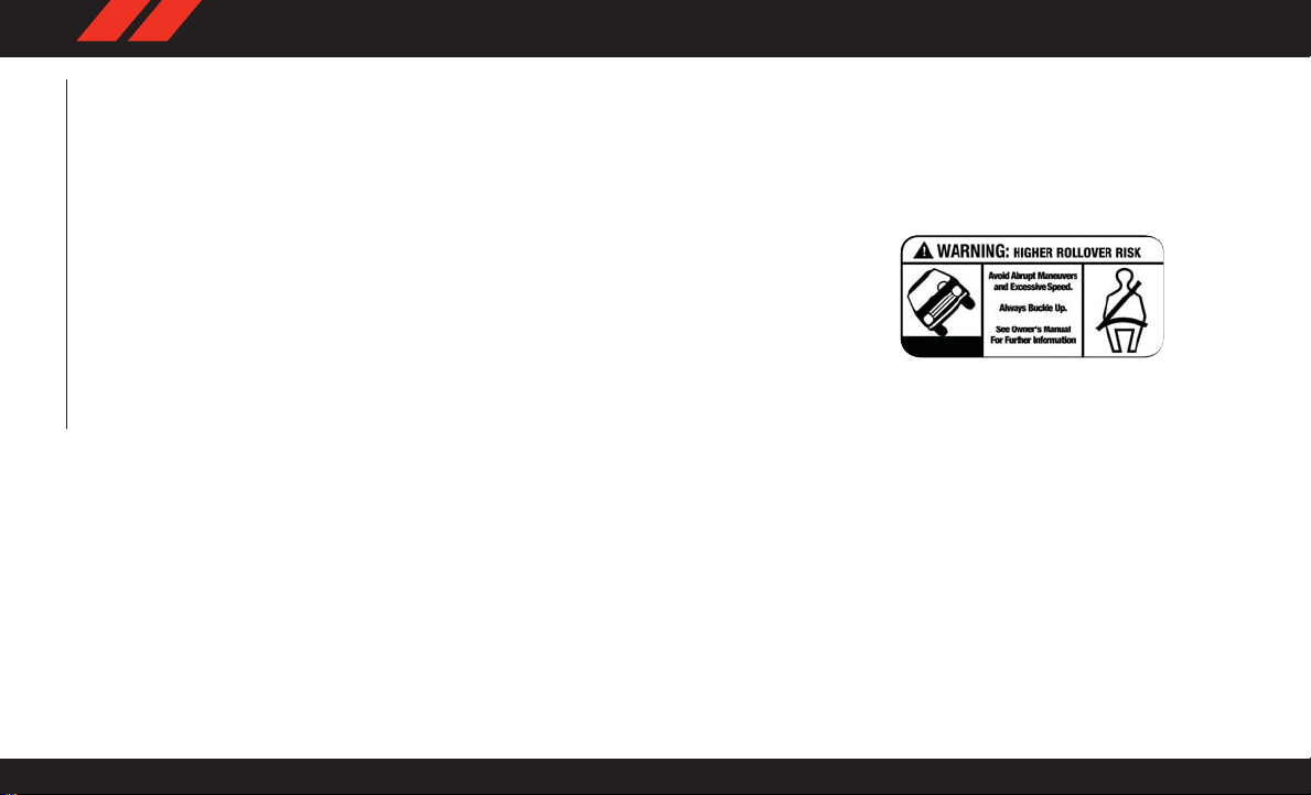
Instrument Panel
1 — Air Vents 4 — Instrument Cluster
2 — Paddle Shifter (–) 5 — Paddle Shifter (+)
3 — Steering Wheel 6 — Radio
8
Page 11
INTERIOR
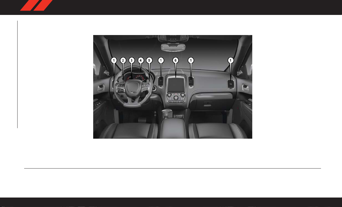
Instrument Panel
1 — Door Locks/Window Switches 4 — Climate Controls
2 — Seats 5 — Radio Controls
3 — Gear Selector 6 — Glove Compartment
9
Page 12

10
Page 13

GETTING TO KNOW YOUR VEHICLE
GETTINGTO KNOW YOUR VEHICLE
VEHICLE USER GUIDE — IF EQUIPPED .....13
KEYS .......................15
KeyFob.....................15
IGNITION SWITCH .................17
Keyless Push Button Ignition .........17
Dead Key Fob Battery .............18
REMOTE START — IF EQUIPPED .........18
T o Enter Remote Start Mode .........18
T o Exit Remote Start Mode Without Driving
The V ehicle ...................18
T o Exit Remote Start Mode And Drive The
Vehicle......................19
General Information ..............19
SENTRY KEY ...................19
Customer Key Programming .........20
Replacement Keys ...............20
General Information ..............20
VEHICLE SECURITY ALARM — IF EQUIPPED . .21
T o Arm The System ..............21
T o Disarm The System ............21
DOORS ......................22
Keyless Enter -N-Go — Passive Entry.....22
Automatic Unlock On Exit Feature — If
Equipped ....................26
Automatic Door Locks — If Equipped ....26
Child-Protection Door Lock System — Rear
Doors.......................26
SEATS.......................27
Driver Memory Seat — If Equipped .....27
Heated Seats ..................29
Front V entilated Seats .............31
60/40 Split Rear Seat .............32
Rear Captain's Chairs .............32
Folding Third Row ...............33
HEAD RESTRAINTS ................33
Supplemental Active Head Restraints — Front
Seats.......................34
Head Restraints — Rear Seats ........35
Head Restraint Removal — Rear Seats . . .36
Power Folding Third Row Head Restraints. .36
MIRRORS .....................37
Heated Mirrors — If Equipped ........37
EXTERIOR LIGHTS .................37
Headlight Switch ................37
Multifunction Lever ..............38
Daytime Running Lights — If Equipped . .38
High/Low Beam Switch ............38
Automatic High Beam — If Equipped . . .38
Automatic Headlights .............38
Headlights On Automatically With Wipers .39
Fog Lights — If Equipped ...........39
T urn Signals...................39
Lane Change Assist — If Equipped .....39
INTERIOR LIGHTS .................40
WINDSHIELD WIPERS AND WASHERS ......40
Windshield Wiper Operation..........40
Rain Sensing Wipers — If Equipped ....41
Rear W indow Wiper/Washer .........42
CLIMATE CONTROLS ...............42
Automatic Climate Control Overview .....42
Climate Control Functions ...........51
Automatic Temperature Control (ATC) — If
Equipped ....................52
11
Page 14

Operating Tips .................53
WINDOWS ....................56
Power W indows ................56
Wind Buffeting .................57
POWER SUNROOF — IF EQUIPPED .......58
Opening Sunroof ................58
Closing Sunroof.................58
Pinch Protect Feature .............59
Venting Sunroof — Express ..........59
GETTING TO KNOW YOUR VEHICLE
HOOD .......................59
Opening The Hood ...............59
Closing The Hood................60
LIFTGATE .....................60
Power Liftgate — If Equipped ........60
UNIVERSAL GARAGE DOOR OPENER
(HOMELINK) ....................61
Before You Begin Programming HomeLink .62
Erasing All The HomeLink Channels .....62
Identifying Whether You Have A Rolling Code
Or Non-Rolling Code Device..........62
Programming HomeLink To A Garage Door
Opener......................62
Programming HomeLink To A Miscellaneous
Device ......................64
Reprogramming A Single HomeLink
Button ......................64
General Information ..............64
INTERNAL EQUIPMENT ..............64
Electrical Power Outlets ...........64
Power Inverter — If Equipped ........67
12
Page 15

VEHICLE USER GUIDE — IF EQUIPPED
Access your Owner’s Information – right through
your Uconnect 4C or 4C NAV touchscreen radio
— If Equipped
T o access the Vehicle User Guide on your
Uconnect Touchscreen: Push the Uconnect
Apps button, then push the Vehicle User Guide
icon on your touchscreen. No Uconnect registration is required.
NOTE:
Vehicle User Guide features are not available
while the vehicle is moving. If you try to access
while the vehicle is in motion, the system will
display: Feature not available while the vehicle
is in motion.
Pre-Installed Features
• Your User Guide —
Updated in realtime
• Touchscreen convenience
• Maintenance
schedules and information
• Comprehensive
icon & symbol glossary
• Available when and
where you need it
• Customizable interface
•
Multilingual
13
Page 16
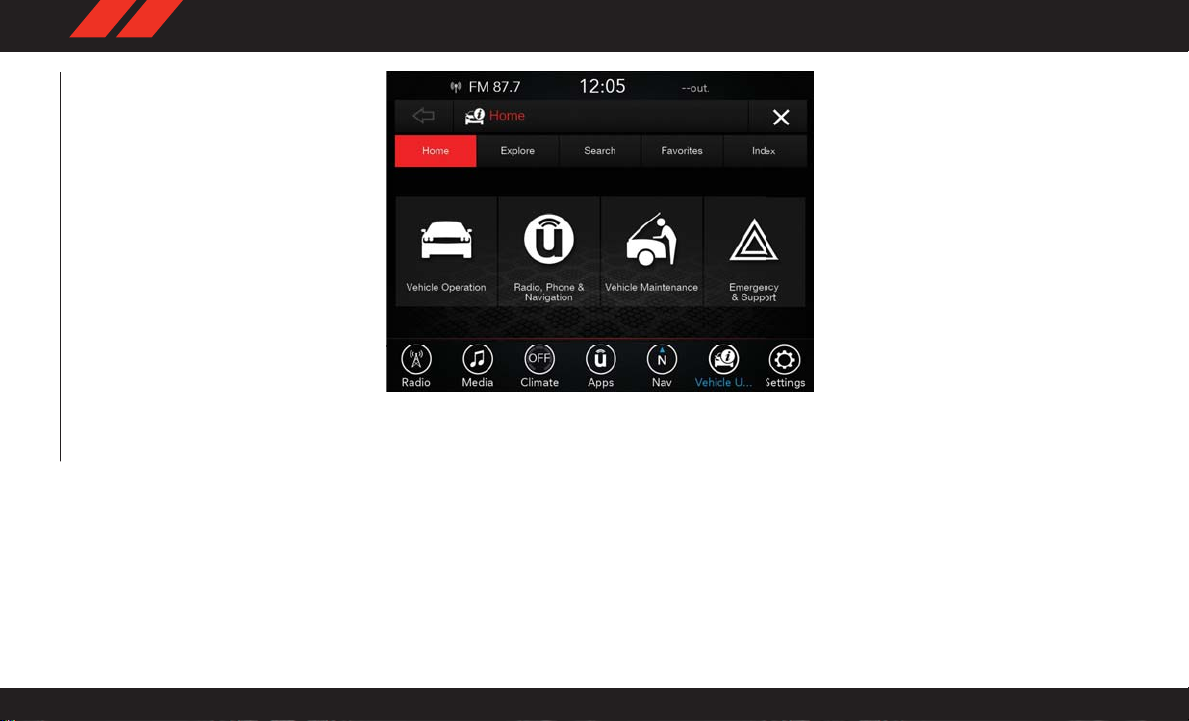
Vehicle User Guide Home Screen
NOTE:
GETTING TO KNOW YOUR VEHICLE
Uconnect screen images are for illustration purposes only and may not reflect exact software
for your vehicle.
14
Once you launch your Vehicle User Guide, you
will be able to explore your warranty information
and radio manual when and where you need
them. Y our Uconnect radio will display the Vehicle User Guide on your touchscreen radio to
assist in better understanding your vehicle.
There’s no app to download, no phone to connect and no external device needed for playback. Plus, it’s updated throughout the year, in
real-time, so it never goes out of date.
Page 17

Features/Benefits
• Pre-installed on your Uconnect touchscreen
radio
• Enhanced search and browsing capability
• Robust NAV application — If Equipped
• Add selected topics to a fast-access Favorites
category
• Icon and symbol glossary
• W arranty information
• Crucial driver information and assistance:
• Operating Instructions
• Warranty Information
• Fluid Level Standards
• Maintenance
Schedules
• Emergency Procedures
• 911 Contact and
More
Tip: When viewing a topic, tap the star icon to
add it to your Favorites, for easy access in the
future.
Enhanced Search And Browsing
Capability
Icon And Symbol Glossary
KEYS
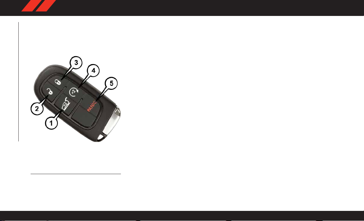
Key Fob
Your vehicle uses a keyless ignition system. The
ignition system consists of a key fob with Remote Keyless Entry (RKE) and a START/STOP
push button ignition system. The Remote Keyless Entry system consists of a key fob and
Keyless Enter -N-Go feature if equipped.
15
Page 18
NOTE:
The key fob may not be found if it is located next
to a mobile phone, laptop or other electronic
device; these devices may block the key fob’s
wireless signal.
GETTING TO KNOW YOUR VEHICLE
Key Fob
1 — Liftgate 4 — Remote Start
2 — Unlock 5 — Panic
3 — Lock
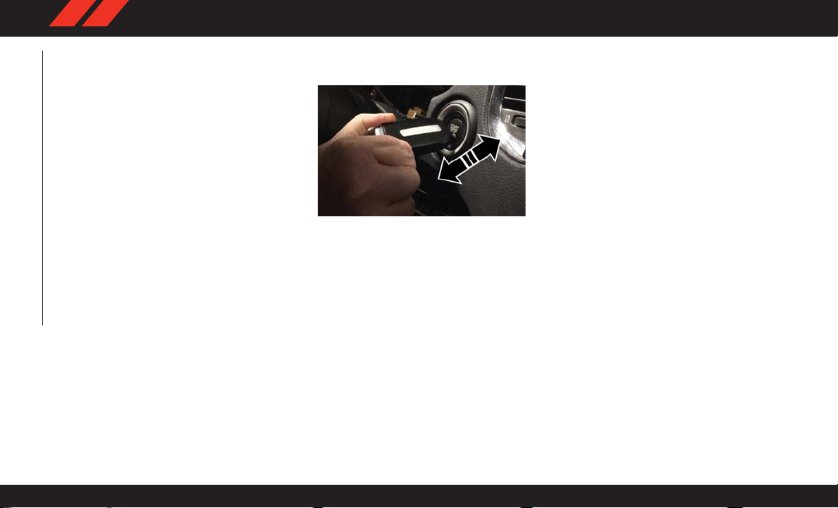
NOTE:
In case the ignition switch does not change with
the push of a button, the key fob may have a low
or dead battery. In this situation, a back up
method can be used to operate the ignition
switch. Put the nose side of the key fob (side
opposite of the Emergency Key) against the
ENGINE STAR T/STOP button and push to operate the ignition switch.
To Unlock The Doors And Liftgate
Push and release the unlock button on the key
fob once to unlock the driver's door or twice
within five seconds to unlock all doors and the
liftgate.
All doors can be programmed to unlock on the
first push of the unlock button. Refer to
“Uconnect Settings” in “Multimedia” in the
Owner’s Manual at
www.mopar.com/en-us/care/owner-manual.html
(U.S. Residents) or www.owners.mopar.ca (Canadian Residents) for further information.
To Lock The Doors And Liftgate
Push and release the lock button on the key fob
to lock all doors and liftgate.
Vehicles Equipped With Keyless Enter-N-Go —
Passive Entry
If one or more doors are open, or the liftgate is
open, the doors will lock. The doors will unlock
again automatically if the key is left inside the
passenger compartment, otherwise the doors
will stay locked.
General Information
The following regulatory statement applies to all
radio frequency (RF) devices equipped in this
vehicle:
This device complies with Part 15 of the FCC
Rules and with Industry Canada license-exempt
RSS standard(s). Operation is subject to the
following two conditions:
1. This device may not cause harmful interference, and
16
Page 19
2. This device must accept any interference
received, including interference that may
cause undesired operation.
NOTE:
Changes or modifications not expressly approved by the party responsible for compliance
could void the user’s authority to operate the
equipment.
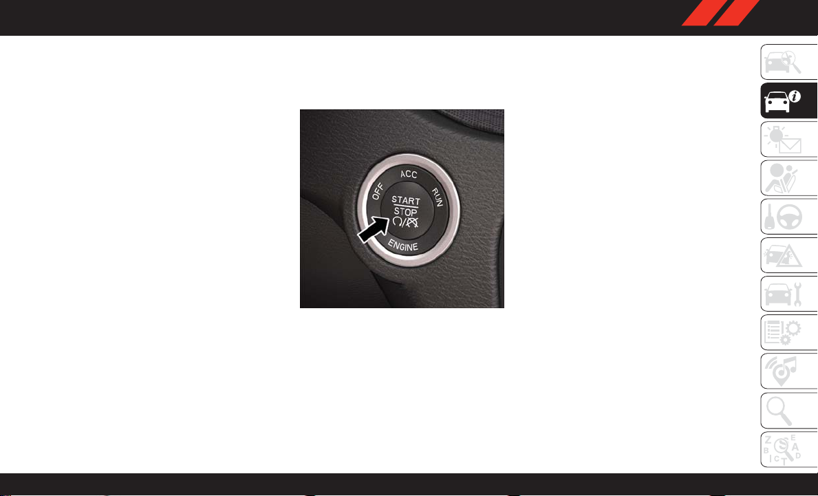
IGNITION SWITCH
Keyless Push Button Ignition
This feature allows the driver to operate the
ignition with the push of a button, as long as the
key fob is in the passenger compartment.
The Keyless Push Button Ignition has three
operating modes which are labeled and will
illuminate when in position. The three modes
are OFF, ACC, and ON/RUN.
Keyless Push Button Ignition
NOTE:
In case the ignition switch does not change with
the push of a button, the key fob may have a low
or dead battery. In this situation, a back up
method can be used to operate the ignition
switch. Put the nose side of the key fob (side
opposite of the Emergency Key) against the
ENGINE START/STOP button and push to operate the ignition switch.
17
Page 20
Dead Key Fob Battery
Key Not Detected Feature
If the ignition position does not change with a
push of the ignition button, and the instrument
cluster display message “Key Fob Not Detected” is being displayed, the key fob may have
a low or dead battery . In this situation, a back up
method can be used to operate the keyless push
button ignition. Put the nose side (side opposite
of the emergency key) of the key fob against the
keyless ignition push button and push to operate the ignition. Once the starter engages and
the engine starts remove the key fob from the
keyless ignition push button.
GETTING TO KNOW YOUR VEHICLE
18
Low Or Dead Key Fob Battery Starting
Procedure
REMOTE START — IF EQUIPPED
To Enter Remote Start Mode
Push and release the remote start button on the
key fob twice within five seconds. The vehicle
doors will lock, the parking lights will flash, and
the horn will chirp twice (if programmed). Then,
the engine will start, and the vehicle will remain
in the Remote Start mode for a 15-minute
cycle.
NOTE:
• If an engine fault is present or fuel level is low,
the vehicle will start and then shut down in
10 seconds.
• The park lamps will turn on and remain on
during Remote Start mode.
• For security, power window and power sunroof
operation (if equipped) are disabled when the
vehicle is in the Remote Start mode.
• The engine can be started two consecutive
times with the key fob. However, the ignition
must be cycled by pushing the START/STOP
button twice (or the ignition switch must be
cycled to the ON/RUN position) before you
can repeat the start sequence for a third cycle.
To Exit Remote Start Mode Without Driving
The Vehicle
Push and release the remote start button one
time or allow the engine to run for the entire
15-minute cycle.
Page 21

NOTE:
T o avoid unintentional shutdowns, the system
will disable with a one time push of the remote
start button for two seconds after receiving a
valid remote start request.
To Exit Remote Start Mode And Drive The
Vehicle
Before the end of 15-minute cycle, push and
release the unlock button on the key fob to
unlock the doors, or unlock the vehicle using
Keyless Enter-N-Go — Passive Entry via the
door handles, and disarm the vehicle security
alarm (if equipped). Then, prior to the end of the
15-minute cycle, push and release the STAR T/
STOP button.
NOTE:
For vehicles equipped with the Keyless EnterN-Go — Passive Entry feature, the message
“Remote Start Active — Push Start Button” will
display in the instrument cluster display until
you push the ignition START button.
General Information
The following regulatory statement applies to all
radio frequency (RF) devices equipped in this
vehicle:
This device complies with Part 15 of the FCC
Rules and with Industry Canada license-exempt
RSS standard(s). Operation is subject to the
following two conditions:
1. This device may not cause harmful interference, and
2. This device must accept any interference
received, including interference that may
cause undesired operation.
NOTE:
Changes or modifications not expressly approved by the party responsible for compliance
could void the user’s authority to operate the
equipment.
SENTRY KEY
The Sentry Key Immobilizer system prevents
unauthorized vehicle operation by disabling the
engine. The system does not need to be armed
or activated. Operation is automatic, regardless
of whether the vehicle is locked or unlocked.
The system uses a key fob and a Keyless Push
Button Ignition, and a RF receiver to prevent
unauthorized vehicle operation. Therefore, only
key fobs that are programmed to the vehicle can
be used to start and operate the vehicle. If an
invalid key fob is used to attempt to start and
operate the vehicle, the system will not allow the
engine to crank. If an invalid key fob is used to
start the engine, the system will shut the engine
off in two seconds.
After placing the ignition to the ON/RUN mode,
the vehicle security light will turn on for three
seconds for a bulb check. If the light remains on
after the bulb check, it indicates that there is a
problem with the electronics. In addition, if the
light begins to flash after the bulb check, it
indicates that someone used an invalid key fob
to start the engine. Either of these conditions
will result in the engine being shut off after two
seconds.
19
Page 22
If the vehicle security light turns on during
normal vehicle operation (vehicle running for
longer than 10 seconds), it indicates that there
is a fault in the electronics. Should this occur,
have the vehicle serviced as soon as possible by
an authorized dealer.
CAUTION!
The Sentry Key Immobilizer system is not
compatible with some aftermarket remote
starting systems. Use of these systems may
result in vehicle starting problems and loss of
security protection.
All of the key fobs provided with your new
vehicle have been programmed to the vehicle
electronics.
GETTING TO KNOW YOUR VEHICLE
Customer Key Programming
Programming key fobs may be performed at an
authorized dealer.
20
Replacement Keys
NOTE:
Only key fobs that are programmed to the vehicle electronics can be used to start and operate the vehicle. Once a key fob is programmed
to a vehicle, it cannot be programmed to any
other vehicle.
CAUTION!
• Always remove the key fobs from the vehicle and lock all doors when leaving the
vehicle unattended.
• For vehicles equipped with Keyless EnterN-Go — Ignition, always remember to
place the ignition in the OFF position.
NOTE:
Duplication of key fobs may be performed at an
authorized dealer. This procedure consists of
programming a blank key fob to the vehicle
electronics. A blank key fob is one that has
never been programmed.
When having the Sentry Key Immobilizer System serviced, bring all vehicle keys with you to
an authorized dealer.
General Information
The following regulatory statement applies to all
radio frequency (RF) devices equipped in this
vehicle:
This device complies with Part 15 of the FCC
Rules and with Industry Canada license-exempt
RSS standard(s). Operation is subject to the
following two conditions:
1. This device may not cause harmful interference, and
2. This device must accept any interference
received, including interference that may
cause undesired operation.
NOTE:
Changes or modifications not expressly approved by the party responsible for compliance
could void the user’s authority to operate the
equipment.
Page 23

VEHICLE SECURITY ALARM — IF EQUIPPED
The vehicle security alarm monitors the vehicle
doors for unauthorized entry and the Keyless
Enter-N-Go — Ignition for unauthorized operation. While the vehicle security alarm is armed,
interior switches for door locks and liftgate release are disabled. If something triggers the
alarm, the vehicle security alarm will provide
the following audible and visible signals: the
horn will pulse, the park lamps and/or turn
signals will flash, and the vehicle security light
in the instrument cluster will flash.
To Arm The System
Follow these steps to arm the vehicle security
alarm:
1. Make sure the vehicle’ s ignition is placed in
the OFF mode (refer to "Ignition Switch" in
this chapter for further information).
2. Perform one of the following methods to lock
the vehicle:
• Push lock on the interior power door lock
switch with the driver and/or passenger
door open.
• Push the lock button on the exterior Passive Entry Door Handle with a valid key fob
available in the same exterior zone (refer
to "Keyless Enter-N-Go — Passive Entry,"
located in “Doors” in “Getting T o Know
Your Vehicle" for further information).
• Push the lock button on the key fob.
3. If any doors are open, close them.
NOTE:
Security System Manual Override
The vehicle security alarm will not arm if you
lock the doors using the manual door lock
plunger.
To Disarm The System
The vehicle security alarm can be disarmed
using any of the following methods:
• Push the unlock button on the key fob.
• Grasp the passive entry unlock door handle (if
equipped, refer to "Keyless Enter-N-Go —
Passive Entry" located in “Doors” in “Getting
T o Know Your Vehicle" for further information).
• Cycle the vehicle ignition system out of the
OFF position.
– For vehicles equipped with Keyless
Enter-N-Go — Passive Entry, push the
keyless ignition button (requires at least
one valid key fob in the vehicle).
– For vehicles not equipped with Keyless
Enter-N-Go — Passive Entry, insert a
valid key into the ignition and turn the key
to the ON position.
NOTE:
• The driver's door key cylinder and the liftgate
button on the key fob cannot arm or disarm
the vehicle security alarm.
• The vehicle security alarm remains armed
during power liftgate entry. Pushing the liftgate button will not disarm the vehicle security alarm. If someone enters the vehicle
through the liftgate and opens any door, the
alarm will sound.
21
Page 24

• When the vehicle security alarm is armed, the
interior power door lock switches will not unlock the doors.
The vehicle security alarm is designed to protect
your vehicle. However, you can create conditions where the system will give you a false
alarm. If one of the previously described arming
sequences has occurred, the vehicle security
alarm will arm regardless of whether you are in
the vehicle or not. If you remain in the vehicle
and open a door, the alarm will sound. If this
occurs, disarm the vehicle security alarm.
If the vehicle security alarm is armed and the
battery becomes disconnected, the vehicle security alarm will remain armed when the battery
is reconnected; the exterior lights will flash, and
the horn will sound. If this occurs, disarm the
vehicle security alarm.
GETTING TO KNOW YOUR VEHICLE
DOORS
Keyless Enter-N-Go — Passive Entry
The Passive Entry system is an enhancement to
the vehicle’s Remote Keyless Entry system and
a feature of Keyless Enter-N-Go — Passive Entry. This feature allows you to lock and unlock
the vehicle’s door(s) without having to push the
key fob lock or unlock buttons.
NOTE:
• Passive Entry may be programmed ON/OFF.
Refer to “Uconnect Settings” in “Multimedia” in the Owner’s Manual at
www.mopar.com/en-us/care/owner-manual.html
(U.S. Residents) or www.owners.mopar.ca
(Canadian Residents) for further information.
• If wearing gloves on your hands, or if it has
been raining/snowing on the Passive Entry
door handle, the unlock sensitivity can be
affected, resulting in a slower response time.
• If the vehicle is unlocked by Passive Entry and
no door is opened within 60 seconds, the
vehicle will re-lock and if equipped will arm
the security alarm.
• The key fob may not be able to be detected by
the vehicle passive entry system if it is located
next to a mobile phone, laptop or other electronic device; these devices may block the key
fob's wireless signal and prevent the passive
entry handle from locking/unlocking the vehicle.
• Passive Entry activates illuminated approach
for the time set by the customer (0, 30, 60, or
90 seconds), and flashes the turn signal
lights. Refer to “Uconnect Settings” in “Multimedia” in the Owner’s Manual at
ww.mopar.com/en-us/care/owner-manual.html
(U.S. Residents) or www.owners.mopar.ca
(Canadian Residents) for further information.
22
Page 25
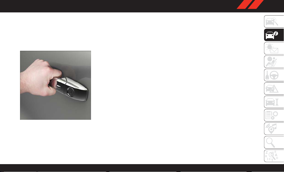
To Unlock From The Driver's Side:
With a valid Passive Entry key fob within 5 ft
(1.5 m) of the driver's door handle, grab the
driver's front door handle to unlock the driver's
door automatically. The interior door panel lock
knob will raise when the door is unlocked.
Grab The Door Handle To Unlock
NOTE:
If “Unlock All Doors 1st Press” is programmed,
all doors will unlock when you grab hold of the
driver’s front door handle. T o select between
“Unlock Driver Door 1st Press” and “Unlock All
Doors 1st Press”, refer to “Uconnect Settings”
in “Multimedia” in the Owner’s Manual at
www.mopar.com/en-us/care/owner-manual.html
(U.S. Residents) or www.owners.mopar.ca (Canadian Residents) for further information.
To Unlock From The Passenger Side:
With a valid Passive Entry key fob within 5 ft
(1.5 m) of the passenger door handle, grab the
front passenger door handle to unlock all four
doors automatically. The interior door panel lock
knob will raise when the door is unlocked.
NOTE:
All doors will unlock when the front passenger
door handle is grabbed regardless of the driver’s
door unlock preference setting (“Unlock Driver
Door 1st Press” or “Unlock All Doors 1st
Press”).
Preventing Inadvertent Locking Of Passive Entry
Key Fob In Vehicle
T o minimize the possibility of unintentionally
locking a Passive Entry key fob inside your
vehicle, the Passive Entry system is equipped
with an automatic door unlock feature, which
will function if the ignition is OFF.
If one of the vehicle doors is open, and the door
panel switch is used to lock the vehicle, once all
open doors have been closed, the vehicle
checks the inside and outside of the vehicle for
any valid Passive Entry key fob. If one of the
vehicle's Passive Entry key fob is detected inside the vehicle, and no other valid Passive
Entry key fob are detected outside the vehicle,
the Passive Entry System automatically unlocks
all vehicle doors and chirps the horn three times
(on the third attempt, ALL doors will lock, and
the Passive Entry key fob can be locked in the
vehicle).
23
Page 26
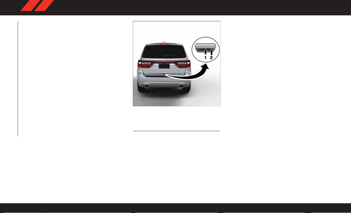
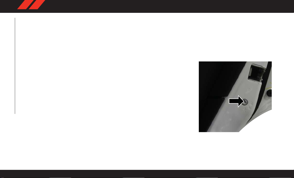
To Unlock/Enter The Liftgate
The liftgate passive entry unlock feature is built
into the electronic liftgate handle. With a valid
Passive Entry key fob within 5 ft (1.5 m) of the
liftgate, pull the electronic liftgate handle for a
power open on vehicles equipped with Power
Liftgate. Pull the electronic liftgate handle and
lift for Manual Liftgate vehicles.
NOTE:
If the vehicle is unlocked, the liftgate will open
with the handle and no key fob is required.
GETTING TO KNOW YOUR VEHICLE
Electronic Liftgate Handle
1 — Electronic Release Switch
2 — Lock Button Location
To Lock The Liftgate
With a valid Passive Entry key fob within 5 ft
(1.5 m) of the liftgate, push the passive entry
lock button located to the right of electronic
liftgate handle.
NOTE:
If “Unlock All Doors 1st Press” is programmed
in Uconnect Settings, all doors will unlock when
you push the button on the liftgate. If "Unlock
Driver Door 1st Press" is programmed in
Uconnect Settings, the liftgate will unlock when
you push the button on the liftgate. For further
information, refer to “Uconnect Settings” in
“Multimedia” in the Owner’s Manual at
www.mopar.com/en-us/care/owner-manual.html
(U.S. Residents) or www.owners.mopar.ca (Canadian Residents) for further information.
24
Page 27
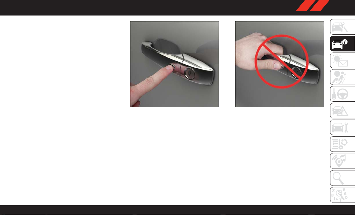
To Lock The Vehicle’s Doors
With one of the vehicle’s Passive Entry key fob
within 5 ft (1.5 m) of the driver or passenger
front door handle, push the door handle lock
button to lock all four doors and liftgate.
NOTE:
This feature will cause the horn to chirp when the
doors are locked with the door handle lock button.
This feature can be turned on or off. To change the
current setting, refer to “Uconnect Settings” in
“Multimedia” in the Owner’ s Manual at
www.mopar.com/en-us/care/owner-manual.html
(U.S. Residents) or www.owners.mopar.ca (Canadian Residents) for further information.
Push The Door Handle Button To Lock Do NOT Grab Handle When Locking
NOTE:
Do NOT grab the door handle, when pushing the
door handle button. This could unlock the
door(s).
NOTE:
• After pushing the door handle button, you
must wait two seconds before you can lock or
unlock the doors, using either Passive Entry
door handle or door handle button. This is
done to allow you to check if the vehicle is
locked by pulling the door handle, without the
vehicle reacting and unlocking.
• The Passive Entry system will not operate if
the key fob battery is dead.
25
Page 28
• Closeness to mobile devices can have an effect on the passive entry system.
The vehicle doors can also be locked by using
the key fob lock button or the lock button
located on the vehicle’ s interior door panel.
General Information
The following regulatory statement applies to all
radio frequency (RF) devices equipped in this
vehicle:
This device complies with Part 15 of the FCC
Rules and with Industry Canada license-exempt
RSS standard(s). Operation is subject to the
following two conditions:
1. This device may not cause harmful interfer-
ence, and
GETTING TO KNOW YOUR VEHICLE
2. This device must accept any interference
received, including interference that may
cause undesired operation.
NOTE:
Changes or modifications not expressly approved by the party responsible for compliance
could void the user’s authority to operate the
equipment.
Automatic Unlock On Exit Feature — If
Equipped
If Auto Unlock is enabled, this feature will
unlock all the doors when any door is opened if
the vehicle is stopped and in PARK. Refer to
“Uconnect Settings” in “Multimedia” for further information.
Automatic Door Locks — If Equipped
When enabled, the door locks will lock automatically when the vehicle’s speed exceeds
15 MPH (24 km/h). Auto door lock feature is
enabled/disabled in the Uconnect Settings sections in the radio. Refer to “Uconnect Settings”
in “Multimedia” in the Owner’s Manual at
www.mopar.com/en-us/care/owner-manual.html
(U.S. Residents) or www.owners.mopar.ca (Canadian Residents) for further information.
Child-Protection Door Lock System —
Rear Doors
T o provide a safer environment for small children riding in the rear seats, the rear doors are
equipped with Child-Protection Door Lock system.
To Engage Or Disengage The Child Protection
Door Lock System
1. Open the rear door.
2. Insert the tip of the emergency key into the
lock and rotate to the lock or unlock position.
3. Repeat steps 1 and 2 for the opposite rear
door.
Child-Protection Door Lock Function
26
Page 29
WARNING!
Avoid trapping anyone in a vehicle in a collision. Remember that the rear doors can only
be opened from the outside with the ChildProtection locks are engaged (locked).
NOTE:
For emergency exit with the system engaged,
move the lock knob up (unlocked position), roll
down the window, and open the door with the
outside door handle.
SEATS
Seats are a part of the Occupant Restraint
System of the vehicle.
WARNING!
• It is dangerous to ride in a cargo area,
inside or outside of a vehicle. In a collision,
people riding in these areas are more likely
to be seriously injured or killed.
• Do not allow people to ride in any area of
your vehicle that is not equipped with seats
and seat belts. In a collision, people riding
WARNING!
in these areas are more likely to be seriously injured or killed.
• Be sure everyone in your vehicle is in a seat
and using a seat belt properly .
Driver Memory Seat — If Equipped
This feature allows the driver to store up to two
different memory profiles for easy recall through
a memory switch. Each memory profile contains
desired position settings for the driver seat, side
mirrors, and power tilt and telescopic steering
column (if equipped) and a set of desired radio
station presets. Your key fob can also be programmed to recall the same positions when the
unlock button is pushed.
NOTE:
Your vehicle is equipped with two key fobs, one
key fob can be linked to memory position 1 and
the other key fob can be linked to memory
position 2.
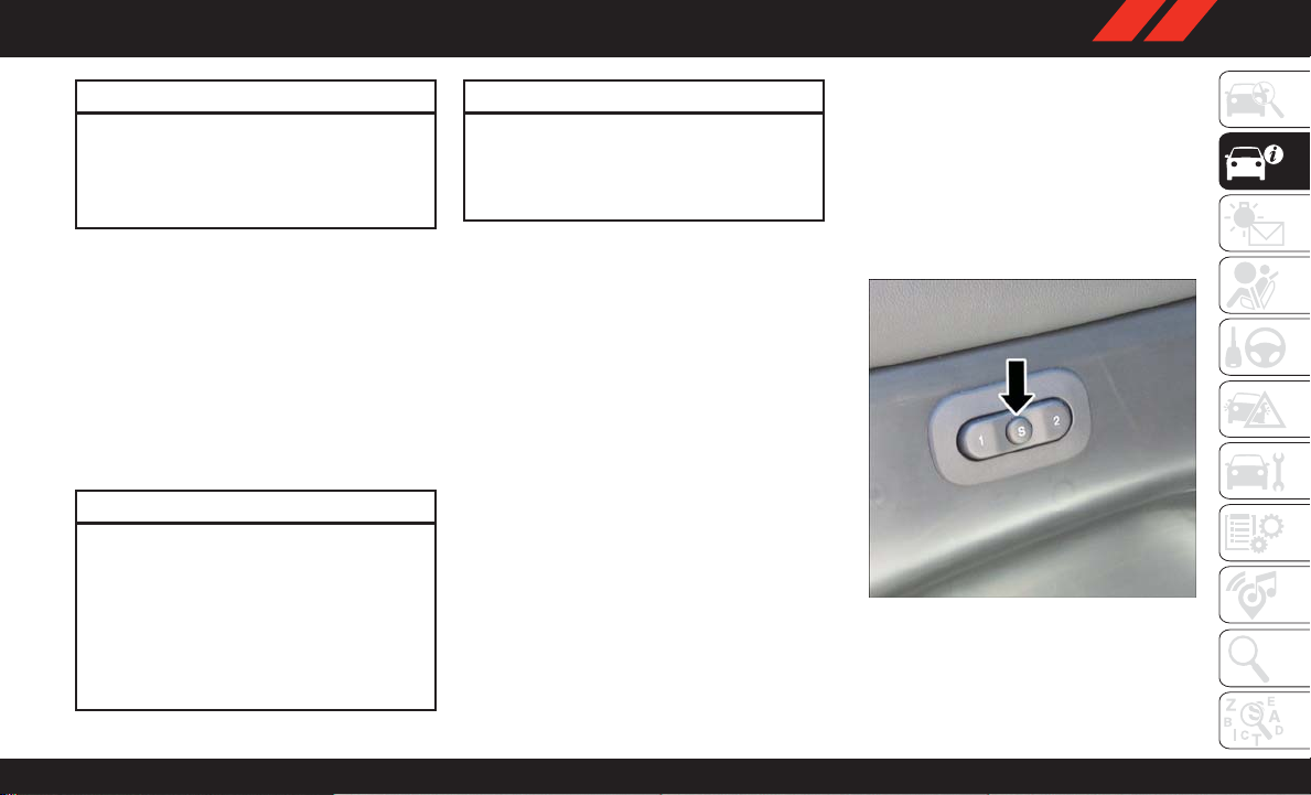
The memory seat switch is located on the driver’s door trim panel. The switch consists of three
buttons:
• The set (S) button, which is used to activate
the memory save function.
• The (1) and (2) buttons which are used to
recall either of two pre-programmed memory
profiles.
Memory Seat Buttons
27
Page 30

Programming The Memory Feature
NOTE:
T o create a new memory profile, perform the
following:
1. Cycle the vehicle’s ignition to the ON/RUN
position (Do not start the engine).
2. Adjust all memory profile settings to desired
preferences (i.e., seat, side mirror, power tilt
and telescopic steering column [if
equipped], and radio station presets).
3. Push and release the set (S) button on the
memory switch.
4. Within five seconds, push and release either
of the memory buttons (1) or (2). The instrument cluster display will display which
memory position has been set.
GETTING TO KNOW YOUR VEHICLE
NOTE:
• Memory profiles can be set without the ve-
hicle in PARK, but the vehicle must be in
PARK to recall a memory profile.
• To set a memory profile to your key fob, refer to
“Linking And Unlinking The Remote Keyless
Entry Key Fob To Memory” in this section.
28
Linking And Unlinking The Remote Keyless
Entry Key Fob To Memory
Your key fobs can be programmed to recall one
of two pre-programmed memory profiles by
pushing the unlock button on the key fob.
NOTE:
Before programming your key fobs you must
select the “Memory Linked T o FOB” feature
through the Uconnect system screen. Refer to
“Uconnect Settings” in “Multimedia” in the
Owner’s Manual at
www.mopar.com/en-us/care/owner-manual.html
(U.S. Residents) or www.owners.mopar.ca (Canadian Residents) for further information.
T o program your key fobs, perform the following:
1. Cycle the vehicle’s ignition to the OFF
position.
2. Select a desired memory profile, 1 or 2.
NOTE:
If a memory profile has not already been set,
refer to "Programming The Memory Feature"
in this section for instructions on how to set
a memory profile.
3. Once the profile has been recalled, push and
release the set (S) button on the memory
switch.
4. Within five seconds, push and release button (1) or (2) accordingly. “Memory Profile
Set” (1 or 2) will display in the instrument
cluster.
5. Push and release the lock button on the key
fob within 10 seconds.
NOTE:
Your key fobs can be unlinked to your memory
settings by pushing the set (S) button, and
within 10 seconds, followed by pushing the
unlock button on the key fob.
Memory Position Recall
NOTE:
The vehicle must be in PARK to recall memory
positions. If a recall is attempted when the
vehicle is not in P ARK, a message will be displayed in the instrument cluster display .
Driver One Memory Position Recall
• To recall the memory settings for driver one
using the memory switch, push memory button (1) on the memory switch.
Page 31

• To recall the memory settings for driver one
using the key fob, push the unlock button on
the key fob linked to memory position 1.
Driver Two Memory Position Recall
• To recall the memory setting for driver two
using the memory switch, push memory button (2) on the memory switch.
• To recall the memory settings for driver two
using the key fob, push the unlock button on
the key fob linked to memory position 2.
A recall can be canceled by pushing any of the
memory buttons during a recall (S, 1, or 2), or
by pushing any of the seat adjustment switches.
When a recall is canceled, the driver's seat and
steering column (if equipped) stop moving. A
delay of one second will occur before another
recall can be selected.
Easy Entry/Exit Seat
This feature provides automatic driver seat positioning to enhance driver mobility when entering and exiting the vehicle.
The distance the driver seat moves depends on
where you have the driver seat positioned when
you cycle the vehicle’s ignition to the OFF position.
• When you cycle the vehicle’s ignition to the
OFF position, the driver seat will move about
2.4 inches (60 mm) rearward if the driver seat
position is greater than or equal to 2.7 inches
(67.7 mm) forward of the rear stop. The seat
will return to its previously set position when
you cycle the vehicle’s ignition to the ACC or
RUN position.
• The Easy Entry/Easy Exit feature is disabled
when the driver seat position is less than
0.9 of an inch (22.7 mm) forward of the rear
stop. At this position, there is no benefit to the
driver by moving the seat for Easy Exit or Easy
Entry.
Each stored memory setting will have an associated Easy Entry and Easy Exit position.
NOTE:
The Easy Entry/Exit feature is not enabled when
the vehicle is delivered from the factory . The Easy
Entry/Exit feature is enabled (or later disabled)
through the programmable features in the
Uconnect system. Refer to “Uconnect Settings”
in “Multimedia” in your Owner’s Manual at
www.mopar.com/en-us/care/owner-manual.html
(U.S. Residents) or www.owners.mopar.ca (Canadian Residents) for further details.
Heated Seats
On some models, the front and rear seats may
be equipped with heaters located in the seat
cushions and seat backs.
WARNING!
• Persons who are unable to feel pain to the
skin because of advanced age, chronic
illness, diabetes, spinal cord injury, medication, alcohol use, exhaustion or other
physical condition must exercise care
when using the seat heater. It may cause
burns even at low temperatures, especially
if used for long periods of time
29
Page 32

WARNING!
• Do not place anything on the seat or seatback that insulates against heat, such as a
blanket or cushion. This may cause the
seat heater to overheat. Sitting in a seat
that has been overheated could cause serious burns due to the increased surface
temperature of the seat.
Front Heated Seats
The front heated seats control buttons are located within the climate or controls screen of
the touchscreen.
You can choose from HI, LO, or OFF heat settings. The indicator arrows in touchscreen buttons indicate the level of heat in use. Two
GETTING TO KNOW YOUR VEHICLE
indicator arrows will illuminate for HI, one for
LO and none for OFF .
• Press the heated seat button
the HI setting on.
• Press the heated seat button
time to turn the LO setting on.
• Press the heated seat button
to turn the heating elements off.
30
once to turn
a third time
a second
If the HI-level setting is selected, the system
will automatically switch to LO-level after approximately 60 minutes of continuous operation. At that time, the display will change from
HI to LO, indicating the change. The LO-level
setting will turn off automatically after approximately 45 minutes.
NOTE:
• Once a heat setting is selected, heat will be
felt within two to five minutes.
• The engine must be running for the heated
seats to operate.
Vehicles Equipped With Remote Start
On models that are equipped with remote start,
the heated seats can be programmed to come
on during a remote start.
This feature can be programmed through the
Uconnect system. Refer to “Uconnect Settings” in
“Multimedia” in your Owner’s Manual at
www.mopar.com/en-us/care/owner-manual.html
(U.S. Residents) or www.owners.mopar.ca (Canadian Residents) for further details.
WARNING!
• Persons who are unable to feel pain to the
skin because of advanced age, chronic
illness, diabetes, spinal cord injury, medication, alcohol use, exhaustion or other
physical condition must exercise care
when using the seat heater . It may cause
burns even at low temperatures, especially
if used for long periods of time
• Do not place anything on the seat or seatback that insulates against heat, such as a
blanket or cushion. This may cause the
seat heater to overheat. Sitting in a seat
that has been overheated could cause serious burns due to the increased surface
temperature of the seat.
Rear Heated Seats — If Equipped
On some models, the two rear outboard seats
may be equipped with heated seats. There are
two heated seat switches that allow the rear
passengers to operate the seats independently.
The heated seat switches for each heater are
located on the rear of the center console.
Page 33

You can choose from HI, LO, or OFF heat settings. Amber indicator lights in each switch
indicate the level of heat in use. T wo indicator
lights will illuminate for HI, one for LO and none
for OFF.
Push the switch once to select HIlevel heating. Push the switch a second time to select LO-level heating.
Push the switch a third time to shut
the heating elements off.
When the HI-level setting is selected, the heater
will provide a boosted heat level during the first
four minutes of operation. Then, the heat output
will drop to the normal HI-level. If the HI-level
setting is selected, the system will automatically switch to LO-level after approximately
60 minutes of continuous operation. At that
time, the number of indicator lights changes
from two to one, indicating the change. The
LO-level setting will turn off automatically after
approximately 45 minutes.
WARNING!
• Persons who are unable to feel pain to the
skin because of advanced age, chronic
WARNING!
illness, diabetes, spinal cord injury, medication, alcohol use, exhaustion or other
physical condition must exercise care
when using the seat heater. It may cause
burns even at low temperatures, especially
if used for long periods of time
• Do not place anything on the seat or seatback that insulates against heat, such as a
blanket or cushion. This may cause the
seat heater to overheat. Sitting in a seat
that has been overheated could cause serious burns due to the increased surface
temperature of the seat.
Front Ventilated Seats
If your vehicle is equipped with ventilated seats,
the seat cushion and seat back will have fans
that draw the air from the passenger compartment and move air through fine perforations in
the seat cover to help keep the driver and front
passenger cooler in higher ambient temperatures. The fans operate at two speeds, HI and
LO.
The front ventilated seats control buttons are
located within the Uconnect system. You can
gain access to the control buttons through the
climate screen or the controls screen.
• Press the ventilated seat button
choose HI.
• Press the ventilated seat button
time to choose LO.
• Press the ventilated seat button
time to turn the ventilated seat off.
NOTE:
The engine must be running for the ventilated
seats to operate.
Vehicles Equipped With Remote Start
On models that are equipped with remote start,
the ventilated seats can be programmed to
come on during a remote start.
This feature can be programmed through the
Uconnect system. Refer to “Uconnect Settings”
in “Mulitmedia” in the Owner's Manual at
www.mopar.com/en-us/care/owner-manual.html
(U.S. Residents) or www.owners.mopar.ca (Canadian Residents) for further information.
once to
a second
a third
31
Page 34

60/40 Split Rear Seat
The left or right side of the second row seatback
can be folded flat to carry cargo. The left and
right side of the second row seat can also be
tumbled forward to allow access to the third row
seat.
GETTING TO KNOW YOUR VEHICLE
Seat Release Lever
Fold And Tumble
Pull upward on the release lever to release the
seat.
NOTE:
Also, pulling upward on this handle allows the
outboard seating positions to be reclined.
T umble the seat forward using the red pull strap
located behind the seatback.
Tumble Pull Strap
NOTE:
If sitting in the third row seat, pull rearward on
the tumble pull strap located at the rear of the
seat and tumble the seat forward.
Rear Captain's Chairs
Fold And Tumble
Rear Captain's Chairs
The left or right side of the second row seatback
can be folded flat to carry cargo. When the lower
storage compartment is accessed using the rear
push button it allows the armrest to flip forward
for “fold flat mode.”
Fold flat mode allows the console armrest to be
lowered below fold flat seat plane and protect
the armrest vinyl from damage when using the
vehicle to haul cargo.
32
Page 35

The left and right side of the second row seat
can also be tumbled forward to allow access to
the third row seat. Pull upward on the release
lever to release the seat. Pulling upward on this
handle allows the outboard seating positions to
be reclined.
T umble the seat forward using the red pull strap
located behind the seatback.
NOTE:
If sitting in the third row seat, pull rearward on
the tumble pull strap located at the rear of the
seat and tumble the seat forward.
Stepping Pad Location
If your vehicle is equipped with a mini console
there is a stepping pad to allow passengers to
easily access the third row seats.
Folding Third Row
Both third row seats can be folded forward to
increase the cargo area. To lower either seat,
pull on the release handle located on back of the
seat and lower the seat using the pull strap
located next to the release handle.
NOTE:
The second row seats must be in their full
upright position or tumbled when folding the
third row seats.
T o raise the seat, pull the seat toward you using
the strap located on the back of the seat.
NOTE:
You may experience deformation in the seat
cushion from the seat belt buckles if the seats
are left folded for an extended period of time.
This is normal and by simply opening the seats
to the open position, over time the seat cushion
will return to its normal shape.
WARNING!
Be certain that the seatback is securely
locked into position. If the seatback is not
securely locked into position the seat will not
provide the proper stability for child seats
and/or passengers. An improperly latched
seat could cause serious injury.
HEAD RESTRAINTS
Head restraints are designed to reduce the risk
of injury by restricting head movement in the
event of a rear impact. Head restraints should
be adjusted so that the top of the head restraint
is located above the top of your ear.
WARNING!
• All occupants, including the driver, should
not operate a vehicle or sit in a vehicle’s
seat until the head restraints are placed in
their proper positions in order to minimize
the risk of neck injury in the event of a
crash.
• Head restraints should never be adjusted
while the vehicle is in motion. Driving a
33
Page 36

WARNING!
vehicle with the head restraints improperly
adjusted or removed could cause serious
injury or death in the event of a collision.
Supplemental Active Head Restraints —
Front Seats
Active Head Restraints are passive, deployable
components, and vehicles with this equipment
cannot be readily identified by any markings,
only through visual inspection of the head restraint. The Active Head Restraints (AHR) will
be split in two halves, with the front half being
soft foam and trim, the back half being decorative plastic.
When AHRs deploy during a rear impact, the front
GETTING TO KNOW YOUR VEHICLE
half of the head restraint extends forward to minimize the gap between the back of the occupant’s
head and the AHR. This system is designed to help
prevent or reduce the extent of injuries to the driver
and front passenger in certain types of rear impacts. Refer to “Occupant Restraints” in “Safety”
in the Owner’s Manual at
www.mopar.com/en-us/care/owner-manual.html
(U.S. Residents) or www.owners.mopar.ca (Canadian Residents) for further information.
T o raise the head restraint, pull upward on the
head restraint. To lower the head restraint, push
the adjustment button, located at the base of
the head restraint, and push downward on the
head restraint.
Adjustment Button
For comfort the Active Head Restraints can be
tilted forward and rearward. T o tilt the head
restraint closer to the back of your head, pull
forward on the bottom of the head restraint.
Push rearward on the bottom of the head restraint to move the head restraint away from
your head.
Active Head Restraint (Normal Position)
34
Page 37

Active Head Restraint (Tilted)
NOTE:
• The head restraints should only be removed by
qualified technicians, for service purposes
only. If either of the head restraints require
removal, see your authorized dealer.
• In the event of deployment of an Active Head
Restraint, refer to “Occupant Restraints” in
“Safety” in the Owner’s Manual at
www.mopar.com/en-us/care/owner-manual.html
(U.S. Residents) or www.owners.mopar .ca
(Canadian Residents) for further information.
WARNING!
• All occupants, including the driver, should
not operate a vehicle or sit in a vehicle’s
seat until the head restraints are placed in
their proper positions in order to minimize
the risk of neck injury in the event of a
collision.
• Do not place items over the top of the
Active Head Restraint, such as coats, seat
covers or portable DVD players. These
items may interfere with the operation of
the Active Head Restraint in the event of a
collision and could result in serious injury
or death.
• Active Head Restraints may be deployed if
they are struck by an object such as a
hand, foot or loose cargo. T o avoid accidental deployment of the Active Head Restraint ensure that all cargo is secured, as
loose cargo could contact the Active Head
Restraint during sudden stops. Failure to
follow this warning could cause personal
injury if the Active Head Restraint is deployed.
Head Restraints — Rear Seats
The head restraints on the outboard seats are
not adjustable. They automatically fold forward
when the rear seat is folded to a load floor
position, but do not return to their normal position when the rear seat is raised. After returning
either seat to its upright position, raise the head
restraint until it locks in place. The outboard
head restraints are not removable.
The center head restraint has limited adjustment. Lift upward on the head restraint to raise
it or push downward on the head restraint to
lower it.
WARNING!
Sitting in a seat with the head restraint in its
lowered position could result in serious injury
or death in a collision. Always make sure the
outboard head restraints are in their upright
positions when the seat is to be occupied.
35
Page 38

NOTE:
For proper routing of a Child Seat T ether, refer to
“Occupant Restraints” in “Safety” in your Owner’s Manual at
www.mopar.com/en-us/care/owner-manual.html
(U.S. Residents) or www.owners.mopar.ca (Canadian Residents) for further information.
Head Restraint Removal — Rear Seats
The center head restraint can be adjusted
when occupied, or removed for Child Seat
T ethering. T o remove the head restraint, raise it
as far as it can go by pulling upward. Then,
push the release button at the base of the post
while pulling the head restraint upward. To
reinstall the head restraint, put the head restraint posts into the holes and push downward.
Then, adjust the head restraint to the appropri-
GETTING TO KNOW YOUR VEHICLE
ate height.
WARNING!
• ALL the head restraints MUST be reinstalled in the vehicle to properly protect
the occupants. Follow the re-installation
instructions above prior to operating the
vehicle or occupying a seat.
WARNING!
• Sitting in a seat with the head restraint in
its lowered position could result in serious injury or death in a collision. Always
make sure the outboard head restraints
are in their upright positions when the
seat is to be occupied.
NOTE:
For proper routing of a Child Seat T ether, refer to
“Occupant Restraints” in “Safety” in your Owner’s Manual at
www.mopar.com/en-us/care/owner-manual.html
(U.S. Residents) or www.owners.mopar.ca (Canadian Residents) for further information.
WARNING!
• A loose head restraint thrown forward in a
collision or hard stop could cause serious
injury or death to occupants of the vehicle.
Always securely stow removed head restraints in a location outside the occupant
compartment.
• ALL the head restraints MUST be rein-
stalled in the vehicle to properly protect
WARNING!
the occupants. Follow the re-installation
instructions above prior to operating the
vehicle or occupying a seat.
Power Folding Third Row Head Restraints
For improved visibility when in reverse, the third
row head restraints can be folded using the
Uconnect System.
Press the “Controls” button located on the bottom of the Uconnect display.
Press the Headrest Fold button
fold the third row head restraints.
NOTE:
• The head restraints can only be folded downward using the Headrest Fold button. The
head restraints must be raised manually when
occupying the third row .
• Do not fold if there are passengers seated in
the third row seats.
to power
36
Page 39

MIRRORS
Heated Mirrors — If Equipped
These mirrors are heated to melt frost
or ice. This feature can be activated
whenever you turn on the rear window
defroster. Refer to “Climate Controls” in this
chapter for further information.
EXTERIOR LIGHTS
Headlight Switch
The headlight switch is located on the left side
of the instrument panel, next to the steering
wheel. The headlight switch controls the operation of the headlights, parking lights, instrument panel lights, cargo lights and fog lights (if
equipped).
Headlight Switch
1 — Auto
2 — Rotate Headlight Switch
3 — Push Fog Lights
4 — Rotate Dimmer
T o turn on the headlights, rotate the headlight
switch clockwise. When the headlight switch is
on, the parking lights, taillights, license plate
light and instrument panel lights are also turned
on. To turn off the headlights, rotate the headlight switch back to the O (off) position.
NOTE:
• Your vehicle is equipped with plastic headlight and fog light (if equipped) lenses that are
lighter and less susceptible to stone breakage
than glass lights. Plastic is not as scratch
resistant as glass and therefore different lens
cleaning procedures must be followed.
• To minimize the possibility of scratching the
lenses and reducing light output, avoid wiping
with a dry cloth. To remove road dirt, wash
with a mild soap solution followed by rinsing.
CAUTION!
Do not use abrasive cleaning components,
solvents, steel wool or other abrasive materials to clean the lenses.
37
Page 40

Multifunction Lever
The multifunction lever is located on the left
side of the steering column.
Multifunction Lever
Daytime Running Lights — If Equipped
The Daytime Running Lights come on whenever
the engine is running, and the transmission is
not in the PARK position. The lights will remain
on until the ignition is switched to the OFF or
GETTING TO KNOW YOUR VEHICLE
ACC position or the parking brake is engaged.
The headlight switch must be used for normal
nighttime driving.
38
NOTE:
If allowed by law in the country in which the
vehicle was purchased the Daytime Running
Lights can be turned on and off using the
Uconnect System. Refer to “Uconnect Settings”
in “Multimedia” in the Owner’s Manual at
www.mopar.com/en-us/care/owner-manual.html
(U.S. Residents) or www.owners.mopar.ca (Canadian Residents) for further information.
High/Low Beam Switch
Push the multifunction lever toward the instrument panel to switch the headlights to high
beams. Pulling the multifunction back toward
the steering wheel will turn the low beams back
on, or shut the high beams off.
Automatic High Beam — If Equipped
The Automatic High Beam Headlamp Control
system provides increased forward lighting at
night by automating high beam control through
the use of a digital camera mounted on the
inside rearview mirror. This camera detects vehicle specific light and automatically switches
from high beams to low beams until the approaching vehicle is out of view.
NOTE:
•
The Automatic High Beam Headlamp Control
can be turned on or off by selecting “ON” under
“Auto High Beam” within your Uconnect settings, as well as turning the headlight switch to
the AUTO position. Refer to “Uconnect Settings” in “Multimedia” in the Owner’s Manual at
www.mopar.com/en-us/care/owner-manual.html
(U.S. Residents) or www.owners.mopar.ca
(Canadian Residents) for further information.
• Broken, muddy, or obstructed headlights and
taillights of vehicles in the field of view will
cause headlights to remain on longer (closer
to the vehicle). Also, dirt, film, and other
obstructions on the windshield or camera lens
will cause the system to function improperly.
If the windshield or Automatic High Beam
Headlamp Control mirror is replaced, the mirror
must be re-aimed to ensure proper performance. See your local authorized dealer.
Automatic Headlights
This system automatically turns the headlights
on or off according to ambient light levels. To
turn the system on, rotate the headlight switch
counterclockwise to the AUTO position. When
Page 41

the system is on, the headlight time delay feature is also on. This means the headlights will
stay on for up to 90 seconds after you place the
ignition into the OFF position. The headlight
time delay can be programmed 0/30/60/
90 seconds.
Refer to “Uconnect Settings” in “Multimedia”
in your Owner’s Manual at
www.mopar.com/en-us/care/owner-manual.html
(U.S. Residents) or www.owners.mopar.ca (Canadian Residents) for further information.
T o turn the automatic system off, move the
headlight switch out of the AUTO position.
NOTE:
The engine must be running before the headlights will come on in the automatic mode.
Headlights On Automatically With Wipers
If your vehicle is equipped with Automatic Headlights, it also has this customer-programmable
feature. When your headlights are in the automatic mode and the engine is running, they will
automatically turn on when the wiper system is
on. This feature is programmable through the
Uconnect system. Refer to “Uconnect Settings”
in “Multimedia” in your Owner’s Manual at
www.mopar.com/en-us/care/owner-manual.html
(U.S. Residents) or www.owners.mopar.ca (Canadian Residents) for further information.
NOTE:
When your headlights come on during the daytime, the vehicle will monitor outside brightness
and decide if the instrument panel needs to be
dimmed or not. Refer to “Interior Lights” in this
section for further information.
Fog Lights — If Equipped
The fog lights are turned on by rotating the
headlight switch to the parking light or headlight position and pushing in the headlight rotary control.
The fog lights will operate only when the parking
lights are on or when the vehicle headlights are
on low beam. An indicator light located in the
instrument cluster display will illuminate when
the fog lights are on. The fog lights will turn off
when the switch is pushed a second time, when
the headlight switch is rotated to the off position, or the high beam is selected.
Turn Signals
Move the multifunction lever up or down and
the arrows on each side of the instrument cluster will flash to show proper operation of the
front and rear turn signal lights.
NOTE:
If either light remains on and does not flash, or
there is a very fast flash rate, check for a defective outside light bulb. If an indicator fails to
light when the lever is moved, it would suggest
that the indicator bulb is defective.
When the Daytime Running Lights are on and a
turn signal is activated, the Daytime Running
Lamp will turn off on the side of the vehicle in
which the turn signal is flashing. The Daytime
Running Lamp will turn back on when the turn
signal is turned off.
Lane Change Assist — If Equipped
T ap the lever up or down once, without moving
beyond the detent, and the turn signal (right or
left) will flash three times then automatically
turn off.
39
Page 42

INTERIOR LIGHTS
Courtesy and dome lights are turned on when
the front doors are opened or when the dimmer
control (rotating wheel on the right side of the
headlight switch) is rotated to its farthest upward position. If your vehicle is equipped with a
key fob and the unlock button is pushed, the
courtesy and dome lights will turn on. When a
door is open and the interior lights are on,
rotating the dimmer control all the way down, to
the (O) off detent, will cause all the interior
lights to go out. This is also known as the
“Party” mode because it allows the doors to stay
open for extended periods of time without discharging the vehicle’s battery. The brightness of
the instrument panel lighting can be regulated
by rotating the dimmer control up (brighter) or
GETTING TO KNOW YOUR VEHICLE
down (dimmer). When the headlights are on you
can supplement the brightness of the odometer,
trip odometer, radio and overhead console by
rotating the control to its farthest position up
until you hear a click. This feature is termed the
“Parade” mode and is useful when headlights
are required during the day.
WINDSHIELD WIPERS AND WASHERS
The windshield wiper/washer controls are located on the multifunction lever on the left side
of the steering column. The front wipers are
operated by rotating a switch, located on the
end of the lever. For information on the rear
wiper/washer, refer to “Rear Window Wiper/
Washer” in this section.
Windshield Wiper Operation
Rotate the end of the lever to one of the first four
detent positions for intermittent settings, the
fifth detent for low wiper operation and the sixth
detent for high wiper operation.
CAUTION!
Always remove any buildup of snow that
prevents the windshield wiper blades from
returning to the “park” position. If the windshield wiper switch is turned off, and the
blades cannot return to the “park” position,
damage to the wiper motor may occur.
Intermittent Wiper System
Use one of the four intermittent wiper settings
when weather conditions make a single wiping
cycle, with a variable delay between cycles,
desirable. At driving speeds above 10 mph
(16 km/h), the delay can be regulated from a
maximum of approximately 18 seconds between cycles (first detent), to a cycle every one
second (fourth detent).
NOTE:
If the vehicle is moving less than 10 mph
(16 km/h), delay times will be doubled.
Windshield Washer Operation
T o use the washer, push on the end of the lever
(toward the steering wheel) and hold while spray
is desired. If the lever is pushed while in the
intermittent setting, the wipers will turn on and
operate for several wipe cycles after the end of
the lever is released, and then resume the inter mittent interval previously selected.
If the end of the lever is pushed while the wipers
are in the off position, the wipers will operate for
several wipe cycles, then turn off.
40
Page 43

WARNING!
Sudden loss of visibility through the windshield could lead to a collision. You might not
see other vehicles or other obstacles. To avoid
sudden icing of the windshield during freezing weather, warm the windshield with the
defroster before and during windshield
washer use.
Mist
Use the Mist feature when weather conditions
make occasional usage of the wipers necessary .
Rotate the end of the lever downward to the
MIST position and release for a single wiping
cycle.
NOTE:
The Mist feature does not activate the washer
pump; therefore, no washer fluid will be sprayed
on the windshield. The wash function must be
used in order to spray the windshield with
washer fluid.
Rain Sensing Wipers — If Equipped
This feature senses rain or snowfall on the windshield and automatically activates the wipers for
the driver. The feature is especially useful for
road splash or overspray from the windshield
washers of the vehicle ahead. Rotate the end of
the multifunction lever to one of four settings to
activate this feature.
The sensitivity of the system can be adjusted
with the multifunction lever. Wiper delay position one is the least sensitive, and wiper delay
position four is the most sensitive. Setting three
should be used for normal rain conditions. Settings one and two can be used if the driver
desires less wiper sensitivity . Setting four can be
used if the driver desires more sensitivity . Place
the wiper switch in the OFF position when not
using the system.
NOTE:
• The Rain Sensing feature will not operate
when the wiper switch is in the low or highspeed position.
• The Rain Sensing feature may not function
properly when ice, or dried salt water is present on the windshield.
• Use of Rain-X or products containing wax or
silicone may reduce Rain Sensing performance.
• The Rain Sensing feature can be turned on
and off using the Uconnect System, refer to
“Uconnect Settings” in “Multimedia” in the
Owners Manual at
www.mopar.com/en-us/care/owner-manual.html
(U.S. Residents) or www.owners.mopar .ca
(Canadian Residents) for further information.
The Rain Sensing system has protection features for the wiper blades and arms, and will not
operate under the following conditions:
• Low Ambient Temperature — When the ignition is first turned ON, the Rain Sensing system will not operate until the wiper switch is
moved, vehicle speed is greater than 3 mph
(5 km/h), or the outside temperature is greater
than 32°F (0°C).
• Transmission In NEUTRAL Position —
the ignition is ON, and the automatic transmission is in the NEUTRAL position, the Rain
Sensing system will not operate until the wiper
switch is moved, vehicle speed is greater than
3 mph (5 km/h), or the gear selector is moved
out of the NEUTRAL position.
When
41
Page 44

Remote Start Mode Inhibit — On vehicles
equipped with Remote Starting system, Rain
Sensing wipers are not operational when the
vehicle is in the remote start mode. Once the
operator is in the vehicle and has placed the
ignition switch in the RUN position, rain sensing wiper operation can resume, if it has been
selected, and no other inhibit conditions (mentioned previously) exist.
Rear Window Wiper/Washer
The rear wiper/washer controls are located on
the multifunction lever on the left side of the
steering column. The rear wiper/washer is operated by rotating a switch, located at the middle
of the lever.
Rotate the center portion of the lever upward to
the first detent for intermittent operation and to
GETTING TO KNOW YOUR VEHICLE
the second detent for continuous rear wiper
operation.
Rotating the center portion upward once more
will activate the washer pump which will continue to operate as long as the switch is held.
Upon release of the switch, the wipers will
resume the continuous rear wiper operation.
When this rotary control is in the OFF position,
rotating it downward will activate the rear
washer pump which will continue to operate as
long as the switch is held. Once the switch is
released it will return to the OFF position and
the wipers will cycle several times before returning to the parked position.
NOTE:
As a protective measure, the pump will stop if
the switch is held for more than 20 seconds.
Once the switch is released the pump will resume normal operation.
If the rear wiper is operating when the ignition is
turned OFF, the wiper will automatically return
to the “park” position.
CLIMATE CONTROLS
The Climate Control System allows you to regulate the temperature, air flow, and direction of
air circulating throughout the vehicle. The controls are located on the instrument panel below
the radio.
Automatic Climate Control Overview
Uconnect 4 With 7–inch Display
Temperature Controls
42
Page 45

Temperature Hard Button Controls
Control Descriptions
Icon Description
Uconnect 4C/4C NAV With 8.4–inch
Display Temperature Controls
MAX A/C Button
Press and release to change the current setting, the indicator illuminates when MAX A/C is ON. Performing this function again
will cause the MAX A/C operation to switch into manual mode and the MAX A/C indicator will turn off.
A/C Button
Press and release to change the current setting, the indicator illuminates when A/C is ON.
43
Page 46

GETTING TO KNOW YOUR VEHICLE
REAR CLIMATE
Icon Description
Recirculation Button
Press and release this button to change the system between recirculation mode and outside air mode. Recirculation can be
used when outside conditions such as smoke, odors, dust, or high humidity are present. Recirculation can be used in all
modes except for Defrost. The A/C can be deselected manually without disturbing the mode control selection. Continuous use
of the Recirculation mode may make the inside air stuffy and window fogging may occur. Extended use of this mode is not recommended.
AUTO Button — If Equipped
Automatically controls the interior cabin temperature by adjusting airflow distribution and amount. Toggling this function will
cause the system to switch between manual mode and automatic modes. Refer to “Automatic Operation” for more information.
Front Defrost Button
Press and release to change the current airflow setting to Defrost mode. The indicator illuminates when this feature is ON. Air
comes from the windshield and side window demist outlets. When the defrost button is selected, the blower level may increase. Use Defrost mode with maximum temperature settings for best windshield and side window defrosting and defogging.
Performing this function will cause the ATC to switch into manual mode. When toggling the front defrost mode button, the climate system will return to previous setting.
Rear Defrost Button
Push and release the Rear Defrost Control button to turn ON the rear window defroster and the heated outside mirrors (if
equipped). An indicator will illuminate when the rear window defroster is ON. The rear window defroster automatically turns
OFF after ten minutes.
Rear Climate Control Button
Press and release this button to access the rear climate controls. The indicator will illuminate when the rear climate controls
are ON.
44
Page 47

Icon Description
Driver And Passenger Temperature Up and Down Buttons
Provides the driver and passenger with independent temperature control. Push the Up button on the faceplate for warmer temperature settings or the Down button on the faceplate for cooler temperature settings. On the touchscreen, press and slide the
temperature bar towards the red arrow button on the touchscreen for warmer temperature settings or towards the blue arrow
button on the touchscreen for cooler temperature settings. When the SYNC feature is active, the passenger’s temperature will
move up or down with the driver’ s temperature, when it is adjusted.
SYNC Button
Press the Sync button on the touchscreen to toggle the Sync feature On/Off. The Sync indicator is illuminated when this feature is enabled. Sync is used to synchronize the passenger temperature setting with the driver temperature setting. The Sync
feature also synchronizes the rear passengers’ temperature to the driver temperature setting. Changing the passenger temperature setting while in Sync will automatically exit this feature.
Faceplate Knob
Blower Control
Blower Control is used to regulate the amount of air forced through the climate system. There are seven blower speeds available. The speeds can be selected using either the blower control knob on the faceplate or the buttons on the touchscreen.
Touchscreen Buttons
• Faceplate: The blower speed increases as you turn the blower control knob clockwise from the lowest blower setting. The blower
speed decreases as you turn the blower control knob counterclockwise.
Touchscreen: Use the small blower icon to reduce the blower setting and the large blower icon to increase the blower setting.
•
Blower can also be selected by pressing the blower bar area between the icons.
45
Page 48

Icon Description
Panel Mode
Panel Mode
Air comes from the outlets in the instrument panel. Each of these outlets can be individually adjusted to direct the flow of air.
The air vanes of the center outlets and outboard outlets can be moved up and down or side to side to regulate airflow direction.
There is a shut off wheel located below the air vanes to shut off or adjust the amount of airflow from these outlets.
Bi-Level Mode
GETTING TO KNOW YOUR VEHICLE
46
Floor Mode
Mix Mode
Bi-Level Mode
Air comes from the instrument panel outlets and floor outlets. A slight amount of air is directed through the defrost and side
window demister outlets.
NOTE:
BI-LEVEL mode is designed under comfort conditions to provide cooler air out of the panel outlets and warmer air from the
floor outlets.
Floor Mode
Air comes from the floor outlets. A slight amount of air is directed through the defrost and side window demister outlets.
Mix Mode
Air is directed through the floor, defrost, and side window demister outlets. This setting works best in cold or snowy conditions
that require extra heat to the windshield. This setting is good for maintaining comfort while reducing moisture on the windshield.
Climate Control OFF Button
Press and release this button to turn the Climate Control ON/OFF.
Page 49

CAUTION!
Failure to follow these cautions can cause
damage to the heating elements:
• Use care when washing the inside of the
rear window. Do not use abrasive window
cleaners on the interior surface of the
window. Use a soft cloth and a mild washing solution, wiping parallel to the heating elements. Labels can be peeled off
after soaking with warm water.
• Do not use scrapers, sharp instruments,
or abrasive window cleaners on the interior surface of the window.
• Keep all objects a safe distance from the
window.
Controlling The Rear Climate Controls From
The Front ATC Panel
Front ATC Panel Uconnect 4 With 7–inch
Display Rear Controls
Front ATC Panel Uconnect 4C/4C NAV
With 8.4–inch Display Rear Controls
The Three-Zone ATC system allows for adjustment of the rear climate controls from the front
A TC panel.
To change the rear system settings:
• Press the "REAR CLIMA TE" button on the
touchscreen to change control to rear control
mode, Rear display (below) will appear. Control functions now operate rear system.
• To return to the Front screen on the Uconnect
radio, press the "Front Climate" button on the
touchscreen.
47
Page 50

Icon Description
Rear Mode Controls
Select the desired air distribution mode from the selectable modes on the touchscreen. The rear airflow distribution mode can be adjusted so air comes
Headliner Mode
Headliner Mode
Air comes from the outlets in the headliner. Each of these outlets can be individually adjusted to direct the flow of air. Moving the
air vanes of the outlets to one side will shut off the airflow.
from the headliner outlets, and floor outlets.
Bi-Level Mode
Floor Mode
GETTING TO KNOW YOUR VEHICLE
48
75
HI
Bi-Level Mode
Air comes from both the headliner outlets and the floor outlets.
NOTE:
In many temperature positions, the Bi-Level mode is designed to provide cooler air out of the headliner outlets and warmer air from
the floor outlets.
Floor Mode
Air comes from the floor outlets.
Rear Temperature Display
This display shows the temperature setting for the rear seat occupants.
Blower Control Display
This display shows the current Blower speed selection.
Page 51

Icon Description
Rear Auto Indicator
This indicates when the system is in Rear Auto mode.
Rear Lock Button
Press and release to lock out the rear manual temperature controls from adjusting the rear temperature and blower settings.
Front Climate Button
Press and release to return to the Front Climate Control Screen.
Rear Manual Temperature Control The rear MTC system has floor air outlets at the
rear right side of the 3rd Row seats and overhead outlets at each outboard rear seating position. The system provides heated air through the
floor outlets or cool, dehumidified air through
the headliner outlets.
The rear system temperature control buttons are
located on the headliner on the passenger side
of the vehicle.
Rear Manual Climate Controls
49
Page 52

Icon Description
Rear Mode Control
Select the desired air distribution mode using the Mode Control Knob. The rear airflow distribution mode can be adjusted so air
comes from the headliner outlets, and floor outlets.
Panel Mode
Headliner Mode
Air comes from the outlets in the headliner. Each of these outlets can be individually adjusted to direct the flow of air. Moving the
air vanes of the outlets to one side will shut off the airflow.
Bi-Level Mode
Floor Mode
GETTING TO KNOW YOUR VEHICLE
50
Bi-Level Mode
Air comes from both the headliner outlets and the floor outlets.
NOTE:
In many temperature positions, the Bi-Level mode is designed to provide cooler air out of the headliner outlets and warmer air
from the floor outlets.
Floor Mode
Air comes from the floor outlets.
Rear Temperature Control
T o change the temperature in the rear of the vehicle, turn the Temperature Control Knob. T urn it to the right to raise the temperature, or turn it to the left to lower the temperature. The rear temperature settings are displayed in control head. When rear controls
are locked by the front system, the Rear Temperature Lock symbol on the control head is illuminated and any rear overhead adjustments are ignored.
Page 53

Icon Description
Rear Blower Control
The rear blower control can be manually set to off, or any fixed blower speed by rotating the Blower Control Knob in the rear of the
vehicle. This allows the rear seat occupants to control the volume of air circulated in the rear of the vehicle.
CAUTION!
Interior air enters the Rear Automatic T emperature Control System through an intake
grille, located in floor under the passengers’
seats. Do not block or place objects directly
in front of the inlet grille or heater outlets.
The electrical system could overload causing
damage to the blower motor.
Rear Lock
Pressing the Rear Temperature Lock button on
the Uconnect touchscreen, illuminates a lock
symbol in the rear display. The rear temperature
and air source are controlled from the front
Uconnect system.
Rear second row occupants can only adjust the
rear ATC control when the Rear Temperature
Lock button is turned off.
The rear ATC is located in the headliner, near
the center of the vehicle.
• Press the Rear Temperature Lock button on
the Uconnect touchscreen. This turns off the
Rear Temperature Lock icon in the rear temperature knob.
• Rotate the Rear Blower, Rear Temperature
and the Rear Mode Control knobs to suit your
comfort needs.
• ATC is selected by adjusting the rear blower
knob counterclockwise to AUTO.
Once the desired temperature is displayed, the
A TC System will automatically achieve and
maintain that comfort level. When the system is
set up for your comfort level, it is not necessary
to change the settings. You will experience the
greatest efficiency by simply allowing the system to function automatically.
NOTE:
It is not necessary to move the temperature. The
system automatically adjusts the temperature,
mode and fan speed to provide comfort as
quickly as possible.
Climate Control Functions
A/C (Air Conditioning)
The Air Conditioning (A/C) button allows the
operator to manually activate or deactivate the
air conditioning system. When the air conditioning system is turned on, cool dehumidified air
will flow through the outlets into the cabin. For
improved fuel economy, press the A/C button to
turn off the air conditioning and manually adjust the blower and airflow mode settings. Also,
make sure to select only Panel, Bi-Level, or
Floor modes.
51
Page 54

NOTE:
• For Manual Climate Controls, if the system is
in Mix, Floor or Defrost Mode, the A/C can be
turned off, but the A/C system shall remain
active to prevent fogging of the windows.
• If fog or mist appears on the windshield or
side glass, select Defrost mode and adjust
blower speed if needed.
• If your air conditioning performance seems
lower than expected, check the front of the
A/C condenser (located in front of the radiator), for an accumulation of dirt or insects.
Clean with a gentle water spray from the front
of the radiator and through the condenser.
MAX A/C
MAX A/C sets the control for maximum cooling
performance.
GETTING TO KNOW YOUR VEHICLE
Press and release to toggle between MAX A/C
and the prior settings. The button illuminates
when MAX A/C is on.
In MAX A/C, the blower level and mode position
can be adjusted to desired user settings. Pressing other settings will cause the MAX A/C operation to switch to the selected setting and MAX
A/C to exit.
52
Recirculation
When outside air contains smoke, odors, or high
humidity, or if rapid cooling is desired, you may
wish to recirculate interior air by pressing the
Recirculation control button. The recirculation
indicator will illuminate when this button is
selected. Press the button a second time to turn
off the Recirculation mode and allow outside air
into the vehicle.
NOTE:
In cold weather, use of recirculation mode may
lead to excessive window fogging. The recirculation feature may be unavailable (button on the
touchscreen greyed out) if conditions exist that
could create fogging on the inside of the windshield.
Automatic Temperature Control (ATC) —
If Equipped
Automatic Operation
1. Push the AUTO button on the front ATC
Panel and the word “AUTO” will illuminate
in the front ATC display , along with two
temperatures for the driver and front passenger. The system will then automatically regulate the amount of airflow.
2. Adjust the temperature you would like the
system to maintain, by adjusting the driver,
passenger, and rear temperatures. Once the
desired temperature is displayed, the system
will achieve and automatically maintain that
comfort level.
3. When the system is set up for your comfort
level, it is not necessary to change the settings. You will experience the greatest efficiency by simply allowing the system to
function automatically.
NOTE:
• It is not necessary to move the temperature
settings. The system automatically adjusts
the temperature, mode and fan speed to provide comfort as quickly as possible.
T o provide you with maximum comfort in the
automatic mode, during cold start-ups, the
blower fan will remain on low until the engine
warms up. The fan will engage immediately if
the Defrost mode is selected, or by changing the
front blower knob setting.
Page 55

Manual Operation Override
This system offers a full complement of manual
override features. The AUTO symbol in the front
A TC display will be turned off when the system
is being used in the manual mode.
NOTE:
The system will not automatically sense the
presence of fog, mist or ice on the windshield.
DEFROST mode must be manually selected to
clear the windshield and side glass.
Rear Blower Control
The rear blower control can be manually set to
off, or any fixed blower speed by pushing the
blower control buttons. This allows the rear seat
occupants to control the volume of air circulated in the rear of the vehicle.
CAUTION!
Interior air enters the Rear Automatic T emperature Control System through an intake
grille, located in the right side trim panel
behind the third row seats. The heater outlets
are located in the right side trim panel, just
behind the sliding door. Do not block or place
CAUTION!
objects directly in front of the inlet grille or
heater outlets. The electrical system could
overload causing damage to the blower motor.
Rear Temperature Control
T o change the temperature in the rear of the
vehicle, push the temperature buttons. The rear
temperature settings are displayed in the rear
A TC panel.
When rear controls are locked by the front system, the Rear Temperature Lock symbol on the
A TC panel is illuminated and any rear overhead
adjustments are ignored.
When the Sync feature is active, the rear temperature is synchronized to the driver’s temperature setting. If the rear temperature is changed,
the Sync feature will deactivate.
Operating Tips
NOTE:
Refer to the chart at the end of this section for
suggested control settings for various weather
conditions.
Summer Operation
The engine cooling system must be protected
with a high-quality antifreeze coolant to provide
proper corrosion protection and to protect
against engine overheating. A solution of 50%
OA T (Organic Additive T echnology) coolant that
meets the requirements of FCA Material Standard MS.90032 and 50% water is recommended. Refer to “Fluids and Lubricants” in
“T echnical Specifications” for proper coolant
selection.
Winter Operation
Use of the air Recirculation mode during winter
months is not recommended because it may
cause window fogging.
Vacation/Storage
Before you store your vehicle, or keep it out of
service (i.e., vacation) for two weeks or more,
run the air conditioning system at idle for about
five minutes, in fresh air with the blower setting
on high. This will ensure adequate system lubrication to minimize the possibility of compressor
damage when the system is started again.
53
Page 56

Window Fogging
Interior fogging on the windshield can be
quickly removed by turning the mode selector to
Defrost. The Defrost/Floor mode can be used to
maintain a clear windshield and provide sufficient heating. If side window fogging becomes
objectionable, increase blower speed to improve airflow and clearing of the side windows.
Vehicle windows tend to fog on the inside in
mild but rainy or humid weather.
NOTE:
• Recirculate without A/C should not be used
for long periods, as fogging may occur.
• Automatic Temperature Controls (ATC) will
automatically adjust the climate control settings to reduce or eliminate window fogging
on the front windshield. When this occurs,
GETTING TO KNOW YOUR VEHICLE
recirculation will be unavailable.
Outside Air Intake
Make sure the air intake, located directly in
front of the windshield, is free of obstructions,
such as leaves. Leaves collected in the air intake may reduce airflow, and if they enter the
plenum, they could plug the water drains. In
winter months, make sure the air intake is clear
of ice, slush, and snow.
A/C Air Filter
The climate control system filters outside air
containing dust, pollen and some odors. Strong
odors cannot be totally filtered out. Refer to
“Dealer Service” in “Servicing And Maintenance” for filter replacement instructions.
54
Page 57

Control Setting Suggestions For Various Weather Conditions
55
Page 58

WINDOWS
Power Windows
The power window controls are located on the
driver's door trim panel. There is a single switch
on the front passenger door and rear passenger
doors which operate the front and rear passenger door windows. The window controls will
operate only when the keyless push button ignition is placed in the ON/RUN or ACC position.
GETTING TO KNOW YOUR VEHICLE
Power Window Switches
56
The power window switches remain active for
up to 10 minutes after the ignition has been
turned OFF. Opening a vehicle front door will
cancel this feature.
WARNING!
Never leave children unattended in a vehicle,
and do not let children play with power windows. Do not leave the key fob in or near the
vehicle, or in a location accessible to children, and do not leave the ignition of a
vehicle equipped with Keyless Enter-N-Go in
the ACC or ON/RUN mode. Occupants, particularly unattended children, can become
entrapped by the windows while operating
the power window switches. Such entrapment may result in serious injury or death.
Auto-Down
Both the driver and front passenger window
switches have an Auto-Down feature. Push the
window switch past the first detent, release, and
the window will go down automatically. T o cancel the Auto-Down movement, operate the
switch in either the up or down direction and
release the switch.
T o open the window part way, push the switch to
the first detent and release it when you want the
window to stop.
Auto-Down Window Switches
Auto-Up Feature With Anti-Pinch Protection
— Driver And Front Passenger Door Only
Lift the window switch fully upward to the second detent, release, and the window will go up
automatically.
Page 59

T o stop the window from going all the way up
during the Auto-Up operation, push down on the
switch briefly.
T o close the window part way, lift the window
switch to the first detent and release when you
want the window to stop.
NOTE:
If the window runs into any obstacle during
Auto-Up, it will reverse direction and then go
back down. Remove the obstacle and use the
window switch again to close the window . Any
impact due to rough road conditions may trigger
the auto reverse function unexpectedly during
Auto-Up. If this happens, pull the switch lightly
to the first detent and hold it to close the
window manually.
There is no anti-pinch protection when the window is almost closed. Be sure to clear all objects
from the window before closing.
Reset Auto-Up
Should the Auto-Up feature stop working, the
window may need to be reset. To reset Auto-Up:
1. Make sure the door is fully closed.
2. Pull the window switch up to close the window completely and continue to hold the
switch up for an additional two seconds after
the window is closed.
3. Push the window switch down firmly to the
second detent to open the window completely and continue to hold the switch down
for an additional two seconds after the window is fully open.
Window Lockout Switch
The window lockout switch on the driver's door
trim panel allows you to disable the window
controls on the rear passenger doors. T o disable
the window controls, push and release the window lockout button (the indicator light on the
button with turn on). To enable the window
controls, push and release the window lockout
button again (the indicator light on the button
will turn back off).
Power Window Lockout Button
Wind Buffeting
Wind buffeting can be described as the perception of pressure on the ears or a helicopter-type
sound in the ears. Your vehicle may exhibit wind
buffeting with the windows down, or the sunroof
(if equipped) in certain open or partially open
positions. This is a normal occurrence and can
be minimized. If the buffeting occurs with the
rear windows open, open the front and rear
windows together to minimize the buffeting. If
57
Page 60

the buffeting occurs with the sunroof open,
adjust the sunroof opening to minimize the
buffeting or open any window.
POWER SUNROOF — IF EQUIPPED
The power sunroof switch is located between
the sun visors on the overhead console.
GETTING TO KNOW YOUR VEHICLE
Power Sunroof Switch
1 — Opening Sunroof
2 — Venting Sunroof
3 — Closing Sunroof
WARNING!
• Never leave children unattended in a vehicle, or with access to an unlocked vehicle. Never leave the key fob in or near the
vehicle, or in a location accessible to children. Do not leave the ignition of a vehicle
equipped with Keyless Enter-N-Go in the
ACC or ON/RUN mode. Occupants, particularly unattended children, can become
entrapped by the power sunroof while operating the power sunroof switch. Such
entrapment may result in serious injury or
death.
• In a collision, there is a greater risk of
being thrown from a vehicle with an open
sunroof. You could also be seriously injured or killed. Always fasten your seat belt
properly and make sure all passengers are
also properly secured.
• Do not allow small children to operate the
sunroof. Never allow your fingers, other
body parts, or any object, to project
through the sunroof opening. Injury may
result.
Opening Sunroof
Express
Push the switch rearward and release it within
one-half second. The sunroof and sunshade will
open automatically and stop when the full open
position is reached. This is called “Express
Open.” During Express Open operation, any
other actuation of the sunroof switch will stop
the sunroof.
Manual Mode
T o open the sunroof, push and hold the switch
rearward. The sunroof will move rearward and
automatically stop at full open position. Any
release of the switch will stop the movement.
The sunroof and sunshade will remain in a
partially opened condition until the sunroof
switch is pushed again.
Closing Sunroof
Express
Push the switch forward and release it within
one-half second and the sunroof will close automatically from any position. The sunroof will
58
Page 61

close fully and stop automatically . This is called
“Express Close.” During Express Close operation, any other actuation of the switch will stop
the sunroof.
Manual Mode
T o close the sunroof, push and hold the switch
forward. The sunroof will move forward and
automatically stop at full closed position. Any
release of the switch will stop the movement
and the sunroof will remain in a partially closed
condition until the sunroof switch is pushed
again.
Pinch Protect Feature
This feature will detect an obstruction in the
closing of the sunroof during the Express Close
operation. If an obstruction in the path of the
sunroof is detected, the sunroof will automatically retract. Remove the obstruction if this
occurs.
NOTE:
If three consecutive sunroof close attempts result in Pinch Protect reversals, Pinch Protect
will disable and the sunroof must be closed in
Manual Mode.
Venting Sunroof — Express
Push and release the Vent button within one
half second and the sunroof will open to the vent
position. This is called “Express Vent”, and it
will occur regardless of sunroof position. During
Express Vent operation, any other actuation of
the switch will stop the sunroof.
HOOD
Opening The Hood
T o open the hood, two latches must be released.
1. Pull the release lever located below the instrument panel and in front of the driver's
door.
Hood Release
2. Reach under the hood from outside the vehicle, move the safety latch to the left and
lift the hood.
59
Page 62

Closing The Hood
WARNING!
Be sure the hood is fully latched before
driving your vehicle. If the hood is not fully
latched, it could open when the vehicle is in
motion and block your vision. Failure to follow this warning could result in serious injury
or death.
CAUTION!
T o prevent possible damage, do not slam the
hood to close it. Lower hood to approximately
12 inches (30 cm) and drop the hood to
close. Make sure hood is fully closed for both
latches. Never drive vehicle unless hood is
fully closed, with both latches engaged.
GETTING TO KNOW YOUR VEHICLE
LIFTGATE
Power Liftgate — If Equipped
The power liftgate may be opened by pushing
the electronic liftgate release (refer to “Keyless
Enter-N-Go — Passive Entry” located in “Getting To Know Y our Vehicle”) or by pushing the
60
liftgate button on the key fob. Push the liftgate
button on the key fob twice within five seconds
to open the power liftgate. Once the liftgate is
open, pushing the button twice within five seconds a second time will close the liftgate.
The power liftgate may also be opened or closed
by pushing the liftgate button located on the
front overhead console. If the liftgate is fully
open, the liftgate can be closed by pushing the
liftgate button located on left rear trim panel,
near the liftgate opening. If the liftgate is in
motion, pushing the liftgate button located on
left rear trim panel will reverse the liftgate.
When the liftgate button on the key fob is
pushed two times, the turn signals will flash to
signal that the liftgate is opening or closing (if
"Flash Lamps with Lock" is enabled in the
Uconnect settings), and the liftgate chime will
be audible. Refer to “Uconnect Settings” in
“Multimedia” in the Owner’s Manual at
www.mopar.com/en-us/care/owner-manual.html
(U.S. Residents) or www.owners.mopar.ca (Canadian Residents) for further information.
NOTE:
• In the event of a power malfunction to the
liftgate, an emergency liftgate latch release
can be used to open the liftgate. The emergency liftgate latch release can be accessed
through a snap-in cover located on the liftgate
trim panel.
• If liftgate is left open for an extended period of
time, the liftgate may need to be closed
manually to reset power liftgate functionality.
WARNING!
During power operation, personal injury or
cargo damage may occur. Ensure the liftgate
travel path is clear. Make sure the liftgate is
closed and latched before driving away .
NOTE:
• The power liftgate buttons will not operate if
the vehicle is in gear or the vehicle speed is
above 0 MPH (0 km/h).
• The power liftgate will not operate in temperatures below −22° F (−30° C) or temperatures
above 150° F (65° C). Be sure to remove any
buildup of snow or ice from the liftgate before
pushing any of the power liftgate switches.
Page 63

• If anything obstructs the power liftgate while it
is closing or opening, the liftgate will automatically reverse to the closed or open position, provided it meets sufficient resistance.
• There are also pinch sensors attached to the
side of the liftgate. Light pressure anywhere
along these strips will cause the liftgate to
return to the open position.
• If the liftgate is not fully open, push the
liftgate button on the key fob twice to operate
the liftgate.
• If the electronic liftgate release is pushed
while the power liftgate is closing, the liftgate
will reverse to the full open position.
• If the electronic liftgate release is pushed
while the power liftgate is opening, the liftgate
motor will disengage to allow manual operation.
• If the power liftgate encounters multiple obstructions within the same cycle, the system
will automatically stop and the liftgate must
be opened or closed manually.
WARNING!
• Driving with the liftgate open can allow
poisonous exhaust gases into your vehicle.
You and your passengers could be injured
by these fumes. Keep the liftgate closed
when you are operating the vehicle.
• If you are required to drive with the liftgate
open, make sure that all windows are
closed, and the climate control blower
switch is set at high speed. Do not use the
recirculation mode.
UNIVERSAL GARAGE DOOR OPENER (HOMELINK)
HomeLink Buttons And Indicator Light
• HomeLink replaces up to three hand-held
transmitters that operate devices such as garage door openers, motorized gates, lighting or
home security systems. The HomeLink unit is
powered by your vehicles 12 Volt battery.
• The HomeLink buttons that are located in the
overhead console or sunvisor designate the
three different HomeLink channels.
61
Page 64

• To operate HomeLink, push and release any of
the programmed HomeLink buttons. These
buttons will activate the devices they are programmed to with each press of the corresponding HomeLink button.
• The HomeLink indicator light is located above
the center button.
Before You Begin Programming HomeLink
For efficient programming and accurate transmission of the radio-frequency signal, it is recommended that a new battery be placed in the
hand-held transmitter of the device that is being
programmed to the HomeLink system. Make
sure your hand-held transmitter is programmed
to activate the device you are trying to program
your HomeLink button to.
Ensure that your vehicle is parked outside of the
GETTING TO KNOW YOUR VEHICLE
garage before you begin programming.
It is recommended that you erase all the channels of your HomeLink before you use it for the
first time.
If you have any problems, or require assistance,
please call toll-free 1-800-355-3515 or, on the
Internet at HomeLink.com for information or
assistance.
62
Erasing All The HomeLink Channels
T o erase the channels, follow this procedure:
1. Place the ignition switch into the ON/RUN
position.
2. Push and hold the two outside HomeLink
buttons (I and III) for up to 20 seconds, or
until the HomeLink indicator light flashes.
NOTE:
Erasing all channels should only be performed
when programming HomeLink for the first time.
Do not erase channels when programming additional buttons.
Identifying Whether You Have A Rolling
Code Or Non-Rolling Code Device
Before programming a device to one of your
HomeLink buttons, you must determine
whether the device has a rolling code or nonrolling code.
Rolling Code Devices
T o determine if your device has a rolling code, a
good indicator is its manufacturing date. Typically, devices manufactured after 1995 have
rolling codes. A device with a rolling code will
also have a “LEARN” or “TRAIN” button located where the antenna is attached to the
device. The button may not be immediately
visible when looking at the device. The name
and color of the button may vary slightly by
manufacturer.
NOTE:
The “LEARN” or “TRAIN” button is not the
button you normally use to operate the device.
Non-rolling Code Devices
Most devices manufactured before 1995 will
not have a rolling code. These devices will also
not have a “LEARN” or “TRAIN” button.
Programming HomeLink To A Garage Door
Opener
T o program any of the HomeLink buttons to
activate your garage door opener motor, follow
the steps below:
NOTE:
All HomeLink buttons are programmed using
this procedure. You do not need to erase all
channels when programming additional buttons.
Page 65

1. Place the ignition switch into the ON/RUN
position.
2. Place the garage door opener transmitter
1 to 3 inches (3 to 8 cm) away from the
HomeLink button you wish to program, while
keeping the HomeLink indicator light in
view.
3. Push and hold the HomeLink button you
want to program while you push and hold the
garage door opener transmitter button you
are trying to replicate.
4. Continue to hold both buttons and observe
the HomeLink indicator light. The
HomeLink indicator light will flash slowly
and then rapidly. Once this happens, release
both buttons.
NOTE:
Make sure the garage door opener motor is
plugged in before moving on to the rolling code/
non-rolling code final steps.
Rolling Code Garage Door Opener Final Steps
NOTE:
You have 30 seconds in which to initiate rolling
code final step 2, after completing rolling code
final step 1.
1. At the garage door opener motor (in the
garage), locate the “LEARN” or “TRAIN”
button. This can usually be found where the
hanging antenna wire is attached to the
garage door opener motor . Firmly push and
release the “LEARN” or “TRAIN” button.
2. Return to the vehicle and push the programmed HomeLink button three times
(holding the button for two seconds each
time). If the garage door opener motor oper ates, programming is complete.
3. Push the programmed HomeLink button to
confirm that the garage door opener motor
operates. If the garage door opener motor
does not operate, repeat the final steps for
the rolling code procedure.
Non-Rolling Code Garage Door Opener Final
Steps
1. Push and hold the programmed HomeLink
button and observe the HomeLink indicator
light. If the HomeLink indicator light stays
on constantly, programming is complete.
2. Push the programmed HomeLink button to
confirm that the garage door opener motor
operates. If the garage door opener motor
does not operate, repeat the steps from the
beginning.
WARNING!
• Your motorized door or gate will open and
close while you are programming the universal transceiver. Do not program the
transceiver if people or pets are in the path
of the door or gate.
•
Do not run your vehicle in a closed garage or
confined area while programming the transceiver. Exhaust gas from your vehicle contains Carbon Monoxide (CO) which is odor less and colorless. Carbon Monoxide is
poisonous when inhaled and can cause you
and others to be severely injured or killed.
63
Page 66

Programming HomeLink To A
Miscellaneous Device
Refer to “Programming HomeLink To A Garage
Door Opener” for the procedure on how to program HomeLink to a miscellaneous device, as it
follows the same procedure. Be sure to determine if the device has a rolling code, or nonrolling code before beginning the programming
process.
NOTE:
Canadian radio frequency laws require transmitter signals to time-out (or quit) after several
seconds of transmission, which may not be long
enough for HomeLink to pick up the signal
during programming. Similar to this Canadian
law, some U.S. gate operators are designed to
GETTING TO KNOW YOUR VEHICLE
time-out in the same manner. The procedure
may need to be preformed multiple times to
successfully pair the device to your HomeLink
buttons.
Reprogramming A Single HomeLink Button
T o reprogram a single HomeLink button that has
been previously trained, without erasing all the
channels, follow the procedure below . Be sure
64
to determine whether the new device you want
to program the HomeLink button to has a Rolling Code, or Non-rolling Code.
1. Cycle the ignition to the ON/RUN position,
without starting the engine.
2. Push and hold the desired HomeLink button
until the HomeLink Indicator light begins to
flash after 20 seconds. Do not release the
button.
3. Without releasing the button, proceed with
Step 2 in “Programming HomeLink To A
Garage Door Opener” and follow all remaining steps.
General Information
The following regulatory statement applies to all
Radio Frequency (RF) devices equipped in this
vehicle:
This device complies with Part 15 of the FCC
Rules and with Industry Canada license-exempt
RSS standard(s). Operation is subject to the
following two conditions:
1. This device may not cause harmful interference, and
2. This device must accept any interference
received, including interference that may
cause undesired operation.
NOTE:
Changes or modifications not expressly approved by the party responsible for compliance
could void the user’s authority to operate the
equipment.
INTERNAL EQUIPMENT
Electrical Power Outlets
Your vehicle is equipped with 12 Volt (13 Amp)
power outlets that can be used to power cellular
phones, small electronics and other low powered electrical accessories. The power outlets
are labeled with either a “key” or a “battery”
symbol to indicate how the outlet is powered.
Power outlets labeled with a “key” are powered
when the ignition switch is in the ON or ACC
position, while the outlets labeled with a “battery” are connected directly to the battery and
powered at all times.
Page 67

NOTE:
• All accessories connected to the “battery”
powered outlets should be removed or turned
off when the vehicle is not in use to protect the
battery against discharge.
• To ensure proper operation a Mopar knob and
element must be used.
• Do not exceed the maximum power of
160 Watts (13 Amps) at 12 Volts. If the
160 Watt (13 Amp) power rating is exceeded
the fuse protecting the system will need to be
replaced.
• Power outlets are designed for accessory
plugs only. Do not insert any other object in
the power outlets as this will damage the
outlet and blow the fuse. Improper use of the
power outlet can cause damage not covered
by your New Vehicle Limited W arranty.
The front power outlet is located inside the
storage area on the center stack of the instrument panel.
Front Power Outlet
In addition to the front power outlet, there is
also a power outlet located in the storage area of
the center console.
Center Console Outlet
If your vehicle is equipped with a rear full center
console, there is also a power outlet located in
the lower storage area of the rear full center
console.
The rear cargo power outlet is located in the
right rear cargo area.
NOTE:
The rear cargo power outlet can be changed to
“battery” powered all the time by switching the
power outlet right rear quarter panel fuse in the
fuse panel from fuse location F90 to F91.
Rear Quarter Power Outlet Fuse
1 — F90–F91 Fuse 20A
65
Page 68

Power Outlet Fuse Locations
1 — F104 Fuse 20A Yellow Power Outlet Console Bin
GETTING TO KNOW YOUR VEHICLE
2 — F90–F91 Fuse 20A Yellow Power Outlet Right Rear Quarter Panel
3 — F93 Fuse 20A Yellow Cigar Lighter Instrument Panel
66
Page 69

WARNING!
T o avoid serious injury or death:
• Only devices designed for use in this type
of outlet should be inserted into any
12 V olt outlet.
• Do not touch with wet hands.
• Close the lid when not in use and while
driving the vehicle.
• If this outlet is mishandled, it may cause
an electric shock and failure.
CAUTION!
• Many accessories that can be plugged in
draw power from the vehicle's battery, even
when not in use (i.e., cellular phones,
etc.). Eventually, if plugged in long
enough, the vehicle's battery will discharge
sufficiently to degrade battery life and/or
prevent the engine from starting.
• Accessories that draw higher power (i.e.,
coolers, vacuum cleaners, lights, etc.) will
degrade the battery even more quickly.
Only use these intermittently and with
greater caution.
CAUTION!
• After the use of high power draw accessories, or long periods of the vehicle not
being started (with accessories still
plugged in), the vehicle must be driven a
sufficient length of time to allow the generator to recharge the vehicle's battery .
Power Inverter — If Equipped
There is a 115 Volt, 150 Watt inverter outlet
located on the back of the center console to
convert DC current to AC current. This outlet
can power cellular phones, electronics and
other low power devices requiring power up to
150 Watts. Certain high-end video game consoles will exceed this power limit, as will most
power tools.
Power Inverter
1 — USB Ports (Charging Only)
2 — Power Inverter Outlet
The power inverter is designed with built-in
overload protection. If the power rating of
150 Watts is exceeded, the power inverter will
automatically shut down. Once the electrical
device has been removed from the outlet the
inverter should automatically reset. T o avoid
overloading the circuit, check the power ratings
on electrical devices prior to using the inverter.
67
Page 70

WARNING!
T o avoid serious injury or death:
• Do not insert any objects into the receptacles.
• Do not touch with wet hands.
• Close the lid when not in use.
• If this outlet is mishandled, it may cause
an electric shock and failure.
GETTING TO KNOW YOUR VEHICLE
68
Page 71

GETTING TO KNOW YOUR INSTRUMENT PANEL
GETTINGTO KNOW YOUR INSTRUMENT PANEL
INSTRUMENT CLUSTER DISPLAY .........70
Location And Controls .............70
Engine Oil Life Reset .............71
Instrument Cluster Display Selectable Menu
Items ......................72
Screen Setup Driver Selectable Items ....75
Battery Saver On/Battery Saver Mode Message
— Electrical Load Reduction Actions — If
Equipped ....................76
WARNING LIGHTS AND MESSAGES ........77
Red W arning Lights ..............77
Yellow Warning Lights .............81
Yellow Indicator Lights.............84
Green Indicator Lights .............84
White Indicator Lights .............85
Blue Indicator Lights..............86
ONBOARD DIAGNOSTIC SYSTEM — OBD II . . .86
Onboard Diagnostic System (OBD II)
Cybersecurity ..................87
69
Page 72

INSTRUMENT CLUSTER DISPLAY
Your vehicle may be equipped with an instrument cluster display, which offers useful information to the driver. With the ignition in the
STOP/OFF mode, opening/closing of a door will
activate the display for viewing, and display the
total miles, or kilometers, in the odometer . Your
instrument cluster display is designed to display
important information about your vehicle’s systems and features. Using a driver interactive
display located on the instrument panel, your
instrument cluster display can show you how
systems are working and give you warnings
when they aren’t. The steering wheel mounted
controls allow you to scroll through the main
menus and submenus. You can access the specific information you want and make selections
and adjustments.
GETTING TO KNOW YOUR INSTRUMENT PANEL
70
Location And Controls
The system allows the driver to select information by pushing the following buttons mounted
on the steering wheel:
Instrument Cluster Display Controls
• Up Arrow Button
Push and release the up arrow button to scroll
upward through the main menu.
• Down Arrow Button
Push and release the down arrow button to
scroll downward through the main menu.
• Right Arrow Button
Push and release the right arrow button to
access the information screens or submenu
screens of a main menu item.
• Left Arrow Button
Push the left arrow button to return to the
main menu from an info screen or submenu
item.
• OK Button
Push the OK button to access/select the information screens or submenu screens of a main
menu item. Push and hold the OK button for
one second to reset displayed/selected features that can be reset.
The instrument cluster display is located in the
center portion of the cluster and consist of
multiple sections:
• Main Screen — The inner ring of the display
will illuminate in grey under normal conditions, yellow for non critical warnings, red for
critical warnings, and white for on demand
information.
• Submenu Dots — Whenever there are submenus available, the position within the submenus is shown here.
Page 73

• Reconfigurable Telltales/Information
• Gear Selector Status (PRNDL)
• Selectable Information (Compass, Temp,
Range to Empty, Trip A, T rip B, Average Fuel
Economy, Current Fuel Economy)
• All Wheel Drive (AWD) Status — If Equipped
The instrument cluster display will normally
display the main menu or the screens of a
selected feature of the main menu. The main
display area also displays “pop up” messages
that consist of approximately 60 possible warning or information messages. These pop up
messages fall into several categories:
• Five Second Stored Messages
When the appropriate conditions occur, this
type of message takes control of the main
display area for five seconds and then returns
to the previous screen. Most of the messages
of this type are then stored (as long as the
condition that activated it remains active) and
can be reviewed from the “Messages” main
menu item. Examples of this message type
are “Right Front Turn Signal Lamp Out” and
“Low Tire Pressure.”
• Unstored Messages
This message type is displayed indefinitely or
until the condition that activated the message
is cleared. Examples of this message type are
“T urn Signal On” (if a turn signal is left on)
and “Lights On” (if driver leaves the vehicle).
• Unstored Messages Until RUN
These messages deal primarily with the Remote Start feature. This message type is displayed until the ignition is in the RUN state.
Examples of this message type are “Remote
Start Canceled - Door Ajar” and “Press Brake
Pedal and Push Button to Start.”
• Five Second Unstored Messages
When the appropriate conditions occur, this
type of message takes control of the main
display area for five seconds and then returns
to the previous screen. An example of this
message type is “Automatic High Beams On.”
Engine Oil Life Reset
Oil Change Required
Your vehicle is equipped with an engine oil
change indicator system. The “Oil Change Required” message will display in the instrument
cluster display for five seconds after a single
chime has sounded, to indicate the next scheduled oil change interval. The engine oil change
indicator system is duty cycle based, which
means the engine oil change interval may fluctuate, dependent upon your personal driving
style.
Unless reset, this message will continue to display each time you place the ignition in the
ON/RUN position. To turn off the message temporarily, push and release the OK or arrow buttons. To reset the oil change indicator system
(after performing the scheduled maintenance),
refer to the following procedure.
Vehicles Equipped With Keyless Enter-N-Go —
Ignition
Use the steering wheel instrument cluster display controls for the following procedure(s):
1. Without pressing the brake pedal, push the
ENGINE START/STOP button and place the
ignition in the ON/RUN position (do not start
the engine).
2. Push and release the down arrow button to
scroll downward through the main menu to
“Vehicle Info.”
71
Page 74

3. Push and release the right arrow button to
access the ”Oil Life” screen.
4. Push and hold the OK button to reset oil life.
If conditions are met, the gauge and numeric display will update to show 100%. If
conditions are not met a popup message of
"T o reset oil life engine must be off with
ignition in run" will be displayed (for five
seconds), and the user will remain at the Oil
Life screen.
5. Push and release the up or down arrow but-
ton to exit the submenu screen.
NOTE:
If the indicator message illuminates when you
start the vehicle, the oil change indicator system did not reset. If necessary, repeat this
procedure.
Secondary Method Of Resetting Engine Oil Life
1. Without pressing the brake pedal, push the
ENGINE START/STOP button and place the
ignition to the ON/RUN position (do not start
the engine).
GETTING TO KNOW YOUR INSTRUMENT PANEL
2. Fully press the accelerator pedal, slowly,
three times within ten seconds.
72
3. Without pushing the brake pedal, push the
ENGINE START/STOP button once to return
the ignition to the OFF/LOCK position.
NOTE:
If the indicator message illuminates when you
start the vehicle, the oil change indicator system did not reset. If necessary, repeat this
procedure.
Instrument Cluster Display Selectable
Menu Items
Push and release the up or down arrow button
until the desired Selectable Menu item is displayed in the instrument cluster display .
Follow the Menu or submenu prompts as desired.
Speedometer
Push and release the up or down arrow button
until the main gauge icon is displayed in the
instrument cluster display . Push and release the
left or right arrow button to select the large or
small digital speedometer display. Push and
release the OK button to toggle units (km/h
or mph) of the speedometer.
Vehicle Info
Push and release the up or down arrow button
until the Vehicle Info icon/title is highlighted in
the instrument cluster display. Push the left or
right arrow button to scroll through the information submenus.
Tire Pressure Monitor System
• If tire pressure is OK for all tires a vehicle icon
is displayed with tire pressure values in each
corner of the icon.
• If one or more tires have low pressure, “Inflate
T ire To XX” is displayed with the vehicle icon
and the tire pressure values in each corner of
the icon with the pressure value of the low tire
are displayed in a different color than the
other tire pressure value.
• If the Tire Pressure system requires service,
“Service Tire Pressure System” is displayed.
T ire PSI is an information only function, and
cannot be reset.
Refer to “Tire Pressure Monitoring System
(TPMS)” in “Safety” in the Owner’s Manual at
www.mopar.com/en-us/care/owner-manual.html
(U.S. Residents) or www.owners.mopar.ca (Canadian Residents) for further information.
Page 75

Coolant Temperature
• Displays the current temperature of the
coolant.
Transmission Temperature
• Displays the actual transmission temperature.
Oil Temperature
• Displays the actual oil temperature.
Oil Pressure
• Displays the actual oil pressure.
Oil Life
• Displays the current oil life of the vehicle.
Battery Voltage
• Displays the current voltage level of the battery.
• Storage Mode
– Through this option, the vehicle can be
placed into Storage Mode.
Intake Air Temperature
• Displays the current temperature of the air
entering the engine.
Air-Fuel Ratio
• Displays the current air-fuel ratio.
Boost
• Displays the boost status.
Intercooler Coolant Temperature
• Displays the current temperature of the coolant in the intercooler .
Engine Torque
• Displays the current engine torque.
Engine Power
• Displays the current engine power.
Performance Features
Push and release the up or down arrow button
until the SRT icon/title is highlighted in the
instrument cluster display. Push and release the
left or right arrow button to scroll through the
performance feature submenus.
WARNING!
Measurement of vehicle statistics with the
Performance Features is intended for off-
WARNING!
highway or off-road use only and should not
be done on any public roadways. It is recommended that these features be used in a
controlled environment and within the limits
of the law. The capabilities of the vehicle as
measured by the performance pages must
never be exploited in a reckless or dangerous
manner, which can jeopardize the user’s
safety or the safety of others. Only a safe,
attentive, and skillful driver can prevent accidents.
The Performance Features include the following:
• 0-60 MPH (0-100 km/h) Timer
– Best
– Last
– Recent
– Reaction Time — If Selected
• 0-100 MPH (0-160 km/h) Timer
– Best
– Last
– Recent
– Reaction Time — If Selected
73
Page 76

• 0-60 feet Timer
– Best
– Last
– Recent
– Reaction Time — If Selected
• 1/8 Mile (200 meters) Timer
– Best
– Last
– Recent
– Reaction Time — If Selected
• 1/4 Mile (400 meters) Timer
– Best
– Last
– Recent
– Reaction Time — If Selected
• Braking Distance
– Distance
– From Speed
• Current G-Forces
• Peak G-Forces
• Lap Timer
GETTING TO KNOW YOUR INSTRUMENT PANEL
• Lap History
– Will list the last 4 laps with the best lap
highlighted in green.
74
• Top Speed
Driver Assist — If Equipped
Push and release the up or down arrow button
until the Driver Assist display icon/title is highlighted in the instrument cluster display. For
further information, refer to “Adaptive Cruise
Control (ACC) — If Equipped” in “Starting And
Operating.”
Fuel Economy
Push and release the up or down arrow button
until the Fuel Economy Menu icon/title is highlighted. Push the left or right arrow button to
scroll the submenus, one with current fuel
economy display and one without it.
• Range
• Current MPG, L/100 km, or km/L
• A verage MPG, L/100 km, or km/L
• Press the OK button to reset the average fuel
economy
NOTE:
The Range feature is not able to be reset
through the instrument cluster display controls.
Trip
Push and release the up or down arrow button
until the Trip icon/title is highlighted in the
instrument cluster display, then push and release the left or right arrow button to select Trip
A or Trip B.
The Trip A and Trip B information will display
the following:
• Distance
• A verage Fuel Economy
• Elapsed Time
Hold the OK button to reset all the information.
Stop/Start — If Equipped
Push and release the up or down arrow button
until the Stop/Start icon/title is highlighted in
the instrument cluster display. The screen will
display the Stop/Start status.
Audio
Push and release the up or down arrow button
until the Audio Menu icon/title is highlighted in
the instrument cluster display. This menu will
Page 77

display the audio source information, including
the Song name, Artist name, and audio source
with an accompanying graphic.
Stored Messages
Push and release the up or down arrow button
until the Messages Menu item is highlighted.
This feature shows the number of stored warning messages. Pushing the right arrow button
will allow you to see what the stored messages
are.
When no messages are present, main menu
icon will be a closed envelope.
Screen Setup
Push and release the up or down arrow button
until the Screen Setup Menu icon/title is highlighted in the instrument cluster display. Push
and release the OK button to enter the submenus and follow the prompts on the screen as
needed. The Screen Setup feature allows you to
change what information is displayed in the
instrument cluster as well as the location that
information is displayed.
Speed Warning
Push and release the up or down arrow button
until the Speed Warning Menu icon/title is highlighted in the instrument cluster display. Push
and release the OK button to enter speed warning. Use the up or down arrow button to select a
desired speed, then push and release the OK
button to set the speed. The Speed Warning
telltale will display in the instrument cluster
display, and a chime will sound with a pop up
warning message when the set speed is exceeded.
Diagnostics
Push and release the up or down arrow button
until the Diagnostics icon/title is highlighted in
the instrument cluster display. Push and release
the OK button to display the diagnostic trouble
codes and descriptions. When the end of the list
is reached, "No or End of Diagnostic Code" will
appear in the instrument cluster display .
Screen Setup Driver Selectable Items
Current Gear
•On
• Off (default setting)
Gear Display
• Full (default setting)
• Single
Favorite Menus
• Speedometer
• V ehicle Info
• Driver Assist (Show/Hide)
• Fuel Economy (Show/Hide)
• Trip (Show/Hide)
• Stop/Start
• Audio (Show/Hide)
• Stored Messages
• Screen Setup
• Speedometer
• V ehicle Info
• Performance (Show/Hide)
• Driver Assist (Show/Hide)
• Fuel Economy (Show/Hide)
• Trip (Show/Hide)
• Audio (Show/Hide)
75
Page 78

• Stored Messages
• Screen Setup
• Diagnostic Codes
• Speed Warning
NOTE:
Menus with (show/hide) can push the OK button
to choose whether to show or hide this menu on
the instrument cluster display.
Upper Left
• None
• Compass (default setting)
• Outside Temp
• Time
• Range To Empty (R TE)
• Fuel Economy Average
• Fuel Economy Current
• Trip A
• Trip B
Upper Right
GETTING TO KNOW YOUR INSTRUMENT PANEL
• None
• Compass
76
• Outside Temp (default setting)
• Time
• Range To Empty (R TE)
• Fuel Economy Average
• Fuel Economy Current
• Trip A
• Trip B
Defaults (Restores All Settings To Default Settings)
• Restore
• Cancel
Battery Saver On/Battery Saver Mode
Message — Electrical Load Reduction
Actions — If Equipped
This vehicle is equipped with an Intelligent
Battery Sensor (IBS) to perform additional
monitoring of the electrical system and status of
the vehicle battery.
In cases when the IBS detects charging system
failure, or the vehicle battery conditions are deteriorating, electrical load reduction actions will
take place to extend the driving time and distance
of the vehicle. This is done by reducing power to
or turning off non-essential electrical loads.
Load reduction is only active when the engine is
running. It will display a message if there is a
risk of battery depletion to the point where the
vehicle may stall due to lack of electrical supply ,
or will not restart after the current drive cycle.
When load reduction is activated, the message
“Battery Saver On” or “Battery Saver Mode” will
appear in the instrument cluster.
These messages indicate the vehicle battery has
a low state of charge and continues to lose
electrical charge at a rate that the charging
system cannot sustain.
NOTE:
•
The charging system is independent from load
reduction. The charging system performs a diagnostic on the charging system continuously .
• If the Battery Charge Warning Light is on it
may indicate a problem with the charging
system. Refer to “Battery Charge Warning
Light” in “Getting To Know Your Instrument
Panel” for further information.
Page 79

The electrical loads that may be switched off (if
equipped), and vehicle functions which can be
affected by load reduction:
• Heated Seat/Vented Seats/Heated Wheel
• Rear Defroster And Heated Mirrors
• HV AC System
• 115V AC Power Inverter System
• Audio and Telematics System
Loss of the battery charge may indicate one or
more of the following conditions:
• The charging system cannot deliver enough
electrical power to the vehicle system because
the electrical loads are larger than the capability of charging system. The charging system
is still functioning properly.
• Turning on all possible vehicle electrical loads
(e.g. HV AC to max settings, exterior and interior lights, overloaded power outlets +12V,
115V AC, USB ports) during certain driving
conditions (city driving, towing, frequent stopping).
• Installing options like additional lights, upfitter electrical accessories, audio systems,
alarms and similar devices.
• Unusual driving cycles (short trips separated
by long parking periods).
• The vehicle was parked for an extended period
of time (weeks, months).
• The battery was recently replaced and was not
charged completely.
• The battery was discharged by an electrical
load left on when the vehicle was parked.
• The battery was used for an extended period
with the engine not running to supply radio,
lights, chargers, +12V portable appliances
like vacuum cleaners, game consoles and
similar devices.
What to do when an electrical load reduction
action message is present (“Battery Saver On”
or “Battery Saver Mode”)
During a trip:
• Reduce power to unnecessary loads if possible:
– Turn off redundant lights (interior or exte-
rior)
– Check what may be plugged in to power
outlets +12V, 115V AC, USB ports
Check HV AC settings (blower, temperature)
–
– Check the audio settings (volume)
After a trip:
• Check if any aftermarket equipment was installed (additional lights, upfitter electrical
accessories, audio systems, alarms) and review specifications if any (load and Ignition
Off Draw currents).
• Evaluate the latest driving cycles (distance,
driving time and parking time).
• The vehicle should have service performed if
the message is still present during consecutive trips and the evaluation of the vehicle and
driving pattern did not help to identify the
cause.
WARNING LIGHTS AND MESSAGES
Red Warning Lights
— Seat Belt Reminder Warning Light
When the ignition is first placed in the ON/RUN
or ACC/ON/RUN position, if the driver’ s seat belt
is unbuckled, a chime will sound and the light
will turn on. When driving, if the driver or front
passenger seat belt remains unbuckled, the
77
Page 80

Seat Belt Reminder Light will flash or remain on
continuously and a chime will sound. Refer to
“Occupant Restraints Systems” in “Safety” for
further information.
— Air Bag Warning Light
This light will turn on for four to eight seconds as
a bulb check when the ignition is placed in the
ON/RUN or ACC/ON/RUN position. If the light
is either not on during startup, stays on, or turns
on while driving, have the system inspected at
an authorized dealer as soon as possible. This
light will illuminate with a single chime when a
fault with the Air Bag Warning Light has been
detected, it will stay on until the fault is cleared.
If the light comes on intermittently or remains
on while driving, have an authorized dealer
service the vehicle immediately.
— Brake Warning Light
This light monitors various brake functions, including brake fluid level and parking brake
application. If the brake light turns on it may
indicate that the parking brake is applied, that
GETTING TO KNOW YOUR INSTRUMENT PANEL
the brake fluid level is low, or that there is a
problem with the anti-lock brake system reservoir.
78
If the light remains on when the parking brake
has been disengaged, and the fluid level is at
the full mark on the master cylinder reservoir, it
indicates a possible brake hydraulic system
malfunction or that a problem with the Brake
Booster has been detected by the Anti-Lock
Brake System (ABS) / Electronic Stability Control (ESC) system. In this case, the light will
remain on until the condition has been corrected. If the problem is related to the brake
booster, the ABS pump will run when applying
the brake, and a brake pedal pulsation may be
felt during each stop.
The dual brake system provides a reserve braking capacity in the event of a failure to a portion
of the hydraulic system. A leak in either half of
the dual brake system is indicated by the Brake
Warning Light, which will turn on when the
brake fluid level in the master cylinder has
dropped below a specified level.
The light will remain on until the cause is
corrected.
NOTE:
The light may flash momentarily during sharp
cornering maneuvers, which change fluid level
conditions. The vehicle should have service per formed, and the brake fluid level checked.
If brake failure is indicated, immediate repair is
necessary.
WARNING!
Driving a vehicle with the red brake light on is
dangerous. Part of the brake system may
have failed. It will take longer to stop the
vehicle. You could have a collision. Have the
vehicle checked immediately.
Vehicles equipped with the Anti-Lock Brake
System (ABS) are also equipped with Electronic
Brake Force Distribution (EBD). In the event of
an EBD failure, the Brake Warning Light will
turn on along with the ABS Light. Immediate
repair to the ABS system is required.
Operation of the Brake Warning Light can be
checked by turning the ignition switch from the
OFF position to the ON/RUN position. The light
should illuminate for approximately two seconds. The light should then turn off unless the
Page 81

parking brake is applied or a brake fault is
detected. If the light does not illuminate, have
the light inspected by your authorized dealer.
The light also will turn on when the parking
brake is applied with the ignition switch in the
ON/RUN position.
NOTE:
This light shows only that the parking brake is
applied. It does not show the degree of brake
application.
— Battery Charge Warning Light
This light illuminates when the battery is not
charging properly. If it stays on while the engine
is running, there may be a malfunction with the
charging system. Contact your authorized dealer
as soon as possible.
This indicates a possible problem with the electrical system or a related component.
— Door Open Warning Light — If
Equipped
This indicator will illuminate when a door is
ajar/open and not fully closed.
NOTE:
If the vehicle is moving, there will also be a
single chime.
— Electric Power Steering Fail Warn-
ing Light
This light will turn on when there's a fault with
the EPS (Electric Power Steering)
This light will turn on when there's a fault with
the EPS (Electric Power Steering). Refer to
“Power Steering” in “Starting And Operating”
in the Owner’s Manual at
https://www.mopar.com/en-us/care/
owner-manual.html (U.S. Residents) or
www.owners.mopar.ca (Canadian Residents) for
further information.
WARNING!
Continued operation with reduced assist
could pose a safety risk to yourself and others. Service should be obtained as soon as
possible.
— Electronic Throttle Control (ETC)
Warning Light
This light informs you of a problem with the
Electronic Throttle Control (ETC) system. If a
problem is detected while the vehicle is running, the light will either stay on or flash depending on the nature of the problem. Cycle the
ignition when the vehicle is safely and completely stopped and the transmission is placed
in the PARK position. The light should turn off.
If the light remains on with the vehicle running,
your vehicle will usually be drivable; however,
see an authorized dealer for service as soon as
possible.
If the light continues to flash when the vehicle is
running, immediate service is required and you
may experience reduced performance, an
elevated/rough idle, or engine stall and your
vehicle may require towing. The light will come
on when the ignition is placed in the ON/RUN or
ACC/ON/RUN position and remain on briefly as
a bulb check. If the light does not come on
during starting, have the system checked by an
authorized dealer.
79
Page 82

— Engine Temperature Warning Light
This light warns of an overheated engine condition. If the engine coolant temperature is too
high, this indicator will illuminate and a single
chime will sound. If the temperature reaches
the upper limit, a continuous chime will be
sound for four minutes or until the engine is
allowed to cool whichever comes first.
If the light turns on while driving, safely pull
over and stop the vehicle. If the A/C system is
on, turn it off. Also, shift the transmission into
NEUTRAL and idle the vehicle. If the temperature reading does not return to normal, turn the
engine off immediately and call for service.
Refer to “If Your Engine Overheats” in “In Case
Of Emergency” for further information.
— Hood Open Warning Light
This indicator will illuminate when the hood is
left open and not fully closed.
NOTE:
If the vehicle is moving, there will also be a
single chime.
GETTING TO KNOW YOUR INSTRUMENT PANEL
This indicator will turn when the liftgate is open.
— Liftgate Open Warning Light
80
NOTE:
If the vehicle is moving, there will also be a
single chime.
— Oil Pressure Warning Light
This light indicates low engine oil pressure. If
the light turns on while driving, stop the vehicle
and shut off the engine as soon as possible. A
chime will sound when this light turns on.
Do not operate the vehicle until the cause is
corrected. This light does not indicate how
much oil is in the engine. The engine oil level
must be checked under the hood.
— Oil Temperature Warning Light
This telltale indicates engine oil temperature is
high. If the light turns on while driving, stop the
vehicle and shut off the engine as soon as
possible.
— Transmission Temperature Warning
Light — If Equipped
This light indicates that there is excessive transmission fluid temperature that might occur with
severe usage such as trailer towing. If this light
turns on, stop the vehicle and run the engine at
idle or slightly faster, with the transmission in
PARK or NEUTRAL, until the light turns off.
Once the light turns off, you may continue to
drive normally.
WARNING!
If you continue operating the vehicle when
the Transmission Temperature Warning Light
is illuminated you could cause the fluid to
boil over, come in contact with hot engine or
exhaust components and cause a fire.
CAUTION!
Continuous driving with the T ransmission
T emperature W arning Light illuminated will
eventually cause severe transmission damage or transmission failure.
— Vehicle Security Warning Light — If
Equipped
This light will flash at a fast rate for approximately 15 seconds when the vehicle security
alarm is arming, and then will flash slowly until
the vehicle is disarmed.
Page 83

Yellow Warning Lights
— Engine Check/Malfunction Indica-
tor Warning Light (MIL)
The Engine Check/Malfunction Indicator Light
(MIL) is a part of an Onboard Diagnostic System
called OBD II that monitors engine and automatic transmission control systems. The light
will illuminate when the ignition is in the ON/
RUN position before engine start. If the bulb
does not come on when turning the key from
OFF to ON/RUN, have the condition checked
promptly.
Certain conditions, such as a loose or missing
gas cap, poor quality fuel, etc., may illuminate
the light after engine start. The vehicle should
be serviced if the light stays on through several
typical driving styles. In most situations, the
vehicle will drive normally and will not require
towing.
When the engine is running, the MIL may flash
to alert serious conditions that could lead to
immediate loss of power or severe catalytic
converter damage. The vehicle should be serviced as soon as possible if this occurs.
WARNING!
A malfunctioning catalytic converter, as referenced above, can reach higher temperatures than in normal operating conditions.
This can cause a fire if you drive slowly or
park over flammable substances such as dry
plants, wood, cardboard, etc. This could result in death or serious injury to the driver,
occupants or others.
CAUTION!
Prolonged driving with the Malfunction Indicator Light (MIL) on could cause damage to
the vehicle control system. It also could affect fuel economy and driveability. If the MIL
is flashing, severe catalytic converter damage and power loss will soon occur. Immediate service is required.
— Electronic Stability Control (ESC)
Warning Light — If Equipped
The “ESC Indicator Light” in the instrument
cluster will come on when the ignition is placed
in the ON/RUN or ACC/ON/RUN position, and
when ESC is activated. It should go out with the
engine running. If the “ESC Indicator Light”
comes on continuously with the engine running,
a malfunction has been detected in the ESC
system. If this light remains on after several
ignition cycles, and the vehicle has been driven
several miles (kilometers) at speeds greater
than 30 mph (48 km/h), see your authorized
dealer as soon as possible to have the problem
diagnosed and corrected.
• The “ESC Off Indicator Light” and the “ESC
Indicator Light” come on momentarily each
time the ignition is placed in the ON/RUN or
ACC/ON/RUN position.
• The ESC system will make buzzing or clicking
sounds when it is active. This is normal; the
sounds will stop when ESC becomes inactive.
• This light will come on when the vehicle is in
an ESC event.
— Electronic Stability Control (ESC) Off
Warning Light — If Equipped
This light indicates the Electronic Stability Control (ESC) is off.
81
Page 84

Each time the ignition is turned to ON/RUN or
ACC/ON/RUN, the ESC system will be on, even
if it was turned off previously .
The ESC OFF indicator will be lit any time the
T raction Mode is set to Sport, Track or Full OFF
in Drive Modes.
— Low Washer Fluid Warning Light —
If Equipped
This indicator will illuminate when the windshield washer fluid is low.
— Tire Pressure Monitoring System
(TPMS) Warning Light
The warning light switches on and a message is
displayed to indicate that the tire pressure is
lower than the recommended value and/or that
slow pressure loss is occurring. In these cases,
optimal tire duration and fuel consumption may
not be guaranteed.
Should one or more tires be in the condition
mentioned above, the display will show the
indications corresponding to each tire in
GETTING TO KNOW YOUR INSTRUMENT PANEL
sequence.
82
CAUTION!
Do not continue driving with one or more flat
tires as handling may be compromised. Stop
the vehicle, avoiding sharp braking and
steering. If a tire puncture occurs, repair
immediately using the dedicated tire repair
kit and contact your authorized dealer as
soon as possible.
Each tire, including the spare (if provided),
should be checked monthly when cold and
inflated to the inflation pressure recommended
by the vehicle manufacturer on the vehicle placard or tire inflation pressure label. (If your vehicle has tires of a different size than the size
indicated on the vehicle placard or tire inflation
pressure label, you should determine the proper
tire inflation pressure for those tires.)
As an added safety feature, your vehicle has
been equipped with a tire pressure monitoring
system (TPMS) that illuminates a low tire pressure telltale when one or more of your tires is
significantly under-inflated. Accordingly, when
the low tire pressure telltale illuminates, you
should stop and check your tires as soon as
possible, and inflate them to the proper pres-
sure. Driving on a significantly under-inflated
tire causes the tire to overheat and can lead to
tire failure. Under-inflation also reduces fuel
efficiency and tire tread life, and may affect the
vehicle’s handling and stopping ability .
Please note that the TPMS is not a substitute for
proper tire maintenance, and it is the driver’s
responsibility to maintain correct tire pressure,
even if under-inflation has not reached the level
to trigger illumination of the TPMS low tire
pressure telltale.
Your vehicle has also been equipped with a
TPMS malfunction indicator to indicate when
the system is not operating properly. The TPMS
malfunction indicator is combined with the low
tire pressure telltale. When the system detects a
malfunction, the telltale will flash for approximately one minute and then remain continuously illuminated. This sequence will continue
upon subsequent vehicle start-ups as long as
the malfunction exists. When the malfunction
indicator is illuminated, the system may not be
able to detect or signal low tire pressure as
intended. TPMS malfunctions may occur for a
variety of reasons, including the installation of
replacement or alternate tires or wheels on the
Page 85

vehicle that prevent the TPMS from functioning
properly. Always check the TPMS malfunction
telltale after replacing one or more tires or
wheels on your vehicle to ensure that the replacement or alternate tires and wheels allow
the TPMS to continue to function properly.
CAUTION!
The TPMS has been optimized for the original equipment tires and wheels. TPMS pressures and warning have been established for
the tire size equipped on your vehicle. Undesirable system operation or sensor damage
may result when using replacement equipment that is not of the same size, type, and/or
style. Aftermarket wheels can cause sensor
damage. Using aftermarket tire sealants may
cause the Tire Pressure Monitoring System
(TPMS) sensor to become inoperable. After
using an aftermarket tire sealant it is recommended that you take your vehicle to your
authorized dealer to have your sensor function checked.
— Low Fuel Warning Light
When the fuel level reaches approximately 2 gal
(7.5 L), this light will turn on and a chime will
sound. The light will remain on until fuel is
added.
— Anti-Lock Brake (ABS) Warning
Light
This light monitors the Anti-Lock Brake System
(ABS). The light will turn on when the ignition is
placed in the ON/RUN or ACC/ON/RUN position
and may stay on for as long as four seconds.
If the ABS light remains on or turns on while
driving, then the Anti-Lock portion of the brake
system is not functioning and service is required. However, the conventional brake system
will continue to operate normally if the brake
warning light is not on.
If the ABS light is on, the brake system should
be serviced as soon as possible to restore the
benefits of Anti-Lock Brakes. If the ABS light
does not turn on when the ignition is placed in
the ON/RUN or ACC/ON/RUN position, have the
light inspected by an authorized dealer.
— Forward Collision Warning Light —
If Equipped
This telltale will turn on to indicate a fault in the
Forward Collision Warning System. Contact your
local authorized dealer for service. Refer to
"Forward Collision Warning (FCW)" in "Safety"
for further information.
— Service Adaptive Cruise Control
Warning Light — If Equipped
This light will turn on when a ACC is not operating and needs service. Refer to “Adaptive
Cruise Control (ACC)” in “Starting And Operating” for further information.
— Service AWD Warning Light — If
Equipped
This telltale will turn on to indicate the All
Wheel Drive (AWD) system is not functioning
properly and that service is required. Contact
your authorized dealer.
83
Page 86

— Stop/Start System Fault Warning
Light — If Equipped
This telltale will turn on to indicate the Stop/
Start system is not functioning properly and
service is required. Contact your authorized
dealer for service.
— LaneSense Warning Light — If
Equipped
The LaneSense Warning Light will be solid yellow when the vehicle is approaching a lane
marker. The warning light will flash when the
vehicle is crossing the lane marker.
Refer to “LaneSense — If Equipped" in “Starting And Operating” for further information.
— LaneSense Failure Warning Light —
If Equipped
This light will turn on when the LaneSense
system is not operating and needs service.
Please see your authorized dealer.
GETTING TO KNOW YOUR INSTRUMENT PANEL
84
Yellow Indicator Lights
Forward Collision Warning Off Indicator
Light — If Equipped
This light indicates that Forward Collision Warning is off.
— AWD Low Indicator Light — If
Equipped
This light alerts the driver that the vehicle is in
the all-wheel drive LOW mode. The front and
rear driveshafts are mechanically locked together forcing the front and rear wheels to rotate
at the same speed. AWD LOW is designed for
loose, slippery road surfaces only.
Refer to “All Wheel Drive Operation” in “Starting And Operating” for further information on
all-wheel drive operation and proper use.
Green Indicator Lights
— Adaptive Cruise Control (ACC) Set
With Target Light — If Equipped
This will display when the ACC is set and a
target vehicle is detected. Refer to “Adaptive
Cruise Control (ACC)” in “Starting And Operating” for further information.
— Adaptive Cruise Control (ACC) Set
Without Target Light — If Equipped
This will display when the ACC is set and a
target vehicle is not detected. Refer to “Adaptive Cruise Control (ACC)” in “Starting And
Operating” for further information.
— ECO Mode Indicator Light
This light will turn on when ECO Mode is active.
— Cruise Control SET Indicator Light
This light will turn on when the speed control is
set to the desired speed. Refer to “Speed Control” in “Starting And Operating” for further
information.
— Front Fog Indicator Light — If
Equipped
This indicator will illuminate when the front fog
lights are on.
— LaneSense Indicator Light — If
Equipped
The LaneSense indicator is solid green when
both lane markings have been detected and the
system is “armed” to provide visual warnings in
Page 87

the instrument cluster and a torque warning in
the steering wheel if an unintentional lane departure occurs. Refer to “LaneSense — If
Equipped" in “Starting And Operating” for further information.
— Park/Headlight On Indicator Light
This indicator will illuminate when the park
lights or headlights are turned on.
— Snow Mode Indicator Light
This light will turn on when Snow Mode is
active.
— Stop/Start Active Indicator Light —
If Equipped
This telltale will illuminate when the Stop/Start
function is in “Autostop” mode.
— Sport Mode Indicator Light
This light will turn on when Sport Mode is
active.
— Sport Mode SRT Indicator Light
This light will turn on when Sport Mode is
active.
— Tow Mode SRT Indicator Light
This light will turn on when Tow Mode is active.
— Track Mode SRT Indicator Light
This light will turn on when T rack Mode is
active.
— Turn Signal Indicator Lights
The turn signal arrows will flash independently
when left or right turn signals are selected. T urn
signals can be activated when the multifunction
lever is moved down (left) or up (right).
NOTE:
• A continuous chime will sound if the vehicle is
driven more than 1 mile (1.6 km) with either
turn signal on.
• Check for an inoperative outside light bulb if
either indicator flashes at a rapid rate.
White Indicator Lights
— Adaptive Cruise Control (ACC)
Ready Light — If Equipped
This light will turn on when Adaptive Cruise
Control (ACC) has been turned on, but is not set.
Refer to “Adaptive Cruise Control ” in “Starting
And Operating” for further information.
Custom Mode SRT Indicator Light
This light will turn on when Custom Mode SRT is
active.
— Cruise Control ON Indicator
This light will turn on when the speed control is
on, but not set.
— Set Speed Warning Light — If
Equipped
When Set Speed Warning is turned on, the
speed warning telltale will illuminate in the
instrument cluster with a number matching the
set speed. When the set speed is exceeded, the
indication will light up yellow and flash along
85
Page 88

with a continuous chime (up to ten seconds or
until the speed is no longer exceeded). Speed
Warning can be turned on and off in the instrument cluster display.
For further information refer to “Instrument Cluster Display Menu Items” in “Getting To Know Your
Instrument Panel” in the Owner’s Manual at
www.mopar.com/en-us/care/owner-manual.html
(U.S. Residents) or www.owners.mopar.ca (Canadian Residents).
The number “55” is only an example of a speed
that can be set.
— LaneSense Indicator Light — If
Equipped
When the LaneSense system is ON, but not
armed, the LaneSense indicator is solid white.
This occurs when only left, right, or neither line
has been detected. If a single lane line is detected, the system is ready to provide only visual
warnings if an unintentional lane departure occurs on detected lane line. Refer to “LaneSense
— If Equipped" in “Starting And Operating” for
GETTING TO KNOW YOUR INSTRUMENT PANEL
further information.
86
— Valet Mode Indicator Light
This light will turn on when Valet Mode is active.
Refer to the “Drive Mode Supplement” for further information.
Blue Indicator Lights
— High Beam Indicator Light
This indicator shows that the high beam headlights are on. With the low beams activated,
push the multifunction lever forward (toward
the front of the vehicle) to turn on the high
beams. Pull the multifunction lever rearward
(toward the rear of the vehicle) to turn off the
high beams. Pull the lever toward you for a
temporary high beam on, "flash to pass" scenario.
ONBOARD DIAGNOSTIC SYSTEM — OBD II
Your vehicle is equipped with a sophisticated
Onboard Diagnostic system called OBD II. This
system monitors the performance of the emissions, engine, and transmission control sys-
tems. When these systems are operating properly, your vehicle will provide excellent
performance and fuel economy, as well as engine emissions well within current government
regulations.
If any of these systems require service, the OBD
II system will turn on the Malfunction Indicator
Light (MIL). It will also store diagnostic codes
and other information to assist your service
technician in making repairs. Although your
vehicle will usually be drivable and not need
towing, see your authorized dealer for service as
soon as possible.
CAUTION!
• Prolonged driving with the MIL on could
cause further damage to the emission control system. It could also affect fuel
economy and driveability. The vehicle
must be serviced before any emissions
tests can be performed.
• If the MIL is flashing while the vehicle is
running, severe catalytic converter damage and power loss will soon occur. Immediate service is required.
Page 89

Onboard Diagnostic System (OBD II)
Cybersecurity
Your vehicle is required to have an Onboard
Diagnostic system (OBD II) and a connection
port to allow access to information related to the
performance of your emissions controls. Authorized service technicians may need to access
this information to assist with the diagnosis and
service of your vehicle and emissions system.
WARNING!
• ONLY an authorized service technician
should connect equipment to the OBD II
connection port in order to diagnose or
service your vehicle.
• If unauthorized equipment is connected to
the OBD II connection port, such as a
driver-behavior tracking device, it may:
• Be possible that vehicle systems, including safety related systems, could
be impaired or a loss of vehicle control
could occur that may result in an accident involving serious injury or
death.
WARNING!
• Access, or allow others to access, information stored in your vehicle systems, including personal information.
For further information, refer to “Cybersecurity”
in “Multimedia”.
87
Page 90

88
Page 91

SAFETY
AUXILIARY DRIVING SYSTEMS ..........90
Blind Spot Monitoring .............90
Forward Collision Warning (FCW) ......92
T ire Pressure Monitor System (TPMS) ....93
OCCUPANT RESTRAINT SYSTEMS ........98
Occupant Restraint Systems Features ....98
SAFETY
Important Safety Precautions ........98
Seat Belt Systems ...............99
Supplemental Restraint Systems (SRS) . .108
Child Restraints................117
T ransporting Pets ...............134
SAFETY TIPS ..................135
T ransporting Passengers ...........135
Exhaust Gas .................135
Safety Checks You Should Make Inside The
Vehicle ....................135
Periodic Safety Checks Y ou Should Make
Outside The Vehicle .............137
89
Page 92

AUXILIARY DRIVING SYSTEMS
Blind Spot Monitoring
SAFETY
The Blind Spot Monitoring (BSM) system uses
two radar-based sensors, located inside the rear
bumper fascia, to detect Highway licensable
vehicles (automobiles, trucks, motorcycles etc.)
that enter the blind spot zones from the rear/
front/side of the vehicle.
The BSM detection zone covers approximately
one lane width on both sides of the vehicle 12 ft
(3.8 m). The zone length starts at the outside
rear view mirror and extends approximately
10 ft (3 m) beyond the rear bumper of the
vehicle. The BSM system monitors the detection zones on both sides of the vehicle when the
vehicle speed reaches approximately 6 mph
(10 km/h) or higher and will alert the driver of
vehicles in these areas.
Rear Detection Zones
When the vehicle is started, the BSM warning
light will momentarily illuminate in both outside
rear view mirrors to let the driver know that the
system is operational. The BSM system sensors
operate when the vehicle is in any forward gear
or REVERSE and enters stand by mode when
the vehicle is in PARK.
The BSM warning light, located in the outside
mirrors, will illuminate if a vehicle moves into a
blind spot zone.
Blind Spot Mirror
The BSM system can also be configured to
sound an audible (chime) alert and mute the
radio to notify you of objects that have entered
the detection zones.
90
Page 93

Rear Cross Path (RCP)
The Rear Cross Path (RCP) feature is intended
to aid the driver when backing out of parking
spaces where the vision of oncoming vehicles
may be blocked. Proceed slowly and cautiously
out of the parking space until the rear end of the
vehicle is exposed. The RCP system will then
have a clear view of the cross traffic and if an
oncoming vehicle is detected, will alert the
driver. When RCP is on and the vehicle is in
REVERSE, the driver is alerted using both the
visual and audible alarms, including reducing
the radio volume.
Refer to “Blind Spot Monitoring” in “Safety” in
the Owner's Manual at
www.mopar.com/en-us/care/owner-manual.html
(U.S. Residents) or www.owners.mopar.ca (Canadian Residents) for more information.
Modes Of Operation
Three selectable modes of operation are available
in the Uconnect System. Refer to “Uconnect Settings” in “Multimedia” in the Owner's Manual at
www.mopar.com/en-us/care/owner-manual.html
(U.S. Residents) or www.owners.mopar.ca (Canadian Residents) for further details.
Blind Spot Alert Lights Only
When operating in Blind Spot Alert mode, the
BSM system will provide a visual alert in the
appropriate side view mirror based on a detected object. However, when the system is
operating in Rear Cross Path (RCP) mode, the
system will respond with both visual and audible alerts when a detected object is present.
Whenever an audible alert is requested, the
radio is muted.
Blind Spot Alert Lights/Chime
When operating in Blind Spot Alert Lights/
Chime mode, the BSM system will provide a
visual alert in the appropriate side view mirror
based on a detected object. If the turn signal is
then activated, and it corresponds to an alert
present on that side of the vehicle, an audible
chime will also be sounded. Whenever a turn
signal and detected object are present on the
same side at the same time, both the visual and
audible alerts will be issued. In addition to the
audible alert, the radio (if on) will also be
muted.
NOTE:
Whenever an audible alert is requested by the
BSM system, the radio is also muted.
When the system is in RCP, the system shall
respond with both visual and audible alerts
when a detected object is present. Whenever an
audible alert is requested, the radio is also
muted. Turn/hazard signal status is ignored; the
RCP state always requests the chime.
Blind Spot Alert Off
When the BSM system is turned off, there will
be no visual or audible alerts from either the
BSM or RCP systems.
NOTE:
The BSM system will store the current operating
mode when the vehicle is shut off. Each time
the vehicle is started the previously stored mode
will be recalled and used.
General Information
The following regulatory statement applies to all
Radio Frequency (RF) devices equipped in this
vehicle:
91
Page 94

This device complies with Part 15 of the FCC
Rules and with Industry Canada license-exempt
RSS standard(s). Operation is subject to the
following two conditions:
SAFETY
1. This device may not cause harmful
interference.
2. This device must accept any interference
received, including interference that may
cause undesired operation.
NOTE:
Changes or modifications not expressly approved by the party responsible for compliance
could void the user’s authority to operate the
equipment.
Forward Collision Warning (FCW)
The Forward Collision Warning (FCW) system
provides the driver with audible and visual warnings within the instrument cluster display to
warn the driver when it detects a potential
frontal collision. The warnings are intended to
provide the driver with enough time to react,
avoid or mitigate the potential collision.
92
NOTE:
FCW monitors the information from the forward
looking sensors as well as the Electronic Brake
Controller (EBC), to calculate the probability of
a forward collision. When the system determines that a forward collision is probable, the
driver will be provided with audible and visual
warnings.
Changing FCW System Status
The Forward Collision Warning settings are located in the Uconnect display in the controls
settings.
NOTE:
• The default sensitivity of FCW is the “Medium” setting and the system status is “Warning & Braking”. This allows the system to warn
the driver of a possible collision with the
vehicle in front using audible/visual warnings
and it applies autonomous braking.
• Changing the FCW status to “Only Warning”
prevents the system from providing limited
active braking, or additional brake support if
the driver is not braking adequately in the
event of a potential frontal collision, but maintains the audible and visual warnings.
• Changing the FCW status to “Off” prevents
the system from providing autonomous braking, or additional brake support if the driver is
not braking adequately in the event of a potential frontal collision. If FCW is set to “Off”,
“FCW OFF” will appear in the instrument
cluster display.
Changing FCW Sensitivity
The FCW feature has three settings and can be
changed within the Uconnect System Screen:
• Far
• Medium
• Near
Far
The far setting provides warnings for potential
collisions more distant in front of the vehicle,
allowing the driver to have the most reaction
time to avoid a collision.
More cautious drivers that do not mind frequent
warnings may prefer this setting.
NOTE:
This setting gives you the most reaction time.
Page 95

Medium
The default sensitivity of FCW is the “Medium”
setting and the system status is “Warning &
Braking”. This allows the system to warn the
driver of a possible collision with the vehicle in
front using audible/visual warnings and it applies autonomous braking.
Near
Changing the FCW sensitivity to the “Near”
setting, allows the system to warn you of a
potential frontal collision when you are much
closer.
This setting provides less reaction time than the
“Far” setting, which allows for a more dynamic
driving experience.
More dynamic or aggressive drivers that want to
avoid frequent warnings may prefer this setting.
Refer to your Owner's Manual at
www.mopar.com/en-us/care/owner-manual.html
(U.S. Residents) or www.owners.mopar.ca (Canadian Residents) for further details.
WARNING!
Forward Collision Warning (FCW) is not intended to avoid a collision on its own, nor can
FCW detect every type of potential collision.
The driver has the responsibility to avoid a
collision by controlling the vehicle via braking and steering. Failure to follow this warning could lead to serious injury or death.
Tire Pressure Monitor System (TPMS)
NOTE:
For vehicles equipped with run flat tires —
when the TPMS indicates a tire pressure of
14 psi (96 kPa) or lower, always check tire
pressure and replace the tire at the first opportunity. At inflation pressure of/or below 14 psi
(96 kPa) the tire is in the run-flat mode of
operation. In this condition, it is recommended
a vehicle maximum speed of 50 mph (80 km/h)
for a maximum distance of 50 miles (80 km).
The manufacturer does not recommend using
the run flat feature while driving a vehicle
loaded at full capacity or towing a trailer.
The T ire Pressure Monitoring System (TPMS)
will warn the driver of a low tire pressure based
on the vehicle recommended cold tire pressure.
The tire pressure will vary with temperature by
about 1 psi (7 kPa) for every 12°F (6.5°C). This
means that when the outside temperature decreases, the tire pressure will decrease. T ire
pressure should always be set based on cold
inflation tire pressure. This is defined as the tire
pressure after the vehicle has not been driven
for at least three hours, or driven less than
1 mile (1.6 km) after a three-hour period. Refer
to “Tires” in “Servicing And Maintenance” for
information on how to properly inflate the vehicle’s tires. The tire pressure will also increase as
the vehicle is driven - this is normal and there
should be no adjustment for this increased pressure.
The TPMS will warn the driver of a low tire
pressure if the tire pressure falls below the low
pressure warning threshold for any reason, including low temperature effects, or natural pressure loss through the tire.
The TPMS will continue to warn the driver of low
tire pressure as long as the condition exists, and
will not turn off until the tire pressure is at or
93
Page 96

above recommended cold tire pressure. Once
the low tire pressure warning has been illuminated, the tire pressure must be increased to
the recommended cold tire pressure in order for
SAFETY
the Tire Pressure Monitoring Telltale Light to be
turned off.
NOTE:
When filling warm tires, the tire pressure may
need to be increased up to an additional 4 psi
(30 kPa) above the recommended cold placard
pressure in order to turn the Tire Pressure Monitoring Telltale Light off.
The system will automatically update and the
T ire Pressure Monitoring T elltale Light will extinguish once the updated tire pressures have
been received. The vehicle may need to be
driven for up to 20 minutes above 15 mph
(24 km/h) to receive this information.
For example, your vehicle has a recommended
cold (parked for more than three hours) tire
pressure of 33 psi (227 kPa). If the ambient
temperature is 68°F (20°C) and the measured
tire pressure is 28 psi (193 kPa), a temperature
drop to 20°F (-7°C) will decrease the tire pressure to approximately 24 psi (165 kPa). This
tire pressure is sufficiently low enough to turn
94
on the Tire Pressure Monitoring Telltale Light.
Driving the vehicle may cause the tire pressure
to rise to approximately 28 psi (193 kPa), but
the T ire Pressure Monitoring Telltale Light will
still be on. In this situation, the Tire Pressure
Monitoring Telltale Light will turn off only after
the tires have been inflated to the vehicle’s
recommended cold tire pressure value.
CAUTION!
• The TPMS has been optimized for the
original equipment tires and wheels.
TPMS pressures and warnings have been
established for the tire size equipped on
your vehicle. Undesirable system operation or sensor damage may result when
using replacement equipment that is not
of the same size, type, and/or style. The
TPM sensor is not designed for use on
aftermarket wheels and may contribute to
a poor overall system performance or sensor damage. Customers are encouraged to
use OEM wheels to assure proper TPM
feature operation.
• Using aftermarket tire sealants may cause
the T ire Pressure Monitoring System
CAUTION!
(TPMS) sensor to become inoperable. After using an aftermarket tire sealant it is
recommended that you take your vehicle to
an authorized dealership to have your sensor function checked.
• After inspecting or adjusting the tire pressure, always reinstall the valve stem cap.
This will prevent moisture and dirt from
entering the valve stem, which could damage the Tire Pressure Monitoring Sensor.
NOTE:
• The TPMS is not intended to replace normal
tire care and maintenance, or to provide warning of a tire failure or condition.
• The TPMS should not be used as a tire pressure gauge while adjusting your tire pressure.
• Driving on a significantly under-inflated tire
causes the tire to overheat and can lead to tire
failure. Under-inflation also reduces fuel efficiency and tire tread life, and may affect the
vehicle’s handling and stopping ability .
Page 97

• The TPMS is not a substitute for proper tire
maintenance, and it is the driver’s responsibility to maintain correct tire pressure using an
accurate tire gauge, even if under-inflation
has not reached the level to trigger illumination of the Tire Pressure Monitoring T elltale
Light.
• Seasonal temperature changes will affect tire
pressure, and the TPMS will monitor the actual tire pressure in the tire.
The Tire Pressure Monitor System (TPMS) uses
wireless technology with wheel rim-mounted
electronic sensors to monitor tire pressure levels. Sensors, mounted to each wheel as part of
the valve stem, transmit tire pressure readings
to the Receiver Module.
Tire Pressure Monitor Display
NOTE:
It is particularly important, for you to regularly
check the tire pressure in all of your tires and to
maintain the proper pressure.
The Tire Pressure Monitor System (TPMS) consists of the following components:
• Receiver Module
• Four Tire Pressure Monitoring Sensors
• V arious Tire Pressure Monitoring System Messages, which display in the instrument cluster,
and a graphic displaying tire pressures
• Tire Pressure Monitoring T elltale Light
Tire Pressure Monitoring Low Pressure
Warnings
The T ire Pressure Monitoring Telltale
Light will illuminate in the instrument
cluster, and an audible chime will be
activated, when one or more of the four active
road tire pressures are low. In addition, the
instrument cluster will display an "Inflate to XX"
message and a graphic display of the pressure
value(s) with the low tire(s) in a different color.
Refer to “Instrument Cluster Display” in “Getting To Know Y our Instrument Panel” for further
information.
95
Page 98

NOTE:
Your system can be set to display pressure units
in PSI, BAR or kPa.
SAFETY
Low Tire Pressure Monitor Display
Should a low tire condition occur on any of the
four active road tire(s), you should stop as soon
as possible, and inflate the low tire(s) that is in
a different color on the graphic display to the
vehicle’s recommended cold tire pressure displayed in the “Inflate to XX” message.
96
NOTE:
When filling warm tires, the tire pressure may
need to be increased up to an additional 4 psi
(30 kPa) above the recommended cold placard
pressure in order to turn the Tire Pressure Monitoring Telltale Light off.
The system will automatically update, the
graphic display of the pressure value(s) will
return to its original color and the Tire Pressure
Monitoring Telltale Light will extinguish once
the updated tire pressure(s) have been received.
The vehicle may need to be driven for up to 20
minutes above 15 mph (24 km/h) to receive this
information.
Service TPM System Warning
The Tire Pressure Monitoring Telltale Light will
flash on and off for 75 seconds, and remain on
solid when a system fault is detected. The
system fault will also sound a chime. The instrument cluster display will display a “SERVICE
TPM SYSTEM” message for a minimum of five
seconds. This message is then followed by a
graphic display, with “- -“ in place of the pressure value(s), indicating which Tire Pressure
Monitoring Sensor(s) is not being received.
If the ignition switch is cycled, this sequence
will repeat, providing the system fault still exists. If the system fault no longer exists, the Tire
Pressure Monitoring Telltale Light will no longer
flash, the "SERVICE TPM SYSTEM" message
will not be present, and a pressure value will be
displayed instead of dashes. A system fault can
occur by any of the following:
• Jamming due to electronic devices or driving
next to facilities emitting the same Radio
Frequencies as the TPM sensors.
• Installing some form of aftermarket window
tinting that affects radio wave signals.
• Lots of snow or ice around the wheels or wheel
housings.
• Using tire chains on the vehicle.
• Using wheels/tires not equipped with TPM
sensors.
Page 99

NOTE:
There is no tire pressure monitoring sensor in
the spare tire. The TPMS will not be able to
monitor the tire pressure. If you install the spare
tire in place of a road tire that has a pressure
below the low-pressure warning limit, upon the
next ignition switch cycle, the T ire Pressure
Monitoring T elltaleLight will remain on, a chime
will sound, and the instrument cluster display
will still display a pressure value in the different
color graphic display and an “Inflate to XX”
message will be displayed. After driving the
vehicle for up to 20 minutes above 15 mph
(24 km/h), the Tire Pressure Monitoring Telltale
Light will flash on and off for 75 seconds and
then remain on solid. In addition, the instrument cluster display will display a “SERVICE
TPM SYSTEM" message for five seconds and
then display dashes (- -) in place of the pressure
value. For each subsequent ignition switch
cycle, a chime will sound, the Tire Pressure
Monitoring Telltale Light will flash on and off for
75 seconds and then remain on solid, and the
instrument cluster display will display a "SERVICE TPM SYSTEM" message for five seconds
and then display dashes (- -) in place of the
pressure value. Once you repair or replace the
original road tire, and reinstall it on the vehicle
in place of the spare tire, the TPMS will update
automatically.
In addition, the T ire Pressure Monitoring Telltale
Light will turn off and the graphic in the instrument cluster display will display a new pressure
value instead of dashes (- -), as long as no tire
pressure is below the low-pressure warning limit
in any of the four active road tires. The vehicle
may need to be driven for up to 20 minutes
above 15 mph (24 km/h) in order for the TPMS
to receive this information.
TPMS Deactivation — If Equipped
The TPMS can be deactivated if replacing all
four wheel and tire assemblies (road tires) with
wheel and tire assemblies that do not have
TPMS Sensors, such as when installing winter
wheel and tire assemblies on your vehicle.
T o deactivate the TPMS, first, replace all four
wheel and tire assemblies (road tires) with tires
not equipped with Tire Pressure Monitoring
(TPM) Sensors. Then, drive the vehicle for
20 minutes above 15 mph (24 km/h). The
TPMS will chime, the "TPM Telltale Light" will
flash on and off for 75 seconds and then remain
on. The instrument cluster will display the
“SERVICE TPM SYSTEM” message and then
display dashes (--) in place of the pressure
values.
Beginning with the next ignition cycle, the
TPMS will no longer chime or display the “SERVICE TPM SYSTEM” message in the instrument
cluster but dashes (--) will remain in place of the
pressure values.
T o reactivate the TPMS, replace all four wheel
and tire assemblies (road tires) with tires
equipped with TPM sensors. Then, drive the
vehicle for up to 20 minutes above 15 mph
(24 km/h). The TPMS will chime, the "TPM
T elltale Light" will flash on and off for 75 seconds and then turn off. The instrument cluster
will display the “SERVICE TPM SYSTEM” message and then display pressure values in place
of the dashes. On the next ignition cycle the
"SERVICE TPM SYSTEM" message will no longer be displayed as long as no system fault
exists.
97
Page 100

General Information
The following regulatory statement applies to all
radio frequency (RF) devices equipped in this
vehicle:
SAFETY
This device complies with Part 15 of the FCC
Rules and with Industry Canada license-exempt
RSS standard(s). Operation is subject to the
following two conditions:
(1) This device may not cause harmful interference, and
(2) This device must accept any interference
received, including interference that may cause
undesired operation.
NOTE:
Changes or modifications not expressly approved by the party responsible for compliance
could void the user’s authority to operate the
equipment.
OCCUPANT RESTRAINT SYSTEMS
Some of the most important safety features in
your vehicle are the restraint systems:
Occupant Restraint Systems Features
• Seat Belt Systems
• Supplemental Restraint Systems (SRS) Air
Bags
• Supplemental Active Head Restraints
• Child Restraints
Some of the safety features described in this
section may be standard equipment on some
models, or may be optional equipment on others. If you are not sure, ask your authorized
dealer.
Important Safety Precautions
Please pay close attention to the information in
this section. It tells you how to use your restraint
system properly , to keep you and your passengers as safe as possible.
Here are some simple steps you can take to
minimize the risk of harm from a deploying air
bag:
1. Children 12 years old and under should
always ride buckled up in a vehicle with a
rear seat.
2. If a child from 2 to 12 years old (not in a
rear-facing child restraint) must ride in the
front passenger seat, move the seat as far
back as possible and use the proper child
restraint (refer to “Child Restraints” in this
section for further information).
3. Children that are not big enough to wear the
vehicle seat belt properly (refer to “Child
Restraints” in this section for further information) should be secured in a vehicle with
a rear seat in child restraints or beltpositioning booster seats. Older children
who do not use child restraints or beltpositioning booster seats should ride properly buckled up in a vehicle with a rear seat.
4. Never allow children to slide the shoulder
belt behind them or under their arm.
98
 Loading...