

Page 1

dodge :: Dodge Truck Caravan FWD L4-2.4L VIN
B (1998)
Page 2

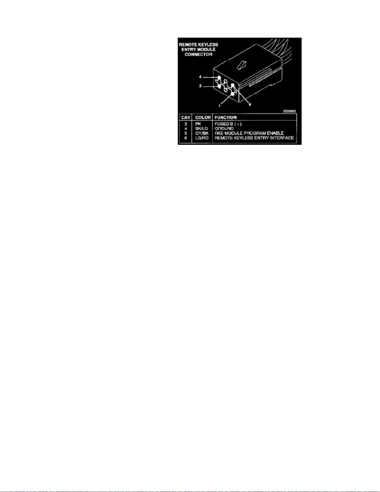
> Relays and Modules > Relays and Modules - Accessories and Optional Equipment > Keyless Entry Module > Component Information > Locations
Page 3

Page 4

> Relays and Modules > Relays and Modules - Accessories and Optional Equipment > Keyless Entry Module > Component Information > Locations > Page 7
Page 5

Page 6

> Relays and Modules > Relays and Modules - Accessories and Optional Equipment > Keyless Entry Module > Component Information > Locations > Page 8
Keyless Entry Module: Adjustments
ten seconds
1. Using a functional key fob transmitter, unlock the vehicle and disarm the Vehicle Theft Security System.2. Insert ignition key into the ignition switch.3. Turn the ignition switch to RUN position without starting engine.4. Using a functional key fob transmitter, press and hold the UNLOCK button for a minimum four seconds (maximum ).5. While holding UNLOCK button, and before passes, press and release the PANIC button. A single chime will sound to verify that the ten seconds
RKE module is set to receive the new Vehicle Access Code(s).
6. Within of the chime, press any button on each new key fob transmitter. After or when ignition switch is turned OFF, the 30 seconds 30 seconds
RKE module will end the programming mode. A single chime will sound to verify that the RKE module will no longer receive additional VehicleAccess Code(s).
7. When Vehicle Access Code(s) programming is complete, turn Ignition Switch to the OFF position and verify RKE system operation using each
key fob.
NOTE:
Only the primary (first two) key fob transmitters will operate the memory seat and mirror systems. If a primary key fob is being replaced,the memory seat and mirror module will require programming.
Page 7

Page 8

> Relays and Modules > Relays and Modules - Accessories and Optional Equipment > Keyless Entry Module > Component Information > Locations > Page 9
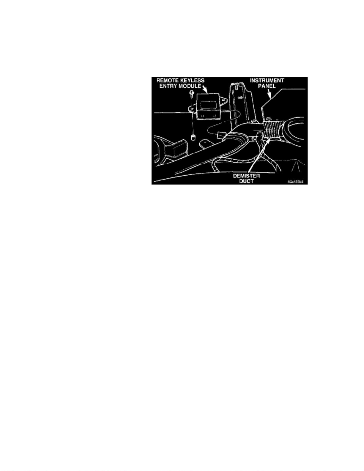
Keyless Entry Module: Service and Repair
REMOVAL
1. Remove instrument panel top cover2. Remove screws holding RKE module to instrument panel.
RKE Module
3. Disconnect wire connector from RKE module.4. Remove the RKE module.
INSTALLATION
- For Installation, reverse the above procedures.
Page 9

Page 10

> Relays and Modules > Relays and Modules - Body and Frame > Keyless Entry Module > Component Information > Locations
Page 11

Page 12
> Relays and Modules > Relays and Modules - Body and Frame > Keyless Entry Module > Component Information > Locations > Page 14
Page 13

Page 14

> Relays and Modules > Relays and Modules - Body and Frame > Keyless Entry Module > Component Information > Locations > Page 15
Keyless Entry Module: Adjustments
ten seconds
1. Using a functional key fob transmitter, unlock the vehicle and disarm the Vehicle Theft Security System.2. Insert ignition key into the ignition switch.3. Turn the ignition switch to RUN position without starting engine.4. Using a functional key fob transmitter, press and hold the UNLOCK button for a minimum four seconds (maximum ).5. While holding UNLOCK button, and before passes, press and release the PANIC button. A single chime will sound to verify that the ten seconds
RKE module is set to receive the new Vehicle Access Code(s).
6. Within of the chime, press any button on each new key fob transmitter. After or when ignition switch is turned OFF, the 30 seconds 30 seconds
RKE module will end the programming mode. A single chime will sound to verify that the RKE module will no longer receive additional VehicleAccess Code(s).
7. When Vehicle Access Code(s) programming is complete, turn Ignition Switch to the OFF position and verify RKE system operation using each
key fob.
NOTE:
Only the primary (first two) key fob transmitters will operate the memory seat and mirror systems. If a primary key fob is being replaced,the memory seat and mirror module will require programming.
Page 15

Page 16
> Relays and Modules > Relays and Modules - Body and Frame > Keyless Entry Module > Component Information > Locations > Page 16
Keyless Entry Module: Service and Repair
REMOVAL
1. Remove instrument panel top cover2. Remove screws holding RKE module to instrument panel.
RKE Module
3. Disconnect wire connector from RKE module.4. Remove the RKE module.
INSTALLATION
- For Installation, reverse the above procedures.
Page 17

Page 18

> Relays and Modules > Relays and Modules - Body and Frame > Power Door Lock Relay > Component Information > Locations
Page 19

Page 20

> Relays and Modules > Relays and Modules - Body and Frame > Power Seat Control Module > Component Information > Technical Service Bulletins > Memory Power Seat - Travel Range
Power Seat Control Module: Technical Service BulletinsMemory Power Seat - Travel Range
NO: 08-44-98
GROUP: Electrical
DATE: Dec. 11, 1998
SUBJECT:Memory Power SeatTravel Range
MODELS:
1996-1999 (NS) Town & Country1996-1999 (GS) Chrysler Voyager1996-1998 (ZJ) Grand Cherokee1996-1998 (ZG) Grand Cherokee (International Market)
DISCUSSION:
The Memory Seat/Mirror Module (MSMM) (on ZJ/ZG the module is for the seat only) detects and remembers where the end of seat travel (called "softstop") is in each direction. A soft stop is set in MSMM memory when the position sensing feedback voltage, controlled by a potentiometer on the motorend, fails to change. The feedback voltage potentiometers vary the position sensing feedback voltage based on seat position/movement (no movement, nochange in position sensing feedback voltage). The seat motor automatically stops at the soft stop on any subsequent movement so the motor does not runinto a stall condition (end of travel).
The soft stop limits will be updated any time the MSMM senses a mechanical stall (such as when something is stuck under or behind the seat that causesthe seat to stop moving). These soft stops can prevent the seat from being able to have memory positions set over the full range of travel. Also, positionsthat were previously programmed to locations beyond an updated soft stop limit will not be recalled as they are "out of range."
When a new MSMM or seat track is installed into a vehicle, the soft stops must be programmed into the MSMM memory for proper operation, the lastparagraph of this TSB explains the procedure to properly set soft stops. Failure to properly set soft stops could result in intermittent memory seatoperation.
There are two potential reasons for intermittent memory functioning of the seats. The first possibility is the soft stops learned by the MSMM may need tobe reset. New soft stops are learned by the MSMM any time movement is restricted. (This could be as simple as hitting an obstruction in the seat's pathor a person shifting their body while a power seat motor is in operation.)
The second reason only applies to NS/GS-vehicles, intermittent operation of the memory seat can be caused by a poor connection at pin 23 of the P34connector which is located near the right side of the steering column. This circuit is used to communicate and control the seat module. This circuit "locksout" movement when the vehicle is not in park and also causes seat position recall when used with the Remote Keyless Entry (RKE) feature. The P34connector should be inspected for fully seated and clean contacts.
To check and reset the soft stop limits in memory, use the control switches on the side of the seat to move the seat in one direction to the end of travel,then energize the seat again in the same direction until it stops and for three additional seconds after it stops. The amount that the seat moved upon thesecond energizing is the amount the soft stop has been reprogrammed. Repeat this procedure for each of the directions of movement (one at a time).
:NOTE
IF THE SEAT TRACK ASSEMBLY OR MSMM HAVE NOT BEEN REPLACED, THIS METHOD OF SOFT STOP RESET LEAVES THECUSTOMER'S SETTINGS PROGRAMMED IN THE MSMM (AS OPPOSED TO USING DIAGNOSTIC MODES 1 AND 2 DESCRIBED INTHE SERVICE MANUAL).
Page 21

POLICY: Information Only
Page 22

> Relays and Modules > Relays and Modules - Body and Frame > Seat Heater Control Module > Component Information > Description and Operation
Seat Heater Control Module: Description and Operation
SYSTEM OPERATION
(HSCM)
The Heated Seat Control Module is an electronic thermostatic module designed to operate the electric seat heater elements. Twomodules are used in the vehicle, one for each front seat. The HSCM for each seat is installed on front portion of each cushion pan. The wireharness connector is secured by an integral clip to the inside surface of the outboard seat cushion frame.
Inputs to the module include the resistor multiplexed seat switch signal (which includes the seat cushion temperature sensor circuits), anignition-switched battery feed, a non-switched battery feed, and a ground. The only HSCM output is the feed for the seat heating elements.
The HSCM cannot be repaired and, if faulty or damaged, it must be replaced.
Page 23

Page 24

> Relays and Modules > Relays and Modules - Body and Frame > Seat Heater Control Module > Component Information > Description and Operation > Page 27
Seat Heater Control Module: Testing and Inspection
Before testing the heated seat control module, test the heated seat switch, the heated seat elements, and the heated seat sensor as described. If testing ofthe heated seat switch, elements, and sensor reveals no problems, proceed as follows.
1. Replace the heated seat control module with a known good unit and test the operation of the heated seats. If OK, discard the faulty heated seat
control module. If not OK, go to Step 2.
2. Test each of the circuits from the heated seat switch, heated seat elements, and heated seat sensor to the heated seat control module. Repair any
short or open circuits as required.
Page 25

Page 26

> Relays and Modules > Relays and Modules - Body and Frame > Seat Heater Control Module > Component Information > Description and Operation > Page 28
Seat Heater Control Module: Service and Repair
REMOVAL
1. Disconnect and isolate the battery negative cable.2. Remove the seat assembly from the vehicle. 3. With seat upside down on bench, remove the wiring harness connector from the module.4. Remove the screws securing the (HSCM) to the underside of the seat cushion pan.5. Remove module from seat cushion pan.
INSTALLATION
For installation, reverse the above procedures.
Page 27

Page 28
> Relays and Modules > Relays and Modules - Brakes and Traction Control > ABS Main Relay > Component Information > Description and Operation
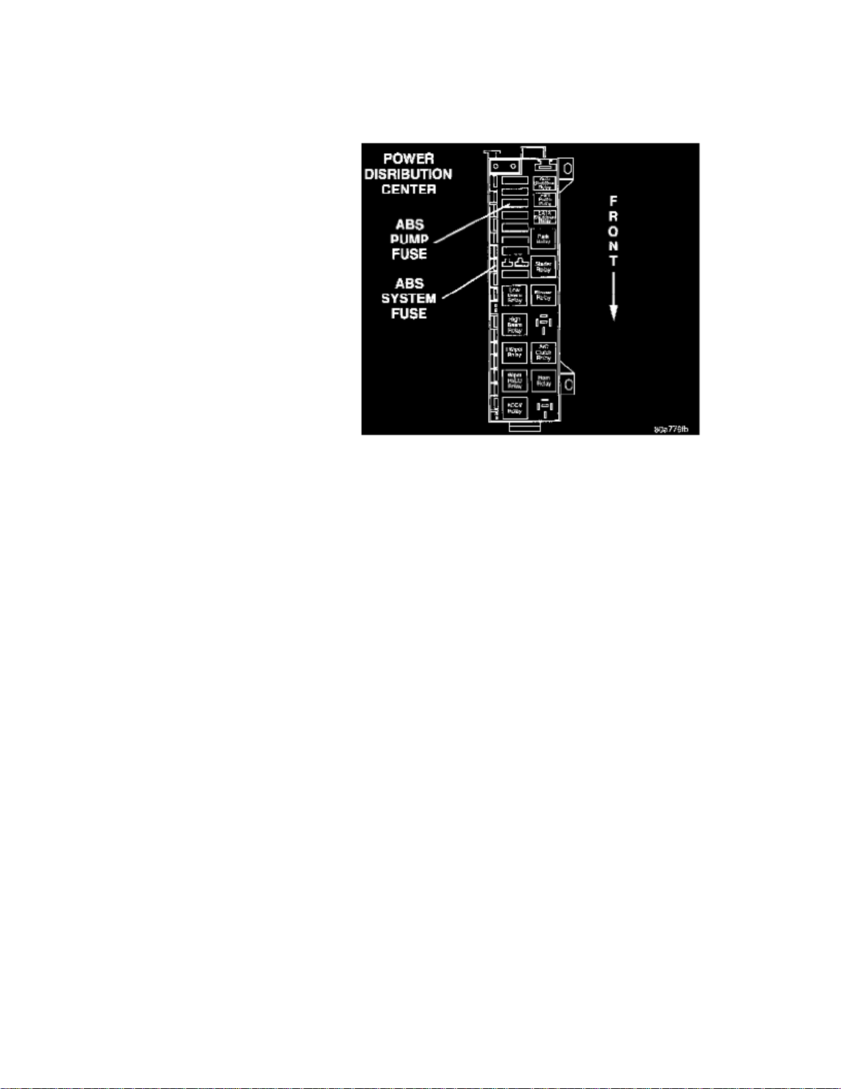
ABS Main Relay: Description and Operation
ABS FUSES
Fuse Locations In Power Distribution Center
(PDC)
The fuse for the ABS pump motor and the ABS system are located in the Power Distribution Center . The PDC is located on the driversside of the engine compartment forward of the strut tower. The fuse for the ABS warning lamp in the instrument panel message center is located inthe junction block.
On vehicles equipped with traction control, the fuse for the traction control switch is also located in the junction block.
The junction block is located on the left hand front cowl panel on the vehicle.
ABS RELAYS
On the Teves Mark 20 Antilock Brake System both the pump motor relay and the system relay are located in the CAB. If either of the relays isdiagnosed as not functioning properly the CAB will need to be replaced.
Page 29

Page 30

> Relays and Modules > Relays and Modules - Brakes and Traction Control > Electronic Brake Control Module > Component Information > Specifications
Electronic Brake Control Module: Specifications
To HCU Mounting Bolts ......................................................................................................................................................................... 2 Nm (17 inch lbs.)
Page 31

Page 32

> Relays and Modules > Relays and Modules - Brakes and Traction Control > Electronic Brake Control Module > Component Information > Specifications > Page 36
Controller Antilock Brakes Location
Page 33

Page 34

> Relays and Modules > Relays and Modules - Brakes and Traction Control > Electronic Brake Control Module > Component Information > Specifications > Page 37
Controller Antilock Brakes Connector
Page 35

Page 36

> Relays and Modules > Relays and Modules - Brakes and Traction Control > Electronic Brake Control Module > Component Information > Specifications > Page 38
Electronic Brake Control Module: Description and Operation
(CAB)
The Controller Antilock Brake is a microprocessor-based device that monitors wheel speeds and controls the antilock functions. The CABcontains two microprocessors that receive identical sensor signals and then independently process the information. The results are then compared tomake sure that they agree. Otherwise, the CAB will turn off the antilock and turn on the Antilock Brake System amber warning lamp.(ABS)
The primary functions of the CAB are to:
- detect wheel locking tendencies
- control fluid pressure modulation to the brakes during antilock stop
- monitor the system for proper operation
- provide communication to the DRB while in diagnostic mode
- store diagnostic information in non-volatile memory
The CAB continuously monitors the speed of each wheel. When a wheel locking tendency is detected, the CAB will command the appropriate valve tomodulate brake fluid pressure in its hydraulic unit. Brake pedal position is maintained during an antilock stop by being a closed system with the use of 2accumulators. The CAB continues to control pressure in individual hydraulic circuits until a wheel locking tendency is no longer present. The CAB turnson the pump motor during an antilock stop.
The antilock brake system is constantly monitored by the CAB for proper operation If the CAB detects a system malfunction, it can disable the antilocksystem and turn on the ABS warning lamp. If the antilock function is disabled, the system will revert to standard base brake system operation.
CAB Inputs Include The Following:
- ABS Warning Lamp
- Diagnostic Communication
- Four Wheel Speed Sensors
- Ignition Switch
- Fused B+
- Stop Lamp Switch
- Traction Control Switch
CAB Outputs Include The Following:
- ABS Warning Light Actuation
- Voltage
- Eight Valves
- Ten Valves With Traction Control
- Diagnostic Communication
- Body Controller Communication
- Traction Control Lamp Illumination
Page 37

Page 38

> Relays and Modules > Relays and Modules - Brakes and Traction Control > Electronic Brake Control Module > Component Information > Service and Repair > Removal
Electronic Brake Control Module: Service and RepairRemoval
1. Disconnect the negative (ground) cable from the battery and isolate cable.2. Using a brake pedal depressor, move and lock the brake pedal to a position past the first inch of pedal travel. This will prevent brake fluid from
draining out of the master cylinder when the brake tubes are removed from the Hydraulic Control Unit .(HCU)
3. Raise vehicle. Vehicle is to be raised and supported on jackstands or on a frame contact type hoist.
Do not apply a 12 volt power source to any terminals of the 25 way HCU connector when disconnected.CAUTION:
CAB 25 Way Connector
Unlocking CAB 25 Way Connector
4. Remove the 25 way connector from the Controller Antilock Brake located on the bottom of the HCU. The 25 way connector is removed(CAB)
from the CAB using the following procedure. Grasp the lock on the 25 way connector and pull it as far out as possible. This will unlock and raisethe 25 way connector from the socket on the CAB.
CAUTION:
Before removing the brake tubes from the HCU, the HCU must be thoroughly cleaned. This must be done to prevent dirt particlesfrom failing into the ports of HCU or entering the brake tubes.
5. Thoroughly clean all surfaces of the HCU, and all brake tube nuts located on the HCU. Use only a solvent such as Mopar Brake Parts Cleaner or
an equivalent to clean the HCU.
Page 39

> Relays and Modules > Relays and Modules - Brakes and Traction Control > Electronic Brake Control Module > Component Information > Service and Repair > Removal >
Page 41
Caravan FWD L4-2.4L VIN B (1998)
Page 40

Brake Tube Connections To HCU
6. Remove the brake tubes (6) from the inlet and outlet ports on the HCU.
HCU To Suspension Cradle Mounting Bolts
7. Remove the 3 bolts attaching the HCU mounting bracket to the front suspension crossmember.8. Remove HCU and the mounting bracket as a unit from the vehicle.
Page 41

> Relays and Modules > Relays and Modules - Brakes and Traction Control > Electronic Brake Control Module > Component Information > Service and Repair > Removal >
Page 42
Caravan FWD L4-2.4L VIN B (1998)
HCU Mounting Bolts
9. Remove the 3 bolts mounting the HCU to the mounting bracket. Separate the HCU from the mounting bracket.
Page 42

Pump Motor To CAB Wiring Harness
10. Unplug the pump motor wiring harness from the CAB.
CAB Attaching Bolts
11. Remove the 4 bolts attaching the CAB to the valve block of the HCU.
Page 43

Remove/Install CAB
12. Remove the CAB from the valve block of the HCU.
Page 44

> Relays and Modules > Relays and Modules - Brakes and Traction Control > Electronic Brake Control Module > Component Information > Service and Repair > Removal > Page 43
Electronic Brake Control Module: Service and RepairInstallation
Remove/Install CAB
1. Install the Controller Antilock Brake on the valve block of the Hydraulic Control Unit .(CAB) (HCU)
CAB Attaching Bolts
2. Install the 4 bolts mounting the CAB to the valve block of the HCU. Tighten the CAB mounting bolts to a torque of .2 Nm (17 inch lbs.)
Page 45

> Relays and Modules > Relays and Modules - Brakes and Traction Control > Electronic Brake Control Module > Component Information > Service and Repair > Removal >
Page 44
Caravan FWD L4-2.4L VIN B (1998)
Pump Motor To CAB Wiring Harness
3. Plug the pump/motor wiring harness into the CAB.
Page 46

HCU Mounting Bolts
4. Install the HCU on the mounting bracket. Install the 3 bolts attaching the HCU to the mounting bracket. Tighten the 3 mounting bolts to a torque
of .11 Nm (97 inch lbs.)
CAUTION:
The HCU mounting bracket to front suspension cradle mounting bolts have a unique corrosion protection coating and a specialaluminum washer. For this reason, only the original, or original equipment Mopar replacement bolts can be used to mount the HCU bracket to thefront suspension crossmember.
HCU To Suspension Cradle Mounting Bolts
5. Install the HCU and its mounting bracket as an assembly on the front suspension crossmember. Install the 3 bolts attaching the HCU bracket to the
crossmember. Tighten the 3 mounting bolts to a torque of .28 Nm (250 inch lbs.)
CAUTION:
Because of the flexible section in the primary and secondary brake tubes, and the brake tubes between the HCU and theproportioning valve, the brake tubes must be held in proper orientation when tightened and torqued. These tubes must not contact each other orother vehicle components when installed.
Page 47

> Relays and Modules > Relays and Modules - Brakes and Traction Control > Electronic Brake Control Module > Component Information > Service and Repair > Removal >
Page 45
Caravan FWD L4-2.4L VIN B (1998)
Brake Tube Connections To HCU
Page 48

CAUTION:
When installing the chassis brake tubes on the HCU valve block, they must be located correctly in the valve block to ensure properABS operation. Refer to image for the correct chassis brake tube locations.
The chassis brake tube attachment locations to the HCU, are marked on the bottom of the HCU mounting bracket.NOTE:
6. Install the 6 chassis brake tubes into their correct port locations on the HCU valve block as shown. Tighten the tube nuts to a torque of 17 Nm
.(145 inch lbs.)
Before installing the 25 way connector in the CAB be sure the seal is properly installed in the connector.NOTE:
Unlocking CAB 25 Way Connector
7. Install the 25 way connector on the CAB using the following procedure. Position the 25 way connector in the socket of the CAB and carefully
push it down as far as possible. When connector is fully seated by hand into the CAB socket, push in the connector lock. This will pull theconnector into the socket of the CAB and lock it in the installed position.
Brake Tube Routing Clips
8. Install the routing clips on the brake tubes.9. Lower vehicle.
Page 49

10. Connect negative cable back on negative post of the battery.11. Bleed the base brakes and the ABS brakes hydraulic system. 12. Road test vehicle to ensure proper operation of the base and ABS brake systems.
Page 50

> Relays and Modules > Relays and Modules - Cooling System > Radiator Cooling Fan Control Module Relay > Component Information > Technical Service Bulletins > Cooling System - Manual Revisions
Radiator Cooling Fan Control Module Relay: Technical Service BulletinsCooling System - Manual Revisions
NUMBER: 26-11-97G
GROUP: Miscellaneous
DATE: November, 1997
REVISIONS ARE HIGHLIGHTED WITH BLACK BARS IN THE MARGIN
Models:1998 2.0L/2.4L/2.5L SFI Engine Diagnostic Manual - Publication Number 81-699-97108
DESCRIPTION OF CHANGES
Revisions to the radiator fan control relay test
Page 51

> Relays and Modules > Relays and Modules - Cooling System > Radiator Cooling Fan Control Module Relay > Component Information > Technical Service Bulletins >
Cooling System - Manual Revisions > Page 51
Caravan FWD L4-2.4L VIN B (1998)
Page 52

Page 53

98
Page 54

> Relays and Modules > Relays and Modules - Cooling System > Radiator Cooling Fan Motor Relay > Component Information > Technical Service Bulletins > Recalls: > 771 > May > 98 > Campaign - Radiator Fan Relay and
PCM
Technical Service Bulletin # 771
Campaign - Radiator Fan Relay and PCM
No. 771
May, 1998
To: All Dodge and Chrysler-Plymouth Dealers
Subject:Customer Satisfaction Notification # 771 -- Radiator Fan Relay and Reprogram Powertrain Control Module
Models:1998 Model Year Dodge Caravan and Grand Caravan; Plymouth Voyager and Grand Voyager; and Chrysler Town & Country (NS) Vehicles EquippedWith a 2.4L, 3.3L or 3.8L Engine ("B", "G","R" or "L" in the 8th VIN Position) Built Through:
^ November 26, 1997 (MDH 112623) at the St. Louis South Assembly Plant ("B" in the 11th VIN Position)
^ December 1, 1997 (MDH 120109) at the Windsor Assembly Plant ("R" in the 11th VIN Position)
The radiator fan relay on about 150,000 of the above listed vehicles, may not turn on the radiator cooling fans. This may cause the engine to overheat. Tocorrect this condition, the radiator fan relay must be replaced and the Powertrain Control Module (PCM) must be reprogrammed (flashed).
Dealer Notification & Vehicle List
All dealers will receive a copy of this dealer notification letter by first class mail. Each dealer to whom involved vehicles were invoiced (or the currentdealer at the same street address) will receive a list of their involved vehicles. The Vehicle List is arranged in Vehicle Identification Number (VIN)sequence. Owners known to Chrysler are also listed. The lists are for dealer reference in arranging for service of involved vehicles.
DIAL System Functions 53 and VIP
All involved vehicles will be entered to DIAL System Functions 53 and VIP at the time of notification mailing for dealer inquiry as needed.
Function 53 provides involved dealers with an updated VIN list of incomplete vehicles. The customer name, address and phone number is listed ifknown. Completed vehicles are removed from Function 53 within several days of repair claim submission. To use this system, type "53" at the "ENTERFUNCTION" prompt, then type "ORD771".
Parts
:IMPORTANT
A quantity of parts will be distributed initially and billed to all involved dealers. This quantity will cover a portion of the total vehicles involved.Additional parts may be ordered as needed to support customer demand.
Each involved dealer, to whom vehicles in the notification were invoiced (or the current dealer at the same street address), will receive enough RadiatorFan Relay Packages, PN CEP07710, to service about 25% of those vehicles.
Each parts package contains the following components:
Quantity Description
1 Radiator Fan Relay
2 Screws
Page 55

> Relays and Modules > Relays and Modules - Cooling System > Radiator Cooling Fan Motor Relay > Component Information > Technical Service Bulletins > Recalls: > 771
> May > 98 > Campaign - Radiator Fan Relay and PCM > Page 60
Caravan FWD L4-2.4L VIN B (1998)
1 Label, Authorized Software Update
1 Label Authorized Modifications
Owner Notification and Service Scheduling
All involved vehicle owners known to Chrysler are being notified of the service requirement by first class mail. They are requested to schedule a serviceappointment with their dealer. A copy of the owner notification letter is included.
Enclosed with each owner notification is an Owner Notification Form. The involved vehicle and notification are identified on the form for owner ordealer reference as needed.
Page 56

Completion Reporting and Reimbursement
Claims for vehicles which have been serviced must be submitted on the DIAL System. Claims submitted will be used by Chrysler to record notificationservice completions and provide dealer payments.
Use one of the following labor operation numbers and time allowances:
Labor Operation Time
Number Allowance
Replace radiator fan relay and check PCM 08771182 0.3 hours
Replace radiator fan relay and reprogram PCM08771183 0.7 hours
Add the cost of the parts package plus applicable dealer allowance to your claim.
: Note
See the Warranty Administration Manual, Recall Claim Processing Section for complete claim processing instructions.
Parts Return
Not required.
Vehicle Not Available
If a vehicle is not available for service for a known reason, let us know by filling out the pre-addressed Vehicle Disposition Form portion of the OwnerNotification Form or describe the reason on a postcard and mail to:
Chrysler CorporationCIMS 482-00-85800 Chrysler Drive EastAuburn Hills, Michigan 48326-2757
Following the above procedures will expedite the processing of your claim.
If you have any questions or need assistance in completing this action, please contact your Zone Service Office.
A. Replace Radiator Fan Relay
1. With the ignition key in the OFF position, disconnect the battery.
Note:
To enhance customer satisfaction, remember to reset the clock when you have completed the service procedure.
2. Remove the two (2) screws that attach the air inlet resonator to the upper radiator support.
3. Disconnect the upper and lower air inlet hoses from the resonator and remove the resonator.
4. Remove the air cleaner housing.
Page 57

> Relays and Modules > Relays and Modules - Cooling System > Radiator Cooling Fan Motor Relay > Component Information > Technical Service Bulletins > Recalls: > 771
> May > 98 > Campaign - Radiator Fan Relay and PCM > Page 61
Caravan FWD L4-2.4L VIN B (1998)
Page 58

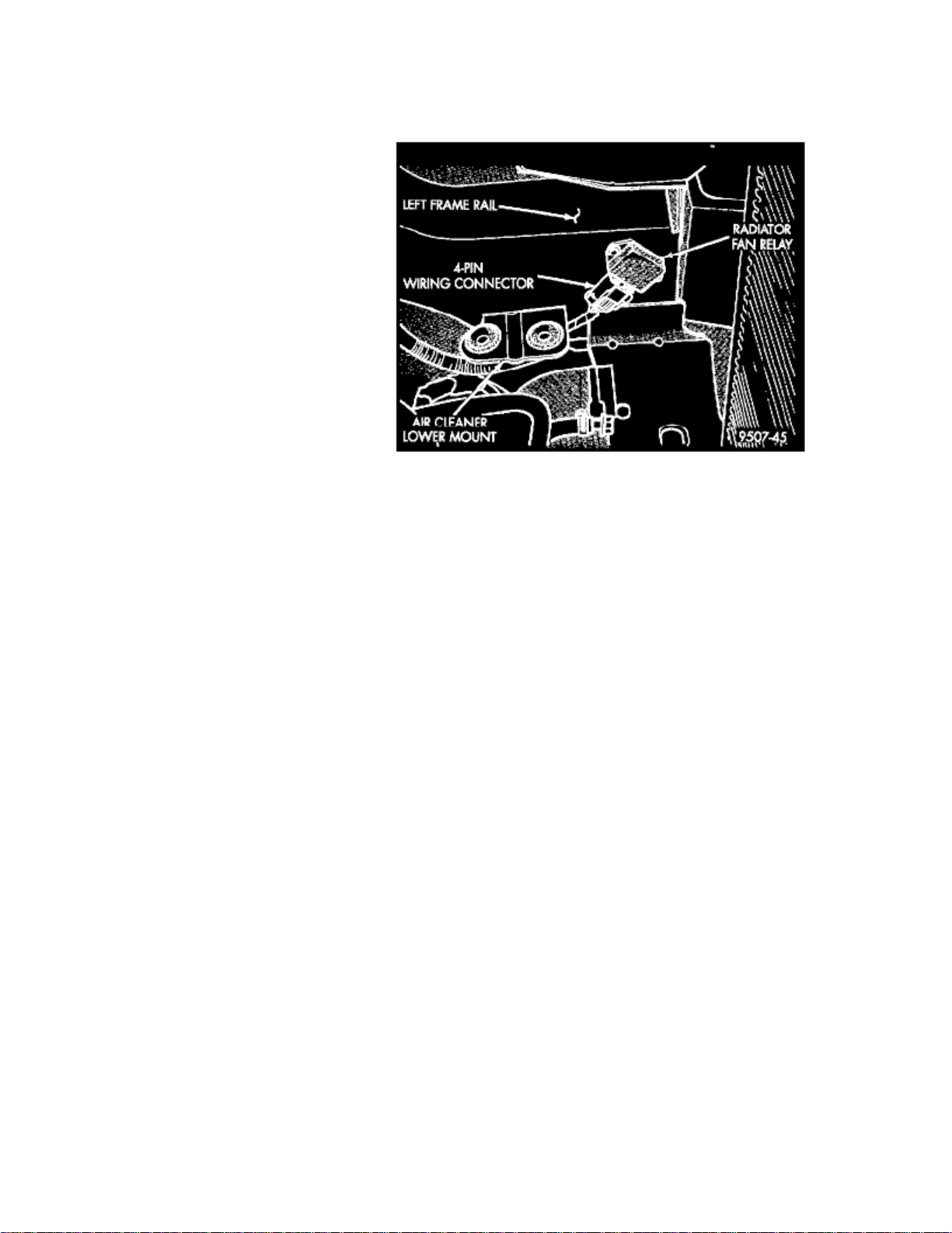
5. Locate the radiator cooling fan relay on the left front inner frame rail just behind the radiator (Figure 1).
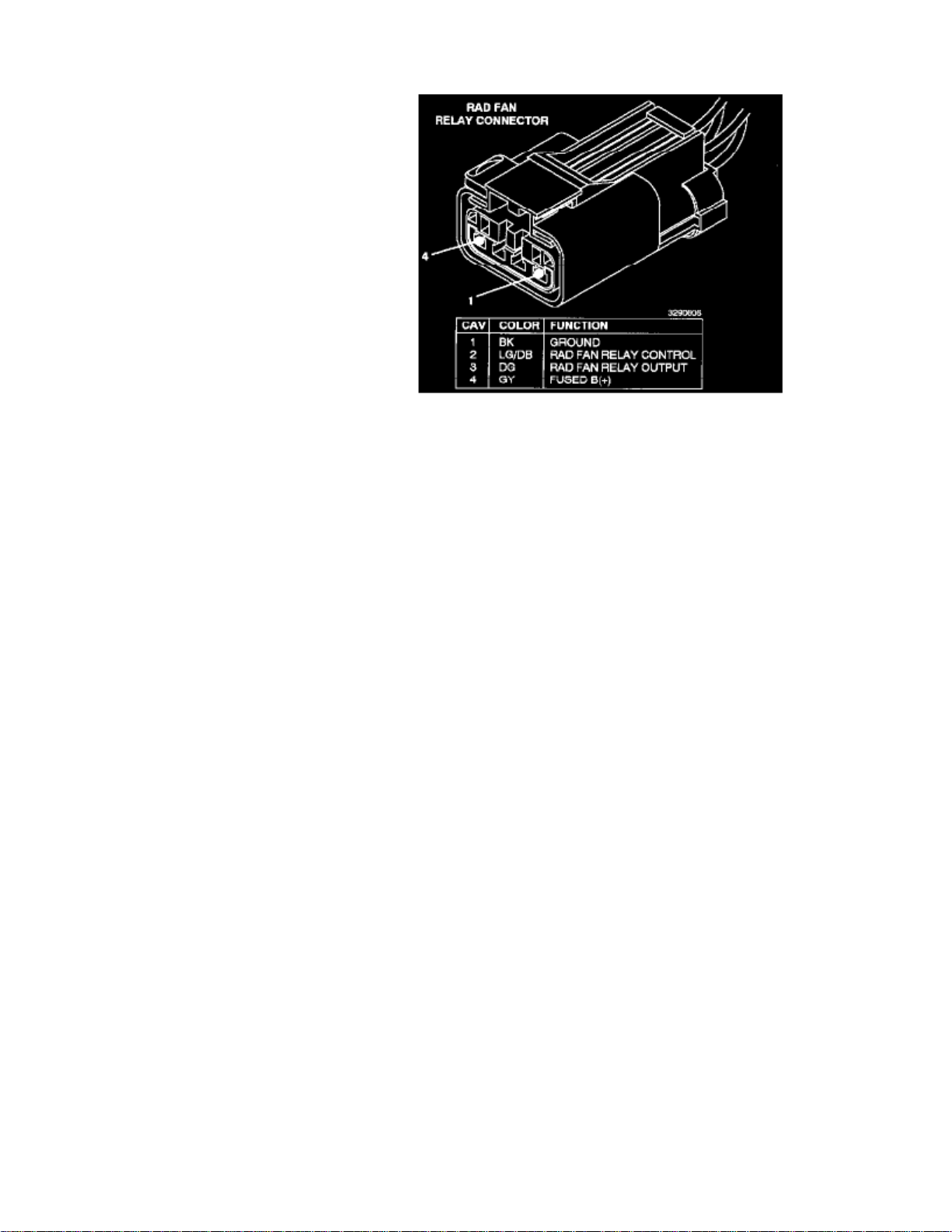
6. Disconnect the radiator fan relay wiring connector.
7. Remove the radiator fan relay. Discard the relay and the attaching screws.
8. Install the new radiator fan relay using the supplied screws. Tighten the screws to 35 in-lbs (4 N.m).
CAUTION:
Do not over torque screws. To ensure heat transfer and proper operation, the new radiator fan relay must be installed using both of the providedscrews.
9. Connect the radiator fan relay electrical connector. Slide the red latch to the locked position.
10. Install the air cleaner housing.
11. Install the resonator assembly and connect the upper and lower air inlet hoses.
12. Install the resonator to upper radiator support screws. Tighten the screws securely.
13. Connect the negative battery cable.
B. Reprogram the PCM
1. Connect the MDS (Mopar Diagnostic System) and the DRB III(R) (Scan Tool) to the vehicle and power them up.
NOTE:
The Mopar Diagnostic System is required to perform the PCM flash. The system must be operating with RELEASE 21 or higher and TIL CDRELEASE 1157 or higher must be installed.
2. Use the arrow keys and select # 2 -- MDS DIAGNOSTICS on the DRB III MAIN MENU Screen.
3. Use the arrow keys and select DIAGNOSTICS MENU on the MDS, then press NEXT MENU.
4. Use the arrow keys and select VEHICLE CONTROLLER PROGRAMMING on the MDS, then press NEXT MENU.
5.
Page 59

> Relays and Modules > Relays and Modules - Cooling System > Radiator Cooling Fan Motor Relay > Component Information > Technical Service Bulletins > Recalls: > 771
> May > 98 > Campaign - Radiator Fan Relay and PCM > Page 62
Caravan FWD L4-2.4L VIN B (1998)
Use the arrow keys and select PROGRAMMING OF ALL OTHER CONTROLLERS USING MDS & DRB III on the MDS, then press NEXTMENU.
6. Follow the steps presented on the MDS and DRB III which will allow the DRB III to obtain the current part number of the PCM.
7.
The MDS will display the part number of the PCM on the vehicle and the appropriate replacement part number then press NEXT MENU to beginprogramming.
NOTE:
If the PCM on the vehicle has already been updated or reprogrammed, a NO UPDATES AVAILABLE message will be displayed. Verify that thepart number of the PCM (or previously installed authorized software update label) matches the part number displayed on the MDS and then continuewith Section D.
8. The MDS and DRB III will prompt for any operator action needed during the remainder of the programming process.
Page 60

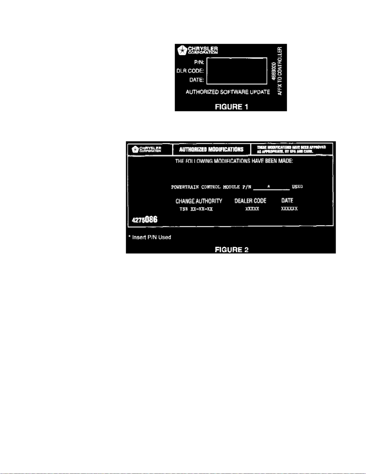
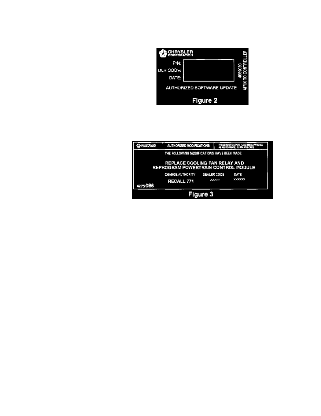
C. Install Authorized Software Update Label
1.
Type or print (with a ball point pen) the necessary information on the "Authorized Software Update" label (Figure 2) and attach it to the PCM.Cover the label with the clear plastic portion of the label.
D. Install the Authorized Modification Label
1.
Type or print (with a ball point pen) the following information on the Authorized Modification Label and attach the label near the VECI label(Figure 3).
Dealer Service Instructions
IMPORTANT
DEALER SERVICE INSTRUCTIONSCustomer Satisfaction Notification # 771Radiator Fan Relay and Reprogram PCM
^
This service requirement applies only to 1998 model year Dodge Caravan and Grand Caravan; Plymouth Voyager and Grand Voyager; and ChryslerTown & Country (NS) vehicles equipped with a 2.4L, 3.3L or 3.8L engine ("B", "G", "R" or "L" in the 8th VIN position) built through:
^ November 26, 1997 (MDH 112623) at the St. Louis South Assembly Plant ("B" in the 11th VIN position)
^ December 1, 1997 (MDH 120109) at the Windsor Assembly Plant ("R" in the 11th VIN position)
^
The radiator fan relay on the above listed vehicles, may not turn on the radiator cooling fans. This may cause the engine to overheat. To correct thiscondition, the radiator fan relay must be replaced and the Powertrain Control Module (PCM) must be reprogrammed (flashed).
^
Effective immediately all repairs on involved vehicles are to be performed according to this Customer Satisfaction Notification. The Labor OperationNumber for TSB 18-33-97 is being canceled.
Parts Packages:
^
Each involved dealer, to whom vehicles in this notification were invoiced, will receive enough Radiator Fan Relay Packages to service about 25% ofthose vehicles.
Owner Letter
Page 61

> Relays and Modules > Relays and Modules - Cooling System > Radiator Cooling Fan Motor Relay > Component Information > Technical Service Bulletins > Recalls: > 771
> May > 98 > Campaign - Radiator Fan Relay and PCM > Page 63
Caravan FWD L4-2.4L VIN B (1998)
CUSTOMER SATISFACTION NOTIFICATION TO REPLACE YOUR VEHICLE'S
RADIATOR FAN RELAY AND REPROGRAM THE POWER TRAIN CONTROL MODULE
Dear Chrysler Minivan Owner:
The satisfaction of our customers is very important to Chrysler. Because of this, we are requesting owners of some 1998 Dodge Caravan and GrandCaravan; Plymouth Voyager and Grand Voyager; and Chrysler Town & Country minivans equipped with a 2.4L, 3.3L or 3.8L engine, to return them totheir dealer for a special service.
The problem is...
The radiator fan relay on your minivan (identified on the enclosed form), may not turn on the radiator cooling fans. This may cause the engine to
Page 62

overheat.
What Chrysler and your dealer will do...
Chrysler will repair your minivan free of charge (parts and labor). To do this, your dealer will replace the radiator fan relay and reprogram the powertraincontrol module. The work will take about one hour to complete. However, additional time may be necessary depending on how dealer appointments arescheduled and processed.
What you must do...
^
Simply contact your dealer to schedule a service appointment. Ask the dealer to hold the parts for your vehicle or to order them before yourappointment.
^ Bring the enclosed Owner Notification Form with you to your dealer. It explains the required service to your dealer.
If you need help...
If you have trouble getting your vehicle repaired, please call the Chrysler Customer Center, toll free, at 1-800-992-1997. A representative will assist youin getting your vehicle repaired.
We're sorry for any inconvenience, but we believe that this special service will help to ensure your continuing satisfaction with your vehicle. Thanks foryour attention to this important matter.
Page 63

Page 64

> Relays and Modules > Relays and Modules - Cooling System > Radiator Cooling Fan Motor Relay > Component Information > Technical Service Bulletins > Customer Interest: > 18-33-97 > Dec > 97 > PCM - Improper
Cooling Fan Relay Actuation
Radiator Cooling Fan Motor Relay: Customer InterestPCM - Improper Cooling Fan Relay Actuation
NO: 18-33-97
GROUP: Vehicle Performance
DATE: Dec. 31, 1997
SUBJECT: Improper Cooling Fan Relay Actuation
MODELS: 1998 (NS) Town & Country/Caravan/Voyager
: NOTE
THIS BULLETIN APPLIES TO VEHICLES EQUIPPED WITH A 2.4L, 3.3L OR 3.8L ENGINE BUILT PRIOR TO DEC. 1, 1997 (MDH 1201XX).
DISCUSSION:The software within the powertrain control module (PCM) may not operate or drive the solid state relay for the radiator fan correctly. The vehicle couldeventually exhibit an overheat condition due to cooling fan relay failure.
: NOTE
ALL IN STOCK OR IN TRANSIT VEHICLES BUILT PRIOR TO THE ABOVE CLEAN POINT SHOULD BE FLASH UPDATED PRIOR TOCUSTOMER DELIVERY.
EQUIPMENT/PARTS REQUIRED:
1 CH6000 Scan Tool (DRB III)
1 CH7035 General Purpose Interface Bus Cable (GPIB)
1 CH7000/7001 J1962 Cable
1 04669020 Label - Authorized Software Update
1 04275086 Label - Authorized Modification
: NOTE
THE MDS AND DRB III ARE REQUIRED TO PERFORM THIS REPAIR AND THE SYSTEM MUST BE OPERATING WITH RELEASE 21OR HIGHER AND TIL CD RELEASE 1146 OR HIGHER MUST BE INSTALLED.
1. Connect the MDS (Mopar Diagnostic System) and DRB III (Scan Tool) to the vehicle and power them up.
2. Use the arrow keys and select # 2 MDS DIAGNOSTICS on the DRB III MAIN MENU Screen.
3. Use the arrow keys and select DIAGNOSTIC MENU on the MDS, then press NEXT MENU.
4. Use the arrow keys and select VEHICLE CONTROLLER PROGRAMMING on the MDS, then press NEXT MENU.
5.
Use the arrow keys and select PROGRAMMING OF ALL OTHER CONTROLLERS USING MDS & DRB III on the MDS, then press NEXTMENU.
Page 65

> Relays and Modules > Relays and Modules - Cooling System > Radiator Cooling Fan Motor Relay > Component Information > Technical Service Bulletins > Customer
Interest: > 18-33-97 > Dec > 97 > PCM - Improper Cooling Fan Relay Actuation > Page 69
Caravan FWD L4-2.4L VIN B (1998)
REPAIR PROCEDURE:This bulletin involves selectively erasing and reprogramming the Powertrain Control Module (PCM) with new software (calibration changes).
6. Follow the steps presented on the MDS and DRB III which will allow the DRB III to obtain the current part number of the PCM.
7.
The MDS will display the part number of the PCM on the vehicle and the appropriate replacement part number, then press NEXT MENU to beginprogramming.
If the PCM on the vehicle has already been updated or programmed, a NO UPDATES AVAILABLE message will be displayed. Check the partnumber of the PCM on the vehicle and compare it to the part number displayed. If the PCM has already been updated, then another conditionexists that will require further diagnosis and repair.
8. The MDS and DRB III will prompt for any operator action needed during the remainder of the programming process.
: NOTE
THE FOLLOWING STEPS ARE REQUIRED BY LAW.
Page 66

9.
Type the necessary information on the "Authorized Software Update Label" p/n 04669020 (Figure 1). Attach the label to the PCM and cover thelabel with the clear plastic overlay.
10. Type the necessary information on the "Authorized Modification Label" p/n 04275086 and attach the label near the VECI Label (Figure 2).
POLICY:Reimbursable within the provisions of the warranty.
TIME ALLOWANCE:Labor Operation No:
08-19-49-90 0.5 Hrs.
FAILURE CODE: FM - Flash Module
Page 67

Page 68

> Relays and Modules > Relays and Modules - Cooling System > Radiator Cooling Fan Motor Relay > Component Information > Technical Service Bulletins > All Technical Service Bulletins for Radiator Cooling Fan Motor
Relay: > 771 > May > 98 > Campaign - Radiator Fan Relay and PCM
Technical Service Bulletin # 771
Campaign - Radiator Fan Relay and PCM
No. 771
May, 1998
To: All Dodge and Chrysler-Plymouth Dealers
Subject:Customer Satisfaction Notification # 771 -- Radiator Fan Relay and Reprogram Powertrain Control Module
Models:1998 Model Year Dodge Caravan and Grand Caravan; Plymouth Voyager and Grand Voyager; and Chrysler Town & Country (NS) Vehicles EquippedWith a 2.4L, 3.3L or 3.8L Engine ("B", "G","R" or "L" in the 8th VIN Position) Built Through:
^ November 26, 1997 (MDH 112623) at the St. Louis South Assembly Plant ("B" in the 11th VIN Position)
^ December 1, 1997 (MDH 120109) at the Windsor Assembly Plant ("R" in the 11th VIN Position)
The radiator fan relay on about 150,000 of the above listed vehicles, may not turn on the radiator cooling fans. This may cause the engine to overheat. Tocorrect this condition, the radiator fan relay must be replaced and the Powertrain Control Module (PCM) must be reprogrammed (flashed).
Dealer Notification & Vehicle List
All dealers will receive a copy of this dealer notification letter by first class mail. Each dealer to whom involved vehicles were invoiced (or the currentdealer at the same street address) will receive a list of their involved vehicles. The Vehicle List is arranged in Vehicle Identification Number (VIN)sequence. Owners known to Chrysler are also listed. The lists are for dealer reference in arranging for service of involved vehicles.
DIAL System Functions 53 and VIP
All involved vehicles will be entered to DIAL System Functions 53 and VIP at the time of notification mailing for dealer inquiry as needed.
Function 53 provides involved dealers with an updated VIN list of incomplete vehicles. The customer name, address and phone number is listed ifknown. Completed vehicles are removed from Function 53 within several days of repair claim submission. To use this system, type "53" at the "ENTERFUNCTION" prompt, then type "ORD771".
Parts
:IMPORTANT
A quantity of parts will be distributed initially and billed to all involved dealers. This quantity will cover a portion of the total vehicles involved.Additional parts may be ordered as needed to support customer demand.
Each involved dealer, to whom vehicles in the notification were invoiced (or the current dealer at the same street address), will receive enough RadiatorFan Relay Packages, PN CEP07710, to service about 25% of those vehicles.
Each parts package contains the following components:
Quantity Description
1 Radiator Fan Relay
2 Screws
Page 69

> Relays and Modules > Relays and Modules - Cooling System > Radiator Cooling Fan Motor Relay > Component Information > Technical Service Bulletins > All Technical
Service Bulletins for Radiator Cooling Fan Motor Relay: > 771 > May > 98 > Campaign - Radiator Fan Relay and PCM > Page 75
Caravan FWD L4-2.4L VIN B (1998)
1 Label, Authorized Software Update
1 Label Authorized Modifications
Owner Notification and Service Scheduling
All involved vehicle owners known to Chrysler are being notified of the service requirement by first class mail. They are requested to schedule a serviceappointment with their dealer. A copy of the owner notification letter is included.
Enclosed with each owner notification is an Owner Notification Form. The involved vehicle and notification are identified on the form for owner ordealer reference as needed.
Page 70

Completion Reporting and Reimbursement
Claims for vehicles which have been serviced must be submitted on the DIAL System. Claims submitted will be used by Chrysler to record notificationservice completions and provide dealer payments.
Use one of the following labor operation numbers and time allowances:
Labor Operation Time
Number Allowance
Replace radiator fan relay and check PCM 08771182 0.3 hours
Replace radiator fan relay and reprogram PCM08771183 0.7 hours
Add the cost of the parts package plus applicable dealer allowance to your claim.
: Note
See the Warranty Administration Manual, Recall Claim Processing Section for complete claim processing instructions.
Parts Return
Not required.
Vehicle Not Available
If a vehicle is not available for service for a known reason, let us know by filling out the pre-addressed Vehicle Disposition Form portion of the OwnerNotification Form or describe the reason on a postcard and mail to:
Chrysler CorporationCIMS 482-00-85800 Chrysler Drive EastAuburn Hills, Michigan 48326-2757
Following the above procedures will expedite the processing of your claim.
If you have any questions or need assistance in completing this action, please contact your Zone Service Office.
A. Replace Radiator Fan Relay
1. With the ignition key in the OFF position, disconnect the battery.
Note:
To enhance customer satisfaction, remember to reset the clock when you have completed the service procedure.
2. Remove the two (2) screws that attach the air inlet resonator to the upper radiator support.
3. Disconnect the upper and lower air inlet hoses from the resonator and remove the resonator.
4. Remove the air cleaner housing.
Page 71

> Relays and Modules > Relays and Modules - Cooling System > Radiator Cooling Fan Motor Relay > Component Information > Technical Service Bulletins > All Technical
Service Bulletins for Radiator Cooling Fan Motor Relay: > 771 > May > 98 > Campaign - Radiator Fan Relay and PCM > Page 76
Caravan FWD L4-2.4L VIN B (1998)
Page 72

5. Locate the radiator cooling fan relay on the left front inner frame rail just behind the radiator (Figure 1).
6. Disconnect the radiator fan relay wiring connector.
7. Remove the radiator fan relay. Discard the relay and the attaching screws.
8. Install the new radiator fan relay using the supplied screws. Tighten the screws to 35 in-lbs (4 N.m).
CAUTION:
Do not over torque screws. To ensure heat transfer and proper operation, the new radiator fan relay must be installed using both of the providedscrews.
9. Connect the radiator fan relay electrical connector. Slide the red latch to the locked position.
10. Install the air cleaner housing.
11. Install the resonator assembly and connect the upper and lower air inlet hoses.
12. Install the resonator to upper radiator support screws. Tighten the screws securely.
13. Connect the negative battery cable.
B. Reprogram the PCM
1. Connect the MDS (Mopar Diagnostic System) and the DRB III(R) (Scan Tool) to the vehicle and power them up.
NOTE:
The Mopar Diagnostic System is required to perform the PCM flash. The system must be operating with RELEASE 21 or higher and TIL CDRELEASE 1157 or higher must be installed.
2. Use the arrow keys and select # 2 -- MDS DIAGNOSTICS on the DRB III MAIN MENU Screen.
3. Use the arrow keys and select DIAGNOSTICS MENU on the MDS, then press NEXT MENU.
4. Use the arrow keys and select VEHICLE CONTROLLER PROGRAMMING on the MDS, then press NEXT MENU.
5.
Page 73

> Relays and Modules > Relays and Modules - Cooling System > Radiator Cooling Fan Motor Relay > Component Information > Technical Service Bulletins > All Technical
Service Bulletins for Radiator Cooling Fan Motor Relay: > 771 > May > 98 > Campaign - Radiator Fan Relay and PCM > Page 77
Caravan FWD L4-2.4L VIN B (1998)
Use the arrow keys and select PROGRAMMING OF ALL OTHER CONTROLLERS USING MDS & DRB III on the MDS, then press NEXTMENU.
6. Follow the steps presented on the MDS and DRB III which will allow the DRB III to obtain the current part number of the PCM.
7.
The MDS will display the part number of the PCM on the vehicle and the appropriate replacement part number then press NEXT MENU to beginprogramming.
NOTE:
If the PCM on the vehicle has already been updated or reprogrammed, a NO UPDATES AVAILABLE message will be displayed. Verify that thepart number of the PCM (or previously installed authorized software update label) matches the part number displayed on the MDS and then continuewith Section D.
8. The MDS and DRB III will prompt for any operator action needed during the remainder of the programming process.
Page 74

C. Install Authorized Software Update Label
1.
Type or print (with a ball point pen) the necessary information on the "Authorized Software Update" label (Figure 2) and attach it to the PCM.Cover the label with the clear plastic portion of the label.
D. Install the Authorized Modification Label
1.
Type or print (with a ball point pen) the following information on the Authorized Modification Label and attach the label near the VECI label(Figure 3).
Dealer Service Instructions
IMPORTANT
DEALER SERVICE INSTRUCTIONSCustomer Satisfaction Notification # 771Radiator Fan Relay and Reprogram PCM
^
This service requirement applies only to 1998 model year Dodge Caravan and Grand Caravan; Plymouth Voyager and Grand Voyager; and ChryslerTown & Country (NS) vehicles equipped with a 2.4L, 3.3L or 3.8L engine ("B", "G", "R" or "L" in the 8th VIN position) built through:
^ November 26, 1997 (MDH 112623) at the St. Louis South Assembly Plant ("B" in the 11th VIN position)
^ December 1, 1997 (MDH 120109) at the Windsor Assembly Plant ("R" in the 11th VIN position)
^
The radiator fan relay on the above listed vehicles, may not turn on the radiator cooling fans. This may cause the engine to overheat. To correct thiscondition, the radiator fan relay must be replaced and the Powertrain Control Module (PCM) must be reprogrammed (flashed).
^
Effective immediately all repairs on involved vehicles are to be performed according to this Customer Satisfaction Notification. The Labor OperationNumber for TSB 18-33-97 is being canceled.
Parts Packages:
^
Each involved dealer, to whom vehicles in this notification were invoiced, will receive enough Radiator Fan Relay Packages to service about 25% ofthose vehicles.
Owner Letter
Page 75

> Relays and Modules > Relays and Modules - Cooling System > Radiator Cooling Fan Motor Relay > Component Information > Technical Service Bulletins > All Technical
Service Bulletins for Radiator Cooling Fan Motor Relay: > 771 > May > 98 > Campaign - Radiator Fan Relay and PCM > Page 78
Caravan FWD L4-2.4L VIN B (1998)
CUSTOMER SATISFACTION NOTIFICATION TO REPLACE YOUR VEHICLE'S
RADIATOR FAN RELAY AND REPROGRAM THE POWER TRAIN CONTROL MODULE
Dear Chrysler Minivan Owner:
The satisfaction of our customers is very important to Chrysler. Because of this, we are requesting owners of some 1998 Dodge Caravan and GrandCaravan; Plymouth Voyager and Grand Voyager; and Chrysler Town & Country minivans equipped with a 2.4L, 3.3L or 3.8L engine, to return them totheir dealer for a special service.
The problem is...
The radiator fan relay on your minivan (identified on the enclosed form), may not turn on the radiator cooling fans. This may cause the engine to
Page 76

overheat.
What Chrysler and your dealer will do...
Chrysler will repair your minivan free of charge (parts and labor). To do this, your dealer will replace the radiator fan relay and reprogram the powertraincontrol module. The work will take about one hour to complete. However, additional time may be necessary depending on how dealer appointments arescheduled and processed.
What you must do...
^
Simply contact your dealer to schedule a service appointment. Ask the dealer to hold the parts for your vehicle or to order them before yourappointment.
^ Bring the enclosed Owner Notification Form with you to your dealer. It explains the required service to your dealer.
If you need help...
If you have trouble getting your vehicle repaired, please call the Chrysler Customer Center, toll free, at 1-800-992-1997. A representative will assist youin getting your vehicle repaired.
We're sorry for any inconvenience, but we believe that this special service will help to ensure your continuing satisfaction with your vehicle. Thanks foryour attention to this important matter.
Page 77

Page 78

> Relays and Modules > Relays and Modules - Cooling System > Radiator Cooling Fan Motor Relay > Component Information > Technical Service Bulletins > All Technical Service Bulletins for Radiator Cooling Fan Motor
Relay: > 18-33-97 > Dec > 97 > PCM - Improper Cooling Fan Relay Actuation
Radiator Cooling Fan Motor Relay: All Technical Service BulletinsPCM - Improper Cooling Fan Relay Actuation
NO: 18-33-97
GROUP: Vehicle Performance
DATE: Dec. 31, 1997
SUBJECT: Improper Cooling Fan Relay Actuation
MODELS: 1998 (NS) Town & Country/Caravan/Voyager
: NOTE
THIS BULLETIN APPLIES TO VEHICLES EQUIPPED WITH A 2.4L, 3.3L OR 3.8L ENGINE BUILT PRIOR TO DEC. 1, 1997 (MDH 1201XX).
DISCUSSION:The software within the powertrain control module (PCM) may not operate or drive the solid state relay for the radiator fan correctly. The vehicle couldeventually exhibit an overheat condition due to cooling fan relay failure.
: NOTE
ALL IN STOCK OR IN TRANSIT VEHICLES BUILT PRIOR TO THE ABOVE CLEAN POINT SHOULD BE FLASH UPDATED PRIOR TOCUSTOMER DELIVERY.
EQUIPMENT/PARTS REQUIRED:
1 CH6000 Scan Tool (DRB III)
1 CH7035 General Purpose Interface Bus Cable (GPIB)
1 CH7000/7001 J1962 Cable
1 04669020 Label - Authorized Software Update
1 04275086 Label - Authorized Modification
: NOTE
THE MDS AND DRB III ARE REQUIRED TO PERFORM THIS REPAIR AND THE SYSTEM MUST BE OPERATING WITH RELEASE 21OR HIGHER AND TIL CD RELEASE 1146 OR HIGHER MUST BE INSTALLED.
1. Connect the MDS (Mopar Diagnostic System) and DRB III (Scan Tool) to the vehicle and power them up.
2. Use the arrow keys and select # 2 MDS DIAGNOSTICS on the DRB III MAIN MENU Screen.
3. Use the arrow keys and select DIAGNOSTIC MENU on the MDS, then press NEXT MENU.
4. Use the arrow keys and select VEHICLE CONTROLLER PROGRAMMING on the MDS, then press NEXT MENU.
5.
Use the arrow keys and select PROGRAMMING OF ALL OTHER CONTROLLERS USING MDS & DRB III on the MDS, then press NEXTMENU.
Page 79

> Relays and Modules > Relays and Modules - Cooling System > Radiator Cooling Fan Motor Relay > Component Information > Technical Service Bulletins > All Technical
Service Bulletins for Radiator Cooling Fan Motor Relay: > 18-33-97 > Dec > 97 > PCM - Improper Cooling Fan Relay Actuation > Page 83
Caravan FWD L4-2.4L VIN B (1998)
REPAIR PROCEDURE:This bulletin involves selectively erasing and reprogramming the Powertrain Control Module (PCM) with new software (calibration changes).
6. Follow the steps presented on the MDS and DRB III which will allow the DRB III to obtain the current part number of the PCM.
7.
The MDS will display the part number of the PCM on the vehicle and the appropriate replacement part number, then press NEXT MENU to beginprogramming.
If the PCM on the vehicle has already been updated or programmed, a NO UPDATES AVAILABLE message will be displayed. Check the partnumber of the PCM on the vehicle and compare it to the part number displayed. If the PCM has already been updated, then another conditionexists that will require further diagnosis and repair.
8. The MDS and DRB III will prompt for any operator action needed during the remainder of the programming process.
: NOTE
THE FOLLOWING STEPS ARE REQUIRED BY LAW.
Page 80
9.
Type the necessary information on the "Authorized Software Update Label" p/n 04669020 (Figure 1). Attach the label to the PCM and cover thelabel with the clear plastic overlay.
10. Type the necessary information on the "Authorized Modification Label" p/n 04275086 and attach the label near the VECI Label (Figure 2).
POLICY:Reimbursable within the provisions of the warranty.
TIME ALLOWANCE:Labor Operation No:
08-19-49-90 0.5 Hrs.
FAILURE CODE: FM - Flash Module
Page 81

Page 82

> Relays and Modules > Relays and Modules - Cooling System > Radiator Cooling Fan Motor Relay > Component Information > Technical Service Bulletins > All Other Service Bulletins for Radiator Cooling Fan Motor Relay:
> 18-33-97 > Dec > 97 > PCM - Improper Cooling Fan Relay Actuation
Radiator Cooling Fan Motor Relay: All Technical Service BulletinsPCM - Improper Cooling Fan Relay Actuation
NO: 18-33-97
GROUP: Vehicle Performance
DATE: Dec. 31, 1997
SUBJECT: Improper Cooling Fan Relay Actuation
MODELS: 1998 (NS) Town & Country/Caravan/Voyager
: NOTE
THIS BULLETIN APPLIES TO VEHICLES EQUIPPED WITH A 2.4L, 3.3L OR 3.8L ENGINE BUILT PRIOR TO DEC. 1, 1997 (MDH 1201XX).
DISCUSSION:The software within the powertrain control module (PCM) may not operate or drive the solid state relay for the radiator fan correctly. The vehicle couldeventually exhibit an overheat condition due to cooling fan relay failure.
: NOTE
ALL IN STOCK OR IN TRANSIT VEHICLES BUILT PRIOR TO THE ABOVE CLEAN POINT SHOULD BE FLASH UPDATED PRIOR TOCUSTOMER DELIVERY.
EQUIPMENT/PARTS REQUIRED:
1 CH6000 Scan Tool (DRB III)
1 CH7035 General Purpose Interface Bus Cable (GPIB)
1 CH7000/7001 J1962 Cable
1 04669020 Label - Authorized Software Update
1 04275086 Label - Authorized Modification
: NOTE
THE MDS AND DRB III ARE REQUIRED TO PERFORM THIS REPAIR AND THE SYSTEM MUST BE OPERATING WITH RELEASE 21OR HIGHER AND TIL CD RELEASE 1146 OR HIGHER MUST BE INSTALLED.
1. Connect the MDS (Mopar Diagnostic System) and DRB III (Scan Tool) to the vehicle and power them up.
2. Use the arrow keys and select # 2 MDS DIAGNOSTICS on the DRB III MAIN MENU Screen.
3. Use the arrow keys and select DIAGNOSTIC MENU on the MDS, then press NEXT MENU.
4. Use the arrow keys and select VEHICLE CONTROLLER PROGRAMMING on the MDS, then press NEXT MENU.
5.
Use the arrow keys and select PROGRAMMING OF ALL OTHER CONTROLLERS USING MDS & DRB III on the MDS, then press NEXTMENU.
Page 83

> Relays and Modules > Relays and Modules - Cooling System > Radiator Cooling Fan Motor Relay > Component Information > Technical Service Bulletins > All Other
Service Bulletins for Radiator Cooling Fan Motor Relay: > 18-33-97 > Dec > 97 > PCM - Improper Cooling Fan Relay Actuation > Page 89
Caravan FWD L4-2.4L VIN B (1998)
REPAIR PROCEDURE:This bulletin involves selectively erasing and reprogramming the Powertrain Control Module (PCM) with new software (calibration changes).
6. Follow the steps presented on the MDS and DRB III which will allow the DRB III to obtain the current part number of the PCM.
7.
The MDS will display the part number of the PCM on the vehicle and the appropriate replacement part number, then press NEXT MENU to beginprogramming.
If the PCM on the vehicle has already been updated or programmed, a NO UPDATES AVAILABLE message will be displayed. Check the partnumber of the PCM on the vehicle and compare it to the part number displayed. If the PCM has already been updated, then another conditionexists that will require further diagnosis and repair.
8. The MDS and DRB III will prompt for any operator action needed during the remainder of the programming process.
: NOTE
THE FOLLOWING STEPS ARE REQUIRED BY LAW.
Page 84

9.
Type the necessary information on the "Authorized Software Update Label" p/n 04669020 (Figure 1). Attach the label to the PCM and cover thelabel with the clear plastic overlay.
10. Type the necessary information on the "Authorized Modification Label" p/n 04275086 and attach the label near the VECI Label (Figure 2).
POLICY:Reimbursable within the provisions of the warranty.
TIME ALLOWANCE:Labor Operation No:
08-19-49-90 0.5 Hrs.
FAILURE CODE: FM - Flash Module
Page 85

Page 86

> Relays and Modules > Relays and Modules - Cooling System > Radiator Cooling Fan Motor Relay > Component Information > Technical Service Bulletins > All Other Service Bulletins for Radiator Cooling Fan Motor Relay:
> 771 > May > 98 > Campaign - Radiator Fan Relay and PCM
Technical Service Bulletin # 771
Campaign - Radiator Fan Relay and PCM
No. 771
May, 1998
To: All Dodge and Chrysler-Plymouth Dealers
Subject:Customer Satisfaction Notification # 771 -- Radiator Fan Relay and Reprogram Powertrain Control Module
Models:1998 Model Year Dodge Caravan and Grand Caravan; Plymouth Voyager and Grand Voyager; and Chrysler Town & Country (NS) Vehicles EquippedWith a 2.4L, 3.3L or 3.8L Engine ("B", "G","R" or "L" in the 8th VIN Position) Built Through:
^ November 26, 1997 (MDH 112623) at the St. Louis South Assembly Plant ("B" in the 11th VIN Position)
^ December 1, 1997 (MDH 120109) at the Windsor Assembly Plant ("R" in the 11th VIN Position)
The radiator fan relay on about 150,000 of the above listed vehicles, may not turn on the radiator cooling fans. This may cause the engine to overheat. Tocorrect this condition, the radiator fan relay must be replaced and the Powertrain Control Module (PCM) must be reprogrammed (flashed).
Dealer Notification & Vehicle List
All dealers will receive a copy of this dealer notification letter by first class mail. Each dealer to whom involved vehicles were invoiced (or the currentdealer at the same street address) will receive a list of their involved vehicles. The Vehicle List is arranged in Vehicle Identification Number (VIN)sequence. Owners known to Chrysler are also listed. The lists are for dealer reference in arranging for service of involved vehicles.
DIAL System Functions 53 and VIP
All involved vehicles will be entered to DIAL System Functions 53 and VIP at the time of notification mailing for dealer inquiry as needed.
Function 53 provides involved dealers with an updated VIN list of incomplete vehicles. The customer name, address and phone number is listed ifknown. Completed vehicles are removed from Function 53 within several days of repair claim submission. To use this system, type "53" at the "ENTERFUNCTION" prompt, then type "ORD771".
Parts
:IMPORTANT
A quantity of parts will be distributed initially and billed to all involved dealers. This quantity will cover a portion of the total vehicles involved.Additional parts may be ordered as needed to support customer demand.
Each involved dealer, to whom vehicles in the notification were invoiced (or the current dealer at the same street address), will receive enough RadiatorFan Relay Packages, PN CEP07710, to service about 25% of those vehicles.
Each parts package contains the following components:
Quantity Description
1 Radiator Fan Relay
2 Screws
Page 87

> Relays and Modules > Relays and Modules - Cooling System > Radiator Cooling Fan Motor Relay > Component Information > Technical Service Bulletins > All Other
Service Bulletins for Radiator Cooling Fan Motor Relay: > 771 > May > 98 > Campaign - Radiator Fan Relay and PCM > Page 95
Caravan FWD L4-2.4L VIN B (1998)
1 Label, Authorized Software Update
1 Label Authorized Modifications
Owner Notification and Service Scheduling
All involved vehicle owners known to Chrysler are being notified of the service requirement by first class mail. They are requested to schedule a serviceappointment with their dealer. A copy of the owner notification letter is included.
Enclosed with each owner notification is an Owner Notification Form. The involved vehicle and notification are identified on the form for owner ordealer reference as needed.
Page 88

Completion Reporting and Reimbursement
Claims for vehicles which have been serviced must be submitted on the DIAL System. Claims submitted will be used by Chrysler to record notificationservice completions and provide dealer payments.
Use one of the following labor operation numbers and time allowances:
Labor Operation Time
Number Allowance
Replace radiator fan relay and check PCM 08771182 0.3 hours
Replace radiator fan relay and reprogram PCM08771183 0.7 hours
Add the cost of the parts package plus applicable dealer allowance to your claim.
: Note
See the Warranty Administration Manual, Recall Claim Processing Section for complete claim processing instructions.
Parts Return
Not required.
Vehicle Not Available
If a vehicle is not available for service for a known reason, let us know by filling out the pre-addressed Vehicle Disposition Form portion of the OwnerNotification Form or describe the reason on a postcard and mail to:
Chrysler CorporationCIMS 482-00-85800 Chrysler Drive EastAuburn Hills, Michigan 48326-2757
Following the above procedures will expedite the processing of your claim.
If you have any questions or need assistance in completing this action, please contact your Zone Service Office.
A. Replace Radiator Fan Relay
1. With the ignition key in the OFF position, disconnect the battery.
Note:
To enhance customer satisfaction, remember to reset the clock when you have completed the service procedure.
2. Remove the two (2) screws that attach the air inlet resonator to the upper radiator support.
3. Disconnect the upper and lower air inlet hoses from the resonator and remove the resonator.
4. Remove the air cleaner housing.
Page 89

> Relays and Modules > Relays and Modules - Cooling System > Radiator Cooling Fan Motor Relay > Component Information > Technical Service Bulletins > All Other
Service Bulletins for Radiator Cooling Fan Motor Relay: > 771 > May > 98 > Campaign - Radiator Fan Relay and PCM > Page 96
Caravan FWD L4-2.4L VIN B (1998)
Page 90

5. Locate the radiator cooling fan relay on the left front inner frame rail just behind the radiator (Figure 1).
6. Disconnect the radiator fan relay wiring connector.
7. Remove the radiator fan relay. Discard the relay and the attaching screws.
8. Install the new radiator fan relay using the supplied screws. Tighten the screws to 35 in-lbs (4 N.m).
CAUTION:
Do not over torque screws. To ensure heat transfer and proper operation, the new radiator fan relay must be installed using both of the providedscrews.
9. Connect the radiator fan relay electrical connector. Slide the red latch to the locked position.
10. Install the air cleaner housing.
11. Install the resonator assembly and connect the upper and lower air inlet hoses.
12. Install the resonator to upper radiator support screws. Tighten the screws securely.
13. Connect the negative battery cable.
B. Reprogram the PCM
1. Connect the MDS (Mopar Diagnostic System) and the DRB III(R) (Scan Tool) to the vehicle and power them up.
NOTE:
The Mopar Diagnostic System is required to perform the PCM flash. The system must be operating with RELEASE 21 or higher and TIL CDRELEASE 1157 or higher must be installed.
2. Use the arrow keys and select # 2 -- MDS DIAGNOSTICS on the DRB III MAIN MENU Screen.
3. Use the arrow keys and select DIAGNOSTICS MENU on the MDS, then press NEXT MENU.
4. Use the arrow keys and select VEHICLE CONTROLLER PROGRAMMING on the MDS, then press NEXT MENU.
5.
Page 91

> Relays and Modules > Relays and Modules - Cooling System > Radiator Cooling Fan Motor Relay > Component Information > Technical Service Bulletins > All Other
Service Bulletins for Radiator Cooling Fan Motor Relay: > 771 > May > 98 > Campaign - Radiator Fan Relay and PCM > Page 97
Caravan FWD L4-2.4L VIN B (1998)
Use the arrow keys and select PROGRAMMING OF ALL OTHER CONTROLLERS USING MDS & DRB III on the MDS, then press NEXTMENU.
6. Follow the steps presented on the MDS and DRB III which will allow the DRB III to obtain the current part number of the PCM.
7.
The MDS will display the part number of the PCM on the vehicle and the appropriate replacement part number then press NEXT MENU to beginprogramming.
NOTE:
If the PCM on the vehicle has already been updated or reprogrammed, a NO UPDATES AVAILABLE message will be displayed. Verify that thepart number of the PCM (or previously installed authorized software update label) matches the part number displayed on the MDS and then continuewith Section D.
8. The MDS and DRB III will prompt for any operator action needed during the remainder of the programming process.
Page 92
C. Install Authorized Software Update Label
1.
Type or print (with a ball point pen) the necessary information on the "Authorized Software Update" label (Figure 2) and attach it to the PCM.Cover the label with the clear plastic portion of the label.
D. Install the Authorized Modification Label
1.
Type or print (with a ball point pen) the following information on the Authorized Modification Label and attach the label near the VECI label(Figure 3).
Dealer Service Instructions
IMPORTANT
DEALER SERVICE INSTRUCTIONSCustomer Satisfaction Notification # 771Radiator Fan Relay and Reprogram PCM
^
This service requirement applies only to 1998 model year Dodge Caravan and Grand Caravan; Plymouth Voyager and Grand Voyager; and ChryslerTown & Country (NS) vehicles equipped with a 2.4L, 3.3L or 3.8L engine ("B", "G", "R" or "L" in the 8th VIN position) built through:
^ November 26, 1997 (MDH 112623) at the St. Louis South Assembly Plant ("B" in the 11th VIN position)
^ December 1, 1997 (MDH 120109) at the Windsor Assembly Plant ("R" in the 11th VIN position)
^
The radiator fan relay on the above listed vehicles, may not turn on the radiator cooling fans. This may cause the engine to overheat. To correct thiscondition, the radiator fan relay must be replaced and the Powertrain Control Module (PCM) must be reprogrammed (flashed).
^
Effective immediately all repairs on involved vehicles are to be performed according to this Customer Satisfaction Notification. The Labor OperationNumber for TSB 18-33-97 is being canceled.
Parts Packages:
^
Each involved dealer, to whom vehicles in this notification were invoiced, will receive enough Radiator Fan Relay Packages to service about 25% ofthose vehicles.
Owner Letter
Page 93

> Relays and Modules > Relays and Modules - Cooling System > Radiator Cooling Fan Motor Relay > Component Information > Technical Service Bulletins > All Other
Service Bulletins for Radiator Cooling Fan Motor Relay: > 771 > May > 98 > Campaign - Radiator Fan Relay and PCM > Page 98
Caravan FWD L4-2.4L VIN B (1998)
CUSTOMER SATISFACTION NOTIFICATION TO REPLACE YOUR VEHICLE'S
RADIATOR FAN RELAY AND REPROGRAM THE POWER TRAIN CONTROL MODULE
Dear Chrysler Minivan Owner:
The satisfaction of our customers is very important to Chrysler. Because of this, we are requesting owners of some 1998 Dodge Caravan and GrandCaravan; Plymouth Voyager and Grand Voyager; and Chrysler Town & Country minivans equipped with a 2.4L, 3.3L or 3.8L engine, to return them totheir dealer for a special service.
The problem is...
The radiator fan relay on your minivan (identified on the enclosed form), may not turn on the radiator cooling fans. This may cause the engine to
Page 94

overheat.
What Chrysler and your dealer will do...
Chrysler will repair your minivan free of charge (parts and labor). To do this, your dealer will replace the radiator fan relay and reprogram the powertraincontrol module. The work will take about one hour to complete. However, additional time may be necessary depending on how dealer appointments arescheduled and processed.
What you must do...
^
Simply contact your dealer to schedule a service appointment. Ask the dealer to hold the parts for your vehicle or to order them before yourappointment.
^ Bring the enclosed Owner Notification Form with you to your dealer. It explains the required service to your dealer.
If you need help...
If you have trouble getting your vehicle repaired, please call the Chrysler Customer Center, toll free, at 1-800-992-1997. A representative will assist youin getting your vehicle repaired.
We're sorry for any inconvenience, but we believe that this special service will help to ensure your continuing satisfaction with your vehicle. Thanks foryour attention to this important matter.
Page 95

Page 96

> Relays and Modules > Relays and Modules - Cooling System > Radiator Cooling Fan Motor Relay > Component Information > Technical Service Bulletins > Page 99
Radiator Cooling Fan Motor Relay: Locations
Cooling Fan Relay Location
Radiator Fan Relay Mounted On Left Front Frame Rail
Page 97

Page 98
> Relays and Modules > Relays and Modules - Cooling System > Radiator Cooling Fan Motor Relay > Component Information > Technical Service Bulletins > Page 100
Page 99

Page 100
> Relays and Modules > Relays and Modules - Cooling System > Radiator Cooling Fan Motor Relay > Component Information > Technical Service Bulletins > Page 101
Radiator Cooling Fan Motor Relay: Description and Operation
Fig 41 Fan Control Module
SOLID STATE FAN RELAY -- PCM OUTPUT
The radiator fan runs at a variable speed depending on coolant temperature and A/C system pressure. The radiator fan circuit contains a Solid StateFan Relay .(SSFR)
A 5 volt signal is supplied to the SSFR. The PCM provides a pulsed ground for the SSFR. Depending upon the amount of pulse ON time, theSSFR puts out a proportional voltage to the fan motor at the lower speed. For instance, if the ON time is 30 percent, then the voltage to the fanmotor will be 3.6 volts.
when engine coolant temperature reaches approximately 102C (215F) the PCM grounds the SSFR. If engine coolant reaches 107C (225F) thePCM grounds the high speed ground relay and high speed fan relay. If the fan operates at high speed, the PCM de-energizes the high speed relayand high speed ground relay when coolant temperature drops to approximately 101C (214F). When coolant temperature drops to 101C (214F)the fan operates at low speed. The PCM de-energizes the low speed relay when coolant temperature drops to approximately 93C (199F).
Also, when the air conditioning pressure switch closes, the fan operates at high speed. The air conditioning switch closes at 285 psi 10 psi. Whenair conditioning pressure drops approximately 40 psi, the pressure switch opens and the fan operates at low speed.
The SSFR is located on the left front inner frame -- just behind the radiator.
 Loading...