

Page 1
DODGE CALIBER
BODY REPAIR MANUAL
Page 2

SAFETY NOTICE
CAUTION
ALL SERVICE AND REBUILDING INSTRUCTIONS CONTAINED HEREIN ARE APPLICABLE TO, AND FOR THE
CONVENIENCE OF, THE AUTOMOTIVE TRADE ONLY. All test and repair procedures on components or assemblies
in non-automotive applications should be repaired in accordance with instructions supplied by the manufacturer of the
total product.
Proper service and repair is important to the safe, reliable operation of all motor vehicles. The service produces
recommended and described in this publication were developed for professional service personnel, and are effective
methods for performing vehicle repair. Following these procedures will help ensure efficient economical vehicle performance and service reliability. Some service procedures require the use of special tools designed for specific procedures. These special tools should be used as recommended throughout this publication.
Special attention should be exercised when working with spring-or tension-loaded fasteners and devices such as EClips, Circlips, Snap rings, etc., since careless removal may cause personal injury. Always wear safety goggles when
working on vehicles or vehicle components.
It is important to note that this publication contains various Cautions and Warnings. These should be read carefully in
order to minimize risk of personal injury or the possibility that improper service methods may damage the vehicle or
render it unsafe. It is important to note that these Cautions and Warnings cover only the situations and procedures
DaimlerChrysler Corporation has encountered and recommended. DaimlerChrysler Corporation cannot possibly know,
evaluate, and advise the service trade of all conceivable ways in which service may be performed, or of the possible
hazards of each. Consequently, DaimlerChrysler has not undertaken any such broad service review. Accordingly, anyone uses a service procedure or tool that is not recommended in this publication must be certain that neither
personal safety, nor vehicle safety, will be jeopardized by the service methods they select.
Back to Index
Page 3
MANUFACTURER ADVERTISEMENTS
(CLICK ON LINKS )
• PPG INDUSTRIES
• TECH AUTHORITY
• DAIMLERCHRYSLER PAINT CONDITION DECK,
SEALER SOUND DEADENER REPAIR GUIDE
• MOPAR PARTS
• DAIMLERCHRYSLER PLASTIC REPAIR GUIDE,
WELDING & WELD BONDING MANUAL
• HEMI.COM
• TEAM PSE FACILITY PLANNING SERVICES
Copies of the following Body Repair Manuals are available by calling 1-800-890-4038
• Chrysler 300 (81-316-0531CD) • Jeep Grand Cherokee (81-316-0635-CD)
• Dakota (81-316-0634CD) • Pacifica (81-316-0530-CD)
• Durango (81-316-0430CD) • PT Convertible (81-316-0531-CD)
• Jeep Commander (81-316-0636-CD) • Sprinter Van (81-316-0533-CD)
Back to Index
Page 4

INTRODUCTION
Dodge Caliber
This manual has been prepared for use by all body technicians involved in the repair of the Dodge Caliber.
This manual shows:
- Typical unibody panels contained in these vehicles - The types of welds for the panel
- The weld locations for these panels - Proper sealer types and correct locations
Body Construction Characteristics.............................................................
History of Collision Repair..........................................................................
Corrosion Protection ..................................................................................
Vehicle Identification Number Information.................................................
Paint Codes Information ............................................................................
Welded Panel Replacement.......................................................................
Sealer Locations ........................................................................................
Structural Adhesive Locations ...................................................................
NVH/Structural Foam Locations ................................................................
Sound Deadener Locations .......................................................................
Frame/Body Dimensions ............................................................................
Front Frame Rail Sectioning Procedure ....................................................
Additional Support/Information ...................................................................
DaimlerChrysler Motors Corporation reserves the right to make improvements in design or to change specifications to
these vehicles without incurring any obligation upon itself.
Page 5

BODY CONSTRUCTION CHARACTERISTICS
Definitions of Steels used in the Jeep Compass:
MS 66 - Represents an uncoated Hot Rolled Steel Sheet used mainly for interior braces and reinforcements.
MS
67 - Represents an uncoated Cold Rolled Sheet structural steel used in areas where structural integrity is critical.
EG., the type of steel used for the “A” pillar
.
MS
264 -
Represents an uncoated high strength low alloy (HSLA) steel used in applications where structural integrity is critical.
MS 6000-44A - Low carbon, hot dipped galvanneal (or EGA) with 45 g/m² minimum coating weight on both sides.
- Most common Sheet Steel product used by Chrysler.
MS 6000-44VA - 50 ksi min. yield strength, HSLA, killed steel, with 44 g/m² minimum coating weight on both sides.
- Most common high strength coated steel product used by Chrysler.
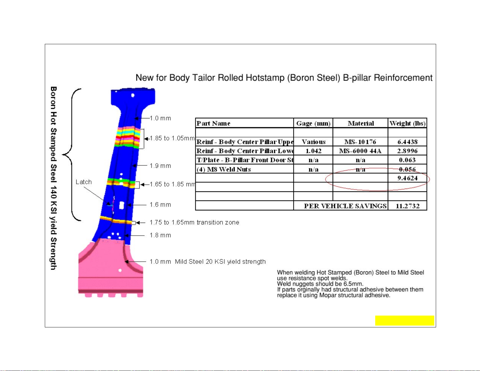
MS 10176 - Boron-alloyed steels ate analogy with 22MnB5 which are matched to the hardening process die. Sheet
blanks are heat treated in the furnace on an inert gas or air atmosphere and then formed in the press die and hardened at the same time. The boron is produced in two configurations one for use in upper body and one that has hotdip aluminizated coating for corrosion protection.
MS82-1228 - Represent a coated high strength low alloy (HSLA) hot or cold rolled sheet steel used in applictions where structural
integrity is critical.
PARTIAL LIST OF STEEL APPLICATIONS
Galvannealed Steel
Body Side Aperture Rear Door - Inner Panel
Cowl Plenum Panel Rear Door - Outer Panel
Cowl Side Panel Rear Floor Pan
Dash Panel Rear Floor Pan Front Crossmember
Front Door - Inner Panel Rear Floor Pan Side Rail
Front Door - Outer Panel Rear Suspension Crossmember
Front Fender Rear Quarter Panel - Inner
Front Floor Pan Rear Quarter Panel - Outer
Front Hinge Pillar Rear Wheelhouse - Inner
Front Rail Roof Panel
Front Strut Mounting Tower UpperLoad Path Beam
Front Wheelhouse (Front and Rear) Upper Radiator Crossmember
Lower Radiator Crossmember
Back to Index
Page 6

BODY CONSTRUCTION CHARACTERISTICS
The following measures have been implemented in order to provide maximum corrosion prevention and protection.
1. The use of galvannealed coatings throughout the body structure.
2. Ecoat is used on the complete body in all instances.
3. Body sealing.
4. Stone-chipping resistant primer application.
5. Underbody corrosion prevention.
Back to Index
Page 7
Back to Index
Page 8
Back to Index
Page 9
Back to Index
Page 10

Back to Index
Page 11

HISTORY OF COLLISION REPAIR
Time was, if you had an accident, the call went out to the insurance company - to the collision shop - or several shops get the lowest bid and in no time at all, the vehicle was repaired.
The facilities, training, and equipment were simple. Use a torch to cut, shape, and bend. Use something substantial as
an anchoring point - maybe a tree and then just pull.
Use plenty of solder or body putty to make it look good. With the frame and body vehicle, the job was easy; first
straighten the frame - then fix the mechanical components and the body work was cosmetic. This was all well and good
until the mid - '70s.
Then, the designers, engineers, and manufacturers had to find ways to make the vehicles energy efficient - and that
meant unibody cars. The unibody concept wasn't new - back in the '30s the Chrysler Air Flow had it - race cars have it and now the driving public worldwide has it.
The change came quickly. Manufacturers devoted time, money, and talent to develop the unibody car.
The public was ready to buy and did!
But then came the problem! The collision repair industry wasn't given the luxury of taking their time to train people in the
new technology - or take time to plan for new equipment.
The collision happened and the vehicle had to be fixed. Cars that were repairable were being totalled.
Cars that were repaired were not repaired correctly. Everybody was in a quandary - auto manufacturer - insurance
company - repair equipment people - body shops - and repair technicians.
The problem started in the early '70s and body shops are still catching up today. Yesterday's "ding" is today's "crash". It
takes trained technicians and sophisticated equipment to do the repair today.
That's why DaimlerChrysler is taking the time and effort to get the right information into the hands of the people that
handle the repair job.
Back to Index
Page 12
Corrosion Protection
Factory Applied Corrosion Protection
During the manufacturing of the unibody car, the manufacturer applies "corrosion protection" using specialized
manufacturing processes. This system is not duplicated in the collision repair body shop. However, the body shop still
has a responsibility to apply corrosion protection to the unibody vehicle. So, the collision repair shop must use
alternative materials to do the corrosion protection job after the repair.
This corrosion protection is required regardless of the environment and weather conditions the vehicle will be operated
in. Corrosion protection is as important in the desert as it is at the seaside. Corrosion damage can literally destroy the
structural integrity of a unibody vehicle from within. Many corrosion protection systems are destroyed during collision
repair operations. Metal finishing, metal working and fatigue can cause the breakdown of many of the corrosion barriers
installed at the factory. The use of heat for stress relief and welding also destroys factory installed corrosion barriers.
These corrosion barriers and corrosion protection systems must be replaced after collision repair to ensure that the
structural integrity of the unibody will remain intact throughout its life. In the past, only vehicles with aftermarket or after
delivery corrosion protection systems installed were serviced after collision repair to restore the corrosion protection
system.
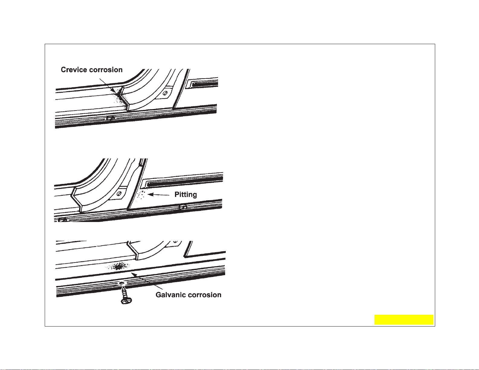
An understanding of the types of corrosion which affect the unibody vehicles will assist in understanding why the factory
protection systems are important, how the factory protection systems consist of and how the systems' protection is
replaced after collision and electrolytic corrosion. Some of the more common types of corrosion are crevice corrosion,
pitting, galvanic corrosion, stress corrosion, cracking, fretting, and erosion corrosion.
Back to Index
Page 13
Corrosion Protection
Crevice corrosion is a form of localized attack that occurs in areas on metal surfaces exposed to the elements.
Examples include spot weld lap joints, threaded or riveted connections, gasket fittings, porous welds, valve seats.
Pitting is the corrosion of a metal surface at points or small areas which look like a small hole in the metal.
Galvanic corrosion is the type that occurs when dissimilar metals are in electrical contact while immersed in an
electrolyte.
Back to Index
Page 14

Corrosion Protection
The penetration of corrosive solutions into these small areas, with widths that are typically a few thousandths of an inch,
can result in various types of failures: the metal surface may become rusty in appearance, operating components may seize
when protective coatings may have been removed from the metal surface. The coating of zinc on steel, known as galvanized, is an example of sacrificial cathodic protection.
An example of galvanic corrosion on the automobile is a stainless steel trim molding on a painted mild steel. When the paint
becomes damaged, a galvanic corrosion cell is formed between the passive stainless steel (cathode) and the steel (anode).
The corrosion leads to what would look like a rust stain. Methods of reducing galvanic corrosion include the use of
compatible materials, minimizing of cathode-to-anode areas, the insulation of dissimilar metal contacts and the use of thick,
replaceable sections.
Stress corrosion, cracking, fretting, and erosion corrosion.
Corrosion cracking is the early cracking of metals produced by the combined action of tensile stress and a corrosive
atmosphere.
Corrosion fatigue is cracking due to the action of stresses and corrosion. Methods of reducing corrosion fatigue include the
reduction in stress and the use of coatings.
Fretting is the deterioration of a metal at contact surfaces due to the presence of a corrosive and relative motion between
the surfaces. The two metal surfaces initially are covered with an oxide film that becomes abraded during vibration. The
results are oxide particles that become corroded. During the collision repair process, the factory protection materials
become damaged from working the metals, or from the use of heat in the repair operations. If these factory protection materials are not replaced with some similar protection material after repair, a corrosion hot spot is formed. A corrosion hot spot
is a small unprotected area surrounded by a protected area throughout the rest of the vehicle. the hot spot effect causes
rapid deterioration of the unprotected area. This deterioration takes place at a much faster rate, sometimes 10-12 times
faster than if the entire car were unprotected. The hot spot effect is created because all the corrosive factors are channeled
to the unprotected area much the same way all material flowing through a funnel is concentrated in a small area. This hot
spot effect means that corrosion failures to the unibody structure could occur in a short period of time even in an
atmosphere normally not subject to corrosion. The hot spot effect can cause rapid deterioration of unibody structures from
corrosion damage in a desert as well as seaside.
Back to Index
Page 15

Corrosion Protection
The types of materials used in rustproofing application include oil based materials, wax base materials, primers and
color coats. The most important properties of rustproofing materials are adhesion, toughness, and the resistance to the
environment. The best coating in the world is not effective unless it is present in the right place at the right time.
Corrosion Protection Information
When making the collision repair, refer to the manufacturer's information on where corrosion protection and sealants
are applied. Be sure to follow the recommendations. The application process is usually included with the material
manufacturer's information so be sure to read and understand it before proceeding with the repair.
Collision Repair Corrosion Protection Materials
The materials must provide good electrolyte barriers. The material must also be able to penetrate tiny crevices and
prevent abrasive corrosion. The material must be compatible with paint systems as many areas of the car must be
treated before paint is applied.
Materials containing silicones will cause paint conditions such as fish eyes if they are applied before the repaired
vehicle is painted. So no silicone containing material is to be used. As many of the repair areas are more accessible
before final assembly and painting, the non-silicone type materials are a must for this type of application.
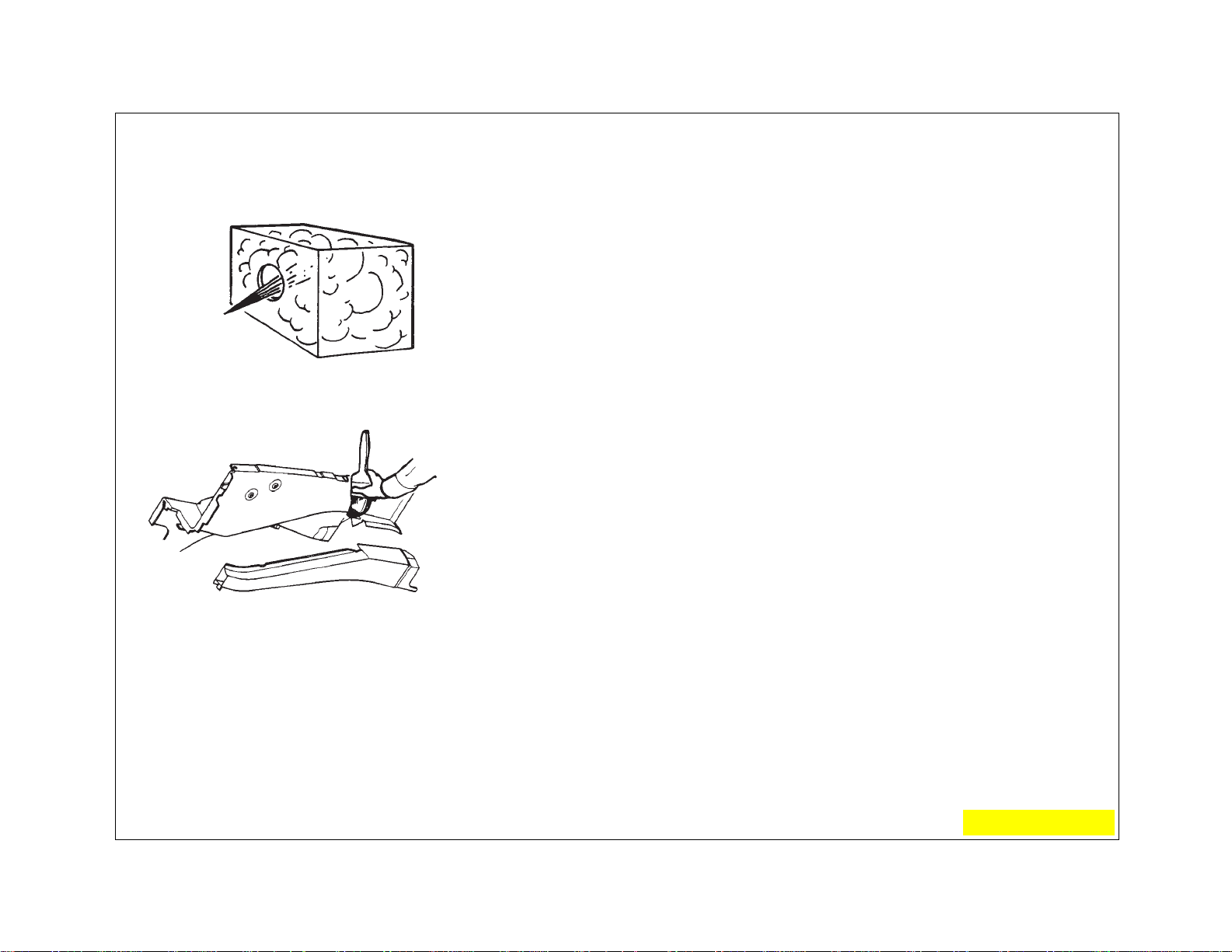
When protecting an enclosed area, fog type properties for the corrosion protection material are a plus. The fog
properties make the material much less susceptible to operator error or misapplication. With a fog type material, once
the material is introduced inside of an enclosure, the fog spreads rapidly and evenly into all areas including tiny
crevices. The fog type materials do not require direct spray application to be effective. Fog type materials are also very
effective in coating over any existing rusted or corrosion damaged areas and preventing further corrosion of these
areas. This is especially important on repairs of older vehicles.
Back to Index
Page 16
Corrosion Protection
Spray Accessibility to the Repair
Being able to achieve fog spray penetration into enclosed cavities as well as open areas requires application
equipment, which includes an assortment of wands of various lengths and design.
Some areas are more effectively treated by brush application of corrosion protection material before they are
assembled. A good example of this is an inner and outer engine compartment side rail area. Brush application to the
inside of these areas as individual pieces is easy before assembly and can be followed by a light fog application to the
weld areas and the crevices formed during assembly after the rails are assembled. Brush application keeps the foreign
material from getting between welded joints during assembly yet gives good coverage to general areas with easy
application. The material selected in addition to paint compatibility features and fog application features is also an
excellent brush application material. Repaired areas, boxed in or closed in are more easily treated during assembly
using fog and brush on techniques. Care must be taken to keep the corrosion materials away from the welding areas
as welding contamination might take place. Brush-on applications are used before welding and fog in applications are
used after welding assemblies together.
Back to Index
Page 17

Back to Index
Corrosion Protection
Desired Characteristics of Corrosion Protection Material
1. Corrosion prevention material- The material must displace water to prevent corrosion. This can be tested by
spraying water on an open panel on the floor, then spraying the corrosion preventative material over the watered panel
and observing if the material displaces the water.
2. Creepage of material- To insure thorough and complete protection coverage, the material should have a "creep"
capability, approximately 1/4 inch per minute while drying. This assures protective penetration of pinch welds, cracks, etc.
3. Safe material- Material should be non-combustible when dried and when wet unable to support a fire after ignition.
4. Clean-up- The material should be of a viscosity which inhibits runs or drips. Overspray on a vehicle's painted surface
should wipe off easily without solvent when wet, with solvent when dry. The material should also dry clean off clothing.
5. Guarantee/Warranty- The corrosion protection has to be done to maintain factory corrosion warranty.
Manufacturer's recommendations must be followed.
Glossary:
Abrasion Corrosion - Rubbing or hitting of one material by another
Corrosion Protection - Material applied to deter corrosion (oxidation)
Crevice Corrosion - Oxidation when two metals are joined
Electrolytic Corrosion - Electrical action taking place between two materials in the presence of an electrolyte (liquid)
Fogging - Applying material in a mist form
Fretting - Deterioration of metal at contact surfaces due to motion and corrosive elements
Galvanic Corrosion - Electrical action (electrolysis) between two dissimilar metals in the presence of electrolyte (liquid)
Hot Spot - An unprotected area subject to corrosion
Pitting Corrosion - Corrosion on a surface the results in a small "specks" or "pinholes"
Stress of Fatigue, Cracking Corrosion - Cracking due to stress and atmospheric elements
Page 18
Back to Index
Page 19
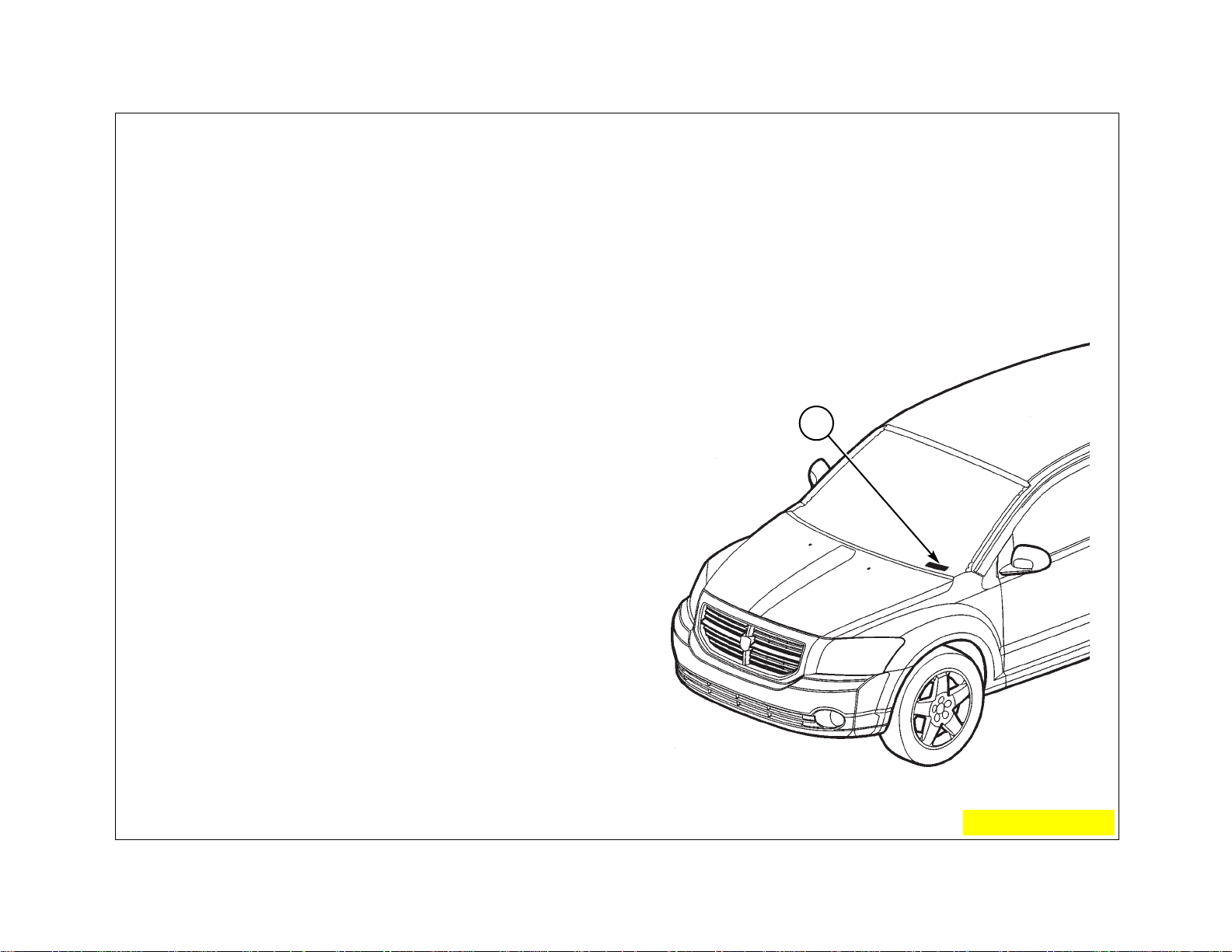
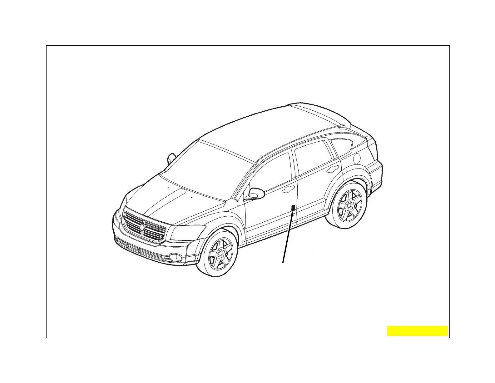
DODGE CALIBER VEHICLE IDENTIFICATION NUMBER DESCRIPTION
The Vehicle Identification Number (VIN) can be viewed through the windshield at the upper left corner of the instrument
panel, near the left windshield pillar. The VIN consists of 17 characters in a combination of letters and numbers that
provide specific information about the vehicle. Refer to VIN Code Breakdown Chart for decoding information. To protect
the consumer from theft and possible fraud the manufacturer is required to include a Check Digit at the ninth position of
the vehicle identification number. The check digit is used by the manufacturer and government agencies to verify the
authenticity of the vehicle and official documentation. The formula to use the check digit is not released to the general
public.
VEHICLE IDENTIFICATION NUMBER (VIN)
1 - VEHICLE IDENTIFICATION NUMBER (VIN)
1
Back to Index
Page 20
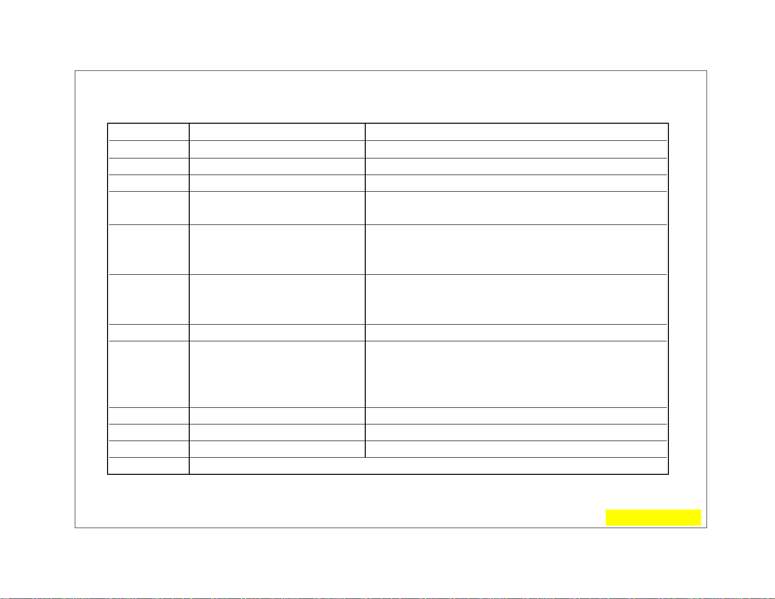
VEHICLE IDENTIFICATION NUMBER DECODING CHART
POSITION INTERPRETATION CODE = DESCRIPTION
1 Country of Origin 1 = Manufactured by Daimler Chrysler Corporation
2 Make B = Dodge
3 Vehicle Type 3 = Passenger Car
4 Restraint System J = Without Side Air Bags
H = With Side Air Bags
5 Vehicle Line (PM) 3 = Caliber Right Hand Drive (FWD)
B = Caliber Left Hand Drive (FWD)
E = Caliber Left Hand Drive (AWD)
6 Series 2 = Caliber
4 = Caliber SXT
7 = Caliber R/T
7 Body Style 8 = Hatchback 4 Door
8 Engine C = 1.8L 4 Cyl. 16V DOHC Dual VVT GAsoline
A = 2.0L 4 Cyl. 16V DOHC Diesel
B = 2.0L 4 Cyl. 16V DOHC 5MPI Gasoline
K = 2.4L 4 Cyl. 16V Dual VVT Gasoline
9 Check Digit 0 through 9 or X
10 Model Year 7 = 2007
11 Assembly Plant D = Belvidere Assembly
12 through 17 Vehicle Build Sequence
Back to Index
Page 21
MFD BY
DAIMLER CHRYSLER
CORPORATION
DATE OF MFR GVWR
1-96 C 2268 KG (05000 LB)
GAWR FRONT
1203 KG (2850 LB)
GAWR REAR
1225 KG (2700 LB)
WITH TIRES
P185/75R14
WITH TIRES
P195/75R14
RIMS AT
14 X 5.5
RIMS AT
14 X 5.5
COLD
380 KPA(35 PSI)
COLD
380 KPA(35 PSI)
THIS VEHICLE CONFORMS TO ALL APPLICABLE FEDERAL MOTOR VEHICLE SAFETY
STANDARDS IN EFFECT ON THE DATE OF MANUFACTURE SHOWN ABOVE.
VIN: XXXXXXXXXXXXXXXXX TYPE: SINGLE X DUAL
MDH:
010615 021
PAINT:POP VEHICLE MADE IN CANADA TRIM:
C503
4848505
8086df7b
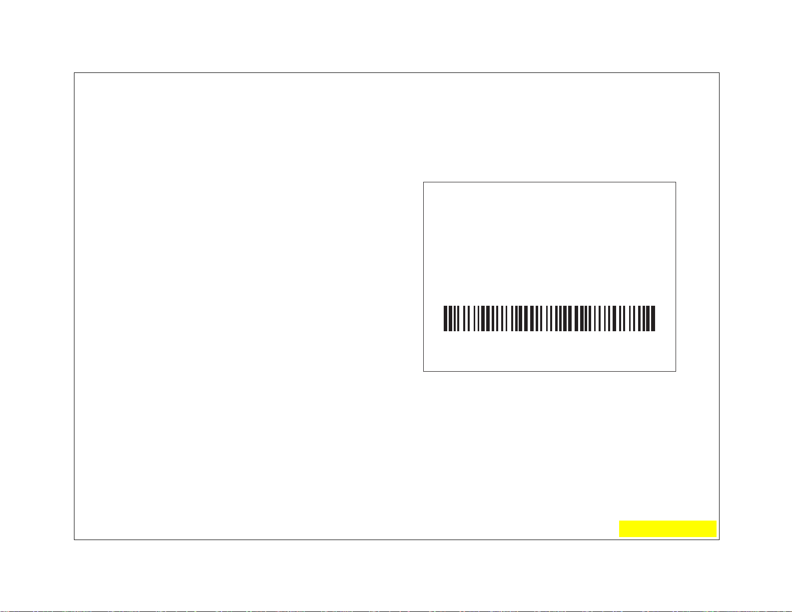
VEHICLE CERTIFICATION LABEL
DESCRIPTION
A vehicle certification label is attached to every
DaimlerChrysler Corporation vehicle. The label certifies
that the vehicle conforms to all applicable Federal
Motor Vehicle Standards. The label also lists:
• Month and year of vehicle manufacture.
• Gross Vehicle Weight Rating (GVWR). The gross
front and rear axle weight ratings (GAWR’s) are
based on a minimum rim size and maximum cold
tire inflation pressure.
• Vehicle Identification Number (VIN).
• Type of vehicle.
• Type of rear wheels.
• Bar code.
• Month, Day and Hour (MDH) of final assembly.
• Paint and Trim codes.
• Country of origin.
The label is located on the driver-side door shut-face.
Back to Index
Page 22
DODGE CALIBER PAINT CODES
EXTERIOR
CODE COLOR
ARH Inferno Red Crystal Pearl Coat
VYH Solar Yellow Clear Coat
DV6 Sunburst Orange Pearl Coat
CB6 Marine Blue Pearl Coat
DBM Steel Blue Metallic Pearl Coat
WS2 Bright Silver Metallic Clear Coat
DX8 Black Clear Coat
SW1 Stone White Clear Coat
INTERIOR
CODE COLOR
S Pastel Slate Gray (DA)
B Pastel Pebble Beidge/Medium Pebble Beidge (KA)
Back to Index
Page 23
Back to Index
DODGE CALIBER PAINT CODE LOCATION
The vehicle certification label identifies the paint code. This label is located on the driver’s door shut face.
VEHICLE
CERTIFICATION
LABEL
Page 24
Back to Index
Page 25
WELD PANEL
REPLACEMENT
Dodge Caliber
The basic parts of the body structure are the welded panels. This section contains a brief description of the placement
of some of the panels and their weld locations.
Note: To ensure the strongest, most durable and cleanest welds possible, perform testing before and during all weld
procedures. Always follow American Weld Society specifications and procedures.
Note: Diagrams do not show all of the parts.
Explanation of Manual Contents......................................... Liftgate...................................................................................
Front Floor ........................................................................... Engine Box Assembly ...........................................................
Sidemember........................................................................ Plenum/Dash.........................................................................
Rear Floor ........................................................................... Engine Box Complete............................................................
Front Rails........................................................................... Front Floor Complete ............................................................
Plenum................................................................................ Rear Floor Complete.............................................................
Dash.................................................................................... Underbody Complete.............................................................
Engine Box.......................................................................... Body Side Aperture Inner......................................................
Body Side Aperture............................................................. Body Side Aperture Outer .....................................................
Hood and Front Fenders..................................................... Body Side Aperture Complete...............................................
Front Door........................................................................... Roof without Sunroof.............................................................
Rear Door ............................................................................ Body in White Complete ...........................
Back to Index
Page 26
Explanation of Welding/Sealer Information
The major construction of a unibody vehicle consists of welded panels that create the supporting structure for all components and assemblies of the vehicle. Here are some examples for replacement of these parts.
Certain body components must use sealers to ensure proper assembly. Be sure to check the Body Sealing
Locations and Structural Adhesive Sections for location and sealer type.
Back to Index
Page 27

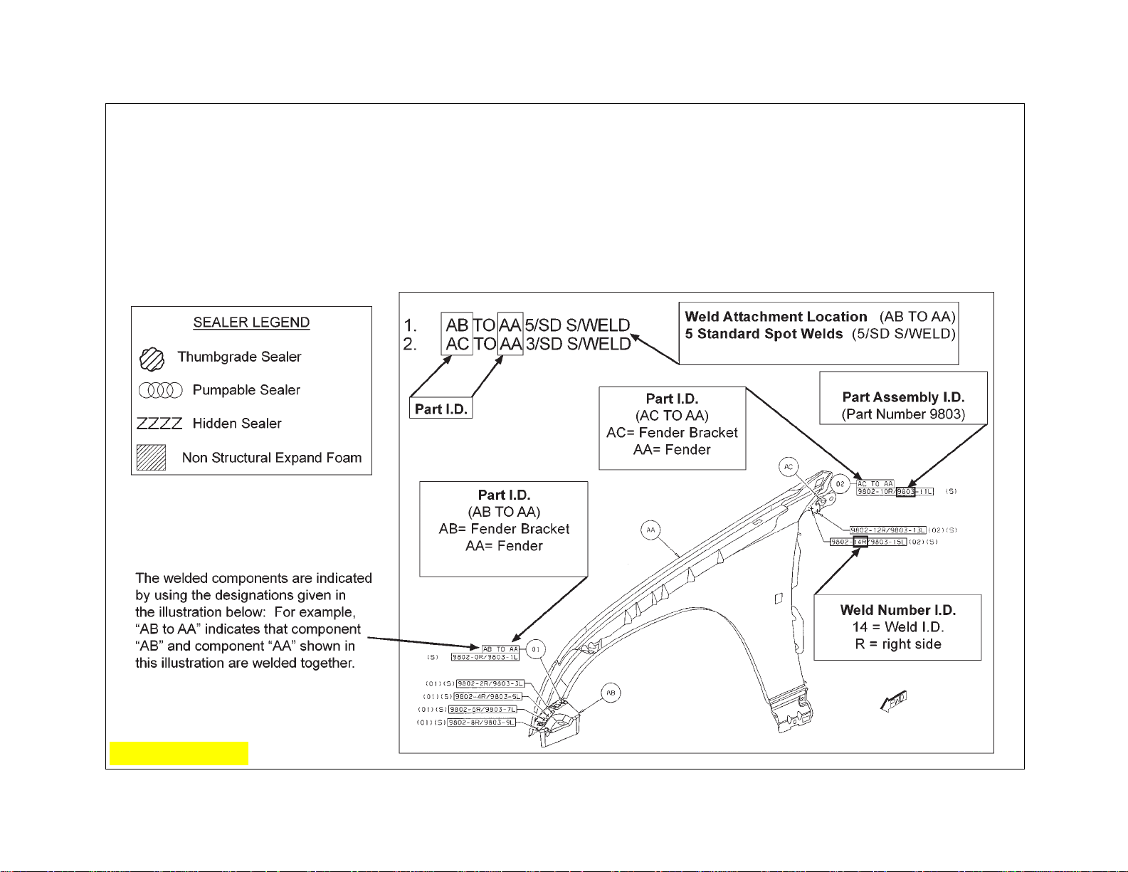
Explanation of Welding Abbreviations
Definitions
Weld Type
(ORD)=Ordinary Weld or Standard
(CRT)=Critical Weld or Diamond
(SAF)=Safety Weld
PROJ=Projection Weld
FCAW=Flex Core Arc Weld
MFG=Manufacturing Weld
S/WELD=Spot Welds
/SD=Per Side
Examples
AA TO AB 5/SD S/WELDS (ORD)=
PART AA WELDED TO PART AB 5 PER SIDE (5 RIGHT/5 LEFT) SPOT WELDS STANDARD
AA TO AB 12 PROJ WELDS (CRT)=
PART AA WELDED TO PART AB 12 PROJECTION WELDS CRITICAL OR DIAMOND
Adhesives
STRUCT ADH (ORD) = Ordinary Structural Adhesive
ADH (ORD) = Ordinary Adhesive
Back to Index
Page 28
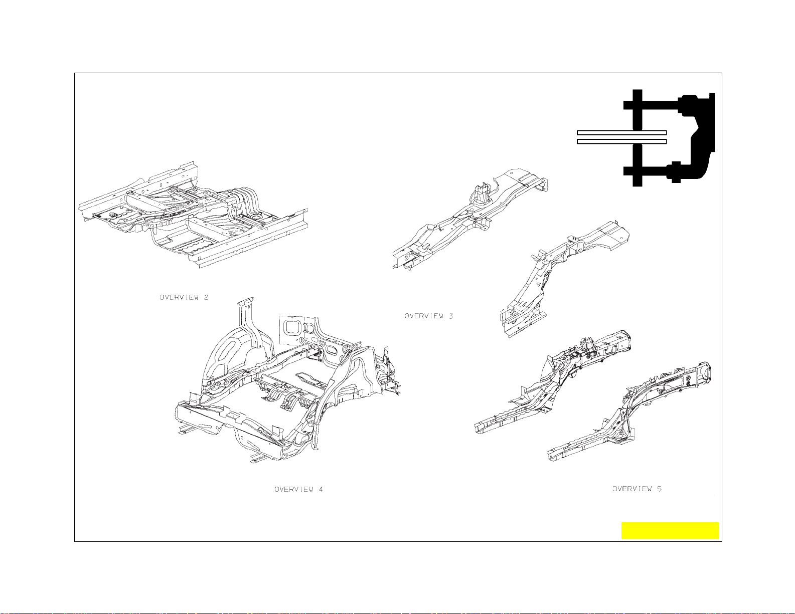
WELD LOCATION OVERVIEW ZONES
Back to Index
Page 29
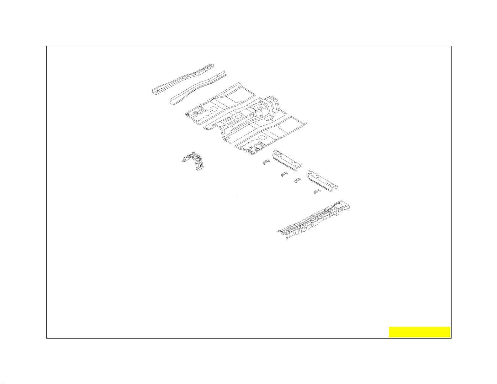
DODGE CALIBER FRONT FLOOR SECTION
AA REINF – TUNNEL –
AB REINF – HAND BRAKE MTG –
AC CROSSMEMBER – FRT FLOOR PAN FRT RT –
AC CROSSMEMBER – FRT FLOOR PAN FRT LT –
AD 05115421
AE CROSSMEMBER – TUNNEL FRT –
AF NUT/WELD.HEX – NIBS.NO.FIN. – DRIVE
SHAFT TO CROSSMEMBER
AG HOOK – MUFLER HANGER BRACKET –
AH BRACKET – CONSOLE –
AJ NUT/WELD.HEX – NIBS.NO.FIN.PILET.PT –
ESP MODULE TO TUNNEL REINF
AK STUD.WELD/INTERNAL – HEADER.PT.NIBS.NO.
FIN – PARK BRAKE LEVER TO TUNNEL REINF
AL NUT/WELD.HEX – NIB.NO.FIN.PILET. PT – FUEL
TUBE TO RAIL EXT
AM STUD.WELD/EXTERNAL – HEADER.PT.PNT.
CUTTER.SPECIAL – WIRING TO SILL INR RT
AM STUD.WELD/EXTERNAL – HEADER.PT.PNT.
CUTTER.SPECIAL – WIRING TO SILL INR LT
AN SILL – FRT FLOOR –
AN SILL – FRT FLOOR –
AP RAIL – TUNNEL FRT RT –
AP RAIL – TUNNEL FRT LT –
Back to Index
Page 30
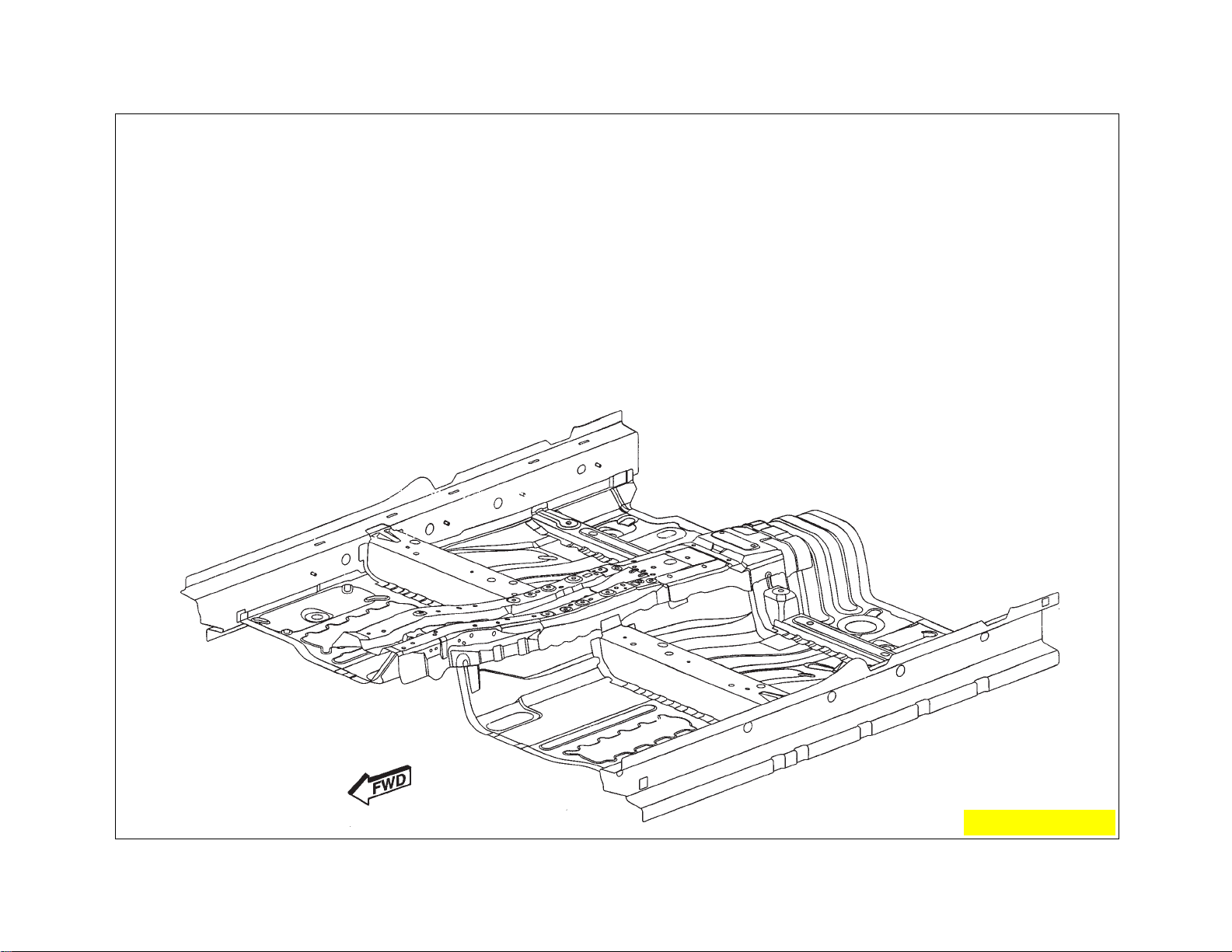
PARTS IDENTIFICATION LEGEND, OVERVIEW 2
Back to Index
AA REINF – TUNNEL –
AB REINF – HAND BRAKE MTG –
AC CROSSMEMBER – FRT FLOOR PAN FRT RT –
AC CROSSMEMBER – FRT FLOOR PAN FRT LT –
AD 05115421
AE CROSSMEMBER – TUNNEL FRT –
AF NUT/WELD.HEX – NIBS.NO.FIN. – DRIVE
SHAFT TO CROSSMEMBER
AG HOOK – MUFLER HANGER BRACKET –
AH BRACKET – CONSOLE –
AJ NUT/WELD.HEX – NIBS.NO.FIN.PILET.PT –
ESP MODULE TO TUNNEL REINF
AK STUD.WELD/INTERNAL – HEADER.PT.NIBS.NO.
FIN – PARK BRAKE LEVER TO TUNNEL REINF
AL NUT/WELD.HEX – NIB.NO.FIN.PILET. PT – FUEL
TUBE TO RAIL EXT
AM STUD.WELD/EXTERNAL – HEADER.PT.PNT.
CUTTER.SPECIAL – WIRING TO SILL INR RT
AM STUD.WELD/EXTERNAL – HEADER.PT.PNT.
CUTTER.SPECIAL – WIRING TO SILL INR LT
AN SILL – FRT FLOOR –
AN SILL – FRT FLOOR –
AP RAIL – TUNNEL FRT RT –
AP RAIL – TUNNEL FRT LT –
Page 31

WELD LAYOUT LOCATION GUIDE
Back to Index
Page 32

01 AB TO AA 10 S/WELDS (ORD)
Back to Index
Page 33

02 AD TO AC 24 S/WELDS (ORD)
03 AF TO AE 1 PROJ WELD (ORD)
04 AG TO AE 2 ARC WELDS (ORD)
Back to Index
Page 34

05 AH TO AA 13 S/WELDS (ORD)
06 AJ TO AA 4 PROJ WELDS (ORD)
07 AL TO AA 2 PROJ WELDS (ORD)
08 AK TO AB 2 PROJ WELDS (ORD)
Back to Index
Page 35

09 AM TO AN 8 PROJ WELDS (ORD)
10 AF TO AD 1 PROJ WELD (ORD)
Back to Index
Page 36

11 AR TO AP 8/SD S/WELDS (ORD)
12 AS TO AP 2 S/WELDS (ORD)
13 AT TO TP 1 PROJ WELD (ORD)
Back to Index
Page 37

DODGE CALIBER SIDEMEMBER SECTION
AA SIDEMEMBER – RR FLOOR UPR RT –
AA SIDEMEMBER – RR FLOOR UPR LT –
AB EXTENSION – RR FLOOR PAN RT –
AB EXTENSION – RR FLOOR PAN LT –
AC SIDEMEMBER – RR FLOOR LWR RT –
AC SIDEMEMBER – RR FLOOR LWR LT–
AD 05115200AA/05115201AA – EXTENSION – RR
FLOOR SIDEMEMBER – RT/LT
AE SILL – RR FLOOR SIDEMEMBER RT –
AE SILL – RR FLOOR SIDEMEMBER LT –
AF REINF – RR SPRING –
AF REINF – RR SPRING –
AG BRACKET – RR SPRING –
AG BRACKET – RR SPRING –
AH PANEL – RR SPRING –
AH PANEL – RR SPRING –
AJ 05115204AA/05115205AA – SUPPORT ASSY –
RR BUMPER RT/LT
AK EXTENSION – RR FLOOR CROSSMEMBER
FRT RT –
AK EXTENSION – RR FLOOR CROSSMEMBER
FRT LT –
AL BRACKET – TRAILING ARM RT –
AL BRACKET – TRAILING ARM LT –
AM BULKHEAD – RR FLOOR SIDEMEMBER RT –
AM BULKHEAD – RR FLOOR SIDEMEMBER LT –
AN EXTENSION – RR FLOOR SIDEMEMBER RT –
AN EXTENSION – RR FLOOR SIDEMEMBER LT –
AP REINF – RR FLOOR SIDEMEMBER EXTENSION
RT –
AP REINF – RR FLOOR SIDEMEMBER EXTENSION
LT –
AR BULKHEAD – RR FLOOR SIDEMEMBER
EXTENSION RT –
AR BULKHEAD – RR FLOOR SIDEMEMBER
EXTENSION LT –
Back to Index
AS REINF – MUFFLER HANGER BRACKET –
AT BRACKET – PARKING BRAKE CABLE RR RT –
AT BRACKET – PARKING BRAKE CABLE RR LT –
AU BRACKET – RR BRAKE HOSE –
AU BRACKET – RR BRAKE HOSE –
AV BULKHEAD – RR FLOOR SIDEMEMBER RT –
CENTER
AV BULKHEAD – RR FLOOR SIDEMEMBER LT –
CENTER
AW BRACKET – RR SUSPENSION FRT –
AX BRACKET – RR SUSPENSION RR RT –
AX BRACKET – RR SUSPENSION RR LT –
AY REINF – RR FLOOR SIDEMEMBER RT –
AY REINF – RR FLOOR SIDEMEMBER LT –
AZ BULKHEAD – RR FLOOR SIDEMEMBER RT –
AZ BULKHEAD – RR FLOOR SIDEMEMBER LT –
BA NUT– PIPE – RR SUSPENSION TO BODY
BA NUT– PIPE – RR SUSPENSION TO BODY
Page 38

PARTS IDENTIFICATION LEGEND, OVERVIEW 3
Back to Index
AA SIDEMEMBER – RR FLOOR UPR RT –
AA SIDEMEMBER – RR FLOOR UPR LT –
AB EXTENSION – RR FLOOR PAN RT –
AB EXTENSION – RR FLOOR PAN LT –
AC SIDEMEMBER – RR FLOOR LWR RT –
AC SIDEMEMBER – RR FLOOR LWR LT–
AD 05115200AA/05115201AA – EXTENSION – RR
FLOOR SIDEMEMBER – RT/LT
AE SILL – RR FLOOR SIDEMEMBER RT –
AE SILL – RR FLOOR SIDEMEMBER LT –
AF REINF – RR SPRING –
AF REINF – RR SPRING –
AG BRACKET – RR SPRING –
AG BRACKET – RR SPRING –
AH PANEL – RR SPRING –
AH PANEL – RR SPRING –
AJ 05115204AA/05115205AA – SUPPORT ASSY –
RR BUMPER RT/LT
AK EXTENSION – RR FLOOR CROSSMEMBER
FRT RT –
AK EXTENSION – RR FLOOR CROSSMEMBER
FRT LT –
AL BRACKET – TRAILING ARM RT –
AL BRACKET – TRAILING ARM LT –
AM BULKHEAD – RR FLOOR SIDEMEMBER RT –
AM BULKHEAD – RR FLOOR SIDEMEMBER LT –
AN EXTENSION – RR FLOOR SIDEMEMBER RT –
AN EXTENSION – RR FLOOR SIDEMEMBER LT –
AP REINF – RR FLOOR SIDEMEMBER EXTENSION
RT –
AP REINF – RR FLOOR SIDEMEMBER EXTENSION
LT –
AR BULKHEAD – RR FLOOR SIDEMEMBER
EXTENSION RT –
AR BULKHEAD – RR FLOOR SIDEMEMBER
EXTENSION LT –
AS REINF – MUFFLER HANGER BRACKET –
AT BRACKET – PARKING BRAKE CABLE RR RT –
AT BRACKET – PARKING BRAKE CABLE RR LT –
AU BRACKET – RR BRAKE HOSE –
AU BRACKET – RR BRAKE HOSE –
AV BULKHEAD – RR FLOOR SIDEMEMBER RT –
CENTER
AV BULKHEAD – RR FLOOR SIDEMEMBER LT –
CENTER
AW BRACKET – RR SUSPENSION FRT –
AX BRACKET – RR SUSPENSION RR RT –
AX BRACKET – RR SUSPENSION RR LT –
AY REINF – RR FLOOR SIDEMEMBER RT –
AY REINF – RR FLOOR SIDEMEMBER LT –
AZ BULKHEAD – RR FLOOR SIDEMEMBER RT –
AZ BULKHEAD – RR FLOOR SIDEMEMBER LT –
BA NUT– PIPE – RR SUSPENSION TO BODY
BA NUT– PIPE – RR SUSPENSION TO BODY
Page 39

WELD LAYOUT LOCATION GUIDE
Back to Index
Page 40

01 AH TO AG 5/SD S/WELD (CRT)
02 AH TO AF 2/SD S/WELD (CRT)
03 AH TO AG TO AF 2/SD S/WELD (CRT)
04 AG TO AF 2/SD S/WELD (ORD)
05 AJ TO AD 6 S/WELD (ORD)
06 AF TO AD 9 SD S/WELD (ORD)
Back to Index
Page 41

07 AP TO AD 7/SD S/WELD (ORD)
08 AR TO AJ TO AD 6 S/WELD (CRT)
09 AS TO AD 4 S/WELD (ORD)
10 AE TO AC 12/SD S/WELD (ORD)
Back to Index
Page 42

11 AT TO AC 1 S/WELD (ORD)
12 AL TO AC 12 S/WELD (ORD)
13 AU TO AC 1 S/WELD (ORD)
14 AT TO AL TO AC 1 S/WELD (ORD)
15 AU TO AL TO AC 1 S/WELD (ORD)
16 AC TO AG 7/SD S/WELD (CRT)
Back to Index
Page 43

17 AV TO AC 2 S/WELD (ORD)
18 AW TO AC 13 S/WELD (CRT)
Back to Index
Page 44

19 AK TO AC 6R S/WELD (ORD)
20 AZ TO AC 3R S/WELD (ORD)
21 AX TO AG TO AC 2R S/WELD (CRT)
22 AX TO AC 5R S/WELD (CRT)
23 AZ TO AC TO AG 3R S/WELD (CRT)
Back to Index
Page 45

24 AY TO AC 5R S/WELD (CRT)
25 AY TO AL 2R S/WELD (CRT)
26 AY TO AE TO AC 2R S/WELD (CRT)
27 AN TO AC 10R S/WELD (ORD)
Back to Index
Page 46

28 AK TO AC TO AR 2R S/WELD (ORD)
29 AY TO AC TO AA 13R S/WELD (CRT)
30 AM TO AE 3R S/WELD (ORD)
31 AY TO AE TO AA 6R S/WELD (CRT)
32 AE TO AC TO AA 1R S/WELD (ORD)
33 AD TO AC 10R S/WELD (ORD)
Back to Index
Page 47

34 AD TO AA 11R S/WELD (ORD)
35 AD TO AC TO AA 4R S/WELD (CRT)
36 AC TO AA 5R S/WELD (ORD)
37 AC TO AA 1R S/WELD (CRT)
38 AY TO AC TO AA 6R S/WELD (CRT)
Back to Index
Page 48

39 AD TO AB 7R S/WELD (ORD)
40 AD TO AB TO AA 2R S/WELD (ORD)
41 AG TO AA 2R S/WELD (CRT)
42 AG TO AF TO AC 2R S/WELD (CRT)
43 AG TO AC TO AA 2R S/WELD (CRT)
44 AH TO AG TO AA 2R S/WELD (CRT)
45 AB TO AA 4R S/WELD (ORD)
Back to Index
Page 49

46 AJ TO AD 6L S/WELD (ORD)
47 AP TO AD 6L S/WELD (ORD)
48 AD TO AA 11L S/WELD (ORD)
49 AR TO AJ TO AD 6L S/WELD (CRT)
Back to Index
Page 50

50 AL TO AC 13L S/WELD (CRT)
51 AU TO AC 1L S/WELD (CRT)
52 AU TO AC TO AL 1L S/WELD (CRT)
53 AT TO AC 2L S/WELD (CRT)
54 AV TO AC TO AK 4L S/WELD (ORD)
55 AV TO AC 2L S/WELD (ORD)
Back to Index
Page 51

56 AK TO AC 2L S/WELD (ORD)
57 AG TO AF TO AC 2L S/WELD (CRT)
58 AZ TO AC TO AG 3L S/WELD (CRT)
59 AZ TO AC 3L S/WELD (ORD)
60 AD TO AC 6L S/WELD (ORD)
Back to Index
Page 52

61 AY TO AC 5L S/WELD (CRT)
62 AY TO AL 2L S/WELD (CRT)
63 AN TO AC 9L S/WELD (ORD)
64 AX TO AC 5L S/WELD (CRT)
65 AX TO AG TO AC 2L S/WELD (CRT)
66 AM TO AE 1L S/WELD (ORD)
Back to Index
Page 53

67 AD TO AC TO AA 4L S/WELD (CRT)
68 AK TO AC TO AA 2L S/WELD (ORD)
69 AY TO AC TO AA 19L S/WELD (CRT)
Back to Index
Page 54

70 AB TO AA 4L S/WELD (ORD)
71 AY TO AE TO AC 2L S/WELD (CRT)
72 AE TO AC TO AA 1L S/WELD (CRT)
73 AY TO AE TO AA 6L S/WELD (CRT)
74 AD TO AB 7L S/WELD (ORD)
75 AD TO AB TO AA 2L S/WELD (ORD)
Back to Index
Page 55

76 AG TO AA 4L S/WELD (CRT)
77 AH TO AG TO AA 2L S/WELD (CRT)
78 AG TO AC TO AA 2L S/WELD (CRT)
79 AC TO AA 5L S/WELD (CRT)
Back to Index
Page 56

80 AE TO AC 1/SD FCAW (ORD)
81 AY TO AE 1/SD ADH BESAD (ORD)
82 AX TO AC 1/SD FCAW (CRT)
83 AX TO AC 1/SD FCAW (CRT)
84 BA TO AX 2/SD FCAW (CRT)
Back to Index
Page 57

85 AG TO AC TO AA 1/SD ADH BEAD 9ORD)
86 AB TO AA 1/SD ADH BEAD (ORD)
87 AY TO AE TO AA 1/SD ADH BEAD (ORD)
Back to Index
Page 58

88 BA TO AC 1/SD FCAW (CRT)
89 BA TO AC 1/SD FCAW (CRT)
90 AG TO AF TO AC 1/SD ADH BEAD (ORD)
Back to Index
Page 59

BD REINF – SPARE TIRE HOLD-DOWN –
BE TAPPING PLATE –
BF EXTENSION – RR FLOOR –
BG BRACKET – RR FLOOR EXTENSION SIDE RT –
BG BRACKET – RR FLOOR EXTENSION SIDE LT –
BH BRACKET – RR FLOOR EXTENSION CTR RT –
BH BRACKET – RR FLOOR EXTENSION CTR LT –
BJ CROSSMEMBER – RR SEAT –
BK EXTENSION – SIDEMEMBER FRT FLOOR RT –
BK BULKHEAD – CROSSMEMBER RR SEAT LT –
BL STUD.WELD/INTERNAL – HEADER.PT.NIBS.NO.
FIN – BRAKE LINE TO RH WHEELHOUSE ASSY
BM BULKHEAD – CROSSMEMBER RR SEAT RT –
BN NUT/WELD.HEX – NIBS.NO.FIN – FUEL TANK
TO RR SEAT X-MBR –
BP REINF – RR CLOSURE – RR END REINF
BR PANEL – RR CLOSURE – RR END CLOSURE
BS REINF – LIFTGATE STRIKER –
AA SIDEMEMBER – RR FLOOR LWR RT –
AA SIDEMEMBER – RR FLOOR LWR LT –
AB NUT – PIPE
AC EXTENSION – RR FLOOR –
AC EXTENSION – RR FLOOR SIDEMEMBER LT
AD SUPPORT – RR BUMPER RT –
AD SUPPORT – RR BUMPER LT –
AE 06104968AA
AF
SPACER – RR FLOOR SIDEMEMBER EXTENSION –
AG REINF – RR FLOOR SIDEMEMBER RT –
AG REINF – RR FLOOR SIDEMEMBER LT –
AH STUD.WELD/INTERNAL – HEADER.PT.NIBS.
NO.FIN – RR SEAT TO RAIL COVER
AJ NUT WELD HEX – NIBS.NO.FIN – RR SEAT TO
RAIL COVER
AK NUT – PIPE – TRAILING ARM TO RAIL
AL BRACKET – TRAILING ARM RT –
AL BRACKET – TRAILING ARM LT –
AM BRACKET – PARKING BRAKE CABLE RR RT –
AM BRACKET – PARKING BRAKE CABLE RR LT –
AN NUT/WELD.HEX – NIBS.NO.FIN.PIOLT.PT –
AP PANEL – RR WHEELHOUSE INR RT –
AP PANEL – RR WHEELHOUSE INR LT –
AR REINF – RR WHEELHOUSE RT –
AR REINF – RR WHEELHOUSE LT –
AS BRACKET – FILLER –
AT PLATE – SIDE SILL RT –
AT PLATE – SIDE SILL LT –
AU CROSSMEMBER – RR FLOOR FRT –
AV BRACKET – FUEL TANK RR –
AW BRACKET – RR SEAT –
AX SHIELD – FUEL TANK –
AY BRACKET – RR BRAKE HOSE –
AZ BRACKET – RR SUSPENSION FRT –
BA REINF – RR SEAT BELT –
BB BULKHEAD – FRR FLOOR CROSSMEMBER
FRT RT –
BC CROSSMEMBER – RR FLOOR RR –
DODGE CALIBER REAR FLOOR SECTION
Back to Index
Page 60

PARTS IDENTIFICATION LEGEND, OVERVIEW 4
Back to Index
BC CROSSMEMBER – RR FLOOR RR –
BD REINF – SPARE TIRE HOLD-DOWN –
BE TAPPING PLATE –
BF EXTENSION – RR FLOOR –
BG BRACKET – RR FLOOR EXTENSION SIDE RT –
BG BRACKET – RR FLOOR EXTENSION SIDE LT –
BH BRACKET – RR FLOOR EXTENSION CTR RT –
BH BRACKET – RR FLOOR EXTENSION CTR LT –
BJ CROSSMEMBER – RR SEAT –
BK EXTENSION – SIDEMEMBER FRT FLOOR RT –
BK BULKHEAD – CROSSMEMBER RR SEAT LT –
BL STUD.WELD/INTERNAL – HEADER.PT.NIBS.NO.
FIN – BRAKE LINE TO RH WHEELHOUSE ASSY
BM BULKHEAD – CROSSMEMBER RR SEAT RT –
BN NUT/WELD.HEX – NIBS.NO.FIN – FUEL TANK
TO RR SEAT X-MBR –
BP REINF – RR CLOSURE – RR END REINF
BR PANEL – RR CLOSURE – RR END CLOSURE
BS REINF – LIFTGATE STRIKER –
AA SIDEMEMBER – RR FLOOR LWR RT –
AA SIDEMEMBER – RR FLOOR LWR LT –
AB NUT – PIPE
AC EXTENSION – RR FLOOR –
AC EXTENSION – RR FLOOR SIDEMEMBER LT
AD SUPPORT – RR BUMPER RT –
AD SUPPORT – RR BUMPER LT –
AE 06104968AA
AF
SPACER – RR FLOOR SIDEMEMBER EXTENSION –
AG REINF – RR FLOOR SIDEMEMBER RT –
AG REINF – RR FLOOR SIDEMEMBER LT –
AH STUD.WELD/INTERNAL – HEADER.PT.NIBS.
NO.FIN – RR SEAT TO RAIL COVER
AJ NUT WELD HEX – NIBS.NO.FIN – RR SEAT TO
RAIL COVER
AK NUT – PIPE – TRAILING ARM TO RAIL
AL BRACKET – TRAILING ARM RT –
AL BRACKET – TRAILING ARM LT –
AM BRACKET – PARKING BRAKE CABLE RR RT –
AM BRACKET – PARKING BRAKE CABLE RR LT –
AN NUT/WELD.HEX – NIBS.NO.FIN.PIOLT.PT –
AP PANEL – RR WHEELHOUSE INR RT –
AP PANEL – RR WHEELHOUSE INR LT –
AR REINF – RR WHEELHOUSE RT –
AR REINF – RR WHEELHOUSE LT –
AS BRACKET – FILLER –
AT PLATE – SIDE SILL RT –
AT PLATE – SIDE SILL LT –
AU CROSSMEMBER – RR FLOOR FRT –
AV BRACKET – FUEL TANK RR –
AW BRACKET – RR SEAT –
AX SHIELD – FUEL TANK –
AY BRACKET – RR BRAKE HOSE –
AZ BRACKET – RR SUSPENSION FRT –
BA REINF – RR SEAT BELT –
BB BULKHEAD – FRR FLOOR CROSSMEMBER
FRT RT –
Page 61

WELD LAYOUT LOCATION GUIDE
Back to Index
Page 62

01 AB TO AA 1/SD PROJ WELD (ORD)
02 AF TO AC 4/SD ARC WELDS (CRT)
03 AE TO AD 4/SD PROJ WELDS (ORD)
04 AH TO AG 1/SD PROJ WELDS (ORD)
05 AJ TO AG 2/SD PROJ WELDS (ORD)
06 AK TO AL 4/SD ARC WELDS (SAF)
07 AN TO AM 1/SD PROJ WELD (ORD)
Back to Index
Page 63

08 AR TO AP 8R/15L S/WELDS (CRT)
09 AT TO AP 8/SD S/WELDS (ORD)
10 AS TO AP 2L S/WELDS (ORD)
Back to Index
Page 64

Back to Index
11 AN TO AY 1L PROJ WELD (ORD)
12 AB TO AZ 1L PROJ WELD (ORD)
13 AX TO BA 1 PROJ WELD (SAF)
14 AJ TO AW 1 PROJ WELD (ORD)
15 AH TO BA 1 PROJ WELD (ORD)
16 AN TO AA 1L PROJ WELD (ORD)
17 AJ TO BA 1 PROJ WELD (ORD)
18 BG TO BF 4 S/WELDS (ORD)
19 BG TO BH 4 S/WELDS (SAF)
Page 65

20 AV TO AU 7/SD S/WELDS (SAF)
21 BB TO AU 12 S/WELDS (ORD)
Back to Index
Page 66

22 BK TO BJ 3/SD ARC WELDS (SAF)
23 BJ TO BK 8/SD S/WELDS (SAF)
24 BL TO BJ 12 S/WELDS (SAF)
Back to Index
Page 67

25 BN TO BM 1/SD PROJ WELD (ORD)
26 BM TO BJ 3/SD S/WELDS (CRT)
27 BM TO BK TO BJ 1/SD S/WELDS (CRT)
28 BK TO BJ 3/SD S/WELDS (ORD)
29 BK TO BK 4/SD S/WELDS (ORD)
30 BN TO BJ 1/SD PROJ WELD (ORD)
Back to Index
Page 68

31 BS TO BR 12 S/WELDS (ORD)
Back to Index
Page 69

32 BP TO BS TO BR 6 S/WELDS (ORD)
33 BP TP BR 30 S/WELDS (ORD)
Back to Index
Page 70

AA PANEL – FRT SIDE RAIL INR RT –
AA PANEL – FRT SIDE RAIL INR LT –
AB PANEL – SIDE FRT RAIL QTR RT –
AB PANEL – SIDE FRT RAIL QTR LT –
AC BULKHEAD – FRT SUSPENSION CROSSMEMBER RT –
AC BULKHEAD – FRT SUSPENSION CROSSMEMBER LT –
AD BRACKET – FRONT ENGINE MOUNT –
AD BRACKET – TRANS MOUNTING LT–
AF BRACKET – FRT SUSP RT –
AF BRACKET – FRT SUSP LT –
AG PANEL – EXTENSION FRT RAIL INR RT –
AG PANEL – EXTENSION FRT RAIL INR LT –
AH BRACE – TORQUE BOX RT –
AH BRACE – TORQUE BOX LT –
AJ BRACE – FRT SIDE FRT RT –
AJ BRACE – FRT SIDE FRT LT –
AK NUT/WELD.HEX – NIBS.NO.FIN.PILOT.PT – SPEED
SENSOR TO RAIL QTR RT
AK
NUT/WELD.HEX – NIBS.NO.FIN.PILOT.PT –
ACCUM TO FRT RAIL QTR RT
AK
NUT/WELD.HEX – NIBS.NO.FIN.PILOT.PT –
SPEED SENSOR TO RAIL QTR LT
AK
NUT/WELD.HEX – NIBS.NO.FIN.PILOT.PT –
DIESEL INT TO RAIL QTR LT
AK
NUT/WELD.HEX – NIBS.NO.FIN.PILOT.PT –
POWER STEERING LINE TO RAIL INR RT
AK
NUT/WELD.HEX – NIBS.NO.FIN.PILOT.PT –
RAIL ASSY TO BATTERY BRKT
AK
NUT/WELD.HEX – NIBS.NO.FIN.PILOT.PT –
RAIL ASSY TO BATTERY TRAY
AK
NUT/WELD.HEX – NIBS.NO.FIN.PILOT.PT –
LHD ABS UNIT TO RAIL INR RT
AL REINF – FRT RAIL INR RT –
AM
NUT/WELD.HEX – NIBS.NO.FIN. – ENGINE MOUNT
TO RAIL ASSY FRT RT
AM
NUT/WELD.HEX – NIBS.NO.FIN. – TRANS MOUNT
TO RAIL ASSY
AN BRACKET – BATTERY HOLD-DOWN –
AP 06104961AA – NUT/WELD.HEX –
HEADER.PT.NILES.NO.FIN QTY.1
AR NUT – PIPE – FRT SUSPENSION TO BODY
AR NUT – PIPE – FRT SUSPENSION TO BODY
AR NUT – PIPE – FRT SUSPENSION TO BODY
AR NUT – PIPE – FRT SUSPENSION TO BODY
AS REINF – FRT SIDE RAIL BUMPER
MOUNTING RT –
AS REINF – FRT SIDE RAIL BUMPER
MOUNTING LT –
AT BRACKET – BRAKE HOSE FRT –
AT BRACKET – BRAKE HOSE FRT –
AU REINF – TIE DOWN MTG –
AU REINF – TIE DOWN MTG –
AV REINF – EXTENSION FRT RAIL INR RT –
AV REINF – EXTENSION FRT RAIL INR LT –
AW BULKHEAD – EXTENSION FRT RAIL INR LT –
AX EXTENSION – DASH LWR –
AX EXTENSION – DASH LWR –
AY BRACKET – FRT SUSPENSION CROSS
MEMBER LWR RT –
AY BRACKET – FRT SUSPENSION CROSS
MEMBER LWR LT –
Back to Index
DODGE CALIBER FRONT RAILS SECTION
Page 71

PARTS IDENTIFICATION LEGEND, OVERVIEW 5
Back to Index
AA PANEL – FRT SIDE RAIL INR RT –
AA PANEL – FRT SIDE RAIL INR LT –
AB PANEL – SIDE FRT RAIL QTR RT –
AB PANEL – SIDE FRT RAIL QTR LT –
AC BULKHEAD – FRT SUSPENSION CROSSMEMBER RT –
AC BULKHEAD – FRT SUSPENSION CROSSMEMBER LT –
AD BRACKET – FRONT ENGINE MOUNT –
AD BRACKET – TRANS MOUNTING LT–
AF BRACKET – FRT SUSP RT –
AF BRACKET – FRT SUSP LT –
AG PANEL – EXTENSION FRT RAIL INR RT –
AG PANEL – EXTENSION FRT RAIL INR LT –
AH BRACE – TORQUE BOX RT –
AH BRACE – TORQUE BOX LT –
AJ BRACE – FRT SIDE FRT RT –
AJ BRACE – FRT SIDE FRT LT –
AK NUT/WELD.HEX – NIBS.NO.FIN.PILOT.PT – SPEED
SENSOR TO RAIL QTR RT
AK
NUT/WELD.HEX – NIBS.NO.FIN.PILOT.PT –
ACCUM TO FRT RAIL QTR RT
AK
NUT/WELD.HEX – NIBS.NO.FIN.PILOT.PT –
SPEED SENSOR TO RAIL QTR LT
AK
NUT/WELD.HEX – NIBS.NO.FIN.PILOT.PT –
DIESEL INT TO RAIL QTR LT
AK
NUT/WELD.HEX – NIBS.NO.FIN.PILOT.PT –
POWER STEERING LINE TO RAIL INR RT
AK
NUT/WELD.HEX – NIBS.NO.FIN.PILOT.PT –
RAIL ASSY TO BATTERY BRKT
AK
NUT/WELD.HEX – NIBS.NO.FIN.PILOT.PT –
RAIL ASSY TO BATTERY TRAY
AK
NUT/WELD.HEX – NIBS.NO.FIN.PILOT.PT –
LHD ABS UNIT TO RAIL INR RT
AL REINF – FRT RAIL INR RT –
AM
NUT/WELD.HEX – NIBS.NO.FIN. – ENGINE MOUNT
TO RAIL ASSY FRT RT
AM
NUT/WELD.HEX – NIBS.NO.FIN. – TRANS MOUNT
TO RAIL ASSY
AN BRACKET – BATTERY HOLD-DOWN –
AP 06104961AA – NUT/WELD.HEX –
HEADER.PT.NILES.NO.FIN QTY.1
AR NUT – PIPE – FRT SUSPENSION TO BODY
AR NUT – PIPE – FRT SUSPENSION TO BODY
AR NUT – PIPE – FRT SUSPENSION TO BODY
AR NUT – PIPE – FRT SUSPENSION TO BODY
AS REINF – FRT SIDE RAIL BUMPER
MOUNTING RT –
AS REINF – FRT SIDE RAIL BUMPER
MOUNTING LT –
AT BRACKET – BRAKE HOSE FRT –
AT BRACKET – BRAKE HOSE FRT –
AU REINF – TIE DOWN MTG –
AU REINF – TIE DOWN MTG –
AV REINF – EXTENSION FRT RAIL INR RT –
AV REINF – EXTENSION FRT RAIL INR LT –
AW BULKHEAD – EXTENSION FRT RAIL INR LT –
AX EXTENSION – DASH LWR –
AX EXTENSION – DASH LWR –
AY BRACKET – FRT SUSPENSION CROSS
MEMBER LWR RT –
AY BRACKET – FRT SUSPENSION CROSS
MEMBER LWR LT –
Page 72

WELD LAYOUT LOCATION GUIDE
Back to Index
Page 73

01 AD TO AB TO AA 4R S/WELDS (ORD)
02 AC TO AB TO 2R FCAW (ORD)
03 AC TO AB TO AA 3R S/WELDS (ORD)
04 AB TO AA 16R S/WELDS (ORD)
05 AB TO AA 2R FCAW (ORD)
06 AE TO AB TO AA 5R S/WELDS (ORD)
07 AF TO AB 1R FCAW (ORD)
Back to Index
Page 74

08 AC TO AB TO AA 3L S/WELDS (ORD)
09 AC TO AB 2L FCAW (ORD)
10 AD TO AB TO AA 2L S/WELDS (ORD)
11 AE TO AB TO AA 5L S/WELDS (ORD)
12 AB TO AA 2L FCAW (ORD)
13 AB TO AA 16L S/WELDS (ORD)
14 AF TO AB 1L FCAW (ORD)
Back to Index
Page 75

15 AJ TO AB TO AA 1R S/WELD (ORD)
16 AJ TO AB 1R S/WELD (ORD)
17 AH TO AB TO AA 2R S/WELDS (ORD)
18 AH TO AB 2R S/WELDS (ORD)
19 AH TO AG TO AB 4R S/WELDS (ORD)
Back to Index
20 AG TO AB 1R FCAW (ORD)
21 AJ TO AG TO AA 1R S/WELD (ORD)
22 AH TO AG TO AA 4R S/WELDS (ORD)
23 AG TO AA 8R S/WELDS (ORD)
Page 76

24 AG TO AA 8L S/WELDS (ORD)
25 AH TO AG TO AA 4L S/WELDS (ORD)
26 AH TO AB 3L S/WELDS (ORD)
27 AH TO AB TO AA 2L S/WELDS (ORD)
28 AJ TO AB 1L S/WELD (ORD)
Back to Index
29 AJ TO AB TO AA 1L S/WELD (ORD)
30 AJ TO AG TO AA 1L S/WELD (ORD)
31 AG TO AB 1L FCAW (ORD)
32 AH TO AG TO AB 4L S/WELDS (ORD)
Page 77

Back to Index
33 AK TO AA 1R PROJ WELD (ORD)
34 AL TO AD TO AA 2R S/WELDS (ORD)
35 AE TO AD TO AA 4R S/WELDS (ORD)
36 AD TO AA 2R S/WELDS (ORD)
37 AC TO AJ TO AA 4R S/WELDS (ORD)
38 AJ TO AA 3R S/WELDS (ORD)
39 AE TO AA 3R S/WELDS (ORD)
40 AL TO AA 1R S/WELDS (ORD)
Page 78

Back to Index
41 AK TO AA 3L PROJ WELDS (ORD)
42 AP TO AA 1L PROJ WELD (ORD)
43 AN TO AA 4L FCAW (ORD)
44 AM TO AA 2L PROJ WELDS (ORD)
45 AJ TO AA 3L S/WELDS 9ORD)
46 AC TO AJ TO AA 4L S/WELDS (ORD)
47 AE TO AA 3L S/WELDS (ORD)
48 AE TO AD TO AA 4L S/WELDS (ORD)
Page 79

49 AF TO AC TO AA S/WELDS (CRT)
50 AC TO AA 7/SD S/WELDS (ORD)
51 AS TO AA 4/SD S/WELDS (ORD)
52 AR TO AC 2/SD FCAW (CRT)
Back to Index
Page 80

53 AK TO AJ 2R PROJ WELDS (ORD)
54 AM TO AD 2R/2L PROJ WELDS (ORD)
55 AF TO AF 6/SD S/WELDS (ORD)
56 AR TO AF 1/SD PROJ WELDS (SAF)
Back to Index
Page 81

57 AT TO AB 2/SD S/WELDS (ORD)
58 AK TO AB 5R/4L PROJ WELDS (ORD)
Back to Index
Page 82

59 AR TO AH 1R/1L PROJ WELDS (SAF)
60 AU TO AH 8R/8L S/WELDS (ORD)
61 AK TO AS 4/SD PROJ WELDS (ORD)
Back to Index
Page 83

62 AW TO AV 2/SD FCAW (ORD)
63 AX TO AV TO AG 2/SD S/WELDS (ORD)
64 AH TO AG 1/SD S/WELDS (ORD)
65 AH TO AV TO AG 1/SD S/WELDS (ORD)
66 AV TO AG 27/SD S/WELDS (ORD)
Back to Index
Page 84

67 AX TO AW TO AG 2/SD A/WELDS (ORD)
68 AY TO AH TO AG 2/SD S/WELDS (CRT)
69 AH TO AG 1/SD S/WELDS (CRT)
70 AW TO AH TO AG 1/SD S/WELDS (ORD)
71 AX TO AG 3/SD S/WELDS (ORD)
72 AW TO AG 4/SD S/WELDS (ORD)
Back to Index
Page 85

73 AY TO AH TO AG 2/SD S/WELDS (ORD)
74 AW TO AG 3/SD S/WELDS (ORD)
75 AH TO AG 4/SD S/WELDS (ORD)
76 AW TO AH TO AG 2/SD S/WELDS (ORD)
77 AR TO AY 1/SD FCAW (CRT)
78 AY TO AG 3/SD FCAW (ORD)
Back to Index
Page 86

Back to Index
Page 87

Back to Index
WELD LOCATION OVERVIEW ZONES
Page 88

DODGE CALIBER PLENUM ASSEMBLY SECTION
Back to Index
AA PANEL – COWL TOP INNER – COWL TOP, INR
AB PANEL – COWL SIDE UPPER – COWL TOP, UPR
AC BRACKET – VIN PLATE ATTACH –
AD REINF – BRAKE PEDAL –
AE 05074690AA – BULKHEAD – FRAME
AF PANEL – COWL TOP LOWER – COWL TOP, LWR
AG BRACKET – WINDSHIELD –
AH BRACKET – WIPER –
AJ BRACKET – COWL PLENUM –
AK BULKHEAD – COWL CTR – UPR FRAME RR
AL BRACKET – WIPER – WIPER, CTR
Page 89

PARTS IDENTIFICATION LEGEND, OVERVIEW 6
Back to Index
AA PANEL – COWL TOP INNER – COWL TOP, INR
AB PANEL – COWL SIDE UPPER – COWL TOP, UPR
AC BRACKET – VIN PLATE ATTACH –
AD REINF – BRAKE PEDAL –
AE 05074690AA – BULKHEAD – FRAME
AF PANEL – COWL TOP LOWER – COWL TOP, LWR
AG BRACKET – WINDSHIELD –
AH BRACKET – WIPER –
AJ BRACKET – COWL PLENUM –
AK BULKHEAD – COWL CTR – UPR FRAME RR
AL BRACKET – WIPER – WIPER, CTR
Page 90

WELD LAYOUT LOCATION GUIDE
Back to Index
Page 91

01 AC TO AB 2 S/WELDS (ORD)
02 AD TO AD 2 S/WELDS (ORD)
03 AD TO AA 2 S/WELDS (ORD)
Back to Index
Page 92

04 AE TO AB 6 S/WELDS (ORD)
05 AE TO AB TO AA 3 S/WELDS (ORD)
06 AB TO AA 4 S/WELDS (ORD)
Back to Index
Page 93

07 AF TO AB 4 S/WELDS (ORD)
08 AG TO AB 4 S/WELDS (ORD)
09 AH TO AB 3 S/WELDS (ORD)
10 AF TO AB TO AA 23 S/WELDS (ORD)
Back to Index
Page 94

11 AJ TO AF 2 S/WELDS (ORD)
12 AK TO AB 3 S/WELDS (ORD)
13 AL TO AF 5 S/WELDS (ORD)
14 AJ TO AK TO AB 2 S/WELDS (ORD)
15 AK TO AA 1 STRUC ADH (ORD)
16 AK TO AA 1 STRUC ADH (ORD)
17 AK TO AA 1 STRUC ADH (ORD)
18 AK TO AA 1 STRUC ADH (ORD)
19 AK TO AA 2 STRUC ADH (ORD)
Back to Index
Page 95

DODGE CALIBER DASH ASSEMBLY SECTION
Back to Index
AA PANEL – DASH –
AB CROSSMEMBER – DASH –
AC REINF – DASH PANEL –
AD STUD.WELD/INTERNAL – HEADER.PT.NIBS.NO.FIN
– CLUTCH & CVT MOD TO DASH
AE SPACER – WELD –
AF CROSSMEMBER – DASH –
Page 96

PARTS IDENTIFICATION LEGEND, OVERVIEW 7
Back to Index
AA PANEL – DASH –
AB CROSSMEMBER – DASH –
AC REINF – DASH PANEL –
AD STUD.WELD/INTERNAL – HEADER.PT.NIBS.NO.FIN
– CLUTCH & CVT MOD TO DASH
AE SPACER – WELD –
AF CROSSMEMBER – DASH –
Page 97

WELD LAYOUT LOCATION GUIDE
Back to Index
Page 98

01 AB TO AA 10 S/WELDS (ORD)
02 AC TO AA 11 S/WELDS (ORD)
Back to Index
Page 99

03 AE TO AC 4 PROJ WELDS (ORD)
04 AD TO AA 7 PROJ WELDS (ORD)
05 AF TO AA 10 S/WELDS (ORD)
Back to Index
Page 100

DODGE CALIBER ENGINE BOX ASSEMBLY SECTION
AA BAR – HEADLAMP RT –
AA BAR – HEADLAMP LT –
AB BRACKET – FRT FENDER OTR LT –
AB BRACKET – FRT FENDER OTR RT –
AC GUSSET – PANEL RT –
AC GUSSET – PANEL LT –
AD GUSSET – CROSSMEMBER – FRT LWR –
AE CROSSMEMBER – FRT UPR –
AF CROSSMEMBER – FRT LWR –
AG REINF – CROSSMEMBER –
AH NUT – PIPE – F/A MEMBER MOUNTING
AJ BRACKET – RADIATOR SUPPORT LWR –
AJ BRACKET – RADIATOR SUPPORT LWR –
AL PANEL – SHOCK TOWER MOUNTING FRT RT –
AL PANEL – SHOCK TOWER MOUNTING FRT LT –
AM PANEL – FRT FENDER SHIELD RT –
AM SHIELD – FRT FENDER SIDE SHIELD LT –
AN GUSSET – FRT SUSPENSION ISOLATOR
STRUT MOUNTING LT –
AP REINF – FRT SUSPENSION ISOLATOR STRUT
MOUNTING RT –
Back to Index
BF BRACKET – BRAKE LINE –
BG CROSSMEMBER – DASH –
BH CROSSMEMBER – DASH –
BJ EXTENSION – RAIL FRT RT –
BK EXTENSION – RAIL FRT LT –
BL BULKHEAD – CROSSMEMBER –
BM NUT/WELD.HEX – NIBS.NO.FIN.PILOT.PT –
BATTERY HOLD DOWN
BN BRACKET – BATTERY HOLD DOWN –
BP BRACKET ASSY – ACCELERATOR PEDAL –
BQ NUT/WELD.HEX – NIBS.NO.FIN.PILOT.PT –
CANISTER TO DASH
BR NUT/WELD.HEX – NIBS.NO.FIN.PILOT.PT –
I/P TO COWL SIDE REINF
BS REINF – I/P –
BT NUT/WELD.HEX – NIBS.NO.FIN.PILOT.PT –
FRT WIPER MODULE TO PLENUM ASSY
BU BRACKET – COWL PLENUM –
AP REINF – FRT SUSPENSION ISOLATOR STRUT
MOUNTING LT –
AR REINF – SHOCK TOWER MOUNTING FRT RT –
AR REINF – SHOCK TOWER MOUNTING FRT LT –
AT GUSSET – ENGINE MOUNT –
AU BRACKET – FRT ENGINE MOUNT ATTACH –
AV GUSSET – TRANSMISSION –
AW REINF – SHIPPING TIE DOWN FRT –
AX BRACKET – SHIPPING TIE DOWN FRT –
AY NUT/WELD.HEX – NIBS.NO.FIN.PILOT.PT – FRT
WIPER MODULE TO PLENUM ASSY
AZ BRACKET – WIPER –
BA SILL – FRT FLOOR –
BB STUD.WELD/EXTERNAL – HEADER.PT.PNT.CUTTER.
SPECIAL – FRT FLR PAN FRT H/SHLD TO FLR PAN
BB STUD.WELD/EXTERNAL – HEADER.PT.PNT.CUTTER.
SPECIAL – WIRING TO SILL INR RT
BC SPACER – WELD –
BD REINF – DASH PANEL –
BE EXTENSION – DASH –
 Loading...