

Dock Edge Stationary Dock User Manual
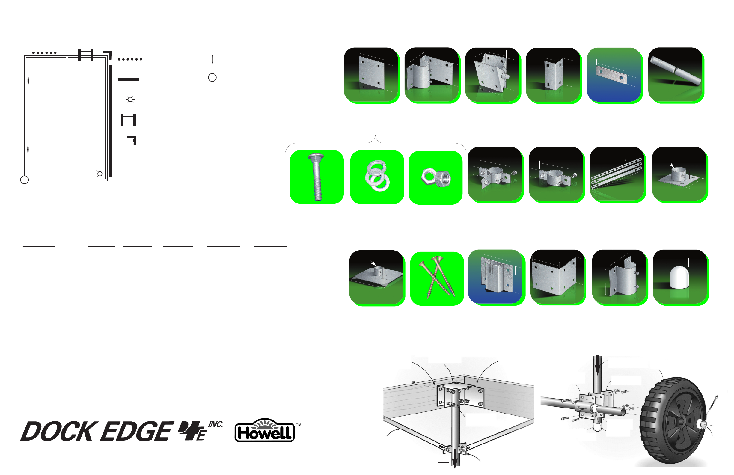
STATIONARY DOCK HARDWARE
®
HOW
HOW
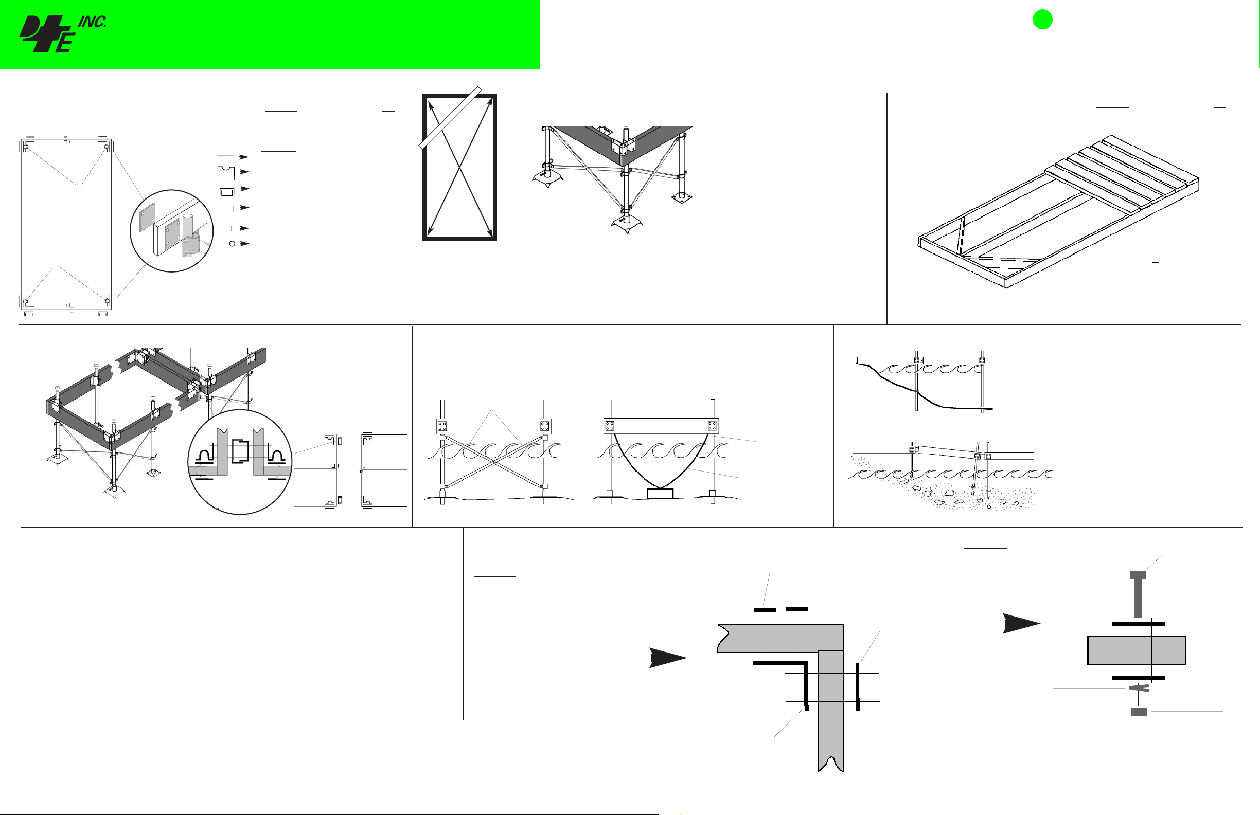
HOW TO BUILD A 4’ x 8’ Stationary Dock
Assemble main framework
1
Drill holes for 87-122-F
D
E
D
A
E
D
Connecting Dock Sections
H
G
B
I
H
F
H
D
C
H
E
D
J
I
A
Always use a backer plate
87-122-F on both sides of the
G
E
C
F
framework when attaching leg
pipe holders.
holders 86-101-F shown
TO GUIDE
TO GUIDE
LUMBER
Description QTY
A - Main dock frame 2” x 8” x 96” 2
B - Center truss: 2” x 8” x 92
C - End Cap: 2” x 8” x 69” 2
HARDWARE
D - Backer Plate 87-122-F 10
E - Corner Leg Holder 86-100-F 4
F - Hinge Connector* 86-103-F 2
G - Joist Corner 95-122-F 2
H - Washer Plate 99-006-F 4
I - Leg Pipe, 6’8” 93-168-F 4
Hardware Fastener Kit 85-150-F 5
* Required if af
Optional side leg
fixing dock sections or a ramp together.
When attaching dock sections, leg
braces should always be used on the
leading edge of each dock section for
stability.
Where dock sections are attached, the
outer backer plate 87-122-F used for
the corner leg holder may simply be
replaced by the hinge connector
86-103-F as shown.
3/4
”1
USE GREEN LABELLED OR GREEN DOT COMPONENTS
FOR STATIONARY DOCK CONSTRUCTION
Reinforcing the leg pipes and choosing a leg
2
Z
Squaring your Dock Structure
Check the squareness by measuring from corner to
corner of the frame in an “X” pattern as shown. The
measurement should be +/- 1/4” between each other. Lock
the framework into square by temporarily securing a piece
of lumber (Z) across one corner as shown above.
SSTTAATTIIOONNAARRYY DDOOCCKK
4
AANNCCHHOORRAAGGE
Leg Braces
pipe base for bottom conditions
M
O
M
Q
E
O
Description QTY
Note: Several options and combinations
vailable for stabilizing a stationary
a
N
O
M
O
M
Q
Description QTY
S - Chain Retainer 99-013-F 2
H - Washer Plate 99-006-F 4
Galvanized chain: 5/16” x approx 48’
Hardware Fastener Kit 85-150-F 1
Anchorage Min. 125lb ea. 2
N
P
dock structure
O - Leg Brace Set 89-101-F 6
M - Corner Leg Brace Holder 87-107-F 4
N - Side Leg Brace holder 93-105-F 4
Q - Bottom Pad 94-102-F 4
or
P - Base Plate 86-102-F 4
NOTE: consideration should be given to the
type of bottom the dock will be resting on.
Bottom Pads, 94-102-F are larger than the
Base Plate 86-102-F and therefore better for
soft or sandy bottoms where the dock structure
requires a more stable footing. Alternatively, if
necessary, the base plate may be fastened to a
concrete slab or footing if for additional
stability or in areas of strong currents or wave
action.
Assemble decking and connector
3
hinges. (hinges if attaching to
another dock structure or shore
ramp
GRADED SHORELINE INSTALLATION
Description QTY
- Decking: 2” x 6” x 72” 16
R - Decking Screws: #10 x 3” 96
Shown with optional corner braces added for
extra rigidity.
• Use hinge 86-103-F between dock
segments.
• Allow leg pipes to protrude below the bottom
pads by approximately 12” so they will
become embedded in the lake bed.
Adjust leg pipe holders on leg pipes to level
•
dock segments before tightening.
F
E
D
Backer Plates not
used with hinges
E
D
Tools Required for the average Dock Build
Drive leg pipes no less than 12” into lake bed,
24” if dock to be used for a boat mooring.
IMPORTANT TIPS
S
(excludes sizing/ cutting of structural wood members)
- Electric Drill
- 3/16” drill bit
- 3/8” drill bit or auger
- 3/8” drive Socket wrench set
- Wrench set
- #2 Robertson (square) bit drive for decking screws
- Pencil
- Measuring tape
- 2-1/2” hole saw (not required if mounting leg pipes on outer dock face)
Always use washer plates
(99-006-F), backer plate
(87-122-F) or mating hardware
components together.
Framework of the dock
structure should be
sandwiched between hardware
pieces at all joint locations as
shown. (sample only, other
configurations possible)
IMPORTANT: DockEdge+ Inc. assumes no responsibility or liability for the accuracy or representation of the graphic illustrations shown in this hardware guide. These graphic illustrations are not
intended to be architectural drawings, and are not to be substituted for engineered drawings. Each is intended as a guideline ONL
accurate in all uses and applications. Individual dock structures may vary by necessity, preference or design. It may be necessary to vary the amount of materials listed in this guide depending on dock size,
material usage, necessity and/ or the severity of the conditions to which the dock structure is subjected to. All graphic illustrations are based on the use of conventional framework of 2” x 6” lumber and decking
lumber. Freeboard may be adjusted by using 2”x8” or 2”x10” lumber. Substitutions in lumber and hardware placement may effect floatation.
Printed in Canada 020711
Y. DockEdge+ Inc. does not warrant the quantities and/ or bill of materials to be
Anchorage
to suit
S
Wood Frame
86-104-F
Inside Corner
Chain Retainer
Galvanized Chain
5/16” to 3/8”
99-006-F
Washer Plate
UNEVEN SHORELINE INSTALLATION
Always use a lock
washer with each
carriage bolt usage
to prevent bolts
87-122-F
Backer Plate
loosening over
time.
•
• Allow the dock segment with the highest
• Adjust leg pipe holders on leg pipes to
Lock Washer
Use hinge 86-103-F between dock
segments.
drop in elevation to act as a ramp to a
maximum of 15º angle.
sufficient contact with lake bed. Tighten leg
holders.
Carriage
Bolt
Wood Frame
Nut
DDoocckk AAcccceessssoorriiees
s
Spot Protection
Bumper Profile
Solar Lighting
Ladder
Corner Bumper
Cleats
Dock Bumper Wheels
AALLSSOOAAVVAAIIL
Mooring Whips
Life Ring Buoys
Portable Cleats
L
ABLE
Dock Hardware and Fasteners you will need (referenced by item letter)
/4
1
”
1/4
5
”
1/4
5
D
7-122-F
8
pipe from deforming wood causing
bolt loosening and dock shifting.
Backer Plate. Prevents
”
/4
1
5
”
E
6-100-F
8
Mounts on inside corner of framework.
8 pieces each included in Fastener Kit 85-150-F
7/8
5
Corner Leg Holder.
”
2
F
6-103-F
8
to join dock sections or a fixed ramp
to the dock at varying angles.
Includes hinge pin.
5”
1/2
”
5
onnector Hinge. Used
C
1/4
5
”
G
5-122-F
9
reinforce stringer joints.
1/2
”
2
1/4
5
Joist Corner. Used to
”
H
99-006-F Washer Plate.
1/4
5
”
1/2
”
1
I
93-168-F (6’ 8”)
Galvalume Leg Pipe.
J
Carriage Bolts
Hardware Requirements for other dock sizes
Quantity Required (4’ x 8’ or 8’ x 8’ sections)
Description Product # 4 x 8 Dock 8 x 8 Dock 4 x 16 Dock 8 x 16 Dock
Joist Corner 95-122-F 24 24 56 56
Washer Plate 99-006-F 4 4 4 4
Corner Leg Holder 86-100-F 4 4 8 8
Side Leg Holder (optional) 86-101-F 4 4 8 8
Corner Leg Brace Holder 87-107-F 4 4 8 8
Side Leg Brace Holder 93-105-F 4 4 8 8
Adjustable Leg Brace Set 89-101-F 6 6 12 12
Leg Pipe 6’8” 93-168-F 4 4 8 8
Bottom Pad 94-102-F 4 4 8 8
Base Plate 86-102-F May be used in combination with or in place of Bottom Pad 94-102-F
Pipe cap 91-111-F 4 4 8 8
Chain Retainer 99-013-F 2 (Use at outer most end of dock structure up to 16’ & every 16’ thereafter)
Backer Plate 87-122-F 8 8 16 16
Hardware Fastener Kit 85-150-F 5 6 10 12
Connector Hinge* 86-103-F 2 2 2 2
Corner Plate** 86-104-F 2 2 2 4
* Connector Hinges used for between-dock and shore-to-dock or ramp connections and not required for individual dock sections
** Corner plate hardware to be used at dock-to-shore connection of dock where leg support is not required
K
Lock Washers
1/4
2
”i.d.
/2
1
”
2
1/8
”
1
11”
Q
94-102-F Bottom Pad. Use for
soft bottom applications. Allows leg
pipe to extend through to lake bed for
lateral support. Pointed corners.
Attaching rolling wheels for dock insertion & removal
87-122-F
Backer Plate
1
1
L
Nuts
R
Deck Screws
86-104-F
Corner Plate
3/4
4
”
/4
1
”
1
M
87-107-F Corner Leg Brace
Holder. Use when attaching an
89-101-F Leg brace from corner to
side legs for stability.
6”
5
S
99-013-F Chain retainer. Mount on
outer dock face for easy access and
adjustment of anchorage.
87-122-F
Backer Plate
/4
3
4
1/4
1
”
N
93-105-F Leg Brace Holder. Use
with Leg Brace Set to connect leg
pipes for stability.
/8
7
5
”
/4
1
”
86-104-F Corner Plate. Used on
inside corners for increased strength
and where a leg pipe is not installed/
necessary.
86-101-F
Side Leg Holder
1”
”
25”
2
O
89-101-F Leg Brace Set. Extends
up to 72”. Use with Leg Brace
Holders to connect legs for stability.
Optional Hardware
/4
1
5
”
/4
1
”
5
7/8
5
”
86-101-F Side Leg Holder. Can
be mounted inside or outside of the
dock frame.
93-168-F
2
2
Galvalume Leg Pipe
86-101-F
Side Leg Holder
86-102-F Base Plate. Used as a
footing. May be bolted to a 2” x 6”
piece of lumber and joined to an
adjacent base plate for stability.
91-111-F Leg Cap. Use to cover
raw leg pipe edges. Gives dock the
finishing touch.
Dock Wheel
1/4
” i.d.
P
2”
2
/8
3
5
2
”
/4
1
”
/2
1
”
Cotter Pin
®
THE FINEST QUALITY DOCK HARDWARE AND MARINE ACCESSORIES www.dockedge.com
89-101-F
Leg Brace Set
93-168-F
Galvalume Leg Pipe
86-100-F
Corner Leg
Holder
87-107-F
Leg Brace Holder
91-111-F
Plastic Leg
Cap
87-122-F
Backer Plate
PVC Bushing
PVC Bushing
 Loading...