

Dock Edge Mooring Whip User Manual
Premium & Ultimate
&
Mooring Whip Installation
Instructions
IMPORTANT
CAUTION
I M P O R T A N TN O T E ST O ENSURE A SAFE, SECURE INSTALLATION & WARRANT Y O U R NEW M O O R I N GW H I P S
IMPORTANT: Ensure that you have purchased the appropriate
DockEdge Mooring Whip for your application.
ations are more critical factors than length in estimating your requirements.
3 YEAR Limited Warranty
against defects in materials and workmanship.
MOORING WHIP PRODUCT CHART
WHIP Model
#3200 8ft. (2.44m) Craft Up to 18 ft. (5.49m)
#3400 & 3450 12 ft. (3.66m)Craft Up to 23 ft. (7.01m)
#3600 & 3650 14 ft. (4.27m)Craft Up to 28 ft (8.53m)
#3800 & 3850 16 ft. (4.88m)Craft Up to 33 ft (10.06m)
WHIP Model
#3100 8ft. (2.44m) Craft Up to 18 ft. (5.49m)
#3120 12ft. (3.66m) Craft Up to 23 ft. (7.01m)
Warning: Failure to follow proper installa-
tion instructions voids warranty and may
lead to product failure and/ or property
damage.
Note: Some mooring areas may be too
rough for any type of tie-up system.
Weight and water level vari-
“A”
Premium & Ultimate
Up to 2,500 lb. (1133Kg) Capacity
Mooring Distance From Dock - Minimum 3 Ft. (0.91m)
Up to 5,000 lb. (2267Kg) Capacity
Mooring Distance From Dock - Minimum 4 Ft. (1.22m)
Up to 10,000 lb. (4535Kg) Capacity
Mooring Distance From Dock - Minimum 5 Ft. (1.52m)
Up to 20,000 lb. (9070Kg) Capacity
Mooring Distance From Dock - Minimum 5 - 6 Ft.
(1.52 - 1.83m)
Up to 2,000 lb. (907Kg) Capacity
Mooring Distance From Dock - Minimum 3 Ft. (0.91m)
Up to 4,000 lb. (1814Kg) Capacity
Mooring Distance From Dock - Minimum 4 Ft. (1.22m)
Premium & Ultimate Whips
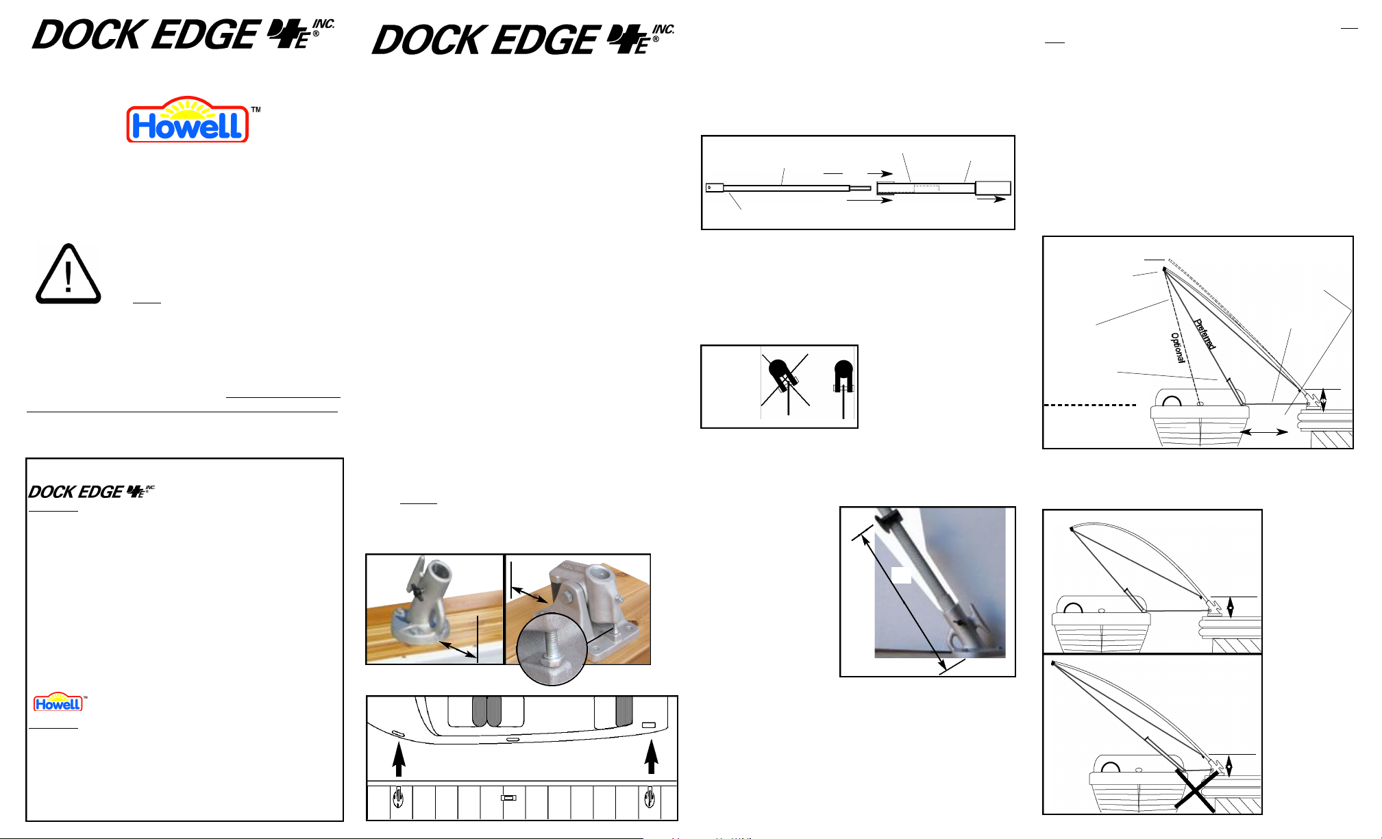
1- INSTALLING THE MOORING WHIP BA S E S
Mooring whips require a firm, secure footing for mounting.
- The recommended location for mooring whips is on the side of the
dock which is most protected from winds. This is preferrable to cause
the boat to stay clear of the dock rather than be forced towards it.
- Locate the cast aluminum bases 4-5” from the edge of the dock.
Fig. #1a & 1b
- Align the whip bases with their respective cleats on the bow and stern of
the boat making sure that the whips are perpendicular to the edge of the
dock. Fig. #1c
The general rule is that the span between the whips should be
approximately 2/3 of the boats’ overall length. Install additional
cleat(s) on the boat if necessary to retain the 2/3 rule. Space whip
bases accordingly for such an application.
ATTENTION: Fig. #1b also illustrates the location of a bolt at the
rear of the rocker base which is used to adjust the freeplay of a
completed whip assembly. This bolt should be adjusted only
enough to eliminate any freeplay between the rocker base arm and
the rubber bushing.
NOTE: In applications where side cleats are unavailable a center bow
or stern cleat of the boat may be used.
- Mark the location of the mounting holes for the bases and drill
through the plank with a 1/8” drill bit. Lag down the whip bases with
the lag bolts and washers supplied.
NOTE: Concrete docks will require lag bolts and masonry plug
inserts. Softwood docks such as cedar should have a 3/8” hole
through the dock at each mounting hole location of the
drilled
base and 3/8” bolts or “carriage” bolts and use washers, lockwashers and nuts or locking nuts in place of the 3/8” lag bolts sup plied with your mooring whip kit.
Fig. 1a
Fig. 1c
4 to 5”
4 to 5”
Align Bases with cleats to be used
Fig. 1b
FREEPLAY ADJUSTMENT
BOLT
2- WHIP ASSEMBLY (where applicable)
Models 3400, 3450, 3600, 3650, 3800 & 3850 are two part assemblies.
Carefully follow the instructions for 2-part assemblies. (See Fig. #2)
With a threading motion turn the top portion of the mooring whip into
the base section until it is fully seated. Approximately 18 inches of the
upper section should be retained inside the lower section of the whip
assembly.
Fig. 2
Upper Section
Whip Tip or roller
Reinforcement Collar
18in.
Insert into
Lower Section
Lower Section
Insert into
Mounting Base
3- WHIP MOUNTING & PREPARATION
- Feed the whip lines over the line rollers at the tips. Ensure whip tip
rollers are parallel to the dock surface. (Fig. #3)
- Insert the whip into the base, making sure the whip is fully seated in
the base and so that the whip line is hanging straight down. OR for
models incorporating a tip pulley, align the pulley so that it is
perpendicular to the dock surface. (Fig. #3)
Fig. 3
ROLLER
TIP
Once the tip has been aligned, tighten the thumb screw on the
whip base only enough to prevent the whip from lifting out of the
base. Overtightening may damage the fiberglass strand and
integrity of the whip.
Pole Cleat - Attach the
pole cleat no more than 14
inches from the whip base.
See Fig. #4.
The pole cleat can be used to
wrap the boats’ whip line
around for quick release and
ease of manouvering the
watercraft towards the dock
when required.
4-
INSTALLATION OF WHIP LINES
- Tie off the dock side end of each whip line to the pole or base cleat,
Fig. #4 making sure there is sufficient excess line at both ends to
allow for tie-up of the boat with the tensioner, and release of line
tension at the dock.
- To adjust for proper tension on the mooring whip lines slip the loops
from the lines through the bow and stern cleats of the boat.
Using the sliding tension adjuster, place enough tension on the line
to just pull the whip tip down.(See Fig. #5 & #6)
Whip tip & roller pin assembly
is ready for use. Optional
wheel (not included with
Howell models) may be
installed at the users discretion.
Fig. 4
Cleat not
included with
14”
Howell Whips
CAUTION: When adjusting whip and/ or spring line tensions Do
Not over-torque the whip. Pull each whip tip down in inches, as
the whip is in total length, ie. 8ft. - 8 inches, 12 ft. - 12 inches, 14
ft. - 14 inches, 16 ft. - 16 inches.
CAUTION: For installation of mooring whips on stationary docks in
locations where water levels fluctuate more than 2 ft., mooring whips
without a rocker base MUSTbe adjusted periodically to compensate for
these variations. Failure to make adjustments to spring and whip line
tension in such conditions may result in damage to the whips and void
the manufacturers warranty, see Fig. #5 thru #9. Adjustments are seldom necessary on floating docks, as the dock and boat will rise and fall
accordingly. Alternatively, Mooring whips with a rocker base (models
3450, 3650 & 3850) may be installed for such applications. The rocker
base should adequately adjust for tidal variations that could exceed the
abilities of whips with a rigid non-pivoting base.
Fig. 5
Under Load
Whip Line
Bow & Stern
(Keep as vertical as possible)
Tensioner
Optional Bow Cleat
Usage if Bow or Stern Cleats
Unavailable (See 6A)
CORRECT INSTALLATION
At Rest
See Product Chart “A” regarding this dimension.
Bow Line
See “A”
14 in.
INCORRECT INSTALLATIONS
Fig. 6a
Fig. 6b
Under no circ u m s t a n c e s
should any
mooring whip
be installed
with an excess
of tension as
14 in.
shown in thesed i a g r a m s .
Doing so will
affect the mooring whips ability
to protect your
water craft and
will void the
m a n u f a c t u r e r s
warranty.
14 in.
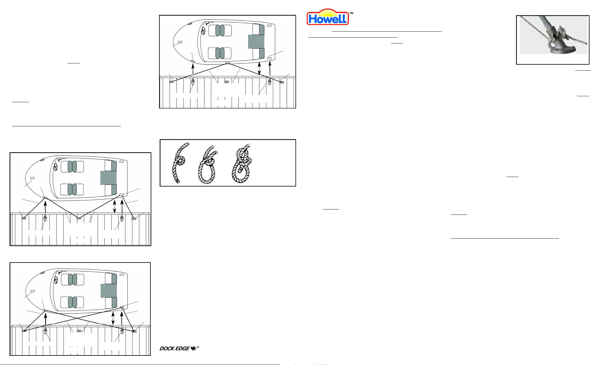
5 - INSTALLATION OF SPRING LINES
- Refer to the Figures 5 through 9 for proper configuration and spring
line attachment.
- Spring lines should be attached to the built-in cleat of solid mooring
whip bases and bow and stern lines should be attached to the
integral eyelet of each whip base. Pivoting/ rocker base whip bases must
use separate dock cleats as shown in Fig. #7, 8 & 9.
IMPORTANT: Spring lines
MUST always be used. Tension must be
equal on all lines. Install additional cleat(s) on the boat if necessary to
retain the 2/3 rule Discussed in Section 1 “Installing The Mooring Whip
Bases”.
The boat should lie the distance specified in product chart “A” for your
whips.
DO NOT attempt to retain the “Distance from Dock” dimension
shown in chart “A” if using oversized whips. Larger whips are
intended for larger watercraft with a wider beam and therefore able
to retain the recommended “Distance from Dock” dimension.
Distance from dock should never be less than 3-4ft.
“M” Method - Whips & Whip Lines Not Shown
Fig. 7
Optional
Bow Cleat
Bow Line
Optional Bow Line
Dock Cleat
Side Cleat
Cast Aluminum Base
Spring Lines (2)
MUSTBE USED
AT EACH DOCKING
DOCK
See “A”
Mounting Lags &
Washers, each base
Stern Cleat
Stern Line
Optional Stern
Line Dock Cleat
“X” Method - Whips & Whip Lines Not Shown
Fig. 8
Optional
Bow Cleat
Optional Bow Line
Dock Cleat
Bow Line
Side Cleat
Cast Aluminum Base
Spring Lines (2)
MUSTBE USED
AT EACH DOCKING
DOCK
See “A”
Mounting Lags &
Washers, each base
Stern Cleat
Stern Line
Optional Stern
Line Dock Cleat
“V” Method - Whips & Whip Lines Not Shown
Fig. 9
Optional
Bow Cleat
Optional Bow
Line Dock Cleat
Side Cleat
Cast Aluminum Base
Spring Lines (2)
MUSTBE USED
AT EACH DOCKING
DOCK
See “A”
Mounting Lags &
Washers, each base
- Loops in the ends of the bow, stern and spring lines can be made
using a “bowline knot” as shown in Fig. #10.
- Once the bow, stern and spring lines have been made to the correct
length they should be left on the dock for easy tie-up upon return.
Fig. 10
Bowline Knot
1- Form a loop
2- Pass the rope’s free
end through the loop.
3- Loop the end
around the main
1 2 3
rope and back
through the first loop
a g a i n .
IMPORTANT: When spring lines have been cut to length, seal the cut
ends of the lines with a flame (lighter, match or small torch) to prevent
fraying.
WINTER STORAGE:
For winter storage remove the whips from the
aluminum bases only. Leave the aluminum bases mounted to the dock.
Two(2) piece whip assemblies can be separated into the upper and
lower halves for more compact storage. It is recommended that whips
be stored in a location that remains above freezing such as a basement
or heated garage.
Your Premium 0r Ultimate Whip kit includes
the following parts and materials:
2- Whip poles 2- Whip lines 2- Aluminum bases
- Lag bolts (for base) (AR) Spring line - Washers (for base)
2- Locking screws (for base) 1- Instruction sheet
2- Cleat Ass’y (2Pc) 2- Line Tensioners 2- Screws & Nuts
1- Optional whip tip pulley (for cleat ass’y)
For answers to your questions or to enquire about other Dock Edge+ p r o d u c t s call, write or
fax us at:
®
35 Armthorpe Road, Brampton, Ontario, Canada, L6T5M4
Phone:(800)-295-3625 www.dockedge.com
Stern Cleat
Optional Stern
Line Dock Cleat
Mooring Whip Installation
CAUTION: Installation of mooring whips on stationary docks
where water levels fluctuate more than 2 ft.:
Mooring whips with a fixed angle base
cally to compensate for these variations. Failure to make adjustments to
spring and whip line tension in such conditions may result in damage to
the whips and void the manufacturers warranty, see Fig. #5 thru 9.
Adjustments are seldom necessary on floating docks, as the dock and
boat will rise and fall together accordingly.
1- INSTALLING THE MOORING WHIP BA S E S
Mooring whips require a firm, secure footing for mounting.
- The recommended location for mooring whips is on the side of the dock
which is most protected from winds. This is preferrable to cause the
boat to stay clear of the dock rather than be forced towards it.
- Locate the aluminum bases 4-5” from the edge of the dock. Fig. # 1a
- Align the whip bases with their respective cleats on the bow and stern of
the boat making sure that the whips are perpendicular to the edge of the
dock. Fig. #1c
The general rule is that the span between the whips should be
approximately 2/3 of the boats’ overall length. Install additional
cleat(s) on the boat if necessary to retain the 2/3 rule. Space whip
bases accordingly for such an application.
NOTE: In applications where side cleats are unavailable a center
bow or stern cleat of the boat may be used.
- Mark the location of the mounting holes for the bases and drill
through the plank with a 1/8” drill bit. Lag down the whip bases
with the lag bolts and washers supplied.
NOTE: Concrete docks will require lag bolts and masonry plug
inserts. Softwood docks such as cedar should have a 3/8” hole
through the dock at each mounting hole location of the
drilled
base and 3/8” bolts or “carriage” bolts and use washers, lockwashers and nuts or locking nuts in place of the 3/8” lag bolts
supplied with your mooring whip kit.
2- WHIP ASSEMBLY (where applicable)
Carefully follow the instructions for 2-part assemblies. (See Fig. #2)
With a threading motion turn the top portion of the mooring whip into
the base section until it is fully seated. Supplied epoxy is for use with
Howell 3120 Whips.
3- WHIP MOUNTING & PREPARATION
- Feed the whip lines through the whip line roller pins at the tips.
- Insert the whip into the base, making sure the whip is fully seated in
the base and so that the whip line is hanging straight down. Ensure
roller pins are parallel to the dock surface. See .(Fig. #3)
Once the tip has been aligned, tighten the thumb screw on the
whip base only enough to prevent the whip from lifting out of the
base. Overtightening may damage the fiberglass strand and
integrity of the whip.
4- INSTALLATION OF WHIP LINES
- Tie off the dock side end of each whip line to the pole or base cleat,
making sure there is sufficient excess line at both ends to allow for
tie-up of the boat with the tensioner, and release of line tension at
the dock.
M U S T be adjusted periodi-
4- INSTALLATION OF WHIP LINES CONT’D
- To adjust for proper tension on
the mooring whip lines slip the
loops from the lines through the
bow and stern cleats of the
boat. Using the sliding tension
adjuster, place enough tension
on the line to just pull the whip
tip down.(See Fig. #5 & #6)
CAUTION: When adjusting whip and/ or spring line tensions
Sample Base Cleat Tie-Off
Do Not
over-torque the whip. Pull each whip tip down in inches, as the whip
is in total length, ie. 8ft. - 8 inches, 12 ft. - 12 inches.
CAUTION: For installation of mooring whips on stationary docks in locations where water levels fluctuate more than 2 ft., fixed base whips
MUST
be adjusted periodically to compensate for these variations. Failure to
make adjustments to spring and whip line tension in such conditions may
result in damage to the whips and void the manufacturers warranty, see
Fig. #5 thru #9.
5 - INSTALLATION OF SPRING LINES
- Refer to the illustrations below for proper configuration and spring line
attachment.
- Spring lines should be attached to the built-in cleat of solid mooring
whip bases and bow and stern lines should be attached to the integral
eyelet of each whip base. Pivoting/ rocker base whip bases must use
separate dock cleats as shown in Fig. #7, 8 & 9.
IMPORTANT: Spring lines
MUST always be used. Tension must be
equal on all lines. Install additional cleat(s) on the boat if necessary to
retain the 2/3 rule Discussed in the Section “Installing Your Mooring Whip
Bases”.
The boat should lie the distance specified in product chart “A” (top of
page 1) from and parallel to the dock.
DO NOT attempt to retain the “Distance from Dock” dimension
shown in chart “A” (page 1) if using oversized whips. Larger whips
are intended for larger watercraft with a wider beam and therefore
able to retain the recommended “Distance from Dock” dimension.
Distance from dock should never be less than 3-4ft.
- Loops in the ends of the bow, stern and spring lines can be made
using a “bowline knot” as shown in Fig. #10.
- Once the bow, stern and spring lines have been made to the correct
length they should be left on the dock for easy tie-up upon return.
IMPORTANT: When spring lines have been cut to length, seal the cut
ends of the lines with a flame (lighter, match or small torch) to prevent
fraying.
WINTER STORAGE: For winter storage remove the whips from the aluminum bases only. Leave the aluminum bases mounted to the dock. It
is recommended that whips be stored in a location that remains above
freezing such as a basement or heated garage.
Your kit includes the following parts and materials:
2- Whip poles 2- Whip lines (tensioners attached)
6- Lag bolts (for bases) (AR) Spring line 6- Washers (for bases)
2- Locking screws (for bases) 1- Instruction sheet
2- Line Tensioners (see whip lines) 2- Aluminum bases
1- Epoxy (2-part) for use on Howell model 3120 Whips
 Loading...