

FLOATING DOCK HARDWARE
®
HOW
HOW
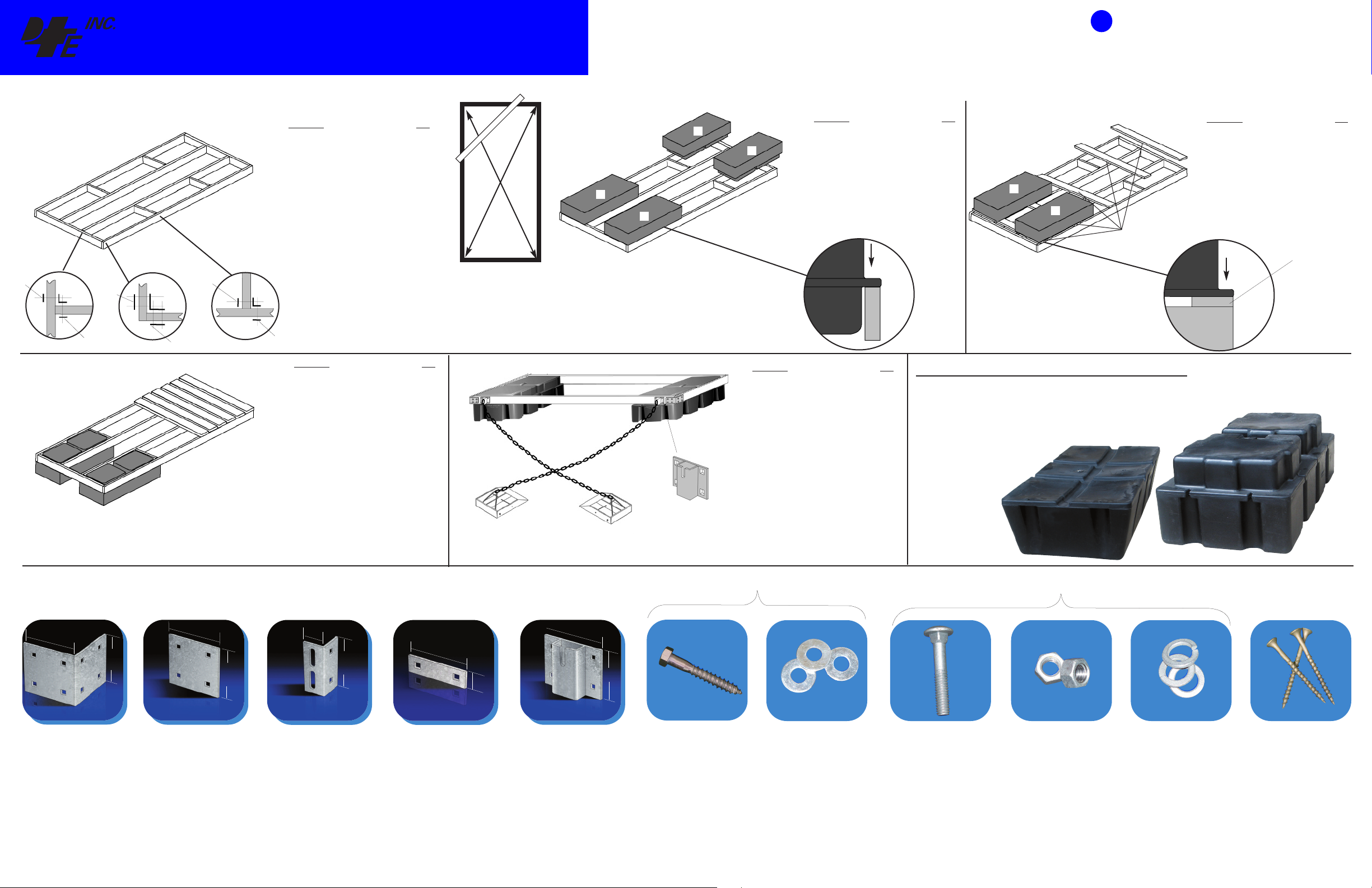
HOW TO BUILD A 6’ x 12’ Floating Dock
TO GUIDE
TO GUIDE
USE BLUE LABELLED OR BLUE DOT COMPONENTS
FOR FLOATING DOCK CONSTRUCTION
Washer
Plate
Assemble main framework
1
Drill holes for 93-122-F
G
F
D
F
C
D
F
F
oist
J
orner
C
Assemble decking and connector hinges.
3
(hinges if attaching to another dock
structure or shore footing)
Washer
Plate
Backer
Plate
F
F
G
A
B
B
G
H
D
G
C
G
A
F
D
F
Description QTY
- Main dock frame: 2” x 8” x 144” 2
A
B - Center truss: 2” x 8” x 140
- End Cap: 2” x 8” x 69” 2
C
D - Inside Corner: 92-104-F 4
F - Backer Plate 93-122-F 8
G - Joist Corner 99-002-F 2
H - Washer Plate 99-006-F 4
E - Carriage Bolt: 1/2” x 2
V - Lock Washers 1/2” 40
T - Nuts 1/2” 40
Note: items E, V & T are all included in packages of 8 in
Hardware Fastening Kit
85-100-F
3/4
”1
1/2
”40
Z
Assemble center joists to
2
fit recessed flanges of
99-246-F floats
J
J
J
J
Description QTY
Note: floats may be secured to framework &
tringers
s
J - Floats: 99-246-F 4
loat Fastener Kit 85-125-F 3
F
For flush mount floats such as the Howell™ 400,
99-242-F, refer to Step 2a.
ay floats into position on the dock framework
L
and mark each mounting hole location. Drill
3/16” pilot holes at each location to be used.
2a
Assemble optional rails
for flush mount floats
if desired
J
J
M
M
M
N
M
M
Description QTY
for FLUSH MOUNT Dock FLOATS (optional)
using Howell™ 400 float 99-242-F
J - 400 Float 99-242-F 5
M -Optional float rails: 2” x 6” x 72” 7
N - Screws: #10 x 3” 80
Float Fastener Kit 85-125-F 4
Lay floats into position on the mounting rails
and mark each mounting hole location. Drill
3/16” pilot holes at each location to be used.
Mounting
Rail
Howell 550™ 99-246-F
Inside
Corner
Backer
Plate
Washer
Plate
Squaring your Dock Structure
Joist
Corner
Washer
Plate
Description QTY
O
O -Decking: 2” x 6” x 72” 26
L - Screws: #10 x 3” 156
Lay the dock frame upside down on a flat surface in order to easily install floats. Check the
squareness by measuring from corner to corner of the frame in an “X” pattern as shown.
The measurement should be +/- 1/4” between each other
.
Lock the framework into square by temporarily securing a piece of lumber (Z) accross
one corner as shown below.
FFLLOOAATTIINNGG DDOOCCKK AANNCCHHOORRAAGGE
4
P
99-013-F
Chain
Retainer
OAT
FL
Description QTY
E
P Chain Retainer 99-013-F 2
F - Washer Plate 99-006-F 4
Galvanized chain: 5/16” x approx 48’
E - Hardware Fastener Kit 85-100-F 1
Q Anchorage Min. 125lb ea. 2
Joist or
main
frame
FLOTATION CAPACITY FORMULAE, REQUIRED # OF FLOATS
(Square Footage of Dock x 25* )/ Flotation Capacity per float = # of Floats required
Sample: (100ft2 x 25)/ 400 = 6.25 or 6 x Model 400 floats
* based on an average required floatation of 25 lb. / sq. ft. of
dock surface area.
FLOAT
Joist or
main
frame
NOTE: Decking lumber is milled to have one “cap” or “crown”
surface which will allow water to flow away from the deck surface.
When mounting the deck boards to the dock frame it is recom
mended to fasten the decking “cap”/ “crown” up.
-
Dock Hardware and Fasteners you will need (referenced by item letter)
7/8
5
”
1/4
5
”
D
92-104-F Inside Corner. For lighter
duty applications where an outside
corner is not necessary.
1/4
”
5
1/4
5
”
F
93-122-F Backer Plate. Used to
sandwich wood framing when
another piece of hardware isn’t used.
prevents bolt loosening and
pull-through.
G
99-002-F Joist Corner. Use to
mount stringers with 99-006-F washer
plates. Also use as a backer plate to
prevent cleats from pulling out.
1/2
”
2
1/4
5
1/4
5
”
”
1/2
1
H
99-006-F Washer Plate.
Q
Anchorage
to suit
Q
8 pieces each included in Fastener Kit 85-125-F
6”
1/4
5
. Holds
”
L
Lag Bolts
”
P
99-013-F Chain Retainer
chain up to 1/2” to secure the dock in
position.
IMPORTANT: DockEdge+ Inc. assumes no responsibility or liability for the accuracy or representation of the graphic illustrations shown in this hardware guide. These graphic illustrations are not
intended to be architectural drawings, and are not to be substituted for engineered drawings. Each is intended as a guideline ONLY. DockEdge+ Inc. does not warrant the quantities and/ or bill of materials to be
accurate in all uses and applications. Individual dock structures may vary by necessity, preference or design. It may be necessary to vary the amount of materials listed in this guide depending on dock size,
material usage, necessity and/ or the severity of the conditions to which the dock structure is subjected to. All graphic illustrations are based on the use of conventional framework of 2” x 6” lumber and decking
lumber. Freeboard may be adjusted by using 2”x8” or 2”x10” lumber. Substitutions in lumber and hardware placement may effect floatation.
Printed in Canada 020711
P
Howell 400™
99-242-F
8 pieces each included in Fastener Kit 85-100-F
S
Flat Washers
E
Carriage Bolts
T
Nuts
V
Lock Washers
N
Deck Screws
Tools Required for the average Dock Build
(excludes sizing/ cutting of structural wood members)
- Electric Drill
- 1/2” drill bit or auger
- 3/8” Socket wrench
- 9/16” socket
- 9/16” wrench
- #2 Robertson (square) bit drive for decking screws
- Pencil
- 3/16” drill bit
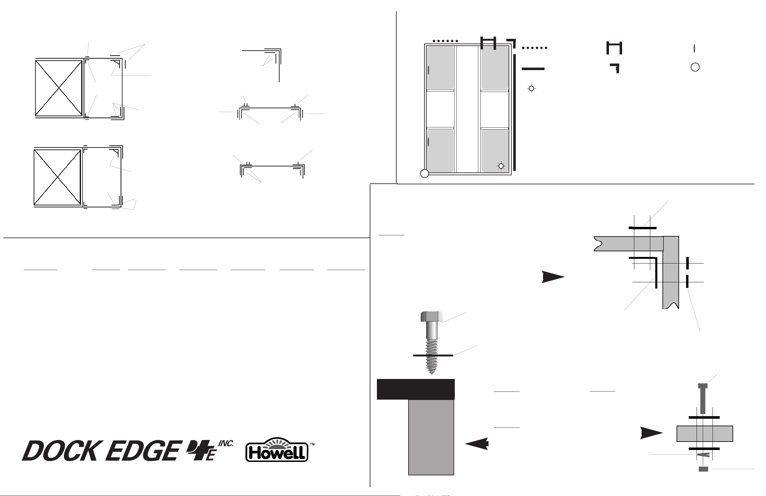
Optional Floating Dock Hardware and Connector Hinge Placement
99-006-F
Washer Plate
93-122-F
acker Plate
B
DDoocckk AAcccceessssoorriiees
s
Spot Protection
Ladder
C
leats
93-122-F
Backer Plate
2-116-F
9
Howell™
Float
Howell™
loat
F
99-002-F
Joist Corner
92-104-F
Inside
Corner
Inside Anchor Corner
93-122-F
Backer Plate
16-F
92-1
Anchor Corner
Inside
93-122-F
Backer Plate
93-122-F
Backer Plate
99-010-F
Female
Corner Hinge
99-011-F
Female T
Connector
92-104-F
Inside Corner
93-122-F
Backer Plate
99-012-F
Male T
Connector
93-122-F
Backer Plate
99-009-F
Male Corner
Hinge
Hardware Requirements for other dock sizes
Quantity Required
Description Product # 10 x 10 Dock 12 x 12 Dock 6 x 20 Dock 8 x 20 Dock 10 x 20 Dock
Joist Corner 99-002-F 24 24 56 56 82
Inside Corner 92-104-F 4 4 2 4 4
Washer Plate 99-006-F 16 16 24 24 32
Chain Retainer 99-013-F 2 2
Backer Plate 93-122-F 8 8 8 6 6
Howell 550 Float* 99-246-F 4 6 6 8 10
Howell 400 Float (alternate) 99-242-F 6 8 8 10 12
Hardware Fastener Kit 85-100-F 15 15 17 21 28
(8 pack Carriage Bolts, Lock Washers & Nuts)
Float Fastener Kit 85-125-F 4 6 6 8 9
(8 pack Lag Bolts & Flat Washers)
Male Corner Hinge 99-009-F 1 or 2
Female Corner Hinge 99-010-F 1 or 2
Connector Pin 96-111-F 2 2 2
Male T Connector 99-012-F 1 or 2 1 or 2
Female T Connector 99-011-F 1 or 2 1 or 2
®
Bumper Profile
olar Lighting
S
IMPORTANT TIPS
Always use washer plates (99-006-F), backer plate
(93-122-F) or mating hardware components together.
Farmework of the dock structure should
be sandwiched between hardware pieces at all joint
locations as shown.
(sample only, other configurations possible)
Lag Bolt
Flat Washer
Float Mounting
Dock Frame
Always drill pilot
holes for lag bolt
installation.
Always use a large
flat washer at each
lag bolt installation
as shown
Corner Bumper
AALLSSOOAAVVAAIIL
ooring Whips
M
Life Ring Buoys
Portable Cleats
Wood Frame
92-104-F
Inside Corner
Always use a lock
washer with each
carriage bolt usage
to prevent bolts
loosening over
time.
Lock Washer
L
BLE
A
Backer Plate
Dock Bumper Wheels
93-122-F
99-006-F
Washer Plate
Carriage
Bolt
Wood Frame
THE FINEST QUALITY DOCK HARDWARE AND MARINE ACCESSORIES www.dockedge.com
Nut
 Loading...