

®
MODULAR
DOCK 2
GO
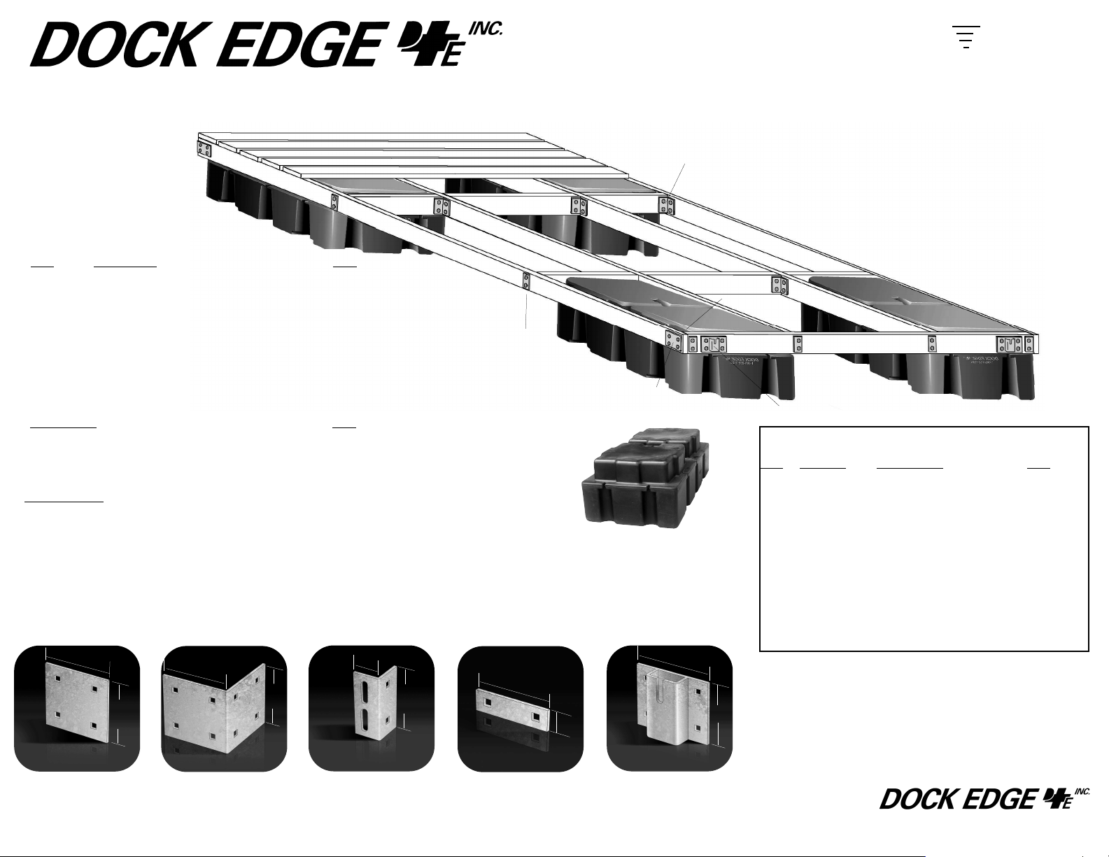
6’ x 12’ Floating, Main Dock Construction Guide and Bill Of Materials
LUMBER REQUIRED
REF
Description QTY
a 2” x 6” x 12’ Outside Stringers 2
b 2” x 6” x 69” Ends Stringers 2
c 2” x 6” x 141” Short Cross Stringers 2
d 2” x 6” x 21” Inside Blocker 4
e 2” x 6” x 24” Inside Blocker 2
f 2” x 6” x 6’ Deck Boards 24
ADDITIONAL HARDWARE REQUIRED
Description
QTY
1/2” x 2 1/2” Carriage Bolts and nuts & lock washers 92 each
3/8” x 2” Lag Bolts & Washers 40 ea.
Chain (zinc coated) length to suit anchorage method and depth
ANCHORAGE: DockEdge+ recommends that the dock be anchored
to shore. The furthest extension of the dock should be anchored to
appropriate dock anchors at the end of the dock using chain of
sufficient size and the chain retainers 99-013-F in this dock kit.
NOTE: If attaching modular sections, anchorage should be
maintained at the outer-most end of the dock assembly and
additional placement of anchorage at each modular attachment
point.
1/4
5
”
1/4
5
”
A
93-122-F Backer Plate. Used to
sandwich wood framing when another piece of hardware isn’t used.
Prevents bolt loosening and pullthrough.
7/8
5
”
1/4
5
”
B
92-104-F Inside Corner. For lighter
duty applications where an outside
corner is not necessary.
C
99-002-F Joist Corner. Use to
mount stringers with 99-006-F
washer plates. Also use as a
backer plate to prevent cleats from
pulling out.
d
C
c
b
a
a
c
c
b
B
D
c
b
A
E
FLOATATION REQUIRED
Note: The Howell 550 has
recessed flange areas.
HOWELL™ 550
550lb. / 250 Kg Capacity
QTY: 4
1/2
2
”
1/4
5
1/4
5
”
D
99-006-F W
”
asher Plate.
1/2
”
1
E
99-013-F Chain Retainer. Holds
chain up to 1/2” to secure the dock
in position.
6”
1/4
5
DOCK HARDWARE INCLUDED
Part# Description QTY
REF
A 93-122-F Backer Plate 6
B 92-104-F Inside Corner 4
C 99-002-F Joist Corner 16
D 99-006-F Washer Plate 28
E 99-013-F Anchor Chain Retainer 2
Additional Hardware required for modular attachment to an
additional DOCK-2Go Section Part# 85-205-F
99-011-F Female “T” Connector 2
99-012-F Male “T” Connector 2
96-111-F Connector Pin 2
93-122-F Backer Plate 4
IMPORTANT: DockEdge+ Inc. assumes no responsibility or liability for the accuracy or representation of the graphic illustrations shown in this hardware guide. These graphic illustrations
are not intended to be architectural drawings, and are not to be substituted for engineered drawings. Each is intended as a guideline ONLY. DockEdge+ Inc. does not warrant the quantities
and/ or bill of materials to be accurate in all uses and applications. Individual dock structures
”
may vary by necessity
rials listed in this guide depending on dock size, material usage, necessity and/ or the severity
of the conditions to which the dock structure is subjected to.
All graphic illustrations are based on the use of conventional framework of 2” x 6” lumber and
decking lumber. Freeboard may be adjusted by using 2”x8” or 2”x10” lumber. Substitutions in
lumber and hardware placement may effect floatation.
, preference or design. It may be necessary to vary the amount of mate
35 Armthorpe Rd., Brampton, ON, Canada, L6T 5M4
800-295-3625 www.dockedge.com
-
®
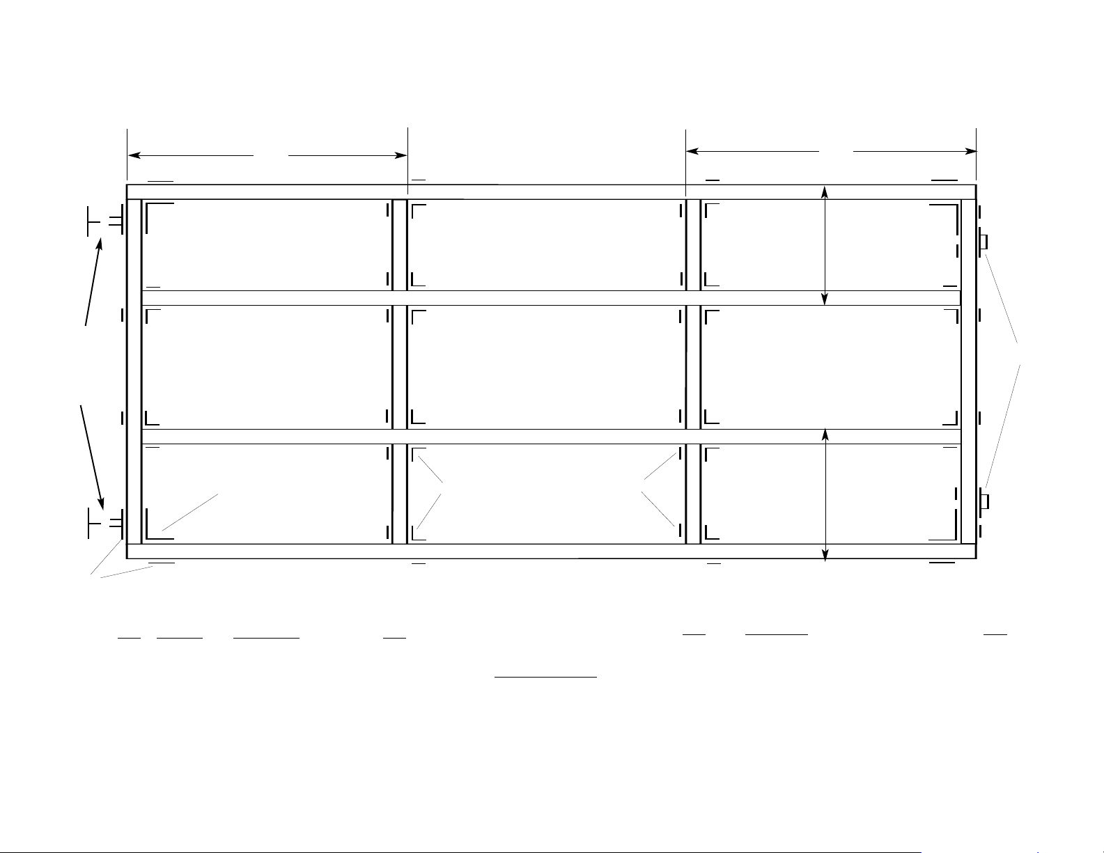
Typical Joint Configuration
Optional placement
of connectors for
modular assembly
(replaces backer
plates in these positions
48”
a
a
d
d
c
c
b
b
B
e
e
c
c
d
d
C
a
a
D
d
d
e
e
d
d
48”
24”
24”
b
b
E
A
DOCK HARDWARE INCLUDED
REF Part# Description QTY
A 93-122-F Backer Plate 6
B 92-104-F Inside Corner 4
C 99-002-F Joist Corner 16
D 99-006-F Washer Plate 28
E 99-013-F
Additional Hardware required for modular attachment
to an additional DOCK-2Go Section
99-011-F Female “T” Connector 2
99-012-F
1-F
1
96-1
93-122-F Backer Plate 4
Anchor Chain Retainer
Male “T” Connector 2
Connector Pin
2
2
}
Part# 85-205-F
OOLS REQUIRED
T
Hammer
Drill
5/8” Drill Bit
Socket and wrench Set
LUMBER REQUIRED
REF Description QTY
a 2” x 6” x 12’ Outside Stringers 2
b 2” x 6” x 69” Ends Stringers 2
c 2” x 6” x 141” Short Cross Stringers
d 2” x 6” x 21” Inside Blocker
e 2” x 6” x 24” Inside Blocker 2
f 2” x 6” x 6’
Deck Boards
2
4
24
 Loading...