

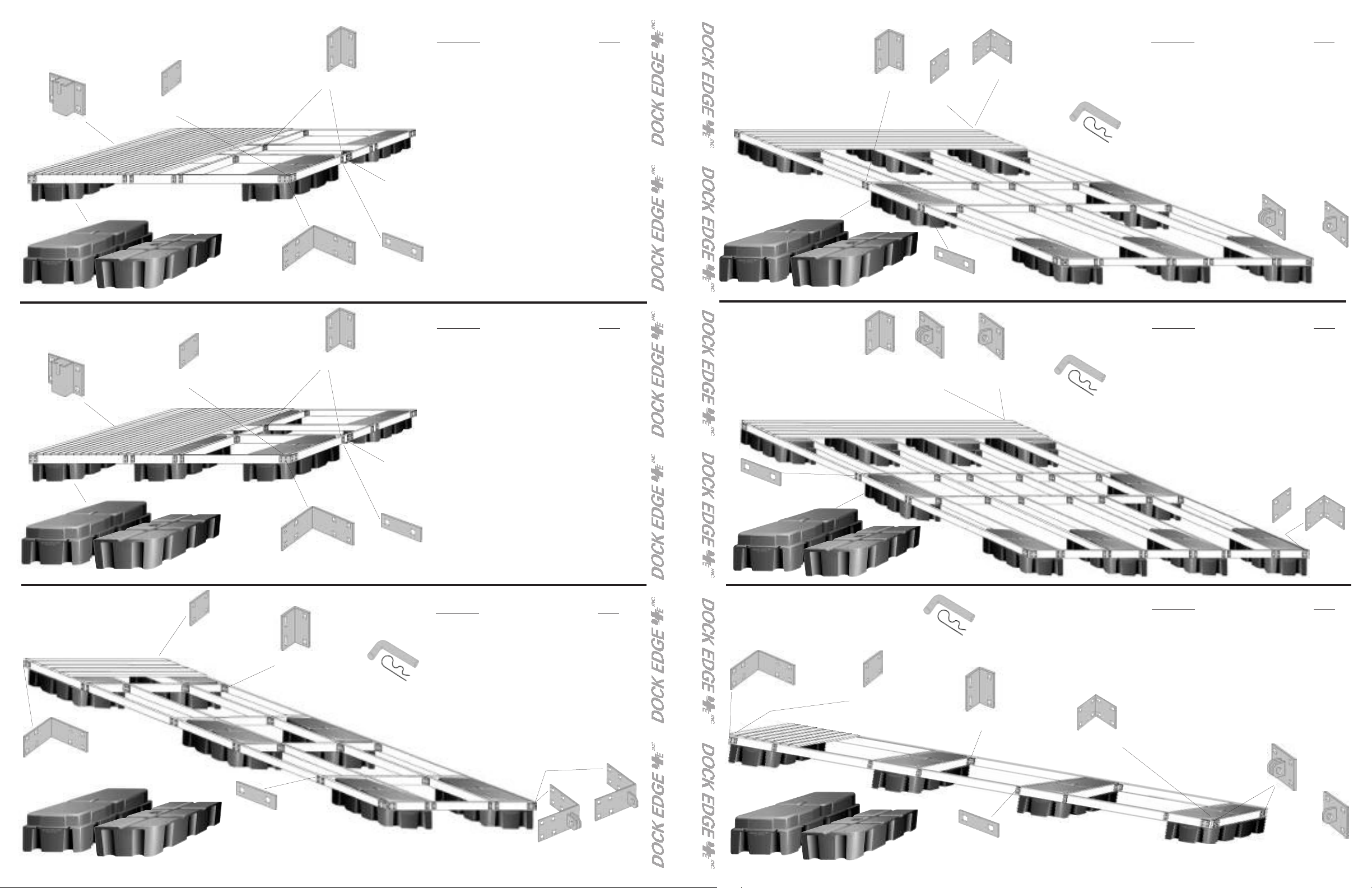
10 x 10
SWIM FLOAT
99-013-F
Chain
Retainer
Howell 550™
Howell 400™
12 x 12
SWIM FLOAT
99-013-F
Chain
Retainer
93-122-F
Backer Plate
93-122-F
Backer Plate
oist Corner
J
99-004-F
Outside
Corner
99-002-F
Joist Corner
99-002-F
99-013-F
Chain
Retainer
99-006-F
Washer Plate
99-013-F
Chain
Retainer
DOCK HARDWARE REQUIRED
Description QTY
99-004-F Outside Corner 4
99-002-F Joist Corner 24
99-006-F Washer Plate 16
99-013-F Chain Retainer 2
93-122-F Backer Plate 8
99-246-F Howell 550 Float 4
99-242-F Howell 400 Float 6
1/2” x 2 1/2” Carriage Bolts and nuts 116 each
3/8” x 2” Lag Bolts 32
Note: The Howell 550 has a recessed flange whereas the
Howell 400 has traditional top flange mount.
See rear cover for sample optional hardware placement for
corners and hinges and formulae for the recommended
number of floats to use for your dock project as well as an
IMPOR
OR
TANT note from DockEdge+.
DOCK HARDWARE REQUIRED
Description QTY
99-004-F Outside Corner 4
99-002-F Joist Corner 24
99-006-F Washer Plate 16
99-013-F Chain Retainer 2
93-122-F Backer Plate 8
99-246-F Howell 550 Float 6
99-242-F Howell 400 Float 8
1/2” x 2 1/2” Carriage Bolts and nuts 116 each
3/8” x 2” Lag Bolts 48
Note: The Howell 550 has a recessed flange whereas the
Howell 400 has traditional top flange mount.
See rear cover for sample optional hardware placement for
corners and hinges and formulae for the recommended
number of floats to use for your dock project as well as an
IMPORTANT note from DockEdge+.
OR
8 x 20
MAIN DOCK
99-002-F
Joist Corner
Howell 550™
Howell 400™
10 x 20
MAIN DOCK
99-002-F
oist Corner
J
See rear cover for sample optional hardware
placement for corners and hinges and formulae
for the recommended number of floats to use
for your dock project as well as an IMPORTANT note from DockEdge+
99-006-F
Washer Plate
3-122-F
9
Backer Plate
99-006-F
Washer Plate
99-011-F
Female T
onnector
C
92-104-F
Inside Corner
+
+
99-012-F
Male T
Connector
See rear cover for sample
optional hardware placement for
corners and hinges and formulae
for the recommended number of
floats to use for your dock project as well as an IMPORTANT
note from DockEdge+
96-111-F
Connector Pin
96-111-F
Connector
Pin
DOCK HARDWARE REQUIRED
Description QTY
99-012-F Male T Connector 1 or 2
99-011-F Female T Connector 1 or 2
96-111-F Connector Pin 2
92-104-F Inside Corner 4
93-122-F Backer Plate 6
99-002-F Joist Corner 56
99-006-F Washer Plate 24
99-246-F Howell 550 Float 8
99-242-F Howell 400 Float 10
1/2” x 2-1/2”” Carriage Bolts and nuts 168 each
3/8” x 2” Lag Bolts & Washers 60 each
Note: The Howell 550 has a recessed flange whereas the
Howell 400 has traditional top flange mount.
OR
1-F
99-01
Female T
Connector
+
+
99-012-F
Male T
Connector
DOCK HARDWARE REQUIRED
Description QTY
99-012-F Male T Connector 1 or 2
99-011-F Female T Connector 1 or 2
11-F Connector Pin 2
96-1
99-002-F Joist Corner 82
9-006-F Washer Plate 32
9
93-122-F Backer Plate 6
92-104-F Inside Corner 4
99-246-F Howell 550 Float 10
99-242-F Howell 400 Float 12
1/2” x 2-1/2” Carriage Bolts and nuts 224 each
3/8” x 2” Lag Bolts & Washers 72 each
Note: The Howell 550 has a recessed flange whereas the
Howell 400 has traditional top flange mount.
OR
93-122-F
Backer Plate
Howell 550™
Howell 400™
6 x 20
MAIN DOCK
99-004-F
Outside Corner
Howell 550™
Howell 400™
93-122-F
Backer Plate
99-004-F
Outside
Corner
99-006-F
asher Plate
W
DOCK HARDWARE REQUIRED
Description QTY
99-009-F Male Corner Hinge 1 or 2
99-010-F Female Corner Hinge 1 or 2
96-111-F Connector Pin 2
99-004-F Outside Corner 2
99-002-F
Joist Corner
96-111-F
Connector
Pin
99-006-F
Washer Plate
See rear cover for sample optional hardware placement for corners and hinges
and formulae for the recommended number of floats to use for your dock project
as well as an IMPORTANT note from DockEdge+.
93-122-F
99-002-F Joist Corner 56
99-006-F Washer Plate 24
99-246-F Howell 550 Float 6
99-242-F Howell 400 Float 8
1/2” x 2 1/2” Carriage Bolts and nuts 136 each
3/8” x 2” Lag Bolts & Washers 48 ea.
Note: The Howell 550 has a recessed flange whereas the
Howell 400 has traditional top flange mount.
Backer Plate
OR
99-010-F
Female Corner
Hinge
8
99-009-F
Male Corner
Hinge
Howell 550™
4 x 20
FINGER DOCK
99-004-F
Outside Corner
Howell 550™
93-122-F
Backer Plate
Howell 400™
Howell 400™
96-111-F
Connector
Pin
Washer Plate
99-002-F
Joist Corner
99-006-F
DOCK HARDWARE REQUIRED
Description QTY
99-011-F Female T Connector 1 or 2
99-012-F Male T Connector 1 or 2
96-111-F Connector Pin 2
99-002-F Joist Corner 12
99-006-F
92-104-F Inside Corner 2
99-004-F Outside Corner 2
93-122-F Backer Plate 6
99-246-F Howell 550 Float 4
99-242-F Howell 400 Float 6
1/2” x 2-1/2” Carriage Bolts and nuts 80 each
92-104-F
Inside Corner
See rear cover for sample optional hardware placement for corners and
hinges and formulae for the recommended number of floats to use for
your dock project as well as an IMPOR
3/8” x 2”
Note: The Howell 550 has a
recessed flange whereas the
Howell 400 has traditional top
flange mount.
TANT note from DockEdge+.
Washer Plate 24
OR
Lag Bolts & Washers 36 each
99-011-F
Female T
Connector
92-104-F
Inside Corner
+
+
99-012-F
Male T
Connector
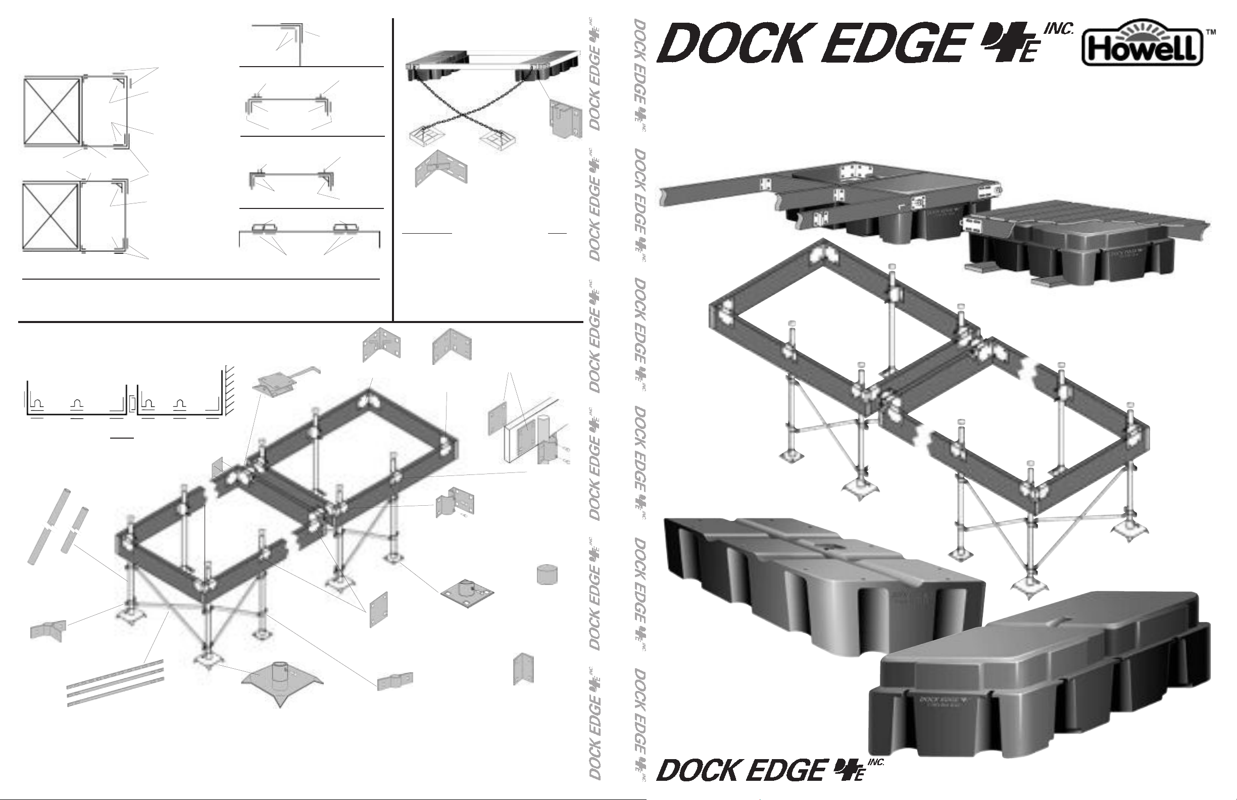
FLOATING DOCK HARDWARE
PLACEMENT for CORNERS &
HINGES
99-242-F
Howell 400™
Float
99-006-F
Washer Plate
99-242-F
Howell 400™
loat
F
99-002-F
Joist Corner
92-104-F
Inside
Corner
93-122-F
Backer Plate
99-001-F
HD Anchor Chain Corner
Backer Plate
Outside Corner
HD Anchor Chain Corner
Backer Plate
OR
92-116
Inside Anchor Corner
93-122-F
99-004-F
99-001-F
3-122-F
9
93-122-F
Backer Plate
99-011-F
emale T
F
Connector
92-104-F
Inside Corner
Backer Plate
99-010-F
orner Hinge
C
93-122-F
Backer Plate
HD Connector Hinge
93-122-F
Female
91-112-F
93-122-F
Backer Plate
99-004-F
Outside Corner
99-012-F
Male T
Connector
99-009-F
Male Corner
Hinge
99-001-F
HD Anchor
Chain Corner
FLOTATION CAPACITY FORMULAE, REQUIRED # OF FLOATS
Howell 550™: (Square Footage of Dock x 25 )/ 550= # of Floats
Howell 400™: (Square Footage of Dock x 25 )/ 400= # of Floats
Formulae based on average use of residential dock at 25lb/ ft.
2
FLOATING DOCK
ANCHORAGE
99-013-F
Chain
91-120-F
Dock Anchor
99-001-F
HD Anchor
Chain Corner (see placement guide)
Retainer
DOCK HARDWARE REQUIRED
Description QTY
99-013-F Chain Retainer 2
93-122-F
99-001-F HD Anchor Chain Corner 2
99-004-F Outside Corner 2
3/8” x 2-1/2” Carriage Bolts and nuts 16 each
1/2” x 2 1/2” Carriage Bolts and nuts 16 each
3/8” chain QTY to suit application
91-120-F Dock Anchor 2
Backer Plate 4
OR
OR
®
THE FINEST QUALITY DOCK HARDWARE AND MARINE ACCESSORIES
FLOATING AND STATIONARY DOCK
HARDWARE GUIDE
STATIONARY DOCK HARDWARE
Hardware Placement Guide
Correct Usage of Hardware with Backer Plates
Connector Hinge
(see placement guide)
87-122-F Backer Plate MUST be used On Opposite
Side Of All Fittings as shown in the Hardware
placement Guide above.
93-168-F &
93-110-F
Galvalume
Leg Pipe
87-107-F
Corner Leg
Brace Holder
86-103-F
91-116-F
Tie Down
Anchor
Corner
87-122-F
Backer Plate
(see placement guide)
86-104-F
Corner Plate
(see placement guide)
86-100-F
Corner Leg Holder
(see placement guide)
86-102-F
Base Plate
Proper hardware placement for 86-101 & 86-100
leg holders.
backer plates 87-122 as
shown.
Always use
86-101-F
Side Leg Holder
(see placement guide)
The Side Leg Holder
86-101-F may be
mounted inside the
dock framing or outside for convenient
adjustment if needed.
91-111-F
Plastic Leg Cap
Howell 400™
89-101-F
Adjustable Leg Brace Set
Max extension of 72”
94-102-F
Bottom Pad, 12”
93-105-F
Leg Brace Holder
95-122-F
Joist Corner Bracket
IMPORTANT: DockEdge+ Inc. assumes no responsibility or liability for the accuracy or representation of the graphic illustrations shown in this hardware guide. These graphic
illustrations are not intended to be architectural drawings, and are not to be substituted for engineered drawings. Each is intended as a guideline ONL
quantities and/ or bill of materials to be accurate in all uses and applications. Individual dock structures may vary by necessity, preference or design. It may be necessary to vary the amount
of materials listed in this guide depending on dock size, material usage, necessity and/ or the severity of the conditions to which the dock structure is subjected to.
All graphic illustrations are based on the use of conventional framework of 2” x 6” lumber and decking lumber. Freeboard may be adjusted by using 2”x8” or 2”x10” lumber. Substitutions in
lumber and hardware placement may effect floatation.
Y. DockEdge+ Inc. does not warrant the
Howell 550™
®
www
.dockedge.com
 Loading...