


AMIGO
AMIGO
Emergency Telephone
(EN 81-28 compliant)
DMG SpA
Via Quarto Negroni, 10
00040 CECCHINA (ROMA) • ITALIA
Tel. +39 06930251 • Fax +39 0693025240
info@dmg.it • www.dmg.it
AMIGO
- ETS8128CM
- ETS8128MR + ETS8128CS
Installation manual
Vers. 1.2 - English
NOTE:
Leave this document close to the emergency
telephone after installation
93010044_E_amigo_060324-0_EN.cdr
AMIGO
Emergency telephone
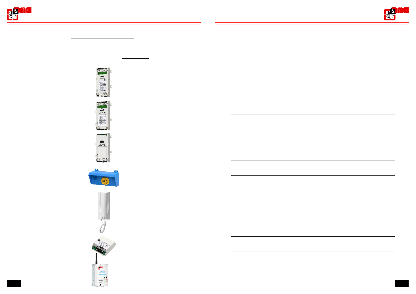
SYSTEM COMPONENTS
AMIGO
Emergency telephone
Code
ETS8128CM
ETS8128MR
ETS8128CS
ETS8128SL
Description
NOTES:
Car master device
Machine room device
Lift car slave device
Top/bottom of car slave device
CITCOC
ETS8128CH
ETSGSM
2312
Phone receiver
Feeder / battery charger
(optional)
GSM Module
AMIGO
Emergency telephone
AMIGO
Emergency telephone
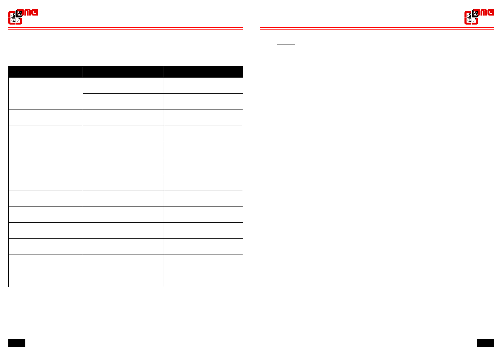
4. Troubleshooting
PROBLEM POSSIBLE CAUSE SOLUTION
Impossible to hear the operator voice
from the interphone (CITCOC)
CAUSA
Wrong connections Check connections
Volume is set at minimum Use the trimmer on ETS8128MR
device to raise the volume
INDEX
Product description
1. page 4
Technical features
1.1 ...............................................
Main functions
1.2 ..................................................
Available s page 4
1 . 3 ................................................
Basic alarm cycle setting for calls towards standard phone numbers
1.4
(Without DTMFcommunication protocol) . . . . . . . . . . . . . . . . . . . . . . . . . . . . . . page 5
Alarm cycle description for
1.5
(Without DTMFcommunication protocol) page 6
Basic alarm cycle setting for calls towards service center . . . . . . . . . . . . . . . . . page 7
1.6
1.7 calls towards service center . . . . . . . . . . . . . . . . . . page 8
Alarm cycle description for
1.8 External calls...................................................page 9
1.9 Operation with GSM network.......................................page 9
ignals
calls towards standard phone numbers
..............................
page 4
page 4
2. Installation guide page 10
"SINGLE DEVICE" configuration
2.1 ....................................
"3-DEVICE" configuration (EN 81-28 norm)
2 . 2 ............................
"4-DEVICE" configuration (EN 81-28 norm)
2.3 ............................
Installation instructions page 12
2.4 ............................................
2.5 Basic connections ...............................................page 13
2.6 Advanced connections (EN 81-28 norm) . . . . . . . . . . . . . . . . . . . . . . . . . . . . . . page 15
3. Programming
Function keys
3.1 ...................................................
Navigation page 16
3.2 .....................................................
3.3 Menu map .....................................................
3.4 Stand by.......................................................
Numbers from 1 to 6 page 18
3.5 .............................................
Service call number page 19
3 . 6 ..............................................
Number of attempts page 20
3.7 ..............................................
3.8 Incoming calls ..................................................
Dialing options page 22
3.9 ..................................................
Conversation time page 23
3 . 1 0 ...............................................
Voice messages
3.11 .................................................page 24
Site identification
3.12 ................................................page 26
Type of communication protocol
3.13 ....................................page 27
3.14 Call delay......................................................page 28
page 10
page 10
page 11
page 16
page 16
page 17
page 18
page 21
Troubleshooting
4.
page 30
30 3

AMIGO AMIGO
Emergency telephone
Product description
1. -
AMIGO is a programmable phone dialler for lifts complying with EN 81-28 norm requirements.
It is available in the following versions:
ar Master device (code ETS8128CM) - s 2.1 and 2.2
• C ee §
Machine room Master device (code ETS8128MR + ETS8128CS) - s 2.3
• ee §
Technical features
1.1 -
Power supply: 12Vdc
• +/- 15%
Absorption in stand-by:
• 38mA +/- 15%
Absorption during the call cycle: 150mA
•
ptional: Feeder/battery charger (code ETS8128CH)
•O
• Dimensions : 90x150x20 mm Weight : 160 gr.
Main functions
1.2 -
• Store capacity up to 6
phone number dedicated to service calls
•1
• Recordable
Possibility of storing two customized messages associated to "Low battery charge" and
•
"Regular operation" inputs
Programmation unit with LCD screen and keyboard (16 keys)
•
ialler status visible on LCD display
•D
• Two-way communication
“Low battery charge” outbound call
•
• Management of i
Manual dialing feature to check phone line availability
•
• Inter
• Local or remote alarm reset management
• Alarm filters management in case of working system or open doors with cage at floor
• Local or remote management of “wait for call status”
"Site identification” message
phone system between lift car and machine room (only with "Machine room" version)
phone numbers for emergency calls
time programmable by the user
ncoming system check calls
Emergency telephone
1.3 - Available s
• "Alarm sent" - "Alarm registered" signal management
ignals
4
29
AMIGO
Emergency telephone
AMIGO
Emergency telephone
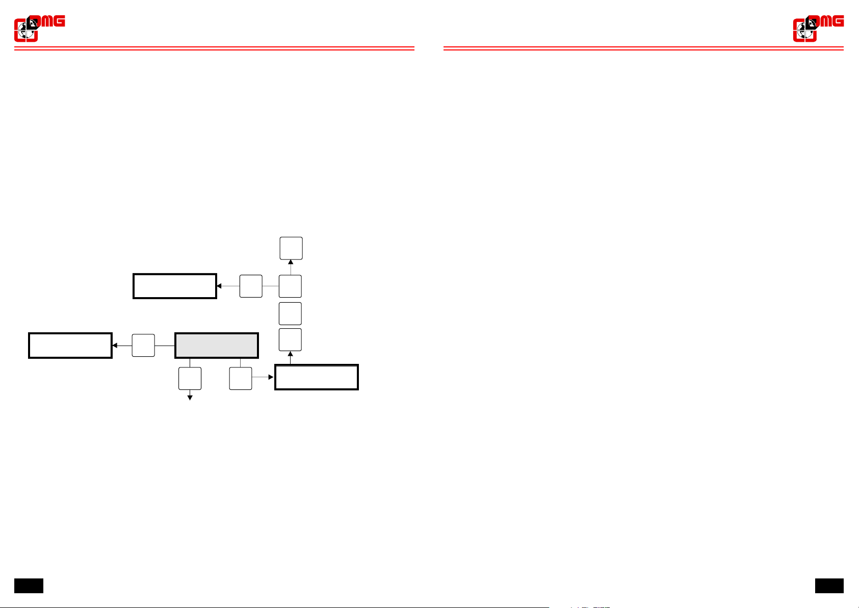
3.14 - Call delay
When set on “No delay”, the autodialler starts the alarm cycle immediately upon activation of the
alarm pushbutton positioned on one of the alarm devices.
When set on “5 sec delay”, the autodialler starts the alarm cycle only after 5 seconds of continuous
activation of the alarm pushbutton positioned on one of the alarm devices (to avoid accidental calls).
To set “Call delay”, press WRITE to access programming mode, then press “1” to set “5 sec delay”
or “0” to set “No delay”. Press OK to store the setting (If OK is not pressed within 30 seconds, the
setting is cancelled and the system goes back to Stand by).
NEXT
1st number
Stand by
Stand by
DMG
Amigo XX vX.X
DMG
Amigo XX vX.X
ESC
Call delay
NEXT WRITE
ESC
To store
OK
No delay
0
5 sec delay
1
Call delay
(5 sec delay/no delay)
1.4 - Basic alarm cycle setting for calls towards standard phone numbers
(Without DTMFcommunication protocol)
1) Enter in programming mode (see § 3.4)
2) Record the phone numbers to be called in case of emergency (see § 3.5)
3) Record the “Service Call” phone number where LOW BATTERY CHARGE and REGULAR
OPERATION service calls must be forwarded (see § 3.6)
4) Select the desired number of alarm cycles (see § 3.7)
5) Select the type of “Incoming calls” (see § 3.8)
6) Select tones or pulses mode (see § 3.8)
7) Select conversation time (see § 3.10)
8) Make sure that the message forward option is enabled (see § 3.11)
9) Record the SITE IDENTIFICATION message (see § 3.11)
10) Record the REGULAR OPERATION message (see § 3.11)
11) If the installation is provided with optional battery charger ETS8128CH (see § 2.6.2) record the
LOW BATTERY CHARGE message (see § 3.11)
12) Make sure that the “No protocol” option is enabled (see § 3.13)
13) Select the type of “Call delay” (see § 3.14)
Notes:
- If you do not want to enable the SITE IDENTIFICATION message, deselect the message
forward option (see § 3.11) and disregard § 8-9
- The first phone number must be always recorded, otherwise the alarm cycle will not be triggered
1st number
If no key is entered within 30 seconds, the autodialler will automatically get back to stand-by.
28
5
 Loading...