How it Works
Log In / Sign Up
Buy Points
How it Works
FAQ
Contact Us
Questions and Suggestions
Users
D Link
Loading...
W
Wir DIR-615-K2
Wireless & Ethernet Products
WL-211F
WL2600APA1
3
WL3140APA1
2
WL3150A1
WL3230APA1
WL3600APA1
WL3610APA1
3
WL6600APA1
2
WL6610APA1
WL6610APB1
2
WL6610APEB1
WL6620APSA1
WL6700APA1
WL7620APA1
WL8610APA1
WL8620APA1
WL8620APEA1
2
WL8710APA1
WLG122C1
WLG510C1
WLG630E1
WLG820B1
WM110A1
WM110B1
WM112A1
WM152A2
WM152A3
WM1561
WM156A2
WM156A3
WM156A5
WM156A6
WM156A7
WM157B1
WM158B1
WM158D1
WM221B1
2
WM311A1
WM800AA1
WM800BA1
WMP-A12
WNA-1330
2
WNA-2330
2
WP902A1
WR113A1
3
WR116A1
2
WR116A2
WR117A1
WR118A1
WR330A1
WR510A1
WR512A1
WR530A1
WR710A1
WR710B1
WR712C1
WR730A1
WR730B1
WR755A1
2
WR810A1
WR830A1
WR920VA1
WR920VA1-1
2
WR922C2
WR922C3
2
WR925A2
2
WR930A1
2
WR953B1
2
WR961C1
3
WUA-1340
3
WUA1340A1
WUA-2340
4
WUA2340A1
X
XNW224A1
Z
z anteną zewnętrzną (DWP-812KT)
Loading...
Loading...
Nothing found
WR118A1
Users Manual
97 pgs
2.25 Mb
0
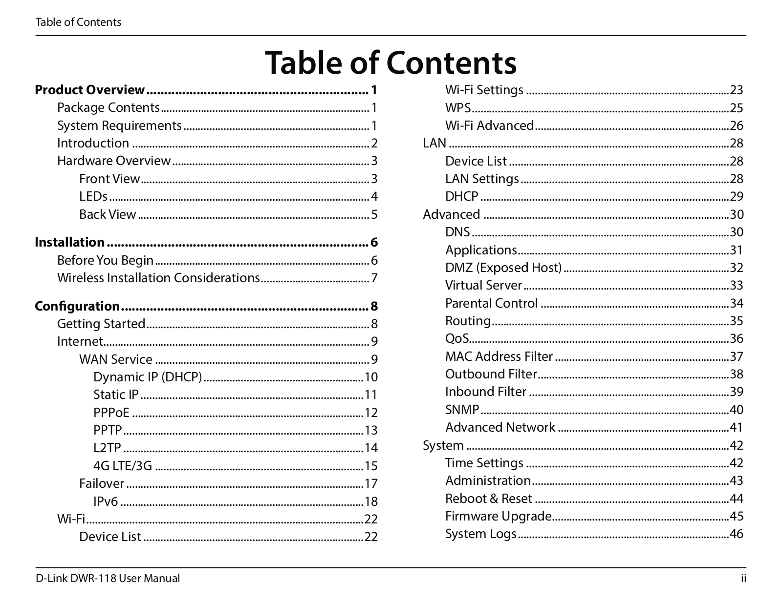
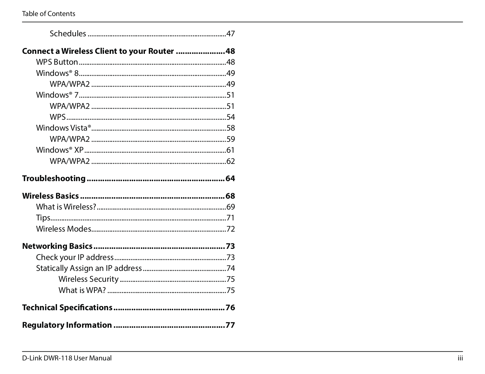
Table of contents
Loading...
D Link WR118A1 Users Manual
...
D Link Users Manual
Download
Specifications and Main Features
Frequently Asked Questions
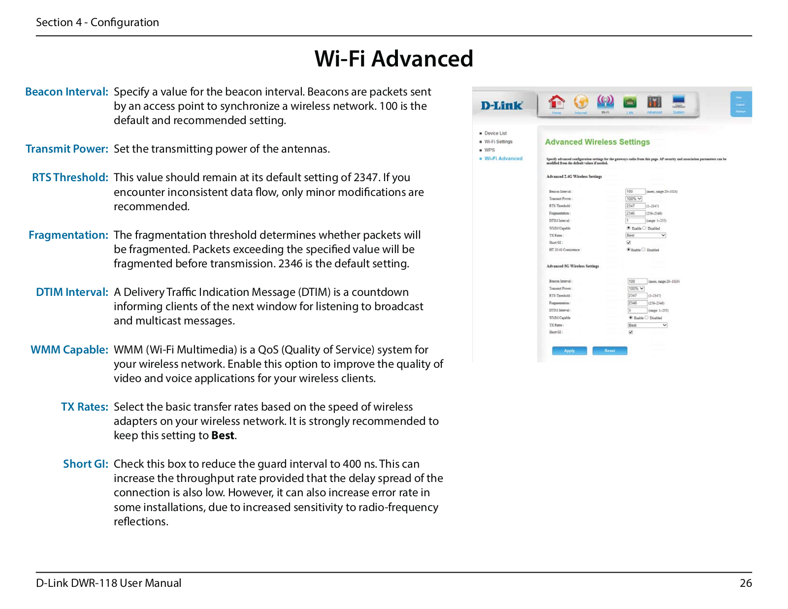
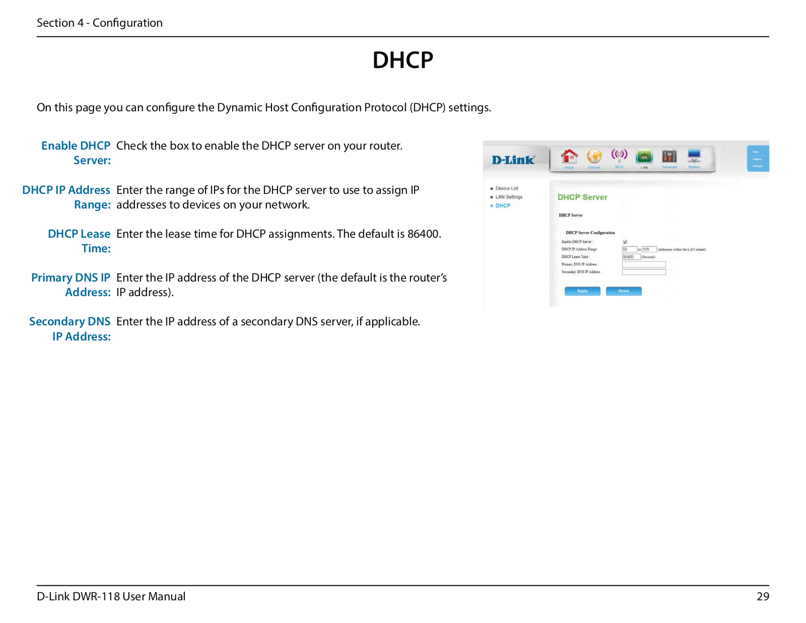
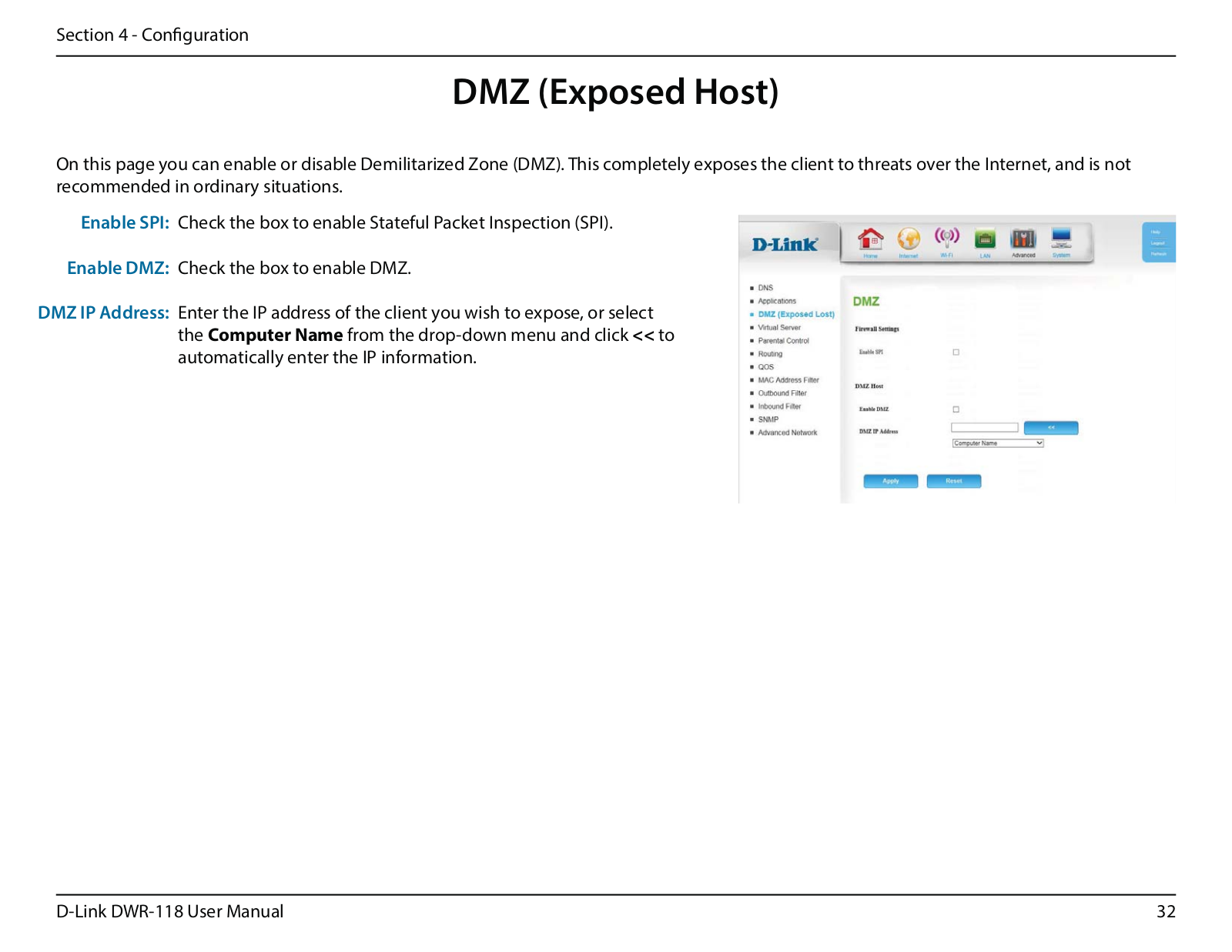
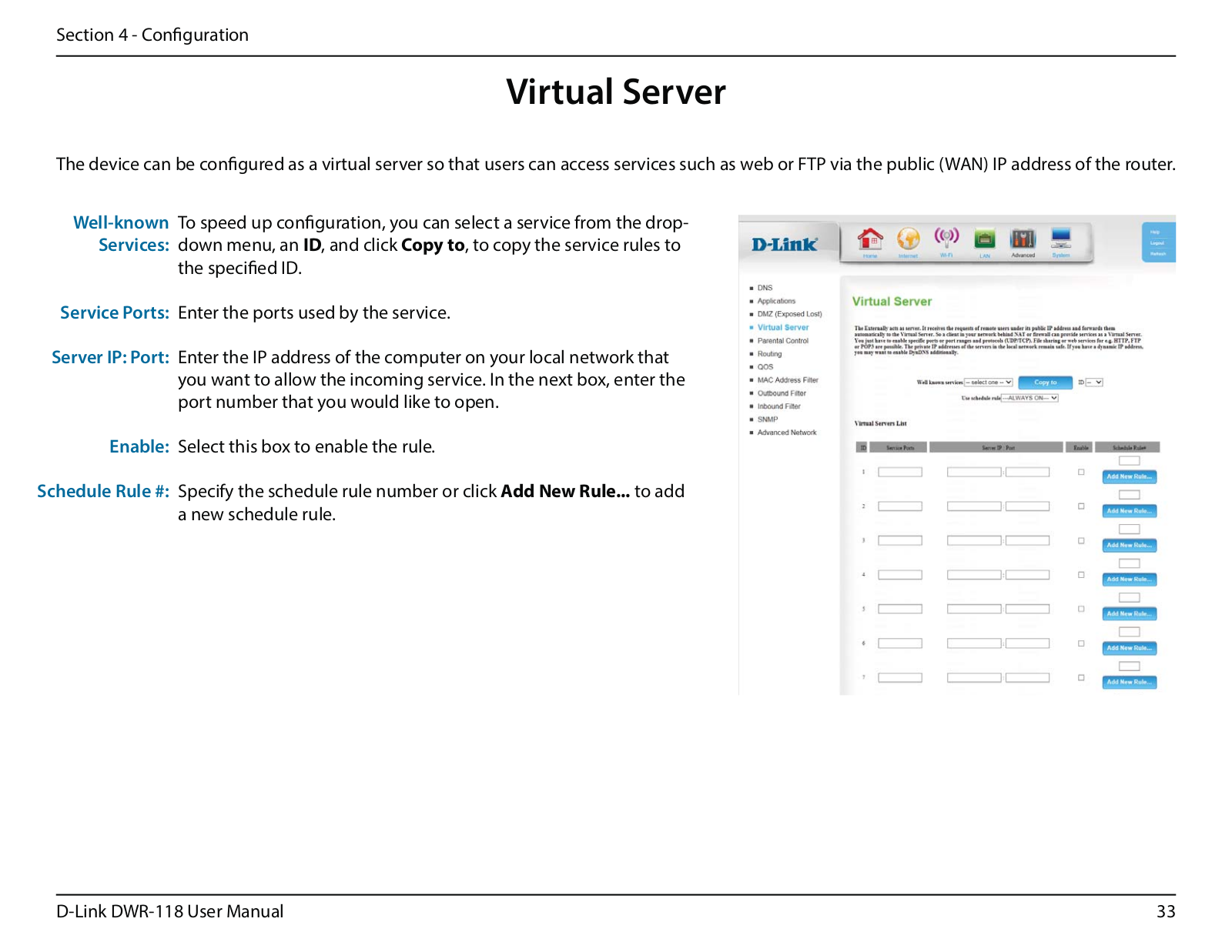
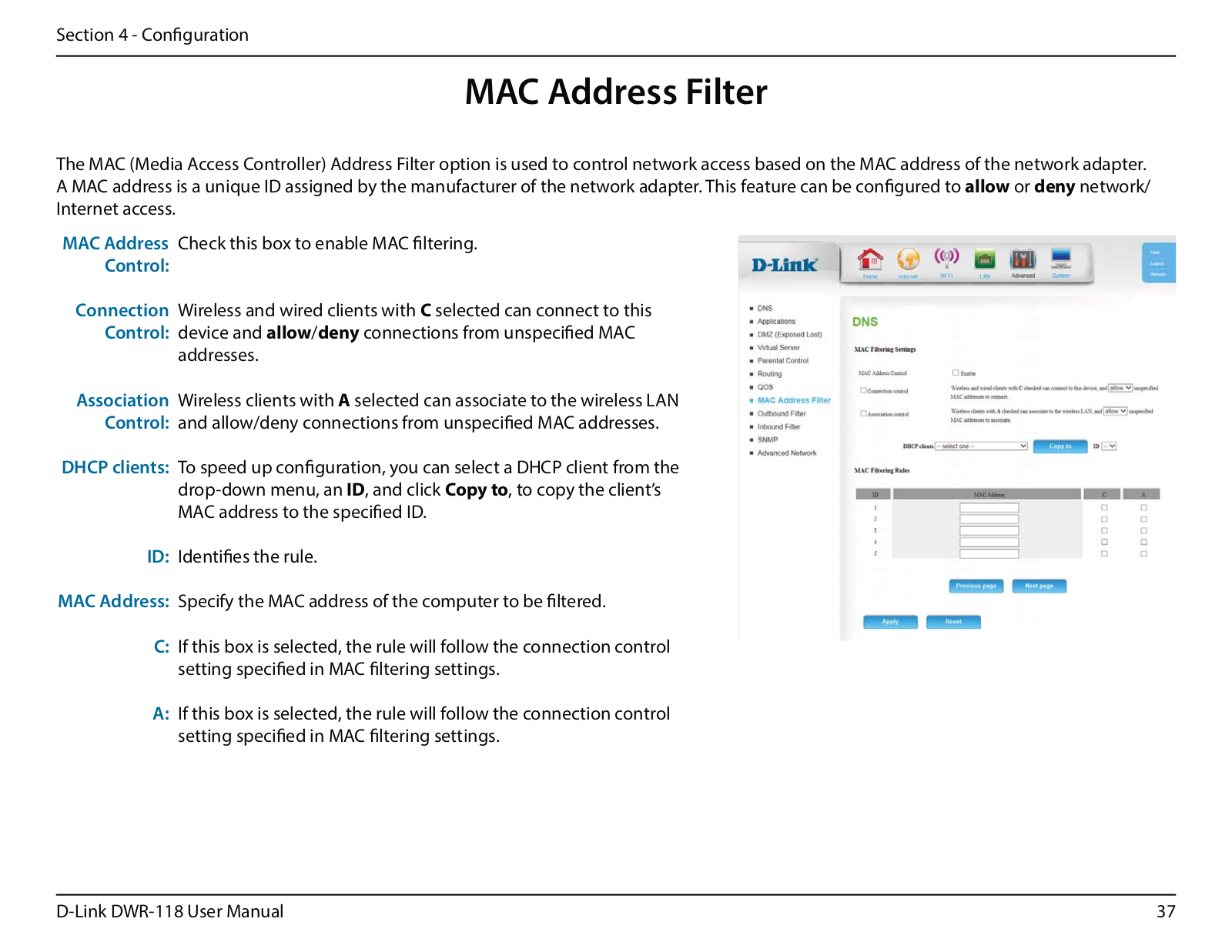
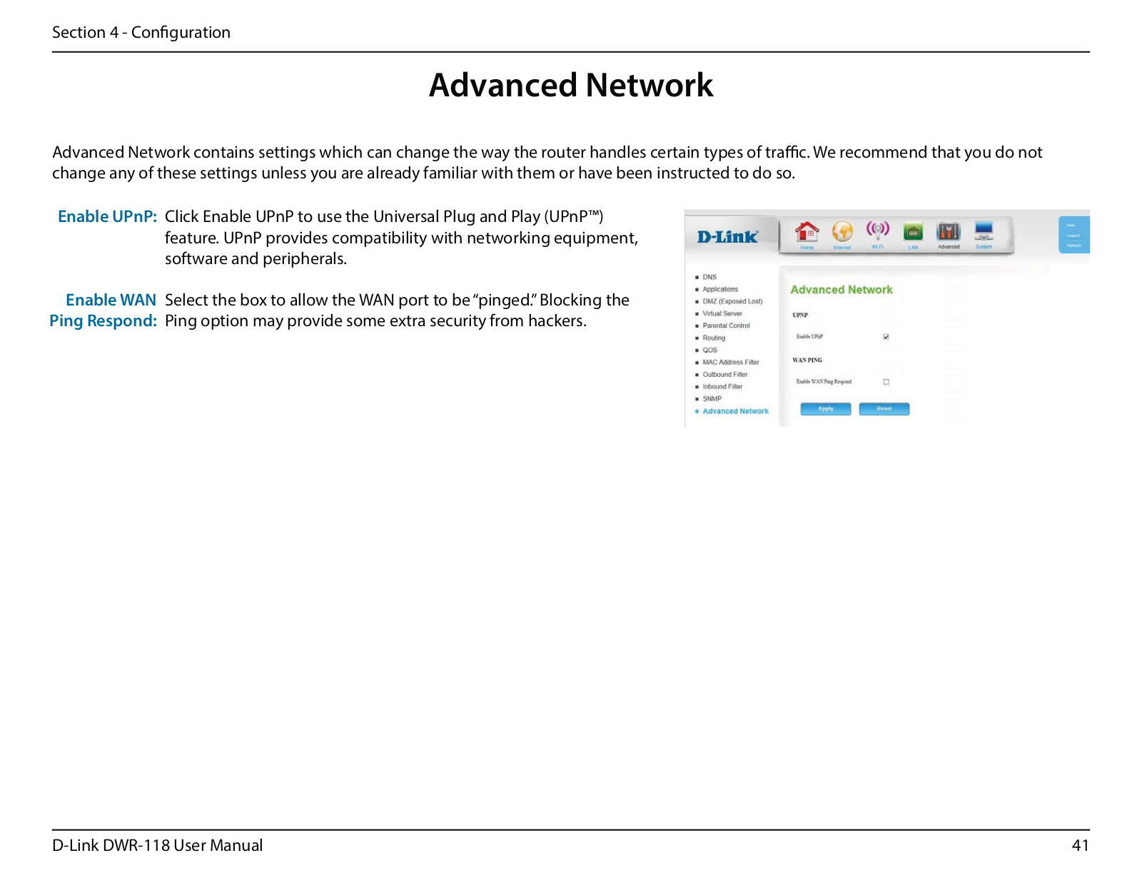
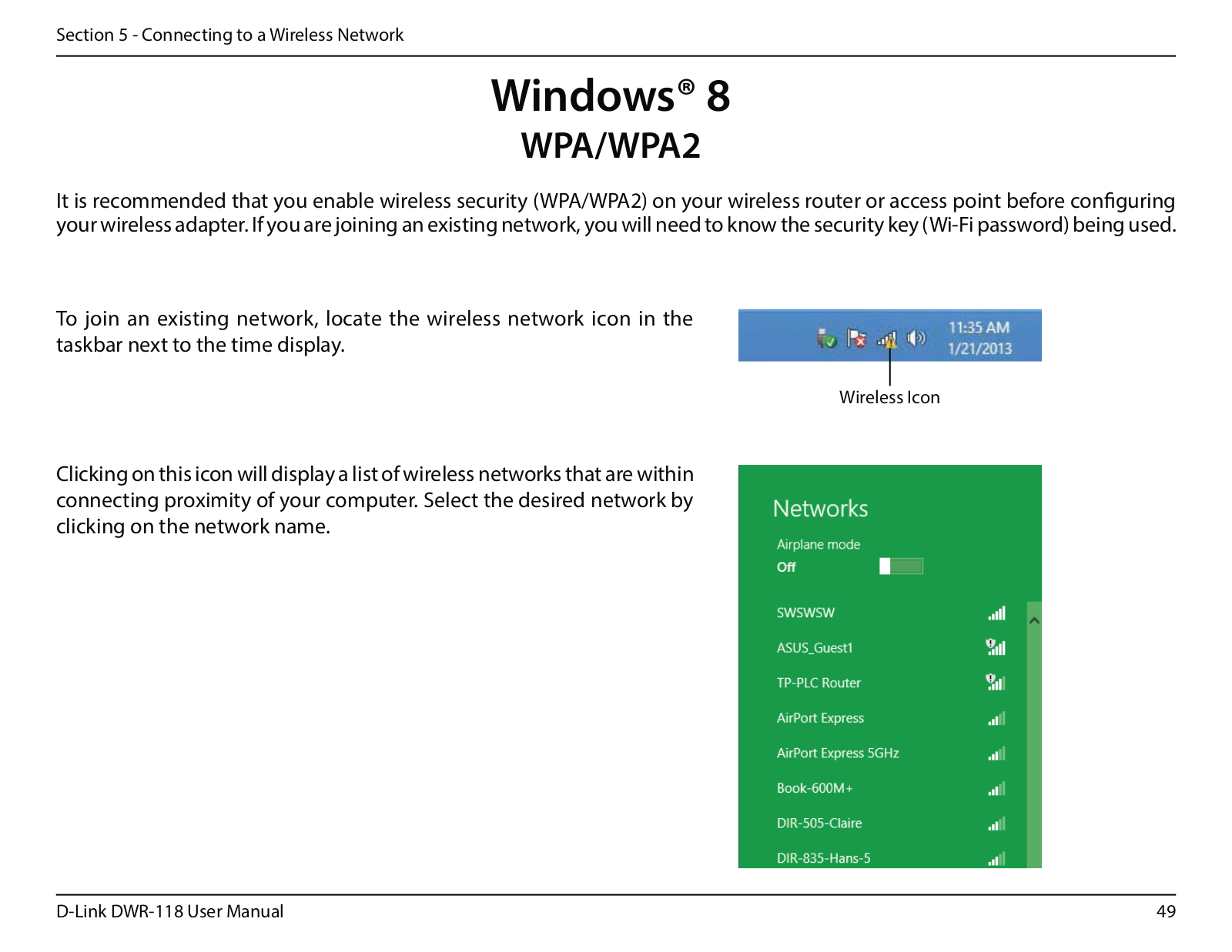
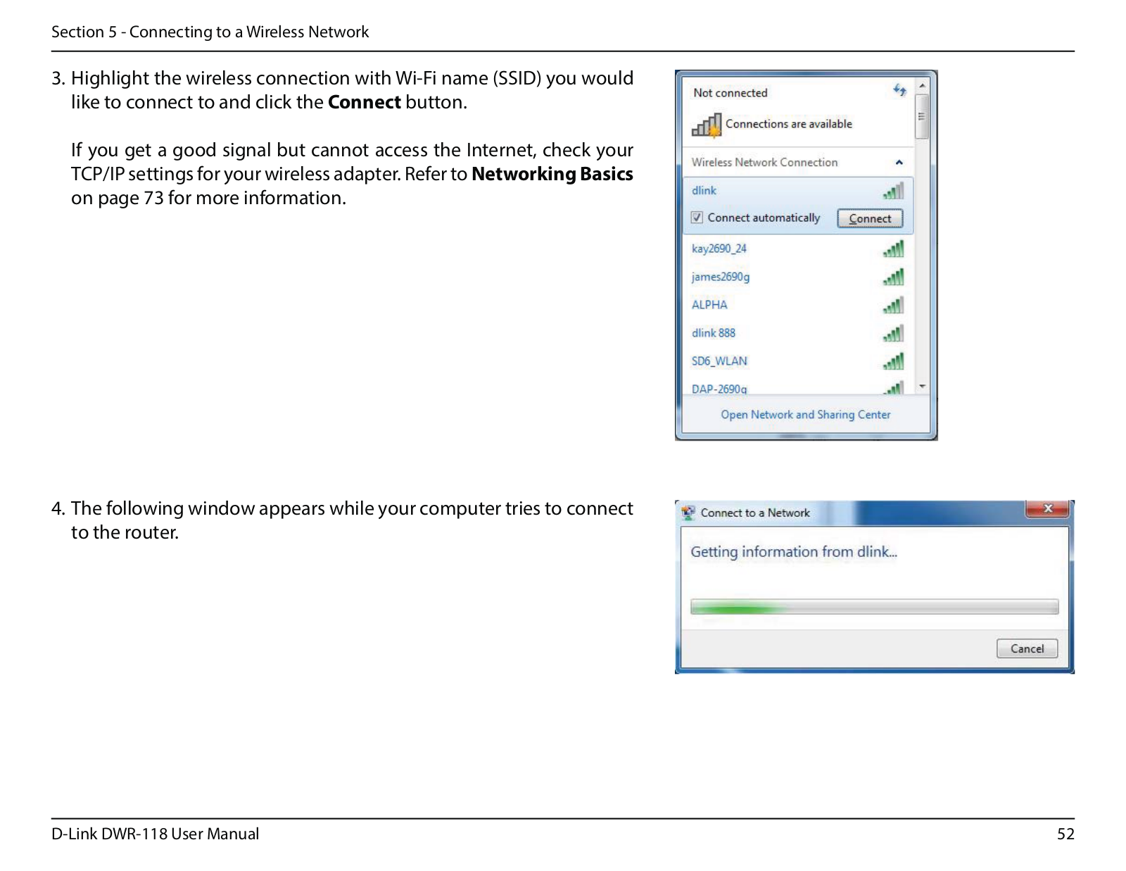
User Manual
Download
Loading...
+
hidden pages
Unhide
You need points to download manuals.
1 point = 1 manual.
You can buy points or you can get point for every manual you upload.
Buy points
Upload your manuals
 Loading...