

D Link WL3610APA1 User Manual
Quick Installation Guide
Unied AC Selectable Dual-Band
PoE Access Point
This document will guide you through the
basic installation process for your new
D-Link Unied Wireless Access Point.
DWL-3610AP
POWER
Documentation also available on
the CD and via the D-Link web site
WLAN
LAN
About This Guide
This installation guide provides basic
instructions for installing the DWL-3610AP Unied
AC Selectable Dual-band PoE Access Point on
ENGLISH
your network. For additional information about
how to use the Access Point, please see the User
Manual, which is available on the CD included in
this package or from the D-Link support website.
Optional Accessories
- PoE Base Unit (Model: DPE-101GI)
Note: These accessories are not included in
the package. If any of these items are required,
please contact your reseller to order it.
Hardware Overview
System Requirements
- CD-ROM Drive
- Windows
®
, Macintosh®, or Linux-based
operating system
- Ethernet port or installed Ethernet adapter
- Internet Explorer 7.0, Safari 5.0, Firefox 4.0,
or higher
Unpacking the Product
Open the shipping carton and carefully unpack its
contents. Please consult the packing list located
in following information to make sure all items are
present and undamaged. If any item is missing
or damaged, please contact your local D-Link
reseller for replacement.
- DWL-3610AP Unied AC Selectable Dual-band
PoE Access Point
- Power Adapter*
- Mounting Ring
- Console Cable*
- CD-ROM
- Ceiling Bracket (3 sets, sizes are 9/16", 14/16",
and 1 1/2")
*The power adapter is an optional accessory and not
included in the package in some regions. To power
the units use a D-Link PoE switch or the D-Link
DPE-101GI PoE injector.
*The console cable is an optional accessory and
not included in the package in Armenia, Azerbaijan,
Belarus, Georgia, Israel, Kaliningrad, Kazakhstan,
Kyrgyzstan, Latvia, Lithuania, Moldova, Mongolia,
Russia, Turkey, Turkmenistan, Ukraine, and
Uzbekistan. If a cable is required, please contact your
reseller to order it (Model: ACS-AP-CONSOLE).
2 D-Link DWL-3610AP Quick Install Guide2 D-Link DWL-3610AP Quick Install Guide
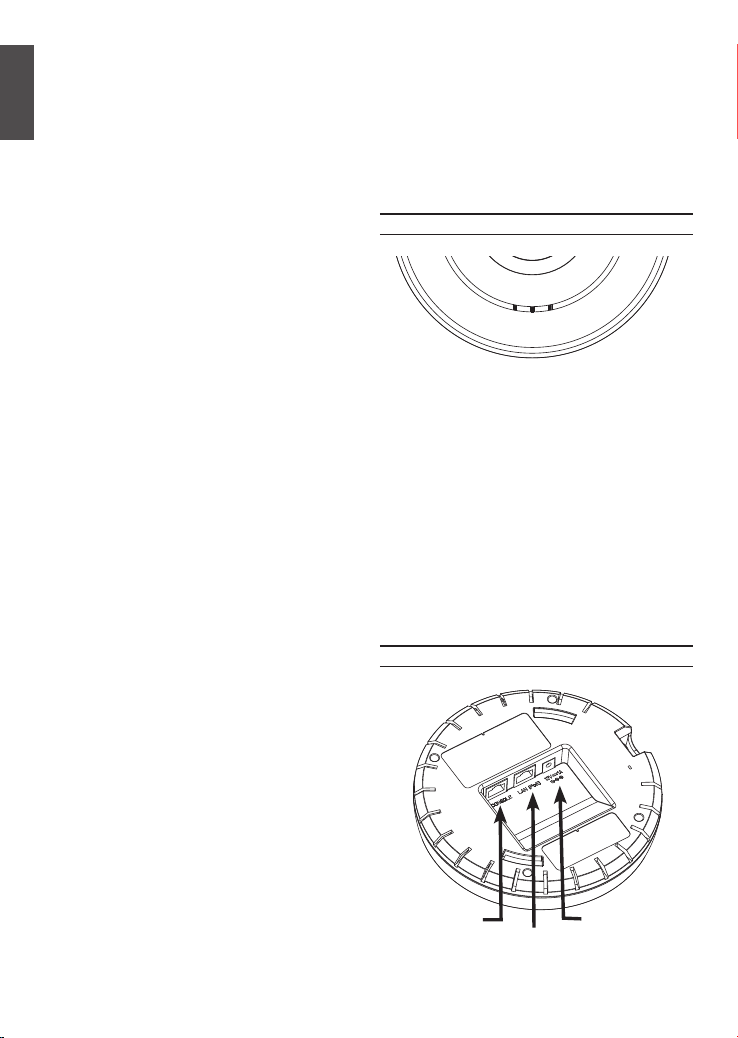
LEDs
POWER
WLAN
LAN
Figure 1. DWL-3610AP LEDs
WLAN – When the LED is lit up, the access
LAN – When this LED is lit up, the device’s
POWER – When the LED is lit up, the access
point’s radio is enabled. It will blink
when there is wireless trafc. When
the LED color is Amber, it is working
on 2.4GHz. When the color is Green, it
is working on 5GHz.
Ethernet port is connected to an active
router or switch. The light will blink
when there is trafc going through the
port.
point is powered and ready for use.
Interfaces
Console Port
LAN Port (PoE)
Figure 2. DWL-3610AP Rear Panel
Power Receptor
ComputerDWL-3610AP
ComputerDWL-3610AP
ComputerDWL-3610AP
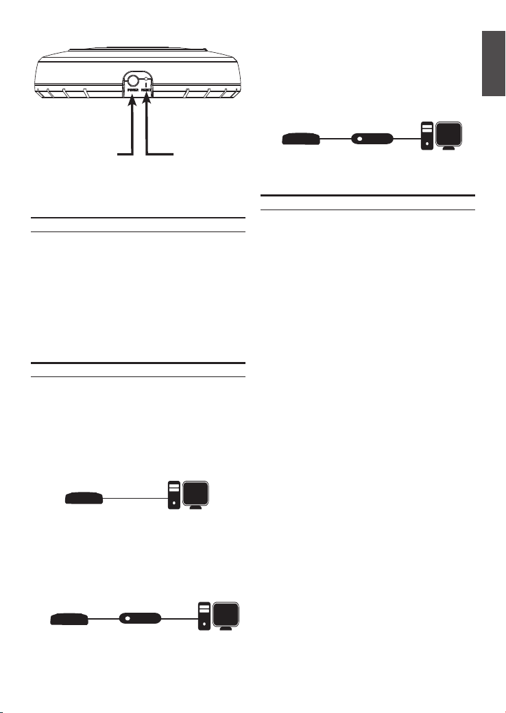
• Manage the access point from the computer
ComputerDWL-3610AP
ComputerDWL-3610AP
via the Unied Wireless Switch or Wireless
Controller: Connect the access point to
a Unied Wireless Switch or Wireless
Controller. Connect your computer to the
same network as that of the Unied Wireless
Switch or Wireless Controller.
ENGLISH
Power Button
Reset Button
(For Power Adapter)
Installation
Power on the access point
To power on the DWL-3610AP, you can use ONE of
the following methods:
1. Connect the supplied power adapter
OR
2. Plug one end of an Ethernet cable into the LAN
port of the DWL-3610AP and the other end into
a port on a PoE switch.
Congure the access point
To set up and manage the DWL-3610AP, use one
of the following methods:
• Manage the access point from the computer:
Connect the access point and your computer
directly via a straight-through Ethernet cable.
• Manage the access point from the computer
via the Switch or Router: Connect the
access point and your computer to the same
switch or router.
Unied Wireless Switch
or
Wireless Controller
Mounting Options
You can mount a DWL-3610AP access point on any
of the following types of surfaces:
• Solid surface wall or ceiling
• Tabletop
Cable Requirement
Use a CAT 5 cable with an even sheath.
The Ethernet ports on the DWL-3610AP access
point cannot accept a CAT 5 cable that has an
uneven sheath; the RJ-45 connector on the cable
will not fit properly into the receptacle on the access
point.
Wall Installation Recommendations
If you plan to install the DWL-3610AP on a wall or
other vertical surfaces, orient the top of the access
point (the side with the LEDs) toward the intended
coverage area. The radio antennas transmit through
the top of the access point but not through the
bottom (where the bracket is).
Warning: The DWL-3610AP is designed to
receive PoE power only from an 802.3af-compliant
source, or from a D-Link-approved power injector.
Connecting an access point to a Power over
Ethernet (PoE) device that is not approved by
D-Link can damage the equipment.
Switch or Router
D-Link DWL-3610AP Quick Install Guide 3D-Link DWL-3610AP Quick Install Guide 3
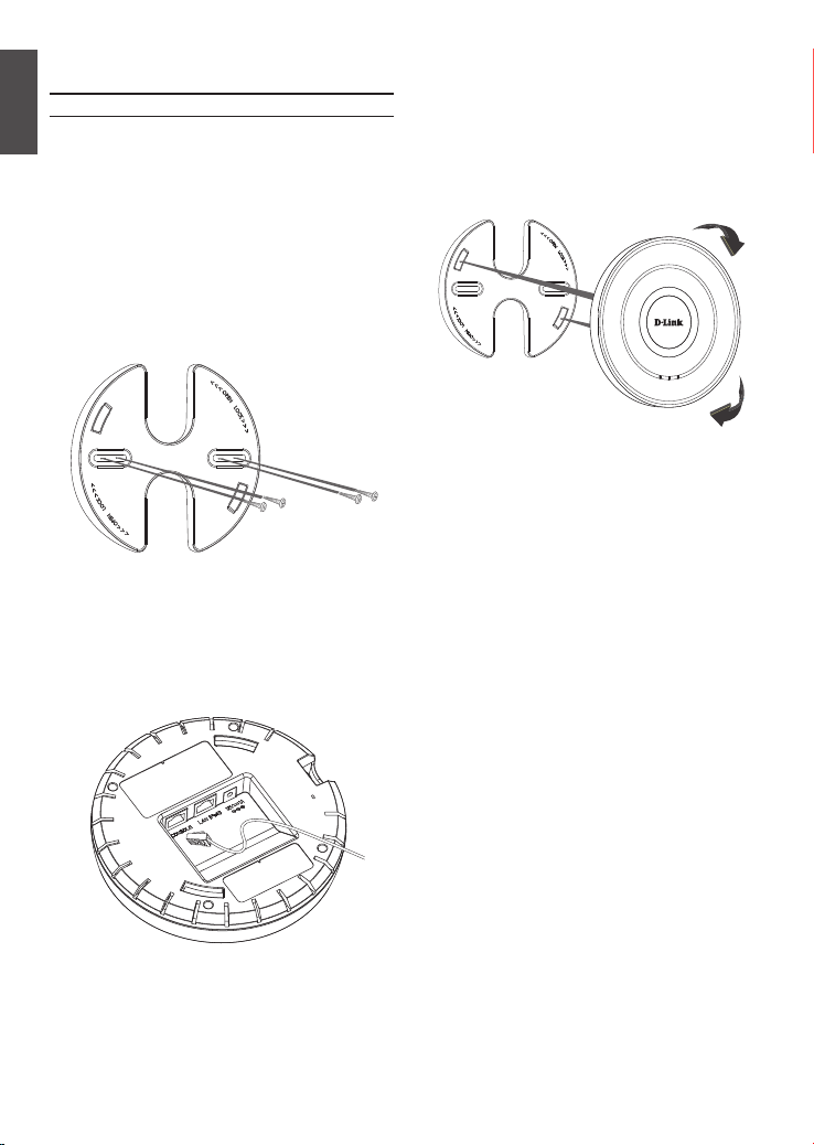
Mounting Using Anchor Screws
Installation
ENGLISH
1. Place the plastic wall mounting ring on a
wall or ceiling.
2. Mark the points where you will insert the
screws. Take out the mounting ring.
3. Drill holes in the marked points and
insert the plastic wall anchors.
4. Use the supplied screws to attach the
mounting ring to the wall.
5. Plug the CAT 5 cable into the LAN port on
the access point.
6. To attach the access point to the
mounting ring, rst locate the right side
of the access point that has a small lock
symbol on it, and make sure to line up
this side with the side of the mounting
ring that has Open - Lock written on it.
POWER
2.4GHz
LAN
7. Twist clockwise to lock the access point
onto the ring. The lock symbol on the
access point must point directly to the
Close text on the mounting ring.
4 D-Link DWL-3610AP Quick Install Guide4 D-Link DWL-3610AP Quick Install Guide

Mounting Using Ceiling Bracket
Installation
1. Clip two ceiling brackets on the ceiling
panels. Make sure both bracket are
parallel.
Ceiling crossbar
Ceiling bracket
2. Use the provided screws to attach the
mounting ring to the ceiling bracket.
3. Plug the CAT 5 cable into the LAN port on
the access point.
4. Placed the DWL-3610AP’s male bracket
in the mounting ring’s female bracket.
Rotate the product clockwise to lock it in
position.
ENGLISH
LAN
2.4GHz
POWER
D-Link DWL-3610AP Quick Install Guide 5D-Link DWL-3610AP Quick Install Guide 5

Regulatory Information
ErP Power Usage
This device is an Energy Related Product (ErP) with High Network Availability (HiNA), and automatically
switches to a power-saving Network Standby mode within 1 minute of no packets being transmitted. It
can also be turned off through a power switch to save energy when it is not needed.
Network Standby: 6.2063 watts
Switched Off: 0.056 watts
Federal Communication Commission Interference Statement
This equipment has been tested and found to comply with the limits for a Class B digital device, pursuant
to Part 15 of the FCC Rules. These limits are designed to provide reasonable protection against harmful
interference in a residential installation. This equipment generates, uses and can radiate radio frequency energy
and, if not installed and used in accordance with the instructions, may cause harmful interference to radio
communications. However, there is no guarantee that interference will not occur in a particular installation.
If this equipment does cause harmful interference to radio or television reception, which can be determined
by turning the equipment o and on, the user is encouraged to try to correct the interference by one of the
following measures:
- Reorient or relocate the receiving antenna.
- Increase the separation between the equipment and receiver.
- Connect the equipment into an outlet on a circuit dierent from that to which the receiver is
connected.
- Consult the dealer or an experienced radio/TV technician for help.
Non-modications Statement:
Any changes or modications not expressly approved by the party responsible for compliance could void the
user’s authority to operate this equipment.
Caution:
This device complies with Part 15 of the FCC Rules. Operation is subject to the following two conditions:
(1) This device may not cause harmful interference, and (2) this device must accept any interference
received, including interference that may cause undesired operation.
6 D-Link DWL-3610AP Quick Install Guide

RF Frequency Requirements
This device is for indoor use only when using all channels in the
5.150 GHz - 5.250 GHz, 5.250 GHz - 5.350 GHz, 5.470 GHz - 5.725 GHz, 5.725 GHz - 5.850 GHz
frequency range. High power radars are allocated as primary users of the
5.150 GHz - 5.250 GHz, 5.250 GHz - 5.350 GHz, 5.470 GHz - 5.725 GHz, 5.725 GHz - 5.850 GHz
bands. These radar stations can cause interference with and/or damage this device. This device will not
operate on channels which overlap the 5600-5650 MHz band.
It is restricted to indoor environments only.
IMPORTANT NOTICE:
FCC Radiation Exposure Statement
This equipment complies with FCC radiation exposure limits set forth for an uncontrolled environment. This
equipment should be installed and operated with minimum distance 20 cm between the radiator and your
body.
Innovation, Science and Economic Development Canada (ISED)
Statement:
This Class B digital apparatus complies with Canadian ICES-003.
Cet appareil numérique de la classe B est conforme à la norme NMB-003 du Canada.
Innovation, Science and Economic Development Canada (ISED)
Statement:
This device complies with ISED licence-exempt RSS standard(s). Operation is subject to the following two
conditions:
(1) this device may not cause interference, and
(2) this device must accept any interference, including interference that may cause undesired
operation of the device.
Le présent appareil est conforme aux CNR d'ISED applicables aux appareils radio exempts de licence.
L'exploitation est autorisée aux deux conditions suivantes :
(1) l'appareil ne doit pas produire de brouillage, et
(2) l'utilisateur de l'appareil doit accepter tout brouillage radioélectrique subi, même si le brouillage
est susceptible d'en compromettre le fonctionnement.
(i) the device for operation in the band 5150-5250 MHz is only for indoor use to reduce the potential for
harmful interference to co-channel mobile satellite systems;
(i) les dispositifs fonctionnant dans la bande 5150-5250 MHz sont réservés uniquement pour une utilisation à
l’intérieur an de réduire les risques de brouillage préjudiciable aux systèmes de satellites mobiles utilisant les
mêmes canaux;
D-Link DWL-3610AP Quick Install Guide 7
(iv) the worst-case tilt angle(s) necessary to remain compliant with the e.i.r.p. elevation mask requirement set
forth in Section 6.2.2(3) shall be clearly indicated.
(iv) les pires angles d'inclinaison nécessaires pour rester conforme à l'exigence de la p.i.r.e.applicable au masque
d'élévation, et énoncée à la section 6.2.2(3), doivent être clairement indiqués.
Operations in the 5.25-5.35 GHz band are restricted to indoor usage only.
Les opérations dans la bande de 5.25-5.35 GHz sont limités à un usage intérieur seulement.
Radiation Exposure Statement
This equipment complies with ISED radiation exposure limits set forth for an uncontrolled environment. This
equipment should be installed and operated with minimum distance 20 cm between the radiator and your
body.
Déclaration d'exposition aux radiations
Cet équipement est conforme aux limites d'exposition aux rayonnements ISED établies pour un environnement
non contrôlé. Cet équipement doit être installé et utilisé avec un minimum de 20 cm de distance entre la
source de rayonnement et votre corps.
NCC
警 語:
以下警語適用台灣地區
依據 低功率電波輻射性電機管理辦法
第十二條: 經型式認證合格之低功率射頻電機,非經許可,公司、商號或使用者均不得擅自變更頻率、加
大功率或變更原設計之特性及功能。
第十四條: 低功率射頻電機之使用不得影響飛航安全及干擾合法通信;經發現有干擾現象時,應立即停
用,並改善至無干擾時方得繼續使用。前項合法通信,指依電信法規定作業之無線電通信。低功率射頻電
機須忍受合法通信或工業、科學及醫療用電波輻射性電機設備之干擾。
無線傳輸設備 (UNII)
在 5.25-5.35 秭赫頻帶內操作之無線資訊傳輸設備,限於室內使用。無線資訊傳輸設備忍受合法通信之干
擾且不得干擾合法通信;如造成干擾,應立即停用,俟無干擾之虞,始得繼續使用。無線資訊傳設備的製
造廠商應確保頻率穩定性,如依製造廠商使用手冊上所述正常操作,發射的信號應維持於操作頻帶中。
電磁波曝露量MPE標準值(MPE) 1mW/cm2 , 送測產品實值為0.3331 mW/cm2 , 本產品建議應距離人體20 cm
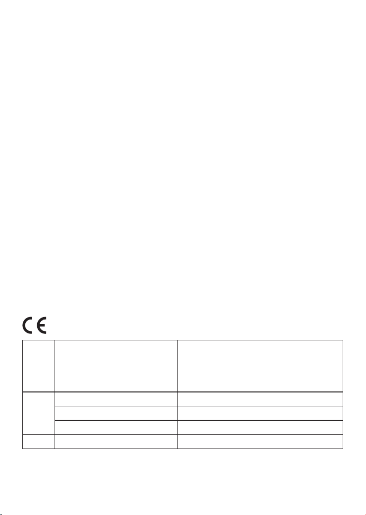
Frequency Band(s)
Frequenzband
Fréquence bande(s)
Bandas de Frecuencia
Frequenza/e
Frequentie(s)
5.15 – 5.25 GHz 200 mW
5 G
2.4 G 2.4 – 2.4835 GHz 100 mW
8 D-Link DWL-3610AP Quick Install Guide
5.25 – 5.35 GHz 200 mW
5.47 – 5.725 GHz 1 W
Max. Output Power (EIRP)
Max. Output Power
Consommation d’énergie max.
Potencia máxima de Salida
Potenza max. Output
Max. Output Power
 Loading...