

Page 1

RG-S8600 Series Switch
Hardware Installation and Reference Guide V1.78
Page 2

Copyright statement
Ruijie Networks©2000-2014
Ruijie Networks reserves all copyrights of this document. Any reproduction, excerption, backup, modification, transmission, translation
or commercial use of this document or any portion of this document, in any form or by any means, without the prior written consent of
Ruijie Networks is prohibited.
, , , , , ,
, , ,
, , are registered trademarks of Ruijie Networks. Counterfeit is
strictly prohibited.
Exemption statement
This document is provided “as is”. The contents of this document are subject to change without any notice. Please obtain the latest
information through the Ruijie Networks website. Ruijie Networks endeavors to ensure content accuracy and will not shoulder any
responsibility for losses and damages caused due to content omissions, inaccuracies or errors.
Page 3
Preface
Thank you for using our products. This manual will guide you through the installation of the switch.
Scope
It is intended for the users who have some experience in installing and maintaining network hardware. At the same time, it
is assumed that the users are already familiar with the related terms and concepts.
Obtaining Technical Assistance
Ruijie Networks website: http://www.ruijienetworks.com
Online customer services: http://webchat.ruijie.com.cn
Customer service center: http://www.ruijie.com.cn/service.aspx
Customer services hotline: +86-4008-111-000
BBS: http://support.ruijie.com.cn
Customer services email: service@ruijie.com.cn
Related Documents
Documents
Description
Configuration Guide
Describes network protocols and related mechanisms that supported by the
product, with configuration examples.
Command Reference
Describes the related configuration commands, including command modes,
parameter descriptions, usage guides, and related examples.
Documentation Conventions
The symbols used in this document are described as below:
This symbol draws the attention of readers to some suggestions and references.
This symbol reminds readers to be alert of wrong operations that may lead to loss of data or damage to equipment.
Page 4

Chapter 1 Product Overview
The RG-8600 switch is a module-based high-density multi-service IPv6 10Gbp score routing switch developed by Ruijie
Networks, providing powerful defense capability based on high performance and capacity. It can be expanded according
to users’ business needs, satisfying the design requirements for putting equal emphasis on service and performance.
The RG-S8600 switch provides dual management boards and dual power supplies for redundancy. Currently four models
are available:
The RG-S8614: designed with 14 transverse slots, supporting dual management engine modules, providing 12 slots
for service modules.
The RG-S8610: designed with 10 vertical slots, supporting dual management engine modules and providing eight
slots for service modules.
The RG-S8606: designed with six transverse slots, supporting dual management engine modules and providing four
slots for service modules.
The RG-S8606 B: designed with six transverse slots, supporting dual management engine modules and providing
four slots for service modules.
RG-S8614
The RG-8600 switch is an A-class product and may cause radio disturbance to surroundings. In this case, users are
advised to take proper measures against the disturbance.
Specifications
Model
RG-S8614
Module Slot
14 (two for management engine modules)
Module Type
M8614-CM II
M8600-24SFP/12GT
M8600-24GT/12SFP
M8600P-24GT/12SFP
M8600-02XFP
M8600-48GT/4SFP
M8600P-48GT/4SFP
M8600-04XFP
M8600-24SFP
M8600-MPLS
M8600-NMM
M8600-02XFP24SFP/12GT-E
M8600-08XFP
M8600-VSU-02XFP
M8600-FW
RG-WALL 1600-B-E
RG-WALL 1600-B-U
RG-WALL 1600 FW Module
M8600-WS
M8600-02XFP24SFP/12GT-EC
M8600-24SFP/12GT-EC
M8600-48GT/4SFP-EC
M8600P-48GT/4SFP-EC
M8600-24GT/12SFP-EC
M8600-04XFP-EC
M8600-04QXS-DA
M8600-16XS-DA
Hot Swapping
Supported
Management
Redundancy
Supported
Page 5

Power Supply
RG-PA1200:90 ~ 264VAC, 47 ~ 63Hz, power: 1200W
RG-PA1200E: 90 ~ 264VAC, 47 ~ 63Hz, power: 1200W
RG-PA2000: 90 ~ 176VAC, 47 ~ 63Hz, power: 1200W
176 ~ 264VAC, 47 ~ 63Hz, power: 2000W
RG-PA1200I: 90 ~ 176VAC, 47 ~ 63Hz, power: 530W
176 ~ 264VAC, 47 ~ 63Hz, power: 1400W
RG-PA2000I: 90 ~ 176VAC, 47 ~ 63Hz, power: 1080W
176 ~ 264VAC, 47 ~ 63Hz, power: 2000W
RG-PD1200: -36 ~ -72VDC, power: 1200W
RG-PD2000: -36 ~ -72VDC, power: 2000W
PA stands for AC power; PD stands for DC power.
Power Supply
Redundancy
The power supply redundancy of the same model is supported
Fan
GB9254-2008
EMC Standards
GB4943-2011
Safety
Standards
GB4943-2011
Operating
Temperature
0 ~ 40°C
Storage
Temperature
-40 ~ 70°C
Operating
Humidity
10% ~ 90% RH (non-condensing)
Earthquake
Resistance
Able to resist the earthquake intensity 9
Weight
≤114 kg
Dimensions
(W x D x H)
436.8 mm x 508 mm x 932.2 mm, 21 RU
Product Appearance
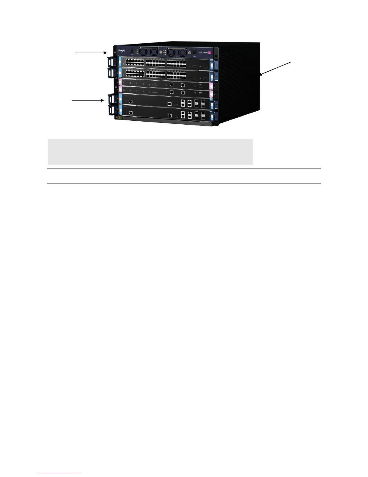
Figure 1-1 Appearance of the RG-S8614 Switch
Page 6
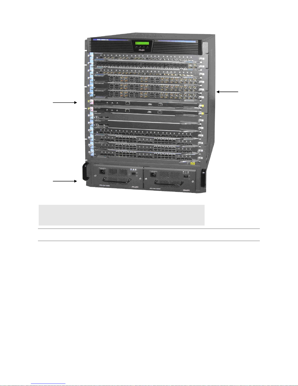
Note:
Modular layer: offers up to 14 module slots
Power layer: supports up to two AC or DC power supplies
Air outlet: Located in the back of the chassis, as the air-outlet unit of the
system.
The RG-S8614 switch’s hardware system is composed of the chassis, the power system, modules, the fan tray and
the air filter.
Chassis
The RG-S8614 switch has a standard 19-inch chassis, which is 932.2mm high, 436.8mm wide and 508mm deep. It
consists of the system modular layer, the fan layer, the air filter and the power system layer.
The system modular layer is a module subrack that mechanically supports various modules of the RG-S8614.The
modular subrack is composed of module slots and back panel.
At the bottom of the chassis are two power frames. The air filter is located on the right side of the module subrack of the
chassis, facing the front of the chassis. On the back of the module subrack is the fan layer, which houses ten fans working
to suction air.
Module Slot
The RG-S8614 switch provides 14 module slots, of which two in the middle are only for the management modules. The 12
slots on the top and the bottom can accommodate a mix of various modules. Modules are inserted horizontally, with the
same height of 412 mm, and depth of 350 mm.
When all the slots are occupied, the modules in the subrack of the RG-S8614 switch are configured as follows:
Two management modules as backup for each other
12 modules are selected according to needs
The slots for the two management modules are in the middle and identified as M1 and M2 from bottom to top; the other 12
line cards are numbered 1-12 from bottom to top.
Page 7

Backplane
The RG-S8614 switch’s backplane interconnects high-speed data links from switch management board to module circuit
board and various management and control signals between modules. Its functions are as follows:
Interconnects all signals between modules and provide high-speed communication channel.
Passive backplane
Supports active/standby switching between management modules
Supports automatic identification of various slots
Implements distributed power supply
Introduces monitoring signal lines of the fan and power supply
Ventilation and Heat Dissipation System
The operating temperature of the RG-S8614 switch is 0 to 40°C. The thermal design must ensure that the surface
temperature of the components does not exceed 50% to 80% of the allowed maximum temperature and satisfy the
requirement on the device’s reliability in the temperature range while ensuring the device’s reliability, safety and
maintainability. According to the thermal design of the RG-S8614 switch, fans are used to draw air for forced convection
cooling in order to ensure that the device works properly in the specified environment.
Page 8

Figure 1-2 Ventilation and Heat Dissipation System of the RG-S8614 Switch
This structure is designed with air inlet on two sides, and air outlet at the back. The air flow direction is shown above.
Ten 120 x 120 x 38 fans are used to blow air outside for convection and ultimately heat dissipation. The chassis
should be mounted in a place with sufficient space for air circulation. Sufficient space (10 cm at least) must be
reserved at the air intakes and exhaust vents for ventilation.
RG-S8610
The RG-8600 series is an A-class product and may cause radio disturbance to surroundings. In this case, users are
advised to take proper measures against the disturbance.
Specifications
Model
RG-S8610
Module Slot
10 (two for management engine modules)
Page 9

Module Type
M8610-CM
M8610-CM II
M8610-CM III
M8610-CM II LITE
M8600-24SFP/12GT
M8600-24GT/12SFP
M8600P-24GT/12SFP
M8600-02XFP
M8600-48GT/4SFP
M8600P-48GT/4SFP
M8600-04XFP
M8600-24SFP
M8600-MPLS
M8600-NMM
M8600-02XFP24SFP/12GT-E
M8600-08XFP
M8600-VSU-02XFP
M8600-FW
RG-WALL 1600-B-E
RG-WALL 1600-B-U
RG-WALL 1600 FW Module
M8600-WS
M8600-02XFP24SFP/12GT-EC
M8600-24SFP/12GT-EC
M8600-48GT/4SFP-EC
M8600P-48GT/4SFP-EC
M8600-24GT/12SFP-EC
M8600-04XFP-EC
M8600-04QXS-DA
M8600-16XS-DA
Hot Swapping
Supported
Management Redundancy
Supported
Power Supply
RG-PA1200: 90 ~ 264VAC, 47 ~ 63Hz, power: 1200W
RG-PA1200E: 90 ~ 264VAC, 47 ~ 63Hz, power: 1200W
RG-PA2000: 90 ~ 176VAC, 47 ~ 63Hz, power: 1200W
176 ~ 264VAC, 47 ~ 63Hz, power: 2000W
RG-PA1200I: 90 ~ 176VAC, 47 ~ 63Hz, power: 530W
176 ~ 264VAC, 47 ~ 63Hz, power: 1400W
RG-PA2000I: 90 ~ 176VAC, 47 ~ 63Hz, power: 1080W
176 ~ 264VAC, 47 ~ 63Hz, power: 2000W
RG-PD1200: -36 ~ -72VDC, power: 1200W
RG-PD2000: -36 ~ -72VDC, power: 2000W
PA stands for AC power; PD stands for DC power.
Power Supply Redundancy
The Power supply redundancy of the same model is supported
Fan
M8610-FAN (supporting hot swapping and fault alarming)
Environmental
EMC
Standards
GB9254-2008
Safety
Standards
GB4943-2011
Operating
Temperature
0 ~ 40°C
Storage
Temperature
-40 ~ 70°C
Operating
Humidity
10% ~ 90% RH (non-condensing)
Earthquake
Resistance
Able to resist the earthquake intensity 9
Weight
≤93 kg
Dimensions
(W x D x H)
436.8 mm x 448 mm x 956 mm, 21.5 RU
Page 10

Product Appearance
Figure 1-3 Appearance of the RG-S8610 Switch
Note:
Air outlet layer: the air outlet layer of the whole system, discharge air to the
outside on three sides
Fan tray: slot of the fan tray, the active heat dissipation unit of the system
Modular layer: provides 10 vertical module slots, can house modules with
different functions
Wiring layer: arranges and leads out various cables in good order while
preventing the drooping cables from blocking the air inlet
Air inlet layer: inducts air into the chassis as the airway of the whole heat
dissipation unit;
Power layer: supports up to two AC or DC power supplies
Page 11

The RG-S8610’s hardware system is composed of the chassis, the power system, modules, the cable management
bracket, the fan tray, air inlet/outlet ducts and the air filter.
Chassis
The RG-S8614 has a standard 19-inch chassis, which is 956mm high, 436.8mm wide and 448mm deep. It consists of the
system modular layer, the fan layer, air inlet/outlet layers, the cable management bracket, the air filter and the power
system layer.
The system modular layer is a module subrack that mechanically supports various modules of the RG-S8610.The
modular subrack is composed of module slots and back panel.
At the bottom of the chassis are two power frames, above which is the air inlet layer. The air filter is located between the
air inlet layer and the cable management bracket, which is located below the system modular layer. Above the system
modular layer is the fan layer, which houses six fans. At the top of the chassis is the air outlet layer working to suction air.
Module Slot
RG-S8610 provides 10 module slots, of which two in the middle are only for the MCs. The eight slots on the left and the
right sides can accommodate a mix of various modules. Modules are inserted vertically in RG-S8610, with the same
height of 412 mm, and depth of 350 mm.
When all the slots are occupied, the modules in the subrack of RG-S8610 are arranged as follows:
Two management modules as backup for each other
Eight modules selected according to needs
The slots for the two management modules are in the middle and identified as M1 and M2 from left to right; the other eight
line cards are numbered 1-8 from left to right.
Backplane
The RG-S8610’s backplane interconnects high-speed data links from switch management board to module circuit board
and various management and control signals between modules. Its functions are as follows:
Interconnects all signals between modules and provide high-speed communication channel.
Passive backplane
Supports active/standby switching between management modules
Supports automatic identification of various slots
Implements distributed power supply
Introduces monitoring signal lines of the fan and power supply
Ventilation and Heat Dissipation System
The operating temperature of RG-S8610 is 0 to 40°C. The thermal design must ensure that the surface temperature of the
components does not exceed 50% to 80% of the allowed maximum temperature and satisfy the requirement on the
device’s reliability in the temperature range while ensuring the device’s reliability, safety and maintainability. According to
the thermal design of RG-S8610, fans are used to draw air for forced convection cooling in order to ensure that the device
works properly in the specified environment.
Page 12
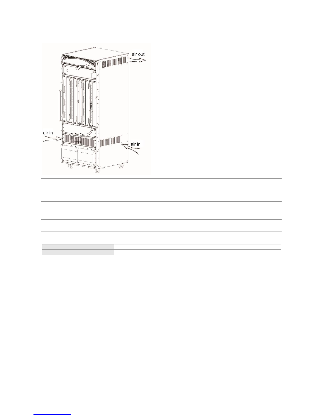
Figure 1-4 Ventilation and Heat Dissipation System of the RG-S8610 Switch
This structure is designed with air inlet at the front and back and on both sides, and air outlet at the back and on both
sides. The air flow direction is shown above. Six 120 x 120 x 38 fans are used to blow air outside for convection and
ultimately heat dissipation. The chassis should be mounted in a place with sufficient space for air circulation.
Sufficient space (10 cm at least) must be reserved at the air intakes and exhaust vents for ventilation.
RG-S8606
The RG-8600 series is an A-class product and may cause radio disturbance to surroundings. In this case, users are
advised to take proper measures against the disturbance.
Specifications
Model
RG-S8606
Module Slot
Six (two for management engine modules)
Page 13
Module Type
M8606-CM
M8606-CM II
M8606-CM III
M8606-CM II LITE
M8600-24SFP/12GT
M8600-24GT/12SFP
M8600P-24GT/12SFP
M8600-02XFP
M8600-48GT/4SFP
M8600P-48GT/4SFP
M8600-04XFP
M8600-24SFP
M8600-MPLS
M8600-NMM
M8600-02XFP24SFP/12GT-E
M8600-08XFP
M8600-VSU-02XFP
M8600-FW
RG-WALL 1600-B-E
RG-WALL 1600-B-U
RG-WALL 1600 FW Module
M8600-WS
M8600-02XFP24SFP/12GT-EC
M8600-24SFP/12GT-EC
M8600-48GT/4SFP-EC
M8600P-48GT/4SFP-EC
M8600-24GT/12SFP-EC
M8600-04XFP-EC
Hot Swapping
Supported
Management Redundancy
Supported
Power Supply
RG-PA1200: 90 ~ 264VAC, 47 ~ 63Hz, power: 1200W
RG-PA1200E: 90 ~ 264VAC, 47 ~ 63Hz, power: 1200W
RG-PA2000: 90 ~ 176VAC, 47 ~ 63Hz, power: 1200W
176 ~ 264VAC, 47 ~ 63Hz, power: 2000W
RG-PA1200I: 90 ~ 176VAC, 47 ~ 63Hz, power: 530W
176 ~ 264VAC, 47 ~ 63Hz, power: 1400W
RG-PA2000I: 90 ~ 176VAC, 47 ~ 63Hz, power: 1080W
176 ~ 264VAC, 47 ~ 63Hz, power: 2000W
RG-PD1200: -36 ~ -72VDC, power: 1200W
RG-PD2000:-36 ~ -72VDC, power: 2000W
PA stands for AC power; PD stands for DC power.
Power Supply Redundancy
The Power supply redundancy of the same model is supported
Fan
M8606-FAN (supporting hot swapping and fault alarming)
Environmental
EMC Standards
GB9254-2008
Safety
Standards
GB4943-2011
Operating
Temperature
0 ~ 40°C
Storage
Temperature
-40 ~ 70°C
Operating
Humidity
10% ~ 90% RH (non-condensing)
Earthquake
Resistance
Able to resist the earthquake intensity 9
Weight
≤73 kg
Dimensions
(W x D x H)
436.8 mm x 508 mm x 647.4 mm, 14.5 RU
Page 14

Product Appearance
Figure 1-5 Appearance of the RG-S8606 Switch
Note:
Modular layer: offers up to six module slots
Power layer: supports up to two AC or DC power supplies
Air outlet: Locates in the back of the chassis, the air-outlet unit of the
system.
The RG-S8606’s hardware system is composed of the chassis, the power system, modules and the fan tray.
Chassis
The RG-S8614 has a standard 19-inch chassis, which is 674.4mm high, 436.8mm wide and 508mm deep. It the system
modular layer, the fan layer, the air filter and the power system layer.
The system modular layer is a module subrack that mechanically supports various modules of RG-S8606.The modular
subrack is composed of module slots and the backplane.
At the bottom of the chassis are two power supply frames. The fan layer is at the back of the module subrack and houses
six fans working to suction air.
Module Slot
The RG-S8606 provides six module slots, of which two in the middle are only for the MCs. The four slots on the top and
the bottom can accommodate a mix of various modules. Modules are inserted horizontally in the RG-S8606, with the
same height of 412 mm, and depth of 350 mm.
When all the slots are occupied, the modules in the subrack of RG-S8606 are arranged as follows:
Two management modules as backup for each other
Four modules selected according to needs
Page 15

The slots for the two management modules are in the middle and identified as M1 and M2 from bottom to top; the other
four line cards are numbered 1-4 from bottom to top.
Backplane
The RG-S8606’s backplane interconnects high-speed data links from switch management board to module circuit board
and various management and control signals between modules. Its functions are as follows:
Interconnects all signals between modules and provide high-speed communication channel.
Passive backplane
Supports active/standby switching between management modules
Supports automatic identification of various slots
Implements distributed power supply
Introduces monitoring signal lines of the fan and power supply
Ventilation and Heat Dissipation System
The operating temperature of RG-S8606 is 0 to 40°C. The thermal design must ensure that the surface temperature of the
components does not exceed 50% to 80% of the allowed maximum temperature and satisfy the requirement on the
device’s reliability in the temperature range while ensuring the device’s reliability, safety and maintainability.. According to
the thermal design of RG-S8606, fans are used to draw air for forced convection cooling in order to ensure that the device
works properly in the specified environment.
Figure 1-6 Ventilation and Heat Dissipation System of the RG-S8606 Switch
This structure is designed with air inlet through the front plane, and air outlet at the back. The air flow direction is
shown above. Six 120 x 120 x 38 fans are used to blow air outside for convection and ultimately heat dissipation. The
chassis should be mounted in a place with sufficient space for air circulation. Sufficient space (10 cm at least) must
be reserved at the air intakes and exhaust vents for ventilation.
RG-S8606 B
The RG-8600 series is an A-class product and may cause radio disturbance to living environment. In this case, users
are advised to take proper measures against the disturbance.
Specifications
Model
RG-S8606 B
Module Slot
Six (two for management engine modules)
Page 16
Module Type
M8606-CM II
M8606-CM III
M8606-CM II LITE
M8600-24SFP/12GT
M8600-24GT/12SFP
M8600P-24GT/12SFP
M8600-02XFP
M8600-48GT/4SFP
M8600P-48GT/4SFP
M8600-04XFP
M8600-24SFP
M8600-MPLS
M8600-NMM
M8600-02XFP24SFP/12GT-E
M8600-08XFP
M8600-VSU-02XFP
M8600-FW
RG-WALL 1600-B-E
RG-WALL 1600-B-U
RG-WALL 1600 FW Module
M8600-WS
M8600-02XFP24SFP/12GT-EC
M8600-24SFP/12GT-EC
M8600-48GT/4SFP-EC
M8600P-48GT/4SFP-EC
M8600-24GT/12SFP-EC
M8600-04XFP-EC
Hot Swapping
Supported
Management Redundancy
Supported
Power Supply
RG-PA800IF:
90 ~ 176VAC, 47 ~ 63Hz, power: 400W
176 ~ 264VAC, 47 ~ 63Hz, power: 800W
Power Supply Redundancy
The power supply redundancy of the same model is supported
Fan
M8606-FAN B (supporting hot swapping and fault alarming)
Environment
EMC
Standards
GB9254-2008
Safety
Standards
GB4943-2011
Operating
Temperature
0 ~ 50°C
Storage
Temperature
-40 ~ 70°C
Operating
Humidity
10% ~ 90% RH (non-condensing)
Earthquake
Resistance
Able to resist the earthquake intensity 8
Weight
≤70 kg
Dimensions
(W x D x H)
436.8 mm x 450 mm x 311.5 mm, 7 RU
Product Appearance
Figure 1-7 Appearance of the RG-S8606 B Switch
Page 17
Note:
Modular layer: offers up to six module slots
Power layer: supports up to two AC or DC power supplies
Air outlet: Locates in the back of the chassis, the air-outlet unit of the
system.
The RG-S8606 B’s hardware system is composed of the chassis, the power system, modules, the air filter and the
fan tray.
Chassis
RG-S8606 B has a standard 19-inch chassis, which is 311.5mm high, 436.8mm wide and 450mm deep. It consists of the
system modular layer, the fan layer and the power system layer.
The system modular layer is a module subrack that mechanically supports various modules of the RG-S8606 B. The
modular subrack is composed of module slots and the backplane.
At the top of the chassis are two power supply frames. The fan layer is at the back of the module subrack and houses four
fans working to suction air. And air filter is provided at the back.
Module Slot
The RG-S8606 B provides six module slots, of which two in the middle are only for the management modules. The four
slots on the top and the bottom can accommodate a mix of various modules. Modules are inserted horizontally in the
RG-S8606 B, with the same height of 412 mm, and depth of 350 mm.
When all the slots are occupied, the modules in the subrack of the RG-S8606 B are arranged as follows:
Two management modules as backup for each other
Four modules selected according to needs
The slots for the two management modules are in the middle and identified as M1 and M2 from top to bottom; the other
four line cards are numbered 1-4 from top to bottom.
Backplane
The RG-S8606 B’s backplane interconnects high-speed data links from switch management board to module circuit board
and various management and control signals between modules. Its functions are as follows:
Interconnects all signals between modules and provide high-speed communication channel.
Passive backplane
Supports active/standby switching between management modules
Supports automatic identification of various slots
Implements distributed power supply
Introduces monitoring signal lines of the fan and power supply
Ventilation and Heat Dissipation System
The operating temperature of RG-S8606 B is 0 to 50°C. The thermal design must ensure that the surface temperature of
the components does not exceed 50% to 80% of the allowed maximum temperature and satisfy the requirement on the
device’s reliability in the temperature range while ensuring the device’s reliability, safety and maintainability.. According to
Page 18

the thermal design of the RG-S8606 B, fans are used to draw air for forced convection cooling in order to ensure that the
device works properly in the specified environment.
Page 19

Figure 1-8 Ventilation and Heat Dissipation System of the RG-S8606 B Switch
This structure is designed with air inlet from two sides, and air outlet at the back for modules, and air inlet through the
front plane and air outlet at the back for the power supply. The air flow direction is shown above. Four 120 x 120 x 38
fans are used to blow air outside for convection and ultimately heat dissipation. The chassis should be mounted in a
place with sufficient space for air circulation. Sufficient space (10 cm at least) must be reserved at the air intakes and
exhaust vents for ventilation.
Module
Refer to specifications of the products for the corresponding module types supported.
Summary of Modules
Module Type
Description
M8610/M8606-CM
As the switching and central control module of the RG-S8610/S8606, it manages the
entire system, including L2/L3 protocol processing, route management, user access
control and management, and network and operation maintenance.
M8610/M8606-CM II LITE
As the switching and central control module of the RG-S8610/S8606, it manages the
entire system, including L2/L3 protocol processing, route management, user access
control and management, and network and operation maintenance.
M8614/M8610/M8606-CM II
As the switching and central control module of the RG-S8614/S8610/S8606, it
largely enhances the processing capability of the processor on the basis of the
M8610/M8606-CM.The module manages the entire system, including L2/L3 protocol
processing, route management, user access control and management, and network
and operation maintenance.
M8610/M8606-CM III
As the switching and central control module of the RG-S8610/S8606, it upgrades the
bandwidth on the basis of the M8610/M8606-CM II. The module manages the entire
system, including L2/L3 protocol processing, route management, user access
control and management, and network and operation maintenance.
M8600-24SFP/12GT
It provides 12 SFP ports and 12 fiber/copper combo ports. The SFP ports support
the rate of 1000M, and the RJ-45 ports support auto-negotiation at 10/100/1000M.
The SFP optical modules support hot swapping.
M8600-24GT/12SFP
It provides twelve 10/100/1000BASE-T RJ45 ports and twelve fiber/copper combo
ports. The SFP ports support the rate of 1000M, and the RJ-45 ports support
auto-negotiation at 10/100/1000M. The SFP optical modules support hot swapping.
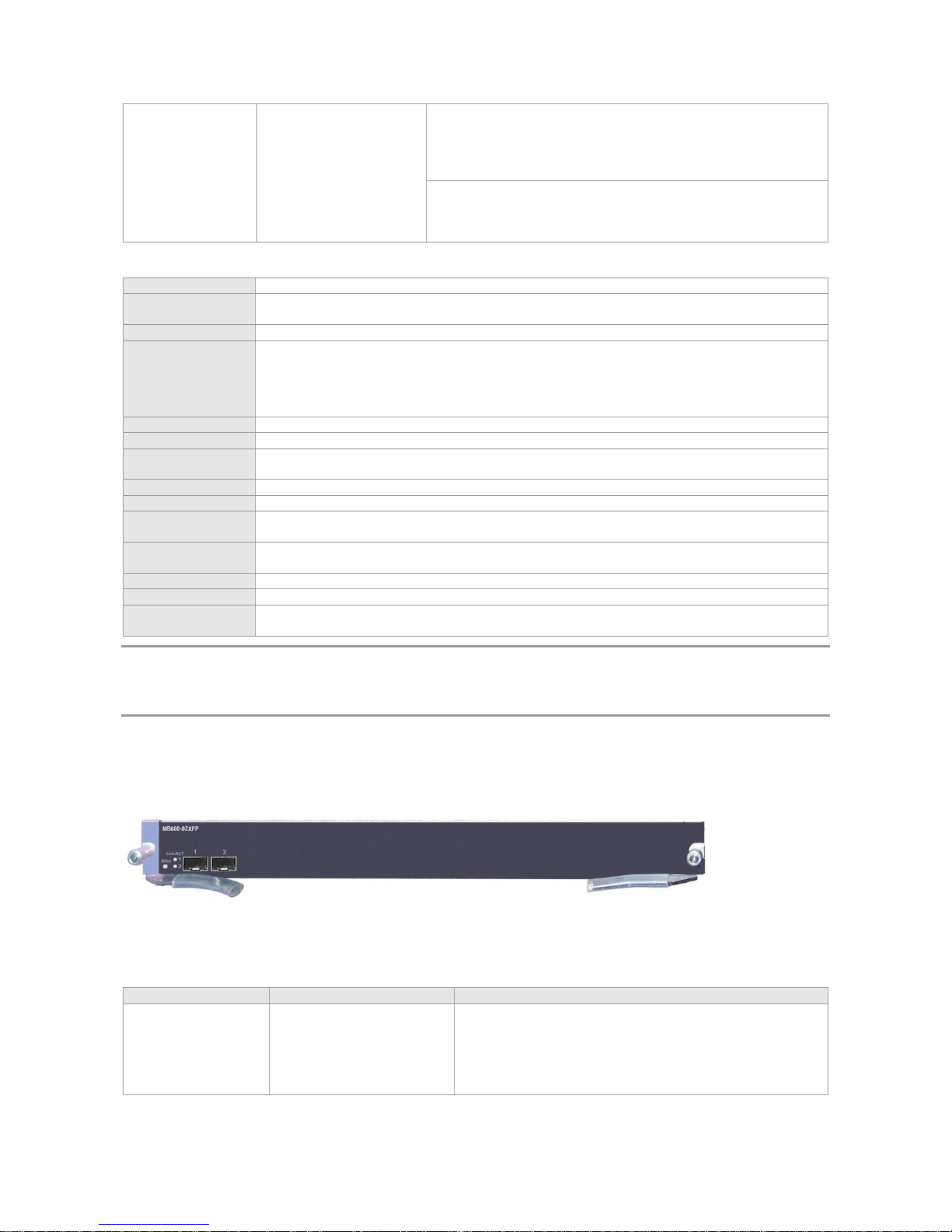
M8600-02XFP
It provides two 10G XFP ports. The XFP optical modules support hot swapping.
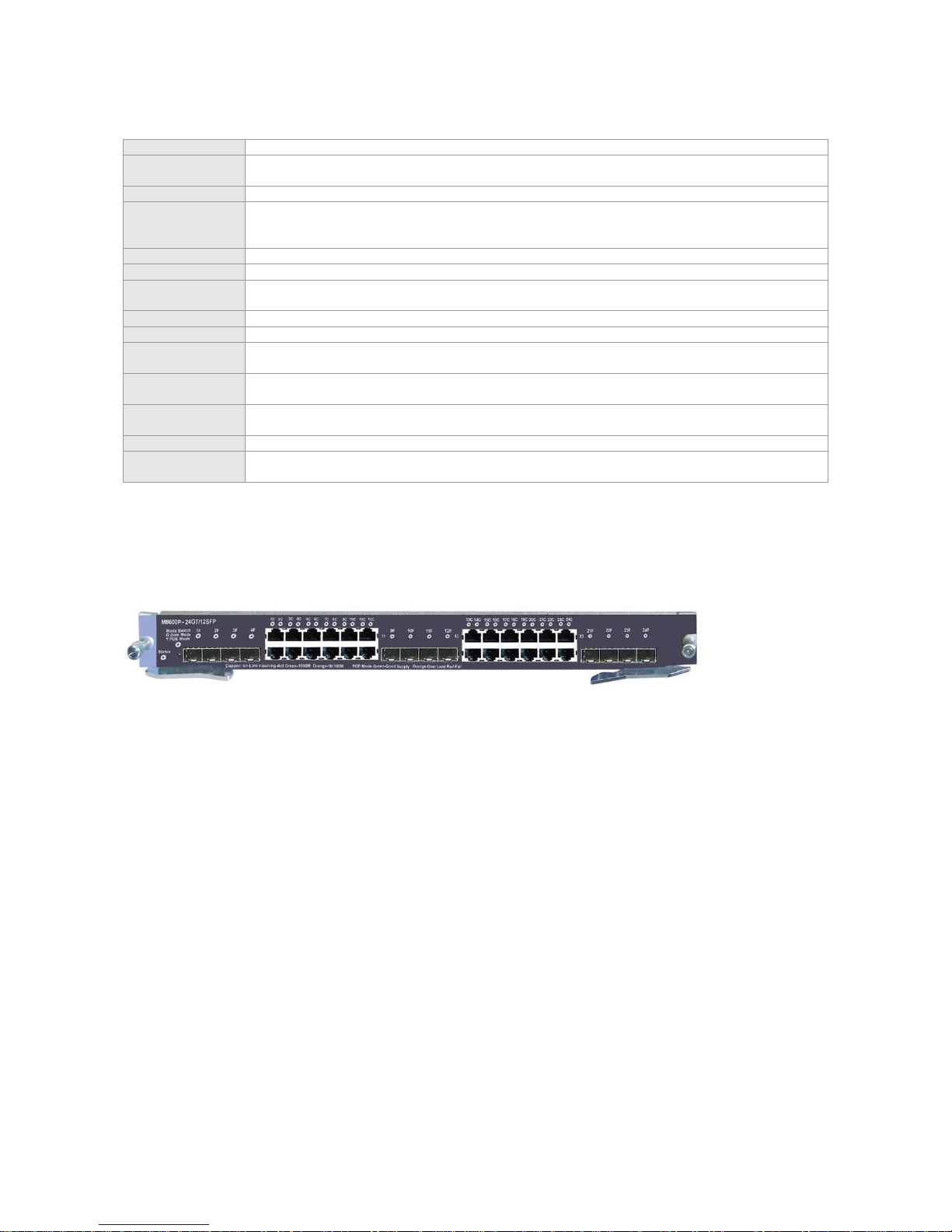
M8600P-24GT/12SFP
It provides twelve 10/100/1000BASE-T RJ45 ports and twelve fiber/copper combo
ports. The SFP ports support the rate of 1000M, and the RJ-45 ports support
auto-negotiation at 10/100/1000M and PoE function. The SFP optical modules
support hot swapping.
Page 20

M8600-48GT/4SFP
It provides forty-four 10/100/1000BASE-T RJ45 ports and four fiber/copper combo
ports. The SFP ports support the rate of 1000M, and the RJ-45 ports support
auto-negotiation at 10/100/1000M. The SFP optical modules support hot swapping.
M8600P-48GT/4SFP
It provides forty-four 10/100/1000BASE-T RJ45 ports and four fiber/copper combo
ports. The SFP ports support the rate at 1000M, and the RJ-45 ports support
auto-negotiation at 10/100/1000M and PoE function. The SFP optical modules
support hot swapping.
M8600-04XFP
It provides four 10G XFP ports. The XFP optical modules support hot swapping.
M8600-24SFP
It provides 24 SFP ports that support the rate of 100/1000M and hot swapping.
M8600-NMM
It is an agent card that supports network flow control. The line card does not provide
any external port, and the NMM function of the S8600 switches can be expanded
M8600-MPLS
It is an agent card that supports MPLS. The line card does not provide any external
port, and the MPLS function of the S8600 switches can be expanded
M8600-08XFP
It provides eight 10G XFP ports. The XFP optical modules support hot swapping.
M8600-02XFP24SFP/12GT-E
It provides two 10G XFP ports, twelve SFP ports and 1twelve fiber/copper combo
ports. The SFP ports support the rate of 1000M, and the RJ-45 ports support M
auto-negotiation at 10/100/1000. The XFP and SFP optical modules support hot
swapping.
M8600-VSU-02XFP
It supports VSU and provides two 10G XFP ports. The XFP optical modules support
hot swapping.
M8600-FW
It is a service card that supports the firewall function. The line card provides 1 serial
port and MGMT port, and the firewall function of the S8600 switches can be
expanded.
RG-WALL 1600-B-E
It is a service card that supports the firewall function. The line card provides 1 serial
port and MGMT port, and the firewall function of the S8600 switches can be
expanded.
RG-WALL 1600-B-U
It is a service card that supports the firewall function. The line card provides 1 serial
port and MGMT port, and the firewall function of the S8600 switches can be
expanded.
RG-WALL 1600 FW Module
It is a service card that supports the firewall function. The line card provides 1 serial
port and MGMT port, and the firewall function of the S8600 switches can be
expanded.
M8600-WS
It is a service card that supports the wireless control function and provides 1 serial
port and MGMT port. The wireless control function of the S8600 switches can be
expanded.
M8600-02XFP24SFP/12GT-EC
It provides two 10G XFP ports, 12 SFP ports and 12 fiber/copper combo ports. The
SFP ports support the rate of 100/1000M, and the RJ-45 ports support
auto-negotiation at 10/100/1000M. The XFP and SFP optical modules support hot
swapping.
M8600-24SFP/12GT-EC
It provides 12 SFP ports and 12 fiber/copper combo ports. The SFP ports support
the rate of 100/1000M, and the RJ-45 ports support auto-negotiation at
10/100/1000M. The SFP optical modules support hot swapping.
M8600-48GT/4SFP-EC
It provides forty-four 10/100/1000BASE-T RJ45 ports and four fiber/copper combo
ports. The SFP ports support the rate of 100/1000M, and the RJ-45 ports support
auto-negotiation at 10/100/1000M. The SFP optical modules support hot swapping.
M8600P-48GT/4SFP-EC
It provides forty-four 10/100/1000BASE-T RJ45 ports and four fiber/copper combo
ports. The SFP ports support the rate of 100/1000M, and the RJ-45 ports support
auto-negotiation at 10/100/1000M and PoE function. The SFP optical modules
support hot swapping.
M8600-24GT/12SFP-EC
It provides twelve 10/100/1000BASE-T RJ45 ports and twelve fiber/copper combo
ports. The SFP ports support the rate of 100/1000M, and the RJ-45 ports support
auto-negotiation at 10/100/1000M. The SFP optical modules support hot swapping.
M8600-04XFP-EC
It provides four 10G XFP ports. The XFP optical modules support hot swapping.
M8600-04QXS-DA
It provides four QSFP+ ports. The QSFP+ modules support hot swapping.
M8600-16XS-DA
It provides 16 SFP+ ports. The SFP+ ports support 10G SFP+ modules and Gigabit
SFP modules. The SFP and SFP+ modules support hot swapping.
M8614-FAN
As the fan tray of the system, it provides ten 120 x 120 x 38 fans to guarantee heat
dissipation of the system.
M8610/M8606-FAN
As the fan tray of the system, it provides six 120 x 120 x 38 fans to guarantee heat
dissipation of the system.
M8606-FAN B
As the fan tray of the system, it provides four 120 x 120 x 38 fans to guarantee heat
dissipation of the system.
RG-PA1200/PA1200E/
PA1200I/PA2000I/PA2000
As the AC power module of the system, it provides the input interface for 220V AC
power supply.
RG-PD1200/PD2000
As the DC power module of the system, it provides the input interface for -48V DC
power supply.
Page 21

RG-PA800IF
It is the AC power module of the system. Instead of providing an input interface, it is
directly powered by the 220V AC through the interface on the back of the S8606 B
chassis.
M8610/M8606-CM
M8610-CM is the primary management module of the RG-S8610; M8606-CM is the primary management module of
RG-S8606.M8610/M8606-CM performs such functions as system switching, system status control, route management,
user access control and management, and network maintenance. Inserted in slots M1 and M2 in the middle of the chassis,
the management module supports active/standby redundancy, hot backup and hot swapping.
In the system, there must be at least one M8610/M8606-CM for the system to work normally. However, you are
recommended to configure this module for both slots for higher reliability.
Module Appearance
Figure 1-9 Appearance of the M8610-CM
Figure 1-10 Appearance of the M8606-CM
External Interface
The M8610/M8606-CM module provides three external interfaces:
USB (Universal Serial Bus) interface: By connecting the USB interface, USB storage devices can keep logs, host
version, alarms and other diagnosis information, facilitating online upgrade of switch software and log saving.
To secure data and prevent damage to the device, it is recommended to use qualified USB disk. The USB interface
of the RG-S8600 is compatible with most USB controllers. Some models of USB disk may not be identified. You are
recommended to use Patriot and Start-net Digital USB disks.
Console port: As the serial communications port, it uses the RS-232 interface level and standard RJ-45 connector.
This port is used to connect the serial port of terminal computers running on the background for such tasks as
system debugging, configuration, maintenance, management, and host software loading.
10/100M MGMT port: As the 10/100BASE-T Ethernet port, it uses the RJ-45 connector. This port can be used to
connect the Ethernet port of the background computer for loading programs. When it is connected to the Ethernet
port of the background computer, the standard network cable can be used.
LED
Sign
Description
Detailed information
Status
System LED
OFF: The module is not powered on.
Red: The module is faulty.
Blinking green: The module is initializing. If it keeps blinking, the
module may be faulty.
Solid green: The module has finished initialization and can perform
switching well.
Primary
Primary/standby
management module
LED
OFF: The module is a standby management module.
Green: The module is a primary management module.
Alarm
Fault alarm
OFF: No fault.
Red: System fault.
10/100M MGMT
Port LED
Orange LED (full
duplex)
OFF: The module is working in the half duplex mode.
Orange: The module is working in the full duplex mode.
Green (Link/ACT)
OFF: The port link is not up.
Green: The port link is up.
Blinking green: The port is sending and receiving data.
Page 22

Specifications
Model
M8610-CM
M8606-CM
Standard Compliance
IEEE 802.3-2005 Ethernet Standard
Management Mode
CLI, Telnet, Web-based
Port Type
One console port for management, one 10/100M MGMT port, one USB port
LED
Status, Primary, Alarm and MGMT port LEDs
Hot Swapping
Supported
Management
Redundancy
Supported
Power Consumption
<30W
EMC Standards
GB9254-2008
Safety Standards
GB4943-2011
Operating
Temperature
0 to 40°C
Storage Temperature
-40 to 70°C
Operating Humidity
10% to 90% RH (non-condensing)
Weight
Net weight: 2.8 kg
Dimensions
(L x W x H)
436 mm x 346 mm x 30 mm
433 mm x 346 mm x 30 mm
The CR2032 lithium battery is used in the M8610/M8606-CM. There is a risk of explosion if battery is replaced by an
incorrect type. Dispose of used batteries in a proper way.
M8610/M8606-CM II LITE
The M8610-CM II LITE is the primary management module of the RG-S8610; M8606-CM II LITE is the primary
management module of the RG-S8606.M8610/M8606-CM performs such functions as system switching, system status
control, route management, user access control and management, network maintenance and multi-service card support.
Inserted in slots M1 and M2 in the middle of the chassis, the management module supports active/standby redundancy,
hot backup and hot swapping.
In the system, there must be at least one M8610/M8606-CM II LITE for the system to work properly. However, you
are recommended to configure this module for both slots for higher reliability.
Module Appearance
Figure 1-11 Appearance of the M8610-CM II LITE
Figure 1-12 Appearance of the M8606-CM II LITE
External Interface
The M8610/M8606-CM II LITE module provides three external interfaces:
USB (Universal Serial Bus) interface: By connecting the USB interface, USB storage devices can keep logs, host
version, alarms and other diagnosis information, facilitating online upgrade of switch software and log saving.
To secure data and prevent damage to the device, it is recommended to use qualified USB disk. The USB interface
of the RG-S8600 is compatible with most USB controllers. Some models of USB disk may not be identified. You are
recommended to use Patriot and Start-net Digital USB disks.
Console port: As the serial communications port, it uses the RS-232 interface level and standard the RJ-45
connector. This port is used to connect the serial port of terminal computers running on the background for such
tasks as system debugging, configuration, maintenance, management, and host software loading.
Page 23

10/100M MGMT port: As the 10/100BASE-T Ethernet port, it uses the RJ-45 connector. This port can be used to
connect the Ethernet port of the background computer for loading programs. When it is connected to the Ethernet
port of the background computer, the standard network cable can be used.
LED
Sign
Description
Detailed information
Status
System LED
OFF: The module is not powered on.
Red: The module is faulty.
Blinking green: The module is initializing. If it keeps blinking, the
module may be faulty.
Solid green: The module has finished initialization and can perform
switching well.
Primary
Primary/standby
management module
LED
OFF: The module is a standby management module.
Green: The module is a primary management module.
Alarm
Fault alarm
OFF: No fault.
Red: System fault.
10/100M MGMT
Port LED
Orange LED (full
duplex)
OFF: The module is working in the half duplex mode.
Orange: The module is working in the full duplex mode.
Green (Link/ACT)
OFF: The port link is not up.
Green: The port link is up.
Blinking green: The port is sending and receiving data.
Specifications
Model
M8610-CM II LITE
M8606-CM II LITE
Standard Compliance
IEEE 802.3-2005 Ethernet Standard
Management Mode
CLI, Telnet, Web-based
Port Type
One console port for management, one 10/100M MGMT port, one USB port
LED
Status, Primary, Alarm and MGMT port LEDs
Hot Swapping
Supported
Management
Redundancy
Supported
Power Consumption
<30W
EMC Standards
GB9254-2008
Safety Standards
GB4943-2011
Operating
Temperature
0 to 40°C
Storage Temperature
-40 to 70°C
Operating Humidity
10% to 90% RH (non-condensing)
Weight
Net weight: 2.8 kg
Dimensions
(L x W x H)
436 mm x 346 mm x 30 mm
433 mm x 346 mm x 30 mm
CR2032 lithium battery is used in M8610/M8606-CM II LITE. There is a risk of explosion if battery is replaced by an
incorrect type. Dispose of used batteries in a proper way.
M8614/M8610/M8606-CM II
The M8614-CM II is the primary management module of the RG-S8614; the M8610-CM II is the primary management
module of the RG-S8610; and the M8606-CM II is the primary management module of the RG-S8606. The
M8614/M8610/M8606-CM II performs such functions as system switching, system status control, route management, user
access control and management, and network maintenance. Inserted in slots M1 and M2 in the middle of the chassis, the
management module supports active/standby redundancy, hot backup and hot swapping.
In the system, there must be at least one M8614/M8610/M8606-CM II for the system to work properly. However, you
are recommended to configure this module for both slots for higher reliability.
Module Appearance
Figure 1-13 Appearance of the M8614-CM II LITE
Figure 1-14 Appearance of the M8610-CM II
Page 24
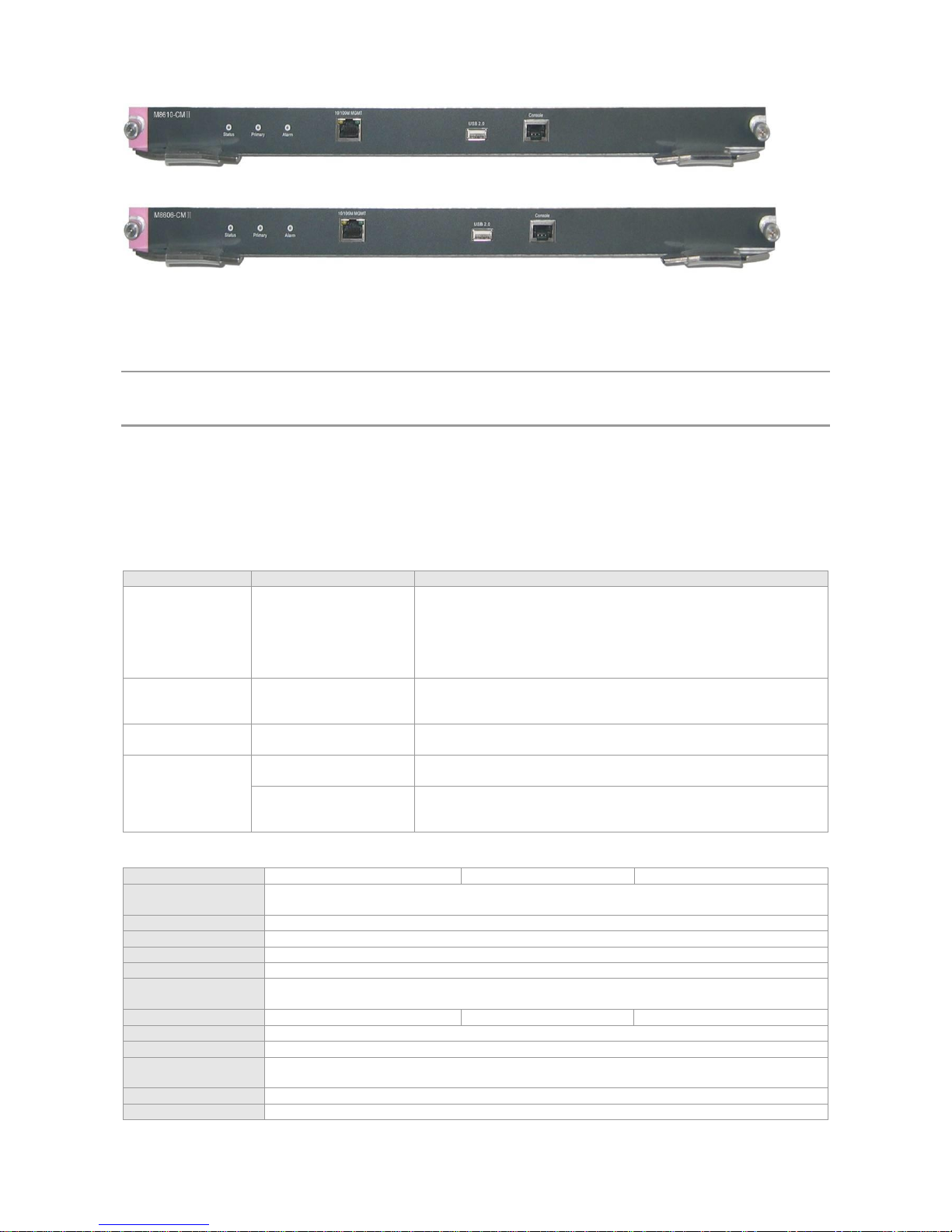
Figure 1-15 Appearance of M8610-CM II
External Interface
The M8614/M8610/M8606-CM II module provides three external interfaces:
USB (Universal Serial Bus) interface: By connecting the USB interface, USB storage devices can keep logs, host
version, alarms and other diagnosis information, facilitating online upgrade of switch software and log saving.
To secure data and prevent damage to the device, it is recommended to use qualified USB disk. The USB interface
of RG-S8600 is compatible with most USB controllers. Some models of USB disk may not be identified. You are
recommended to use Patriot and Start-net Digital USB disks.
Console port: As the serial communications port, it uses RS-232 interface level and standard RJ-45 connector. This
port is used to connect the serial port of terminal computers running on the background for such tasks as system
debugging, configuration, maintenance, management, and host software loading.
10/100M MGMT port: As the 10/100BASE-T Ethernet port, it uses RJ-45 connector. This port can be used to connect
the Ethernet port of the background computer for loading programs. When it is connected to the Ethernet port of the
background computer, the standard network cable can be used.
LED
Sign
Description
Detailed information
Status
System LED
OFF: The module is not powered on.
Red: The module is faulty.
Blinking green: The module is initializing. If it keeps blinking, the
module may be faulty.
Solid green: The module has finished initialization and can perform
switching well.
Primary
Primary/standby
management module
LED
OFF: The module is a standby management module.
Green: The module is a primary management module.
Alarm
Fault alarm
OFF: No fault.
Red: System fault.
10/100M MGMT
Port LED
Orange (speed)
OFF: The module is working in 10M mode
Orange: The module is working in 100M mode.
Green (Link/ACT)
OFF: The port link is not up.
Green: The port link is up.
Blinking green: The port is sending and receiving data.
Specifications
Model
M8614-CM II
M8610-CM II
M8606-CM II
Standard
Compliance
IEEE 802.3-2005 Ethernet Standard
Management Mode
CLI, Telnet, Web-based
Port Type
One console port for management, one 10/100M MGMT port, one USB port
LED
Status, Primary, Alarm and MGMT port LEDs
Hot Swapping
Supported
Management
Redundancy
Supported
Power Consumption
<80W
<50W
<50W
EMC Standards
GB9254-2008
Safety Standards
GB4943-2011
Operating
Temperature
0 to 40°C
Storage Temperature
-40 to 70°C
Operating Humidity
10% to 90% RH (non-condensing)
Page 25

Weight
Net weight: 3.5 kg
Net weight: 2.8 kg
Net weight: 2.8 kg
Dimensions
(L x W x H)
436 mm x 346 mm x 30 mm
436 mm x 346 mm x 30
mm
433 mm x 346 mm x 30 mm
The CR2032 lithium battery is used in the M8614/M8610/M8606-CM II. There is a risk of explosion if battery is
replaced by an incorrect type. Dispose of used batteries in a proper way.
M8610/M8606-CM III
The M8610-CM III is the primary management module of the RG-S8610; M8606-CM III is the primary management
module of the RG-S8606.M8610/M8606-CM III performs such functions as system switching, system status control, route
management, user access control and management, and network maintenance. Inserted in slots M1 and M2 in the middle
of the chassis, the management module supports active/standby redundancy, hot backup and hot swapping.
In the system, there must be at least one M8610/M8606-CM III for the system to work properly. However, you are
recommended to configure this module for both slots for higher reliability.
Module Appearance
Figure 1-16 Appearance of the M8610-CM III
Figure 1-17 Appearance of the M8606-CM III
External Interface
The M8610/M8606-CM III module provides three external interfaces:
USB (Universal Serial Bus) interface: By connecting the USB interface, USB storage devices can keep logs, host
version, alarms and other diagnosis information, facilitating online upgrade of switch software and log saving.
To secure data and prevent damage to the device, it is recommended to use qualified USB disk. The USB interface
of the RG-S8600 is compatible with most USB controllers. Some models of USB disk may not be identified. You are
recommended to use Patriot and Start-net Digital USB disks.
SD (Secure Digital Memory Card) interface: By connecting the SD interface, SD memory cards can keep logs, host
version, alarms and other diagnosis information, facilitating online upgrade of switch software and log saving.
To secure data and prevent damage to the device, it is recommended to use qualified SD memory cards. The SD
interface of the RG-S8600 is compatible with most SD memory cards. Some models of SD memory card may not be
identified.
Console port: As the serial communications port, it uses the RS-232 interface level and standard RJ-45 connector.
This port is used to connect the serial port of terminal computers running on the background for such tasks as
system debugging, configuration, maintenance, management, and host software loading.
10/100/1000M MGMT port: As the 10/100/1000BASE-T Ethernet port, it uses the RJ-45 connector. This port can be
used to connect the Ethernet port of the background computer for loading programs. When it is connected to the
Ethernet port of the background computer, the standard network cable can be used.
Reset button: As the reset button for the entire device, it resets the entire system.
There are long pressing and short pressing for the Reset button. If you press the button and hold it for less than five
seconds, it is short pressing; if you press the button and hold it for five seconds or longer, it is long pressing.
Indication of the Status LED for long pressing and short pressing: For short pressing of the button, the Status LED
flashes in green, and the board resets within five seconds at release. For long pressing of the button, the Status LED
flashes in green and then flashes in red; the board resets within five seconds at release.
LED
Page 26
Sign
Description
Detailed information
Status
System LED
OFF: The module is not powered on.
Red: The module is faulty.
Blinking green: The module is initializing. If it keeps blinking, the module
may be faulty.
Solid green: The module has finished initialization and can perform
switching well.
Primary
Primary/standby
management module LED
OFF: The module is a standby management module.
Green: The module is a primary management module.
Alarm
Fault alarm
OFF: No fault.
Red: System fault.
Link/ACT
MGMT port LED
OFF: The port link is not up.
Green: The port link is up at 1000 Mbps.
Yellow: The port link is up at 10 Mbps or 100 Mbps.
Blinking: The port is sending and receiving data.
SDS
SD port LED
OFF: SD card is not inserted in the port or fails to be loaded.
Red: SD card loading succeeds on the port.
Blinking green: SD card is being read and written
USBS
USB port LED
OFF: USB disk is not inserted in the port or fails to be loaded.
Red: USB disk loading succeeds on the port.
Blinking green: USB disk is being read and written.
Specifications
Model
M8610-CM III
M8606-CM III
Standard Compliance
IEEE 802.3-2005 Ethernet Standard
Management Mode
CLI, Telnet, Web-based
Port Type
One console port for management, one 10/100/1000M MGMT port,
One SD port, one USB port, one RESET button
LED
Status, Primary, Alarm, MGMT port LEDs, SD LED, USB LED
Hot Swapping
Supported
Management
Redundancy
Supported
Power Consumption
<91W
EMC Standards
GB9254-2008
Safety Standards
GB4943-2011
Operating Temperature
0 to 40°C
Storage Temperature
-40 to 70°C
Operating Humidity
10% to 90% RH (non-condensing)
Weight
Net weight: 2.8 kg
Dimensions
(L x W x H)
436 mm x 346 mm x 30 mm
433 mm x 346 mm x 30 mm
The CR2032 lithium battery is used in the M8610/M8606-CM III. There is a risk of explosion if battery is replaced by
an incorrect type. Dispose of used batteries in an proper way.
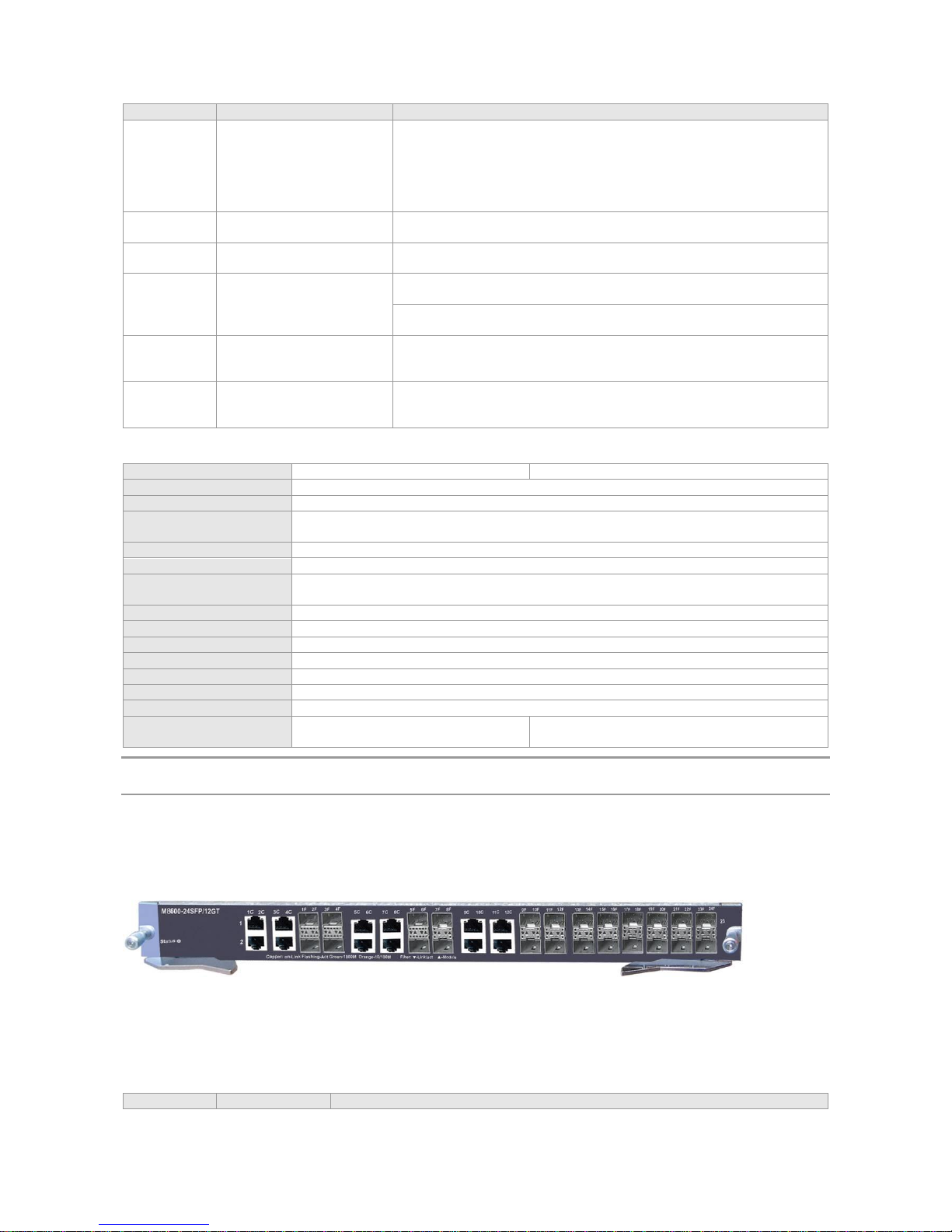
M8600-24SFP/12GT
Module Appearance
Figure 1-18 Appearance of the M8600-24SFP/12GT
External Interface
The M8600-24SFP/12GT provides 12 SFP ports and 12 fiber/copper combo ports. The SFP ports support the rate of
1000Mbps, the RJ45 ports support auto-negotiation at 10/100/1000 Mbps and the SFP optical modules support hot
swapping.
LED
Sign
Description
Detailed information
Page 27

Status
System LED
OFF: The module is not powered on.
Red: The module is faulty.
Blinking green: The module is initializing. If it keeps blinking, the module may be
faulty.
Solid green: The module has finished initialization and can perform switching well.
Module
Optical module
availability LED
OFF: The optical module is not available.
Green: The optical module is available.
Link/ACT
Port status LED
OFF: The port link is not up.
Green: The port link is up.
Blinking green: The port is sending and receiving data.
Specifications
Model
M8600-24SFP/12GT
Standard Compliance
IEEE 802.3-2005 Ethernet Standard
Port Type
Twelve SFP 1000 M ports and twelve 1000M fiber/copper combo ports
Transmission Medium
1000BASE-SX(850nm) Multi-mode optical fiber
1000BASE-LX(1310nm) Single-mode optical fiber
1000BASE-LH40(1310nm) Single-mode optical fiber
1000BASE-ZX(1550nm) Single-mode optical fiber
10/100/1000BASE-T Cat-5 UTP
LED
Status, Link/ACT, module LEDs
Hot Swapping
Supported
Power Consumption
<75W
EMC Standards
GB9254-2008
Safety Standards
GB4943-2011
Operating Temperature
0 to 40°C
Storage Temperature
-40 to 70°C
Operating Humidity
10% to 90% RH (non-condensing)
Weight
Net weight: 2.8 kg
Dimensions
(L x W x H)
436 mm x 346 mm x 45 mm
The M8600-24SFP/12GT module provides 12 10/100/1000BASE-T fiber/copper combo ports. In other words, each
10/100/1000BASE-T port corresponds to one combo SFP fiber port, and only one port can be used at a time, while
the other is unavailable. The automatic MDI/MDI-X identification of the 10/100/1000M copper ports takes effect only
when auto-negotiation is enabled.
M8600-24GT/12SFP
Module Appearance
Figure 1-19 Appearance of the M8600-24GT/12SFP
External Interface
The M8600-24GT/12SFP provides twelve 10/100/1000BASE-T RJ45 ports and twelve fiber/copper combo ports. The SFP
ports support the rate of 1000Mbps, the RJ45 ports support auto-negotiation at 10/100/1000 Mbps and the SFP optical
modules support hot swapping.
LED
Sign
Description
Detailed information
Status
System LED
OFF: The module is not powered on.
Red: The module is faulty.
Blinking green: The module is initializing. If it keeps blinking, the
module may be faulty.
Solid green: The module has finished initialization and can perform
switching well.
Page 28
Link/ACT
Port status LED
RJ45 port:
OFF: The port link is not up.
Green: The port link is up at 1000 Mbps.
Orange: The port link is up at 10/100 Mbps.
Blinking: The port is sending and receiving data.
SFP port:
OFF: The port link is not up.
Green: The port link is up.
Blinking green: The port is sending and receiving data.
Specifications
Model
M8600-24GT/12SFP
Standard
Compliance
IEEE 802.3-2005 Ethernet Standard
Port Type
Twelve 10/100/1000BASE-T RJ45 ports and twelve fiber/copper combo ports.
Transmission
Medium
1000BASE-SX(850nm) Multi-mode optical fiber
1000BASE-LX(1310nm) Single-mode optical fiber
1000BASE-LH40(1310nm) Single-mode optical fiber
1000BASE-ZX(1550nm) Single-mode optical fiber
10/100/1000BASE-T Cat-5 UTP
LED
Status, Link/ACT
Hot Swapping
Supported
Power
Consumption
<85W
EMC Standards
GB9254-2008
Safety Standards
GB4943-2011
Operating
Temperature
0 to 40°C
Storage
Temperature
-40 to 70°C
Operating Humidity
10% to 90% RH (non-condensing)
Weight
Net weight: 2.8 kg
Dimensions
(L x W x H)
436 mm x 346 mm x 45 mm
The M8600-24GT/12SFP module provides twelve 10/100/1000BASE-T SFP combo ports. In other words, each SFP
port corresponds to one 10/100/1000BASE-T port combo, and only one port can be used at a time, while the other is
unavailable. The automatic MDI/MDI-X identification of the 10/100/1000M copper ports takes effect only when
auto-negotiation is enabled.
M8600-02XFP
Module Appearance
Figure 1-20 Appearance of the M8600-02XFP
External Interface
M8600-02XFP provides two 10G XFP ports. The XFP optical modules support hot swapping.
LED
Sign
Description
Detailed information
Status
System LED
OFF: The module is not powered on.
Red: The module is faulty.
Blinking green: The module is initializing. If it keeps blinking,
the module may be faulty.
Solid green: The module has finished initialization and can
perform switching well.
Page 29

Link/ACT
Port status LED
OFF: The port link is not up.
Green: The port link is up.
Blinking green: The port is sending and receiving data.
Page 30
Specifications
Model
M8600-02XFP
Standard
Compliance
IEEE 802.3-2005 Ethernet Standard
Port Type
Two 10G XFP ports.
Transmission
Medium
10GBASE-SR(850nm) Multi-mode optical fiber
10GBASE-LR(1310nm) Single-mode optical fiber
10GBASE-ER(1550nm) Single-mode optical fiber
LED
Status, Link/ACT
Hot Swapping
Supported
Power
Consumption
<75W
EMC Standards
GB9254-2008
Safety Standards
GB4943-2011
Operating
Temperature
0 to 40°C
Storage
Temperature
-40 to 70°C
Operating
Humidity
10% to 90% RH (non-condensing)
Weight
Net weight: 2.8 kg
Dimensions
(L x W x H)
436 mm x 346 mm x 45 mm
M8600P-24GT/12SFP
Module Appearance
Figure 1-21 Appearance of the M8600-24GT/12SFP
External Interface
The M8600-24GT/12SFP provides twenty-four 10/100/1000BASE-T RJ45 ports and twelve fiber/copper combo ports. The
SFP ports support the rate of 1000Mbps, the RJ45 ports support auto-negotiation at 10/100/1000 Mbps and PoE function,
and the SFP optical modules support hot swapping.
Button
The Mode button has the following functions:
Press the “Mode” button, and the port LED indicates switchover between switching mode and PoE mode upon
releasing the button.
In the PoE mode, if the PSE is supplying power to PDs, pressing the “Mode” button and holding it for about three
seconds causes the PSE to stop supplying power to PDs upon releasing the button.
In the PoE mode, if the PSE is not supplying power to PDs, pressing the “Mode” button and holding it for about three
seconds makes the PSE begin supplying power to PDs upon releasing the button.
Page 31

LED
Sign
Description
Detailed information
Status
System LED
OFF: The module is not powered on.
Red: The module is faulty.
Blinking green: The module is initializing.
Solid green: The module has finished initialization and can
perform switching well.
Mode
Operating mode LED
Green: The module is working in the switching mode.
Yellow: The module is working in the PoE mode.
Link/ACT
Port status LED
The Mode LED is green (switching mode), RJ45 port:
OFF: The port link is not up.
Green: The port link is up at 1000 Mbps.
Orange: The port link is up at 10/100 Mbps.
Blinking: The port is sending and receiving data.
The Mode LED is green (switching mode), SFP port:
OFF: The port link is not up.
Green: The port link is up.
Blinking green: The port is sending and receiving data.
The Mode LED is yellow (PoE mode), RJ45 port:
OFF: The POE device is not working normally.
Green: The PoE device is working normally.
Orange: The PoE device is overloaded.
Red: The power supply on the port is faulty.
The Mode LED is yellow (PoE mode), SFP port:
OFF: No external PoE power supply on the port
Specifications
Model
M8600P-24GT/12SFP
Standard
Compliance
IEEE 802.3-2005 Ethernet Standard
IEEE 802.3af Power over Ethernet Standard
Port Type
Twelve 10/100/1000BASE-T 1000M RJ45 ports and twelve fiber/copper combo ports. Up to 24
PoE ports supported.
Transmission
Medium
1000BASE-SX(850nm) Multi-mode optical fiber
1000BASE-LX(1310nm) Single-mode optical fiber
1000BASE-LH40(1310nm) Single-mode optical fiber
1000BASE-ZX(1550nm) Single-mode optical fiber
10/100/1000BASE-T Cat-5 UTP
LED
Status, Link/ACT, mode LEDs
Hot Swapping
Supported
Power
Consumption
<85W+15.4xN (N indicates the number of PoE ports being used, N<=24)
EMC Standards
GB9254-2008
Safety Standards
GB4943-2011
Operating
Temperature
0 to 40°C
Storage
Temperature
-40 to 70°C
Operating Humidity
10% to 90% RH (non-condensing)
Weight
Net weight: 2.8 kg
Dimensions
(L x W x H)
436 mm x 346 mm x 45 mm
The M8600-24GT/12SFP module provides twelve 10/100/1000BASE-T SFP combo ports. In other words, each SFP
port corresponds to one combo 10/100/1000BASE-T port, and only one port can be used at a time, while the other is
unavailable. The automatic MDI/MDI-X identification of the 10/100/1000M copper ports takes effect only when
auto-negotiation is enabled.
The M8600P-24GT/12FP supports the PoE function, with a maximum of 15.4W of power output per port. If the host
is configured with the M8600P-24GT/12SFP line card, the power consumption should be calculated according to the
number of powered devices (PDs) attached and the power consumed by each PD.
The M8600P-24GT/12SFP is hot swappable. You need to perform the following operations before hot swapping:
1. Disconnect all cables connected to the PoE.
2. In the PoE mode, hold the Mode button for over three seconds until all LEDs on the line card go off.
Page 32

3. Configure the pull-out operation through software commands. (For relevant software configuration commands,
refer to the corresponding software description.)
Page 33

M8600-48GT/4SFP
Module Appearance
Figure 1-22 Appearance of the M8600-48GT/4SFP
External Interface
The M8600-48GT/4SFP provides forty-four 10/100/1000BASE-T RJ45 ports and four fiber/copper combo ports. The SFP
ports support the rate of 1000Mbps, RJ45 ports support auto-negotiation at 10/100/1000 Mbps and the SFP optical
modules support hot swapping.
LED
Sign
Description
Detailed information
Status
System LED
OFF: The module is not powered on.
Red: The module is faulty.
Blinking green: The module is initializing. If it keeps blinking, the module
may be faulty.
Solid green: The module has finished initialization and can perform
switching well.
Link/ACT
Port status LED
RJ45 port:
OFF: The port link is not up.
Green: The port link is up at 1000 Mbps.
Orange: The port link is up at 10/100 Mbps.
Blinking: The port is sending and receiving data.
SFP port:
OFF: The port link is not up.
Green: The port link is up.
Blinking green: The port is sending and receiving data.
Specifications
Model
M8600-48GT/4SFP
Standard
Compliance
IEEE 802.3-2005 Ethernet Standard
Port Type
Forty-four 10/100/1000BASE-T RJ45 ports and four fiber/copper combo ports.
Transmission
Medium
1000BASE-SX(850nm) Multi-mode optical fiber
1000BASE-LX(1310nm) Single-mode optical fiber
1000BASE-LH40(1310nm) Single-mode optical fiber
1000BASE-ZX(1550nm) Single-mode optical fiber
10/100/1000BASE-T Cat-5 UTP
LED
Status, Link/ACT
Hot Swapping
Supported
Power
Consumption
<100W
EMC Standards
GB9254-2008
Safety Standards
GB4943-2011
Operating
Temperature
0 to 40°C
Storage
Temperature
-40 to 70°C
Operating Humidity
10% to 90% RH (non-condensing)
Weight
Net weight: 3.5 kg
Dimensions
(L x W x H)
436 mm x 346 mm x 45 mm
The M8600-48GT/4SFP module provides four 10/100/1000BASE-T SFP combo ports. In other words, each SFP port
corresponds to one combo 10/100/1000BASE-T port, and only one port can be used at a time, while the other is
unavailable. The automatic MDI/MDI-X identification of the 10/100/1000M copper ports takes effect only when
auto-negotiation is enabled.
Page 34

M8600-04XFP
Module Appearance
Figure 1-23 Appearance of the M8600-04XFP
External Interface
The M8600-04XFP provides four 10G XFP ports. The XFP optical modules support hot swapping.
LED
Sign
Description
Detailed information
Status
System LED
OFF: The module is not powered on.
Red: The module is faulty.
Blinking green: The module is initializing. If it keeps blinking, the module
may be faulty.
Solid green: The module has finished initialization and can perform
switching well.
Link/ACT
Port status LED
OFF: The port link is not up.
Green: The port link is up.
Blinking green: The port is sending and receiving data.
Specifications
Model
M8600-04XFP
Standard
Compliance
IEEE 802.3-2005 Ethernet Standard
Port Type
Four 10G XFP ports.
Transmission
Medium
10GBASE-SR(850nm) Multi-mode optical fiber
10GBASE-LR(1310nm) Single-mode optical fiber
10GBASE-ER(1550nm) Single-mode optical fiber
LED
Status, Link/ACT
Hot Swapping
Supported
Power
Consumption
<100W
EMC Standards
GB9254-2008
Safety Standards
GB4943-2011
Operating
Temperature
0 to 40°C
Storage
Temperature
-40 to 70°C
Operating Humidity
10% to 90% RH (non-condensing)
Weight
Net weight: 3.5 kg
Dimensions
(L x W x H)
436 mm x 346 mm x 45 mm
M8600P-48GT/4SFP
Module Appearance
Figure 1-24 Appearance of the M8600-48GT/4SFP
External Interface
It provides forty-four 10/100/1000BASE-T RJ45 ports and four fiber/copper combo ports. The SFP ports support the rate
of 100/1000 Mbps, the RJ-45 ports support auto-negotiation at 10/100/1000 Mbps and PoE function, and the SFP optical
modules support hot swapping.
Button
Page 35

The Mode button has the following functions:
Press the “Mode” button, and the port LED indicates switchover between switching mode and PoE mode upon
releasing the button.
In the PoE mode, if the PSE is supplying power to PDs, pressing the “Mode” button and holding it for about three
seconds causes the PSE to stop supplying power to PDs upon releasing the button.
In the PoE mode, if the PSE is not supplying power to PDs, pressing the “Mode” button and holding it for about three
seconds makes the PSE begin supplying power to PDs upon releasing the button.
LED
Sign
Description
Detailed information
Status
System LED
OFF: The module is not powered on.
Red: The module is faulty.
Blinking green: The module is initializing. If it keeps blinking, the
module may be faulty.
Solid green: The module has finished initialization and can
perform switching well.
Mode
LED status indication
Green: indicates data exchange
Yellow: indicates PoE status
Link/ACT
Port status LED
When Mode LED is green, the module is in switching mode:
RJ45 port:
OFF: The port link is not up.
Green: The port link is up at 1000 Mbps.
Orange: The port link is up at 10/100 Mbps.
Blinking: The port is sending and receiving data.
SFP port:
OFF: The port link is not up.
Green: The port link is up.
Blinking green: The port is sending and receiving data.
When Mode LED is yellow, the module is in the switching mode:
RJ45 port:
OFF: The POE device is not working normally.
Green: The PoE device is working normally.
Orange: The PoE device is overloaded.
Red: The power supply on the port is faulty.
SFP port:
OFF: No external PoE power supply on the port
Specifications
Model
M8600P-48GT/4SFP
Standard
Compliance
IEEE 802.3-2005 Ethernet Standard
IEEE 802.3af Power over Ethernet Standard
Port Type
Forty-four 10/100/1000BASE-T 1000M RJ45 ports and four fiber/copper combo ports. Up to 48
PoE ports supported.
Transmission
Medium
1000BASE-SX(850nm) Multi-mode optical fiber
1000BASE-LX(1310nm) Single-mode optical fiber
1000BASE-LH40(1310nm) Single-mode optical fiber
1000BASE-ZX(1550nm) Single-mode optical fiber
10/100/1000BASE-T Cat-5 UTP
LED
Status, Link/ACT, mode LEDs
Hot Swapping
Supported
Power
Consumption
<100W+15.4xN (N indicates the number of PoE ports being used, N<=48)
EMC Standards
GB9254-2008
Safety Standards
GB4943-2011
Operating
Temperature
0 to 40°C
Storage
Temperature
-40 to 70°C
Operating Humidity
10% to 90% RH (non-condensing)
Weight
Net weight: 3.5 kg
Dimensions
(L x W x H)
436 mm x 346 mm x 45 mm
Page 36

The M8600-48GT/4SFP module provides four 10/100/1000BASE-T SFP combo ports. Each SFP port corresponds
to one combo 10/100/1000BASE-T port, and only one port can be used at a time, while the other is unavailable. The
automatic MDI/MDI-X identification of the 10/100/1000M copper ports takes effect only when auto-negotiation is
enabled.
The M8600P-48GT/4FP supports the PoE function, with a maximum of 15.4W of power output per port. If the host is
configured with the M8600P-48GT/4SFP line card, the power consumption should be calculated according to the
number of powered devices (PDs) attached and the power consumed by each PD.
The M8600P-48GT/4SFP supports hot swapping. You need to perform the following operations to achieve it:
1. Disconnect all cables connected to the PoE.
2. In the PoE mode, hold the Mode button for over three seconds until all LEDs on the line card go off.
3. Configure the pull-out operation through software commands. (For relevant software configuration commands,
refer to the corresponding software description.)
M8600-24SFP
Module Appearance
Figure 1-25 Appearance of the M8600-24SFP
External Interface
The M8600-24SFP provides 24 SFP ports that support the rate of 100/1000 Mbps and hot swapping.
LED
Sign
Description
Detailed information
Status
System LED
OFF: The module is not powered on.
Red: The module is faulty.
Blinking green: The module is initializing. If it keeps blinking, the module may be
faulty.
Solid green: The module has finished initialization and can perform switching well.
Link/ACT
Port status LED
OFF: The port link is not up.
Green: The 1000BASE-X port link is up.
Blinking green: The data is transmitted on the 1000BASE-X port.
Orange: The 100BASE-X port link is up.
Blinking orange: The data is transmitted on the 100BASE-X port.
Specifications
Model
M8600-24SFP
Standard Compliance
IEEE 802.3-2005 Ethernet Standard
Port Type
24 SFP 1000M/100M ports that support 1000BASE-X and100BASE-FX
Transmission Medium
1000BASE-SX(850nm) Multi-mode optical fiber
1000BASE-LX(1310nm) Single-mode optical fiber
1000BASE-LH40(1310nm) Single-mode optical fiber
1000BASE-ZX(1550nm) Single-mode optical fiber
100BASE-FX(1310nm) Multi-mode or single-mode optical fiber
100BASE-FX(1550nm) Single-mode optical fiber
LED
Status, Link/ACT LEDs
Hot Swapping
Supported
Power Consumption
<75W
EMC Standards
GB9254-2008
Safety Standards
GB4943-2011
Operating Temperature
0 to 40°C
Storage Temperature
-40 to 70°C
Operating Humidity
10% to 90% RH (non-condensing)
Weight
Net weight: 2.8 kg
Page 37

Dimensions
(L x W x H)
436 mm x 346 mm x 45 mm
M8600-MPLS
The M8600-MPLS is an agent card that supports MPLS. The MPLS function of S8600 switches can be expanded.
Module Appearance
Figure 1-26 Appearance of the M8600-MPLS
External Interface
The M8600-MPLS module provides no external ports.
LED
Sign
Description
Detailed information
Status
System LED
OFF: The module is not powered on.
Red: The module is faulty.
Blinking green: The module is initializing. If it keeps blinking, the
module may be faulty.
Solid green: The module has finished initialization and can
perform switching well.
Specifications
Model
M8600-MPLS
Standard Compliance
IEEE 802.3-2005 Ethernet Standard
LED
Status
Hot Swapping
Supported
Power Consumption
<100W
EMC Standards
GB9254-2008
Safety Standards
GB4943-2011
Operating
Temperature
0 to 40°C
Storage Temperature
-40 to 70°C
Operating Humidity
10% to 90% RH (non-condensing)
Weight
Net weight: 2.8 kg
Dimensions
(L x W x H)
436 mm x 346 mm x 45 mm
M8600-NMM
The M8600-NMM is an agent card that supports network flow control. The NMM function of S8600 switches can be
expanded.
Module Appearance
Figure 1-27 Appearance of the M8600-NMM
External Interface
The M8600-NMM module provides no external ports.
LED
Sign
Description
Detailed information
Page 38

Status
System LED
OFF: The module is not powered on.
Red: The module is faulty.
Blinking green: The module is initializing. If it keeps blinking, the
module may be faulty.
Solid green: The module has finished initialization and can
perform switching well.
Specifications
Model
M8600-NMM
Standard Compliance
IEEE 802.3-2005 Ethernet Standard
LED
Status
Hot Swapping
Supported
Power Consumption
<140W
EMC Standards
GB9254-2008
Safety Standards
GB4943-2011
Operating
Temperature
0 to 40°C
Storage Temperature
-40 to 70°C
Operating Humidity
10% to 90% RH (non-condensing)
Weight
Net weight: 3.0 kg
Dimensions
(L x W x H)
436 mm x 346 mm x 45 mm
M8600-08XFP
Module Appearance
Figure 1-28 Appearance of the M8600-08XFP
External Interface
The M8600-08XFP provides eight 10G XFP ports. The XFP optical modules support hot swapping.
LED
Sign
Description
Detailed information
Status
System LED
OFF: The module is not powered on.
Red: The module is faulty.
Blinking green: The module is initializing. If it keeps blinking, the
module may be faulty.
Solid green: The module has finished initialization and can perform
switching well.
Link/ACT
Port status LED
OFF: The port link is not up.
Green: The port link is up.
Blinking green: The port is sending and receiving data.
Specifications
Model
M8600-08XFP
Standard Compliance
IEEE 802.3-2005 Ethernet Standard
Port Type
Eight 10G XFP ports.
Transmission Medium
10GBASE-SR(850nm) Multi-mode optical fiber
10GBASE-LR(1310nm) Single-mode optical fiber
10GBASE-ER(1550nm) Single-mode optical fiber
LED
Status, Link/ACT
Hot Swapping
Supported
Power Consumption
<250W
EMC Standards
GB9254-2008
Safety Standards
GB4943-2011
Operating
Temperature
0 to 40°C
Storage Temperature
-40 to 70°C
Operating Humidity
10% to 90% RH (non-condensing)
Page 39

Weight
Net weight: 3.5 kg
Dimensions
(L x W x H)
436 mm x 346 mm x 45 mm
M8600-02XFP24SFP/12GT-E
Module Appearance
Figure 1-29 Appearance of the M8600-02XFP24SFP/12GT-E
External Interface
The M8600-02XFP24SFP/12GT-E provides two 10G XFP ports, twelve SFP ports and twelve fiber/copper combo ports.
The SFP ports support the rate of 1000Mbps, the RJ45 ports support auto-negotiation at 10/100/1000 Mbps and the XFP
and SFP optical modules support hot swapping.
LED
Sign
Description
Detailed information
Status
System LED
OFF: The module is not powered on.
Red: The module is faulty.
Blinking green: The module is initializing. If it keeps blinking, the
module may be faulty.
Solid green: The module has finished initialization and can perform
switching well.
Module
Optical module
availability LED
OFF: The optical module is not available.
Green: The optical module is available.
Link/ACT
Port status LED
OFF: The port link is not up.
Green: The port link is up.
Blinking green: The port is sending and receiving data.
Specifications
Model
M8600-02XFP24SFP/12GT-E
Standard
Compliance
IEEE 802.3-2005 Ethernet Standard
Port Type
Two 10G XFP ports, twelve SFP 1000M ports and twelve fiber/copper combo ports
Transmission
Medium
1000BASE-SX(850nm) Multi-mode optical fiber
1000BASE-LX(1310nm) Single-mode optical fiber
1000BASE-LH40(1310nm) Single-mode optical fiber
1000BASE-ZX(1550nm) Single-mode optical fiber
10/100/1000BASE-T Cat-5 UTP
LED
Status, Link/ACT, module LEDs
Hot Swapping
Supported
Power
Consumption
<75W
EMC Standards
GB9254-2008
Safety Standards
GB4943-2011
Operating
Temperature
0 to 40°C
Storage
Temperature
-40 to 70°C
Operating
Humidity
10% to 90% RH (non-condensing)
Weight
Net weight: 2.8 kg
Dimensions
(L x W x H)
436 mm x 346 mm x 45 mm
The M8600-02XFP24SFP/12GT-E module provides twelve 10/100/1000BASE-T combo ports with RJ45 ports as the
SFP fiber ports. In other words, each 10/100/1000BASE-T port corresponds to one combo SFP fiber port, and only
one port can be used at a time, while the other is unavailable. The automatic MDI/MDI-X identification of the
10/100/1000M copper ports takes effect only when auto-negotiation is enabled.
Page 40

M8600-VSU-02XFP
The M8600-VSU-02XFP module supports the VSU function.
Module Appearance
Figure 1-30 Appearance of the M8600-VSU-02XFP
External Interface
The M8600-VSU-02XFP provides two 10G XFP ports. The XFP optical modules support hot swapping.
LED
Sign
Description
Detailed information
Status
System LED
OFF: The module is not powered on.
Red: The module is faulty.
Blinking green: The module is initializing. If it keeps blinking,
the module may be faulty.
Solid green: The module has finished initialization and can
perform switching well.
Link/ACT
Port status LED
OFF: The port link is not up.
Green: The port link is up.
Blinking green: The port is sending and receiving data.
Specifications
Model
M8600-VSU -02XFP
Standard
Compliance
IEEE 802.3-2005 Ethernet Standard
Port Type
Two 10G XFP ports.
Transmission
Medium
10GBASE-SR(850nm) Multi-mode optical fiber
10GBASE-LR(1310nm) Single-mode optical fiber
10GBASE-ER(1550nm) Single-mode optical fiber
LED
Status, Link/ACT
Hot Swapping
Supported
Power
Consumption
<75W
EMC Standards
GB9254-2008
Safety Standards
GB4943-2011
Operating
Temperature
0 to 40°C
Storage
Temperature
-40 to 70°C
Operating
Humidity
10% to 90% RH (non-condensing)
Weight
Net weight: 2.8 kg
Dimensions
(L x W x H)
436 mm x 346 mm x 45 mm
Page 41

M8600-FW
The M8600-FW is a service card that supports the firewall function. The firewall function of S8600 switches can be
expanded.
Module Appearance
Figure 1-31 Appearance of the M8600-FW
External Interface
The M8600-FW module provides two external interfaces:
Console port: As the serial communications port, it uses RS-232 interface level and standard RJ-45 connector. This
port is used to connect the serial port of terminal computers running on the background for such tasks as firewall
debugging, configuration, maintenance, management, and host software loading.
10/100M MGMT port: As the 10/100BASE-T Ethernet port, it uses RJ-45 connector. This port can be used to connect
the Ethernet port of the background computer for loading programs.
LED
Sign
Description
Detailed information
Status
System LED
OFF: The module is not powered on.
Red: The module is faulty.
Blinking green: The module is initializing. If it keeps blinking, the
module may be faulty.
Solid green: The module has finished initialization and can perform
switching well.
10/100M MGMT
Port LED
Link/ACT
OFF: The port link is not up.
Green: The port link is up at 100 Mbps.
Yellow: The port link is up at 10 Mbps.
Blinking: The port is sending and receiving data.
Specifications
Model
M8600-FW
Standard
Compliance
IEEE 802.3-2005 Ethernet Standard
Port Type
One console port for management, one 10/100M MGMT port, no switching port
Transmission
Medium
None
LED
Status, Link/ACT
Hot Swapping
Supported
Power
Consumption
<90W
EMC Standards
GB9254-2008
Safety Standards
GB4943-2011
Operating
Temperature
0 to 40°C
Storage
Temperature
-40 to 70°C
Operating
Humidity
10% to 90% RH (non-condensing)
Weight
Net weight: 4.5 kg
Dimensions
(L x W x H)
436 mm x 346 mm x 45 mm
Page 42

RG-WALL1600-B-E
The RG-WALL 1600-B-E is a service card that supports the firewall function and can expand the firewall function of S8600
switches.
Module Appearance
Figure 1-32 Appearance of the RG-WALL 1600-B-E
External Interface
The RG-WALL 1600-B-E module provides two external interfaces:
Console port: As the serial communications port, it uses RS-232 interface level and standard RJ-45 connector. This
port is used to connect the serial port of terminal computers running on the background for tasks such as firewall
debugging, configuration, maintenance, management, and host software loading.
10/100M MGMT port: As the 10/100BASE-T Ethernet port, it uses RJ-45 connector. This port can be used to connect
the Ethernet port of the background computer for loading programs.
LED
Sign
Description
Detailed information
Status
System LED
OFF: The module is not powered on.
Red: The module is faulty.
Blinking green: The module is initializing. If it keeps blinking, the
module may be faulty.
Solid green: The module has finished initialization and can perform
switching well.
10/100M MGMT
Port LED
Link/ACT
OFF: The port link is not up.
Green: The port link is up at 100 Mbps.
Yellow: The port link is up at 10 Mbps.
Blinking: The port is sending and receiving data.
Specifications
Model
RG-WALL 1600-B-E
Standard
Compliance
IEEE 802.3-2005 Ethernet Standard
Port Type
One console port for management, one 10/100M MGMT port, no switching port
Transmission
Medium
None
LED
Status, Link/ACT
Hot Swapping
Supported
Power
Consumption
<90W
EMC Standards
GB9254-2008
Safety Standards
GB4943-2011
Operating
Temperature
0 to 40°C
Storage
Temperature
-40 to 70°C
Operating
Humidity
10% to 90% RH (non-condensing)
Weight
Net weight: 3.2 kg
Dimensions
(L x W x H)
436 mm x 346 mm x 45 mm
RG-WALL 1600-B-U
The RG-WALL 1600-B-U is a service card that supports the firewall function and can expand the firewall function of S8600
switches.
Page 43

Module Appearance
Figure 1-33 Appearance of the RG-WALL 1600-B-U
External Interface
The RG-WALL 1600-B-U module provides two external interfaces:
Console port: As the serial communications port, it uses RS-232 interface level and standard RJ-45 connector. This
port is used to connect the serial port of terminal computers running on the background for tasks such as firewall
debugging, configuration, maintenance, management, and host software loading.
10/100M MGMT port: As the 10/100BASE-T Ethernet port, it uses RJ-45 connector. This port can be used to connect
the Ethernet port of the background computer for loading programs.
LED
Sign
Description
Detailed information
Status
System LED
OFF: The module is not powered on.
Red: The module is faulty.
Blinking green: The module is initializing. If it keeps blinking, the
module may be faulty.
Solid green: The module has finished initialization and can perform
switching well.
10/100M MGMT
Port LED
Link/ACT
OFF: The port link is not up.
Green: The port link is up at 100 Mbps.
Yellow: The port link is up at 10 Mbps.
Blinking: The port is transceiving data.
Specifications
Model
RG-WALL 1600-B-U
Standard
Compliance
IEEE 802.3-2005 Ethernet Standard
Port Type
One console port for management, one 10/100M MGMT port, no switching port
Transmission
Medium
N/A
LED
Status, Link/ACT
Hot Swapping
Supported
Power
Consumption
<90W
EMC Standards
GB9254-2008
Safety Standards
GB4943-2011
Operating
Temperature
0 to 40°C
Storage
Temperature
-40 to 70°C
Operating
Humidity
10% to 90% RH (non-condensing)
Weight
Net weight: 3.2 kg
Dimensions
(L x W x H)
436 mm x 346 mm x 45 mm
RG-WALL 1600 FW Module
The RG-WALL 1600 FW is a service card that supports the firewall function and can expand the firewall function of the
S8600 switches.
Module Appearance
Figure 1-34 Appearance of the RG-WALL 1600 FW Module
Page 44

External Interface
The RG-WALL 1600 FW module provides two external interfaces:
Console port: As the serial communications port, it uses RS-232 interface level and standard RJ-45 connector. This
port is used to connect the serial port of terminal computers running on the background for such tasks as firewall
debugging, configuration, maintenance, management, and host software loading.
10/100M MGMT port: As the 10/100BASE-T Ethernet port, it uses RJ-45 connector. This port can be used to connect
the Ethernet port of the background computer for loading programs.
LED
Sign
Description
Detailed information
Status
System LED
OFF: The module is not powered on.
Red: The module is faulty.
Blinking green: The module is initializing. If it keeps blinking, the
module may be faulty.
Solid green: The module has finished initialization and can perform
switching well.
10/100M MGMT
Port LED
Link/ACT
OFF: The port link is not up.
Green: The port link is up at 100 Mbps.
Yellow: The port link is up at 10 Mbps.
Blinking: The port is sending and receiving data.
Specifications
Model
RG-WALL 1600 FW
Standard
Compliance
IEEE 802.3-2005 Ethernet Standard
Port Type
One console port for management, one 10/100M MGMT port, no switching port
Transmission
Medium
None
LED
Status, Link/ACT
Hot Swapping
Supported
Power
Consumption
<90W
EMC Standards
GB9254-2008
Safety Standards
GB4943-2011
Operating
Temperature
0 to 40°C
Storage
Temperature
-40 to 70°C
Operating
Humidity
10% to 90% RH (non-condensing)
Weight
Net weight: 4.5 kg
Dimensions
(L x W x H)
436 mm x 346 mm x 45 mm
M8600-WS
The M8600-WS is a service card that supports the wireless control function and can expand the wireless control function
of the S8600 switch.
Module Appearance
Figure 1-35 Appearance of M8600-WS
Page 45

External Interface
The M8600-WS module provides two external interfaces:
Console port: As the serial communications port, it uses RS-232 interface level and standard RJ-45 connector. This
port is used to connect the serial port of terminal computers running on the background for such tasks as the
debugging, configuration, maintenance, management, and host software loading of the wireless control card.
10/100M MGMT port: As the 10/100BASE-T Ethernet port, it uses RJ-45 connector. This port can be used to connect
the Ethernet port of the background computer for loading programs.
LED
Sign
Description
Detailed information
Status
System LED
OFF: The module is not powered on.
Red: The module is faulty.
Blinking green: The module is initializing. If it keeps blinking, the
module may be faulty.
Solid green: The module has finished initialization and can perform
switching well.
10/100M MGMT
Port LED
Link/ACT
OFF: The port link is not up.
Green: The port link is up at 100 Mbps.
Yellow: The port link is up at 10 Mbps.
Blinking: The port is sending and receiving data.
Specifications
Model
M8600-WS
Standard
Compliance
IEEE 802.3-2005 Ethernet Standard
Port Type
One console port for management, one 10/100M MGMT port, no switching port
Transmission
Medium
None
LED
Status, Link/ACT
Hot Swapping
Supported
Power
Consumption
<90W
EMC Standards
GB9254-2008
Safety Standards
GB4943-2011
Operating
Temperature
0 to 40°C
Storage
Temperature
-40 to 70°C
Operating
Humidity
10% to 90% RH (non-condensing)
Weight
Net weight: 4.5 kg
Dimensions
(L x W x H)
436 mm x 346 mm x 45 mm
M8600-02XFP24SFP/12GT-EC
Module Appearance
Figure 1-36 Appearance of the M8600-02XFP24SFP/12GT-EC
External Interface
The M8600-02XFP24SFP/12GT-EC provides two 10G XFP ports, twelve SFP ports and twelve fiber/copper combo ports.
The SFP ports support the rate of 100/1000 Mbps, the RJ45 ports support auto-negotiation at 10/100/1000 Mbps and the
XFP and SFP optical modules support hot swapping.
LED
Sign
Description
Detailed information
Page 46

Status
System LED
OFF: The module is not powered on.
Red: The module is faulty.
Blinking green: The module is initializing. If it keeps blinking, the
module may be faulty.
Solid green: The module has finished initialization and can perform
switching well.
Link/ACT
Port status LED
RJ45 port:
OFF: The port link is not up.
Green: The port link is up at 1000 Mbps.
Yellow: The port link is up at 10/100 Mbps.
Blinking: The port is sending and receiving data.
SFP port:
OFF: The port link is not up.
Green: The port link is up at 1000 Mbps.
Yellow: The port link is up at 100 Mbps.
Blinking: The port is sending and receiving data.
XFP port:
OFF: The port link is not up.
Green: The port link is up.
Blinking green: The port is sending and receiving data.
Specifications
Model
M8600-02XFP24SFP/12GT-EC
Standard Compliance
IEEE 802.3-2005 Ethernet Standard
Port Type
Two 10G XFP ports, twelve SFP ports and twelve fiber/copper combo ports
Transmission Medium
10GBASE-SR(850nm) Multi-mode optical fiber
10GBASE-LR(1310nm) Single-mode optical fiber
10GBASE-ER(1550nm) Single-mode optical fiber
1000BASE-SX(850nm) Multi-mode optical fiber
1000BASE-LX(1310nm) Single-mode optical fiber
1000BASE-LH40(1310nm) Single-mode optical fiber
1000BASE-ZX(1550nm) Single-mode optical fiber
100BASE-FX(1310nm) Multi-mode or single-mode optical fiber
100BASE-FX(1550nm) Single-mode optical fiber
10/100/1000BASE-T Cat-5 UTP
LED
Status, Link/ACT LEDs
Hot Swapping
Supported
Power Consumption
<100W
EMC Standards
GB9254-2008
Safety Standards
GB4943-2011
Operating Temperature
0 to 40°C
Storage Temperature
-40 to 70°C
Operating Humidity
10% to 90% RH (non-condensing)
Weight
Net weight: 3.3 kg
Dimensions
(L x W x H)
436 mm x 346 mm x 45 mm
The first 12 ports of the M8600-02XFP24SFP/12GT-EC service module are fiber/copper combo ports. Each SFP port
corresponds to one combo 10/100/1000BASE-T port and only one port can be used at a time, while the other is
unavailable. The automatic MDI/MDI-X identification of the 10/100/1000M copper ports takes effect only when
auto-negotiation is enabled.
The M8600-02XFP24SFP/12GT-EC supports 1000BASE-X and 100BASE-FX. You need to configure the ports as
the desired operating modes according to the Configuration Manual of Ruijie Networks.
M8600-24SFP/12GT-EC
Module Appearance
Figure 1-37 Appearance of the M8600-24SFP/12GT-EC
Page 47

External Interface
The M8600-24SFP/12GT-EC provides 12 SFP ports and 12 fiber/copper combo ports. The SFP ports support the rate of
100/1000 Mbps, the RJ-45 ports support auto-negotiation at 10/100/1000 Mbps, and the SFP optical modules support hot
swapping.
LED
Sign
Description
Detailed information
Status
System LED
OFF: The module is not powered on.
Red: The module is faulty.
Blinking green: The module is initializing. If it keeps blinking, the
module may be faulty.
Solid green: The module has finished initialization and can perform
switching well.
Link/ACT
Port status LED
RJ45 port:
OFF: The port link is not up.
Green: The port link is up at 1000 Mbps.
Yellow: The port link is up at 10/100 Mbps.
Blinking: The port is sending and receiving data.
SFP port:
OFF: The port link is not up.
Green: The port link is up at 1000 Mbps.
Yellow: The port link is up at 100 Mbps.
Blinking: The port is sending and receiving data.
Specifications
Model
M8600-24SFP/12GT-EC
Standard Compliance
IEEE 802.3-2005 Ethernet Standard
Port Type
12 SFP ports and 12 fiber/copper combo ports
Transmission Medium
1000BASE-SX(850nm) Multi-mode optical fiber
1000BASE-LX(1310nm) Single-mode optical fiber
1000BASE-LH40(1310nm) Single-mode optical fiber
1000BASE-ZX(1550nm) Single-mode optical fiber
100BASE-FX(1310nm) Multi-mode or single-mode optical fiber
100BASE-FX(1550nm) Single-mode optical fiber
10/100/1000BASE-T Cat-5 UTP
LED
Status, Link/ACT LEDs
Hot Swapping
Supported
Power Consumption
<84W
EMC Standards
GB9254-2008
Safety Standards
GB4943-2011
Operating Temperature
0 to 40°C
Storage Temperature
-40 to 70°C
Operating Humidity
10% to 90% RH (non-condensing)
Weight
Net weight: 3.2 kg
Dimensions
(L x W x H)
436 mm x 346 mm x 45 mm
The first 12 ports of the M8600-24SFP/12GT-EC service module are fiber/copper combo ports. Each SFP port
corresponds to one combo 10/100/1000BASE-T port, and only one port can be used at a time, while the other is
unavailable. The automatic MDI/MDI-X identification of the 10/100/1000M copper ports takes effect only when
auto-negotiation is enabled.
The M8600-24SFP/12GT-EC supports 1000BASE-X and 100BASE-FX. You need to configure the ports as the
desired operating modes according to the Configuration Manual of Ruijie Networks.
M8600-48GT/4SFP-EC
Module Appearance
Page 48

Figure 1-38 Appearance of the M8600-48GT/4SFP-EC
External Interface
The M8600-48GT/4SFP-EC provides forty-four 10/100/1000BASE-T RJ45 ports and four fiber/copper combo ports. The
SFP ports support the rate of 100/1000 Mbps, the RJ45 ports support auto-negotiation at 10/100/1000 Mbps and the SFP
optical modules support hot swapping.
LED
Sign
Description
Detailed information
Status
System LED
OFF: The module is not powered on.
Red: The module is faulty.
Blinking green: The module is initializing. If it keeps blinking, the
module may be faulty.
Solid green: The module has finished initialization and can perform
switching well.
Link/ACT
Port status LED
RJ45 port:
OFF: The port link is not up.
Green: The port link is up at 1000 Mbps.
Yellow: The port link is up at 10/100 Mbps.
Blinking: The port is sending and receiving data.
SFP port:
OFF: The port link is not up.
Green: The port link is up at 1000 Mbps.
Yellow: The port link is up at 100 Mbps.
Blinking: The port is sending and receiving data.
Specifications
Model
M8600-48GT/4SFP-EC
Standard Compliance
IEEE 802.3-2005 Ethernet Standard
Port Type
Forty-four 10/100/1000BASE-T RJ45 ports and four fiber/copper combo ports.
Transmission Medium
1000BASE-SX(850nm) Multi-mode optical fiber
1000BASE-LX(1310nm) Single-mode optical fiber
1000BASE-LH40(1310nm) Single-mode optical fiber
1000BASE-ZX(1550nm) Single-mode optical fiber
100BASE-FX(1310nm) Multi-mode or single-mode optical fiber
100BASE-FX(1550nm) Single-mode optical fiber
10/100/1000BASE-T Cat-5 UTP
LED
Status, Link/ACT
Hot Swapping
Supported
Power Consumption
<121W
EMC Standards
GB9254-2008
Safety Standards
GB4943-2011
Operating
Temperature
0 to 40°C
Storage Temperature
-40 to 70°C
Operating Humidity
10% to 90% RH (non-condensing)
Weight
Net weight: 3.6 kg
Dimensions
(L x W x H)
436 mm x 346 mm x 45 mm
The last four ports of the M8600-48GT/4SFP-EC service module are fiber/copper combo ports. Each SFP port
corresponds to one combo 10/100/1000BASE-T port, and only one port can be used at a time, while the other is
unavailable. The automatic MDI/MDI-X identification of the 10/100/1000M copper ports takes effect only when
auto-negotiation is enabled.
The M8600-48GT/4SFP-EC supports 1000BASE-X and 100BASE-FX. You need to configure the ports as the
desired operating modes according to the Configuration Manual of Ruijie Networks.
Page 49

M8600P-48GT/4SFP-EC
Module Appearance
Figure 1-39 Appearance of the M8600P-48GT/4SFP-EC
External Interface
The M8600P-48GT/4SFP-EC provides forty-four 10/100/1000BASE-T RJ45 ports and four fiber/copper combo ports. The
SFP ports support the rate of 100/1000 Mbps, the RJ45 ports support auto-negotiation at 10/100/1000 Mbps and PoE
function, and the SFP optical modules support hot swapping.
Button
The "Mode” button has the following functions:
Press the “Mode” button, and the port LED indicates switchover between switching mode and PoE mode upon
releasing the button.
In the PoE mode, if the PSE is supplying power to PDs, pressing the “Mode” button and holding it for about three
seconds causes the PSE to stop supplying power to PDs upon releasing the button.
In the PoE mode, if the PSE is not supplying power to PDs, pressing the “Mode” button and holding it for about three
seconds makes the PSE begin supplying power to PDs upon releasing the button.
LED
Sign
Description
Detailed information
Status
System LED
OFF: The module is not powered on.
Red: The module is faulty.
Blinking green: The module is initializing. If it keeps blinking, the
module may be faulty.
Solid green: The module has finished initialization and can
perform switching well.
Mode
Operating mode LED
Green: The module is working in the switching mode.
Yellow: The module is working in the PoE mode.
Link/ACT
Port status LED
When the Mode LED is green, RJ45 port:
OFF: The port link is not up.
Green: The port link is up at 1000 Mbps.
Yellow: The port link is up at 10/100 Mbps.
Blinking: The port is sending and receiving data.
When the Mode LED is green, SFP port:
OFF: The port link is not up.
Green: The port link is up at 1000 Mbps.
Yellow: The port link is up at 100 Mbps.
Blinking: The port is sending and receiving data.
When the Mode LED is yellow, RJ45 port:
OFF: The PoE device is not working normally.
Green: The PoE device is working normally.
Orange: The PoE device is overloaded.
Red: The power supply on the port is faulty.
When the Mode LED is yellow, SFP port:
OFF: No external PoE power supply on the port
Specifications
Model
M8600P-48GT/4SFP-EC
Standard Compliance
IEEE 802.3-2005 Ethernet Standard
IEEE 802.3af Power over Ethernet Standard
Port Type
Forty-four 10/100/1000BASE-T RJ45 ports and four fiber/copper combo ports. Up to 48 PoE
ports supported.
Page 50

Transmission Medium
1000BASE-SX(850nm) Multi-mode optical fiber
1000BASE-LX(1310nm) Single-mode optical fiber
1000BASE-LH40(1310nm) Single-mode optical fiber
1000BASE-ZX(1550nm) Single-mode optical fiber
100BASE-FX(1310nm) Multi-mode or single-mode optical fiber
100BASE-FX(1550nm) Single-mode optical fiber
10/100/1000BASE-T Cat-5 UTP
LED
Status, Link/ACT
Hot Swapping
Supported
Power Consumption
<121W+15.4xN (N indicates the number of PoE ports being used, N<=48)
EMC Standards
GB9254-2008
Safety Standards
GB4943-2011
Operating
Temperature
0 to 40°C
Storage Temperature
-40 to 70°C
Operating Humidity
10% to 90% RH (non-condensing)
Weight
Net weight: 3.8 kg
Dimensions
(L x W x H)
436 mm x 346 mm x 45 mm
The last four ports of the M8600P-48GT/4SFP-EC service module are fiber/copper combo ports. Each SFP port
corresponds to one combo 10/100/1000BASE-T port, and only one port can be used at a time, while the other is
unavailable. The automatic MDI/MDI-X identification of the 10/100/1000M copper ports takes effect only when
auto-negotiation is enabled.
The M8600P-48GT/4SFP-EC supports 1000BASE-X and 100BASE-FX. You need to configure the ports as the
desired operating modes according to the Configuration Manual of Ruijie Networks.
The M8600P-48GT/4FP-EC supports the PoE function, with a maximum of 15.4W of power output per port. If the
host is configured with the M8600P-48GT/4SFP-EC line card, the power consumption should be calculated
according to the number of powered devices (PDs) attached and the power consumed by each PD.
The M8600P-48GT/4SFP is hot swappable. You need to perform the following operations before hot swapping:
1. Disconnect all cables connected to the PoE;
2. In the PoE mode, hold the Mode button for over three seconds until all the LEDs on the line card go off;
3. Configure the pull-out operation through software commands.(For relevant software configuration commands,
refer to the corresponding software description.)
M8600-24GT/12SFP-EC
Module Appearance
Figure 1-40 Appearance of the M8600-24GT/12SFP-EC
External Interface
The M8600-24GT/12SFP-EC provides twelve 10/100/1000BASE-T RJ45 ports and twelve fiber/copper combo ports. The
SFP ports support the rate of 100/1000 Mbps, the RJ45 ports support auto-negotiation at 10/100/1000 Mbps and the SFP
optical modules support hot swapping.
LED
Sign
Description
Detailed information
Status
System LED
OFF: The module is not powered on.
Red: The module is faulty.
Blinking green: The module is initializing. If it keeps blinking, the
module may be faulty.
Solid green: The module has finished initialization and can perform
switching well.
Page 51

Link/ACT
Port status LED
RJ45 port:
OFF: The port link is not up.
Green: The port link is up at 1000 Mbps.
Yellow: The port link is up at 10/100 Mbps.
Blinking: The port is sending and receiving data.
SFP port:
OFF: The port link is not up.
Green: The port link is up at 1000 Mbps.
Yellow: The port link is up at 100 Mbps.
Blinking: The port is sending and receiving data.
Specifications
Model
M8600-24GT/12SFP-EC
Standard Compliance
IEEE 802.3-2005 Ethernet Standard
Port Type
Twelve 10/100/1000BASE-T RJ45 ports and twelve fiber/copper combo ports.
Transmission Medium
1000BASE-SX(850nm) Multi-mode optical fiber
1000BASE-LX(1310nm) Single-mode optical fiber
1000BASE-LH40(1310nm) Single-mode optical fiber
1000BASE-ZX(1550nm) Single-mode optical fiber
100BASE-FX(1310nm) Multi-mode or single-mode optical fiber
100BASE-FX(1550nm) Single-mode optical fiber
10/100/1000BASE-T Cat-5 UTP
LED
Status, Link/ACT LEDs
Hot Swapping
Supported
Power Consumption
<77W
EMC Standards
GB9254-2008
Safety Standards
GB4943-2011
Operating Temperature
0 to 40°C
Storage Temperature
-40 to 70°C
Operating Humidity
10% to 90% RH (non-condensing)
Weight
Net weight: 3.2 kg
Dimensions
(L x W x H)
436 mm x 346 mm x 45 mm
The last 12 ports of the M8600-24GT/12SFP-EC service card are fiber/copper combo ports. Each SFP port
corresponds to one combo 10/100/1000BASE-T port, and only one port can be used at a time, while the other is
unavailable. The automatic MDI/MDI-X identification of the 10/100/1000M copper ports takes effect only when
auto-negotiation is enabled.
The M8600-24GT/12SFP-EC supports 1000BASE-X and 100BASE-FX. You need to configure the ports as the
desired operating modes according to the Configuration Manual of Ruijie Networks.
M8600-04XFP-EC
Module Appearance
Figure 1-41 Appearance of the M8600-04XFP-EC
External Interface
The M8600-04XFP-EC provides four 10G XFP ports. The XFP optical modules support hot swapping.
LED
The M8600-04XFP-EC module provides LEDs indicating various system status, as described in the following table:
Sign
Description
Detailed information
Page 52

Status
System LED
OFF: The module is not powered on.
Red: The module is faulty.
Blinking green: The module is initializing. If it keeps blinking, the
module may be faulty.
Solid green: The module has finished initialization and can perform
switching well.
Link/ACT
Port status LED
OFF: The port link is not up.
Green: The port link is up.
Blinking green: The port is sending and receiving data.
Specifications
Model
M8600-04XFP-EC
Standard Compliance
IEEE 802.3-2005 Ethernet Standard
Port Type
Four 10G XFP ports.
Transmission Medium
10GBASE-SR(850nm) Multi-mode optical fiber
10GBASE-LR(1310nm) Single-mode optical fiber
10GBASE-ER(1550nm) Single-mode optical fiber
LED
Status, Link/ACT LEDs
Hot Swapping
Supported
Power Consumption
<100W
EMC Standards
GB9254-2008
Safety Standards
GB4943-2011
Operating Temperature
0 to 40°C
Storage Temperature
-40 to 70°C
Operating Humidity
10% to 90% RH (non-condensing)
Weight
Net weight: 3.1 kg
Dimensions
(L x W x H)
436 mm x 346 mm x 45 mm
Page 53

M8600-04QXS-DA
Module Appearance
Figure 1-42 Appearance of the M8600-04QXS-DA
External Interface
The M8600-04QXS-DA provides four QSFP+ ports. The QSFP+ ports support 40G QSFP+ modules working in 40G mode.
Hot swapping of the M8600-04QXS-DA and QSFP+ modules is supported.
LED
LED
Identification
on the panel
Status
Meaning
System LED
Status
Off
The module is NOT receiving power.
Solid red
The module is faulty.
Blinking
green
Initialization is in progress. Continuous blinking
indicates errors.
Solid green
The module is operational
QSFP+ port LED
Link/ACT
Off
The port link is NOT connected.
Solid green
The port is connected.
Blinking
The port is transmitting and receiving data.
Specifications
Model
M8600-04QXS-DA
Port type
Four QSFP+ ports. The QSFP+ ports support 40G QSFP+ modules working in 40G mode.
Transmission Medium
40GBASE-SR4 (850nm) Multi-mode optical fiber
40GBASE-CR4 Copper cable
LED
Status, Link/ACT LEDs
Hot Swapping
Supported
Power Consumption
< 126W
EMC Standards
GB9254-2008
Safety Standards
GB4943-2011
Operating Temperature
0 to 40°C
Storage Temperature
-40 to 70°C
Operating Humidity
10% to 90% RH (non-condensing)
Weight
Net weight: 5.1 kg
Dimensions
( L x W x H)
436 mm x 346 mm x 45 mm
Page 54

M8600-16XS-DA
Module Appearance
Figure 1-43 Appearance of the M8600-16XS-DA
External Interface
The M8600-16XS-DA provides 16 SFP+ ports. The SFP+ ports support 10G SFP+ modules and Gigabit SFP modules.
Hot swapping of the M8600-16XS-DA, SFP and SFP+ modules is supported.
RG-M8600-16XS-DA supports 10G SFP+ and Gigabit SFP modules. 10G SFP+ modules cannot be used as Gigabit
SFP modules.
LED
LED
Identification
on the panel
Status
Meaning
System LED
Status
Off
The module is NOT receiving power.
Solid red
The module is faulty.
Blinking
green
Initialization is in progress. Continuous blinking
indicates errors.
Solid green
The module is operational
SFP+ port LED
Link/ACT
Off
The port link is NOT connected.
Solid green
The port is connected.
Blinking
The port is transmitting and receiving data.
Specifications
Model
M8600-16XS-DA
Port type
16 SFP+ ports.
Transmission Medium
10GBASE-SR(850nm) Multi-mode optical fiber
10GBASE-LR(1310nm) Single-mode optical fiber
10GBASE-ER(1550nm) Single-mode optical fiber
1000BASE-SX(850nm) Multi-mode optical fiber
1000BASE-LX(1310nm) Single-mode optical fiber
1000BASE-LH40(1310nm) Single-mode optical fiber
1000BASE-ZX(1550nm) Single-mode optical fiber
SFP+ copper cable (1m/3m/5m) Passive copper cable
LED
Status, Link/ACT LEDs
Hot Swapping
Supported
Power Consumption
< 132W
EMC Standards
GB9254-2008
Safety Standards
GB4943-2011
Operating Temperature
0 to 40°C
Storage Temperature
-40 to 70°C
Operating Humidity
10% to 90% RH (non-condensing)
Weight
Net weight: 5.3 kg
Dimensions
( L x W x H)
436 mm x 346 mm x 45 mm
M8614/M8610/M8606-FAN/M8606-FAN B
The M8614-FAN is the fan module of the RG-S8614; the M8610-FAN is the fan module of the RG-S8610; the M8606-FAN
is the fan module of the RG-S8606; and M8606-FAN B is the fan module of the RG-S8606 B. M8614/M8610/M8606-FAN
forms a sound heat dissipation system of the entire system to ensure its stable operation.
Page 55

LED
The M8610/ M8606-FAN B module provides LEDs indicating various system status, as described in the following table:
Sign
Description
Detailed information
Power
Power LED
OFF: The fan tray is not powered on.
Solid green: The fan tray is normally powered on.
Alarm
Alarm LED
OFF: The fan tray is working normally.
Red: The fan tray is faulty.
In the RG-S8614/S8610/S8606/S8606 B system, an alarm on the fan tray M8614/M8610/M8606-FAN/M8606-FAN B
indicates that the fan tray has failed. In this case, you need to replace the failed one with a normal one as quickly as
possible.
The M8614/M8610/M8606-FAN/M8606-FAN B fan tray is hot swappable.
Specifications
Fan model
M8614-FAN
M8610-FAN
M8606-FAN
M8606-FAN B
Ventilation
118CFM x 10
118CFM x 6
118CFM x 6
174CFM x 4
Power Consumption
120W
60W
60W
150W
Weight
5.825 kg
4.29 kg
5.46 kg
3 kg
Dimensions
(W x H x D)
286.4 mm x 690.2
mm x 75.7 mm
432 mm x 66 mm x
374 mm
432.4 mm x 405.4
mm x 46.8 mm
310 mm x 257 mm x
64.4 mm
The depth of the M8614/M8606 fan module excludes the depth of the handle and captive screw.
RG-PA1200/PA1200E/PA1200I/PA2000I/PA2000/PA800IF
The AC power module RG-PA1200/PA1200E/PA1200I/PA2000I/PA2000 provides 110/220V AC power input module for
the RG-S8614/S8610/S8606. The AC power module RG-PA800IF provides 110/220V AC power input interface for the
RG-S8606B.
LED
RG-PA1200/PA1200E/PA1200I/PA2000I/PA2000 Module
Sign
Status
Details
IN
Off
No power input.
Solid green
Power input is operational.
OUT
Off
No power output.
Solid green
Power output is operational.
FAIL
Off
The power supply is operational.
Solid red
The power supply fails.
RG-PA800IF Module
Sign
Description
Details
Run
Power running LED
Green on indicates the power supply works normally. When
the “Fault” LED is red, or the “Alarm” LED is yellow not due to
over current, this "Run” LED goes off.
Alarm
Power alarm LED
Yellow on indicates the recoverable fault such as AC
overvoltage/under voltage protection, over current protection,
over-temperature protection or ps-off module shutdown
occurs on the power supply.
Fault
Power fault LED
Red on indicates the recoverable fault such as fan fault,
external short circuit, output overvoltage or the recoverable
fault occurs. That is, when the “Alarm” LED is yellow, the
“Fault” LED must be red.
According to the description of LEDs of the RG-PA800IF module, when the AC power supply input is connected or
the power supply switch is off, AC under voltage occurs due to no AC input, thus the “Alarm” LED is yellow, and the
“Fault” LED is red. And as long as the “Alarm” LED is yellow, the “Fault” LED is red. However, when the “Fault” LED
is red, the “Alarm” LED is not necessarily yellow.
Specifications
Page 56

Module Type
RG-PA1200
RG-PA1200E
RG-PA1200I
Rated Voltage
Range
100-240VAC, 50/60Hz
100-240VAC, 50/60Hz
100-120VAC, 200-240VAC, 50/60Hz
Maximum
Voltage Range
90-264VAC, 47/-63Hz
90-264VAC, 47-63Hz
90-264VAC, 47-63Hz
Maximum
Output Power
1200W
1200W
90-176VAC power: 530W
176-264VAC power: 1400W
Power Cable
10A
16A
16A
Module Type
RG-PA2000I
RG-PA2000
RG-PA800IF
Rated Voltage
Range
100-120VAC, 200-240VAC, 50/60Hz
100-240VAC, 50/60Hz
100-240VAC, 50-60Hz
Maximum
Voltage Range
90-264VAC, 47-63Hz
90-264VAC, 47-63Hz
90-264VAC, 47-63Hz
Maximum
Output Power
90-176VAC power: 1080W
176-264VAC power: 2000W
90-176VAC power: 1200W
176-264VAC power:
2000W
90-176VAC power: 400W
176-264VAC power:
800W
Power Cable
16A
16A
10A
The RG-S8614/S8610/S8606/S8606 B system supports 1+1 redundancy for the power supply. For higher stability
and reliability of the entire system, you are recommended to configure 1+1 power module redundancy for the
RG-S8614/S8610/S8606/S8606 B.
In dual power mode, shut down the power switch if PA1200/PA1200E/PD1200/PD2000 and PA2000
V1.00/V1.01/V1.02 coexist. No matter if the power cord is removed or not, the system prompts “LinkAndNoPower”
when you are viewing the power status.
In dual power mode, shut down the power switch if RG-PA1200I, RG-PA2000I, RG-PA2000 V1.10 and later version
coexist. If the power cord is connected, the system prompts “LinkAndPower” when you are viewing the power status;
if the power cord is removed, the system prompts “LinkAndNoPower” when you are viewing the power status. It is
recommended remove the power cord when you are shutting down the power.
RG-PD1200/PD2000
The DC power module RG-PD1200/PD2000 provides 48 V DC power input interface for RG-S8614/S8610/S8606.
LED
Sign
Status
Details
IN
Off
No power input.
Solid green
Power input is operational.
OUT
Off
No power output.
Solid green
Power output is operational.
FAIL
Off
The power supply is operational.
Solid red
The power supply fails.
Specifications
Module type
RG-PD1200
RG-PD2000
Rated Voltage
Range
-36VDC to -72VDC
-36VDC to -72VDC
Maximum
Output Power
1200W
2000W
Power Cable
63A
80A
RG-S8614/S8610/S8606/S8606 B system supports 1+1 redundancy for the power supply. For higher stability and
reliability of the entire system, you are recommended to configure 1+1 power module redundancy for the
RG-S8614/S8610/S8606/S8606 B.
Page 57

Chapter 2 Preparation Before Installation
Safety Suggestions
To avoid bodily injury and equipment damage, please carefully read the safety suggestions before you install
RG-S8614/S8610/S8606/S8606 B.
The following safety suggestions do not cover all possible dangers.
Safety Precautions for Installing the Device
Keep the chassis clean, free from any dust.
Do not place the equipment in a walking area.
Do not wear loose clothes or any other things that may be caught by the chassis during installation and maintenance.
Turn off all power supplies and unplug all power cords before you move the chassis.
RG-S8614/S8610/S8606/S8606 B is large and heavy. When you handle them, please pay attention to the following
requirement:
Avoid moving the equipment frequently.
At least two people are needed to move the equipment. Do not attempt to move the equipment by one person only.
Keep balance when moving the equipment, and avoid injuring your leg and feet or spraining your waist.
Turn off all power supplies and unplug all power cables before you move the equipment.
First move all the line cards, fan tray, and power module from the chassis before you move the
RG-S8614/S8610/S8606/S8606 B by using the handles on both sides, to avoid any damage.
Figure 2-1 Moving the RG-S8614 Switch
Figure 2-2 Moving the RG-S8610 Switch
Page 58

Figure 2-3 Moving the RG-S8606 Switch
Figure 2-4 Moving the RG-S8606 B Switch
Page 59

Do not move the equipment by grasping the panel, power supply handle, ventilation holes of the chassis, as they are
not designed to bear the weight of the entire equipment. This may cause damage or even injure you.
Remove all Management modules, service modules and power modules before you move the device, to reduce the
chassis weight.
The device must be installed and used in the restricted access location.
Electrical Safety Precautions
Please observe local regulations and specifications when performing electrical operations. Relevant operators must
be qualified.
Please carefully check for any potential danger in the working area, for example, ungrounded power supply,
unreliable grounding of the power supply and damp/wet ground or floor.
Find out the location of the emergency power supply switch in the room before installation. First cut off the power
supply in cases of an accident.
Do not operate while the power is on.
Do not maintain the equipment alone when it is powered on, unless absolutely necessary.
Be sure to make a careful check before you shut down the power supply.
Do not place the equipment in a damp/wet location. Do not let any liquid enter the chassis
Connect the negative and positive lines correctly according to the instructions when DC power supply is used.
Any nonstandard and inaccurate electrical operation can cause an accident such as fire or electrical shock, thus
causing severe even fatal damages to human bodies and equipment.
Direct contact or indirect contact through a wet object with high-voltage and mains supply can bring a fatal danger.
Static Discharge Damage Prevention
Although much has been done in RG-S8614/S8610/S8606/S8606 B to prevent static electricity, great damage may be
caused to the circuitry and equipment when the static electricity exceeds a certain limit. Electrostatic induction may come
from the following sources: External electric field produced by the high-voltage supply cable and lightning, and internal
systems such as the indoor floor and the entire structure.
To prevent damage from static electricity, you must pay attention to the following:
Page 60

Properly ground the equipment.
Take dust prevention measures in the room.
Maintain an appropriate humidity.
Always wear an anti-static wrist strap when you touch any circuit board.
Try to hold a circuit board by its edges. Do not touch any components or the PCB.
Use an anti-static shielding bag to store the board properly.
Do not let any clothes touch a circuit board. An antistatic wrist strap can only prevent human static electricity from
damaging the circuit board, but cannot prevent any static electricity on clothes.
Wearing an Anti-Static Wrist Trap
The S8600 series switches are equipped with an anti-static wrist trap. To protect electronic components against static
electricity, wear an anti-static wrist trap close to your skin and have it properly grounded while installing swappable
modules.
Use an anti-static wrist trap as follows:
1) Ensure that the switch is properly grounded. For details, see section 3.10 “Grounding.”
2) Put your hand in the anti-static wrist trap.
3) Tighten the buckle till the trap is closely attached to your skin.
4) Insert the grounding terminal of the trap into the trap jack in the switch chassis, as shown in Figure 2-5.
For safety, use a multimeter to measure the resistance between yourself and the ground, which should be within the
range of 1–10 Ω.
Make sure that the switch is properly grounded when the anti-static wrist trap is connected to the ground through the
chassis jack.
Figure 2-5 Wearing an anti-static wrist trap (for an RG-S8600 switch)
Page 61

Laser Safety
Among the modules supported by RG-S8614/S8610/S8606/S8606 B, there are a great number of optical modules that
are Class I laser products. Therefore, pay attention to the following during your use of this product:
When a fiber transceiver works, ensure that the port has been connected with an optic fiber so as to keep out dust
and avoid burning your eyes.
Cover the unused optical ports with dust caps.
Do not stare into any optical port.
Do not get close to or stare into any optical port under any circumstances, as this may cause permanent damage to
your eyes.
Installation Site Requirements
RG-S8614/S8610/S8606/S8606 B must be used in the room. To ensure normal operation and a prolonged use life of the
equipment, the installation site must meet the following requirements.
Rack Mounting Requirements
To mount the RG-S8614/S8610/S8606/S8606 B in a frame, verify that the frame meets the following conditions:
Install the switch in an open cabinet as much as possible. If you install the switch inside an enclosed cabinet, be sure
that the cabinet has a good ventilation and heat dissipation system.
Be sure that the cabinet is firm enough to bear the weight of the RG-S8614/S8610/S8606/S8606 B and its
installation accessories.
Be sure that the dimensions of the cabinet is appropriate for installation of the RG-S8614/S8610/S8606/S8606 B that
can reserve a certain space for the front, rear, left and right panels for heat dissipation.
The frame should be properly grounded.
Ventilation and Heat Dissipation Requirements
Sufficient space (10 cm at least) must be reserved at the air intakes and exhaust vents for ventilation.
After connecting various cables, you should bundle the cables or place them in the cable management bracket to
avoid blocking air inlets.
Page 62

Figure 2-6 Ventilation of RG-S8614
Page 63

Figure 2-7 Ventilation of RG-S8610
Figure 2-8 Ventilation of RG-S8606
Page 64

Figure 2-9 Ventilation of RG-S8606 B
Remove all foam packaging materials and protective plastics before you power on
RG-S8614/RG-S8610/RG-S8606/RG-S8606B.
Temperature and Humidity Requirements
To ensure the normal operation and a prolonged use life of the RG-S8614/S8610/S8606/S8606 B, you must maintain an
appropriate temperature and humidity in the equipment room. Too high or low temperature and humidity for a long period
of time may damage the equipment.
In an environment with high relative humidity, the insulating material may have bad insulation or even leak electricity,
and sometimes the materials may suffer from mechanical performance change and metallic parts may get rusted.
On the other hand, in an environment with low relative humidity, the insulating strip may dry and shrink, and static
electricity may occur easily and endanger the circuit on the equipment.
In an environment with high temperature, the device performance greatly degrades and all kinds of hardware faults
happen. And long-term exposure to high temperature expedites the aging process.
Temperature and humidity requirements of the RG-S8614/S8610/S8606
Temperature
Relative Humidity
Working condition
Non-working condition
Working condition
Non-working condition
0ºC–40ºC
–40ºC to +70ºC
10%–90%RH
(non-condensing)
10%–95%RH
(non-condensing)
Temperature and humidity requirements of the RG-S8606 B
Temperature
Relative Humidity
Working condition
Non-working condition
Working condition
Non-working condition
0ºC–50ºC
–40ºC to +70ºC
10%–90%RH
(non-condensing)
10%–95%RH
(non-condensing)
Note: The ambient temperature and humidity are measured at the point that is 1.5m above the floor and 0.4m before
the equipment when there is no protective plate in front or back of the equipment rack.
Page 65

Cleanness Requirements
Dust poses the top threat to the running of the equipment. The indoor dust falling on the equipment may be adhered by
the static electricity, causing bad contact of the metallic joint. Such electrostatic adherence may occur more easily when
the relative humidity is low, not only affecting the use life of the equipment, but also causing communication faults. The
following table shows the requirements for the dust content and granularity in the equipment room.
Substance
Concentration Limit (particles/m3)
Dust particles (diameter ≥0.5μm)
≤3.5×10⁶
Dust particles (diameter ≥5μm)
≤3×10⁴
The air filter of the RG-S8614/S8610/S8606 B must be cleaned regularly to ensure good ventilation and dust
prevention.
Apart from dust, the salt, acid and sulfide in the air in the equipment room must also meet strict requirements; as such
poisonous substances may accelerate the corrosion of the metal and the aging of some parts. The equipment room
should be protected from the intrusion of harmful gases (for example, sulfur dioxide, sulfured hydrogen, nitrogen dioxide,
and chlorine), whose requirements are listed in the following table.
Gas
Average (mg/m3)
Maximum (mg/m3)
SO2
0.3
1.0
H2S
0.1
0.5
NO2
0.5
1.0
Cl2
0.1
0.3
The Average refers to the average limit of harmful gas in one week. The Maximum value is the upper limit of the
harmful gas measured in one week for up to 30 minutes every day.
Dusting Cycle Suggestions:
1. Clean the air filters every three months.
2. Dust the air intakes and exhaust vents of all modules every three months.
3. Dust the modules every one or two years.
4. Dust the fan shelves yearly.
5. Dust the chassis, including the backboard, every one or two years.
If the device is in a poor dust prevention environment, please increase the dusting times.
Power Requirements
Model
Power Module
Input Voltage
RG-S8614/S8610/S8606
AC power module: RG-PA1200
90–264 VAC, 47–63 Hz
AC power module: RG-PA1200E
90–264 VAC, 47–63 Hz
AC power module: RG-PA1200I
90–264 VAC, 47–63 Hz
AC power module: RG-PA1200
90–264 VAC, 47–63 Hz
AC power module: RG-PA1200I
90–264 VAC, 47–63 Hz
DC power module: RG-PD1200
-36 VDC–72 VDC
DC power module: RG-PD1200
-36 VDC–-72 VDC
RG- S8606 B
AC power module: RG-PA800IF
90–264 VAC, 47–63 Hz
The RG-S8614/S8610/S8606/S8606 B provides 1+1 redundancy of power supply. You are recommended to use
multiple power supplies for the equipment to ensure its continuous and stable operation by avoiding the impact of
unexpected power failures on the equipment.
When the dual power supply is applied, the type of the power supply should be identical.
Page 66

System Grounding Requirements
A good grounding system is the basis for the stable and reliable operation of the RG-S8614/S8610/S8606/S8606 B. It is
the key to prevent lightning strike and resist interference. Please carefully check the grounding conditions on the
installation site according to the grounding requirements, and perform grounding properly as needed.
Safety Grounding
The equipment using AC power supply must be grounded by using the orange/green safety grounding cable. Otherwise,
when the insulating resistance decreases the power supply and the enclosure in the equipment, electric shock may occur.
The building installation shall provide a means for connection to protective earth, and the equipment is to be
connected to that means.
Lightning Grounding
The lightning protection system of the facility is a separate system that consists of the lightning rod, conductor and the
connector to the grounding system, which usually shares the power reference ground and orange/green safety cable
ground. The lightning discharge ground is for the facility only, irrelevant to the equipment. For the switch lighting protection,
refer to Appendix C.
EMC Grounding
The ground required for EMC design includes shielding ground, filter ground, noise and interference suppression, and
level reference. All the above constitute the comprehensive grounding requirements. The grounding resistance should be
less than 1 ohm.
The RG-S8614/S8610/S8606/S8606 B chassis is installed with one grounding pole for shell protection which is required to
connect the grounding pole of the cabinet, as shown in Figure 2-10.
Figure 2-10 Grounding of the RG-S8614/S8610/S8606/S8606 B
EMI Consideration
Various interference sources, from either outside or inside the equipment or application system, affect the system in the
conductive ways such as capacitive coupling, inductive coupling, and electromagnetic radiation. There are two types of
electromagnetic interferences: radiated interference and conducted interference, depending on the type of the
propagation path. When the energy, often RF energy, from a component arrives at a sensitive component via the space,
the energy is known as radiated interference. The interference source can be both a part of the interfered system and a
completely electrically isolated unit. Conducted interference results from the electromagnetic wire or signal cable
connection between the source and the sensitive component, along the cable the interference conducts from one unit to
another. Conducted interference often affects the power supply of the equipment, but can be controlled by a filter.
Radiated interference may affect any signal path in the equipment, and is difficult to shield.
To ensure that the equipment works properly, you must connect cables properly. Before you connect the cables, please
carefully read the following precautions.
Effective measures should be taken for the power system to prevent the interference from the electric grid.
Page 67

The working ground of the routers should be properly separated and kept as far as possible from the grounding
device of the power equipment or the anti-lightning grounding device.
Keep the equipment away from high-power radio transmitter, radar transmitting station, and high-frequency
large-current device.
Measures must be taken to isolate static electricity.
Precaution for Fiber Connection
Before connecting the fibers, you should ensure that the type of optical connector and the type of fibers match the type of
the optical interface used. Moreover, you should pay attention to the Tx and Rx directions of the fiber. The Tx end of this
equipment should be connected to the Rx end of the peer equipment, and the Rx end of this equipment to the Tx end of
the peer equipment.
Installation Tool Requirements
Common tools
Phillips screwdriver, flat screwdriver, related electric and optical cables
Bolts, diagonal pliers, straps
Special-purpose Tools
Anti-static tool
Meter
Multimeter
RG-S8614/S8610/S8606/S8606 B series is not shipped with a tool kit. You need to prepare a tool kit by yourself.
Unpacking Requirements
Goods Checklist
Chassis Packing
Box
All panels have been properly installed and commissioned.
Screws
Documentation
Packing list
Accessory Box
A correct AC or DC power module is delivered.
Cable management bracket (only for the RG-S8610)
Air filter (for the RG-S8614/S8610/S8606 B only)
Handles
Fan tray
Power cords (for AC power supply only)
Screws
Documentation
Packing list
Module Packing
Box
Modules, packing list and documentation.
A normal delivery should contain the above mentioned items, which may differ from the actual delivery, depending on
purchase contracts. Please check your goods carefully against the packing list or purchase contract. If you have any
questions or there are any errors, please contact your distributor.
Page 68

Chapter 3 Product Installation
Before you install the RG-S8614/S8610/S8606/S8606 B, make sure you have carefully read Chapter 2 and this part.
Be sure that the requirements set forth in part 2 have been met.
Installation Procedure
Page 69

Installation Verification
The RG-S8614/S8610/S8606/S8606 B is complicated equipment, so you must carefully plan the installation location,
networking mode, power supply, and wiring before installation.
Verify the following before installation:
The installation location meets the heat dissipation requirements..
The installation environment meets the temperature and humidity requirements
The qualified power supply is available at the installation location.
The related network cables have already been deployed at the installation location.
Rated DC or AC power supply is selected.
Selecting the Right Power Supplies
To help users select the reasonable power supplies, the following table lists the theoretical maximum power consumption
of each line card and the maximum power of the power supply system. For reliable use, set up the power supplies to work
in n + n redundancy mode, in which the total power of the n power supplies should exceed the maximum system power
consumption. In practice, 2 x n power supplies are used with each n power supplies connected to different power grids to
avoid power failures.
The total power consumption of the power supply = the number of power supplies x the power consumption of one
power supply.
The total power consumption of the system = sum of the maximum power consumption of modules + the maximum
power consumption of the fan in the corresponding chassis.
Power consumption of modules
Modules
Power Consumption (W)
M8610/M8606-CM
<30W
M8610/M8606-CM II LITE
<30W
M8614-CM II
<80W
M8610/M8606-CM II
<50W
M8610/M8606-CM III
<91W
M8600-24SFP/12GT
<75W
M8600-24GT/12SFP
<85W
M8600-02XFP
<75W
M8600P-24GT/12SFP
<85W+15.4WxN (N indicates the number of PoE
ports used, N<=24 )
M8600-48GT/4SFP
<100W
M8600-04XFP
<100W
M8600P-48GT/4SFP
<100W+15.4W x N ( N indicates the number of PoE
ports used, N<=48 )
M8600-24SFP
<75W
M8600-MPLS
<100W
M8600-NMM
<140W
M8600-08XFP
<250W
M8600-02XFP24SFP/12GT-E
<75W
M8600-VSU-02XFP
<75W
M8600-FW
<90W
RG-WALL 1600-B-E
<90W
RG-WALL 1600-B-U
<90W
RG-WALL 1600 FW Module
<90W
M8600-WS
<90W
M8600-02XFP24SFP/12GT-EC
<100W
M8600-24SFP/12GT-EC
<84W
M8600-48GT/4SFP-EC
<121W
M8600P-48GT/4SFP-EC
<121W+15.4W×N ( N indicates the number of PoE
ports used, N<=48)
M8600-24GT/12SFP-EC
<77W
M8600-04XFP-EC
<100W
M8600-04QXS-DA
<126W
M8600-16XS-DA
<132W
M8614-FAN
<120W
Page 70

M8610-FAN
<60W
M8606-FAN
<60W
M8606-FAN B
<150W
Consumption of power supplies
Power Modules
Maximum Output Power (W)
RG-PA1200
1200 W
RG-PA2000
90–176 VAC, power: 1200 W;
176–264 VAC, power: 2000 W
RG-PA1200E
1200 W
RG-PA1200I
90–176 VAC, power:530 W;
176–264 VAC, power:1400 W
RG-PA2000I
90–176 VAC, power:1080 W;
176–264 VAC, power:2000 W
RG-PA800IF(It can be used in the S8606 B chassis only.)
90–176 VAC, power: 400 W;
176–264 VAC, power: 800 W
RG-PD1200
1200 W
RG-PD2000
2000 W
The following example shows how to select the power supplies according to the used modules.
For example, a user purchases one S8608 chassis, two M8600-24GT/12SFP-EC line cards, two M8606-CM II line cards
and two M8600-02XFP24SFP/12GT-EC line cards. The total power consumption of these modules is 514W
(M8606-FAN+2xM8600-24GT/12SFP-EC+2xM8606-CM
II+2xM8600-02XFP24SFP/12GT-EC=60+77x2+50x2+100x2=514), which is larger than 1200W. One RG-PA1200 power
module with the maximum output power being 1200W can be used to guarantee the normal system operation. The user
can also purchase two RG-PA1200 power modules for the 1+1 power supply redundancy.
Cabinet Installation
Precautions
When you install the cabinet, pay attention to the following:
All expansion screws for fastening the cabinet base to the ground should be installed and tightened in sequence
from bottom to up (large plain washer, spring washer, and nut), and the installation holes on the base and the
expansion screws should be well aligned.
After the cabinet is installed, it should be stable and still.
After the cabinet is installed, it should be vertical to the ground.
When multiple cabinets are put side by side in the room, they should be aligned in a straight line, with an error less
than 5 mm.
The front/back doors of the cabinet should be properly installed. You can open and close them smoothly. The locks
should work normally, and the keys should be complete.
There should be no unnecessary or informal labels inside the cabinet and on various boards.
Blank panels should be installed completely.
Fastening screws of various devices in the cabinet of the same model should be complete and tightened.
Various boards of the equipment should be installed securely, and the fastening screws on the panel should be
tightened.
All wiring outlets at the top and bottom of the cabinet should be installed with rodent-resistant nets where the seams
should be no more than 1.5 cm in diameter, to prevent rodents and other small animals from entering the cabinet.
Antistatic wrist straps should be provided in the cabinet.
Simple Installation Steps
1) Plan the available space before installing the cabinet. You must reserve sufficient space for front and back doors for
maintenance.
2) Mount and fasten the 19-inch cabinet at the specified location.
3) Install the appropriate chute and cables.
Page 71

4) Install the tray and wiring layer on the rack according to the configuration of one rack with one cabinet installed or
one rack with multiple cabinets installed.
Guide Rails Installation
Before installing a guide rail, you need to have some knowledge of standard 19-inch cabinets of IEC60297. The height of
standard cabinets is measured in Rack Unit (RU, 1 RU = 44.45 mm (1.75 inch)). 1 RU is equal to the height of three holes
(see Figure 3-2). The hole in the middle is an auxiliary installation hole, and the other holes are standard installation holes.
Note that the space between neighboring standard installation holes is a little smaller than that between an auxiliary
installation hole and its neighboring standard installation hole. When installing a guide rail for the RG-S8600 series,
ensure that the plane to carry the chassis should be installed on the plane of delimiters (entire-U delimiter) of the two
neighboring RUs.
Figure 3-1 Guide Rail
Note:
and representing entire-U delimiters
Before installing a guide rail, confirm that the weight capacity of the guide rail meets requirements.
RG-S8600 series switches have two models with different heights. Install the chassis in the cabinet according to the
actual situation.
Considering a variety of guide rails, guide rail appearance and installation methods depend on the actual situation.
The RG-S8600 series switches are heavy. To ensure cabinet stability: install the guide rail to as low a position as
possible in the cabinet if one RG-S8600 is installed; install heavier devices in the lower part of the cabinet if multiple
devices are installed.
It is recommended to install the power socket after planning on available space properly. Otherwise, there may be
problems for operation.
Mounting into the Cabinet
Precautions
Before mounting RG-S8614/S8610/S8606/S8606 B into the cabinet, first verify that the front and back brackets of the
cabinet are at the right locations. If the bracket is too far forward, the front panel of the equipment may be too close to the
front door, and the front door cannot be closed when network cables and pigtail fibers are connected. Usually, you should
reserve at least 10 mm between the front panel of the equipment and that of the cabinet after installation.
Before mounting into a cabinet, you need to do as follows:
Fix the cabinet.
Install modules in the frame properly.
Remove any obstacle in the cabinet and the surrounding environment.
Page 72

Prepare the equipment and move it to the place near the cabinet where you can handle it easily.
Before mounting the chassis into the cabinet, you should disassemble its four wheels. The newly-supplied product
has no wheels.
Simple Installation Steps
1) Horizontally lift the RG-S8614/S8610/S8606/S8606 B by two people on both sides, and slowly move it to the front of
the cabinet.
2) Horizontally lift the RG-S8614/S8610/S8606/S8606 B to a position slightly higher than the tray or the slide rail of the
cabinet, put the equipment onto the tray or the slide rail, and push it into the cabinet.
3) Fasten the RG-S8614/S8610/S8606/S8606 B onto the cabinet with screws. There are fastening notches on both
sides of the front panel on the equipment cabinet. Use screws to fasten them to the fastening bracket of the cabinet.
After fastened, the equipment should be stable and still in the cabinet.
Installing Fan Tray
The RG-S8614/S8610/S8606/S8606 B provides a ventilation system:
M8614-FAN for RG-S8614, M8610-FAN for RG-S8610, M8606-FAN for RG-S8606 and M8606 B-FAN for RG-S8606B.
During the following procedure, wear an anti-static wrist trap and have it properly grounded.
Install the fan tray according to the following steps:
1) Remove the blank panel of the fan tray by loosening the captive screws with a flat screwdriver and the cross screws
with a Phillips screwdriver.
2) Push the fan into the cabinet along the guide rail.
3) Tighten the captive screws with a Phillips screwdriver. Figures 3-2 , 3-3, 3-4 and 3-5 show the installed fan tray.
Figure 3-2 Installing the Fan Tray of the RG-S8614 Switch
Page 73

Figure 3-3 Installing the Fan Tray of the RG-S8610 Switch
Figure 3-4 Installing the Fan Tray of the RG-S8606 Switch
Page 74

Figure 3-5 Installing the Fan Tray of the RG-S8606 B Switch
Installing Power Supply
RG-S8614/S8610/S8606 system provides RG-PA1200, RG-PA1200E, RG-PA2000, RG-PA1200I and RG-PA2000I, as
well as RG-PD1200 and RG-PD2000, and the RG-S8606 B system provides the RG-PA800IF only. These power modules
can be installed in the same way according to the following steps: Before taking the following steps, wear an anti-static
wrist trap close to your kin and have it properly grounded.
Page 75

1) Remove any blank panel of the power module by loosening the two cross screws with a Phillips screwdriver.
Figure 3-6 Installing the Power Supply of the RG-S8614 Switch
Figure 3-7 Installing the Power Supply of the RG-S8610 Switch
Page 76

Figure 3-8 Installing the Power Supply of the RG-S8606 Switch
Page 77

Figure 3-9 Installing the Power Supply of the RG-S8606 B Switch
2) Insert the power module into the cabinet along the guide rail (The power supply slot of RG-S8606 B switch is not
provided with a special guide rail, it uses the slot to control the direction.).
Figure 3-10 Installing the Power Supply of the RG-S8614 Switch
Page 78

Figure 3-11 Installing the Power Supply of the RG-S8610 Switch
Power Guide Rail
Figure 3-12 Installing the Power Supply of the RG-S8606 Switch
Page 79

Figure 3-13 Installing the Power Supply of the RG-S8606 B Switch
3) Tighten the screws on both sides of the power supply by using a Phillips screwdriver (Only one side of power supply
of RG-S8606 B has the screw.).
Figure 3-14 Installing the Power Supply of the RG-S8614 Switch
Page 80

Figure 3-15 Installing the Power Supply of the RG-S8610 Switch
Figure 3-16 Installing the Power Supply of the RG-S8606 Switch
Page 81

Figure 3-17 Installing the Power Supply of the RG-S8606 B Switch
4) The RG-PA1200I and RG-PA2000I are provided with the power defense shedding plugs, which should be installed.
Figure 3-18 Appearance of Power Plug Retention Clip
Note:
① Power plug retention
clip
Page 82

Installing Handles
RG-S8614/S8610/S8606 comes with handles for easy moving. The handle can be installed according to the following
steps:
1) Align the handle with the sunk hole on the fastening bar;
2) Tighten the supplied cross M4 sunk screws.
Figure 3-19 Installing the Handle of the RG-S8614 Switch
Figure 3-20 Installing the Handle of the RG-S8610 Switch
Page 83

Figure 3-21 Installing the Handle of the RG-S8606 Switch
Installing Cable Management Bracket
To install cable management bracket for RG-S8610/S8606 B, perform the following steps:
1) For S8610: Remove the blank panel of the cable management bracket by loosening the captive screws with a flat
screwdriver and the cross screws with a Phillips screwdriver.
Figure 3-22 Installing the Cable Management Bracket for RG-S8610
Page 84

2) For S8610: Install the panel of the cable management bracket by tightening the two captive screws with a flat
screwdriver and the four cross screws with a Phillips screwdriver.
3) For S8606 B: Make the cabling opening of the cable management bracket face upward, install the cable
management bracket one by one according to the slot corresponding to line card and cabling requirements, and then
tighten the screws at the back of cable management brackets with a Phillips screwdriver.
Figure 3-23 Installing the cable management bracket for RG-S8610
Figure 3-24 Installing the Cable Management Bracket for RG-S8610/S8606 B
4) For S8610: Fasten the cable management bracket by using the supplied cross M3 screws. (The cable management
bracket is available in two sizes, and you can select the appropriate one)
Page 85

Figure 3-25 Installing the Cable Management Bracket
Installing Air Filter
Simply push the air filter into the cabinet of the RG-S8614/S8610/S8606 B along the guide rail,.
Figure 3-26 Installing the Air filter of the RG-S8614 Switch
Page 86

Figure 3-27 Installing the Air Filter for RG-S8610
Figure 3-28 Installing the Air Filter of the RG-S8610/S8606 B Switch
Page 87

1. You are recommended to install the air filter as the last step of the chassis installation.
2. After use for a long time, the airflow holes of a air filter may be blocked by the dust in the air, which affects heat
dissipation of the system. It is recommended that the user clean the air filter once every three months.
3. Be careful and avoid injury when you install/remove the air filter for the RG-S8606 B switch.
Grounding
A PGND is installed on the back of RG-S8614/S8610/S8606/S8606 B. You must first connect the PGND to the grounding
terminal of the cabinet and then connect the grounding terminal to the grounding bar of the equipment room (or the analog
bar if there are digital grounding bar and analog grounding bar).
Precautions
The cross-sectional area of the grounding cable should be determined according to the possible maximum current.
Cables of good conductor should be used.
Do not use bare wire.
The grounding resistance value for combined grounding should be less than 1 ohm.
Simple Grounding Steps
1) Loosen the nut on the rear grounding post of the equipment.
2) Cover the terminal of the grounding cable on the grounding pole.
3) Tighten the nut.
4) Connect the related terminals according to the above steps and the wiring diagram.
To guarantee the security of the person and the device, the switch chassis must be well-grounded. The grounding
resistance shall be less than 1 ohm.
Maintenance personnel shall check whether the AC socket is securely connected to the building protective earth. If
not, maintenance personnel shall connect the protective earthing terminal to the building protective earth through
protective earthing cable.
The power socket shall be installed near the equipment and be easily operated.
When installing the device, always connect the ground connection first and disconnect it last.
The cross-sectional area of protective earthing conductor shall be at least 16 mm
2
(4AWG).
Connecting the DC Power Supply to the Power Module
Connect DC power cables according to the mark and position instruction on RG-PD1200/RG-PD2000 panel.
Figure 3-29 Connecting DC Power Cables
Page 88

The RG-PD1200 and RG-PD2000 are installed in a similar way. The following procedure describes how to install the
RG-PD1200, as shown in Figure 3-29:
1) Take out the RG-PD1200 and DC power cable from the packing case. Install the RG-PD1200 into the power slot in
the chassis.
2) With a screwdriver, remove the insulating cover from the DC wiring terminal and loosen the screw as indicated in .
3) Connect the DC power cable terminals to the wiring terminals ③ of the power supply, and tighten the screws.
Connect the red DC power wire to the power supply’s positive pole, specifically the RTN wiring terminal (the middle
binding post), the blue one to the negative pole namely the -48 V wiring terminal (the top binding post), and the
yellow-green grounding cable to the third wiring terminal (the bottom binding post).
4) Put on the insulating cover and tighten the screw.
5) Bundle the power cables with a cable tie to the rack. Tie a label ④ to each power cable to mark the type of the
related power module.
6) Connect the other ends of the DC power cables to the distribution panel with the red one to the RTN terminal, the
blue one to the -48 V terminal, and the yellow-green grounding cable to the PGND terminal.
To tell apart positive and negative terminals, set the multimeter to DC position and use the red and black probes to
measure the two wiring terminals. If the multimeter shows positive voltage, the black probe points to the negative
terminal, which should be connected to the blue power cable. The terminal at the red probe should be connected to
the red cable. If negative voltage is shown, connect the terminal at the black probe to the red power cable and the
other terminal to the blue one.
Figure 3-30 Installing RG-PD1200 V2.00 or Earlier
Page 89

Figure 3-31 Installing RG-PD1200 V2.10 or Later
Insulationg cover
Wiring terminals
Precautions
Before connecting the power supply, you must verify that the external power supply matches the power module
installed in this equipment.
Before connecting the power cable, be sure that the switch of the power module is in the OFF position.
The power cables of various colors must be connected to the appropriate wiring posts.
Be sure that the power cables connected are in good contact.
Simple Connection Steps
1) Remove the insulating cover of the DC wiring terminal.
2) Insert the power cable into the corresponding terminal based on the label and tighten the bolts.
3) Put on the insulating cover and tighten the bolts.
4) Connect the other end of the power cable to the corresponding socket or connector.
Connecting the AC Power Supply to the Power Module
Connect AC power cables according to the mark and position instruction on the RG-PA1200/PA1200E/
PA1200I/PA2000I/PA2000 panel (The PA800IF has no AC interface, the AC interface is at the back of the S8606 B
chassis.).
Page 90

Figure 3-32 Schematic Diagrams for the Connection of the AC Power Cable
Precautions
Before connecting the power supply, you must verify that the external power supply matches the power module
installed in this equipment.
Before connecting the power cable, be sure that the switch of the power module is in the OFF position.
The power cable with a standard 3-pin connector should be used for connection.
Be sure that the power cables connected are in good contact.
Simple Connection Steps
1) Insert the plug of the power cable into the power module.
2) Connect the other end of the power cable to the corresponding socket or connector.
When installing the unit, use 3-pin power supply cord. The cross-sectional area of each pin is 1.5 mm
2
or 14AWG
minimum.
Connecting the Cables of the Management Module
Simple Connection Steps
1) Connect the end of the Ethernet cable with the RJ-45 connector to the Ethernet port of the equipment management
module (M8614/M8610/M8606-CM II), and the other end to the NMS or control terminal.
2) Connect the DB-9 female to the serial port of the PC or terminal on which the switch is configured, and the RJ-45 end
to the console port of management board.
The RG-S8614/S8610/S8606/S8606 B system must have at least one management module to work normally.
Page 91

Removing Boards
Precautions
Always wear an anti-static wrist strap when unplugging the module and the metallic part of the anti-static wrist strap
should be in full contact with the skin. Besides, for the sake of security, do not touch any component of the module.
Steps for Removing Boards
1) Unplug all cables such as fibers and RJ-45 twisted pairs from the panel.
2) Loosen the two captive screws on the panel.
3) Remove the board by holding the ejector with both hands, as shown in Figure 3-33, 3-34, 3-35, 3-36.
4) Install the blank panel in the slot to ensure system heat dissipation and avoid the dust if no new board will be
installed.
Always wear an anti-static wrist strap before plugging/unplugging a board.
Do not hold the edge of the PCB or collide the components on the PCB.
In order to ensure the reliability of the system ventilation and heat dissipation performance and address the
requirement of the dust-filter, blank module panel needs to be installed in the slot where no control module or service
module has been installed.
If you want to remove the board when the device is electrified, you need to insert the new board or install the blank
module panel within 10 minutes.
Figure 3-33 Board Components of the RG-S8614
Page 92

Figure 3-34 Board Components of the RG-S8610
Figure 3-35 Board Components of RG-S8606
Page 93

Figure 3-36 Board Components of RG-S8606 B
Installing Boards
Precautions
Always wear an anti-static wrist strap when unplugging the module and the metallic part of the anti-static wrist strap
should be in full contact with the skin. Besides, for the sake of security, do not touch any component of the module.
Simple Steps of Board Installation
1) Remove the appropriate component card or blank panel according to section 3.14.
2) Replace it with the appropriate card and insert it into the guide rail.
3) Push the card into position by using the ejector, and tighten the two captive screws on the card with a flat
screwdriver.
Do not hold the edge of the PCB or collide the components on the PCB.
Do not plug/unplug a PCB module forcedly, and use the ejector
Precautions of Installing M8600-FW,M8600-WS,RG-WALL 1600-B-E, RG-WALL 1600-B-U and
RG-WALL 1600 FW Modules
Except for the above basic installation precautions, the following special precautions shall be paid attention to when
installing the M8600-FW, M8600-WS RG-WALL 1600-B-E, RG-WALL 1600-B-U and RG-WALL 1600 FW modules due to
their generating large amounts of heat:
For the RG-S8610, for the purpose of air vent, the blank panel should be inserted in the slot neighbored to the slot for
the M8600-FW, M8600-WS, RG-WALL 1600-B-E, RG-WALL 1600-B-U or RG-WALL 1600 FW module.
Install the M8600-FW, M8600-WS , RG-WALL 1600-B-E, RG-WALL 1600-B-U or RG-WALL 1600 FW module in the
slot which has good ventilation, such as the slot neighbored to the management board.
If the chassis fan tray does not work, the M8600-FW, M8600-WS , RG-WALL 1600-B-E, RG-WALL 1600-B-U or
RG-WALL 1600 FW module cannot work for a long time. For example, when maintaining and changing the chassis
fan tray, the M8600-FW, M8600-WS, RG-WALL 1600-B-E, RG-WALL 1600-B-U and RG-WALL 1600 FW module
should be removed if possible, or the time of maintaining and changing the fan tray should be controlled within 2
minutes.
Page 94

Connecting the External Interface Cables
Precautions
Correctly distinguish single-mode and multimode fibers and ports.
Avoid bends of small radius at the connector.
Simple Connection Steps
1) Connect the RJ-45 end of the Ethernet cable to the Ethernet interface of the device board and the other end to the
NMS or a control terminal; or connect one end of the standard RJ-45 serial port cable to the serial port of the device
board and the other end to the NMS or a control terminal.
2) Insert the single-mode or multimode fiber into the appropriate interface according to the identification on the panel of
the line card. Distinguish the Rx/Tx end of the fiber.
3) Insert the twisted pair with the RJ-45 port into the appropriate interface according to the identification on the panel of
the line card. Distinguish the crossover cable and straight-through cable.
4) Connect the cables and fibers of each board in sequence.
Binding the Cables
Precautions
The power cables and other cables should be bound in a visually pleasing way.
When you bind fibers, be sure that the fibers at the connectors have natural bends or bends of large radius.
Do not bind fibers and twisted pairs too tightly, as this may press the fibers and affect their longevity and transmission
performance.
Simple Binding Steps
1) Bind the drooping part of the fibers and twisted pairs of each board, and lead them to both sides of the chassis for
convenience. For the RG-S8610, you can lead out the fibers and twisted pairs by using the cabling chute on the
chassis.
2) On the both sides of the chassis, fasten the fibers or twisted pairs to the cabinet cable management ring or cabling
chute.
3) For the power cables, you should bind them closely along the bottom of the chassis, in a straight line wherever
possible.
Installation Verification
Verifying the Cabinet
Verify if the external power supply matches the distribution panel of the cabinet.
After installing the equipment, verify if the front/back cabinet doors can be closed.
Verify that the cabinet has been fastened completely, and does not move or tilt.
Verify that the equipment has been installed in the cabinet, and all the cables have been fastened to the cabinet.
Verifying the Cables
Verify that the fibers and twisted pairs match the ports.
Verify that the cables have been bound properly.
Verifying the Power Supply
Verify that the power cables are in good contact and comply with the safety requirements.
Verify that the power module has been fastened onto the equipment with the two screws on the panel.
Turn on the power switch and verify that the power module can work normally.
Page 95

Upgrade Instruction for MEM-CM-512 Memory Bank
Precautions
You must wear anti-static wrist straps when changing the memory bank. The metallic part of the anti-static wrist strap
should be in full contact with the skin. Besides, for the sake of security, do not touch any component on the memory bank.
Specification
Attribute
Description
Type
DDR SDRAM
Capacity
512 MB
Dimensions
Length: 67.60 mm Width: 31.75 mm
Pin Number
200
Applicable Modules
M8606-CM II, M8610-CM II, M8614-CM II
Installation Instruction
First confirm that the management board to be installed with a memory bank is powered down and that the memory
bank is installed in SD-DIMM socket (J111).
1) Insert 512MB memory bank to SOP-DIMM socket tightly and confirm that it has been tightly inserted.(in the
direction that is about 30º with the management board)
Figure 3-37 Replacing the Memory Bank
2) Press the memory bank downward in the direction that is vertical with the management board to lock the buttons on
both sides tightly. Then, the memory bank is paralleled to the management board.
Page 96

Figure 3-38: Replacing the Memory Bank
As a memory slot has locks, you cannot lock a memory bank that is not properly installed. When seated in place, the
memory bank can be tightly secured.
Installing Swappable Interface Modules (Optional)
During the following procedures, wear an anti-static wrist trap close to your kin and have it properly grounded.
Installing XFP/SFP+/SFP Modules
To avoid damaging components due to operation errors, read this section carefully before installing XFP/SFP+/SFP
modules.
To install XFP/SFP+/SFP modules, do as follows:
1) 1.Take out the XFP/SFP+/SFP module you want to install from the packing bag. Do not touch the module’s edge
connector.
2) As shown in Figure 3-35, turn up the handle of the module into the top lock. Hold both sides of the module and push
the module into place (You can feel that the top and bottom locks are placed in position).
Do not remove the protective rubber plug from XFP/SFP+/SFP module before connecting fibers.
Do not insert the XFP/SFP+/SFP module with a fiber into a slot. Unplug the fiber before installing the module.
Page 97

Figure 3-39 Installing XFP/SFP+/SFP Modules
Installing SFP+ Cables
SFP+ cables can be used for connection over a short distance between SFP+ ports. Take the following steps to install
SFP+ cables:
1) Take out SFP+ cables from the packing bag.
2) Insert the connector of an SFP+ cable lengthwise into the switch’s SFP+ port.
During the operation, make sure a cable’s bending radius is no less than eight times as much as its diameter.
Replacing Swappable Interface Modules (Optional)
During the following procedures, wear an anti-static wrist trap close to your skin and have it properly grounded.
Replace a swappable interface module in any of the following circumstances:
The module is faulty.
The module must be replaced based on networking requirements.
Make sure the optical modules connected to both ends of a fiber are the same type while replacing swappable
optical modules.
Replacing XFP/SFP+/SFP Modules
Take the following steps to replace XFP/SFP+/SFP modules:
1) Pull out optical fibers from XFP/SFP+/SFP modules.
2) Push down the handle of a module you want to remove.
3) Hold the handle and pull out the module.
4) Insert a rubber plug into the module and place the module in a packing bag.
Do not stare into the fiber during the operation to avoid eye injury.
Do not touch the edge connector while removing XFP/SFP+/SFP modules.
Page 98

Replacing SFP+ Cables
Take the following steps to replace an SFP+ cable:
1) Gently push in the connector of an SFP+ cable.
2) Pull the handle at the back of the cable to pull the SFP+ cable connector out of the SFP+ port on the switch.
During the operation, make sure the SFP+ cable’s bending radius is no less than eight times as much as its
diameter.
Do not push cables too hard during the replacement. Be sure to replace cables correctly.
Page 99

Chapter 4 Monitoring and Maintenance
Monitoring
Indicators
The RG-S8614/S8610/S8606/S8606 B allows you to monitor various system status by executing CLI commands,
including:
Module/board in-position status
Port configuration information and status
Fan and power supply working status
Temperature status
CLI Commands
RG-S8614/S8610/S8606/S8606 B enables you to monitor the system status using related CLI commands, including:
The fan in the equipment is provided with the fault monitoring signals. When the fan fails, an alarm will occur.
To replace the fan, first loosen the fastening screw on the fan tray.
Replace the failed fan with a good one.
Tighten the fastening screws of the fan tray.
For monitoring commands, see the configuration guide for the RG-S8600 series.
RG-S8614/S8610/S8606/S8606 B supports remote maintenance. If RG-S8614/S8610/S8606/S8606 B are
connected to the Internet, you can log into these switches via Telnet for remote maintenance using different
monitoring commands.
Hardware Maintenance
Boards
To replace a board, follow the operation guide stated in Installing and Removing Single-boards in Product Installation.
Ventilation System
The fan provides monitoring signals for fault alarms.
To replace the fan, first loosen captive screws from the fan tray.
Replace the faulty fan.
Tighten the captive screws.
Be sure to replace the fan within 2 minutes while the system is working.
Power Supply Maintenance
When the power supply fails, you only need to disconnect the power cable, loosen the two panel screws on the power
module, unplug the power module, replace it with a good one, and tighten the panel screws, and then connect the power
cables.
Replacing LCD
The LCD installed on the top of the RG-S8614/S8610/S8606 chassis is hot swappable. You can replace the LCD without
breaking off the operation of the device in cases of an LCD failure. To replace an LCD, do as follows:
1) Handle the grooves on both sides of the LCD with your hands and then disconnect the LCD from the chassis. Do not
drag the cable forcibly.
2) The cable is fixed on the circuit board with a DB-25 connector. Loosen the screws on the connector with a magnetic
screwdriver (you had better use the screwdriver shipped with the product) to prevent the screwdriver or screws from
contacting the electronic components on the circuit board.
3) Plug out the cable properly. Do not drag the cable forcibly.
Page 100

4) Install the LCD: Align the DB-25 connector of the cable with the corresponding connector on the circuit board and
then insert it. Tighten the screws on the connector with a magnetic screwdriver. At this point, the LCD works if the
device works properly.
5) Handle the LCD with your hands, align the buttons with the positioning holes on the chassis and put all buttons into
position to complete the installation of the LCD.
During the operation, it is necessary to wear the anti-static wrist strap. The metallic part of the anti-static wrist strap
should be in full contact with the skin. Besides, for the sake of security, do not touch any component on the LCD.
 Loading...