

Page 1

Standard / Professional
NETWORK MANAGEMENT SYSTEM
User Manual
VER.1.00
Page 2

D-Link Corporation
D-View 6.0 User Manual
Published: January 2008
PROPRIETARY NOTICE
This document supports D-Link Network Management System software.
D-View 6.0 is confidential and proprietary information of D-Link Corporation.
D-Link may have patents, patent applications, trademarks, copyrights, or
other intellectual property rights covering subject matter in this document.
Except as expressly provided in any written license agreement from D-Link,
the furnishing of this document does not give you any license to these patents,
trademarks, copyrights, or other intellectual property.
© 2007 D-Link Corporation. All rights reserved.
For additional information, contact:
D-Link Corporation
No. 289, Sinhu 3rd Road
Neihu District, Taipei City 114
Taiwan
Telephone: +886-2-6600-0123
Fax: +886-2-6600-8168
Web Address:
http://www.dlink.com.tw
1
Page 3

Table of Contents
1. Introducing D-View 7
Overview.............................................................................. 8
What’s Included .................................................................................. 8
Product Line ......................................................................... 9
Hardware and Software Requirements .................................................... 9
Client-Server Architecture (Professional Edition)..................................... 10
Upgrade ........................................................................................... 11
Technical Specifications ...................................................................... 11
2. Installing D-View 13
Installation Steps .................................................................14
To Create a Database (for Professional Edition) ...................................... 21
D-View 6.0 Licensing.............................................................25
Trial Version...................................................................................... 25
Obtaining the Activation Code ............................................................. 25
3. Understanding the Architecture 27
Modular Architecture.............................................................28
Features..............................................................................29
Functions ............................................................................30
4. Understanding the Interface 31
Introduction.........................................................................32
Context-sensitive Menus..................................................................... 33
Main Menu...........................................................................35
File.................................................................................................. 35
View ................................................................................................ 36
Application ....................................................................................... 37
System ............................................................................................ 37
NetTools........................................................................................... 38
Advanced ......................................................................................... 39
Help ................................................................................................ 39
5. Using D-View 40
Getting Started ....................................................................41
Login D-View .................................................................................... 41
System Configuration......................................................................... 41
Domain Manager ............................................................................... 42
Startup Wizard.................................................................................. 42
6. Working with Topologies 47
Creating a Topology ..............................................................48
2
Page 4

Creating Administrator-specific Topologies................................51
Using Topo Export/Import ......................................................54
Topology Generator Principle ..................................................55
Using Topology Generator ......................................................56
Rearranging the Topology ......................................................59
Using Rearrange Totally ...................................................................... 59
Using Rearrange by step..................................................................... 59
Rolling Back a Topology ...................................................................... 60
7. Managing and Monitoring Devices 62
Identifying Devices ...............................................................63
Multi-vendor Support ............................................................64
Customizing Devices .............................................................65
Managing Devices with MIB Compiler ......................................66
Retrieving OID of the device ..................................................70
Batch Configuration ..............................................................72
Backup and Update the Devices’ Configuration....................................... 74
Using Device Type Check .................................................................... 76
Using Safeguard Check....................................................................... 77
Labeling Devices ............................................................................... 79
Editing Device Information.................................................................. 80
Managing Events ..................................................................83
Setting Poll Parameters ...................................................................... 83
Setting the Devices to Poll .................................................................. 84
Viewing the Poll Device List................................................................. 85
Grouping Devices using Device Manager ............................................... 85
Configuring Device Events .................................................................. 87
Retrieving Device Event Logs .............................................................. 90
Defining Trap Information ................................................................... 92
Locating the Switch Port ..................................................................... 93
Monitoring the Link Status .................................................................. 95
Locating Devices ............................................................................... 97
Locating Users .................................................................................. 99
8. Basic Operations 102
View Options ...................................................................................103
Copy/Paste......................................................................................103
Zoom In / Out / Fit ...........................................................................104
Set Background................................................................................104
Upper Layer.....................................................................................104
System Log .....................................................................................107
Administrator Manager ......................................................................107
Restoring and Backing Up D-View .......................................................111
NetTools..........................................................................................112
TFTP...............................................................................................114
Retrieving ARP information ................................................................114
Page 5

Net Toolbox .....................................................................................115
Port Packet Monitor...........................................................................116
Performance Monitor.........................................................................118
9. Index 123
Index................................................................................ 124
10. Technical Support 125
Page 6

ABOUT THIS GUIDE
Scope
Use this document to learn, use, and configure the different features of
D-View.
Audience
This document is written for network managers, system administrators, and/or
IT personnel who would need to work with D-View.
Prerequisites
Before using this guide, read the D-View 6.0 Quick Installation Guide. The
Installation Guide provides installation procedures for both Standard and
Professional Editions of D-View.
Document Conventions
The following conventions are used in this guide.
Reader Alert Conventions
Reader alerts are used throughout this document to notify you of essential
information. The following table explains the meaning of each alert.
READER ALERT MEANING
Alerts you to supplementary
Tip
Note
information that is not essential to
the completion of the task at hand.
Alerts you to supplementary
information.
Page 7

Style Conventions
The following style conventions are used in this guide.
ELEMENT MEANING
Bold font Use for describing user interface
elements and characters that you
type into the interface.
For example, Hierarchy Topology
Workplace and type
http://192.168.1.1.
Italic font Variables for which you supply a
specific value.
For example: Filename.ext can refer
to any valid file name.
Courier New font Samples of code and file paths and
names.
Command A command that is typed at the
command prompt. For example,
ipconfig.
Page 8

Introducing D-View
7
Page 9
OVERVIEW
-Link strives to provide easy-to-use devices and software for users.
Networking is a core technology for data communication. Based on
D
abundant experience and profound understanding on end-user network
management requirements, D-Link introduces D-View 6.0.
Network administrators can now efficiently manage and monitor,
• device configuration,
• fault tolerance,
• performance,
• and security
of multiple networks and management switches with D-View, a Simple
Network Management Protocol (SNMP) Network Management System.
This is a comprehensive standards-based management tool designed to
centrally manage critical network characteristics such as availability, reliability
and resilience in a consistent manner. D-View accommodates a wide range of
devices including:
• Wireless bridges
• Access points
• SNMP capable Smart/Managed switches
• SNMP capable routers
• OLT/ONU devices
• Broadband CO devices
• Windows Server
This guide does not discuss network design, management concepts or provide
detailed explanations of SNMP, MIB, RMON and associated concepts. We assume
the reader is familiar with these networking concepts; hence variables defined in
D-View menus are self-explanatory.
D-View is designed for SMB, Enterprise, and Telecom administrators to
efficiently manage their networks.
What’s Included
D-View 6.0 comes with:
• D-View 6.0
• User Manual
Page 10

PRODUCT LINE
There are two editions of D-View:
• D-View 6.0 Standard Edition: D-View standard edition targets
novice-intermediate users that have a small/mid-scale network of less than
1000 devices with basic requirements.
DBMS: Access 2000
Operating System: Windows XP, Windows 2000 Server or Advanced
Server (English Version), Windows 2003 (English Version)
• D-View 6.0 Professional Edition: D-View professional edition targets
advanced users that have a small/mid-scale network of more than 1000
devices with higher requirements.
Operating System: Windows Server 2000 or 2003 (English Version)
DBMS: SQL Server 2000/2005
Hardware and Software Requirements
Hardware Requirements
• CPU: 1.4GHz or above
• DRAM: 1GB or above
• Hard Drive Space: at least 200 MB
• Ethernet Adapter
• D-View supports the following:
D-Link Switch:
DES-3526, DES-3550, DES-3828, DES-3828DC, DES-3828P, DES-3852,
DES-6500, DGS-3308FG, DGS-3324SR, DGS-3426, DGS-3427, DGS-3450,
DGS-3612, DGS-3612G, DGS-3627, DGS-3627G, DGS-3650,
DXS-3326GSR, DXS-3350SR, DGS-3200-10
D-Link Wireless AP:
DWL-2100 AP, DWL-2700AP, DWL-3200AP, DWL-3260AP, DWL- 7100AP,
DWL-7700AP, DWL- 8200AP
Software Requirements
• Operating System:
- Microsoft Windows 2000 Professional/Advanced Server (English Version)
with Service Pack 4
- Microsoft Windows Server 2003 with Service Pack 2
• Microsoft Internet Explorer 6 with Service Pack 1 or later
• Microsoft XML Parser and SDK
For Standard Edition only:
Microsoft Windows XP Home/Professional Service Pack 2
For Professional Edition only:
Database Management System (DBMS):
- Microsoft SQL Server 2000 (English Version) with Service Pack 2
- Microsoft SQL Server 2005 (English Version)
Page 11
The differences between the two editions are described in the following table:
STANDARD EDITION PROFESSIONAL EDITION
Standalone Client-Server
Single User Login Multiple User Login
Supports Nodes <= 1000 Supports Nodes >= 1000
Supports Microsoft Access
Database
Both editions use COM (Component Object Model) technology.
D-Link recommends using a display with 1024 x 768 resolution.
Supports SQL Database
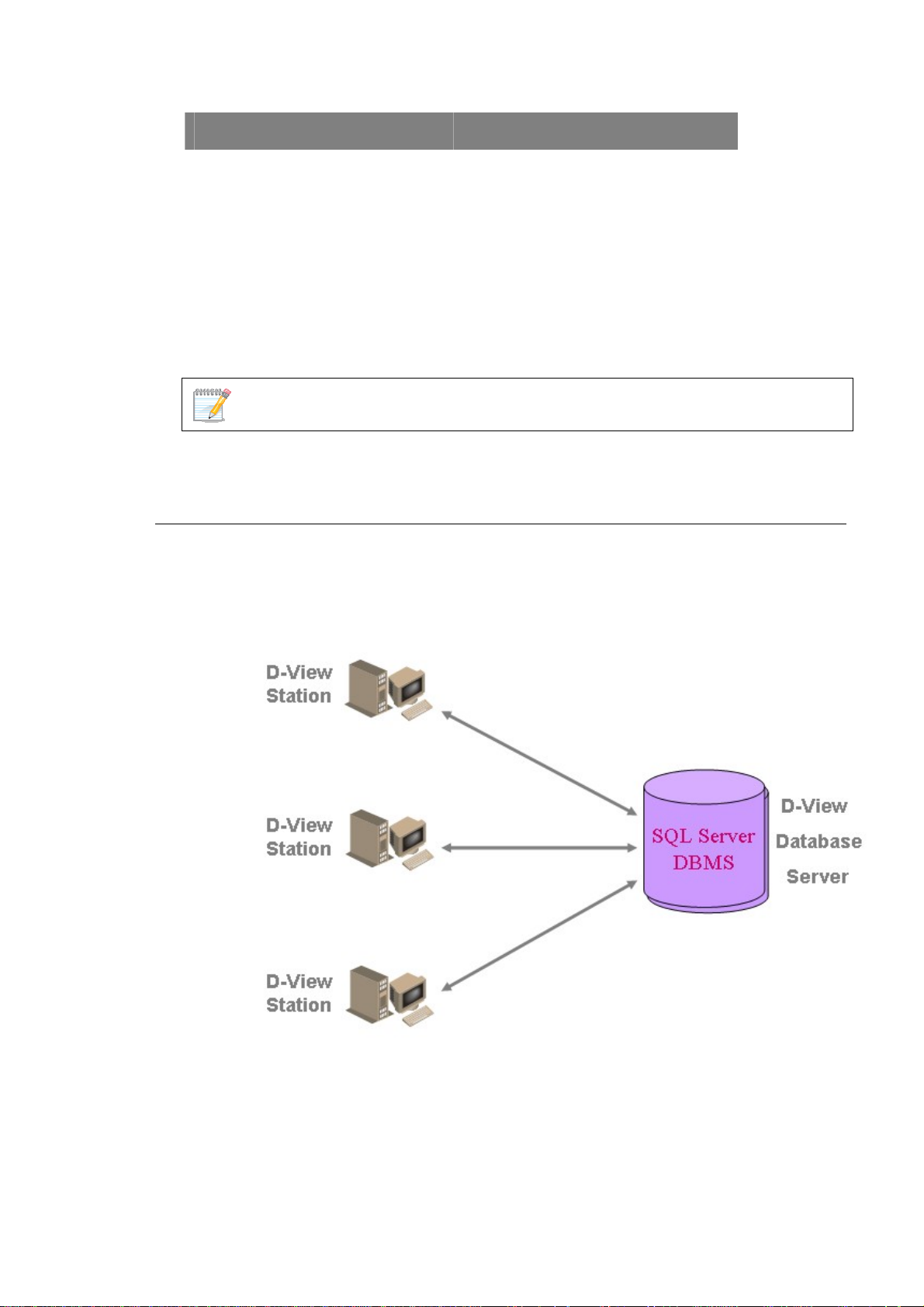
Client-Server Architecture (Professional Edition)
By using the remote access feature of SQL Server, D-View 6.0 Professional
Edition implements Client-Server architecture allowing workstations to share
database information. Given below is an illustration of the SQL Server Remote
Access chart.
Figure 1: SQL Server Remote Access
To configure and connect to the SQL Server database, refer to
and To Create a Database (for Professional Edition).
Steps
Installation
Page 12
Upgrade
To upgrade from D-View 5.1 or earlier versions to 6.0, uninstall all the
programs related to the old version and then re-install the new version.
Download the latest version of the User Manual from dview.dlink.com.tw for the
added new features.
Technical Specifications
MIB Utilities
• Device SNMP Configuration
• MIB II Information and
Statistics
• IF Information Tables
• Spanning Tree Information
and Port Configuration
• Bridge 802.1d Information
and Port Configuration
• RMON Statistic, History and
Event Group
• Transparent Bridge
Forwarding and Static Filter
Tables and Port
• Counter
• 802.1p Priority Configuration
• L3 Utilities
• MIB Browser
• MIB Complier
System Management Tools
• Performance Monitor (switch
should support RFC1213
Interface and RMON)
• Device Panel Simulation
Module
• Batch Program
• Link Capacity Check
• Safeguard Check
• Get All ARP Information
• Device Type Check
• Topology Generator
Security Management Functions
• SNMP v3 covering security
functions such as packet
encryption/decryption, user
levels for different classes of
access right, MPD (RFC
2572), TARGET (RFC 2573),
USM (RFC 2574) and VACM
(RFC 2575)
• SNMP v3 Configuration
• Device Module Access Right
Control
• NMS System Access Control
• NMS System Function
Module Access Right Control
• Local and Radius
Authentication Modes when
Login
Resource Management Functions
• Device Resource Manager
• User Locator
• Device Locator
• User Statistics
• Device Statistics
• Device System Information
Manager (RFC 1213 System)
• Device Port Status Manager
Performance Management Tools
• Performance Monitor
Page 13

• Topology Import / Export
• Hierarchy Topology Manager
• Device Type Extension
• Web Configuration
• Telnet Configuration
• TFTP file transport
• Trac e Rou t e
• MAC Locator
• Ping
Fault Management Tools
• Trap Filter
• Trap L og
• Ping Poll Filter
• Ping Poll Log
• SNMP Poll Filter
• SNMP Poll Log
• Event Config Manager
• Event Viewer
• Port Packet Monitor
Supported Devices
• D-Link Devices:
- SNMP capable
Smart/Managed switches
- OLT/ONU devices
- Wireless bridges and
access points
- SNMP capable routers
- Multi-tenant broadband
CO devices
• Windows Workstation, DC
and Server
• Device Panel Simulation
Page 14

Installing D-View
13
Page 15
INSTALLATION STEPS
To install D-View 6.0 for both Standard and Professional Edition, follow these
procedures:
For Professional Edition:
Prior to installation, ensure the environment on your designated server is
compliant with the software requirements given below:
• Ensure the authentication mode on MS SQL 2000 is Mixed Mode (SQL
Server and Windows) when installing SQL Server. Use Enterprise
Manager for configuration settings.
• Click Microsoft SQL Server > SQL Server Group > Local Windows NT.
• Right-click on Local Windows NT, and select Security.
• Configure Authentication as SQL Server and Windows
1. Insert the CD and navigate to D-View Standard.exe/D-View
Professional.exe. If the installer does not start automatically, start the
installer by double clicking the D-View Standard.exe/ D-View
Professional.exe.
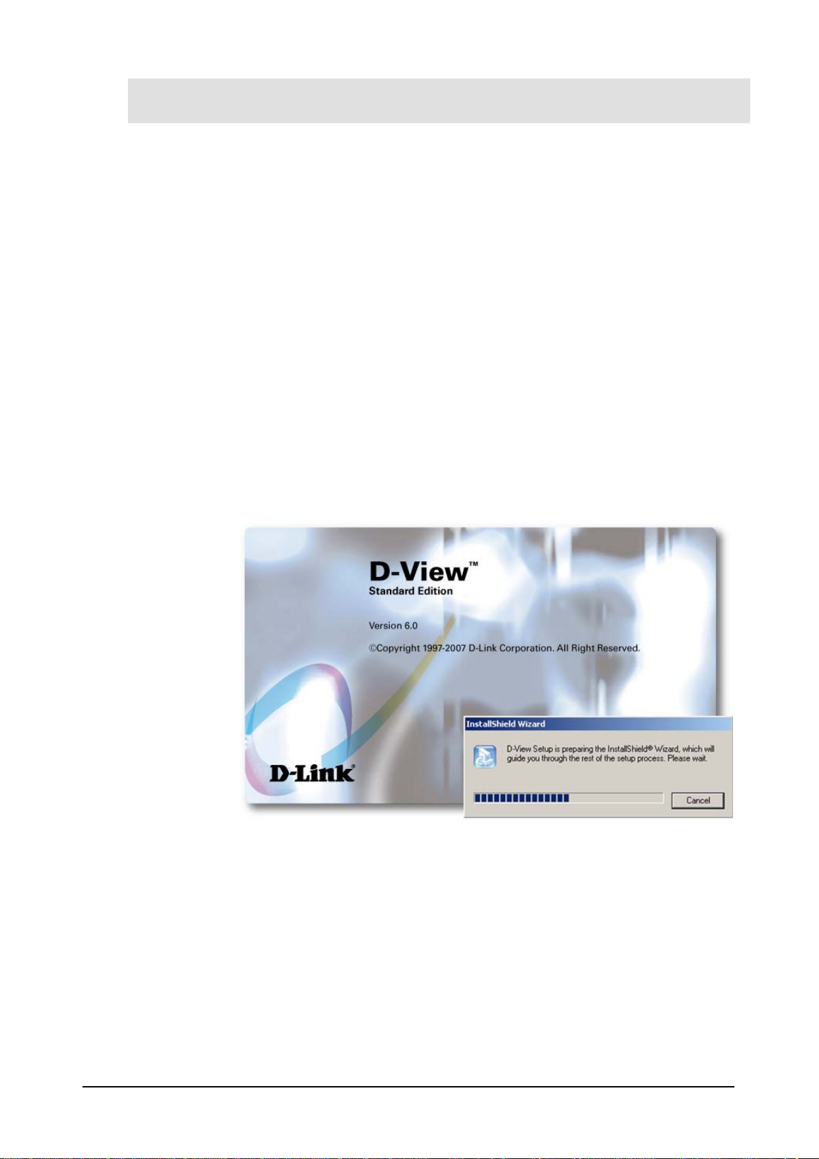
The InstallShield Wizard screen displays.
Figure 2: InstallShield Wizard screen
D-View Setup initiates the InstallShield Wizard, which after loading, will take you
through the installation process.
The License Agreement screen displays.
14
Page 16
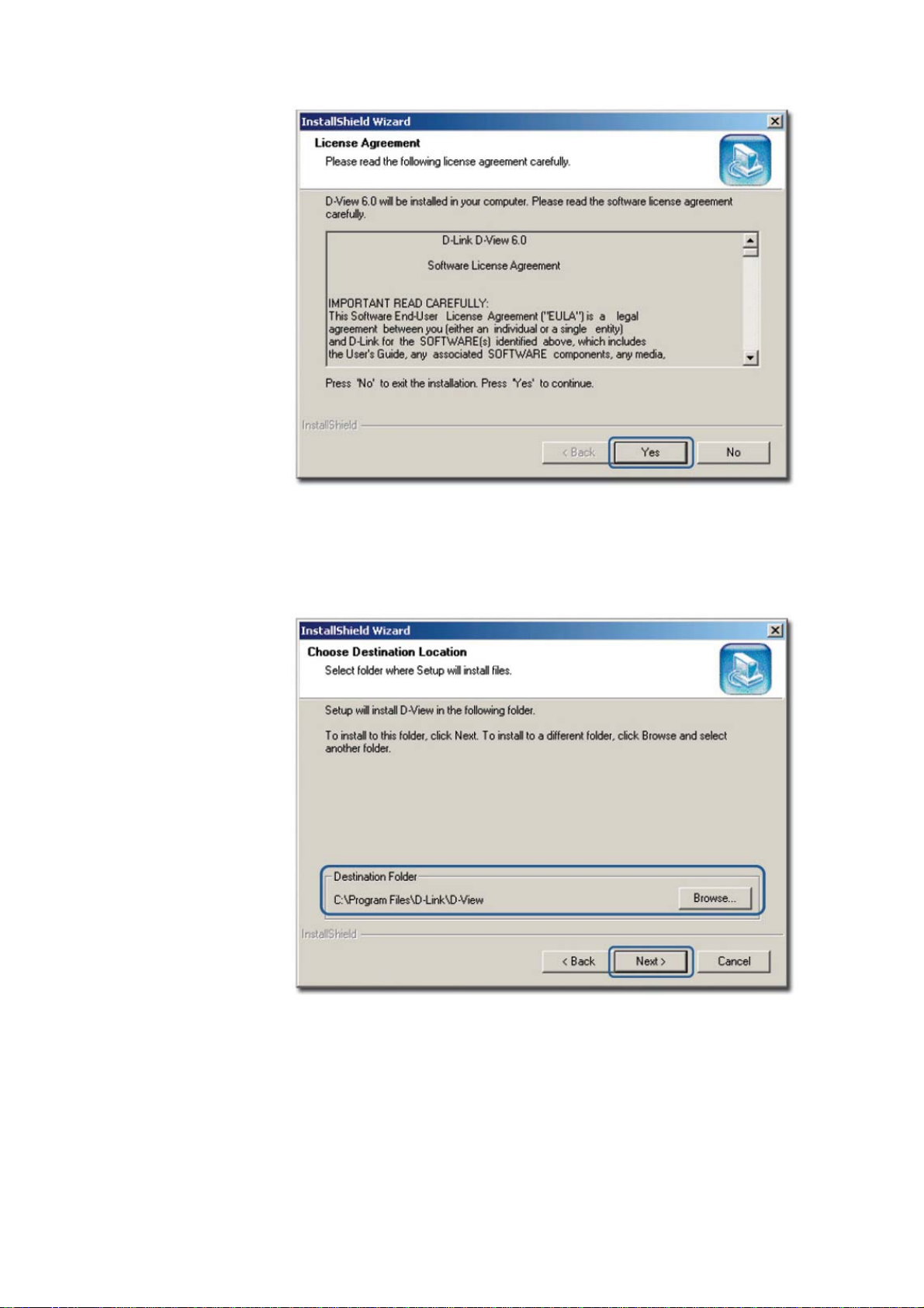
Figure 3: License Agreement screen
2. Click Yes to proceed.
The Choose Destination Location screen displays.
Figure 4: Choose Destination Location screen
3. By default D-View is installed in C:\Program Files\D-Link\D-View.
Alternately, you can choose to install D-View in your preferred designated
folder. Click Browse to select the target location and then click Next to
continue.
The Select Program Folder screen displays.
Page 17

Figure 5: Select Program Folder screen
The Setup will add program icons into the Program Folder.
4. Click Next to continue.
The Start Copying Files screen displays.
Figure 6: Start Copying Files screen
5. Verify the settings before clicking Next. To make changes, click Back.
The Setup Status screen displays.
Page 18
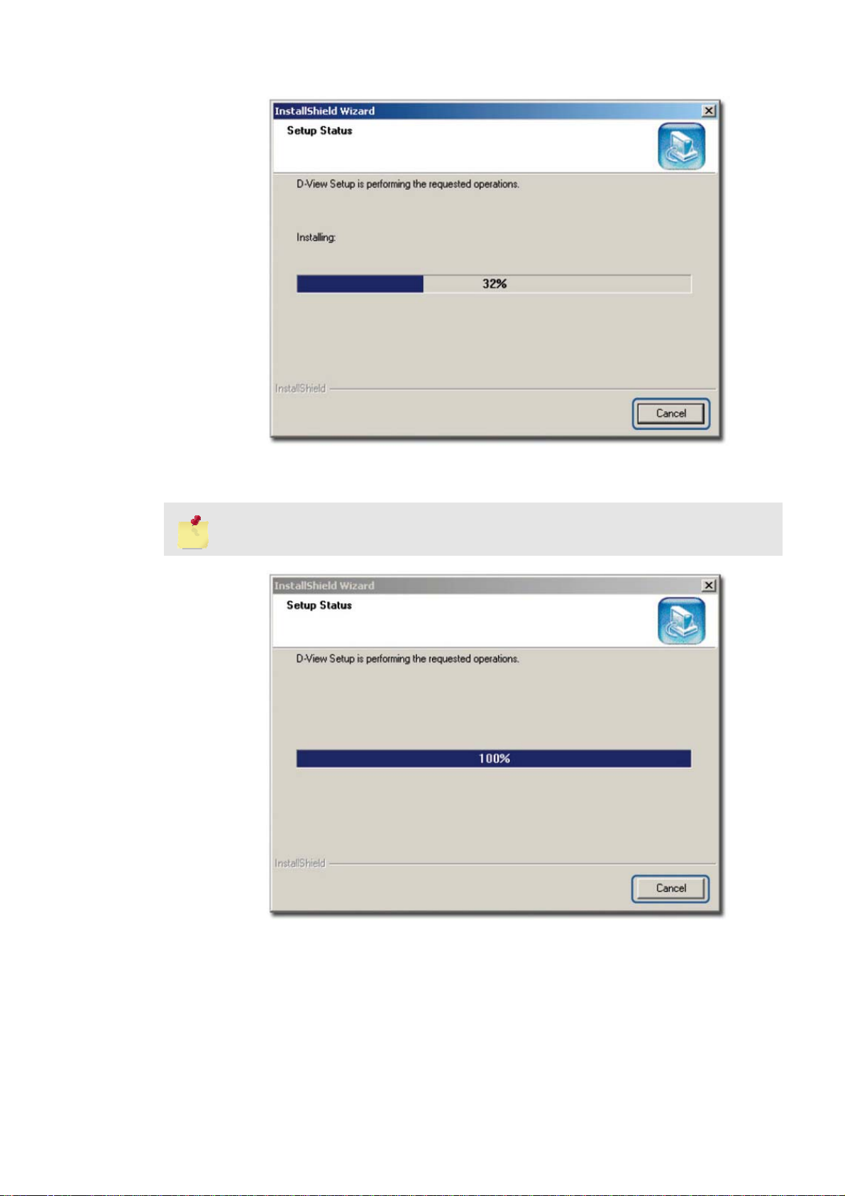
Figure 7: Setup Status screen
6. This screen indicates that D-View installation is in progress.
To stop the installation, click Cancel.
Figure 8: Setup Status screen
Once D-View installation is successfully completed the Welcome to the
Microsoft XML Parser and SDK Setup Wizard window displays.
Page 19

Figure 9: Welcome to the Microsoft XML Parser and SDK Setup Wizard
7. Click Next to continue installing Microsoft XML Parser and SDK on your
server.
The End-User License Agreement screen displays.
Figure 10: End-User License Agreement screen
8. Select I accept the terms in the License Agreement and click Next to
continue.
The Customer Information screen displays.
Page 20
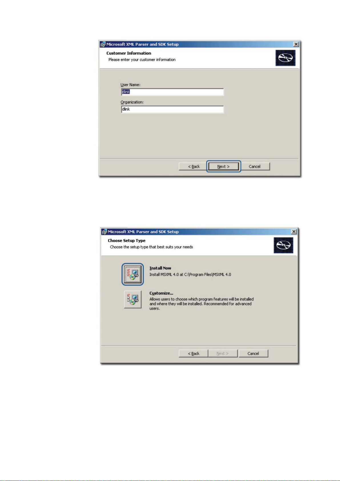
Figure 11: Customer Information screen
9. Enter the User Name and the name of your Organization. Click Next to
continue.
The Choose Setup Type screen displays.
Figure 12: Choose Setup Type screen
10. Use the Customize option to select the program location. Click Install Now
to continue with the installation (recommended).
Page 21
The Completing the Microsoft XML Parser and SDK Setup Wizard screen
displays.
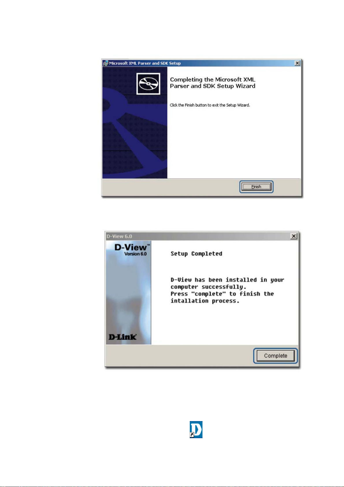
Figure 13: Completing the Microsoft XML Parser and SDK Setup Wizard screen
11. Click Finish to exit and complete the installation.
Figure 14: Setup Complete screen
The screen indicates that D-View 6.0 and Microsoft XML Parser and SDK
software have been installed.
12. Click Complete to close this window.
13. Restart your computer to complete the installation.
14. To start D-View, double click the on the desktop.
Page 22
The Login D-View screen displays. Refer to Getting Started to continue
working with D-View and
D-View 6.0 Licensing to receive the activation code.
To Create a Database (for Professional Edition)
Once D-View and Microsoft XML Parser and SDK software installation is
complete, create a database for D-View.
To create a database, SQL 2000 server must be installed with SQL service
running on the server.
To create a database, follow the steps below:
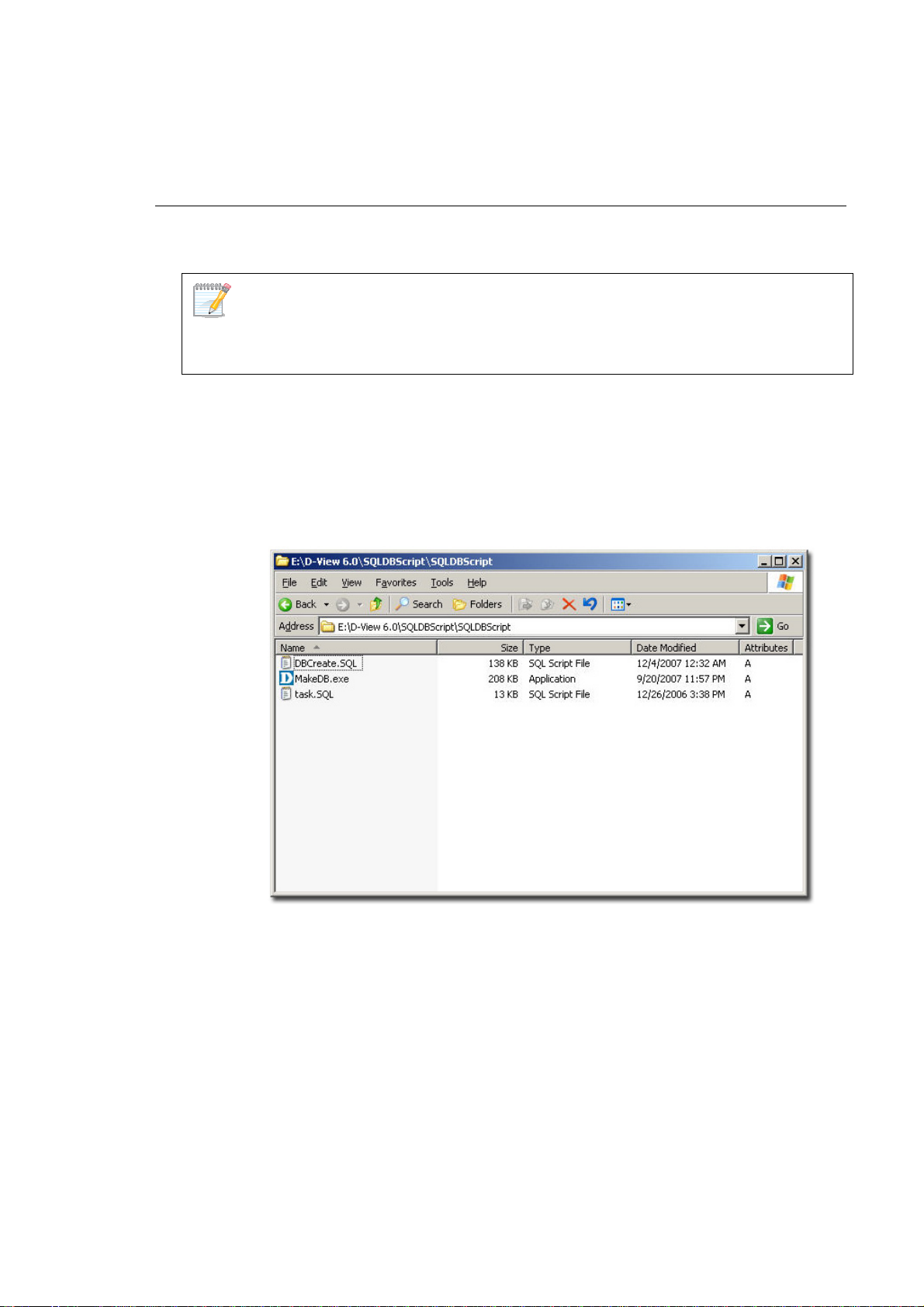
1. Copy the following files to a folder:
• Make DB.exe
• Task.SQL
• DBCreate.SQL
As seen in the following figure, the files are stored in:
E:\D-View 6.0\SQLDBScript\SQLDBScript
Figure 15: MakeDB screen
2. Double-click MakeDB.exe.
The D-View Database Tool window displays.
Page 23
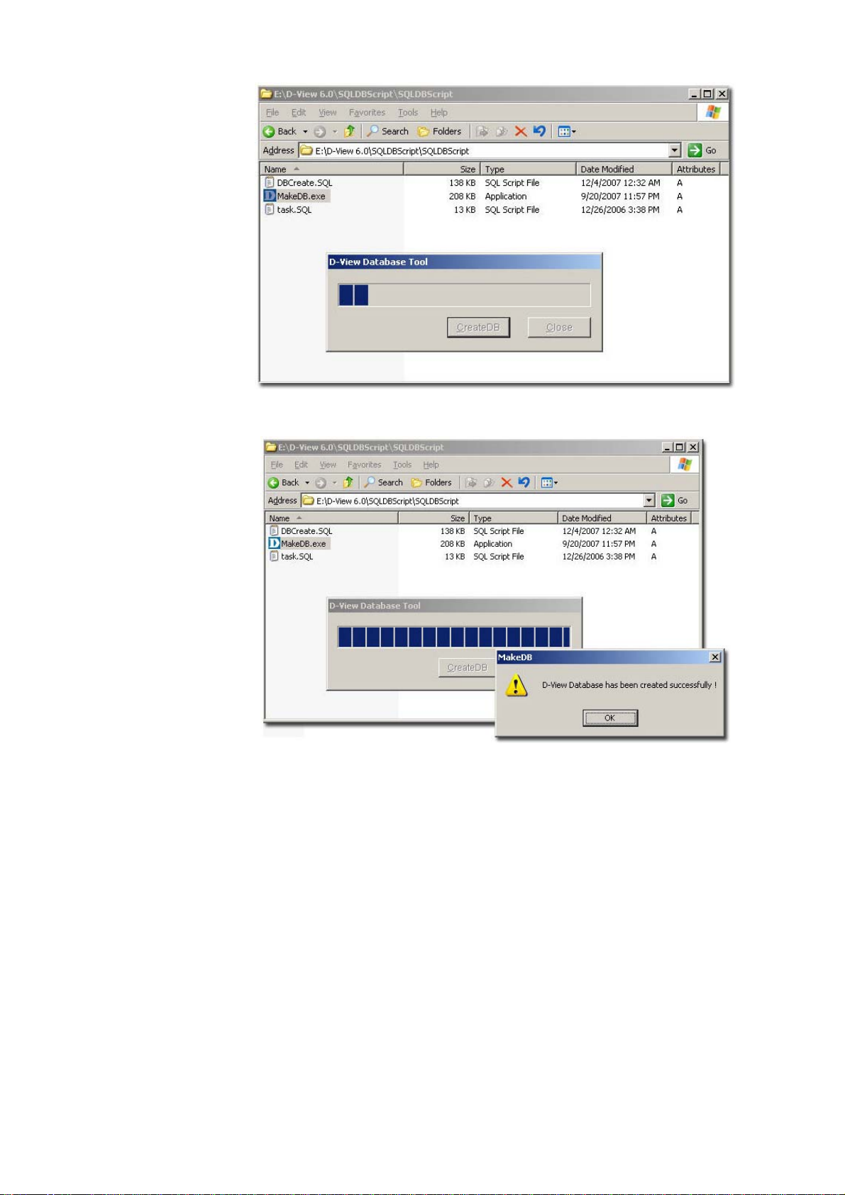
Figure 16: D-View Database Tool screen
D-View Database Tool is in the process of creating a database.
Figure 17: MakeDB screen
3. Click OK to close the window.
4. To edit information in the hosts file, go to:
C:\WINNT\system32\drivers\etc\hosts
Page 24
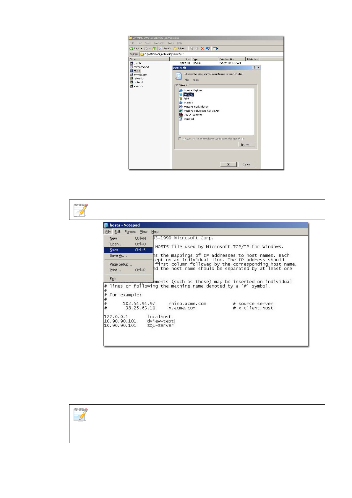
Figure 18: Etc Folder screen
5. Right-click hosts and select Open With. In the Open With window, select
Notepad.
D-Link recommends using notepad to edit the hosts file.
Figure 19: Hosts File screen
6. Update the host file with the following information, for example:
• 127.0.0.1: localhost
• dview-test : 10.90.90.101
• 10.90.90.101: SQL-Server
To implement the client-server architecture, ensure to install D-View 6.0
professional edition in required servers to connect with the SQL database.
7. Click Save to save the file.
Page 25

D-View utilizes SQL-Server alias name to query the SQL database, so therefore
make sure the name entered is the same as the alias name. Ensure to add the IP
address of your server in the hosts file. Check with the system administrator for the
correct IP address of your server.
8. Restart your computer to complete the installation.
The Login D-View screen displays. Refer to
working with D-View.
Getting Started to continue
Page 26
D-VIEW 6.0 LICENSING
Trial Version
When you install D-View, the trial version is automatically installed and allows
you to evaluate the product for a period of 30 days. During this 30-day period,
D-Link recommends you request a permanent license for D-View. For every
single license key obtained, you can run D-View on up to five different
computers.
Skip the Activation step as seen in Figure 19 and continue working with
D-View.
During the trial period, every time D-View is started, a message is displayed
indicating the time remaining before the trial version will expire.
Obtaining the Activation Code
If you opt to buy D-View, there are three ways to request for your activation
code, which are as follows:
OPTION A
To register, go to
such as license key and MAC address of D-View. The license key is provided
with the CD.
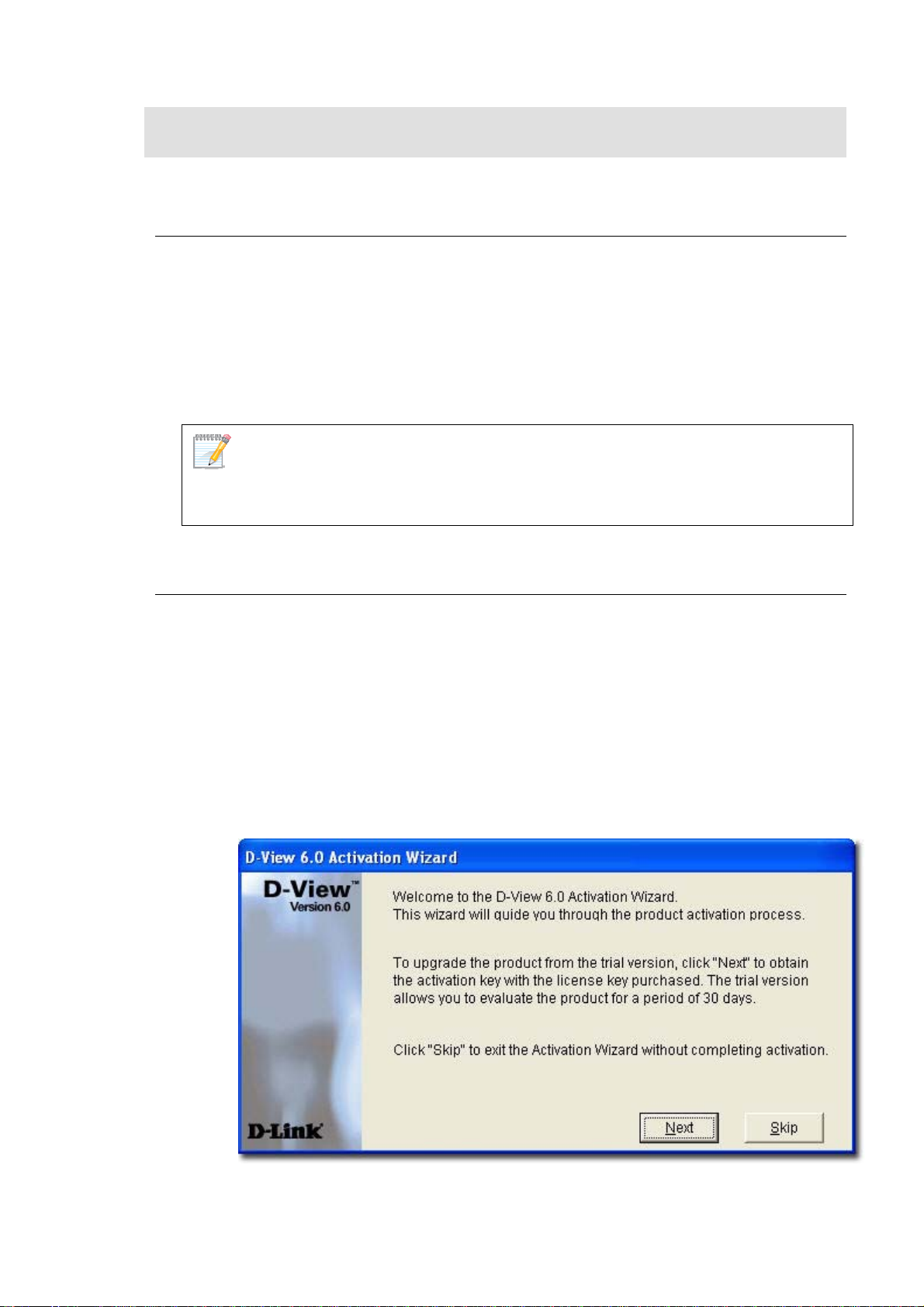
OPTION B
1. Start D-View.
The D-View 6.0 Activation Wizard screen displays.
http://dview.dlink.com.tw and enter user related information
Figure 20: D-View Activation Wizard screen
2. Click Next to continue.
Page 27
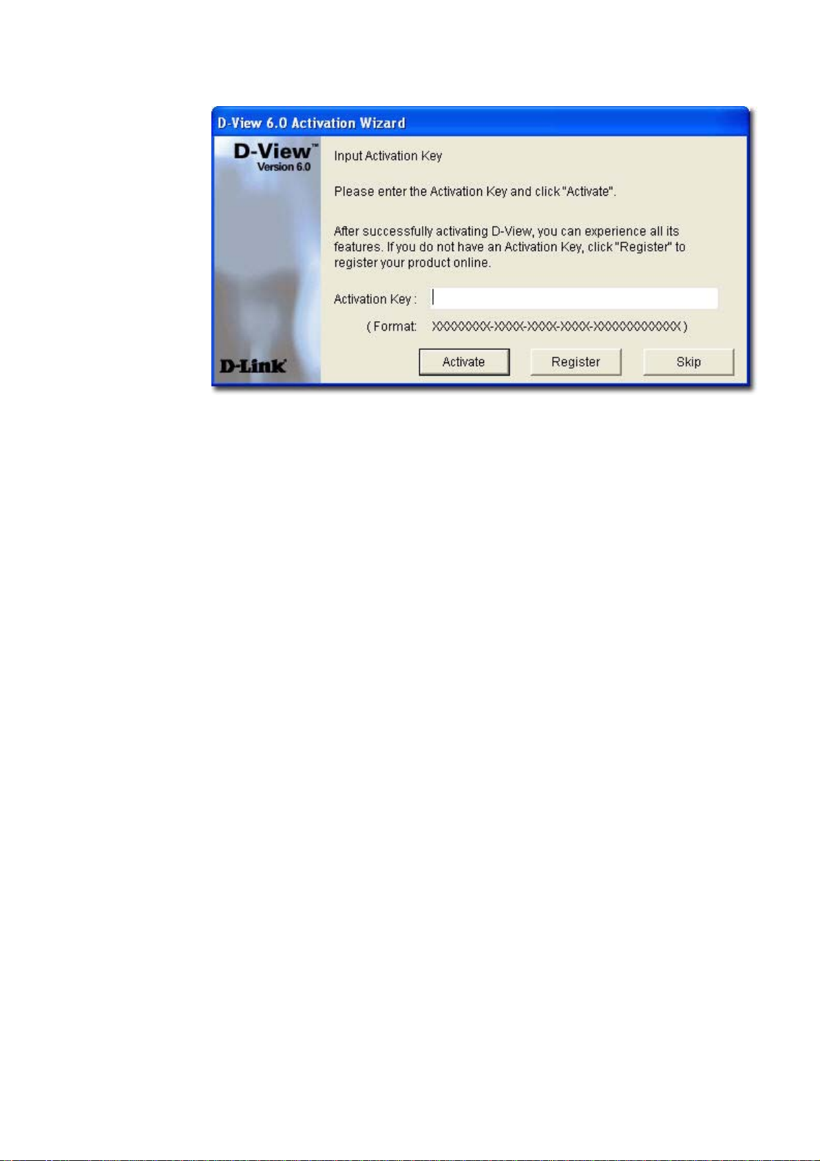
The Input Activation Key screen displays.
Figure 21: Input Activation Key screen
3. Click Register to open the registration website and update the information
on-line.
OPTION C
Start D-View, go to Help>D-View Activation Wizard. Follow the steps
accordingly to register for D-View.
Page 28

Understanding the
Architecture
27
Page 29
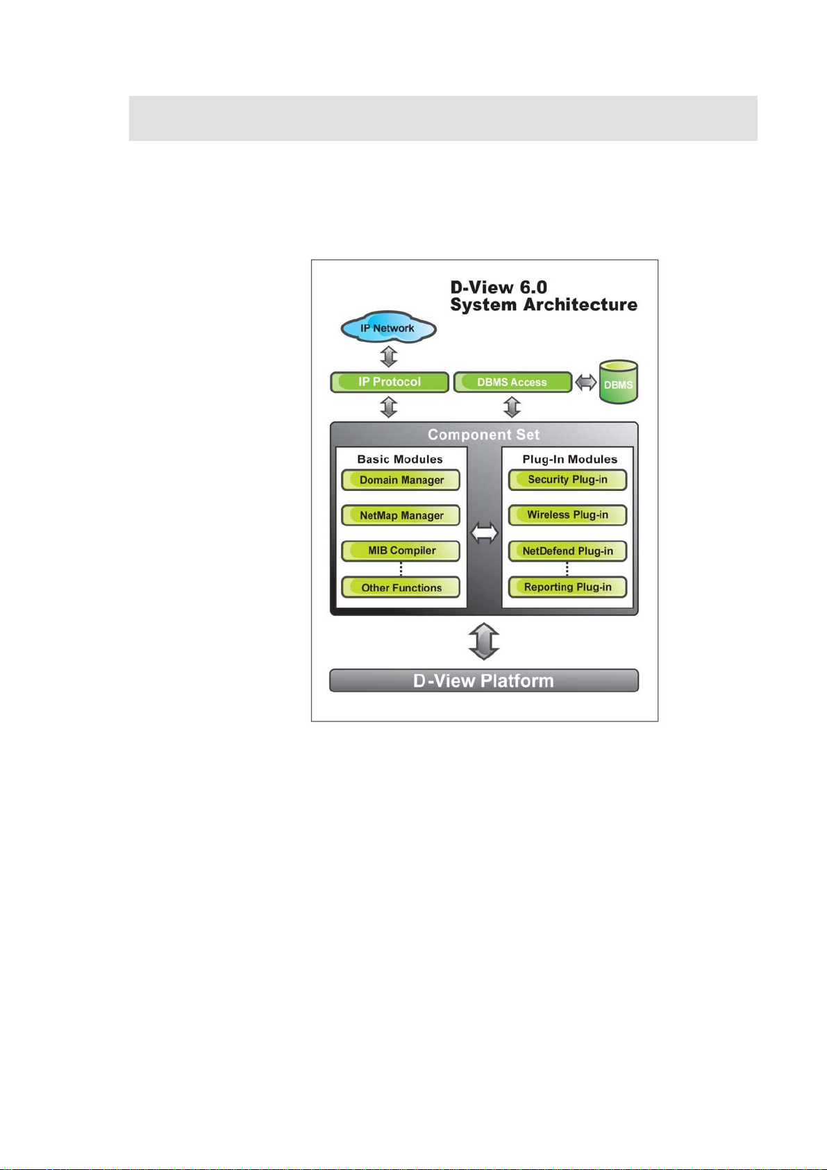
MODULAR ARCHITECTURE
D-View 6.0 is a vendor-independent platform with user plug-in modules. This
new adaptive architecture comprises multiple components such as DBMS
access, basic and plug-in modules.
Figure 22: D-View System Architecture
D-View follows three-tier architecture that is client-server architecture in which
an application is executed by more than one distinct software agent. For
example, an application that uses middleware to service data requests
between a user and a database employs three-tier architecture.
Page 30

FEATURES
With the addition of new features to D-View, Administrators can now:
• Automatically create topology maps of device relationships.
• Graphically represent the real-time status of devices.
• Centrally manage multiple D-Link devices. Administrators can view and
manage multiple devices within the LAN.
• Customize third party devices to integrate with D-View.
• Define trap events using the Trap Editor.
• Manage multiple identical devices at the same time using Batch
Configuration (Firmware updates, Save config, RMON Enable and more).
• Manage third-party devices using the MIB Compiler and MIB Browser.
• Supports SNMPv3 for major MIBs.
• Monitor the status of network devices by polling network devices
periodically.
• View and check the status of the Safeguard Engine from the topology
map.
• Handle events based on severity and notify the users with email or sound
alerts.
Page 31

FUNCTIONS
The following section briefly describes the various functions of D-View:
• New Device Identifier: D-View constantly monitors the network for new
devices. Once a device is plugged in, administrators can add the device into
the topology.
• Database Access Component: Provides interface to access Microsoft
Access and SQL Server 2000/2005 out of the box. If required, functional
components can be changed to access other DBMS such as Oracle or
Sybase.
• Domain Management: D-View allows administrators to categorize
network devices into single or multiple domains.
• Multiple Views: D-View supports tree and list views for viewing devices in
the domain.
• Polling: D-View polls network devices and displays any abnormal behavior
on the Message Board. Devices are polled using ICMP (Internet Control
Message Protocol) or SNMP (Simple Network Management Protocol).
• Performance Management: D-View provides flexible mechanism to
retrieve SNMP OID information. For example, using Performance
Monitor function, the administrator can monitor data ratio per port.
• Syslog Management: Maintain user action log information.
• System Config: Configure global parameters of the network, for example,
Local and Radius Authentication.
• SNMP v3 Support: For major MIBs including MIB II, IF- MIB (RFC2233),
Entity MIB (RFC2737), Bridge 802.1D(RFC1493), RMON, 802.1P (RFC2674)
and 802.1Q (RFC2674).
• Resource Management: Manage, add, or remove network device
resources from/to a topology.
• Device Customization: Include customized network devices by manually
entering device type information.
• Layer 3 Utilities: Layer 3 utilities include IP forwarding, RIP 2 (Routing
Information Protocol), OSPF (Open Shortest Path First), IP MRoute,
DVMRP (Distributed Vector Multicast Routing Protocol) and PIM (Protocol
Independent Multicast) functions for managing switches and advanced
routers in enterprise networks.
• Topology Generator: Create diagrams and schematics for network
design and layout planning.
• Topology Import/Export: Import or export topology information
to/from XML.
Page 32

Understanding the
Interface
31
Page 33

INTRODUCTION
D-View’s user interface provides access to all the views and tools from a single
location.
Figure 23: D-View User Interface
The key interface elements are:
• Domain: A subnetwork comprised of netmaps. Dividing the network into
domains improves performance and security.
• Netmap: A netmap is a graphical representation of your domain/network.
You can also refer to it as a network topology map.
• Menu Toolbar: Access different functional modules from the Menu
toolbar.
• Hierarchical Topology Workplace: Displays a tree-like structure of the
topology.
• Main Toolbar: Use the Main toolbar for quick access of the functional
modules.
• Topology View Window: Displays the net cells that include devices, links
and netmaps.
• Message Board: View event messages of various devices in the domain.
• Advanced Toolbar: Use the Advanced toolbar for quick access of the
functional modules.
• Net Toolbar: Use the Net toolbar for quick access of the functional
modules.
Page 34

• System Toolbar: Use the System toolbar for quick access of the functional
modules.
• Application Toolbar: Use the Application toolbar for quick access of the
functional modules.
• Topo Manager Toolbar: Use the Topo Manager Toolbar for quick access
of the functional modules.
• Status Area: Provides context-sensitive information about the current
state of what you are viewing in the window.
Refer to
Drag and drop the toolbar to rearrange elements around the user interface to suit your
working model
Main Menu for the different functional modules.
Context-sensitive Menus
Most items in D-View have context-sensitive menus. Select an item and then
right-click the mouse to view additional details.
Topology Workspace
Figure 24: Context-sensitive menu accessed from the Topology Workspace
Page 35

Topology View Window
Figure 25: Context-sensitive menu accessed from the Topology View Window
Hierarchy Topology Workspace
Figure 26: Context-sensitive menu accessed from the Hierarchy Topology
Workspace
Page 36

MAIN MENU
D-View’s Main Menu is the entry point for accessing most of the features. It
runs along the top of the screen. This section briefly describes the available
menu options.
File
The following table lists the File menu items and their descriptions.
MENU ITEM DESCRIPTION
Save Save the current topology.
Startup Wizard The wizard guides you to create a
Close Close the current Topology View
Print Print the current topology.
Preview Preview the current topology.
Page Setup Set printer options, properties and
Lockup Locks D-View; only the current user
Logout admin Logout of D-View and sign in as a
Exit Exit D-View.
topology. Refer to
more information.
window.
paper size.
or an administrator can unlock the
system.
different user.
Startup Wizard for
Page 37

View
The View menu enables you to view or hide various D-View Toolbars. The
following table describes the different toolbars.
TOOLBAR DESCRIPTION
Advanced Toolbar
Net Toolbar
System Toolbar
Application Toolbar
Topo Manager Toolbar
Main toolbar
Access Link Capacity
Check, Safeguard Check
and ARP info.
Access Device
Discovery, Trace route,
File Transport, NET
Toolbox, Performance
monitor, MIB browser
and MIB compiler.
Access System Log,
Event Viewer by IP,
Device Group Manager,
Device Event Configure,
System Config,
Administrator
Management, and
Change Password.
Access Batch config,
Run Batch Program,
Topo Export Import,
Device Customization.
Access Select netmap,
Add netmap, Edit
netmap, Delete netmap,
Select device, Add
device, Edit device,
Delete device, Select
link, Add link, Edit link,
Delete link.
Access Save, Copy,
Paste, Print,
Background, Zoom out,
Zoom in, Zoom fit,
Domain Manager,
Configure the devices
want to be polled, Query
the event log by
netmap,
Search the devices in
Page 38

the network and create
a topology
automatically, Upper
Layer, Startup wizard,
Help
Hierarchy Topology workspace Access Main Menu,
Topology, and Message
Board
Message Board Access Message Board
Cascade Cascades the different
topologies one behind
the others
Tile Vertically Arranges the different
topologies one below
the other
Application
The following table lists the Application menu items and their descriptions.
MENU ITEM DESCRIPTION
Batch Config:
• Advanced Option
• Run Batch
Topo Export Import Restore and backup D-View. Refer to
Device Customization Add, modify and delete devices. Refer
Execute a sequence of operations in
D-View. For example, Save
Configuration, Retrieve Port Status,
and so on. Refer to
Configuration
Using Topo Export/Import for more
information.
to
Customizing Devices for more
information.
Batch
for more information.
System
The following table lists the System menu items and their descriptions.
MENU ITEM DESCRIPTION
System Log Store logged events. Refer to System
Log
for more information.
Domain Manager Manage domain information. Refer to
Domain Manager for more
information.
Event Manager
• Event Viewer by
Monitor and manage events. Refer to
Managing Events for more
Page 39

Netmap
• Event Viewer by IP
• Device Group Manager
• Polling Config
• Device Event Config
• Trap Editor
Resource Manager
• MAC Locator
• Device Locator
• User Locator
• Device Collector
• User Statistic
• Device Statistic
System Config Configure the root domain name,
Administrative Manager Create user groups and provide
Change Password Change password after login. Refer to
information.
Locate devices using IP or MAC
address.
management station and
authentication information. Refer to
Login D-View for more information.
access rights for certain functional
modules to an administrator. Refer to
Administrator Manager for more
information.
Changing Password for more
information.
NetTools
The following table lists the NetTools menu items and their descriptions.
MENU ITEM DESCRIPTION
Device Discovery Search devices using IP address.
Refer to
information.
Trace Route Lists all the intermediate routers a
connection must pass through to get
to reach its destination. Refer to
Trac e Rou t e for more information.
TFTP (Trivial File Transfer
Protocol)
NetToolbox Manage devices through Telnet, Web
Upload/Download/Update
configuration files to and from
devices. Refer to
information.
and Ping using the IP address. Refer
to
Device Discovery for more
TFTP for more
Net Toolbox for more information.
Page 40

Port Packet Monitor Monitor the port packet performance.
Refer to
information.
Performance Monitor Monitor the RMON performance of a
device. Refer to
for more information.
MIB Tools
• MIB Compiler
• MIB Browser
Topology Generator Tool to generate a Topology. Refer to
Manage and configure non D-Link
devices. Refer to
with MIB Compiler
information.
Using Topology Generator for more
information.
Port Packet Monitor for more
Performance Monitor
Managing Devices
for more
Advanced
The following table lists the Advanced menu items and their descriptions.
MENU ITEM DESCRIPTION
Link Capacity Check Monitor and modify the link status.
Refer to
for more information.
Device type Check Check the network for new and
updated devices. Refer to
Device Type Check
information.
Safeguard Check Check the safeguard status of
devices. Refer to
Check
All of ARP info Retrieve ARP information from
devices in the topology. Refer to
Retrieving ARP information for more
details.
Monitoring the Link Status
for more
Using Safeguard
for more information.
Help
The following table lists the Help menu items and their descriptions.
Using
MENU ITEM DESCRIPTION
D-View Help Opens D-View online help.
Module supported Displays a list of devices supported
by D-Link.
D-View Activation Wizard Helps you obtain the activation code.
About D-View Displays the About D-View window.
Page 41

Using D-View
Page 42

GETTING STARTED
Before proceeding with this section, D-Link recommends you to get familiar
with the User Interface. Refer to
Login D-View
After successfully installing D-View, type the default Account and Password for
D-View. The default Account is Admin and the default Password is 111111.
Introduction section.
Figure 27: D-View Login screen
Click Option to login to D-View by using different domain-specific
administrator accounts to view different topology maps.
System Configuration
D-View supports two modes of authentication – Local and Radius
Authentication. To configure the root domain name, management station
and authentication information, go to System > System Config.
By default D-View uses Local Authentication.
Figure 28: System Config screen
Page 43

Local Authentication
• The account and password information is stored in the D-View
database.
Radius Authentication
• The information is stored in the Radius server database.
• If the account and password information entered is valid, the server
accepts the authentication and allows the administrator to manage and
monitor the network.
Domain Manager
In a real environment administrators often need to manage multiple domains
of the network. D-View can divide the entire network into many designated
domains for administrators to manage different network.
An administrator needs to create a domain before working on any topology.
When creating a new domain, the administrator should allocate IP address of
the workstation.
Use Domain Manager to create, delete and modify the domain information.
After logging in, D-View, by default, creates a Super Domain and the IP address
of the workstation. A super domain is a virtual domain which manages the
topologies of all the domains. Refer to Creating a Topology to manually create a
topology using Domain Manager.
Startup Wizard
The Startup Wizard helps you create a Topology. The Wizard will
automatically create a new topology based on the information you provide.
To create a topology using the Startup Wizard:
1. Click File> Startup Wizard. The Startup Wizard screen displays.
Page 44
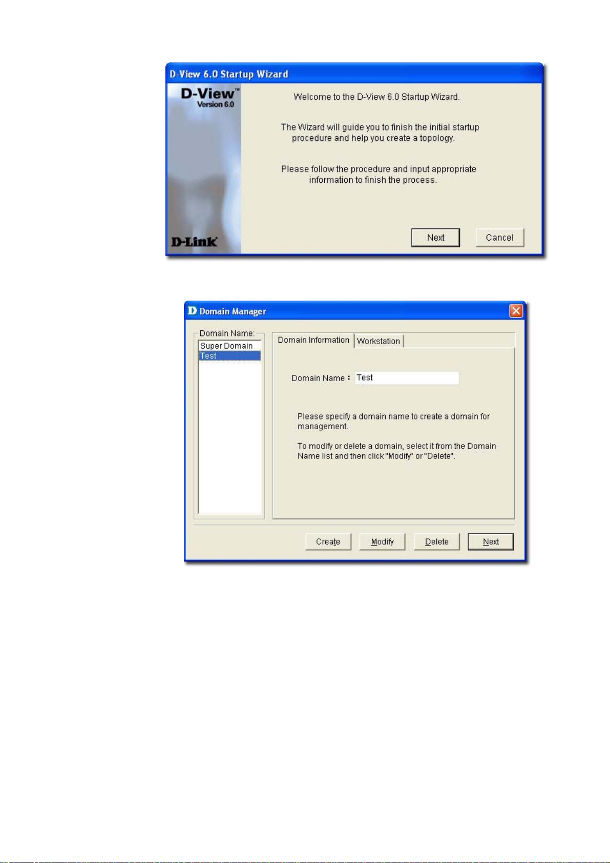
Figure 29: Startup Wizard screen
2. Click Next. The Domain Manager screen displays.
Figure 30: Domain Manager screen
3. Enter the name of your new Domain.
4. Click Next. The Add Netmap screen displays.
Page 45

Figure 31: Add Netmap screen
5. Enter the Netmap Name and Description.
6. Click Next. The Select Network Adapter screen displays.
Figure 32: Select Network Adapter screen
7. Select a network adapter to build the topology.
8. Click OK. The Topology Generator Wizard screen displays.
Page 46

Figure 33: Topology Generator Wizard screen
9. Select either Local Network or Designated Network.
Local Network accesses devices in the local network and Designated
Network accesses devices by specifying the IP range.
10. Enter a name for Topology Generator analysis.
11. Click Next. The Topology Analysis Configuration screen displays.
Figure 34: Topology Analysis Configuration screen
Page 47

12. The topology generator analyzes the local network for the IP address and
subnet mask. The SNMP Community String Setting is by default defined
in D-view.
13. Click Finish to generate the topology. The Topo Export screen displays.
Figure 35: Topo Export screen
14. Click Export to export the generated topology to the Netmap. D-View
displays the status of the export.
After completing the startup wizard’s initial process, you can manage and
monitor devices as described in the following chapters.
Page 48

Working with
Topologies
47
Page 49

CREATING A TOPOLOGY
In D-View there are two ways to create a topology. They are:
• Using Startup Wizard: The wizard guides the users to create a topology.
Refer to
• Create a topology manually
To manually create a topology:
Go to System > Domain Manager and create a new Domain to manage
1.
the topology.
Super Domain is, by default is a virtual domain from which the topologies of all
other, existing domains can be managed.
Startup Wizard create a topology.
Figure 36: Domain Manager screen
2. Create a netmap. To create a netmap, right-click on the domain in the
Hierarchy Topology Workplace, and select Add Netmap.
Page 50

Figure 37: Hierarchy Topology Workplace screen
3. The Add Netmap screen displays.
Figure 38: Add Netmap screen
4. Enter the Name and Description for the Netmap.
5. Click OK.
6.
There are three ways to accomplish the next task. They are:
•
Go to NetTools > Device Discovery to search for and add devices
into the Netmap manually. Then create links betw
Refer to Device Discovery for more information.
the database before you proceed. Make sure to save the changes made to
een the devices.
Page 51

Figure 39: Device Discovery screen
• From the Topo Manager Toolbar, Click Add Devices [ ]. OR use
the Copy/Paste function. Refer to
Copy/Paste for more information.
• Continue to Export your topology. Refer to Using Topo Export/Import
for more information.
Page 52

CREATING ADMINISTRATOR-SPECIFIC TOPOLOGIES
D-View manages the entire topology in domain mode; administrators can
create different topology maps to be managed by different administrators.
Only the administrators in the Super Domain can manage the entire network.
To create multiple topologies with Domain Manager:
1. Login to D-View with Super Domain administrator access.
2. Go to System > Domain Manager and then create two domains. For
example: Domain_1, Domain_2.
Figure 40: Domain Manager screen
3. Select a domain, update the Workstation information and then click
Create to define the management workstation in D-View. For example:
Domain_1, Station_1 and IP address.
Page 53

Figure 41: Domain Manager: Workstation screen
4. Repeat the previous step for the other domain.
5. Create a topology for each domain.
Figure 42: Hierarchy Topology Workplace
6. Login to D-View by using different domain-specific administrator accounts
to view different topology maps. For example: Click Option to login with
Domain_1 administrator account by using Domain_1 Station:
172.231.255.11.
Page 54

Figure 43: Login screen
7. This administrator can view only the Domain_1 topology.
Figure 44: Domain_1 window
Page 55

USING TOPO EXPORT/IMPORT
D-View allows you to export to or import from an XML file. Use this feature to
make regular backups.
To export or import topology information:
1. Go to Application > Topo Export/Import. The Topo Export/Import
screen displays.
Figure 45: Topo Export/Import screen
2. Select either Export or Import.
• Export: Backup/save topology data to an external XML file.
• Import: Restore topology data from an XML file.
3. Select the Domain.
4. Select the Netmap.
5. Browse to select the file to export to or import from.
6. Click Apply.
Refer to
Restoring and Backing Up D-View to restore and backup D-View.
Page 56

TOPOLOGY GENERATOR PRINCIPLE
Using ARP (Address Resolution Protocol) and forwarding table information in
devices, D-View creates a topology for a specific network. The following steps
describe the principle behind the Topology Generator:
1. Discovers the devices by getting the ARP information in devices, and
identifies the relationship among devices by their MAC or IP address.
2. Identifies the device type.
3. Retrieves the forwarding table information in switches to obtain the
relationship among switch ports and MAC address of the devices.
4. Creates a Topology.
The generated Topology can be incorrect if the switches’ forwarding table
information is incorrect or incomplete. The Topology created by Topology
Generator can be considered as a reference in completing the actual topology map.
Page 57

USING TOPOLOGY GENERATOR
Use the Topology Generator to create the topology map.
To use the Topology Generator:
1. Go to NetTools > Topology Generator. The Topology Generator
Wizard screen displays.
Figure 46: Topology Generator Wizard screen
2. Select the Analysis Mode.
3. Enter the Topology Name.
4.
Click Next. The Topology Analysis Configuration screen displays. The
topology generator analyzes the local network for the IP address and
Subnet Mas
in D-View.
k. The SNMP Community String Setting is by default defined
Page 58

Figure 47: Topology Analysis Configuration screen
5. Click Finish to generate the topology. The new topology displays in the
window.
For a designated Network, enter the IP address and ensure that the D-View
management console can access the designated subnet.
Figure 48: Generated Topology window
Page 59

6. Go to Topology > Topo Export or select and right click on the netmap of
the generated Topology to select Topo Export.
Figure 49: Topo Export screen
7. Click Export to export the generated topology.
Page 60

REARRANGING THE TOPOLOGY
Manually rearranging multiple devices and links in a topology is a laborious and
difficult process. But with D-View, you can:
• Rearrange Totally
• Rearrange by step
Using Rearrange Totally
Open and select a device in the topology. Go to Topology > Rearrange
Totally. The system will rearrange the linked devices in hierarchy considering
the selected device as the topmost device.
Using Rearrange by step
Open and select a device in the topology. Go to Topology > Rearrange by
step. The system will rearrange the linked devices in hierarchy considering the
selected device as the top device.
Before Rearranging After Rearranging
Figure 50: Topology before and after rearranging
Page 61

Rolling Back a Topology
After rearranging the topology, you can restore the saved topology that was
created initially from the database.
To Rollback a Topology:
Go to Topology > Topology Rollback. The Topology reverts to the previous
settings. The following screenshots displays the sequence of steps by using the
Topology Rollback function.
Page 62

Figure 51: Sequence of steps displaying the Topology Rollback function
Page 63

Managing and
Monitoring Devices
62
Page 64

IDENTIFYING DEVICES
To view the installed device modules, go to Help > Devices Supported.
Information about all the supported devices is displayed. D-View, by default,
supports all D-Link devices that have been added to D-View.
If you cannot find the device modules in the list, download and install the device
management modules from the D-Link Website.
Figure 52: Devices Supported screen
Refer to Customizing Devices to extend the device module list.
Page 65

MULTI-VENDOR SUPPORT
Only the following modules can be used by third-party devices:
• GenSNMPDeviceModule: D-View recognizes SNMP enabled devices
irrespective of device type, vendor and model number. Refer to
OID of the device
• MIB Browser/Compiler: The MIB compiler translates the MIB from its
normal ASN.1 format to a format that is comprehensible by other
applications. Refer to
information.
• Telnet, Web management tools: Refer to
more information.
• Monitoring performance status by ICMP/SNMP. Refer to
Devices to Poll
• Extension of supported device types with Device Customization
functional module. Refer to
for more information.
Managing Devices with MIB Compiler for more
for more information.
Retrieving
Management Methods for
Setting the
Customizing Devices for more information.
Page 66

CUSTOMIZING DEVICES
D-View provides a flexible method to extend devices that can be identified and
managed by configuring the interface between platform and device module.
To customize devices:
1. Go to Application > Device Customization. The Device
Customization screen displays.
Figure 53: Device Customization screen
2. From the Device Customization screen, you can modify the device type
properties in the dialog.
• Vendor: Select/enter a vendor from the drop-down list.
• Logo: Select a logo for the device module.
• Device Type: Select/enter the device type.
• Max Ports: Enter the maximum number of ports, depending on the
device.
• Alias: Enter an alias name for the device.
• System OID: Enter the OID value of the device. Refer to
OID of the device
• Up, Down, Unpoll icons: Browse to define and customize the device
icons.
• Program: Specify the location of D-View module. Double-click on the
device icon in the topology to manage multiple devices through a
D-View Module (graphic interface).
3. Click Apply to save the Device Type info into the database.
4. Click Refresh to clear the fields.
to obtain the OID of a device.
Retrieving
Page 67

MANAGING DEVICES WITH MIB COMPILER
The MIB Compiler is used for configuring non-D-Link devices, through a MIB
file. The MIB compiler translates the MIB from its normal ASN.1 format to a
format that is comprehensible by other applications. The benefits of using the
MIB compiler are that you can query data and configure the settings for a third
party device with the help of D-View.
To manage devices with MIB Compiler:
1. Go to NetTools > MIB Tools and then select MIB Complier. The D-Link
MIB Compiler screen displays.
Figure 54: D-Link MIB Compiler screen
2. Open the rfc1213 file for modification. D-View loads the compiled MIB file.
Typically, D-View identifies the device type by retrieving the OID value
1.3.6.1.2.1.1.2.0 from the RFC1213 MIB file.
Page 68

Figure 55: Loading compiled MIB Module screen
3. For example, right-click on sysLocation and select Info in the MIB tree.
Figure 56: MIB Tree screen
The Browse Result Node: sysLocation screen displays.
Page 69
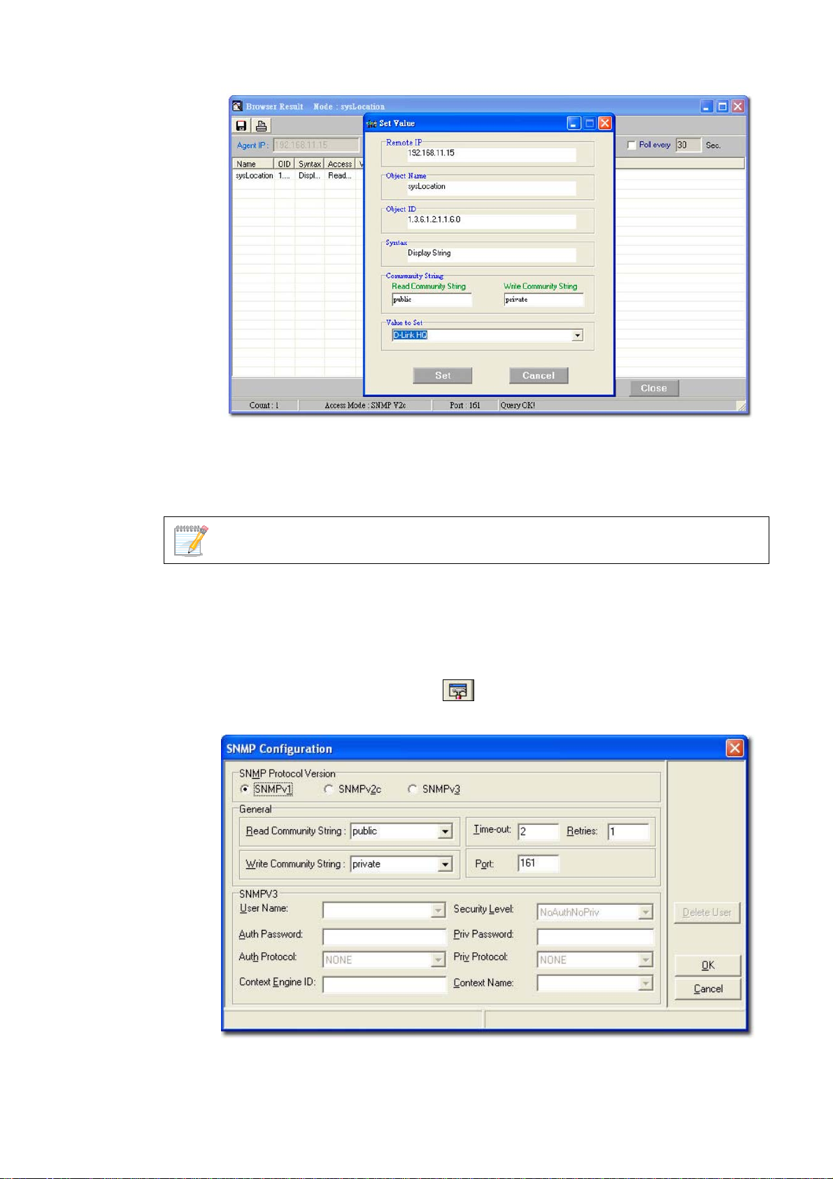
Figure 57: Set Value screen
4. Click Query to get the value of the device.
5. Click Set to set change the value for sysLocation.
6. Make a note of the OID value of the device.
Use MIB Browser to browse MIB files after compilation.
Setting Up SNMP Configuration to Retrieve Device
Information
1. Click SNMP Configuration from the MIB Complier screen. The
SNMP Configuration screen displays.
Figure 58: SNMP Configuration screen
2. Select the SNMP Protocol Version.
Page 70

3. Enter the community string to access devices through SNMP.
If you select SNMPV3, update the SNMPV3-specific fields and access devices
respectively.
4. Click OK and manage the selected device using MIB Compiler.
Page 71

RETRIEVING OID OF THE DEVICE
To identify non D-Link devices, the administrators must first retrieve the OID
of the device and then customize them to add to D-View.
Ensure the device is online to retrieve the OID of the device.
To retrieve the OID of the device:
1. Go to NetTools > MIB Tools > MIB Compiler. The MIB Compiler
screen displays.
Figure 59: MIB Compiler screen
2. Enter the device IP address.
3. Set the SNMP Configuration. Refer to
Retrieve Device Information
4. Compile the RFC1213 MIB File and select sysObjectID from the MIB tree.
5. Right-click sysObjectID and select Info. The Browser Result screen
displays.
6. Make a note of the OID value of the device.
OR
1. For a non-designated device module, D-View will identify the device as
GenSNMPDevice type.
2. Double-click on the device. The graphical interface of the device displays.
3. Go to Device Info and then select System Info. The System
InfoGenSNMPDevice Module screen displays.
from devices.
Setting Up SNMP Configuration to
Page 72
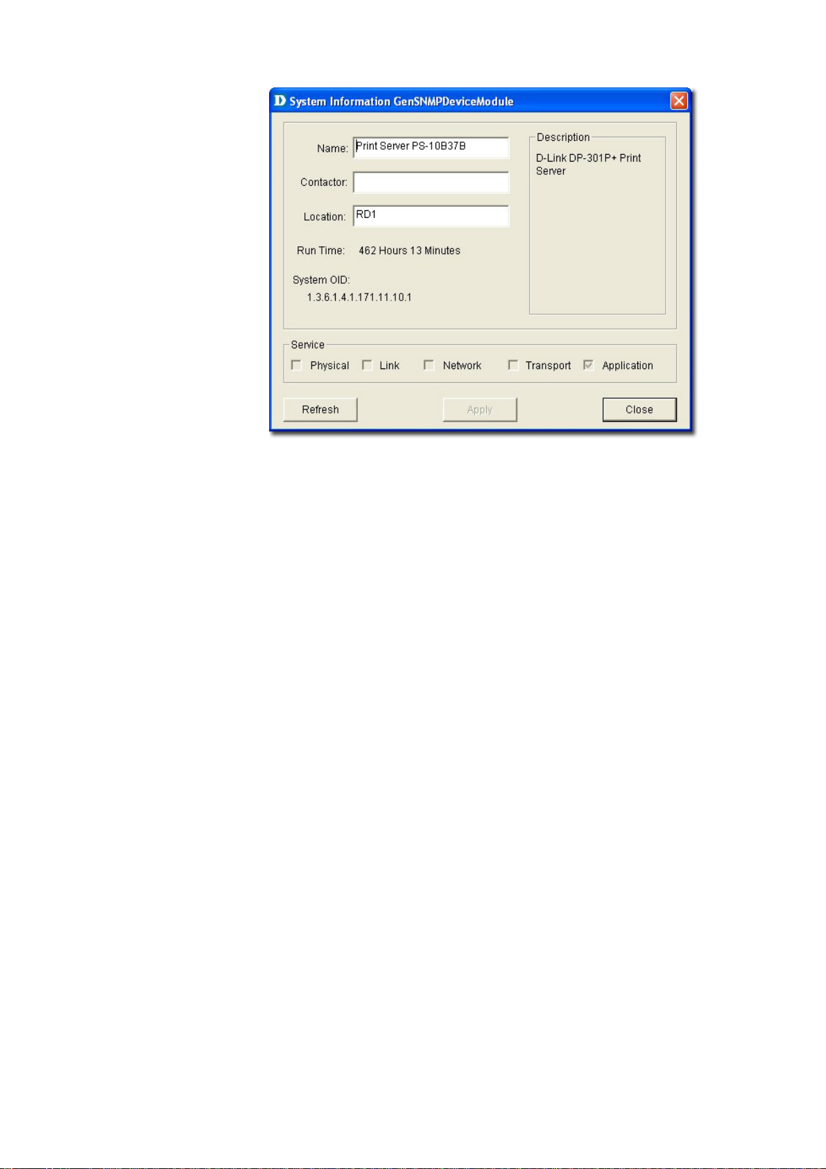
Figure 60: System InfoGenSNMPDeviceModule screen
4. From the System InfoGenSNMPDeviceModule screen, modify the
device type properties in the dialog.
• Name: Enter the name of the device.
• Contactor: Enter the name of the user responsible for managing the
device.
• Location: Enter the location of the device.
• Run Time: Displays the run time of the device.
• Service: Displays the OSI layers the device supports.
5. Click Apply to save the changes.
6. Click Refresh to view the updated information.
Page 73

BATCH CONFIGURATION
The Batch Configuration to o l a l l o w s y o u to exec u t e a s e q u e n ce of operation s
in D-View. For example, Save Configuration, Retrieve Port Status, and so on.
With Batch Configuration you can configure multiple devices simultaneously.
Since all the configurations are similar, only one has been described below.
Remember to configure the OID information before using the Run Batch tool.
To configure the OID information of SafeGuard Engine:
1. Go to Application > Batch Config> Advanced Option. The Advanced
Option screen displays.
Figure 61: Advanced Option screen
2. D-View supports a list of batch function templates. They are:
• FIRM: Download firmware from the switch to the TFTP server or upload
firmware to the device.
• CONFIGURE: Download/Upload config information in the device.
• RESOURCE: Retrieve/Set the information about name, location,
contact of the device.
• PORTSTATUS: Retrieve/Set the Port Enable status.
• SAVE: Save the configuration changes in a device.
• SPANNING: Enable/Disable the STP status in device.
• RMON: Enable/Disable the RMON status in device.
• SAFEGUARD: Enable/Disable the SAFEGUARD status in device.
3. Select SAFEGUARD and then click Next to continue. The Device Type
Config screen displays.
Page 74

Figure 62: Device Type Config screen
4. The devices can be added or deleted to support batch configuration.
5. Click Property to configure the OID properties of a device type. The OID
Config screen displays.
Figure 63: OID Config screen
6. Enter the values of the OID Config information.
7. Enter the values of the OID Value Config for each OID.
• 1 – Other
• 2 – Disable
• 3 – Enable
8. Click Add to configure the OID value of Safeguard Engine.
Page 75

Backup and Update the Devices’ Configuration
Use the Batch tool to backup and update the devices’ configuration.
1. Go to Application > Batch Config > Run Batch or right-click and select
Run Batch from the popup menu after selecting the devices in the opened
topology. The Run Batch screen displays.
Figure 64: Run Batch screen
2. A brief description of other tabs is given below:
• Save: Save device configuration.
• RMON: Enable/Disable RMON status to monitor device
performance.
• Safeguard Engine: Enable/Disable safeguard status. Refer to
Using Safeguard Check for more information.
• Spanning Tree: Enable/Disable the status to prevent undesirable
loops in the network.
• Firmware Update: Upload/download firmware through TFTP
server.
• Resource: Select to update the resource information for a specific
device.
• Config File Manager: Update and backup configuration files from
the TFTP server.
• Port Status: Select to view the port status of the device.
3. Select the Config File Manager tab. The Config File Manager tool helps
the administrators to perform the following actions.
• TFTP Server IP: Enter the IP address on which the TFTP server
program runs.
Page 76

• Operation: Select the mode of operation- Backup or Update.
• TimeOut: SNMP timeout value.
• Run Local TFTP: Select to use the TFTP server tool provided by
D-View. The D-Link TFTP Server screen displays.
4. Click Apply and monitor the running status of the TFTP Server.
Figure 65: D-Link TFTP Server screen
5. The Config File Manager enables uploading of the configuration files to
the device through TFTP server. Administrators can make the required
changes to the file and then upload this file to the device. It reduces the
administrators' time when a similar configuration has to be made to several
similar devices. The status displays OK, when the transaction is
successfully completed. Refer to
TFTP for more information.
Page 77

Using Device Type Check
Use Device Type Check to check the network for new and updated devices.
1. Open the Topology and select the device that needs to be monitored.
Figure 66: Generated Topology window
2. Go to Advanced > Device Type Check. D-View scans the devices in the
open topology.
Figure 67: Device Type Check screen
3. Click Check to manually scan the device.
4. Select one or more devices and click Update. D-View refreshes the
information of the selected devices.
Page 78

Using Safeguard Check
Malicious hosts on the network could attack the Switch through various
methods (for example, packet flooding). To overcome this situation, D-View
uses Safeguard Engine to protect switches from malicious traffic flood. This
minimizes the workload of the switch during the attack. The Switch, therefore,
is capable of forwarding essential packets even during limited bandwidths.
By default, the safeguard status of all devices is disabled.
To configure the safeguard status:
1. Go to Application > Batch Config > Run Batch
Or
In the opened topology select the device and right-click and select Run
Batch.
The Run Batch screen displays. You can now enable or disable the devices’
Safeguard Engine.
Figure 68: Run Batch: Safeguard Engine screen
2. Check the devices and then select ENABLE from the Option drop-down
list.
3. Click Apply to enable the Safeguard Engine status of the selected
devices.
4. Go to Advanced > Safeguard Check for the updated enable status of the
selected devices. The Safeguard Check screen displays.
Page 79

Figure 69: Safeguard Check screen
5. Click Check to manually scan the safeguard status of the device.
6. Click Update to refresh the updated information.
7. Click Close to exit the window.
The Safeguard Engine icon is displayed on the top left-hand corner of the
device in the topology.
Figure 70: Topology indicating the Safeguard Engine enabled for certain switches
The safeguard status is not saved into the database; the status value is only for
the opened topology.
Page 80

Labeling Devices
There are two types of labels in D-View:
• Device Label – Used to label the device. Administrators can set what
details should be displayed.
• Link Label – Used to label the connectors connecting two or more devices.
By default, D-View displays the IP addresses under the device icon in a
topology.
Devic
e Label
To change the Device Label, go to Topology > Device Label and select a
type.
The following table lists the different types of Device Labels.
EXAMPLE DEVICE LABEL DESCRIPTION
Device Name The device name is displayed under the device
icon.
Device IP The device IP address is displayed under the
device icon.
Device Type The device type is displayed above the device
icon.
Safeguard
Engine
Hide Info Hides the information of the devices.
The Safeguard status is displayed on the top le
corner of the device icon. The Safeg
can be checked and updated by calling
Safeguard Check function module.
uard status
Using
ft
Page 81

Link Label
To change the Link Label, go to Topology > Link Label and select a type.
The following table lists the different types of Link Labels.
DEVICE
LABEL
Link Port Displays the port
Link
Speed
DESCRIPTION EXAMPLE
number used to
connected the two
devices.
Displays the maximum
connection speed
between the two
devices.
Editing Device Information
D-View can store device-related information such as name of the device, the
port it uses, interface configuration details, vendor, and so on.
To edit device information:
1. Select the device from an open topology and then go to Topology >
Device Manager > Edit Device. The Edit device screen displays.
OR
Right-click on the device and select Property to edit the properties of the
device. The Edit Device screen displays.
Page 82

Figure 71: Edit Device screen
2. Enter the Basic Information for the device. Basic Information comprises
Name, Vendor, Type, and Description of the device.
3. Configure the Interface IP. Click Add to add a new Interface IP, Edit to
update an existing Interface IP, or Delete to remove an existing Interface
IP.
4. Enter the Detailed Information for the device. Detailed Information
comprises the Location, Buyer, Modules, Serial No., Buy Date, Port
Num, and Firmware of the device.
5. Configure the Management Method. Refer to
more information.
6. Click Apply.
Management Methods
D-View allows administrators to manage multiple device modules
simultaneously, using different management methods. When administrators
need to configure the device, D-View opens the designated management tool.
Management Methods for
Page 83

Figure 72: Device Management Method screen
D-View includes the following methods for managing a device:
• SNMP v1/v2c: D-View will use device modules that support SNMP v1/v2c
to manage the device.
• SNMP v3: D-View will use device modules that support SNMP v3 to
manage the device.
• TELNET: D-View will use the telnet tool embedded in the OS to manage the
device.
• WEB: D-View will use web browser (IE) tool imbedded in the OS to manage
the device.
• Customize: D-View will use the designated program to manage the
device.
Page 84

MANAGING EVENTS
Events are one of the core functions of D-View. In fact, the main function of
D-View can be described as detecting changes within the network, and every
change can be thought of as an event. The following sections will discuss
Events in detail.
Setting Poll Parameters
Parameters for the polling include poll interval and poll timeout.
To set the Polling Parameters:
1. Go to System > Event Manager > Polling Config > Set Parameter tab.
Figure 73: Set Parameter screen
2. Set the Poll Interval in seconds. D-View polls the devices at the set time
interval.
3. Set the Poll Timeout in seconds. D-View stops polling the device after the
timeout period.
4. Click Apply.
Page 85

Setting the Devices to Poll
To monitor the status of the devices, add the devices to the poll list. You can
also delete the devices if you no longer want to monitor the device status.
When the devices are added to the Poll list, the device icon color changes from
grey to green.
To configure the Poll List:
1. Go to System > Event Manager > Polling Config > Select Poll Device
tab.
Figure 74: Select Poll Device screen
2. Select the Device Group. Refer to Grouping Devices using Device Manager
for more information on grouping devices.
3. Select the Poll Protocol. The two options to poll the network devices
periodically are SNMP (Simple Network Management Protocol) and ICMP
(Internet Control Message Protocol). The default poll protocol is ICMP.
4. Select devices and then click Add to Poll to add to the poll list.
From the topology, select the device and right-click to select Add to Poll List or
Delete from Poll List from the popup menu.
Page 86

By default, when the topology is imported, the devices are in an unpoll status.
The status of the device is changed to Up or Down when the device is added
ma anu lly.
Viewing the Poll Device List
The Poll Device List displays the list of devices after generating the Topology.
1. Go to System > Event Manager > Polling Config > Poll Device List
tab.
Figure 75: Poll Device List screen
2. From here you can delete devices you’ve added to the list.
From the topology, select the device and right-click to select Add to Poll List or
Delete from Poll List from the popup menu.
Grouping Devices using Device Manager
For monitoring similar devices, you can group devices of the same type using
the Device Group Manager.
1. Go to System > Event Manager > Device Group Manager. The Device
Group Manager screen displays.
Page 87

Figure 76: Device Group screen
2. Click Add Group to create a group. The Add Group screen displays.
Figure 77: Add Group screen
3. Enter the name of the Group.
4. Enter a brief Description of the group.
5. Click Add. The group is created.
6. Next, select devices from the device list you want to add to this group and
click Add To Group. The Add Device to a group screen displays.
Page 88

Figure 78: Add device to group screen
7. Select the group from the list.
8. Click Add. The devices are added to the group.
Figure 79: Device Group screen
9. Click Set Community to change the read/write community of devices.
Configuring Device Events
After defining the poll list, configure the event process mechanism for a device
or a group of devices when an event occurs.
Page 89

To configure Device Events:
1. Go to System > Event Manager > Device Event Config. The Event
Configuration screen displays.
Figure 80: Event Configuration screen
2. Select a Device Group or a Device Name.
3. Select the Type of event. The different events are:
TRAP INDICATION
Up -> Down The link between the device and the workstation
(D-View) is disconnected.
Down -> Up The link between device and the workstation is
connected.
Cold Start Device sends Cold Start trap message when the
device is powered off/on.
Warm Start Device sends Warm Start trap message when
the device has been rebooted.
Link Down Device sends Link Down trap message when the
status of an attached communication interface
has changed from up to down.
Link Up Device sends Link Up trap message when the
status of an attached communication interface
has changed from down to up.
Device
Authentication Fail
EGP Fail In routers running the Exterior Gateway
Device sends Authentication Fail trap when the
agent received a request from an unauthorized
manager.
Protocol (EGP), an EGP Neighbor has changed
to a down state.
Page 90

Self-Defined Trap Device sends the private trap defined by the
users.
Threshold Event Device sends the trap message, when D-View
detects a threshold event. Whenever the
exceeded count reaches the trigger value then a
threshold event is generated.
4. Enable Filter this type event if you do not want to notify users of this
event.
5. Set the notification options as required:
• Sound: D-View plays the selected sound file or beeps to notify users that
an event has occurred.
• Log: Saves the event into database. Set the color of the Log messages
displayed in the message board.
• Flash: The netmap icon in the Hierarchy Topology Workplace will flicker a
warning sign.
• EMail: D-View notifies administrators of an event through an e-mail.
• Mail Server Config: Click to configure the mail.
Figure 81: Email Configuration screen
o Sender: Update the Sender’s information by entering the name, email,
authority, account and password.
o SMTP Server: Enter the IP address of the device. SMTP is a server
program that lets you send email messages directly from your
computer.
o SMTP Port: Enter the SMTP Port number to connect to the server.
o Click Test to connect to the mail server.
Page 91

Retrieving Device Event Logs
D-View saves all events into the database a s and whe n th e y oc cur . Re t rie ve t he
Device Event Log to view event information.
1. Event Viewer by Netmap: To view events occurred for a selected Netmap
go to System > Event Manager > Event Viewer by Netmap.
Figure 82: Event Viewer by Netmap screen
2. Event Viewer by IP: To view events occurred for a selected IP address go
to System > Event Manager > Event Viewer by IP.
Figure 83: Event Viewer by IP address screen
Page 92

3. From here, you can further filter the events. Select from the following to
filter the events:
o Filter Setting: Administrators can set filters such as event type and
level of severity.
o Device: Select device information such as the IP address, vendor name
and device type from the drop-down list.
o Time: Set the time interval at which the event has occurred.
o Event Source: Select the source of the event saved in the database or
stored in a file.
4. Save the settings and click Query to query the database and a list of
devices are displayed depending on the filter setting.
5. Click Statistic to view event statistics by event type, manufacturer,
severity and device type.
Figure 84: Event Statistics: Bar Chart screen
Bar Chart: Illustrates the event statistics by Evo ent Type,
Manufacturer, Severity and Device Type.
Page 93

Figure 85: Event Statistics: Pie Chart screen
o Pie Chart: Illustrates the event statistics by Event Type,
Manufacturer, Severity and Device Type.
Defining Trap Information
D-View monitors device events by polling devices by sending ICMP or SNMP
packets positively and using Trap Editor to retrieve trap information
passively.
D-View retrieves and parses trap information from devices. In order to receive
and parse the private trap information from a designated device,
administrators need to customize the private trap information.
To customize the trap information, retrieve the definition format from the device
vendor.
To define trap information:
1. Go to System > Event Manager > Trap Editor. The Trap Editor screen
displays.
Page 94

Figure 86: Trap Editor screen
2. Check By Device Type to select the Vendor name and Device Type from
the drop-down list.
3. Enter the Enterprise OID. Contact D-Link support to obtain the trap OID.
4. Enter the Specific Num. The Specific Num associates with the specific
trap action. The Enterprise OID and the Specific Num define the
designated type of trap.
5. Type the Description of the message, for the designated trap.
For example:
The enterprise OID is 1.3.6.1.2.1.10.166.11
The specific number 6 here represents
mplsL3VpnNumVrfRouteMaxThreshCleared trap message.
Locating the Switch Port
D-View provides an easy and effective way to inspect and report which network
devices are connected to each switch port. Therefore it solves the problem of
having to trace cables in order to see which port a network device is connected
to, making it a very valuable tool for network and IT administrators.
Locate the switch port of the end user’s computer with the MAC or IP address
using MAC Locator.
1. Go to System> Resource Manager > MAC Locator. The Mac Locator
screen displays.
Page 95

Figure 87: MAC Locator screen
2. Enter the MAC or IP address. Click Locate.
D-View locates the specified device, if found.
Figure 88: Specified device located in the Topology using MAC Locator
Page 96
Monitoring the Link Status
D-view lets you monitor and modify the link status in a topology.
To monitor the Link Status:
1. Open the topology.
2. Go to Topology > Link Label and then select Link Speed. The status of
the links is displayed.
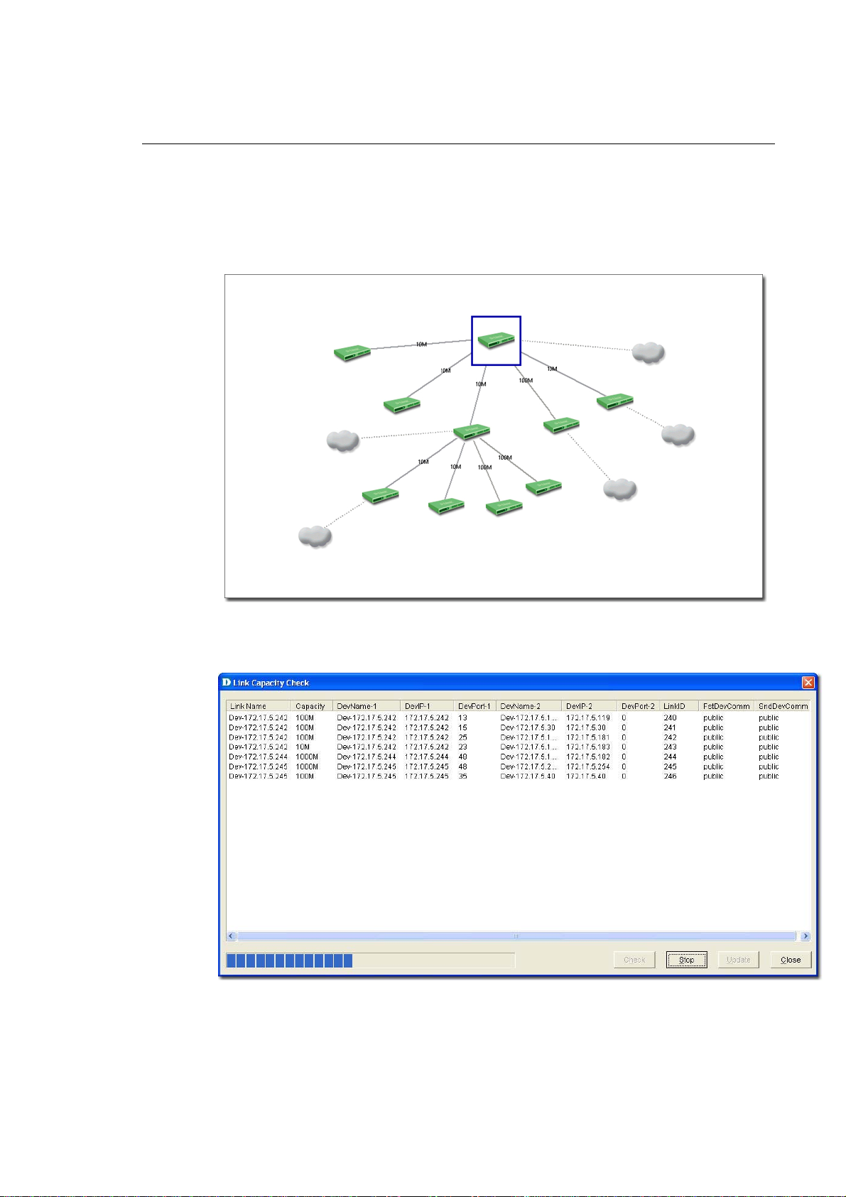
Figure 89: The Topology displays the Link status of the devices
3. Go to Advanced > Link Capacity Check, to monitor the link status of all
the devices in a table.
Figure 90: Link Capacity Check screen
4. Click Check. D-View checks the capacity of each device link port and
displays the minimum capacity value of the link as seen in figure below.
Page 97

Figure 91: The Topology displays the link status after the Link Capacity check
By default, the link capacity is 100M when a link is created between devices.
To modify the Capacity Value:
1. Go to Topology > Link Manager > Edit Link. The Edit Link screen
displays.
OR
In a topology, right-click on a link and then select Property. The Edit Link
screen displays.
Figure 92: Edit Link screen
2. Update the Capacity. Select from 10M, 100M, 1000M, or 10G.
3. Click OK.
In order to obtain accurate results from the link capacity, ensure the port
numbers between the devices are entered correctly.
Page 98

Locating Devices
In D-View, you can locate devices using the Device Locator tool. Use Device
Locator to find devices in multiple topologies by entering the Device Name or
IP address.
1. Go to System > Resource Manager > Device Locator. The Device
Locator screen displays.
Figure 93: Device Locator screen
2. Enter the name or IP address of the device to be located.
3. Click Search to locate the device. The results are displayed.
4. Click Open Topo to locate the device in a topology.
Page 99

Figure 94: The Topology indicates the device located after using Device Locator tool
Entering User Information
In D-View, you can use the Device Collector tool to enter User Information.
To enter user information:
1. Go to System > Resource Manager > Device Collector. The Device
Collector screen displays.
2. Use filter options to select the vendor’s name and device type. A list of
devices is displayed.
Figure 95: Device Collector screen
Page 100

3. Select a device from the list and then click User Info. The User Info
screen displays.
Figure 96: User Information screen
4. Add/Edit/Delete user information of the selected device.
Locating Users
In D-View, you can locate users using the User Locator tool. Use User
Locator to find users connected with a particular device.
To Locate Users:
1. Go to System > Resource Manager > User Locator. The User Locator
screen displays.
Figure 97: User Locator screen
2. Enter the user’s name. Separate multiple entries with a comma (,).
3. Click Search. The search results are displayed.
4. Click Open Topo to locate the device in a topology.
 Loading...