

Page 1

DSL-2730E
User Manual
Page 2

User Manual
Contents
1 Introduction ........................................................................................................ 1
1.1 Safety Precautions ................................................................................ 1
1.2 LEDs and Interfaces .............................................................................. 1
1.3 System Requirements ........................................................................... 3
1.4 Features ................................................................................................ 3
2 Hardware Installation ......................................................................................... 5
3 About the Web Configuration ............................................................................. 7
3.1 Access the Router ................................................................................. 7
3.2 Status ..................................................................................................... 8
3.3 Setup ................................................................................................... 10
3.3.1 WAN Configuration ................................................................... 13
3.3.1.1 WAN .............................................................................. 13
3.3.1.2 Automatically PVC ........................................................ 18
3.3.1.3 ATM Setting................................................................... 19
3.3.1.4 ADSL Setting ................................................................. 20
3.3.2 LAN ........................................................................................... 21
3.3.2.1 LAN ............................................................................... 21
3.3.2.2 DHCP ............................................................................ 23
3.3.2.3 DHCP Static .................................................................. 27
3.3.2.4 DHCP Filter ................................................................... 28
3.3.2.5 LAN IPv6 ....................................................................... 29
3.3.3 WLAN ....................................................................................... 31
3.3.3.1 Basic Settings ............................................................... 31
3.3.3.2 Security ......................................................................... 33
3.3.3.3 Multi-BSSID .................................................................. 36
3.3.3.4 Access Control .............................................................. 38
3.3.3.5 Advanced ...................................................................... 38
3.3.3.6 WPS .............................................................................. 40
3.4 Advanced ............................................................................................. 41
3.4.1 Route ........................................................................................ 42
3.4.1.1 Static Route ................................................................... 42
3.4.1.2 IPv6 Static Route .......................................................... 43
3.4.1.3 RIP ................................................................................ 44
3.4.2 NAT ........................................................................................... 46
i
Page 3

User Manual
3.4.2.1 DMZ .............................................................................. 46
3.4.2.2 Virtual Server ................................................................ 46
3.4.2.3 ALG ............................................................................... 48
3.4.2.4 NAT Exclude IP ............................................................. 48
3.4.2.5 Port Trigger ................................................................... 49
3.4.3 QoS ........................................................................................... 51
3.4.4 CWMP ...................................................................................... 53
3.4.5 Port Mapping ............................................................................ 55
3.4.6 Others ....................................................................................... 60
3.4.6.1 Bridge Setting ............................................................... 60
3.4.6.2 Client Limit .................................................................... 61
3.4.6.3 Tunnel ........................................................................... 61
3.4.6.4 Others ........................................................................... 63
3.5 Service ................................................................................................. 63
3.5.1 IGMP ......................................................................................... 63
3.5.1.1 IGMP Proxy ................................................................... 64
3.5.1.2 IGMP MLD .................................................................... 64
3.5.2 UPnP ........................................................................................ 65
3.5.3 SNMP ....................................................................................... 65
3.5.4 DNS .......................................................................................... 66
3.5.4.1 DNS .............................................................................. 67
3.5.4.2 IPv6 DNS ...................................................................... 67
3.5.5 DDNS ........................................................................................ 68
3.6 Firewall ................................................................................................ 69
3.6.1 MAC Filter ................................................................................. 70
3.6.2 IP/Port Filter .............................................................................. 70
3.6.2.1 IP/Port Filter .................................................................. 70
3.6.2.2 IPv6/Port Filter .............................................................. 71
3.6.3 Parent Control........................................................................... 73
3.6.4 ACL ........................................................................................... 74
3.6.4.1 ACL ............................................................................... 74
3.6.4.2 IPv6 ACL ....................................................................... 77
3.6.5 DoS ........................................................................................... 80
3.6.6 MAC Spoofing ........................................................................... 81
3.7 Maintenance ........................................................................................ 82
3.7.1 Update ...................................................................................... 82
ii
Page 4

User Manual
3.7.1.1 Firmware Update .......................................................... 82
3.7.1.2 Backup/Restore ............................................................ 83
3.7.2 Password .................................................................................. 84
3.7.3 Reboot ...................................................................................... 85
3.7.4 Time .......................................................................................... 85
3.7.5 Log ............................................................................................ 87
3.7.6 Diagnostics ............................................................................... 87
4 Q&A .................................................................................................................. 88
iii
Page 5

User Manual
1 Introduction
The device supports multiple line modes. It provides four 10/100 base-T Ethernet
interfaces at the user end. The device provides high-speed ADSL2+ broadband
connection to the Internet or Intranet for high-end users, such as net bars and
office users. It provides high performance access to the Internet.
The device supports WLAN access, such as WLAN AP or WLAN device, to the
Internet. It complies with IEEE 802.11, 802.11b/g/n specifications, WEP, WPA, and
WPA2 security specifications.
1.1 Safety Precautions
Follow the following instructions to prevent the device from risks and damage
caused by fire or electric power:
Use volume labels to mark the type of power.
Use the power adapter packed within the device package.
Pay attention to the power load of the outlet or prolonged lines. An
overburden power outlet or damaged lines and plugs may cause electric
shock or fire accident. Check the power cords regularly. If you find any
damage, replace it at once.
Proper space left for heat dissipation is necessary to avoid damage caused
by overheating to the device. The long and thin holes on the device are
designed for heat dissipation to ensure that the device works normally. Do
not cover these heat dissipation holes.
Do not put this device close to a place where a heat source exists or high
temperature occurs. Avoid the device from direct sunshine.
Do not put this device close to a place where it is over damp or watery. Do
not spill any fluid on this device.
Do not connect this device to any PCs or electronic products, unless our
customer engineer or your broadband provider instructs you to do this,
because any wrong connection may cause power or fire risk.
Do not place this device on an unstable surface or support.
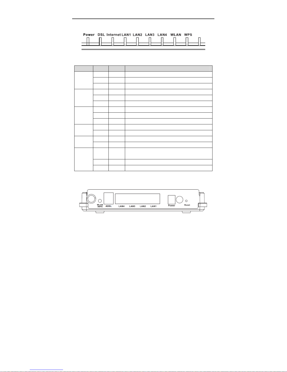
1.2 LEDs and Interfaces
1
Page 6
User Manual
Front Panel
The following table describes the LEDs of the device.
LEDs Color Status Description
Green On The initialization of the device is successful.
Power
DSL
INT
WiFi
LAN1~4
WPS
Green Off The device is powered off.
Red On POST Fail
Green On DSL link up / link synchronized.
Green Off Link disconnection.
Green Blinks Link training / DSL link not synchronized.
Green On Successful PPP session.
Red On Failure PPP session (1 minitue after link up).
Green Off Before DSL link up.
Green On The WLAN connection has been activated.
Green Off The WLAN connection is not activated.
Green On The LAN connection is nomal and activated.
Green Off The LAN interface is disconnected.
Green Blinks
Green Off WPS is idle.
Green On WPS negotiate succefully
WPS is triggered, and is waiting for client to
negotiate.
Rear Panel
2
Page 7

User Manual
The following table describes the interfaces and buttons of the device:
Interface Description
Reset to the factory default configuration. Keep the device
Reset
On/Off Power switch, power on or power off the device.
Power
LAN1~4
DSL
WLAN/WPS
powered on, and insert a needle into the hole for 3 seconds,
then release it. The deivce is reset to the factory default
configuration.
Power interface, for connecting to the power adapter of 12V
DC, 0.5A.
RJ-45 interface, for connecting to the Ethernet interface of a
PC or the Ethenet devices through an Ethernet cable.
RJ-11 interface, for connecting to the ADSL interface or a
splitter through a telephone cable.
Press the button between 1s and 6s to enable WLAN
function.
Press the button for more than 6s to enable WPS (Wi-Fi
Protected Setup) function.
1.3 System Requirements
Recommended system requirements are as follows:
Service subscriber
10 Base T/100 Base T Ethernet card
Hub or switch (attached to several PCs through one of Ethernet interfaces
on the device)
Operating system: Windows 98 SE, Windows 2000, Wndows ME, Windows
XP, Windows Vista, Window 7
Internet Explorer V5.0 or higher, Netscape V4.0 or higher, or FireFox 1.5 or
higher
1.4 Features
The device supports the following features:
Various line modes (line auto-negotiation)
3
Page 8

User Manual
External PPPoE dial-up access
Internal PPPoE/PPPoA dial-up access
1483B/1483R/MER access
Multiple PVCs (eight at most)
A single PVC with multiple sessions
Multiple PVCs with multiple sessions
Auto PVC
DHCP server
IPv4/IPv6
NAT/NAPT
ALG
TR-069
SNMP
Static route
Firmware upgrading through Web, TFTP, or FTP
Resetting to the factory defaults through Reset button or Web
DNS relay
Virtual server
Two-level passwords and usernames
Web interface
Telnet CLI
System status display
PPP session PAP/CHAP
IP/Port filter
Remote access control
Line connection status test
Remote management (Telnet; HTTP )
Backup and restoration of configuration file
IP quality of service (QoS)
Universal plug and play (UPnP)
WLAN with high-speed data transmission rate, compatible with IEEE
802.11b/g/n, 2.4 GHz compliant equipment
4
Page 9
User Manual
2 Hardware Installation
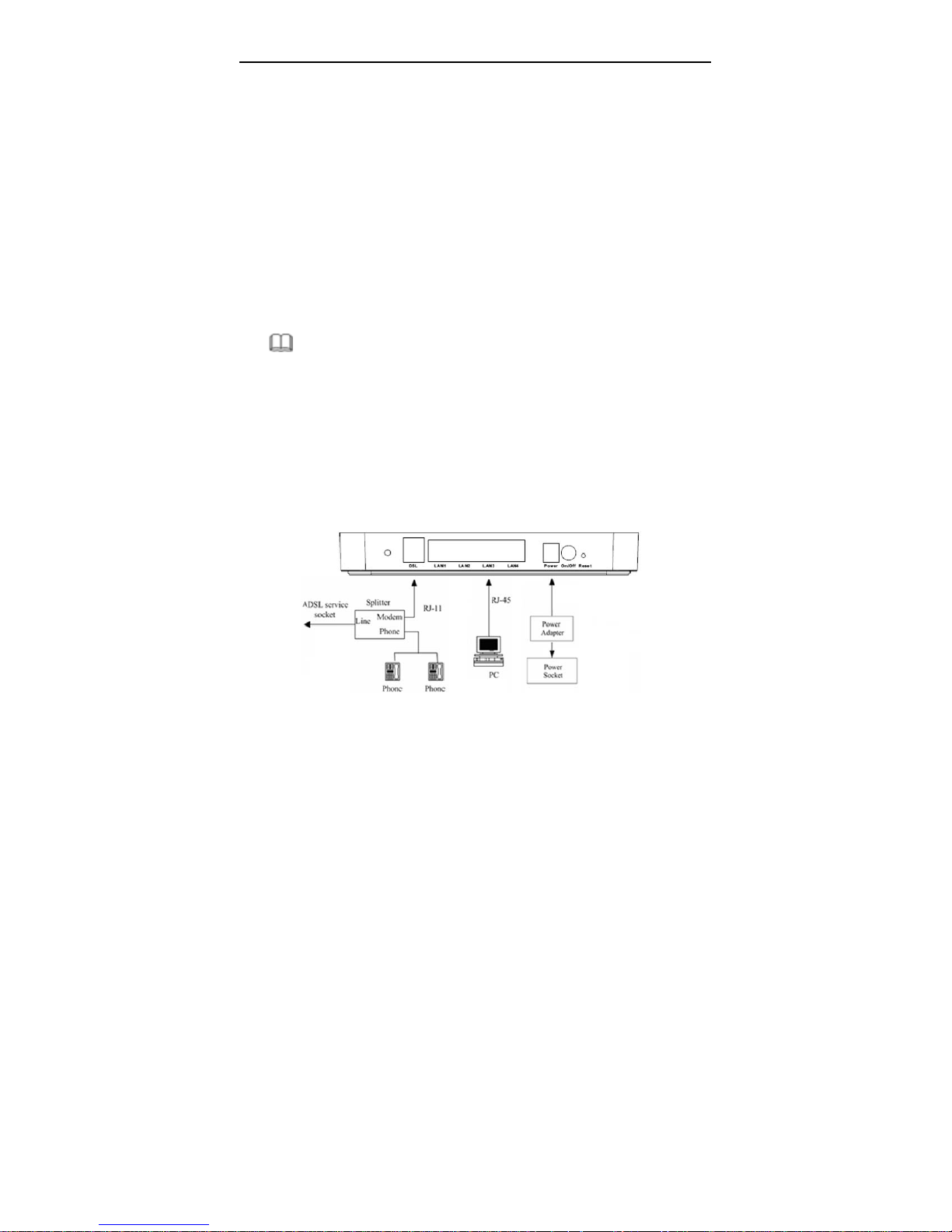
Step 1 Connect the DSL interface of the router and the Modem interface of
the splitter through a telephone cable. Connect the phone to the Phone
interface of the splitter through a cable. Connect the incoming line to the
Line interface of the splitter.
The splitter has three interfaces:
Line: Connect to a wall phone jack (RJ-11 jack)
Modem: Connect to the ADSL jack of the device
Phone: Connect to a telephone set.
Step 2 Connect the LAN interface of the modem with the network card of the
PC through an Ethernet line (MDI/MDIX).
Note:
Use twisted-pair cables to connect with the hub or Switch.
Step 3 Plug the power adapter to the wall outlet and then connect the other
end of it to the Power interface of the modem.
Connection 1
Figure1 displays the application diagram for the connection of the modem, PC,
splitter, and telephone sets, when no telephone set is placed before a splitter.
This type of connection is recommended.
Figure 1 Connection diagram (no telephone set is placed before the splitter)
5
Page 10
User Manual
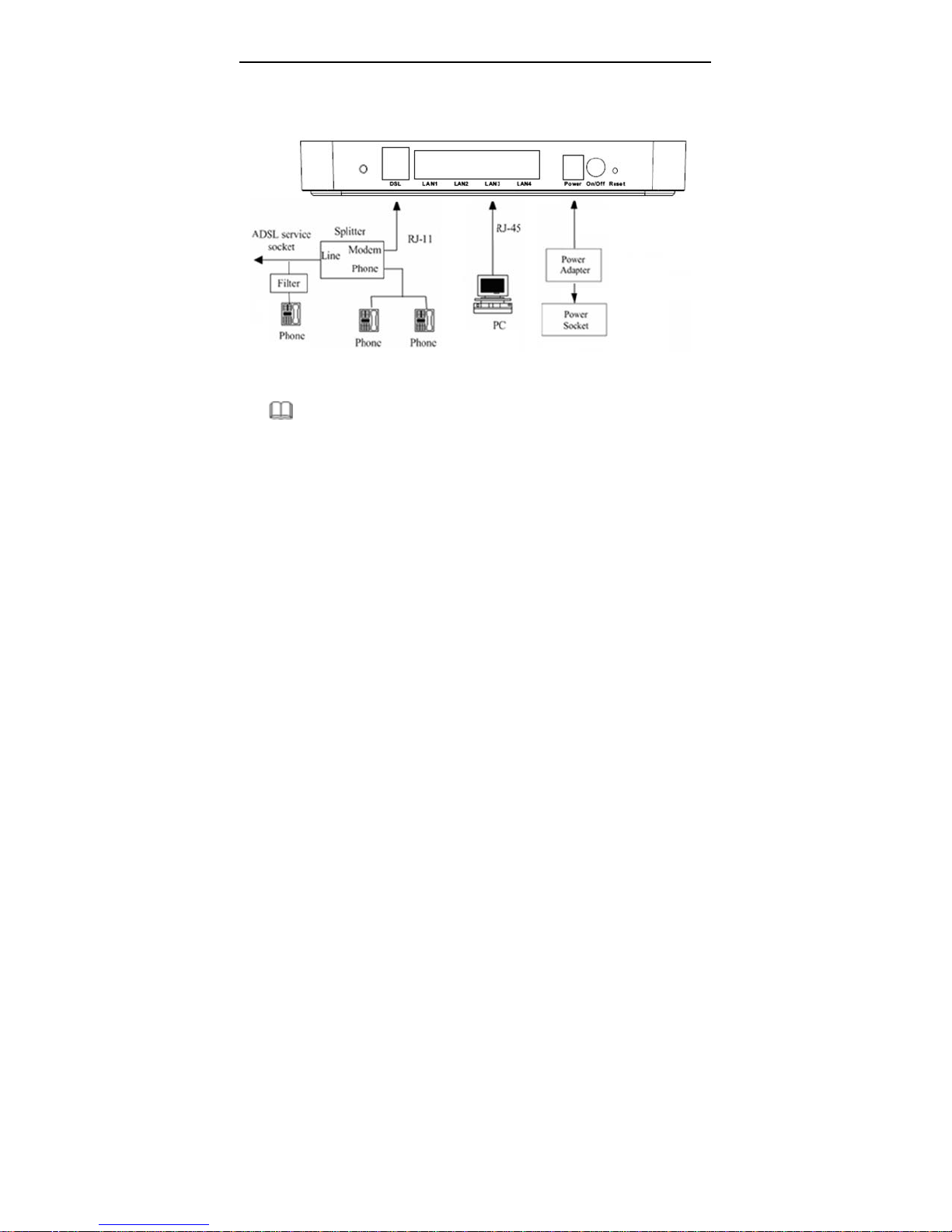
Connection 2
Figure 2 displays the connection when the telephone set is placed before a
splitter.
Figure 2 Connection diagram (a telephone set is plac ed be fo re the splitter)
Note:
In actual application, it is recommended to following connection 1. When
connection 2 is used, the filter must be installed close to the telephone cable.
See Figure2. Do not use the splitter to replace the filter.
Installing a telephone directly before the splitter may lead to a failure of
connection between the modem and the device of LAN side, or cannot access
into the Internet, or slow the connection speed. If you really need to add a
telephone set before the splitter, you have to add a microfilter before connecting
to a telephone set. Do not connect several telephones before the splitter. Do not
connect several telephones with the microfilter.
6
Page 11
User Manual
3 About the Web Configuration
This chapter describes how to configure the router by using the Web-based
configuration utility.
3.1 Access the Router
The following is the detailed description of accesing the router for the first time.
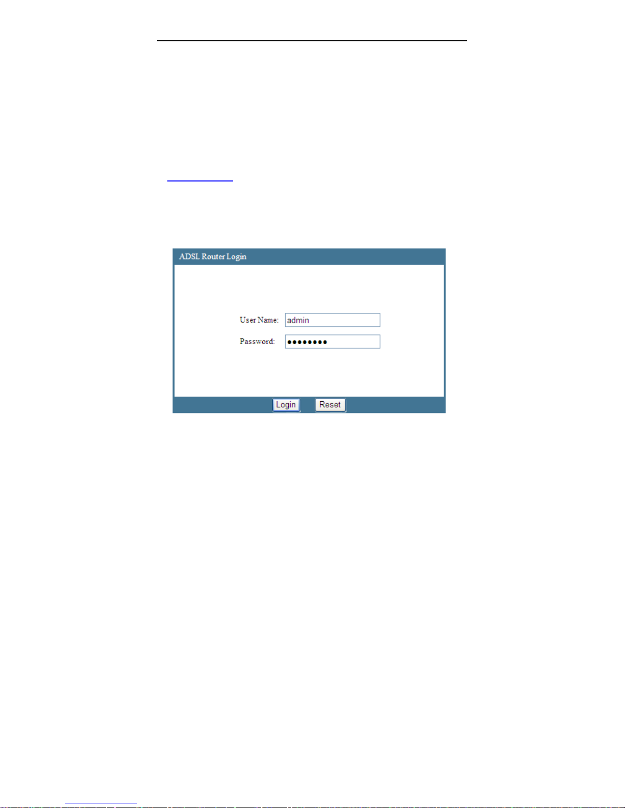
Configure the IP address of the PC as 192.168.1.X (2~254), netmask as 255.
255.255.0. Open the Internet Explorer (IE) browser and enter
http://192.168.1.1.In the Login page that is displayed, enter the username and
password.
The username and password of the super user are tmadmin and
tmadmin
The username and password of the common user are tmuser and
tmuser.
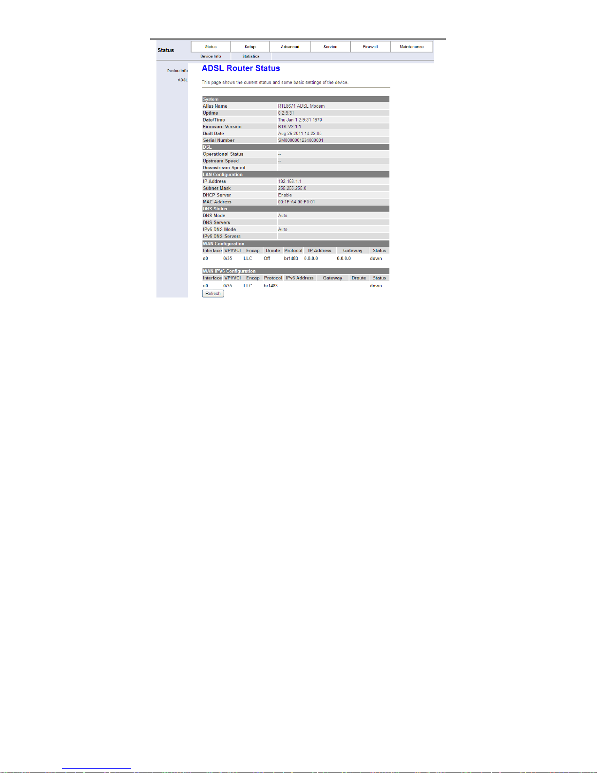
If you log in as a super user, you will see the Device Info page as shown below
appears. You can check the basic settings of the modem, such as firmware
version, upstream speed, downstream speed, LAN MAC address, LAN IP
address, DHCP server status. You can also view the basic status of WAN and
DNS server.
7
Page 12
User Manual
3.2 Status
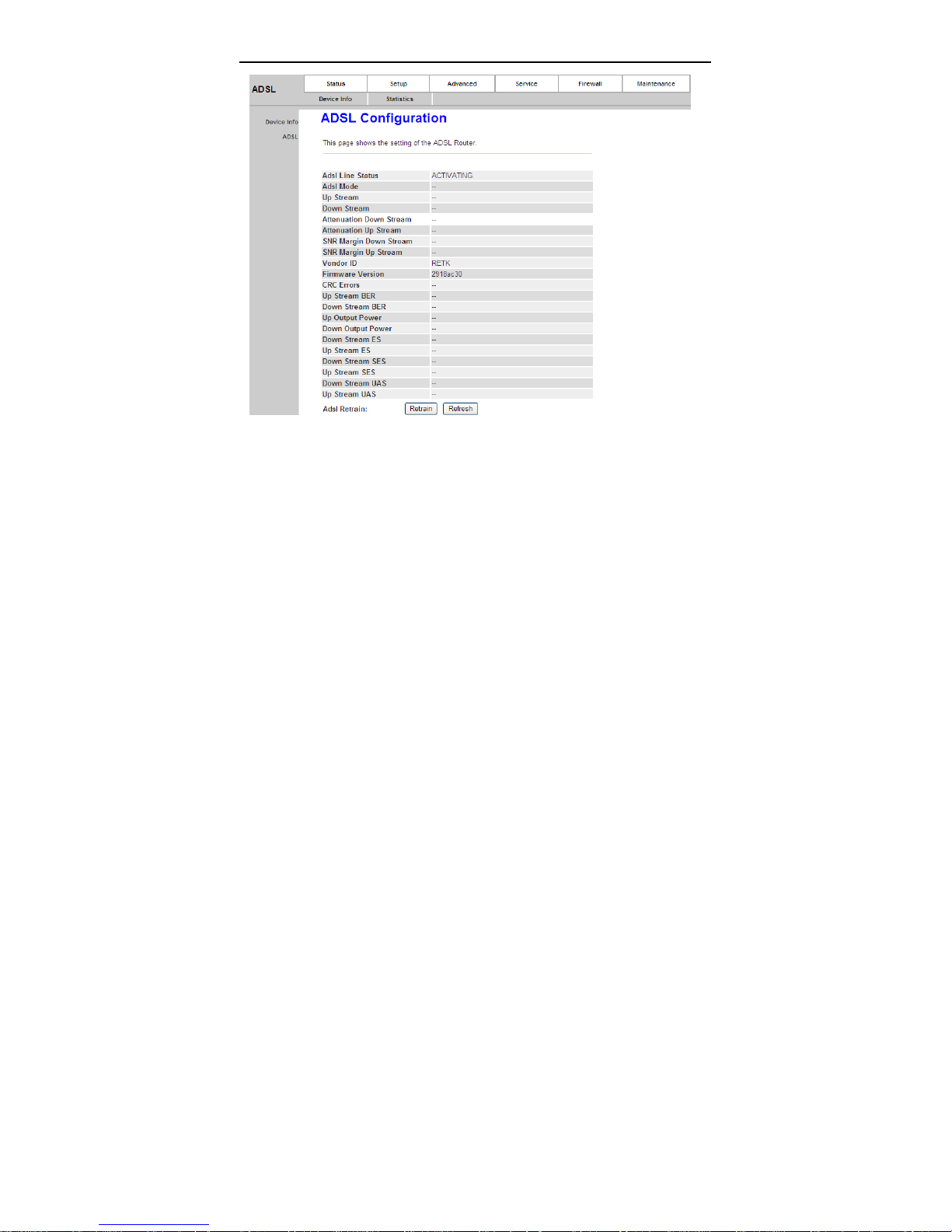
The tab Status contains Device Info and Statistics. Click Status > Device
Info > ADSL, the following page appears. You can see the router settings such
as the Adsl Line Status, Vendor ID and Firmware Version.
8
Page 13
User Manual
Click Status > Statistics, the following page appears. In this page, you can view
the statistics of each network port.
9
Page 14

User Manual
3.3 Quick Setup
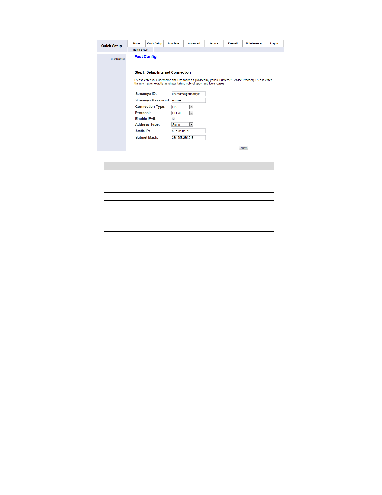
In the navigation bar, click Quick Setup. The tab Quick Setup contains a simple
way to setup WAN, and WLAN.
Quick Setup provided 3 simple steps to setup the connection. Below is an
example on each step.
10
Page 15
User Manual
3.3.1 Step 1
The following table describes the parameters of this page.
Field Description
Your Streamyx Username ID
Streamyx ID
Streamyx Password Your Streamyx Password
Connection Type You can choose LLC or VC-Mux.
Protocal You can choose PPPoE, PPPoA or Bridge
Enable IPv6
Address Type You can choose DHCP or Static
Static IP (Static Only) Your Streamyx Static IP
Subnet Mask Your Static Static IP Subnet Mask
After proper settings, click Next and the following page appears.
username@streamyx
username@tmnet
You can choose to enable IPv6.
(Only when you are inform by your ISP)
11
Page 16
User Manual
3.3.2 Step 2
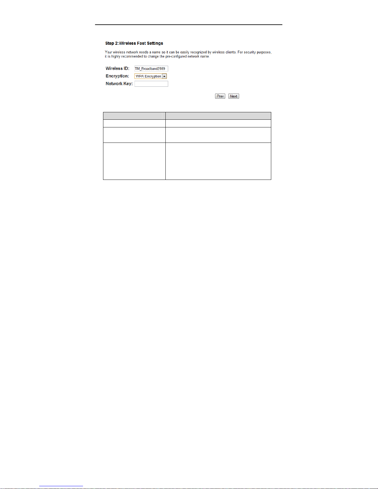
The following table describes the parameters of this page.
Field Description
Wireless ID Your Wireless SSID/Name
Encryption
Network Key
After proper settings, click Next and the following page appears.
You can choose WEP Encryption or WPA
Encryption
Your Wireless Security Key, your wireless
device should use the same key for
connection.
WEP : Must be 13 Characters
WPA : Range 8~63 Characters
12
Page 17
User Manual
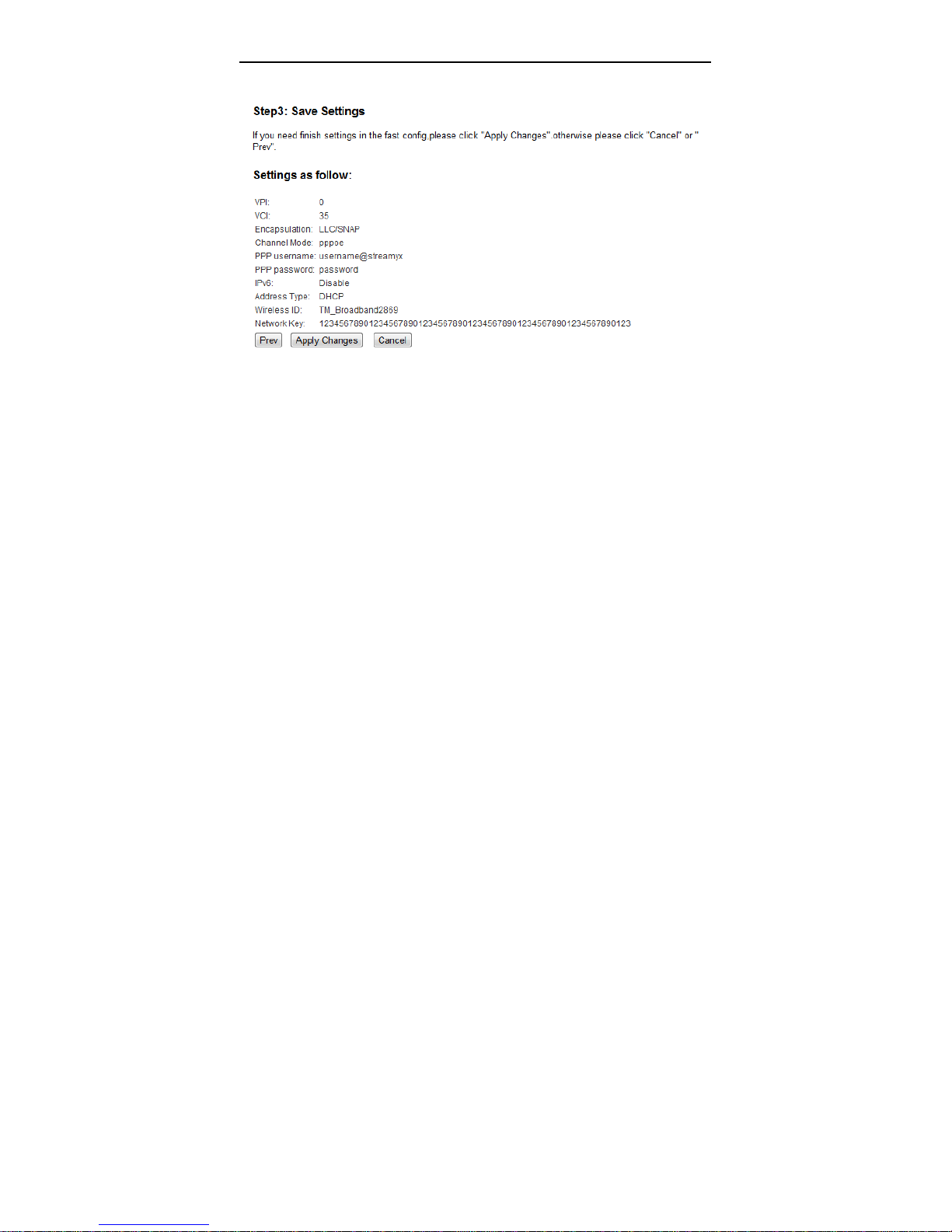
3.3.3 Step 3
You can check on the key-in info:
Click on Prev if you need to change any things.
Click on Apply changes to confirm the changes (The changes will be
applied immediately).
Click on Cancel to cancel the setup.
3.4 Setup
In the navigation bar, click Setup. The tab Setup contains WAN, LAN and
WLAN.
3.4.1 WAN Configuration
3.4.1.1 WAN
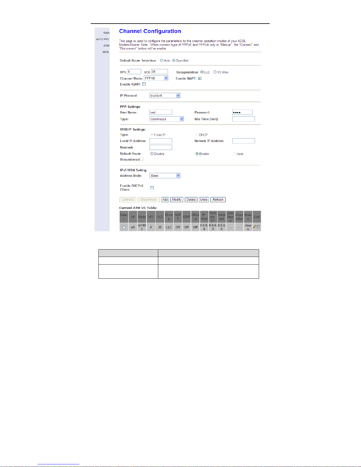
Choose Setup > WAN > WAN and the page shown in the following figure
appears.
In this page, you can configure WAN interface of your router.
13
Page 18
User Manual
The following table describes the parameters of this page.
Field Description
Default Route Selection You can select Auto or Specified.
VPI
The virtual path between two points in an
ATM network, ranging from 0 to 255.
14
Page 19

User Manual
Field Description
The virtual channel between two points in an
VCI
Encapsulation You can choose LLC and VC-Mux.
Channel Mode
Enable NAPT
Enabel IGMP
IP Protocol
PPP Settings
User Name
Password
Type
Idle Time (min)
WAN IP Settings
Type
ATM network, ranging from 32 to 65535 (1 to
31 are reserved for known protocols)
You can choose 1483 Bridged, 1483 MER,
PPPoE, PPPoA, 1483 Routed or IPoA.
Select it to enable Network Address Port
Translation (NAPT) function. If you do not
select it and you want to access the Internet
normally, you must add a route on the uplink
equipment. Otherwise, the access to the
Internet fails. Normally, it is enabled.
You can enable or disable Internet Group
Management Protocol (IGMP) function.
Select this interface support ipv4/ipv6, ipv4 or
ipv6.
Enter the correct user name for PPP dial-up,
which is provided by your ISP.
Enter the correct password for PPP dial-up,
which is provided by your ISP.
You can choose Continuous, Connect on
Demand or Manual.
If set the type to Connect on Demand, you
need to enter the idle timeout time. Within the
preset minutes, if the router does not detect
the flow of the user continuously, the router
automatically disconnects the PPPoE
connection.
You can choose Fixed IP or DHCP.
If select Fixed IP, you should enter the
local IP address, remote IP address and
subnet mask.
15
Page 20

User Manual
Field Description
If select DHCP, the router is a DHCP
client, the WAN IP address is assigned
by the remote DHCP server.
Local IP Address
Netmask
Unnumbered
IPv6 WAN Setting
Address Mode
Enable DHCPv6 Client
Add
Modify
Delete
Current ATM VC T able
After proper settings, click Add and the following page appears.
Enter the IP address of WAN interface
provided by your ISP.
Enter the subnet mask of the local IP
address.
Select this checkbox to enable IP
unnumbered function.
Set ipv6 wan setting if this interface support
ipv6
Select this interface support Slaac or Static to
generate wan ipv6 addresses.
Enable or disable dhcpv6 client on this
interface, if enable, user can specify if the
dhcpv6 client request Address or request
Prefix.
After configuring the parameters of this page,
click it to add a new PVC into the Current
ATM VC Table.
Select a PVC in the Current ATM VC Table,
then modify the parameters of this PVC. After
finishing, click it to apply the settings of this
PVC.
Select a PVC in the Current ATM VC Table,
and then click Delete to delete it
This table shows the existed PVCs. It shows
the interface name, channel mode, VPI/VCI,
encapsulation mode, local IP address,
remote IP address and other information. The
maximum item of this table is eight.
16
Page 21
User Manual
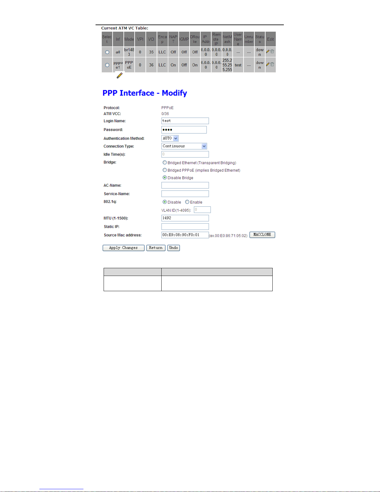
Click
this page, you can configure parameters of this PPPoE PVC.
in the PPPoE mode, the page shown in the following figure appears. In
The following table describes the parameters and buttons of this page.
Field Description
Protocol It displays the protocol type used for this WAN
connection.
17
Page 22

User Manual
Field Description
ATM VCC The ATM virtual circuit connection assigned for
this PPP interface (VPI/VCI).
Login Name The user name provided by your ISP.
Password The password provided by your ISP.
Authentication Method You can choose AUTO, PAP or CHAP.
Connection Type You can choose Continuous, Connect on
Demand or Manual.
Idle Time (s) If choose Connect on Demand, you need to
enter the idle timeout time. Within the preset
minutes, if the router does not detect the flow of
the user continuously, the router automatically
disconnects the PPPoE connection.
Bridge You can select Bridged Ethernet, Bridged
PPPoE or Disable Bridge.
AC-Name The accessed equipment type.
Service-Name The service name.
802.1q You can select Disable or Enable. After enable
it, you need to enter the VLAN ID. The value
ranges from 1 to 4095.
Apply Changes Click it to save the settings of this page
temporarily.
Return Click it to return to the Channel Configuration
page.
Reset Click it to refresh this page.
Source Mac address The MAC address you want to clone.
MAC Clone Click it to enable the MAC Clone function with
the MAC address that is configured.
3.4.1.2 Automatically PVC
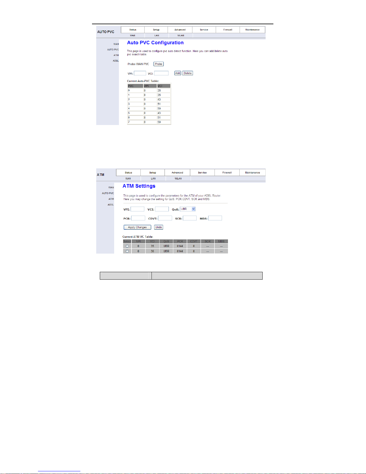
Click Auto PVC in the left pane, page shown in the following figure appears. In
this page, you can get PVC automatically through detecting function, and add or
delete the PVC that you do not want.
18
Page 23
User Manual
3.4.1.3 ATM Setting
Click AT M Setti ng in the left pane, the page shown in the following figure
appears. In this page, you can configure the parameters of the ATM, including
QoS, PCR, CDVT, SCR and MBS.
The following table describes the parameters of this page.
Field Description
19
Page 24

User Manual
Field Description
VPI The virtual path identifier of the ATM PVC.
VCI The virtual channel identifier of the ATM PVC.
QoS The QoS category of the PVC. You can choose
UBR, CBR, rt-VBR or nrt-VBR.
PCR Peak cell rate (PCR) is the maximum rate at
which cells can be transmitted along a connection
in the ATM network. Its value ranges from 1 to
65535.
CDVT Cell delay variation tolerance (CDVT) is the
amount of delay permitted between ATM cells (in
microseconds). Its value ranges from 0 to
4294967295.
SCR Subtain cell rate (SCR) is the maximum rate tha t
traffic can pass over a PVC without the risk of cell
loss. Its value ranges from 0 to 65535.
MBS Maximum burst size (MBS) is the maximum
number of cells that can be transmitted at the
PCR. Its value ranges from 0 to 65535.
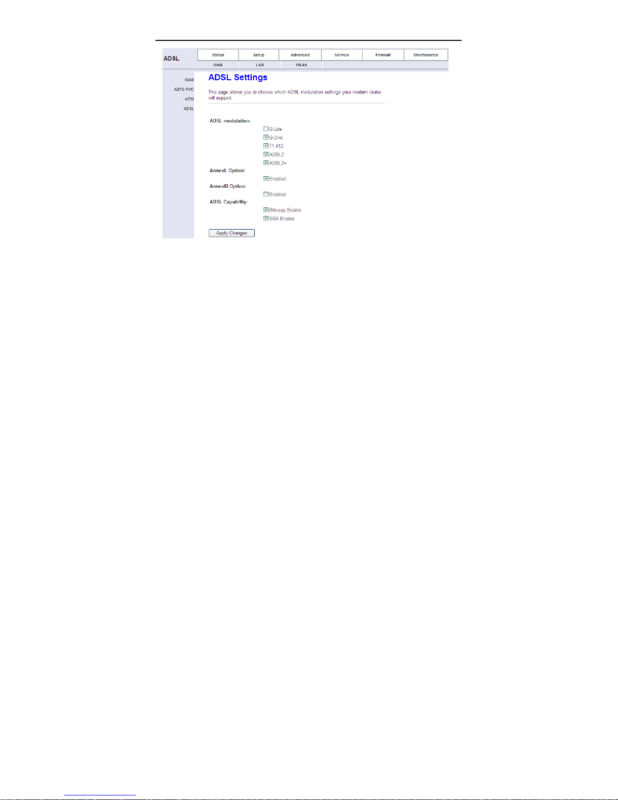
3.4.1.4 ADSL Setting
Click ADSL Setting in the left pane, the page shown in the following figure
appears. In this page, you can select the DSL modulation. Generally you need to
remain this factory default settings. The router negotiates the modulation modes
with the DSLAM.
20
Page 25
User Manual
3.4.2 LAN
3.4.2.1 LAN
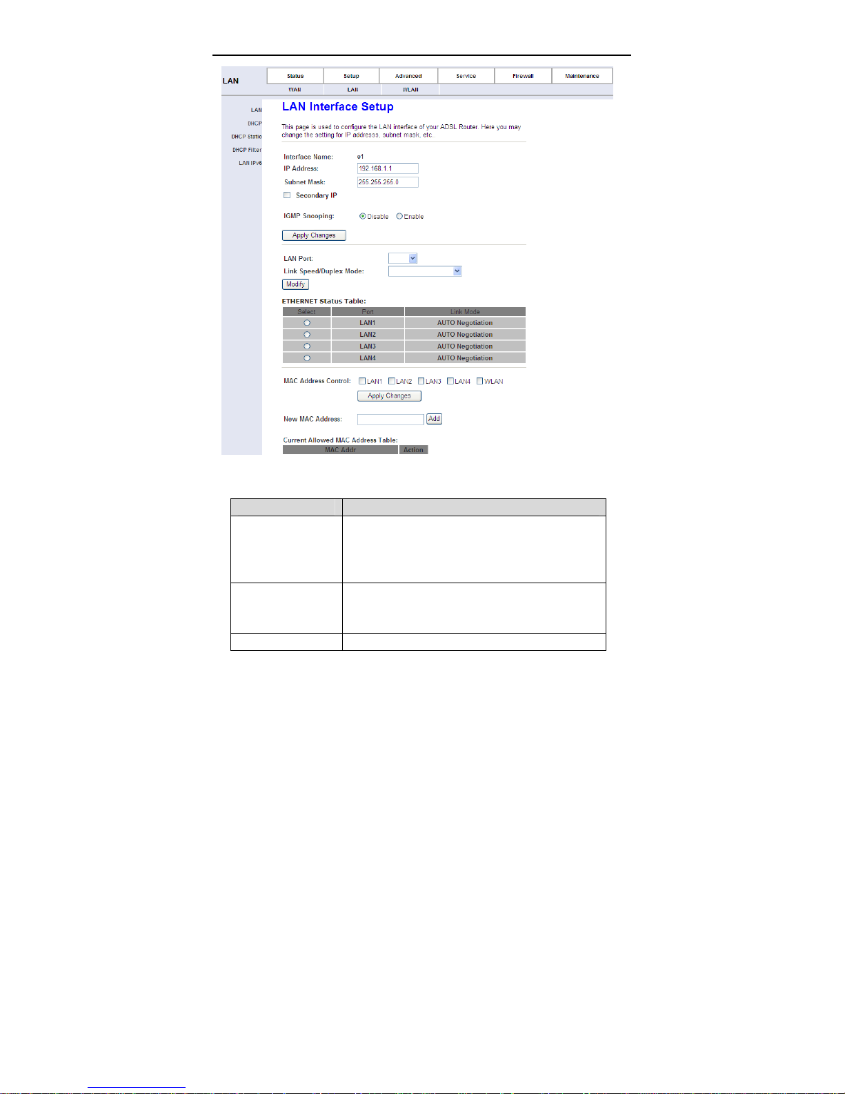
Click LAN in the left pane, the page shown in the following figure appears.
In this page, you can change IP address of the router. The default IP address is
192.168.1.1, which is the private IP address of the router.
21
Page 26
User Manual
The following table describes the parameters of this page.
Field Description
Enter the IP address of LAN interface. It is
IP Address
Subnet Mask
Secondary IP Select it to enable the secondary LAN IP address.
recommended to use an address from a block that
is reserved for private use. This address block is
192.168.1.1- 192.168.255.254.
Enter the subnet mask of LAN interface. The range
of subnet mask is from
255.255.0.0-255.255.255.254.
22
Page 27

User Manual
Field Description
The two LAN IP addresses must be in the different
network.
LAN Port
Link Speed/Duplex
Mode
Modify
Ethernet Status
Table
MAC Address
Control
New MAC Address A MAC address to be added.
Current Allowed
MAC Address
Table
You can choose the LAN interface you want to
configure.
You can select the following modes from the
drop-downlist:100Mbps/FullDuplex,100Mbps/Half
Duplex,10Mbps/FullDuplex,10Mbps/Half Duplex
and Auto Negotiation.
Select the index from Ethernet status table, and
then click modify.
It shows the current Ethernet status list.
Select the LAN interface on which you want to run
MAC Address Control.
It shows the current allowed MAC address list.
3.4.2.2 DHCP
Click DHCP in the left pane, the page shown in the following figure appears.
23
Page 28

User Manual
The following table describes the parameters of this page.
Field Description
If set to DHCP Server, the router can assign IP
DHCP Mode
IP Pool Range
Pool Size It allows the size machines that can be set up
Show Client
Default Gateway Enter the default gateway of the IP address pool.
Max Lease Time
addresses, IP default gateway and DNS Servers to
the host in Windows95, Windows NT and other
operation systems that support the DHCP client.
It specifies the first IP address in the IP address pool.
The router assigns IP address that base on the IP
pool range to the host.
Click it, the Active DHCP Client Table appears. It
shows IP addresses assigned to clients.
The lease time determines the period that the host
retains the assigned IP addresses before the IP
24
Page 29
User Manual
Field Description
addresses change.
Enter the domain name if you know. If you leave this
blank, the domain name obtained by DHCP from the
Domain Name
DNS Servers
Set VendorClass
IP Range
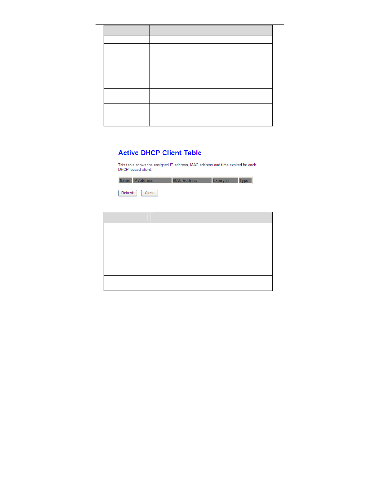
Click Show Client in the DHCP Mode page, the page shown in the following
figure appears. You can view the IP address assigned to each DHCP client.
The following table describes the parameters and buttons in this page.
Field
IP Address
MAC Address
Expiry (s)
ISP is used. You must enter host name (system
name) on each individual PC. The domain name can
be assigned from the router through the DHCP
server.
You can configure the DNS server ip addresses for
DNS Relay.
Click it, the Device IP Range Table page appears.
You can configure the IP address range based on the
device type.
Description
It displays the IP address assigned to the DHCP
client from the router.
It displays the MAC address of the DHCP client.
Each Ethernet device has a unique MAC address.
The MAC address is assigned at the factory and it
consists of six pairs of hexadecimal character, for
example, 00-A0-C5-00-02-12.
It displays the lease time. The lease time determines
the period that the host retains the assigned IP
25
Page 30
User Manual
Field
Refresh Click it to refresh this page.
Close Click it to close this page.
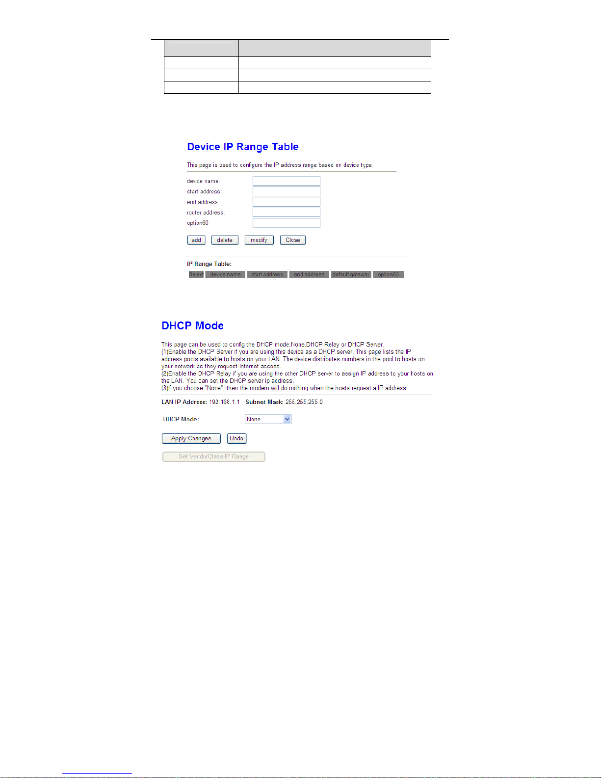
Click Set VendorClass IP Range in the DHCP Mode page, the page as shown in
the following figure appears. In this page, you can configure the IP address range
based on the device type.
Choose None in the DHCP Mode field, and the page shown in the following
figure appears.
Description
addresses before the IP addresses change.
26
Page 31
User Manual
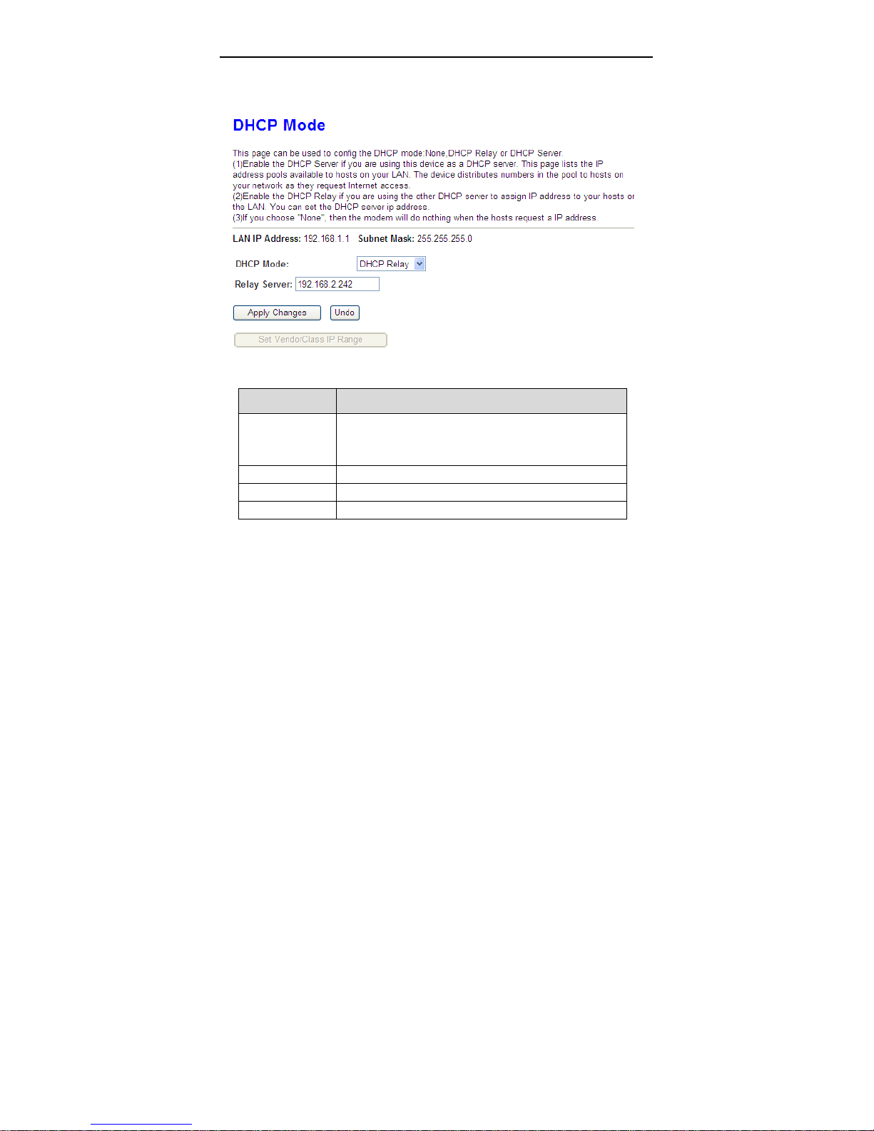
In the DHCP Mode field, choose DHCP Relay. The page shown in the following
figure appears.
The following table describes the parameters and buttons of this page.
Field Description
If set to DHCP Relay, the router acts a surrogate
DHCP Mode
Relay Server Enter the DHCP server address provided by your ISP.
Apply Changes Click it to save the settings of this page.
Undo Click it to refresh this page.
DHCP Server and relays the DHCP requests and
reponses between the remote server and the client.
3.4.2.3 DHCP Static
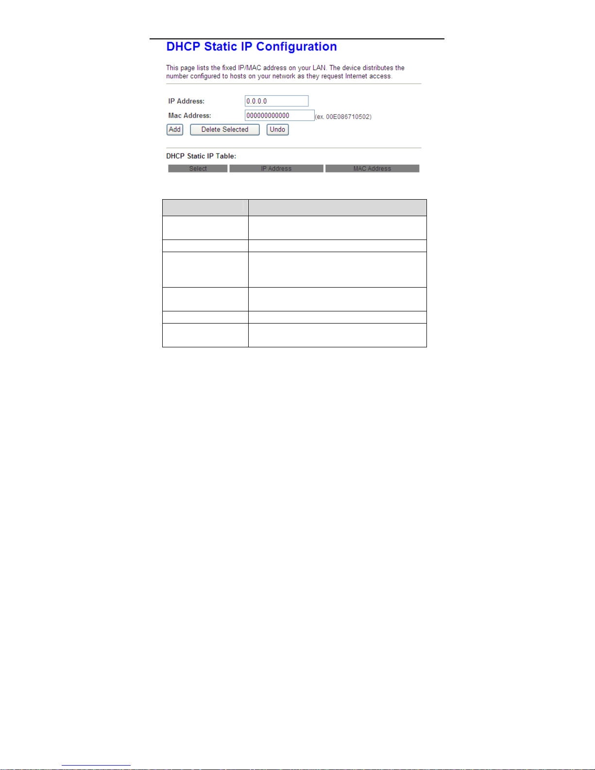
Click DHCP Static in the left pane, the page shown in the following figure
appears. You can assign the IP addresses on the LAN to the specific individual
PCs based on their MAC address.
27
Page 32
User Manual
The following table describes the parameters and buttons of this page.
Field Description
IP Address Enter the specified IP address in the IP pool
range, which is assigned to the host.
MAC Address Enter the MAC address of a host on the LAN.
Add After entering the IP address and MAC address,
click it. A row will be added in the DHCP Static IP
Table.
Delete Selected Select a row in the DHCP Static IP Table, then
click it, this row is deleted.
Undo Click it to refresh this page.
DHCP Static IP Table It shows the assigned IP address based on the
MAC address.
3.4.2.4 DHCP Filter
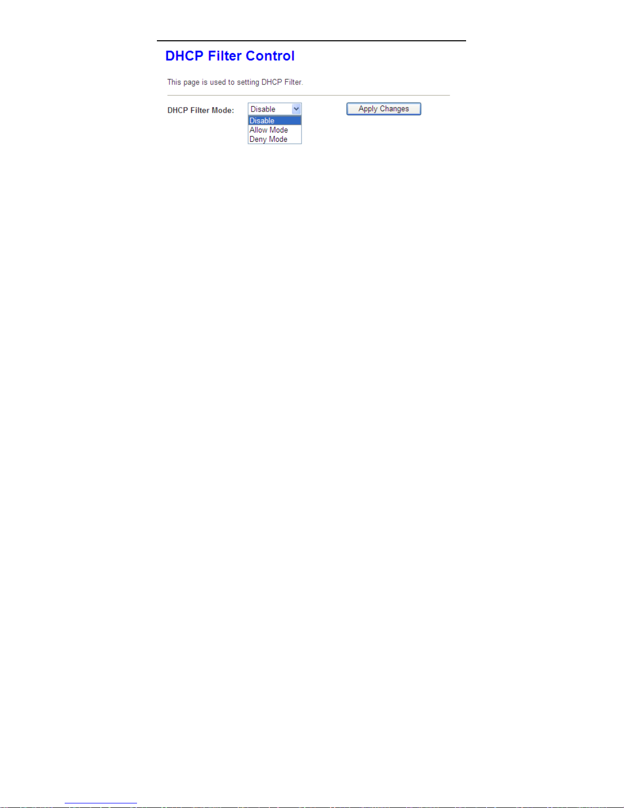
Click DHCP Filter in the left pane, the page shown in the following figure
appears.
28
Page 33
User Manual
3.4.2.5 LAN IPv6
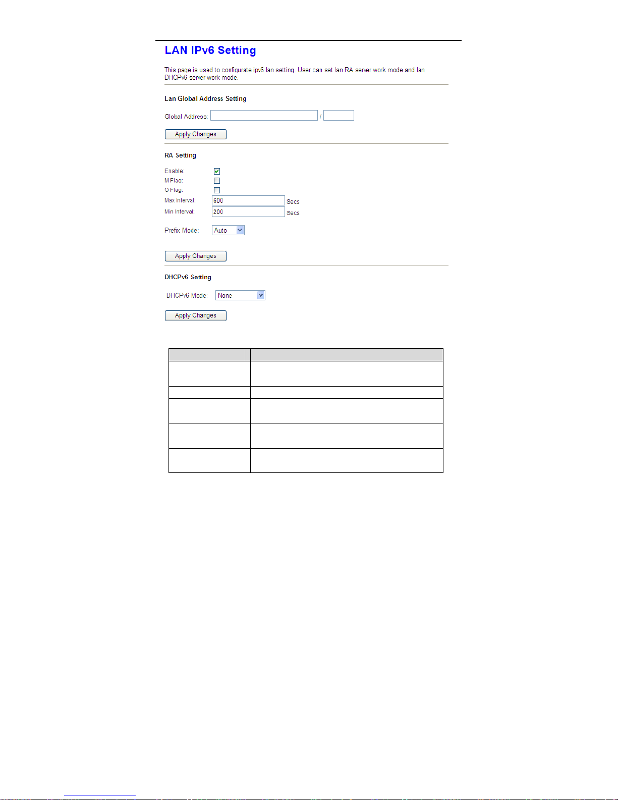
Click LAN IPv6 in the left pane, the page shown in the following figure appears.
In this page, you can change IP address of the router. The default IP address is
192.168.1.1, which is the private IP address of the router.
29
Page 34
User Manual
The following table describes the RA parameters of this page.
Field Description
Global Address
Enable Enable or disable the Router Advertisement feature
M Flag
O Flag
Prefix Mode
Specify the lan global ipv6 address, may be
assigned by ISP
Enable or disable the “Managed address
configuration” flag in RA packet
Enable or disable the “Other configuration” flag in
RA packet
Specify the RA feature prefix mode:
“Auto”: the RA prefix will use Wan dhcp-pd prefix;
30
Page 35
User Manual
Field Description
“Manual”: user will specify the prefix Address,
Length, Preferred time and Valid time.
Sepecify the dhcpv6 server mode:
“None”: close dhcpv6 server.
“Manual”: dhcpv6 server is opened and user
DHCPv6 Mode
specify the dhcpv6 server address pool and other
parameters.
“Auto”: dhcpv6 server is opened and it use Wan
dhcp-pd prefix to generate address pool.
3.4.3 WLAN
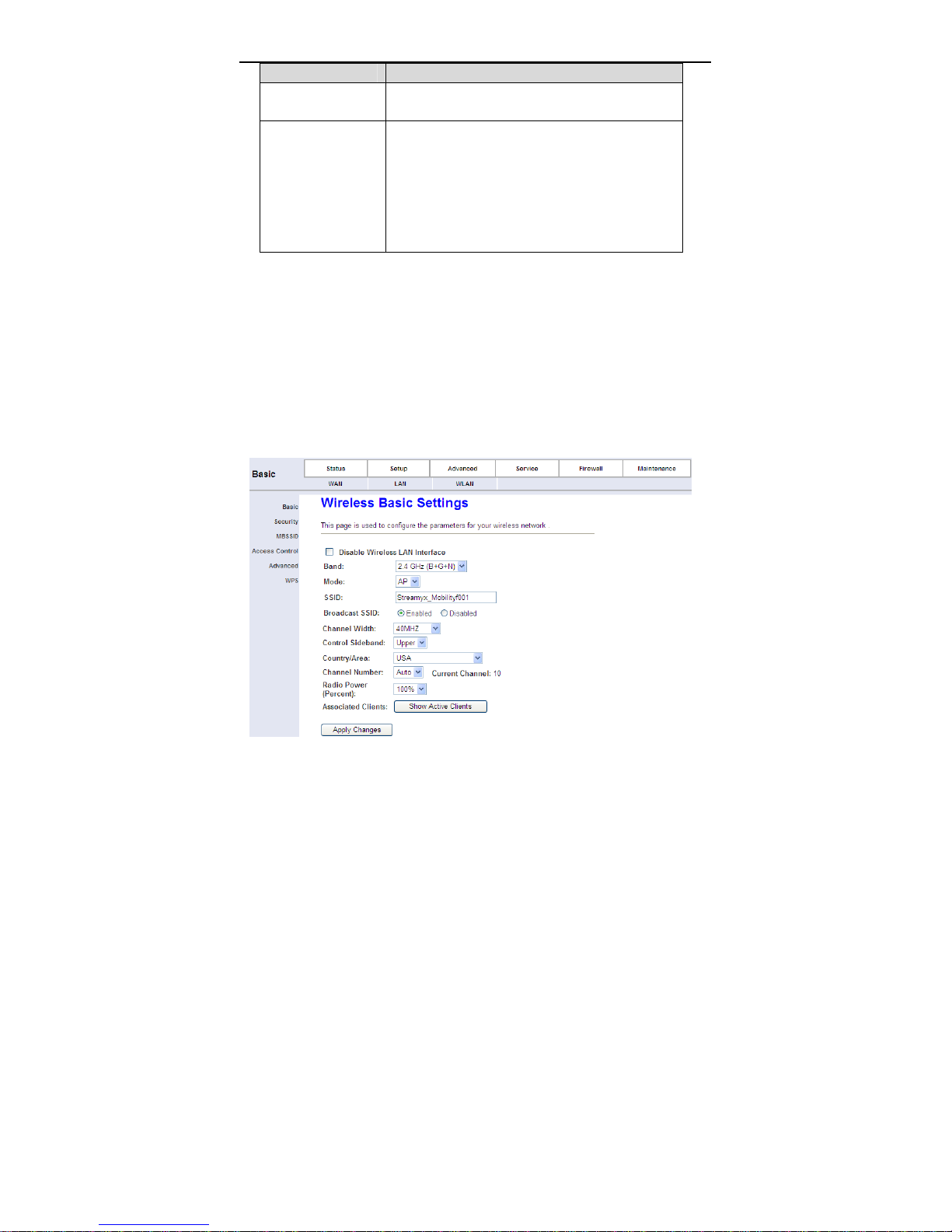
Choose Setup > WLAN. The WLAN page that is displayed contains Basic,
Security, MBSSID, Access Control, Advanced and WPS.
3.4.3.1 Basic Settings
Choose WL AN > Basic, and the following page appears. In this page, you can
configure the parameters for wireless LAN clients that may connect to the
modem.
31
Page 36
User Manual
The following table describes the parameters of this page.
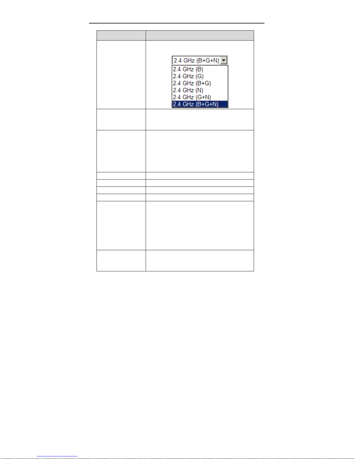
Field Description
Choose the working mode of the modem. You can
choose from drop-down list.
Band
Choose the network model of the modem, which
Mode
SSID
Broadcast SSID Enable or disable this function.
Channel Width You can choose 20MHZ, 40MHZ or 20/40MHZ.
Control Sideband You can choose Upper or Lower.
Country/Area Select the country from the drop-down list.
Channel Number
Radio Power
is varied according to the software. By default, the
network model of the modem is AP.
The service set identification (SSID) is a unique
name to identify the modem in the wireless LAN.
Wireless stations associating to the modem must
have the same SSID. Enter a descriptive name
that is used when the wireless client connecting to
the modem.
A channel is the radio frequency used by
802.11b/g/n wireless devices. You should use a
different channel from an adjacent AP to reduce
the interference. Interference and degrading
performance occurs when radio signal from
different APs overlap. Choose a channel from the
drop-down list box.
You can choose the transmission power of the
radio signal. The default one is 100%. It is
recommended to choose the default value100%.
32
Page 37
User Manual
Field Description
Show Active Clients
Apply Changes
Click it to view the information of the wireless
clients that are connected to the modem.
Click it to apply the settings temporarily. If you
want to save the settings of this page
permanently, click Save in the lower left corner.
3.4.3.2 Security
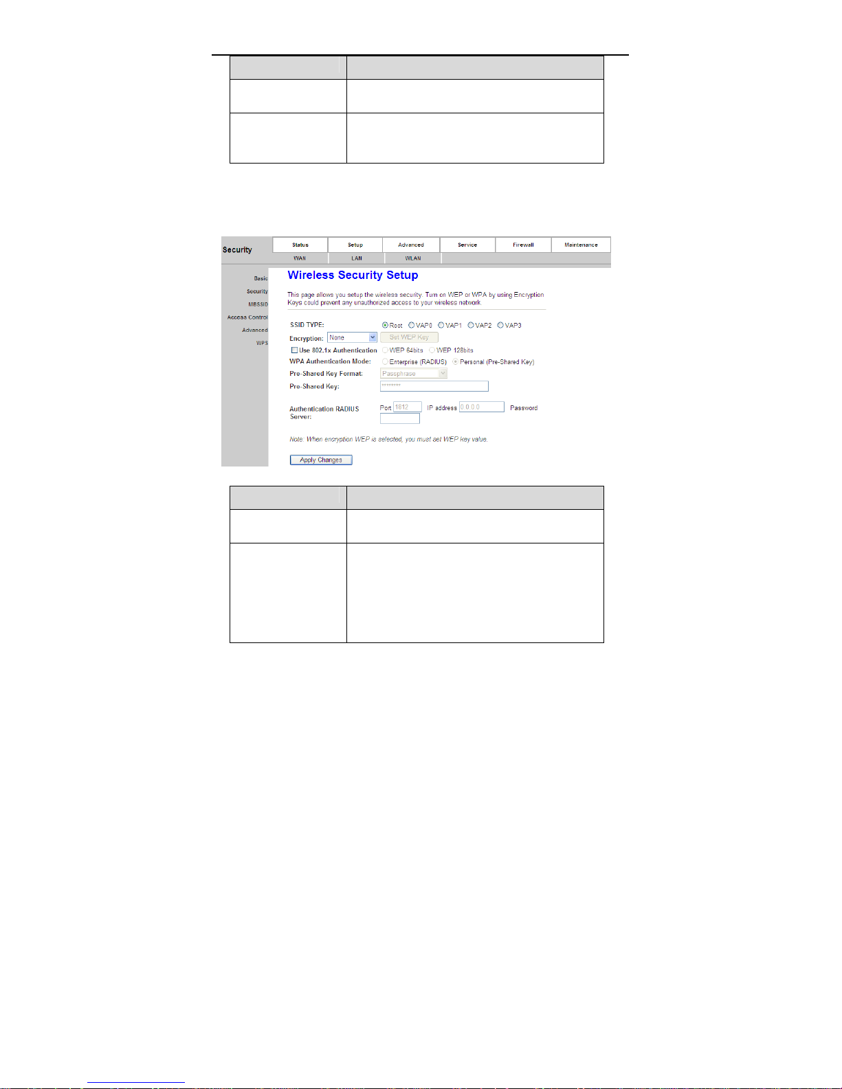
Choose WLAN > Security, and the following page appears.
The following table describes the parameters of this page.
Field Description
SSID Type
Encryption
Service Set Identifier, is a name of a local area
network
Configure the wireless encryption mode. You can
choose None, WEP, WPA (TKIP), WPA (AES),
WPA2 (AES), WPA2 (TKIP) or WPA2 Mixed.
Wired equivalent privacy0 (WEP) encrypts
data frames before transmitting over the
wireless network.
33
Page 38

User Manual
Field Description
Wi-Fi protected access (WPA) is a subset of
the IEEE802.11i security specification draft.
WPA2 Mixed is the collection of WPA and
WPA2 encryption modes. The wireless client
establishes the connection between the
modem through WPA or WPA2.
Key differences between WPA and WEP are user
authentication and improved data encryption.
It is available when you set the encryption mode
Set WEP Key
WPA Authentication
Mode
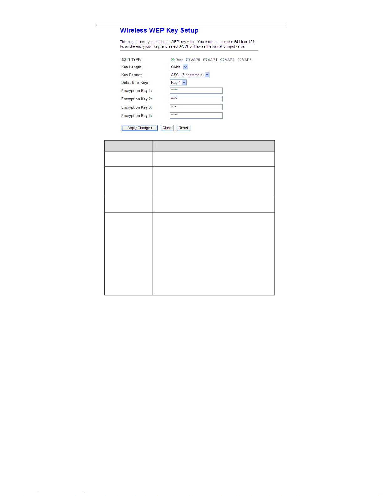
Click Set WEP Key, and the following page appears.
to WEP. Click it, the Wireless WEP Key Setup
page appears.
Select Personal (Pre-Shared Key), enter the
pre-shared key in the Pre-Shared Key field.
Select Enterprise (RADIUS), enter the port,
IP address, and password of the Radius
server. You need to enter the username and
password provided by the Radius server
when the wireless client connects the
modem.
If the encrypton is set to WEP, the modem uses
802.1 X authentication, which is Radius
authentication.
34
Page 39
User Manual
The following describes the parameters of this page.
Field Description
Key Length
Key Format
Default Tx Key
Encryption Key 1
to 4
Choose the WEP key length. You can Choose
64-bit or 128-bit.
If you choose 64-bit, you can choose ASCII (5
characters) or Hex (10 characters).
If you choose 128-bit, you can choose ASCII
(13 characters) or Hex (26 characters).
Choose the index of WEP Key . You can choose Key
1, Key 2, Key 3 or Key 4.
The Encryption keys are used to encrypt the data.
Both the modem and wireless stations must use the
same encryption key for data transmission.
If you choose 64-bit and ASCII (5 characters),
enter any 5 ASCII characters.
If you choose 64-bit and Hex (10 characters),
enter any 10 hexadecimal characters.
If you choose 128-bit and ASCII (13
characters), enter any 13 ASCII characters.
If you choose 128-bit and Hex (26 characters),
enter any 26 hexadecimal characters.
35
Page 40

User Manual
Field Description
Click it to apply the settings temporarily. If you want
Apply Changes
to save the settings of this page permanently, click
Save in the lower left corner.
3.4.3.3 Multi-BSSID
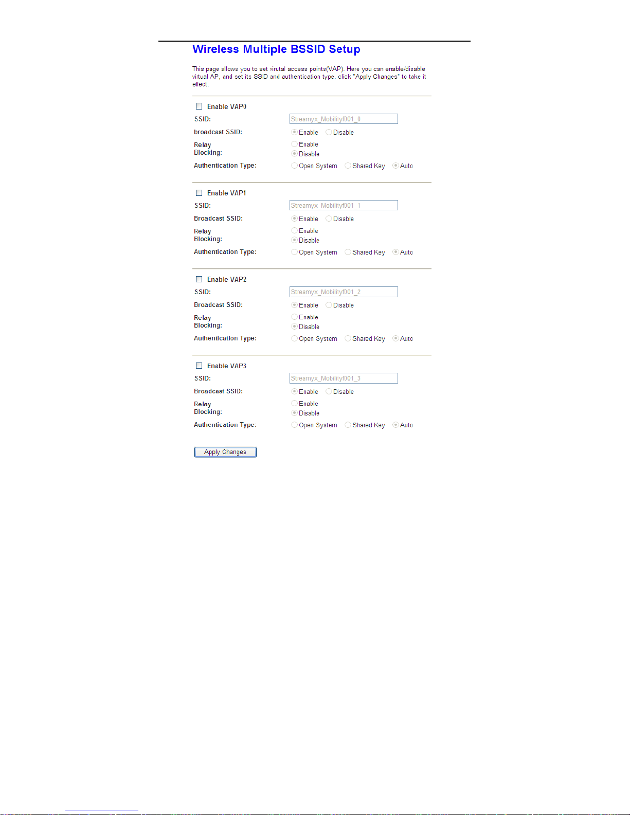
Choose WLAN > MBSSID, and the following page appears. In this page, you can
configure the multi-BSSID of the wireless clients.
36
Page 41
User Manual
37
Page 42
User Manual
It supports 4 virutal access points (VAPs).It is a unique name to identify the
modem in the wireless LAN. Wireless stations associating to the modem must
have the same name. Enter a descriptive name that is used when the wireless
client connecting to the modem.
3.4.3.4 Access Control
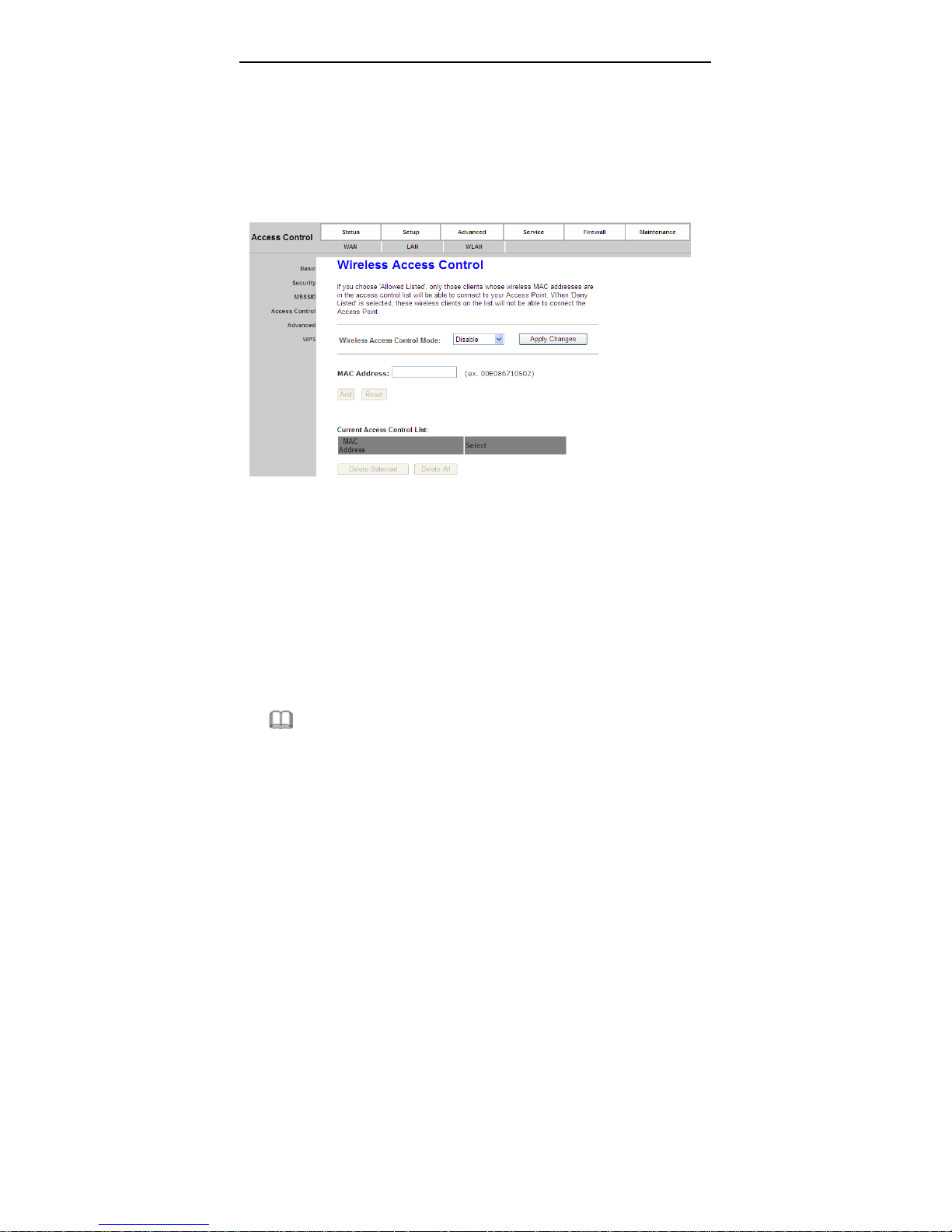
Choose WLAN > Access Control, and the following page appears. In this page,
you can configure the access control of the wireless clients.
Choose Allow Listed as the access control mode to enable white list function.
Only the devices whose MAC addresses are listed in the Current Access
Control List can access the modem.
Choose Deny Listed as the access control mode to to enable black list function.
The devices whose MAC addresses are listed in the Current Access Control
List are denied to access the modem.
3.4.3.5 Advanced
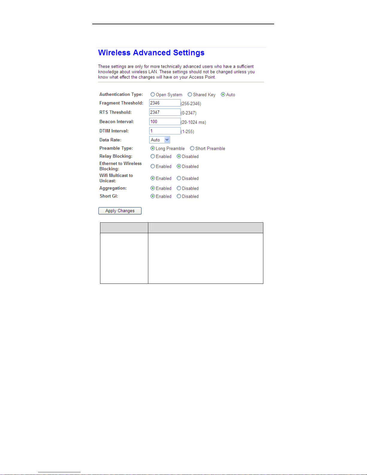
Choose Wireless > Advanced, and the following page appears. In this page,
you can configure the wireless advanced parameters. It is recommended to use
the default parameters.
Note:
38
Page 43
User Manual
The parameters in the Advanced are modified by the professional personnel,
it is recommended to keep the default values.
The following table describes the parameters of this page.
Field Description
Select the modem operating in the open system or
encryption authentication. You can choose Open
System, Shared Key or Auto.
Authentication
In the open system, the wireless client can
directly connect to the device
In the encryption authentication, the wireless
client connects to the modem through the
39
Page 44

Field Description
Data Rate
PreambleType
Broadcast SSID
Relay Blocking
Ethernet to
Wireless Blocking
Wifi Multicast to
Unicast
Aggregation
Short GI
Apply Changes
User Manual
shared key.
Choose the transmission rate of the wireless data.
You can choose Auto, 1 M, 2 M, 5.5 M, 11 M, 6 M,
9 M, 12 M, 18 M, 24 M, 36 M, 48 M, 54M, MSC0 ~
MSC7.
Long Preamble: It means this card always
use long preamble.
Short Preamble: It means this card can
support short preamble capability.
Select whether the modem broadcasts SSID or not.
You can select Enable or Disable.
Select Enable, the wireless client searches the
modem through broadcasting SSID.
Select Disable to hide SSID, the wireless
clients can not find the SSID.
Wireless isolation. Select Enable, the wireless
clients that are connected to the modem can not
intercommunication.
Whether the wireless network can communicate
with the Ethernet network or not.
Enable it to using unicast to transmit multicast
packet
It is applied when the destination end of all MPDU
are for one STA.
It is not recommended to enable GI in obvious
environment of Multi-path effect.
Click it to apply the settings temporarily. If you want
to save the settings of this page permanently, click
Save in the lower left corner.
3.4.3.6 WPS
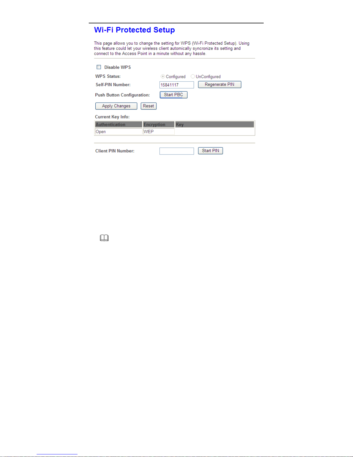
Choose WLAN > WPS and the following page appears.
40
Page 45
User Manual
There are two ways for the wireless client to establish the connection with the
modem through WPS. The modem generates PIN, see the above figure. Click
Regenerate PIN to generate a new PIN, and then click Start PBC, In the
wireless client tool, enter the PIN which is generated by the modem, start
connection. The client will automatically establish the connection with the modem
through the encryption mode, and you need not to enter the key. The other way is
the wireless client generates PIN. In the above figure, enter PIN of the wireless
client in the Client PIN Number field, then click Start PIN to establish the
connection.
Note:
The wireless client establishes the connection with the modem through WPS
negotiation.The wireless client must support WPS
3.5 Advanced
41
Page 46
User Manual
In the navigation bar, click Advanced. The tab Advanced contains Route, NAT,
QoS, CWMP, Port Mapping and Others.
3.5.1 Route
Choose Advanced > Route, the page shown in the following figure appears. The
page that is displayed contains Static Route, IPv6 Static Route and RIP.
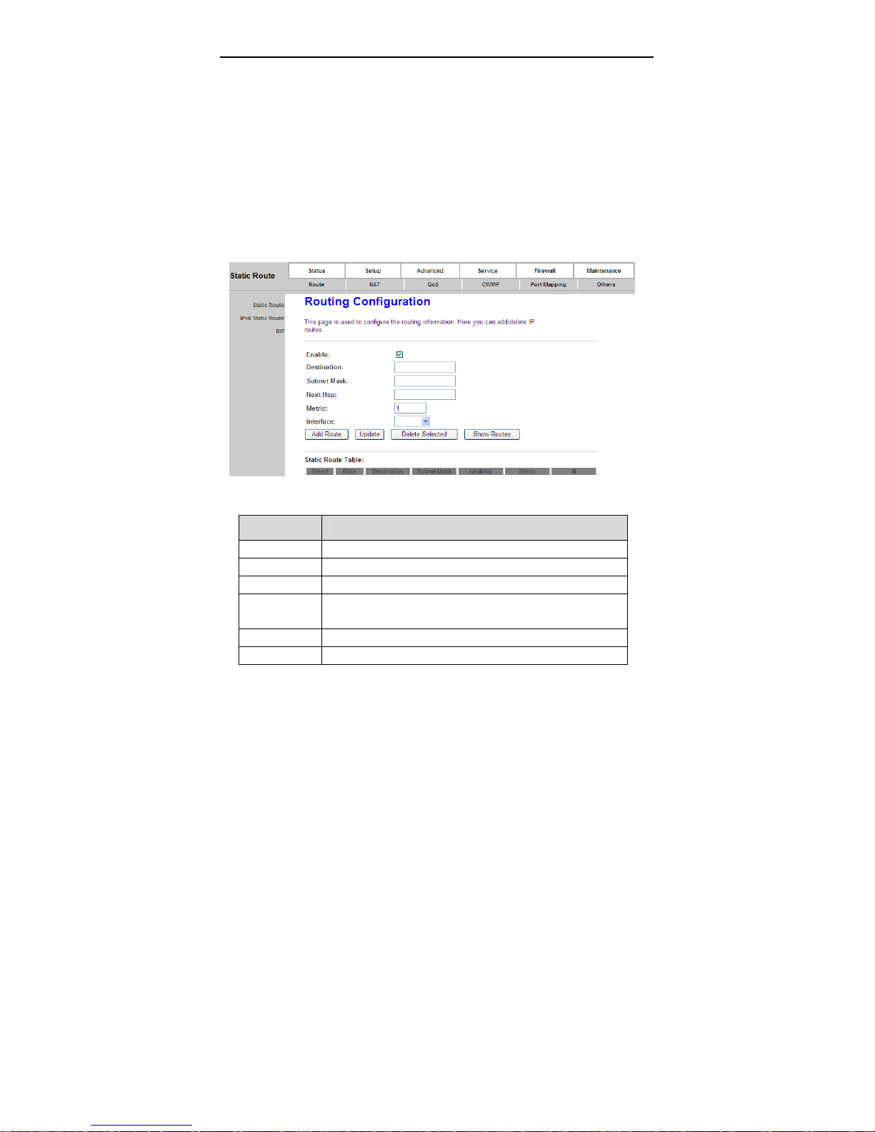
3.5.1.1 Static Route
Click Static Route in the left pane, the page shown in the following figure
appears. This page is used to configure the routing information. You can add or
delete IP routes.
The following table describes the parameters and buttons of this page.
Field Description
Enable Select it to use static IP routes.
Destination Enter the IP address of the destination device.
Subnet Mask Enter the subnet mask of the destination device.
Next Hop Enter the IP address of the next hop in the IP route to the
destination device.
Metric The metric cost for the destination.
Interface The interface for the specified route.
42
Page 47
User Manual
Field Description
Add Route Click it to add the new static route to the Static Route
Table.
Update Select a row in the Static Route Table and modify the
parameters. Then click it to save the settings temporarily.
Delete
Selected
Show
Routes
Static Route
Table
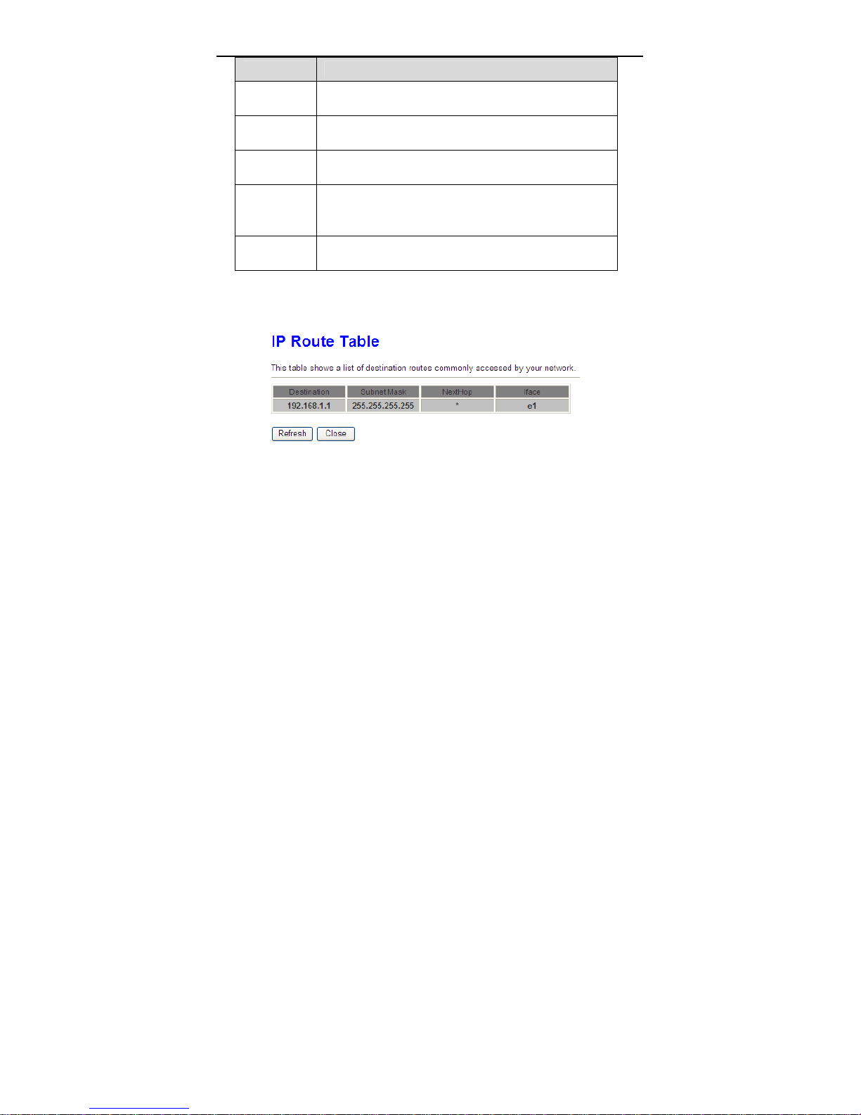
Click Show Routes, the page shown in the following figure appears. The table
shows a list of destination routes commonly accessed by your network.
Select a row in the Static Route Table and click it to
delete the row.
Click it, the IP Route Table appears. You can view a list
of destination routes commonly accessed by your
network.
A list of the previously configured static IP routes.
3.5.1.2 IPv6 Static Route
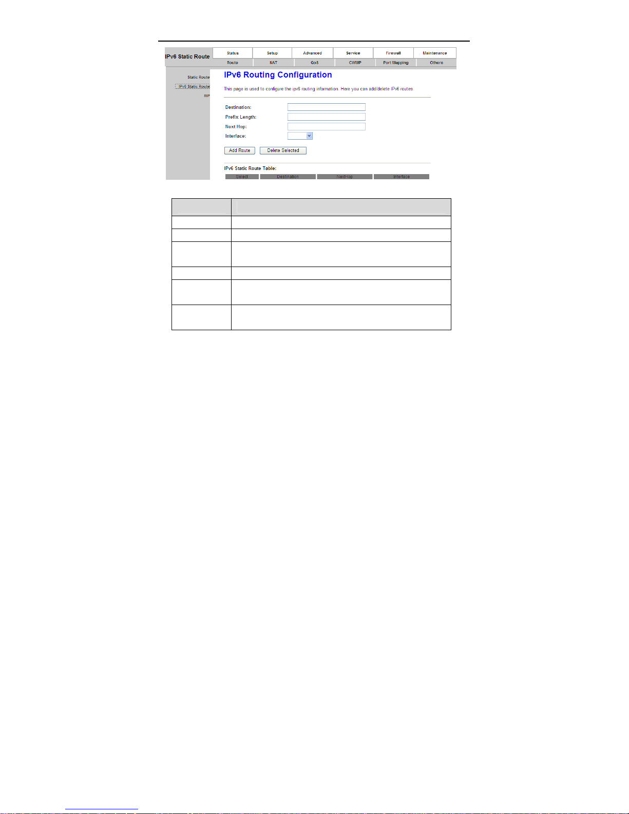
Click IPv6 Static Route in the left pane, the page shown in the following figure
appears. This page is used to configure the routing information. You can add or
delete IP routes.
43
Page 48
User Manual
The following table describes the parameters and buttons of this page.
Field Description
Destination Enter the IPv6 address of the destination device.
Prefix Length Enter the prefix length of the IPv6 address.
Next Hop Enter the IP address of the next hop in the IPv6 route to
the destination address.
Interface The interface for the specified route.
Add Route Click it to add the new static route to the IPv6 Static
Route Table.
Delete
Selected
Select a row in the IPv6 Static Route Table and click it to
delete the row.
3.5.1.3 RIP
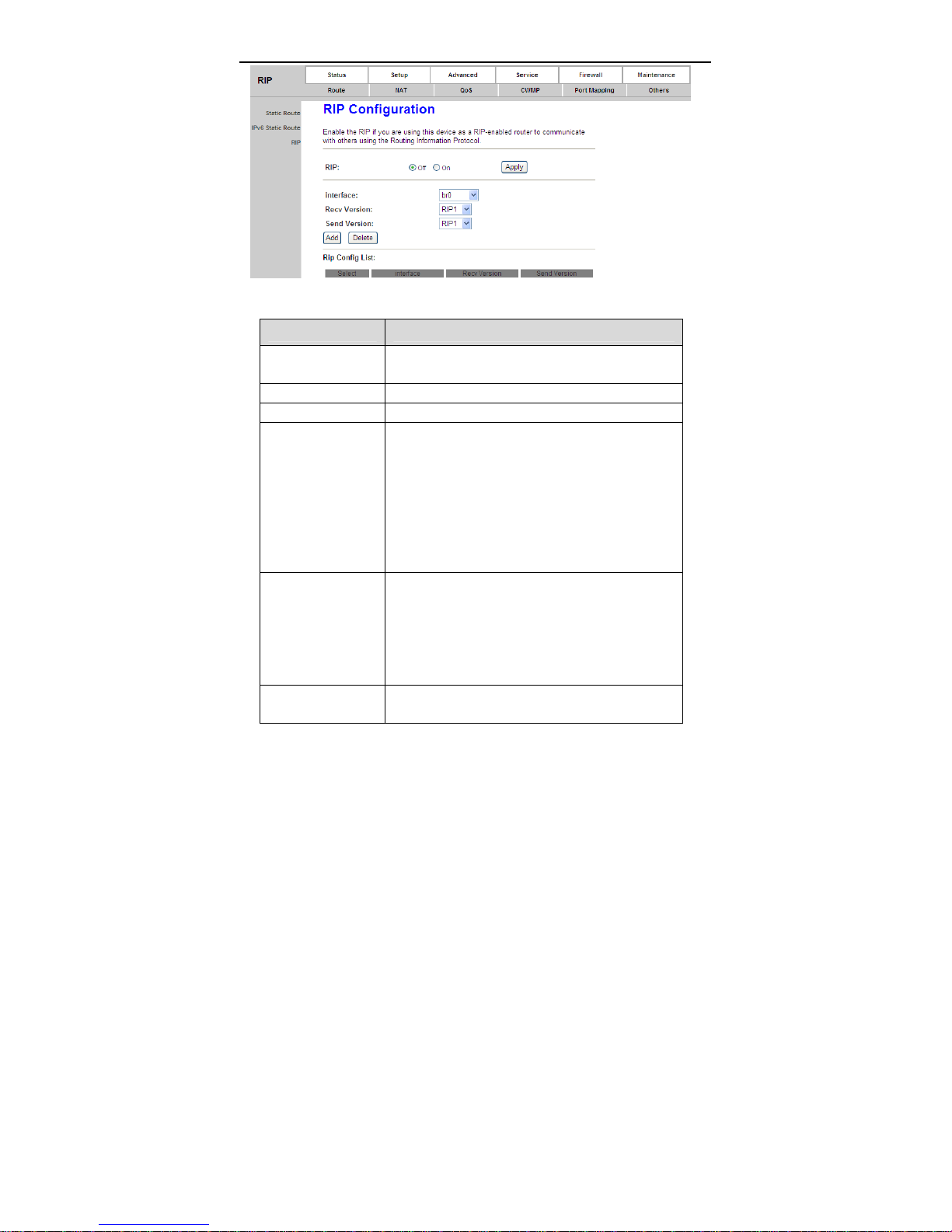
Click RIP in the left pane, the page shown in the following figure appears. If you
are using this device as a RIP-enabled router to communicate with others using
Routing Information Protocol (RIP), enable RIP. This page is used to select the
interfaces on your devices that use RIP, and the version of the protocol used.
44
Page 49
User Manual
The following table describes the parameters and buttons of this page.
Field Description
RIP Select On, the router communicates with other
RIP-enabled devices.
Apply Click it to save the settings of this page.
Interface Choose the router interface that uses RIP.
Recv Version Choose the interface version that receives RIP
messages. You can choose RIP1, RIP2, or Both.
Choose RIP1 indicates the router receives RIP
v1 messages.
Choose RIP2 indicates the router receives RIP
v2 messages.
Choose Both indicates the router receives RIP
v1 and RIP v2 messages.
Send Version The working mode for sending RIP messages. You
can choose RIP1 or RIP2.
Choose RIP1 indicates the router broadcasts
RIP1 messages only.
Choose RIP2 indicates the router multicasts
RIP2 messages only.
Add Click it to add the RIP interface to the Rip
Configration List.
45
Page 50
User Manual
Field Description
Delete Select a row in the Rip Configration List and click
it to delete the row.
3.5.2 NAT
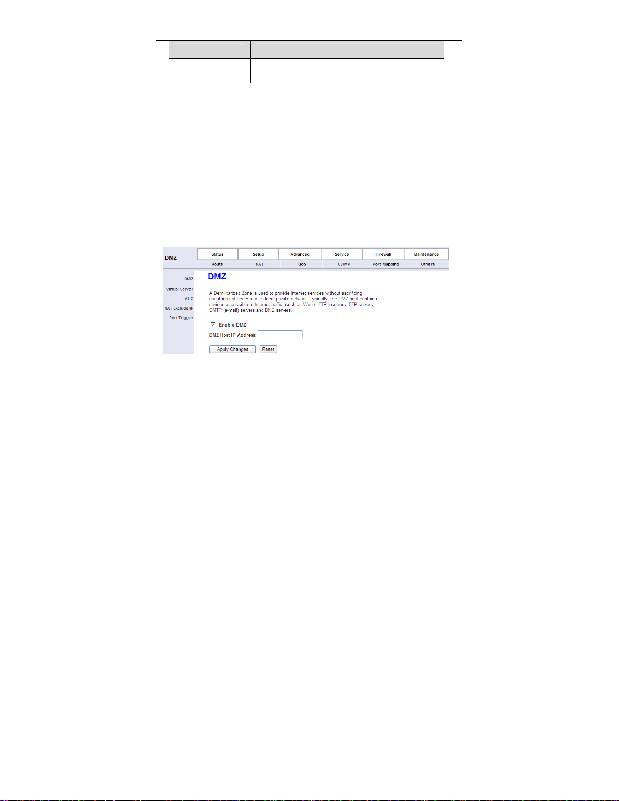
3.5.2.1 DMZ
Demilitarized Zone (DMZ) is used to provide Internet services without sacrificing
unauthorized access to its local private network. Ty pically, the DMZ host contains
devices accessible to Internet traffic, such as web (HTTP) servers, FTP servers,
SMTP (e-mail) servers and DNS servers.
Click DMZ in the left pane, the page shown in the following figure appears.
The following describes how to configure manual DMZ.
Step 1 Select Enable DMZ to enable this function.
Step 2 Enter an IP address of the DMZ host.
Step 3 Click Apply Changes to save the settings of this page temporarily.
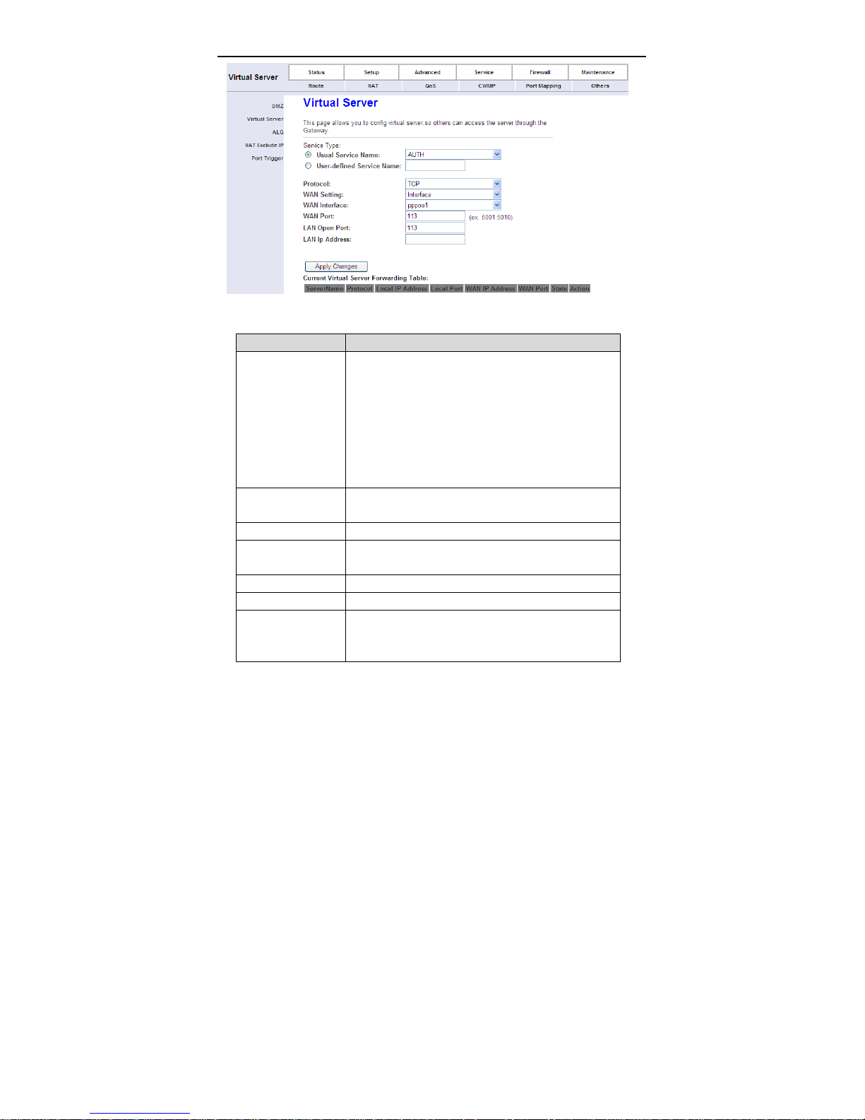
3.5.2.2 Virtual Server
Click Virtual Server in the left pane, the page shown in the following figure
appears.
46
Page 51
User Manual
The following table describes the parameters of this page.
Field Description
You can select the common service type, for
example, AUTH, DNS or FTP. You can also define a
service name.
Service Type
Protocol
WAN Setting You can choose Interface or IP Address.
WAN Interface
WAN Port Choose the access port on the WAN.
LAN Open Port Enter the port number of the specified service type.
LAN IP Address
If you select Usual Service Name, the
corresponding parameter has the default
settings.
If you select User-defined Service Name, you
need to enter the corresponding parameters.
Choose the transport layer protocol that the service
type uses. You can choose TCP or UDP.
Choose the WAN interface that will apply virtual
server.
Enter the IP address of the virtual server. It is in the
same network segment with LAN IP address of the
router.
47
Page 52
User Manual
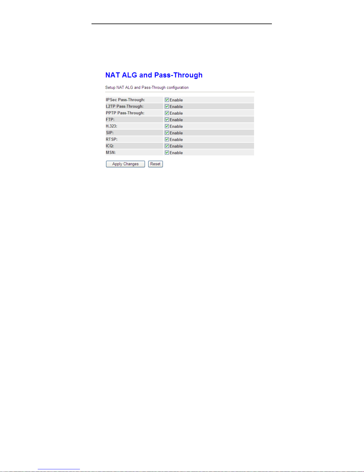
3.5.2.3 ALG
Click ALG in the left pane, the page shown in the following figure appears.
Choose the NAT ALG and Pass-Through options, and then click Apply
Changes.
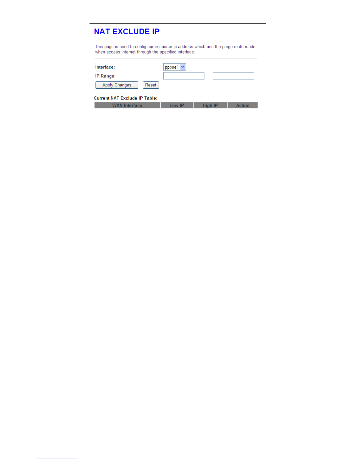
3.5.2.4 NAT Exclude IP
Click NAT Exclude IP in the left pane, the page shown in the following figure
appears.
In the page, you can configure some source IP addresses which use the purge
route mode when accessing internet through the specified interface.
48
Page 53
User Manual
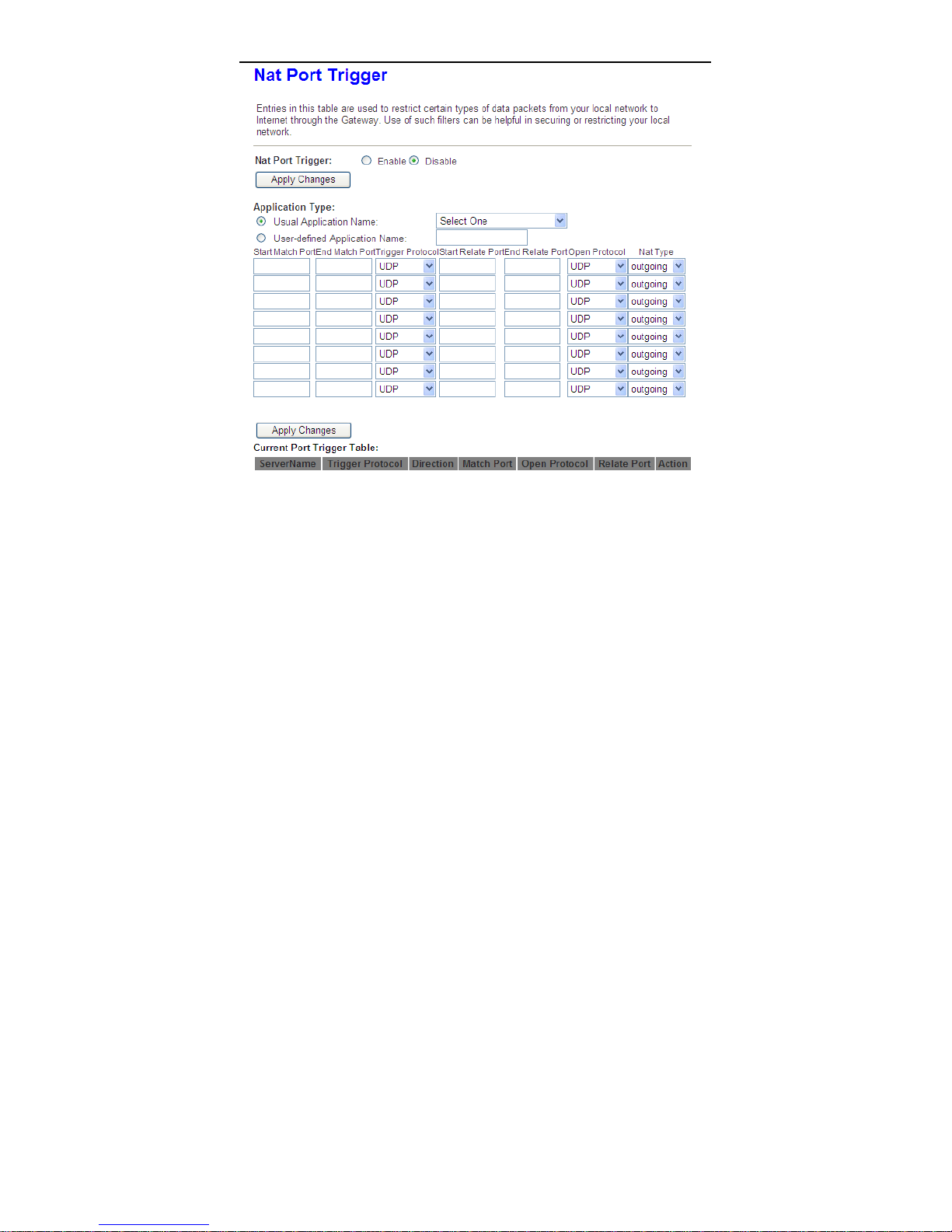
3.5.2.5 Port Trigger
Click Port Trigger in the left pane, the page shown in the following figure
appears.
49
Page 54
User Manual
Click the Usual Application Name drop-down menu to choose the application
you want to setup for port triggering. When you have chosen an application the
default Trigger settings will populate the table below.
If the application you want to setup isn’t listed, click the User-defined
Application Name radio button and type in a name for the trigger in the Custom
application field. Configure the Start Match Port, End Match Port, Trigger
Protocol, Start Rela te Port, End Relate Port, Open Protocol and Nat type
settings for the port trigger you want to configure.
When you have finished click the Apply changes button.
50
Page 55
User Manual
3.5.3 QoS
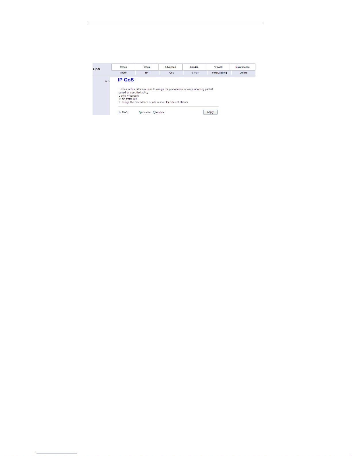
Choose Advanced > QoS, the page shown in the following figure appears.
Entries in the QoS Rule List are used to assign the precedence for each
incoming packet based on physical LAN port, TCP/UDP port number, source IP
address, destination IP address and other information.
Step 1 Enable IP QoS and click Apply to enable IP QoS function.
Step 2 Click add rule to add a new IP QoS rule.
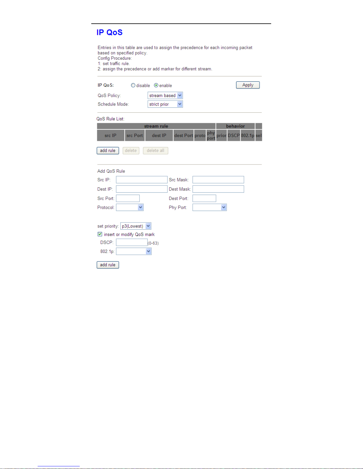
The page shown in the following figure appears.
51
Page 56
User Manual
52
Page 57

User Manual
The following table describes the parameters and buttons of this page.
Field Description
IP QoS Select to enable or disable IP QoS function. You n eed
to enable IP QoS if you want to configure the
parameters of this page.
QoS Policy You can choose stream based, 802.1p based or
DSCP based.
Schedule Mode You can choose strict prior or WFQ (4:3:2:1).
Source IP The IP address of the source data packet.
Source Mask The subnet mask of the source IP address.
Destination IP The IP address of the destination data packet.
Destination
Mask
Source Port The port of the source data packet.
Destination Port The port of the destination data packet.
Protocol The protocol responds to the IP QoS rules. You can
Physical Port The LAN interface responds to the IP QoS rules.
Set priority The priority of the IP QoS rules. P0 is the highest
802.1p You can choose from 0 to 7.
delete Select a row in the QoS Rule list and click it to delete
delete all Select all the rows in the QoS Rule list and click it to
The subnet mask of the destination IP address.
choose TCP, UDP, ICMP or TCP/UDP.
priority and P3 is the lowest.
the row.
delete the rows.
3.5.4 CWMP
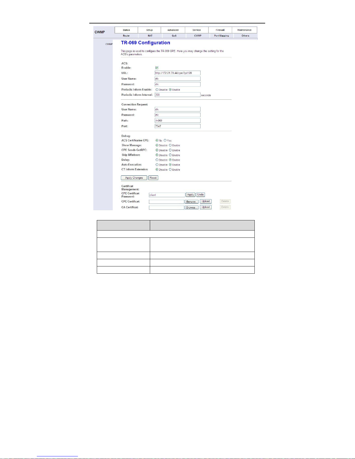
Choose Advanced > CWMP, the page shown in the following page appears. In
this page, you can configure the TR-069 CPE.
53
Page 58
User Manual
The following table describes the parameters of this page:
Field Description
ACS
URL The URL of the auto-configuration server to
connect to.
User Name The user name for logging in to the ACS.
Password The password for logging in to the ACS.
Periodic Inform Enable Select Enable to periodically connect to the
54
Page 59

User Manual
Field Description
ACS to check whether the configuration
updates.
Periodic Inform
Interval
Connection Request
User Name The connection usrname provided by TR-069
Password The connection password provided by TR-069
Debug
Show Message Select Enable to display ACS SOAP messages
CPE sends GetRPC Select Enbale, the router contacts the ACS to
Skip MReboot Specify whether to send an MReboot event
Delay Specify whether to start the TR-069 program
Auto-Execution Specify whether to automatically start the
Specify the amount of time between
connections to ACS.
service.
service.
on the serial console.
obtain configuration updates.
code in the inform message.
after a short delay.
TR-069 after the router is powered on.
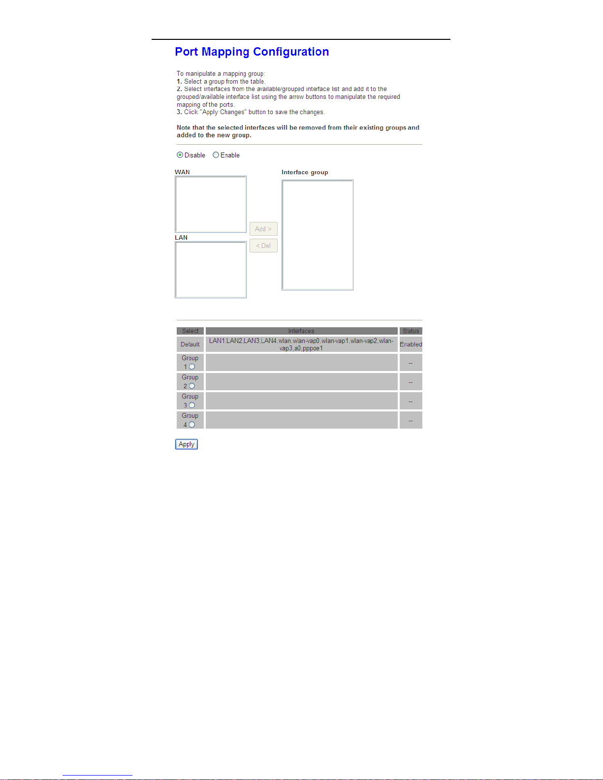
3.5.5 Port Mapping
Choose Advanced > Port Mapping, the page shown in the following page
appears.
55
Page 60
User Manual
56
Page 61
User Manual
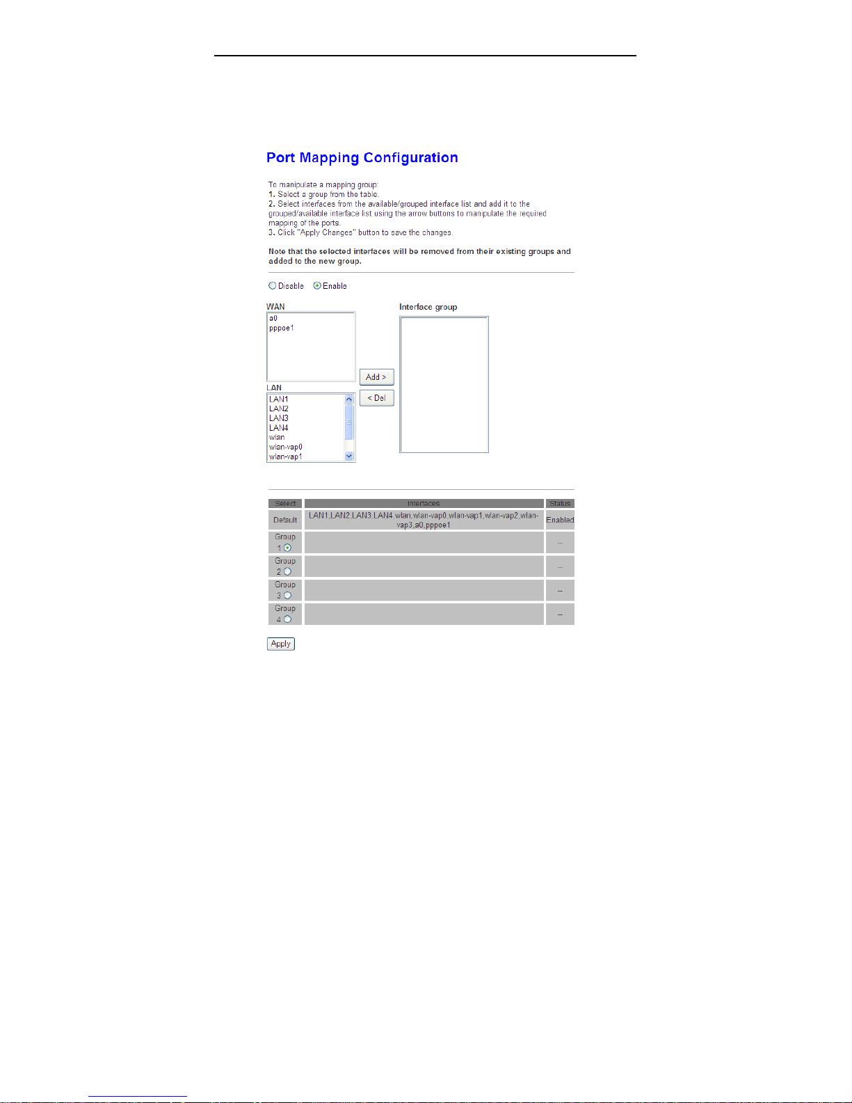
Creat four rules through Group1 to Group4. The procedure is as follows:
Step 1 Select Enable to enable port mapping.
Step 2 Select Group1. Then the interfaces are added in the WAN and LAN
table.
The following page appears.
57
Page 62
User Manual
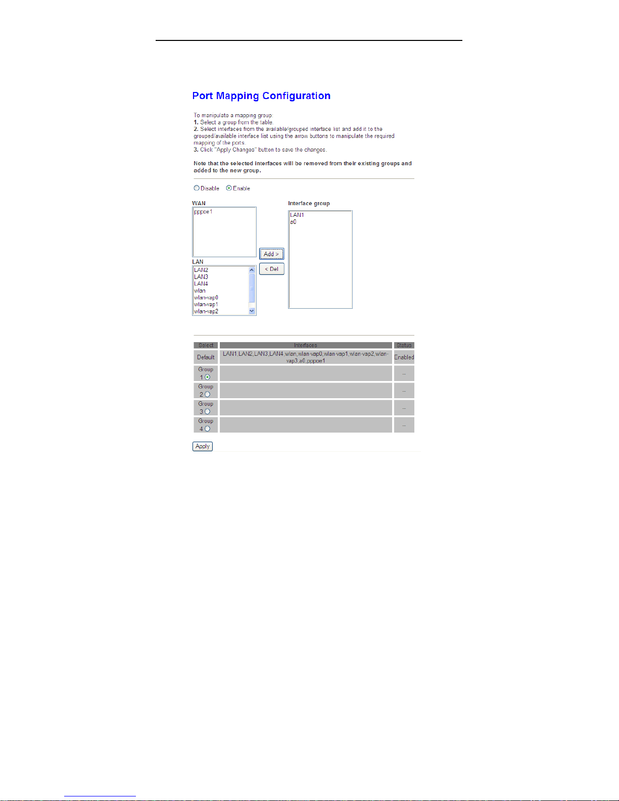
Step 3 Select the interfaces that are respectively added to WAN and LAN.
Press Ctrl while selecting multiple interfaces.
Step 4 Click Add to add the interface to the rule.
The following page appears.
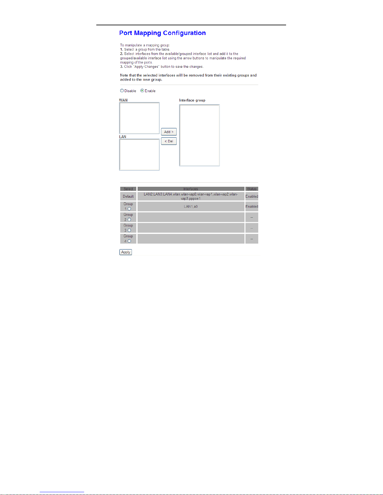
Step 5 Click Apply to apply the settings, and the following page appears.
58
Page 63
User Manual
In this example, only interfaces of a0 and LAN1 can communicate with each
other. That is, only LAN1 can access the Internet through a0 interface.
59
Page 64
User Manual
3.5.6 Others
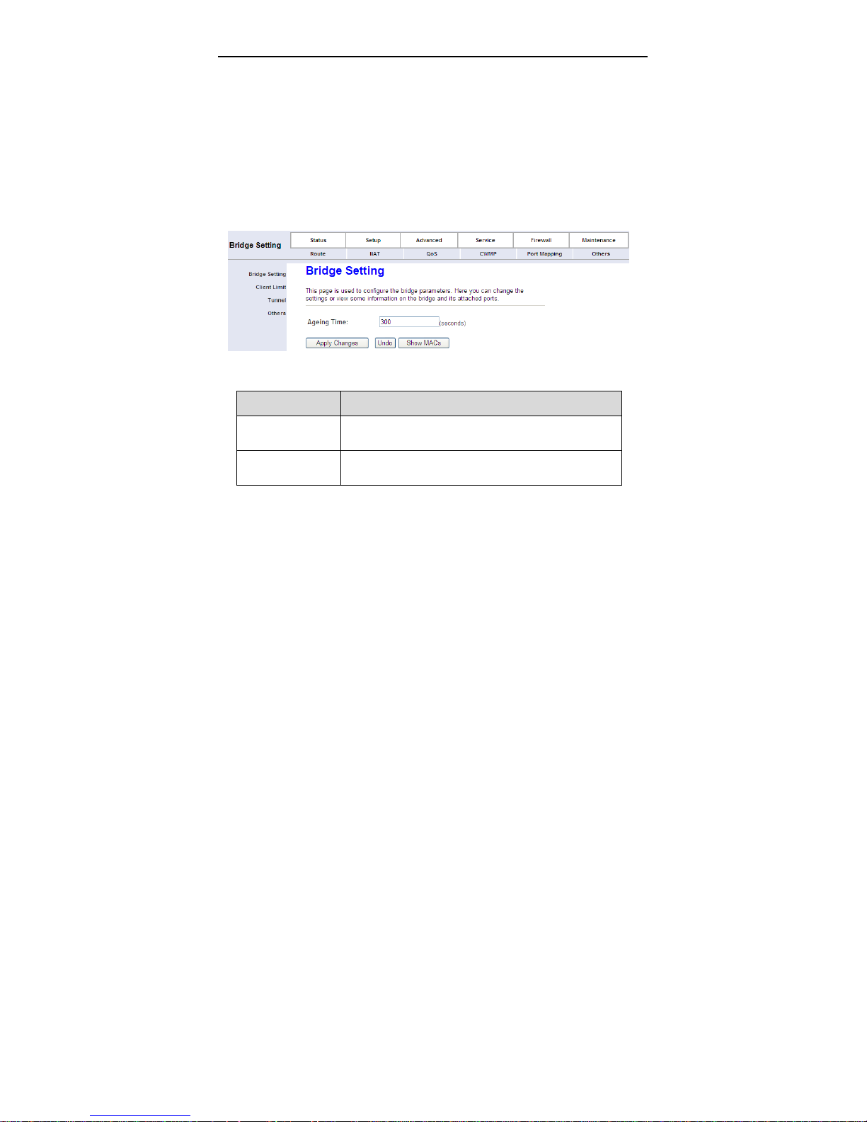
Choose Advanced > Others. The page that is displayed contains Bridge
Setting, Client Limit, Tunnel and Others.
3.5.6.1 Bridge Setting
Choose Bridge Setting in the left pane, the page shown in the following figure
appears. This page is used to configure the bridge parameters. You can change
the settings or view some information on the bridge and its attached ports.
The following table describes the parameters and button of this page:
Field Description
Ageing Time If the host is idle for 300 seconds (default value), its
entry is deleted from the bridge table.
Show MACs Click it to show a list of the learned MAC addresses
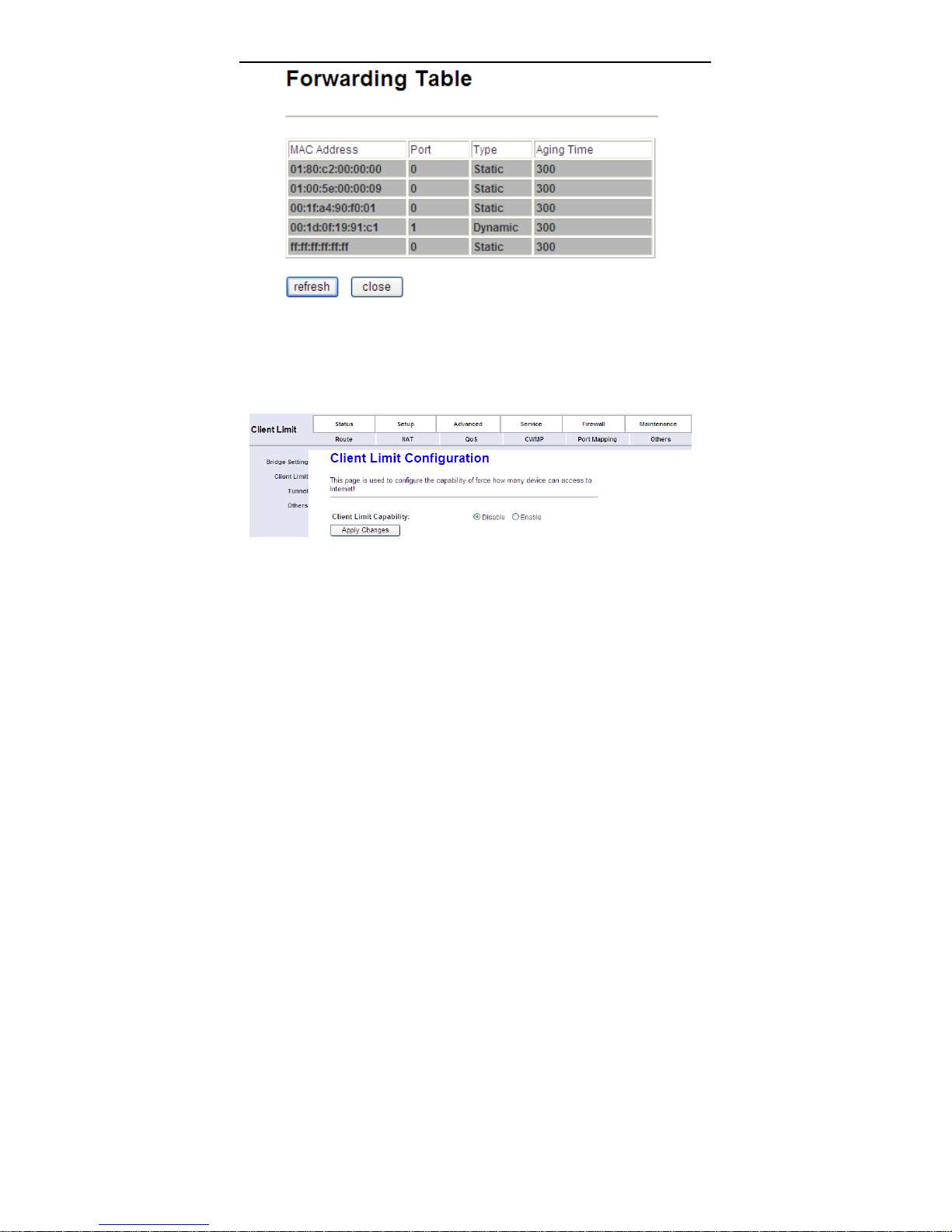
for the bridge.
Click Show MACs, the page shown in the following figure appears. This table
shows a list of learned MAC addresses for this bridge.
60
Page 65
User Manual
3.5.6.2 Client Limit
Choose Client Limit in the left pane, the page shown in the following figure
appears. This page is used to configure the capability of forcing how many
devices can access to the Internet.
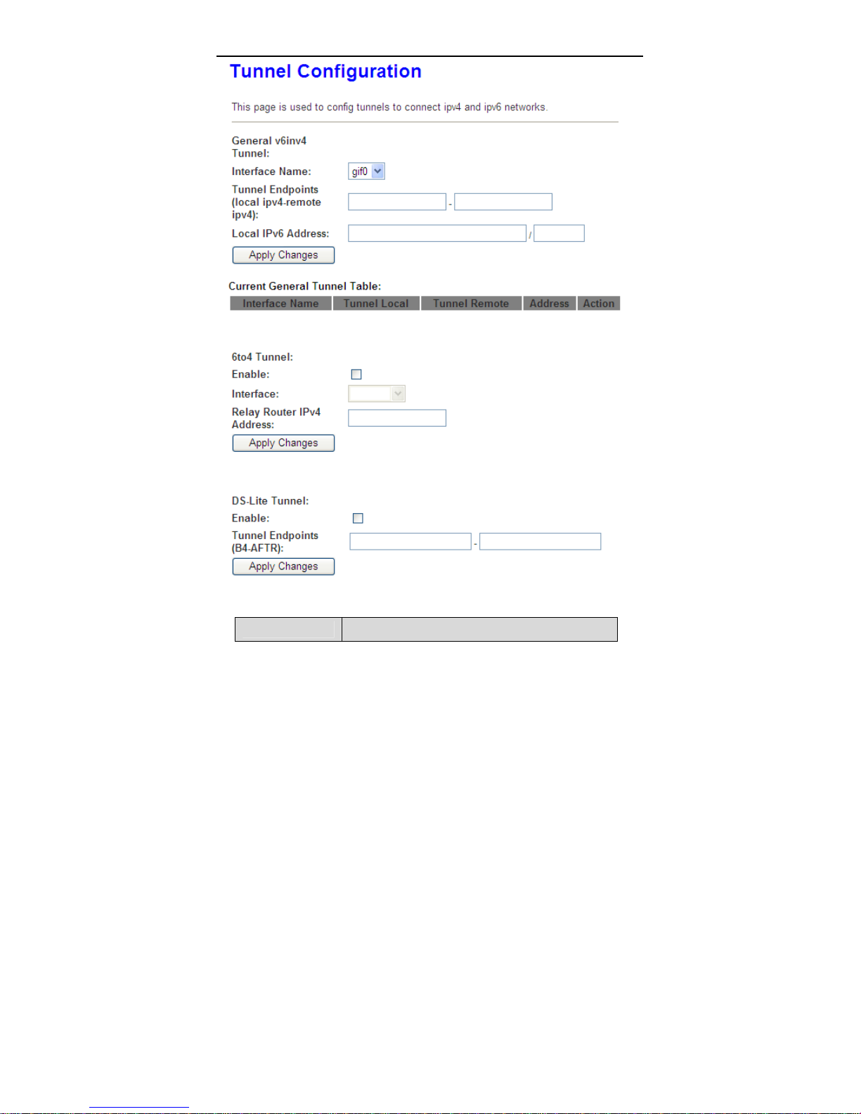
3.5.6.3 Tunnel
Choose Tunnel i n the left pane, the page shown in the following figure appears.
You may configure tunnels to connect ipv4 and ipv6 networks.
61
Page 66
User Manual
The following table describes the parameters and button of this page.
Field
Description
62
Page 67
User Manual
General v6inv4
Tunnel
Interface Name
Tunnel Endpoints Specify the ipv4 address for tunnel endpoints
Local IPv6
Address
Current General
Tunnel Table
6to4 Tunnel Enable or disable special tunnel
Interface Select current wan interface used as tunnel interface
Enable Enable or disable the DS-Lite tunnel
Tunnel Endpoints Specify the B4 and AFTR ipv6 address
Specify the general v6inv4 tunnel, ipv6 packet is
encapsulated in ipv4 packets,
Select the tunnel interface name, user can set 2
v6inv4 tunnel
Specify the ipv6 address for tunnel local
Display current general v6inv4 tunnel setting
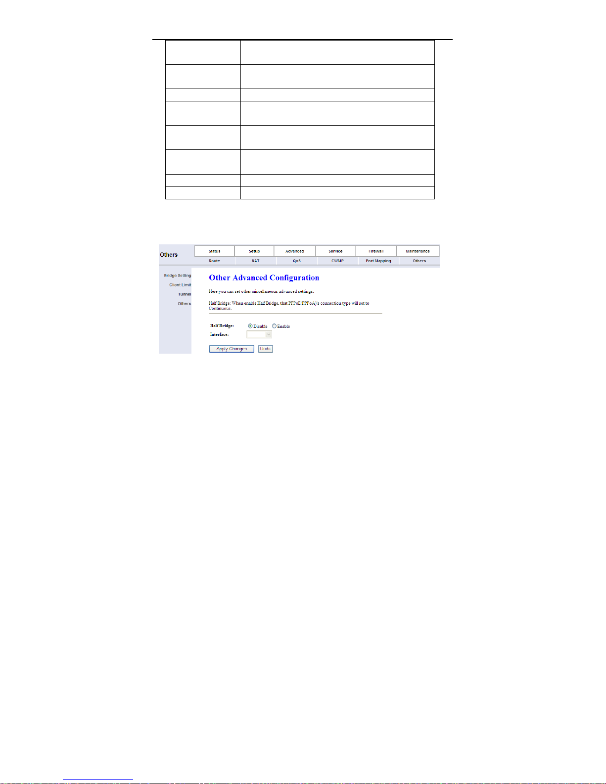
3.5.6.4 Others
Choose Others in the left pane, the page shown in the following figure appears.
3.6 Service
In the navigation bar, click Service. The tab Service contains IGMP, UPnP,
SNMP, DNS and DDNS.
3.6.1 IGMP
Choose Service > IGMP, and the following page appears. The page that is
displayed contains IGMP Proxy and MLD.
63
Page 68
User Manual
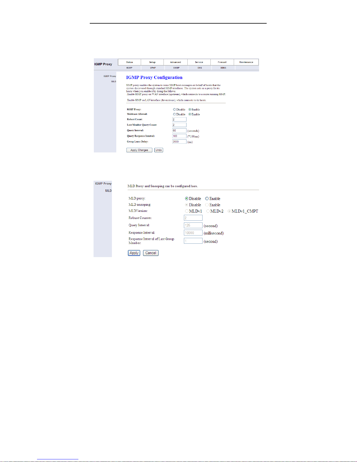
3.6.1.1 IGMP Proxy
Click IGMP Proxy in the left pane, the page shown in the following figure appears.
In this page, you can enable or disable IGMP proxy. If you disable IGMP proxy,
the modem will discard all the received multicast data packets.
3.6.1.2 IGMP MLD
Click MLD in the left pane, the page shown in the following figure appears.
The following table describes the parameters and button of this page.
64
Page 69
User Manual
Field
MLD proxy Mld proxy enable, only for route mode
MLD snooping Mld snooping enable
Allows tuning for the expected packet loss on a link.
Robust Counter
Query Interval
Response Interval
Response Interval
of Last Group
Member
It determines how many times a startup query
should be xmitted.
Denotes the interval between general queries send
by the querier.
Used to calculate the max response code inserted
into the periodic general queries.
Max response delay used to calculate the max
response code inserted into multicast address
specific queries sent in response to version 1
multicast listener done messages. It is also the max
response delay used to calculate the max response
code inserted into multicast address and source
specific query messages.
Description
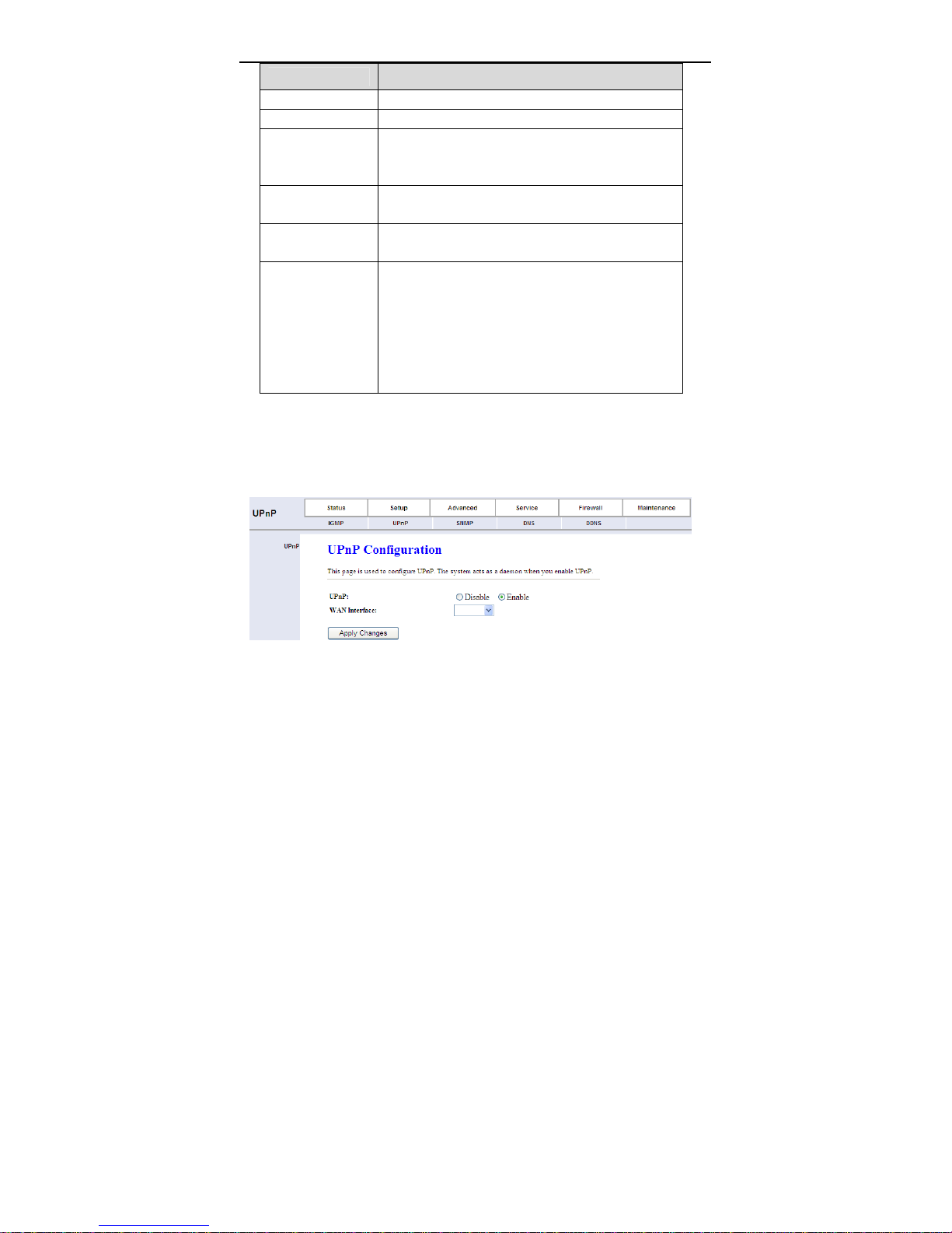
3.6.2 UPnP
Click UPnP in the left pane, the page shown in the following figure appears. The
system acts as a daemon after you enable UPnP.
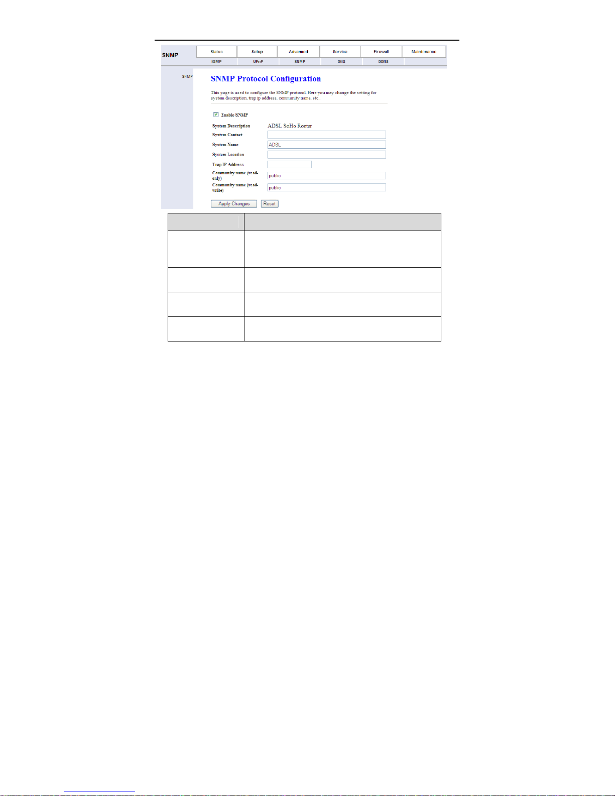
3.6.3 SNMP
Click SNMP in the left pane, the page shown in the following figure appears. You
can configure the SNMP parameters.
65
Page 70
Field
Enable SNMP
Trap IP Address
Community name
(read-only)
Community name
(read-write)
User Manual
Description
Select it to enable SNMP function. You need to
enable SNMP, and then you can configure the
parameters of this page.
Enter the trap IP address. The trap information is
sent to the corresponding host.
The network administrators must use this password
to read the information of this router.
The network administrators must use this password
to configure the information of the router.
3.6.4 DNS
Domain Name System (DNS) is an Internet service that translates the domain
name into IP address. Because the domain name is alphabetic, it is easier to
remember. The Internet, however, is based on IP addresses. Every time you use
a domain name, DNS translates the name into the corresponding IP address. For
example, the domain name www.example.com might be translated to
198.105.232.4. The DNS has its own network. If one DNS server does not know
66
Page 71
User Manual
how to translate a particular domain name, it asks another one, and so on, until
the correct IP address is returned.
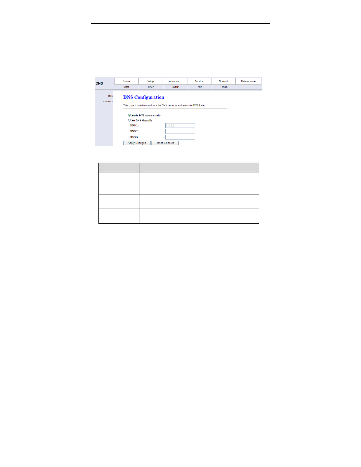
Choose Service > DNS. The DNS page that is displayed contains DNS and IPv6
DNS.
3.6.4.1 DNS
Click DNS in the left pane, and the page shown in the following figure appears.
The following table describes the parameters and buttons of this page.
Field Description
Attain DNS
Automatically
Set DNS
Manually
Apply Changes Click it to save the settings of this page.
Reset Selected Click it to start configuring the paremters in this page.
Select it, the router accepts the first received DNS
assignment from one of the PPPoA, PPPoE or MER
enabled PVC(s) during the connection establishment.
Select it, enter the IP addresses of the primary and
secondary DNS server.
3.6.4.2 IPv6 DNS
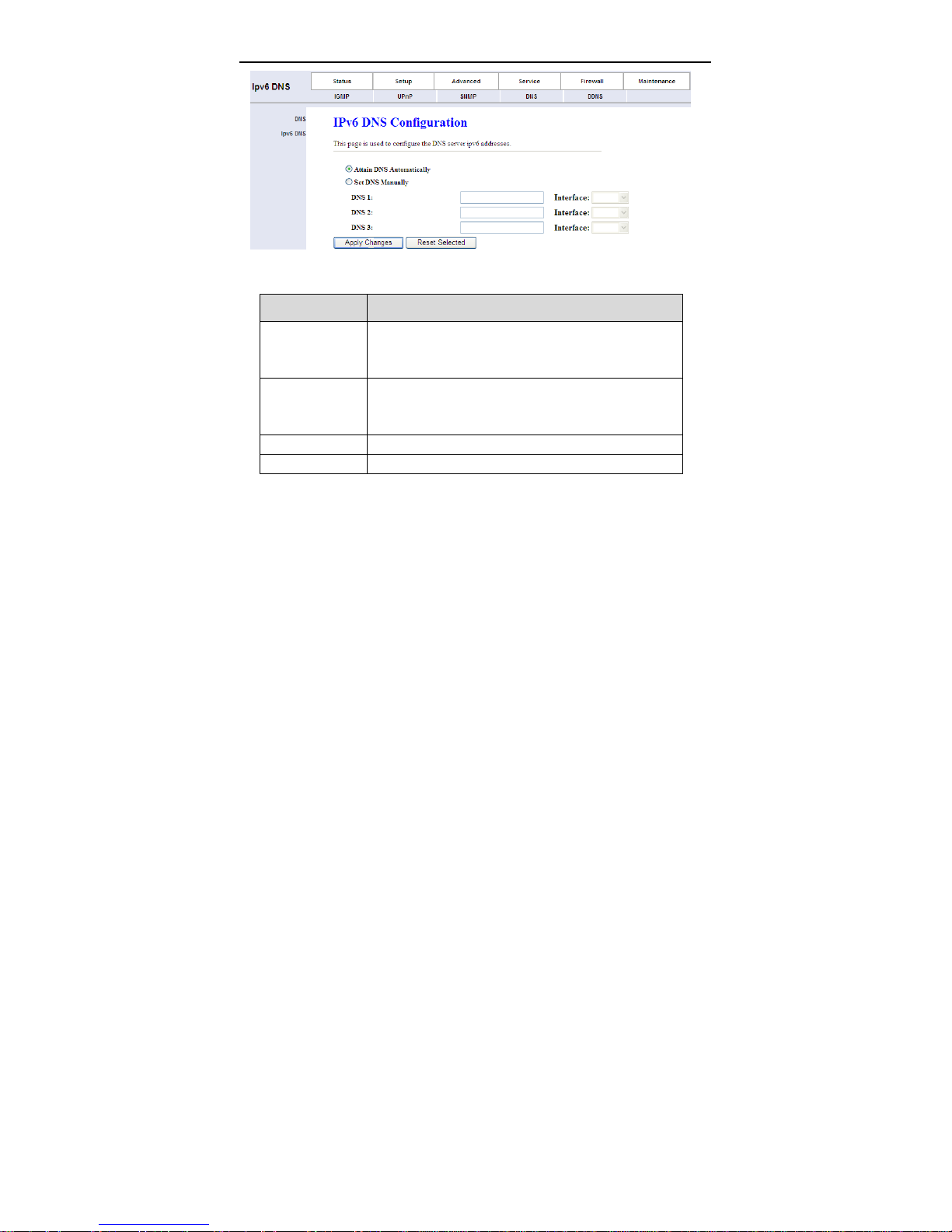
Click IPv6 DNS in the left pane, and the page shown in the following figure
appears.
67
Page 72
User Manual
The following table describes the parameters and buttons of this page.
Field Description
Attain DNS
Automatically
Set DNS
Manually
Apply Changes Click it to save the settings of this page.
Reset Selected Click it to start configuring the paremters in this page.
Select it, the router accepts the first received DNS
assignment from one of the PPPoA, PPPoE or MER
enabled PVC(s) during the connection establishment.
Select it, enter the IP addresses and choose the WAN
interface of the primary, the secondary and the tertiary
DNS server.
3.6.5 DDNS
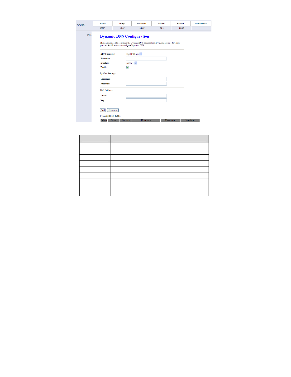
Choose Service > DDNS, the page shown in the following figure appears. This
page is used to configure the dynamic DNS address from DynDNS.org or TZO.
You can add or remove to configure dynamic DNS.
68
Page 73
User Manual
The following table describes the parameters of this page.
Field Description
DDNS provider
Host Name The DDNS identifier.
Interface The WAN interface of the router.
Enable Enable or disable DDNS function.
Username The name provided by DDNS provider.
Password The password provided by DDNS provider.
Email The email provided by DDNS provider.
Key The key provided by DDNS provider.
Choose the DDNS provider name. You can choose
DynDNS.org or TZO.
3.7 Firewall
69
Page 74
User Manual
3.7.1 MAC Filter
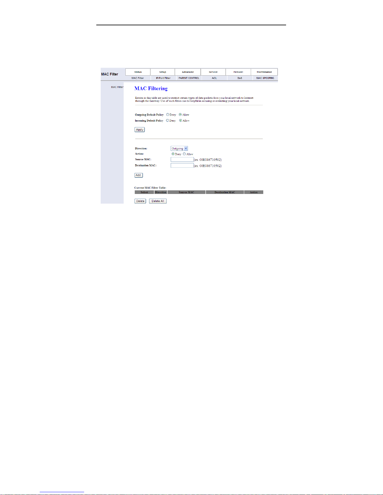
Click MAC Filter in the left pane, the page shown in the following figure appears.
Entries in the table are used to restrict certain types of data packets from your
local network to Internet through the gateway. These filters are helpful in securing
or restricting your local network.
3.7.2 IP/Port Filter
Choose Firewall > IP/Port Filter, the page shown in the following figure appears.
The page that is displayed contains IP/Port Filter and IPv6/Port Filter.
3.7.2.1 IP/Port Filter
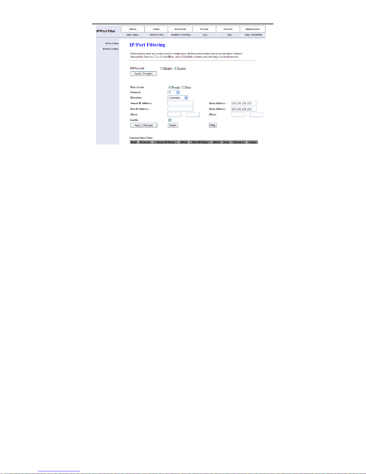
Click IP/Port Filter in the left pane, the page shown in the following figure
appears. Entries in the table are used to restrict certain types of data packets
through the gateway. These filters are helpful in securing or restricting your local
network.
70
Page 75
User Manual
3.7.2.2 IPv6/Port Filter
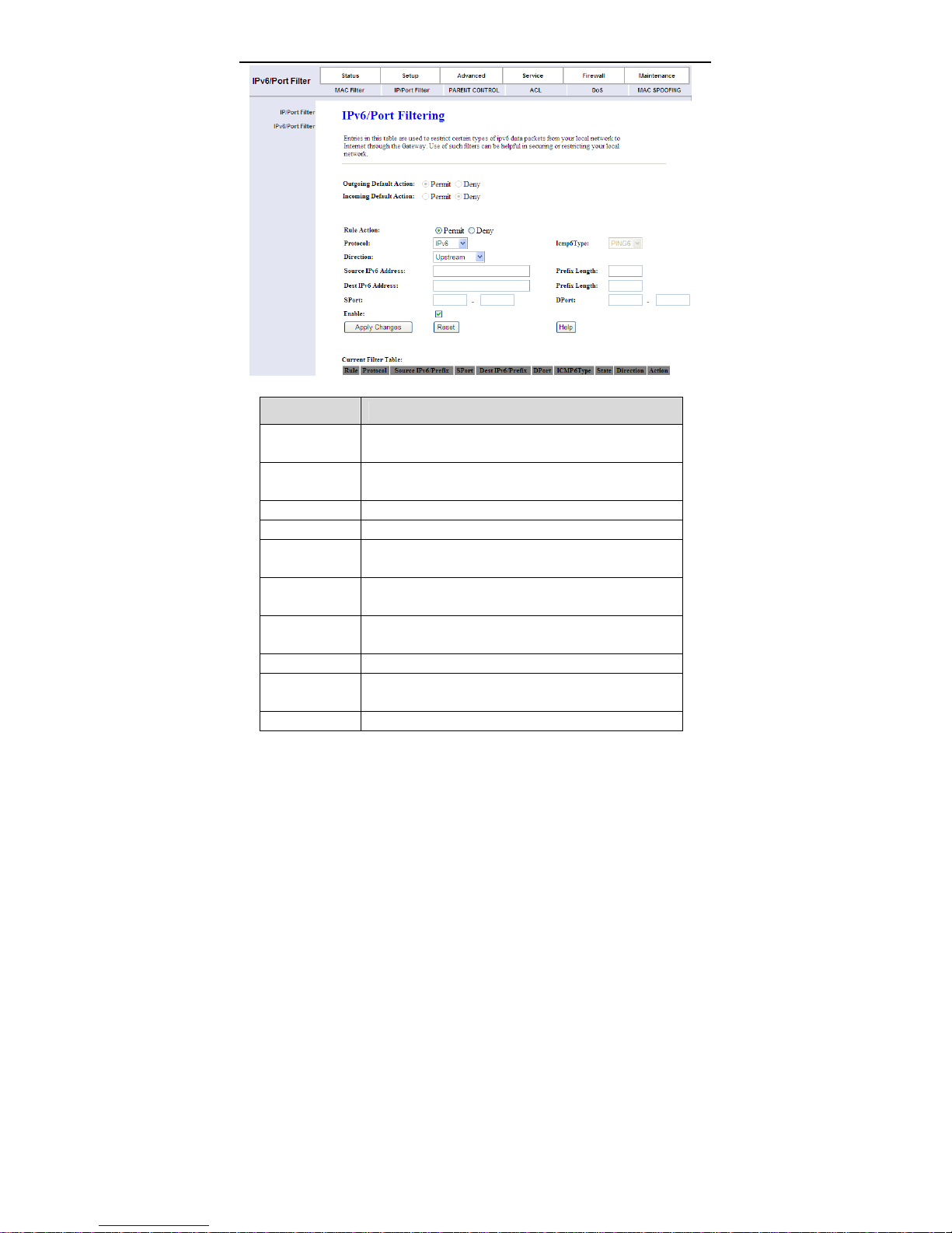
Click IPv6/Port Filter in the left pane, the page shown in the following figure
appears. Entries in this table are used to restrict certain types of ipv6 data
packets from your local network to the Internet through the Gateway.
71
Page 76
User Manual
The following table describes the parameters of this page.
Field Description
Outgoing
Default Action
Incoming
Default Action
Rule Action Specify the rule action: Permit or Deny
Protocol Specify the rule protocols: IPv6, ICMP6,TCP or UDP
Icmp6Type
Direction
Source IPv6
Address
Prefix Length Specify the source ipv6 address prefix length
Dest IPv6
Address
Prefix Length Specify the destination ipv6 address prefix length
Display current lan to wan default action
Display current wan to lan default action
When protocol is selected ICMP6, user specify icmp6
type, now only support PING6
“Upstream” means lan to wan; “Downstream” means
wan to lan.
Specify the source ipv6 address
Specify the destination ipv6 address
72
Page 77
User Manual
Field Description
Sport Specify source port when select TCP or UDP
DPort Specify destination port when select TCP or UDP
Enable Enable or disable this filter rule
Apply
Changes
Reset Reset above items
Add the rule to system
3.7.3 Parent Control
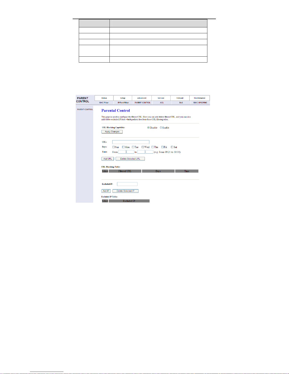
Choose Firewall > PARENT CONTROL, the page shown in the following figure
appears. In this page, you can block the specil URL in the special time.
73
Page 78

User Manual
3.7.4 ACL
Choose Firewall > ACL, the page shown in the following figure appears. The
page that is displayed contains ACL and IPv6 ACL.
3.7.4.1 ACL
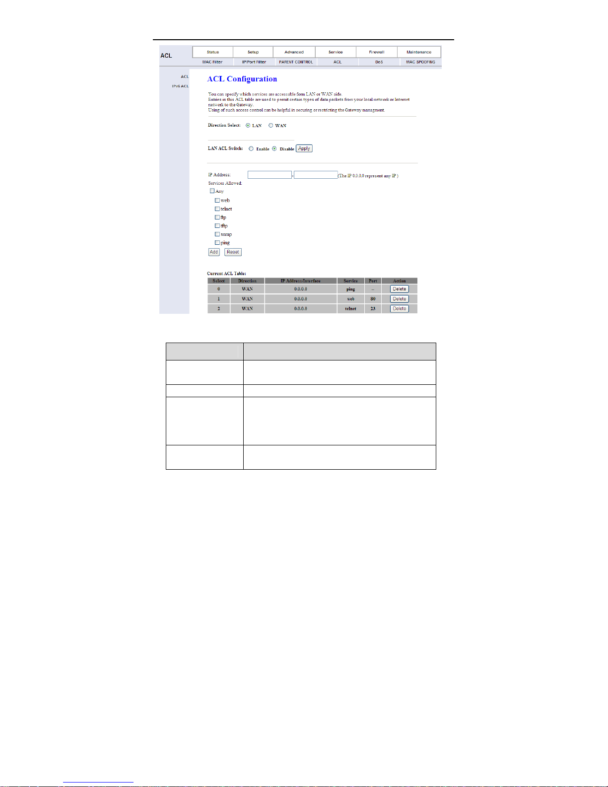
Click ACL in the left pane, the page shown in the following figure appears. In this
page, you can permit the data packets from LAN or WAN to access the router.
Y ou can configure the IP address for Access Control List (ACL). If ACL is enabled,
only the effective IP address in the ACL can access the router.
Note:
If you select Enable in ACL capability, ensure that your host IP address is in
ACL list before it takes effect.
74
Page 79
User Manual
The following table describes the parameters and buttons of this page.
Field Description
Direction Select
LAN ACL Switch Select it to enable or disable ACL function.
IP Address
Services Allowed
Select the router interface. You can select LAN or
WAN. In this example, LAN is selected.
Enter the IP address of the specified interface. Only
the IP address that is in the same network segment
with the IP address of the specified interface can
access the router.
You can choose the following services from LAN:
Web, Telnet, FTP, TFTP, SNMP or PING. You can
75
Page 80
User Manual
Field Description
also choose all the services.
Add
Reset Click it to refresh this page.
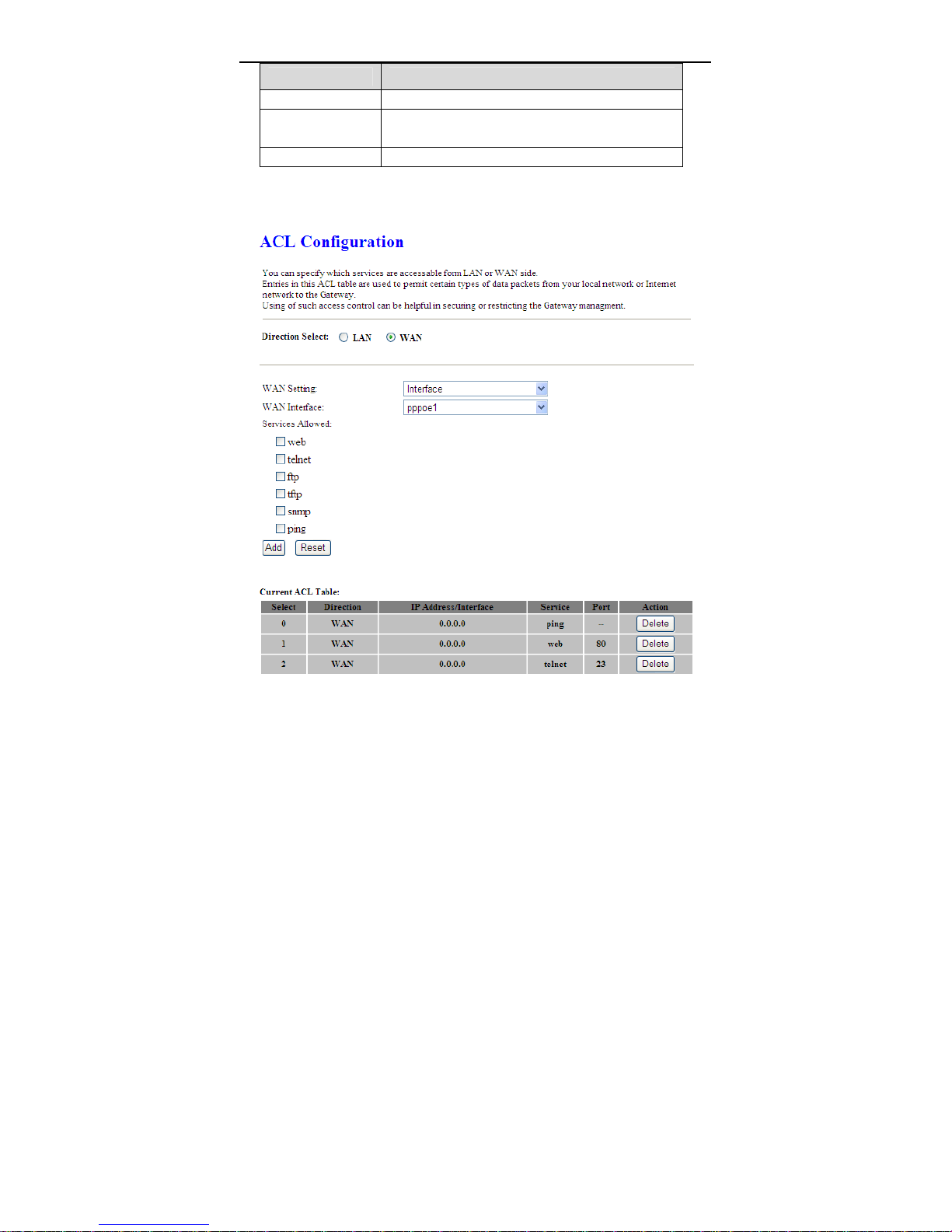
Set direction of the data packets to WAN, the page shown in the following figure
appears.
After setting the parameters, click it to add an entry
to the Current ACL Table.
The following table describes the parameters and buttons of this page.
76
Page 81

User Manual
Field Description
Direction Select
WAN Setting You can choose Interface or IP Address.
WAN Interface
IP Address
Services Allowed
Add
Reset Click it to refresh this page.
Select the router interface. You can select LAN or
WAN. In this example, WAN is selected.
Choose the interface that permits data packets from
WAN to access the router.
Enter the IP address on the WAN. Only the IP
address that is in the same network segment with
the IP address on the WAN can access the router.
You can choose the following services from WAN:
Web, Telnet, FTP, TFTP, SNMP, or PING. You can
also choose all the services.
After setting the parameters, click it to add an entry
to the Current ACL Table.
3.7.4.2 IPv6 ACL
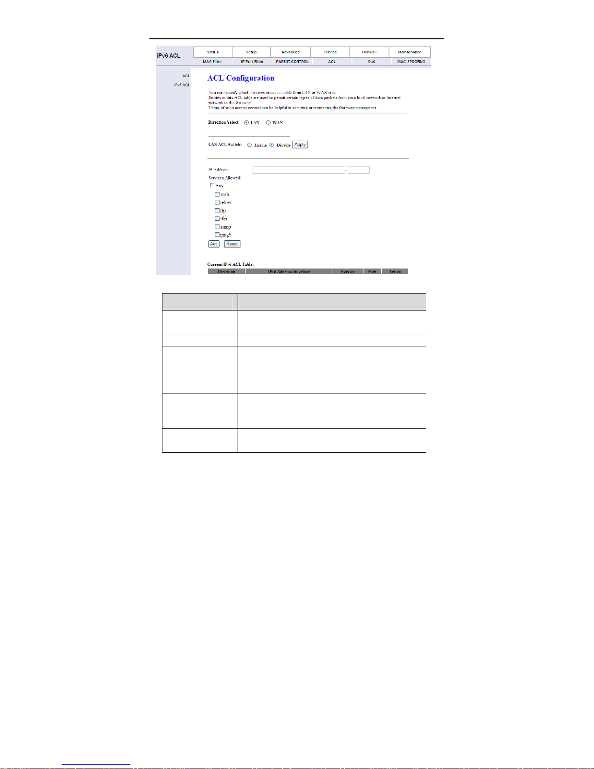
Click IPv6 ACL in the left pane, the page shown in the following figure appears.
Entries in this ACL table permit certain types of data packets from your local
network or the Internet to the Gateway.
77
Page 82
User Manual
The following table describes the parameters and buttons of this page.
Field Description
Direction Select
LAN ACL Switch Select it to enable or disable ACL function.
IP Address
Services Allowed
Add
Select the router interface. You can select LAN or
WAN. In this example, LAN is selected.
Enter the IPv6 address of the specified interface.
Only the IPv6 address that is in the same network
segment with the IPv6 address of the specified
interface can access the router.
You can choose the following services from LAN:
Web, Telnet, FTP, TFTP, SNMP or PING. You can
also choose all the services.
After setting the parameters, click it to add an entry
to the Current IPv6 ACL Table.
78
Page 83
User Manual
Field Description
Reset Click it to refresh this page.
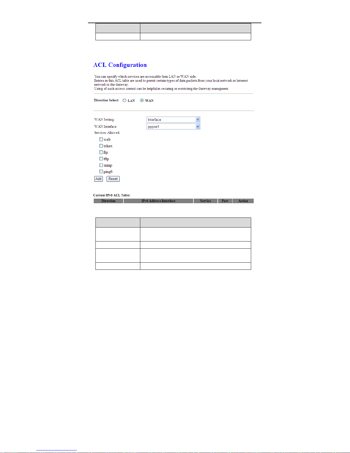
Set direction of the data packets to WAN, the page shown in the following figure
appears.
The following table describes the parameters and buttons of this page.
Field Description
Direction Select
WAN Setting You can choose Interface or IPv6 Address.
WAN Interface
IP Address Enter the IPv6 address on the WAN. Only the IPv6
Select the router interface. You can select LAN or
WAN. In this example, WAN is selected.
Choose the interface that permits data packets from
WAN to access the router.
79
Page 84

User Manual
Field Description
address that is in the same network segment with
the IPv6 address on the WAN can access the
router.
You can choose the following services from WAN:
Services Allowed
Add
Reset Click it to refresh this page.
Web, Telnet, FTP, TFTP, SNMP, or PING. You can
also choose all the services.
After setting the parameters, click it to add an entry
to the Current IPv6 ACL Table.
3.7.5 DoS
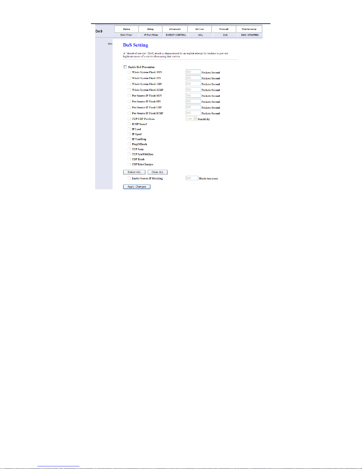
Denial-of-Service Attack (DoS attack) is a type of attack on a network that is
designed to bring the network to its knees by flooding it with useless traffic.
Choose Firewall > DoS, the page shown in the following figure appears. In this
page, you can prevent DoS attacks.
80
Page 85
User Manual
3.7.6 MAC Spoofing
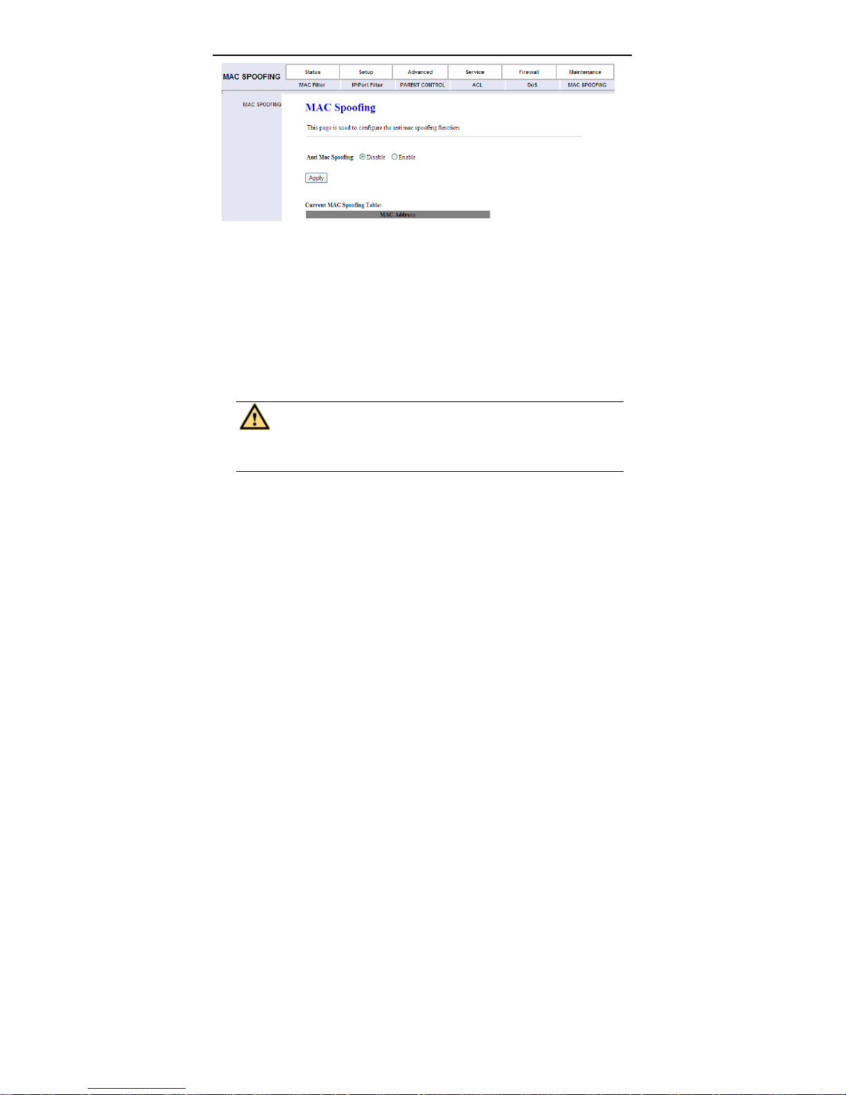
Choose Firewall > MAC SPOOFING, the page shown in the following figure
appears. In this page, you can configure the anti MAC spoofing function.
81
Page 86
User Manual
3.8 Maintenance
In the navigation bar, click Maintenance. The Maintenance page that is
displayed contains Update, Password, Reboot, Time, Log and Diagnostics.
3.8.1 Update
Choose Maintenance > Update. The Update page that is displayed contains
Firmware Update and Backup/Restore.
Caution:
Do not turn off the router or press the Reset button w hile the procedure
is in progress.
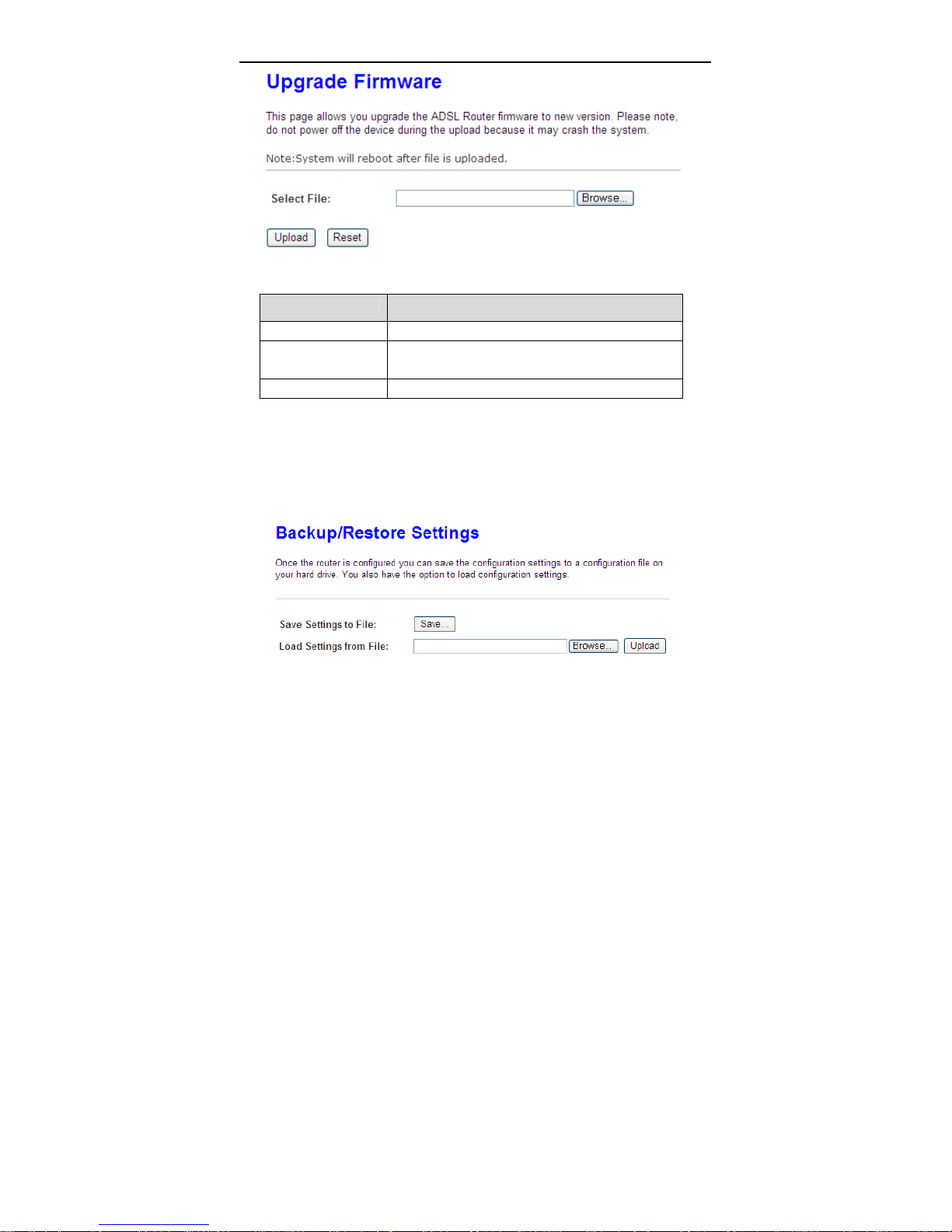
3.8.1.1 Firmware Update
Click Upgrade Firmware in the left pane, the page shown in the following figure
appears. In this page, you can upgrade the firmware of the router.
82
Page 87
User Manual
The following table describes the parameters and button of this page.
Field Description
Select File Click Browse to select the firmware file.
Upload
Reset Click it to starting selecting the firmware file.
After selecting the firmware file, click Upload to
starting upgrading the firmware file.
3.8.1.2 Backup/Restore
Click Backup/Restore in the left pane, the page shown in the following figure
appears. You can backup the current settings to a file and restore the settings
from the file that was saved previously.
83
Page 88
User Manual
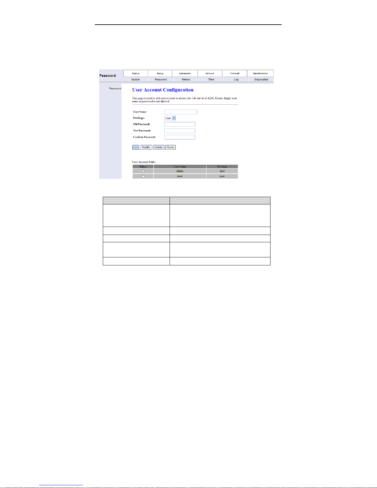
3.8.2 Password
Choose Maintenance > Password, the page shown in the following figure
appears. By default, the user name and password are tmadmin and tmadmin
espectively. The common user name and password are tmuser and tmuser
espectively.
The following table describes the parameters of this page.
Field Description
Choose the user name for accessing the
User Name
Privilege Choose the privilege for the account.
Old Password Enter the old password
New Password
Confirm Password Enter the new password again.
router. You can choose tmadmin or
tmuser
Enter the password to which you want to
change the old password.
84
Page 89
User Manual
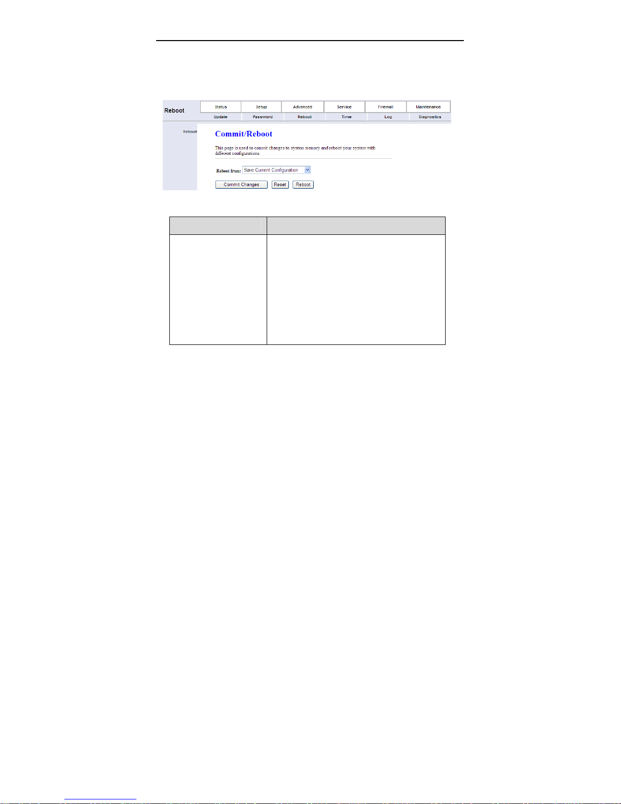
3.8.3 Reboot
Choose Maintenance > Reboot, the page shown in the following figure appears.
You can set the router reset to the default settings or set the router to commit the
current settings.
The following table describes the parameters and button of this page.
Field Description
You can choose Save Current Configura tion
or Factory Default Configuration. Click
Reboot to reboot the router.
Save Current Configuration: Save the
Reboot from
current settings, and then reboot the
router.
Factory Default Configuration: Reset to
the factory default settings, and then
reboot the the router.
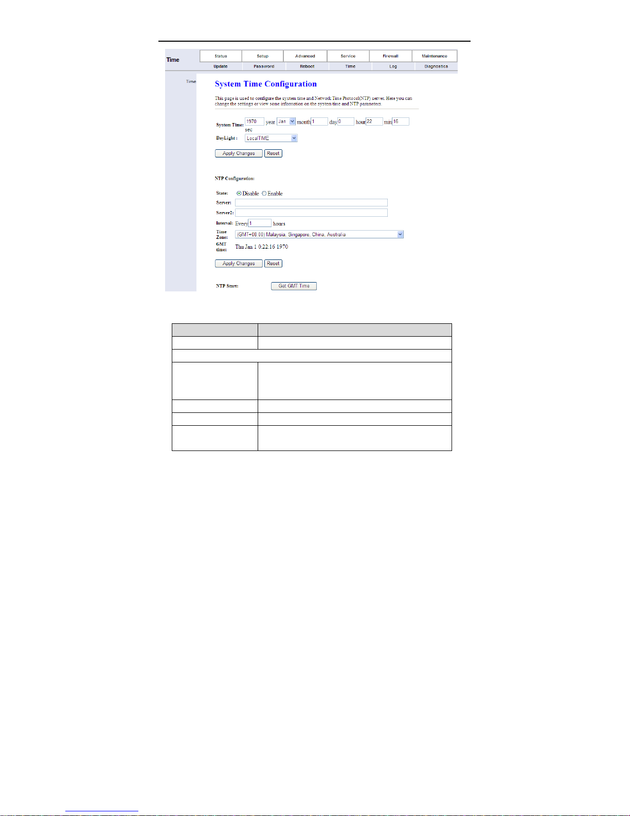
3.8.4 Time
Choose Maintenance > Time Zone, the page shown in the following figure
appears. You can configure the system time manually or get the system time
from the time server.
85
Page 90
User Manual
The following table describes the parameters of this page.
Field Description
System Time Set the system time manually.
NTP Configuration
Select enable or disable NTP function. You need
State
Server Set the primary NTP server manually.
Server2 Set the secondary NTP server manually.
Time Zone
to enable NTP if you want to configure the
parameters of NTP.
Choose the time zone in which area you are from
the drop down list.
86
Page 91
User Manual
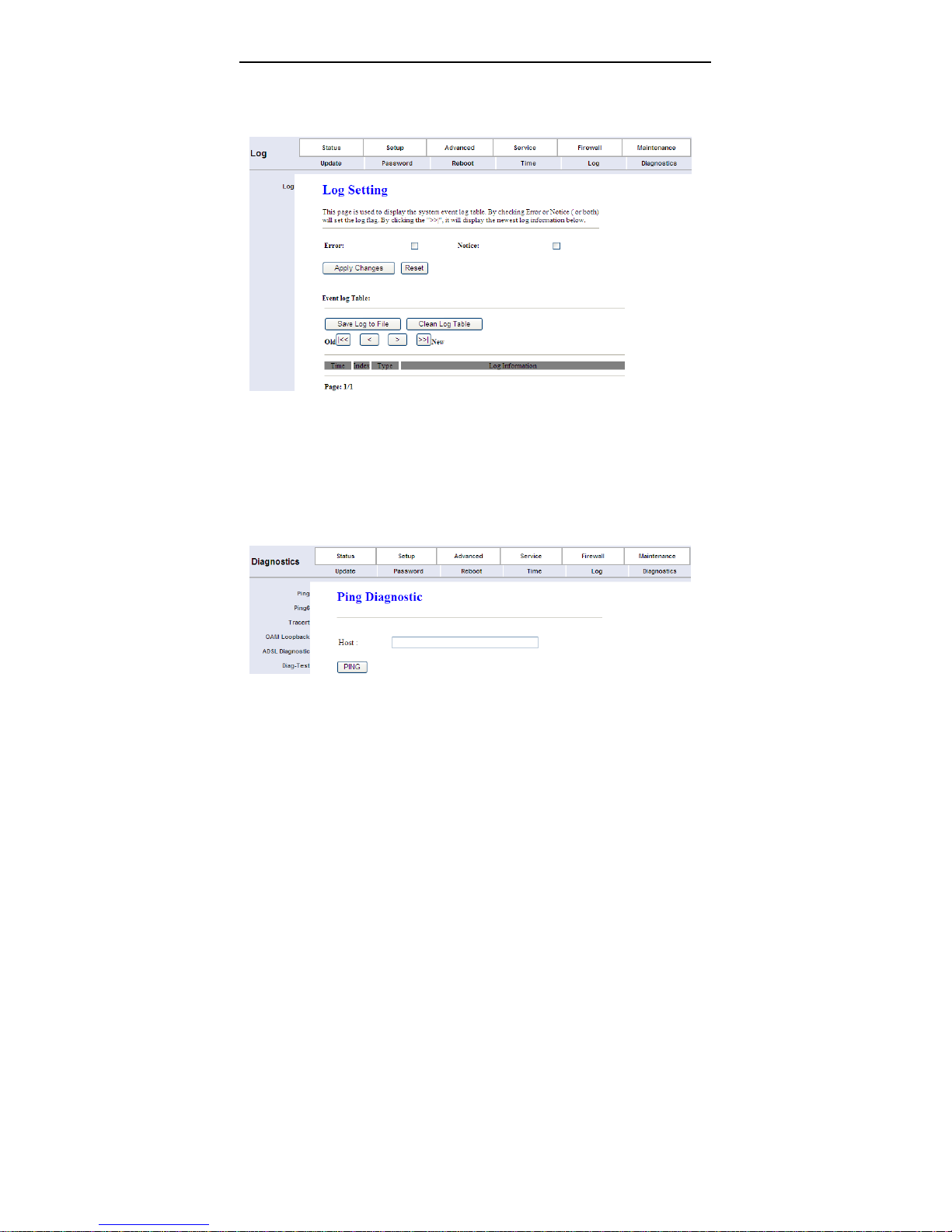
3.8.5 Log
Choose Maintenance > Log, the page shown in the following figure appears. In
this page, you can enable or disable system log function and view the system log.
3.8.6 Diagnostics
Choose Maintenance > Diagnostics, the page shown in the following page
appears. The page that is displayed contains Ping, Ping 6, Tracert, OAM
Loopback, ADSL Diagnostic and Diag-test. Sel ect the option that you want to
run diagnostics.
87
Page 92

4 Q&A
Question Answer
Why are all the
indicators off?
Why is the LAN
indicator not on?
Why is the DSL
indicator not on?
Why does the
Internet access fail
when the DSL
indicator is on?
Why does the web
configuration page
of the device fail to
be accessed?
How to restore the
default configuration
after incorrect
configuration?
User Manual
Check the connection between the power adapter
and the power socket.
Check whether the power switch is turned on.
Check the following:
The connection between the device and the PC,
the hub, or the switch.
The running status of the computer, hub, or switch.
Check the connection between the DSL interface of the
device and the socket.
Ensure that the following information is entered
correctly:
VPI and VCI
User name and password
Choose Start > Run from the desktop. Enter Ping
192.168.1.1 (the default IP address of the device) in the
DOS window.
If the web configuration page still cannot be accessed,
check the following configuration:
The type of the network cable
The connection between the device and the
computer
The TCP/IP pro perties of the network card of the
computer
Keep the device powered on and press the Reset
button for 3 seconds. Then, the device automatically
reboots and is restored to the factory default
configuration.
The default configurations of the device are as follows:
IP address: 192.168.1.1
Subnet mask: 255.255.255.0.
The user name and password of super user are
88
Page 93

User Manual
Question Answer
tmadmin and tmadmin espectively.
The user name and password of common user are
tmuser and tmuser espectively.
89
 Loading...