

Page 1
Table of Contents
D-Link DSL-2542B User Manual
1
Page 2

Table of Contents
D-Link DSL-2542B User Manual
2
Table of Contents
PACKAGE CONTENTS .......................................................................................... 3
SYSTEM REQUIREMENTS ..................................................................................... 3
FEATURES .......................................................................................................... 4
HARDWARE OVERVIEW........................................................................................ 5
Connections ................................................................................................. 5
LEDs............................................................................................................. 6
INSTALLATION .................................................................................................... 7
BEFORE YOU BEGIN............................................................................................ 7
INSTALLATION NOTES .......................................................................................... 8
DEVICE INSTALLATION ....................................................................................... 14
Power on Router ........................................................................................ 14
Factory Reset Button.................................................................................. 15
Network Connections ................................................................................. 16
CONFIGURATION.............................................................................................. 17
WEB-BASED CONFIGURATION UTILITY ................................................................ 17
QUICK SETUP ................................................................................................... 18
DEVICE INFO ..................................................................................................... 40
SUMMARY......................................................................................................... 41
WAN................................................................................................................ 41
STATI STI CS ....................................................................................................... 42
ROUTE ............................................................................................................. 44
ARP ................................................................................................................ 44
DHCP.............................................................................................................. 44
ADVANCED SETUP........................................................................................... 45
WAN................................................................................................................ 45
LAN................................................................................................................. 47
NAT................................................................................................................. 48
Virtual Servers............................................................................................ 48
Port Triggering............................................................................................ 50
DMZ Host ................................................................................................... 52
SECURITY......................................................................................................... 52
IP Filtering .................................................................................................. 52
MAC Filtering.............................................................................................. 55
QUALITY OF SERVICE ........................................................................................ 57
Queue Config.............................................................................................. 57
QoS Classification ...................................................................................... 58
ROUTING .......................................................................................................... 60
Default Gateway ......................................................................................... 60
Static Route ................................................................................................60
RIP..............................................................................................................61
DNS................................................................................................................. 62
DNS Server................................................................................................. 62
Dynamic DNS .............................................................................................62
DSL .................................................................................................................64
PORT MAPPING ................................................................................................. 66
DIAGNOSTICS ................................................................................................... 68
MANAGEMENT ..................................................................................................69
SETTINGS ......................................................................................................... 69
SYSTEM LOG..................................................................................................... 71
TR-069 CLIENT ................................................................................................ 72
INTERNET TIME.................................................................................................. 73
ACCESS CONTROL ............................................................................................ 74
UPDATE SOFTWARE........................................................................................... 75
SAVE /REBOOT................................................................................................... 76
TROUBLESHOOTING........................................................................................ 77
NETWORKING BASICS..................................................................................... 79
CHECK YOUR IP ADDRESS................................................................................. 79
STATI CAL LY ASSIGNING AN IP ADDRESS.............................................................. 80
TECHNICAL SPECIFICATIONS......................................................................... 81
Page 3
Section 1 - Product Overview
D-Link DSL-2542B User Manual
3
Package Contents
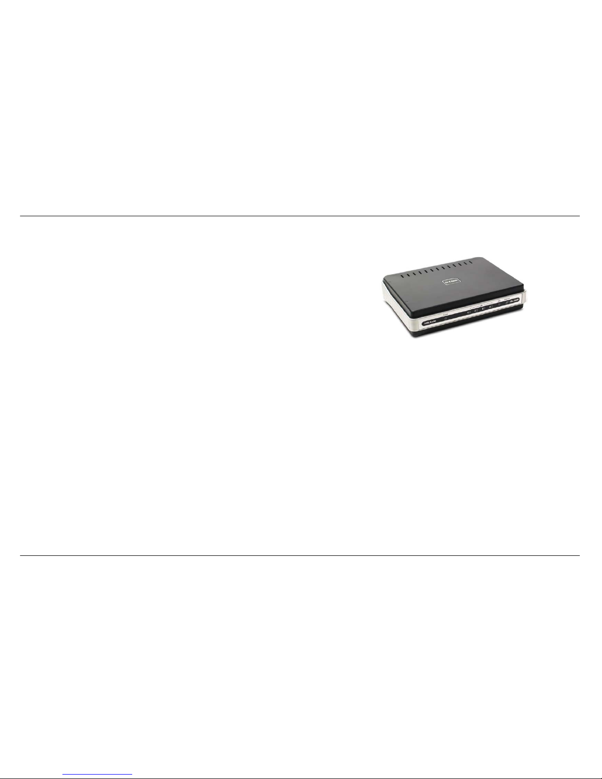
• DSL-2542B ADSL Router
• Power Adapter
• CD-ROM with User Manual
• One twisted-pair telephone cable used for ADSL connection
• One straight-through Ethernet cable
• One Quick Installation Guide
Note: Using a power supply with a different voltage rating than the one included
with the DSL-2542B will cause damage and void the warranty for this product.
System Requirements
• ADSL Internet service
• Computer with:
• 200MHz Processor
• 64MB Memory
• CD-ROM Drive
• Ethernet Adapter with TCP/IP Protocol Installed
• Internet Explorer v6 or later, FireFox v1.5
• Computer with Windows 2000, Windows XP, or Windows Vista
• D-Link Click'n Connect Utility
Page 4

Section 1 - Product Overview
D-Link DSL-2542B User Manual
4
11
Features
• PPP (Point-to-Point Protocol) Security – The DSL-2542B ADSL Router supports PAP (Password Authentication Protocol) and CHAP
(Challenge Handshake Authentication Protocol) for PPP connections. The Router also supports MSCHAP.
• DHCP Support – Dynamic Host Configuration Protocol automatically and dynamically assigns all LAN IP settings to each host on your
network. This eliminates the need to reconfigure every host whenever changes in the network topology occur.
• Network Address Translation (NAT) – For small office environments, the DSL-2542B allows multiple users on the LAN to access the
Internet concurrently through a single Internet account. This provides Internet access to everyone in the office for the price of a single user.
NAT improves network security in effect by hiding the private network behind one global and visible IP address. NAT address mapping can
also be used to link two IP domains via a LAN-to-LAN connection.
• TCP/IP (Transmission Control Protocol/Internet Protocol) – The DSL-2542B supports the TCP/IP protocol, the language used for the
Internet. It is compatible with access servers manufactured by major vendors.
• RIP-1/RIP-2 – The DSL-2542B supports both RIP-1 and RIP-2 exchanges with other routers. Using both versions allows the Router to
communicate with all RIP enabled devices.
• Static Routing – This allows you to select a data path to a particular network destination that will remain in the routing table and never “age
out”. Create a static route if you wish to define a specific route that will always be used for data traffic from your LAN to a specific destination
within your LAN (for example to another router or a server) or to a specific destination outside your network (to an ISP defined default
gateway for instance).
• Default Routing – This allows you to choose a default path for incoming data packets for which the destination address is unknown. This is
particularly useful when/if the Router functions as the sole connection to the Internet.
• ATM (Asynchronous Transfer Mode) – The DSL-2542B supports Bridged Ethernet over ATM (RFC1483), IP over ATM (RFC1577), and
PPP over ATM (RFC 2364).
• Precise ATM Traffic Shaping – Traffic shaping is a method of controlling the flow rate of ATM data cells. This function helps to establish the
Quality of Service for ATM data transfer.
• G.hs (Auto-handshake) – This allows the Router to automatically choose either the G.lite or G.dmt ADSL connection standards.
• High Performance – Very high rates of data transfer are possible with the Router. Up to 8 Mbps downstream bit rate using the G.dmt
standard.
• Telnet Connection – Telnet enables a network manager to access the Router’s management software remotely.
• Easy Installation – The DSL-2542B uses a web-based graphical user interface program for convenient management access and easy set
up. Any common web browser software can be used to manage the Router.
Page 5
Section 1 - Product Overview
D-Link DSL-2542B User Manual
5
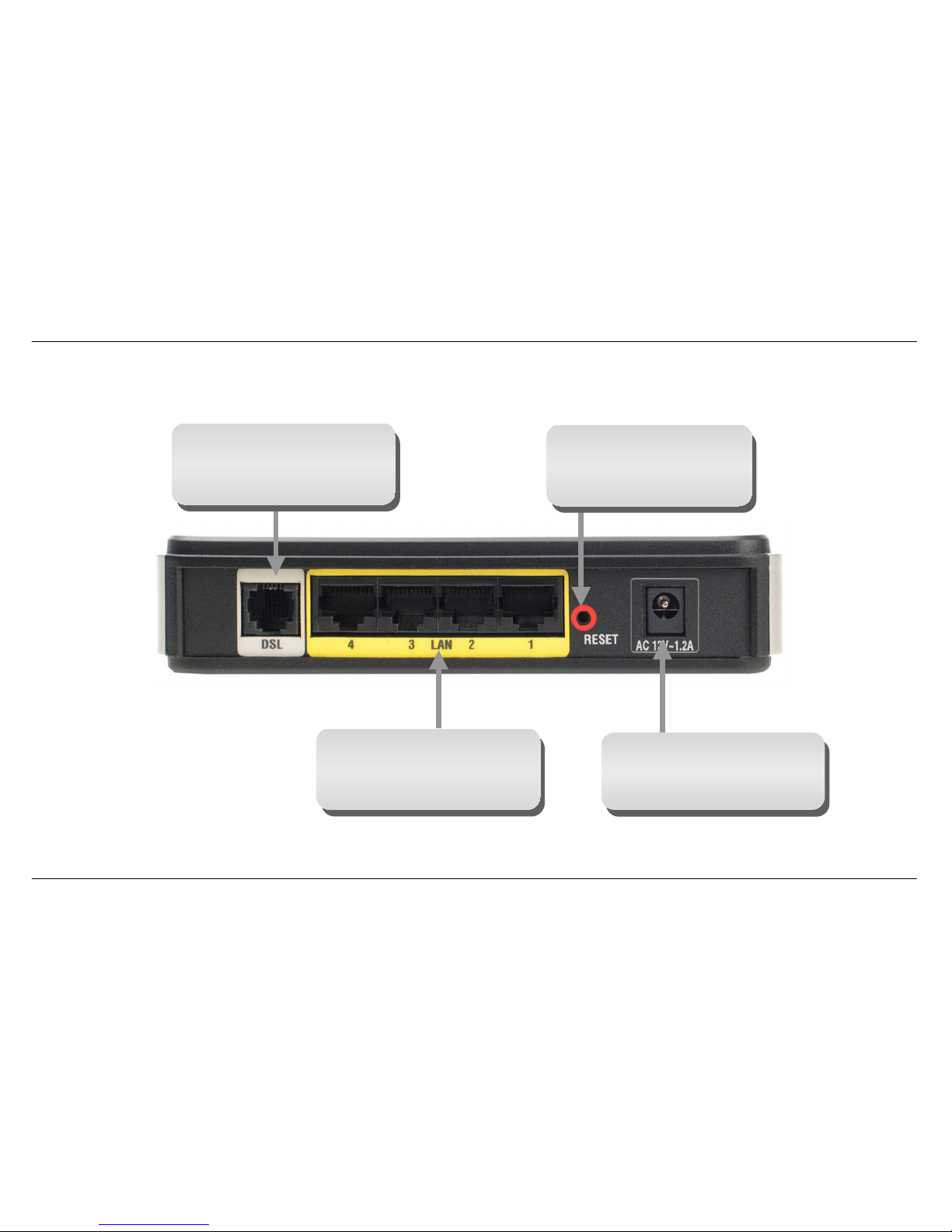
Hardware Overview
Connections
Power Insert
Use the adapter shipped with the
Router to connect to power
source
Ethernet Port
Use the Ethernet port to connect
the Router to a computer or an
Ethernet LAN
ADSL Port
Use the ADSL cable to connect
to the your telephone line (RJ-11
port)
Reset Button
To manually reset, depress
button with the power on for a
t
least seven seconds
Page 6
Section 1 - Product Overview
D-Link DSL-2542B User Manual
6
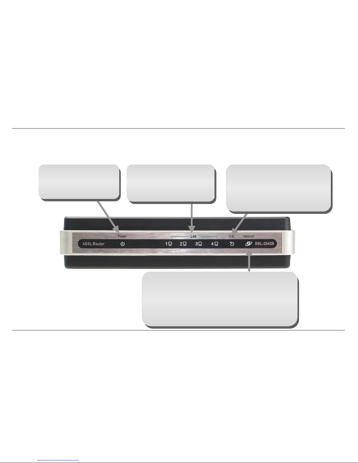
Hardware Overview
LEDs
Power
A steady green light indicates
the unit is powered on. When
the device is powered off this
remains dark.
DSL
A steady green light indicates a valid
ADSL connection. This will light after the
ADSL negotiation process has been
settled. A blinking green light indicates
activity on the WAN (ADSL) interface.
LAN
A
solid green light indicates a valid
link on startup. This light will blink
when there is activity currently
passing through the Ethernet port.
Internet
A solid green light indicates the WAN IP address from IPCP or
DHCP and DSL is up or a static IP address is configured and
PPP negotiation has been successfully completed. If the
indicator blinks green, this means the Router is active. If the
Router power is off, this remains dark. A solid red light indicates
there is no DHCP response, no PPPoE response, PPPoE
authentication has failed, and/or there is no IP.
Page 7

Section 2 – Installation
D-Link DSL-2542B User Manual
7
Installation
This section will walk you through the installation process. Placement of the Router is very important. Do not place the Router in an enclosed area
such as a closet, cabinet or in the attic or garage.
Before You Begin
Please read and make sure you understand all the prerequisites for proper installation of your new Router. Have all the necessary information and
equipment on hand before beginning the installation.
Page 8

Section 2 – Installation
D-Link DSL-2542B User Manual
8
Installation Notes
In order to establish a connection to the Internet it will be necessary to provide information to the Router that will be stored in its memory. For some
users, only their account information (Username and Password) is required. For others, various parameters that control and define the Internet
connection will be required. You can print out the two pages below and use the tables to list this information. This way you have a hard copy of all
the information needed to setup the Router. If it is necessary to reconfigure the device, all the necessary information can be easily accessed. Be
sure to keep this information safe and private.
Low Pass Filters
Since ADSL and telephone services share the same copper wiring to carry their respective signals, a filtering mechanism may be necessary to
avoid mutual interference. A low pass filter device can be installed for each telephone that shares the line with the ADSL line. These filters are easy
to install passive devices that connect to the ADSL device and/or telephone using a standard telephone cable. Ask your service provider for more
information about the use of low pass filters with your installation.
Operating Systems
The DSL-2542B uses an HTML-based web interface for setup and management. The web configuration manager may be accessed using any
operating system capable of running web browser software, including Windows 98 SE, Windows ME, Windows 2000, Windows XP, and Windows
Vista.
Web Browser
Any common web browser can be used to configure the Router using the web configuration management software. The program is designed to
work best with more recently released browsers such as Opera, Microsoft Internet Explorer® version 6.0, Netscape Navigator® version 6.2.3, or
later versions. The web browser must have JavaScript enabled. JavaScript is enabled by default on many browsers. Make sure JavaScript has not
been disabled by other software (such as virus protection or web user security packages) that may be running on your computer.
Ethernet Port (NIC Adapter)
Any computer that uses the Router must be able to connect to it through the Ethernet port on the Router. This connection is an Ethernet connection
and therefore requires that your computer be equipped with an Ethernet port as well. Most notebook computers are now sold with an Ethernet port
already installed. Likewise, most fully assembled desktop computers come with an Ethernet NIC adapter as standard. If your computer does not
have an Ethernet port, you must install an Ethernet NIC adapter before you can use the Router. If you must install an adapter, follow the installation
instructions that come with the Ethernet NIC adapter.
Page 9

Section 2 – Installation
D-Link DSL-2542B User Manual
9
Additional Software
It may be necessary to install software on your computer that enables the computer to access the Internet. Additional software must be installed if
you are using the device as a simple bridge. For a bridged connection, the information needed to make and maintain the Internet connection is
stored on another computer or gateway device, not in the Router itself.
If your ADSL service is delivered through a PPPoE or PPPoA connection, the information needed to establish and maintain the Internet connection
can be stored in the Router. In this case, it is not necessary to install software on your computer. It may however be necessary to change some
settings in the device, including account information used to identify and verify the connection.
All connections to the Internet require a unique global IP address. For bridged connections, the global IP settings must reside in a TCP/IP enabled
device on the LAN side of the bridge, such as a PC, a server, a gateway device, such as a router, or similar firewall hardware. The IP address can
be assigned in a number of ways. Your network service provider will give you instructions about any additional connection software or NIC
configuration that may be required.
Page 10

Section 2 – Installation
D-Link DSL-2542B User Manual
10
Information you will need from your ADSL service
provider
Username
This is the Username used to log on to your ADSL service provider’s network. Your ADSL service provider uses this to identify your account.
Password
This is the Password used, in conjunction with the Username above, to log on to your ADSL service provider’s network. This is used to verify the
identity of your account.
WAN Setting / Connection Type
These settings describe the method your ADSL service provider uses to transport data between the Internet and your computer. Most users will use
the default settings. You may need to specify one of the following WAN Setting and Connection Type configurations (Connection Type settings listed
in parenthesis):
• PPPoE/PPPoA (PPPoE LLC, PPPoA LLC or PPPoA VC-Mux)
• Bridge Mode (1483 Bridged IP LLC or 1483 Bridged IP VC Mux)
• IPoA/MER (Static IP Address) (Bridged IP LLC, 1483 Bridged IP VC Mux, 1483 Routed IP LLC, 1483 Routed IP VC-Mux or IPoA)
• MER (Dynamic IP Address) (1483 Bridged IP LLC or 1483 Bridged IP VC-Mux)
Modulation Type
ADSL uses various standardized modulation techniques to transmit data over the allotted signal frequencies. Some users may need to change the
type of modulation used for their service. The default DSL modulation (ADSL2+ Multi-Mode) used for the Router automatically detects all types of
ADSL, ADSL2 and ADSL2+ modulation.
Security Protocol
This is the method your ADSL service provider will use to verify your Username and Password when you log on to their network. Your Router
supports the PAP and CHAP protocols.
VPI
Most users will not be required to change this setting. The Virtual Path Identifier (VPI) is used in conjunction with the Virtual Channel Identifier (VCI)
to identify the data path between your ADSL service provider’s network and your computer. If you are setting up the Router for multiple virtual
connections, you will need to configure the VPI and VCI as instructed by your ADSL service provider for the additional connections. This setting can
be changed in the WAN Settings window of the web management interface.
Page 11

Section 2 – Installation
D-Link DSL-2542B User Manual
11
VCI
Most users will not be required to change this setting. The Virtual Channel Identifier (VCI) is used in conjunction with the VPI to identify the data path
between your ADSL service provider’s network and your computer. If you are setting up the Router for multiple virtual connections, you will need to
configure the VPI and VCI as instructed by your ADSL service provider for the additional connections. This setting can be changed in the WAN
Setup window of the web management interface.
Page 12

Section 2 – Installation
D-Link DSL-2542B User Manual
12
Information you will need about DSL-2542B
Username
This is the Username needed to access the Router’s management interface. When you attempt to connect to the device through a web browser you
will be prompted to enter this Username. The default Username for the Router is “admin.” The user cannot change this.
Password
This is the Password you will be prompted to enter when you access the Router’s management interface. The default Password is “admin.” The
user may change this.
LAN IP addresses for the DSL-2542B
This is the IP address you will enter into the Address field of your web browser to access the Router’s configuration graphical user interface (GUI)
using a web browser. The default IP address is 192.168.1.1. This may be changed to suit any IP address scheme the user desires. This address will
be the base IP address used for DHCP service on the LAN when DHCP is enabled.
LAN Subnet Mask for the DSL-2542B
This is the subnet mask used by the DSL-2542B and will be used throughout your LAN. The default subnet mask is 255.255.255.0. This can be
changed later.
Page 13

Section 2 – Installation
D-Link DSL-2542B User Manual
13
Information you will need about your LAN or computer:
Ethernet NIC
If your computer has an Ethernet NIC, you can connect the DSL-2542B to the Ethernet port using an Ethernet cable. You can also use the Ethernet
ports on the DSL-2542B to connect to other computers or Ethernet devices.
DHCP Client status
Your DSL-2542B ADSL Router is configured, by default, to be a DHCP server. This means that it can assign an IP address, subnet mask and a
default gateway address to computers on your LAN. The default range of IP addresses the DSL-2542B will assign are from 192.168.1.2 to
192.168.1.254. Your computer (or computers) needs to be configured to obtain an IP address automatically (that is, they need to be configured as
DHCP clients.)
It is recommended that you collect and record this information here, or in some other secure place, in case you have to re-configure your ADSL
connection in the future.
Once you have the above information, you are ready to setup and configure your DSL-2542B ADSL Router.
Page 14

Section 2 – Installation
D-Link DSL-2542B User Manual
14
Device Installation
The DSL-2542B connects two separate physical interfaces, an ADSL (WAN) and an Ethernet (LAN) interface. Place the Router in a location where
it can be connected to the various devices as well as to a power source. The Router should not be located where it will be exposed to moisture or
excessive heat. Make sure the cables and power cord are placed safely out of the way so they do not create a tripping hazard. As with any electrical
appliance, observe common sense safety procedures.
The Router can be placed on a shelf or desktop, ideally you should be able to see the LED indicators on the front if you need to view them for
troubleshooting.
Power on Router
The Router must be used with the power adapter included with the device.
1. Insert the AC Power Adapter cord into the power receptacle located on the rear panel of the Router and plug the adapter into a suitable nearby
power source. You should see the Power LED indicator light up and remain lit. The Status LED should light solid green and begin to blink after a
few seconds.
2. If the Ethernet port is connected to a working device, check the Ethernet Link/Act LED indicators to make sure the connection is valid. The
Router will attempt to establish the ADSL connection, if the ADSL line is connected and the Router is properly configured this should light up
after several seconds. If this is the first time you have installed the device, some settings may need to be changed before the Router can
establish a connection.
Page 15

Section 2 – Installation
D-Link DSL-2542B User Manual
15
Factory Reset Button
The Router may be reset to the original factory default settings by using a ballpoint or paperclip to gently push down the reset button in the following
sequence:
1. Press and hold the reset button while the device is powered off.
2. Turn on the power.
3. Wait for 5~8 seconds and then release the reset button.
Remember that this will wipe out any settings stored in flash memory including user account information and LAN IP settings. The device settings
will be restored to the factory default IP address 192.168.1.1 and the subnet mask 255.255.255.0, the default management Username is “admin”
and the default Password is “admin.”
Page 16

Section 2 – Installation
D-Link DSL-2542B User Manual
16
Network Connections
Connect ADSL Line
Use the ADSL cable included with the Router to connect it to a telephone wall socket or receptacle. Plug one end of the cable into the ADSL port
(RJ-11 receptacle) on the rear panel of the Router and insert the other end into the RJ-11 wall socket. If you are using a low pass filter device, follow
the instructions included with the device or the instructions given to you by your service provider. The ADSL connection represents the WAN
interface, the connection to the Internet. It is the physical link to the service provider’s network backbone and ultimately to the Internet.
Connect Router to Ethernet
The Router may be connected to a single computer or Ethernet device through the 10BASE-TX Ethernet port on the rear panel. Any connection to
an Ethernet concentrating device such as a switch or hub must operate at a speed of 10/100 Mbps only. When connecting the Router to any
Ethernet device that is capable of operating at speeds higher than 10Mbps, be sure that the device has auto-negotiation (NWay) enabled for the
connecting port. Use standard twisted-pair cabling with RJ-45 connectors. The RJ-45 port on the Router is a crossed port (MDI-X). Follow standard
Ethernet guidelines when deciding what type of cable to use to make this connection. When connecting the Router directly to a PC or server use a
normal straight-through cable. You should use a crossed cable when connecting the Router to a normal (MDI-X) port on a switch or hub. Use a
normal straight-through cable when connecting it to an uplink (MDI-II) port on a hub or switch. The rules governing Ethernet cable lengths apply to
the LAN to Router connection. Be sure that the cable connecting the LAN to the Router does not exceed 100 meters.
Hub or Switch to Router Connection
Connect the Router to an uplink port (MDI-II) on an Ethernet hub or switch with a straight-through cable. If you wish to reserve the uplink port on the
switch or hub for another device, connect to any of the other MDI-X ports (1x, 2x, etc.) with a crossed cable.
Computer to Router Connection
You can connect the Router directly to a 10/100BASE-TX Ethernet adapter card (NIC) installed in a PC using the Ethernet cable provided.
Page 17
Section 3 – Configuration
D-Link DSL-2542B User Manual
17
Configuration
This section will show you how to configure your new D-Link Router using the web-based configuration utility.
Web-based Configuration Utility
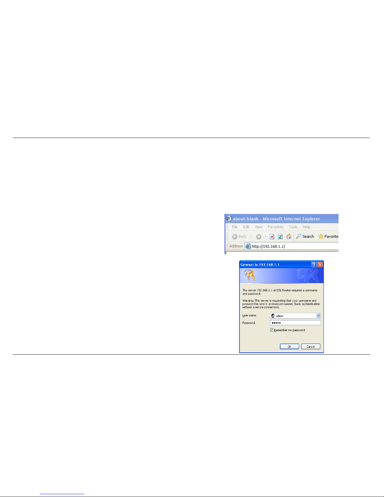
Connect to the Router
To configure the WAN connection used by the Router it is first necessary to communicate with the Router through its management interface, which
is HTML-based and can be accessed using a web browser. The easiest way to make sure your computer has the correct IP settings is to configure
it to use the DHCP server in the Router. The next section describes how to change the IP configuration for a computer running a Windows operating
system to be a DHCP client.
To access the configuration utility, open a web-browser such as Internet
Explorer and enter the IP address of the router (192.168.1.1).
Type “admin” for the User Name and “admin” in the Password field. If
you get a Page Cannot be Displayed error, please refer to the
Troubleshooting section for assistance.
Page 18
Section 3 – Configuration
D-Link DSL-2542B User Manual
18
Quick Setup
This chapter is concerned with using your computer to configure the WAN connection. The following chapter describes the various windows used to
configure and monitor the Router including how to change IP settings and DHCP server setup.
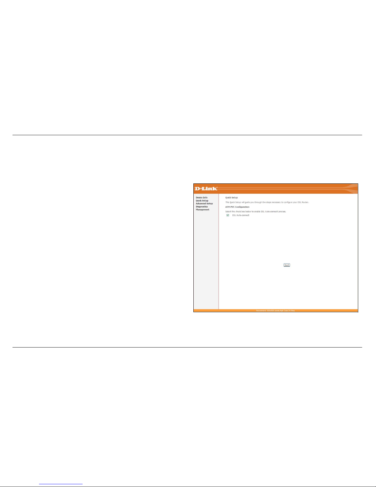
QUICK SETUP
Click the Quick Setup link on the left panel of the opening page to launch
a series of setup windows.
Tick the DSL Auto-connect check box and then click the Next button.
If the ADSL connection is down, deselect the DSL Auto-connect
checkbox and then click the Next button to manually assign VPI and VCI
values.
Page 19
Section 3 – Configuration
D-Link DSL-2542B User Manual
19
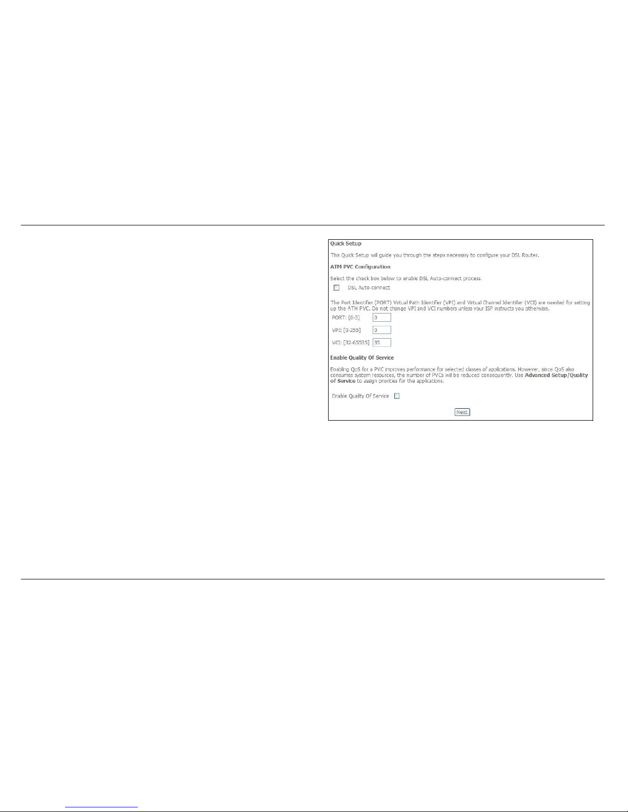
QUICK SETUP
This window allows you to set up ATM PVC configuration. Enter a Port
Identifier, Virtual Path Identifier, and Virtual Channel Identifier. The VPI
and VCI values should be provided by your ISP. This window also allows
you to enable QoS by ticking the Enable Quality of Service check box.
Click the Next button to continue.
Page 20
Section 3 – Configuration
D-Link DSL-2542B User Manual
20
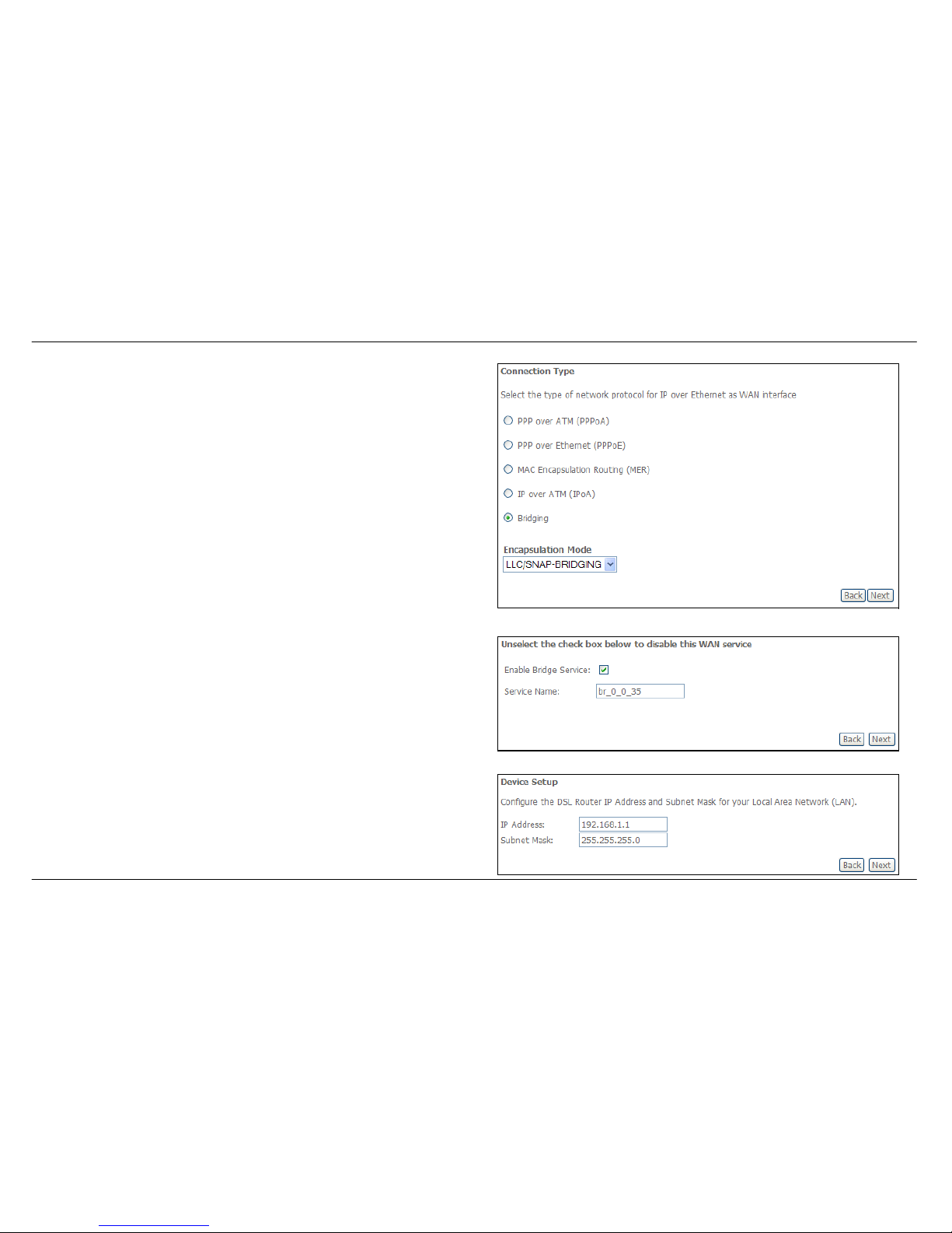
QUICK SETUP – CONNECTION TYPE
This window allows you to select the appropriate connection type. The
choices include PPP over ATM (PPPoA), PPP over Ethernet (PPPoE),
MAC Encapsulation Routing (MER), IP over ATM (IPoA), and Bridging
(default).
This window also allows you to use the drop-down menu to select the
desired Encapsulation Mode. Click the Next button to continue.
QUICK SETUP – BRIDGING
To enable bridging, tick the Enable Bridge Service check box and enter a
Service Name.
To disable WAN service, unselect the check box.
Click the Next button to continue.
QUICK SETUP – BRIDGING
This window allows you to configure the Router IP address and subnet
mask for your LAN. Once you have entered an IP address and subnet
mask, click the Next button to continue.
Page 21
Section 3 – Configuration
D-Link DSL-2542B User Manual
21
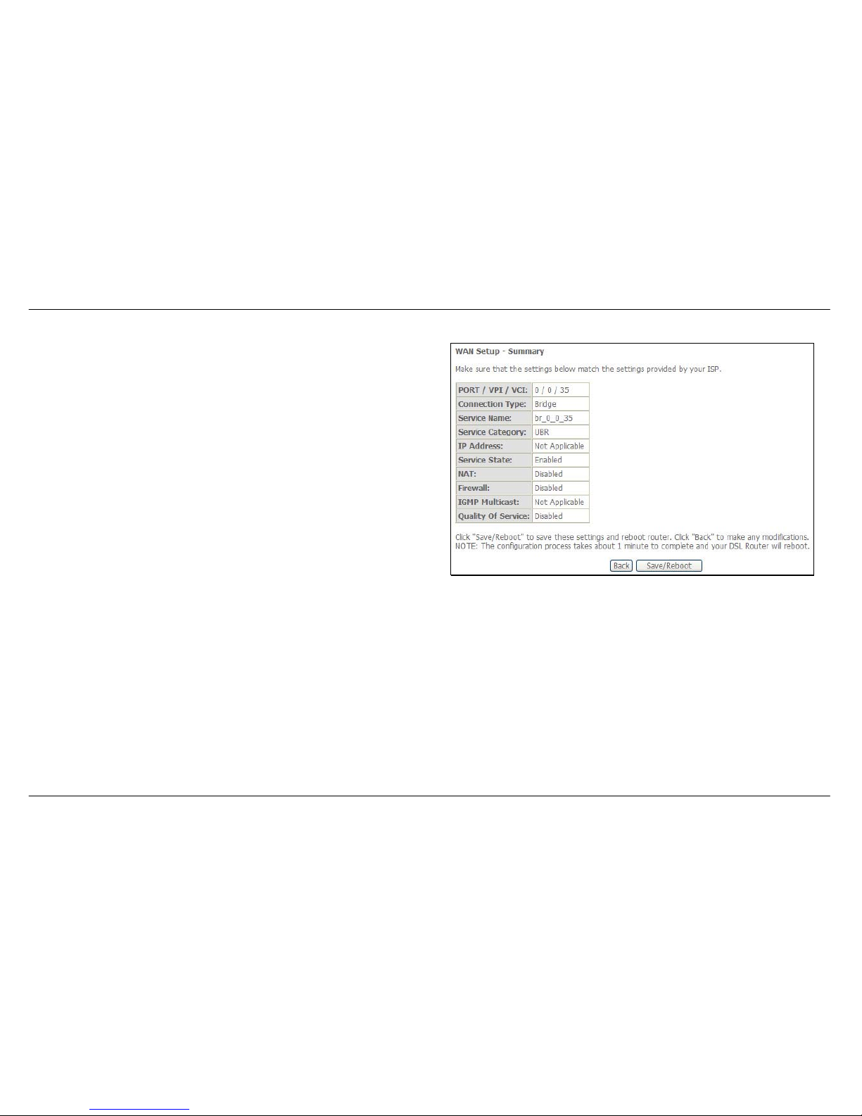
QUICK SETUP – BRIDGING
This summary window allows you to confirm the bridging settings you
have just made. Click the Save/Reboot button to save your new bridging
settings and restart the Router.
Page 22
Section 3 – Configuration
D-Link DSL-2542B User Manual
22
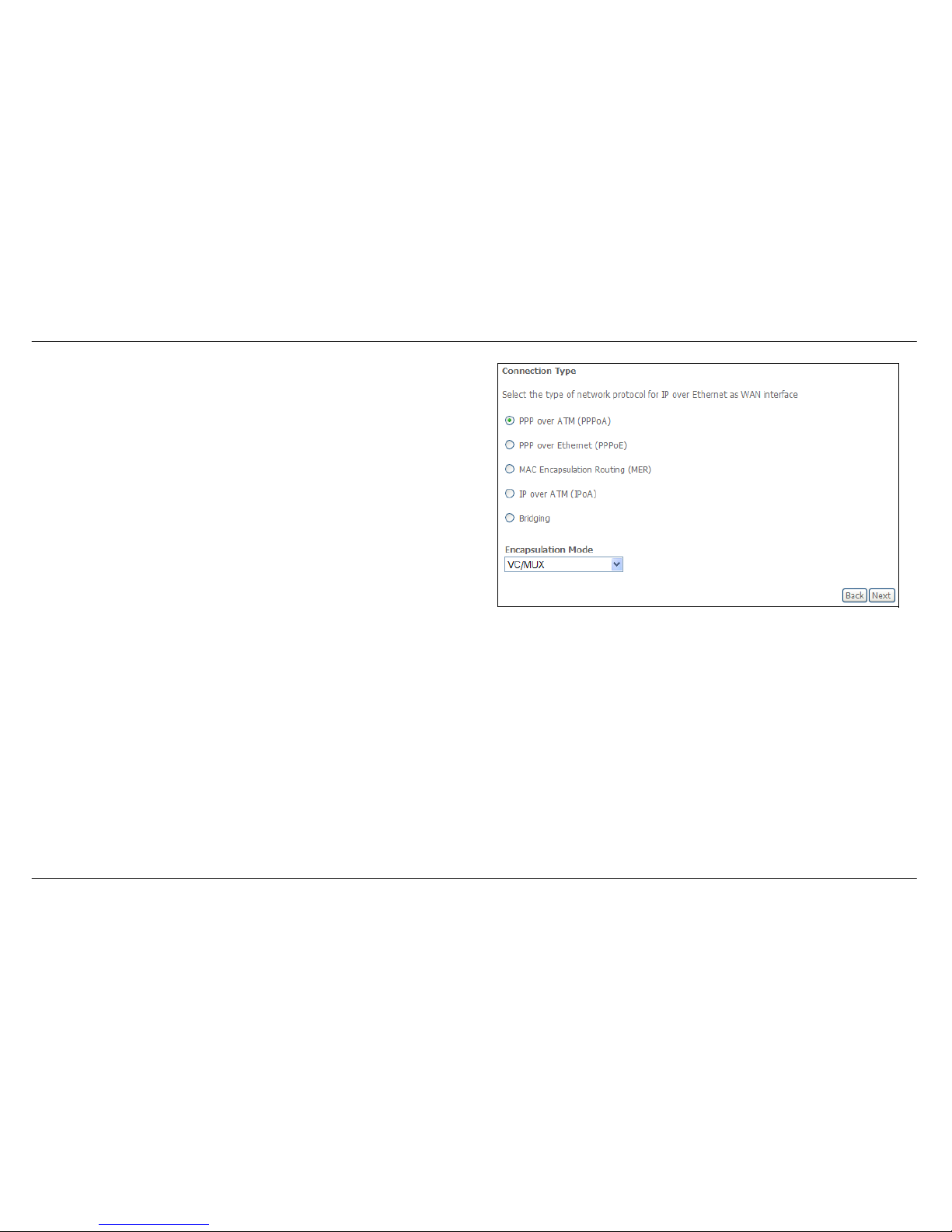
QUICK SETUP – PPPoA
Click the PPP over ATM (PPPoA) radio button on this window. This
window also allows you to use the drop-down menu to select the desired
Encapsulation Mode. Click the Next button to continue.
Page 23
Section 3 – Configuration
D-Link DSL-2542B User Manual
23
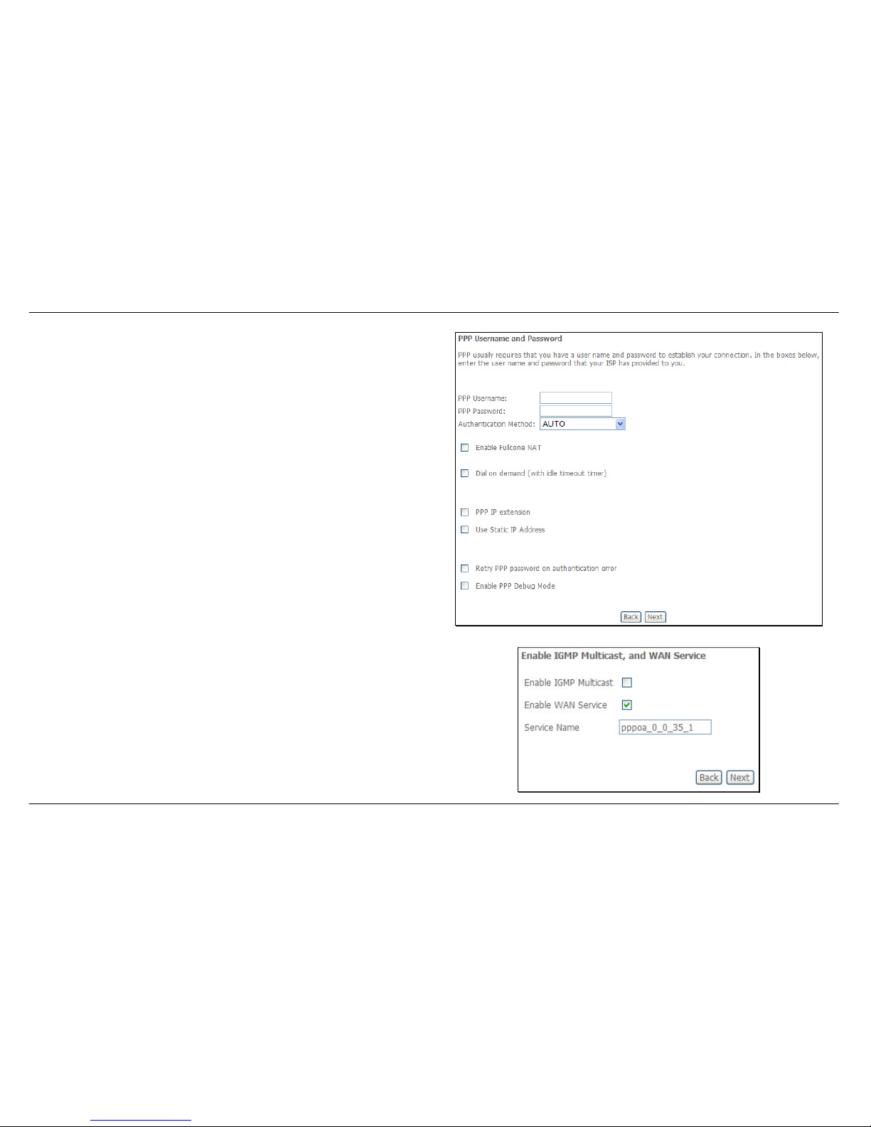
QUICK SETUP – PPPoA
This window allows you to set the username and the password for your
PPP connection. This information is obtained from your ISP. Additional
settings on this window will also depend on your ISP. Click the Next
button to continue.
QUICK SETUP - PPPoA
This window allows you to enable IGMP multicasting and WAN service.
Click the Next button to continue.
Page 24
Section 3 – Configuration
D-Link DSL-2542B User Manual
24
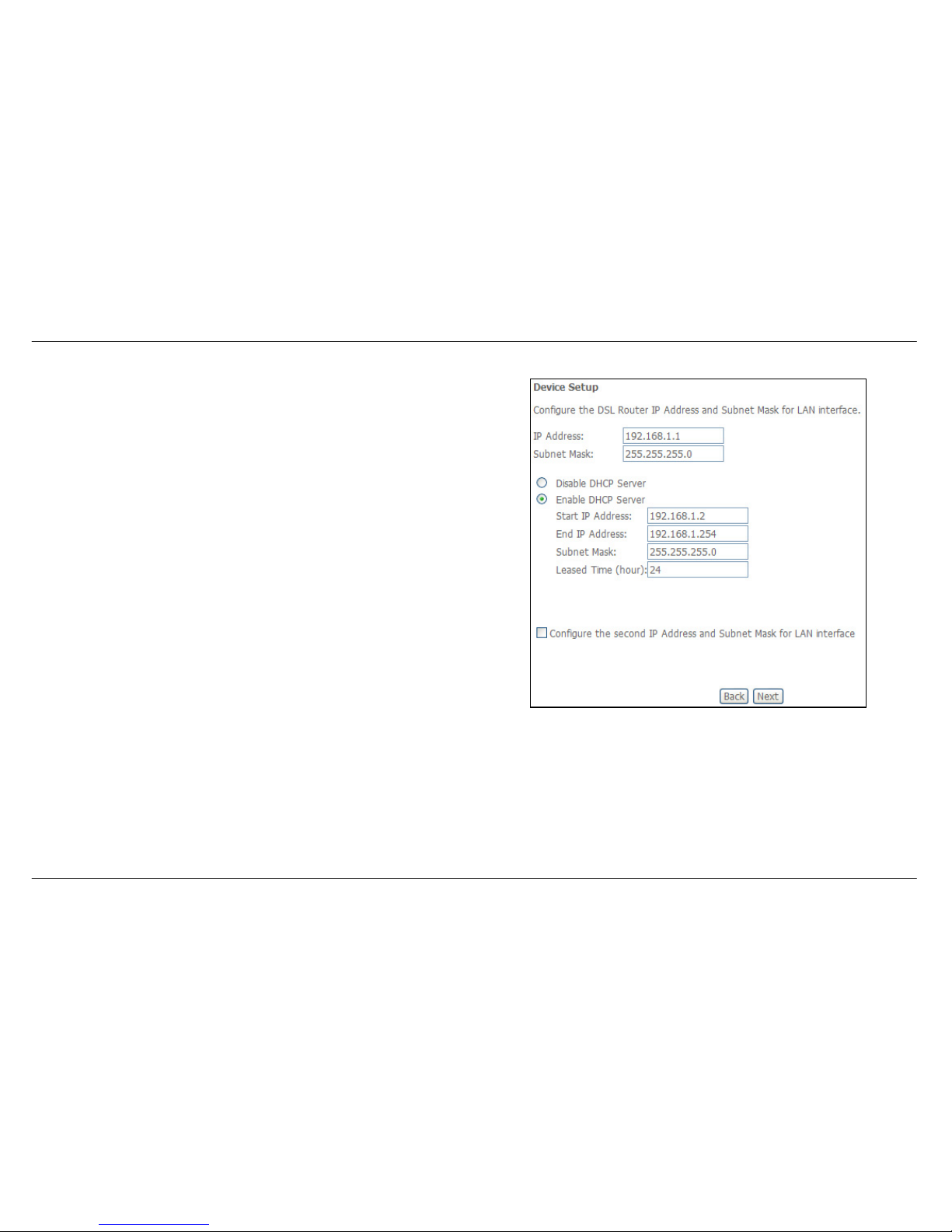
QUICK SETUP - PPPoA
This window allows you to enter an IP address and subnet mask for the
LAN interface. In addition, you can either enable or disable the DHCP
server.
To enable the DHCP server, enter a starting IP address, an ending IP
address, and a subnet mask. You may also choose to change the default
value of the leased time. Click the Next button to continue.
Page 25
Section 3 – Configuration
D-Link DSL-2542B User Manual
25
QUICK SETUP – PPPoA
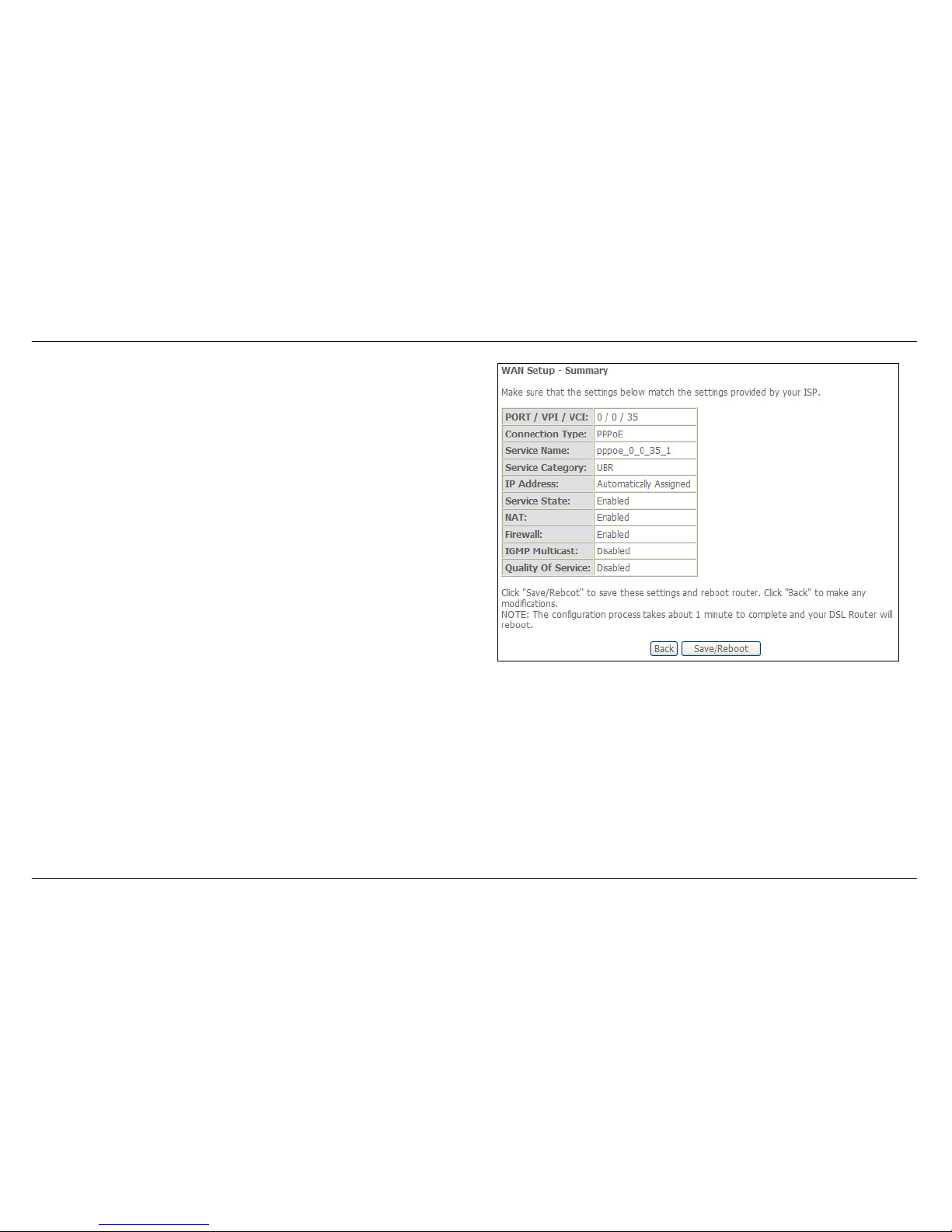
This summary window allows you to confirm the settings you have just
made. Click the Save/Reboot button to save your new PPP over ATM
settings and restart the Router.
Page 26
Section 3 – Configuration
D-Link DSL-2542B User Manual
26
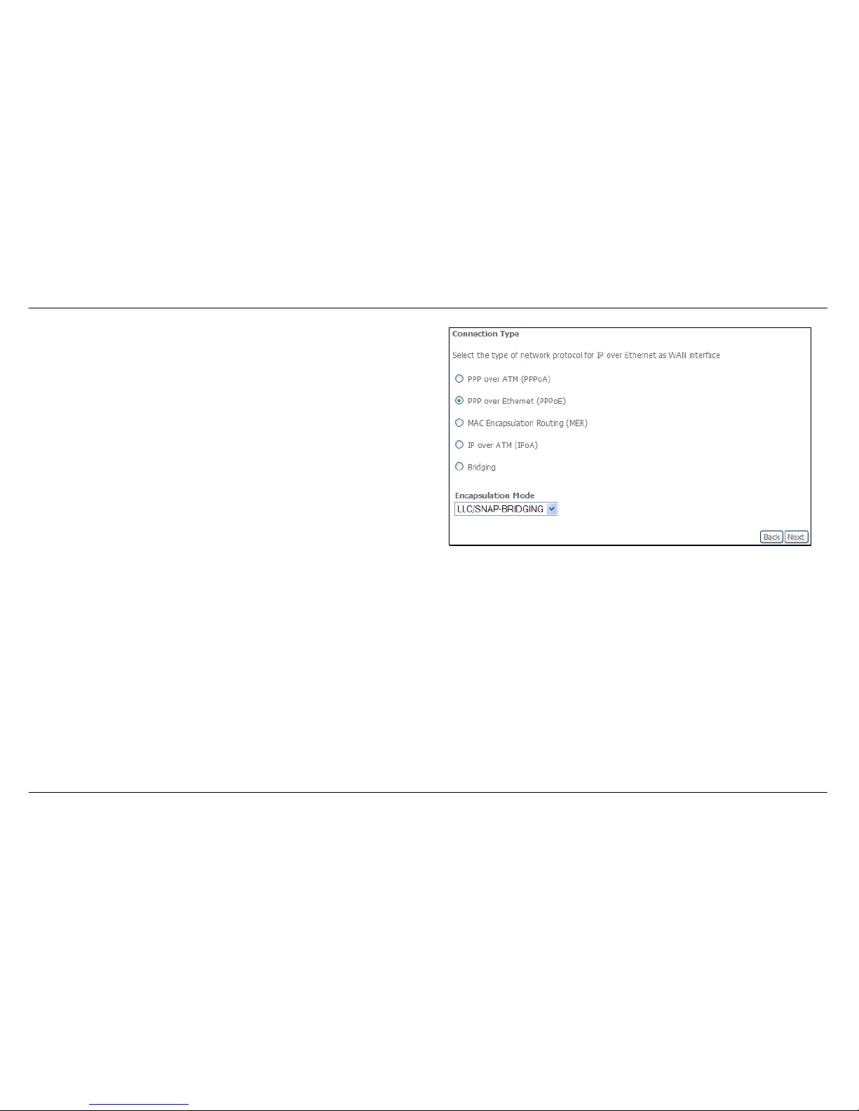
QUICK SETUP – PPPoE
Click the PPP over Ethernet (PPPoE) radio button on this window. This
window also allows you to use the drop-down menu to select the desired
Encapsulation Mode. Click the Next button to continue.
Page 27
Section 3 – Configuration
D-Link DSL-2542B User Manual
27
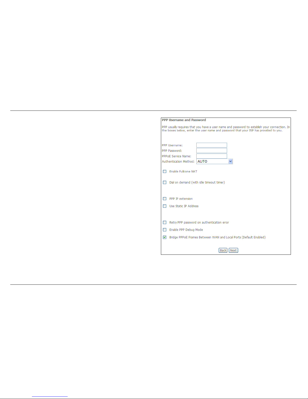
QUICK SETUP – PPPoE
This window allows you to set the username and the password for your
PPP connection. This information is obtained from your ISP. Additional
settings on this window will also depend on your ISP. Click the Next
button to continue.
Page 28
Section 3 – Configuration
D-Link DSL-2542B User Manual
28
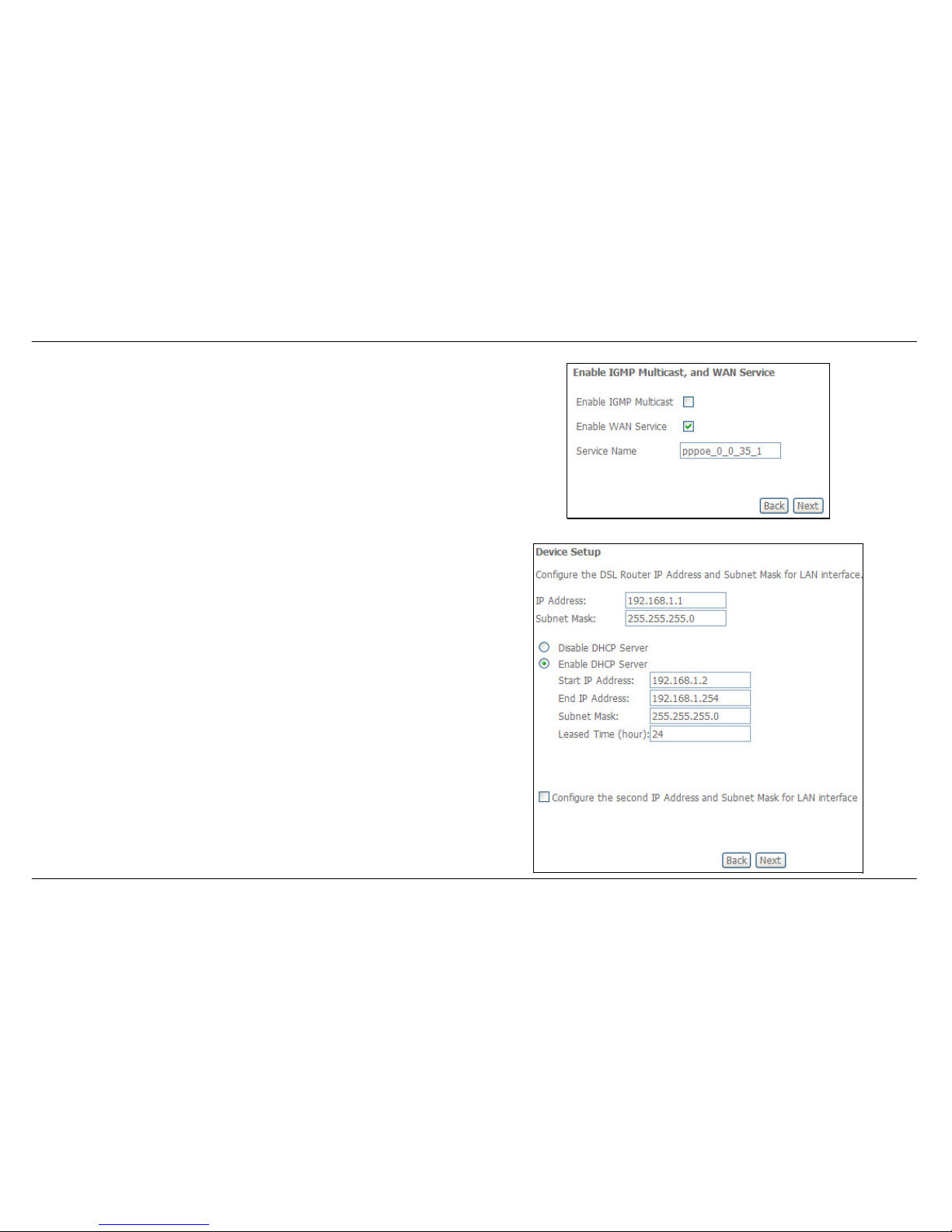
QUICK SETUP – PPPoE
This window allows you to enable IGMP multicasting and WAN service.
Click the Next button to continue.
QUICK SETUP – PPPoE
This window allows you to enter an IP address and subnet mask for the
LAN interface. In addition, you can either enable or disable the DHCP
server.
To enable the DHCP server, enter a starting IP address, an ending IP
address, and a subnet mask. You may also choose to change the default
value of the leased time. Click the Next button to continue.
Page 29
Section 3 – Configuration
D-Link DSL-2542B User Manual
29
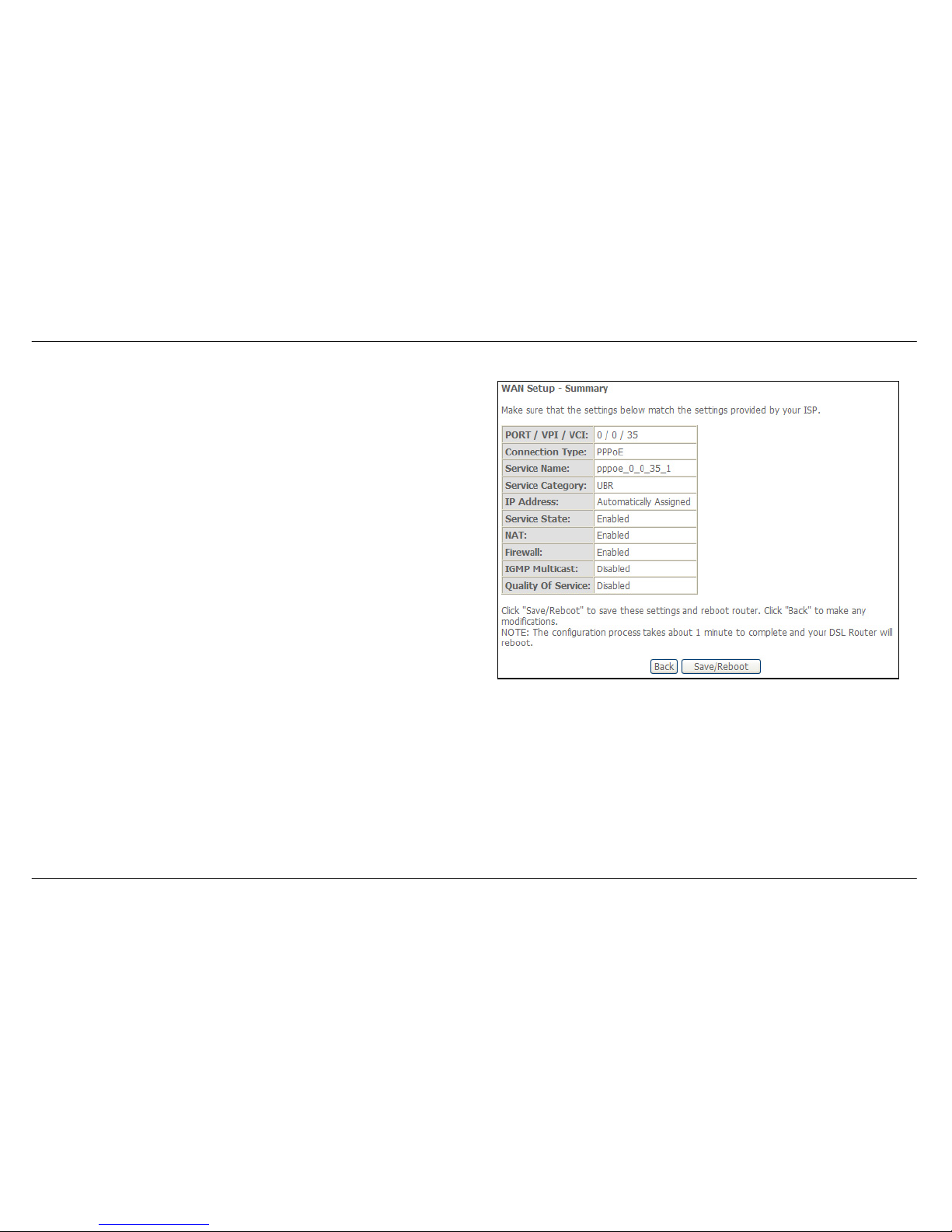
QUICK SETUP – PPPoE
This summary window allows you to confirm the settings you have just
made. Click the Save/Reboot button to save your new PPP over Ethernet
settings and restart the Router.
Page 30
Section 3 – Configuration
D-Link DSL-2542B User Manual
30
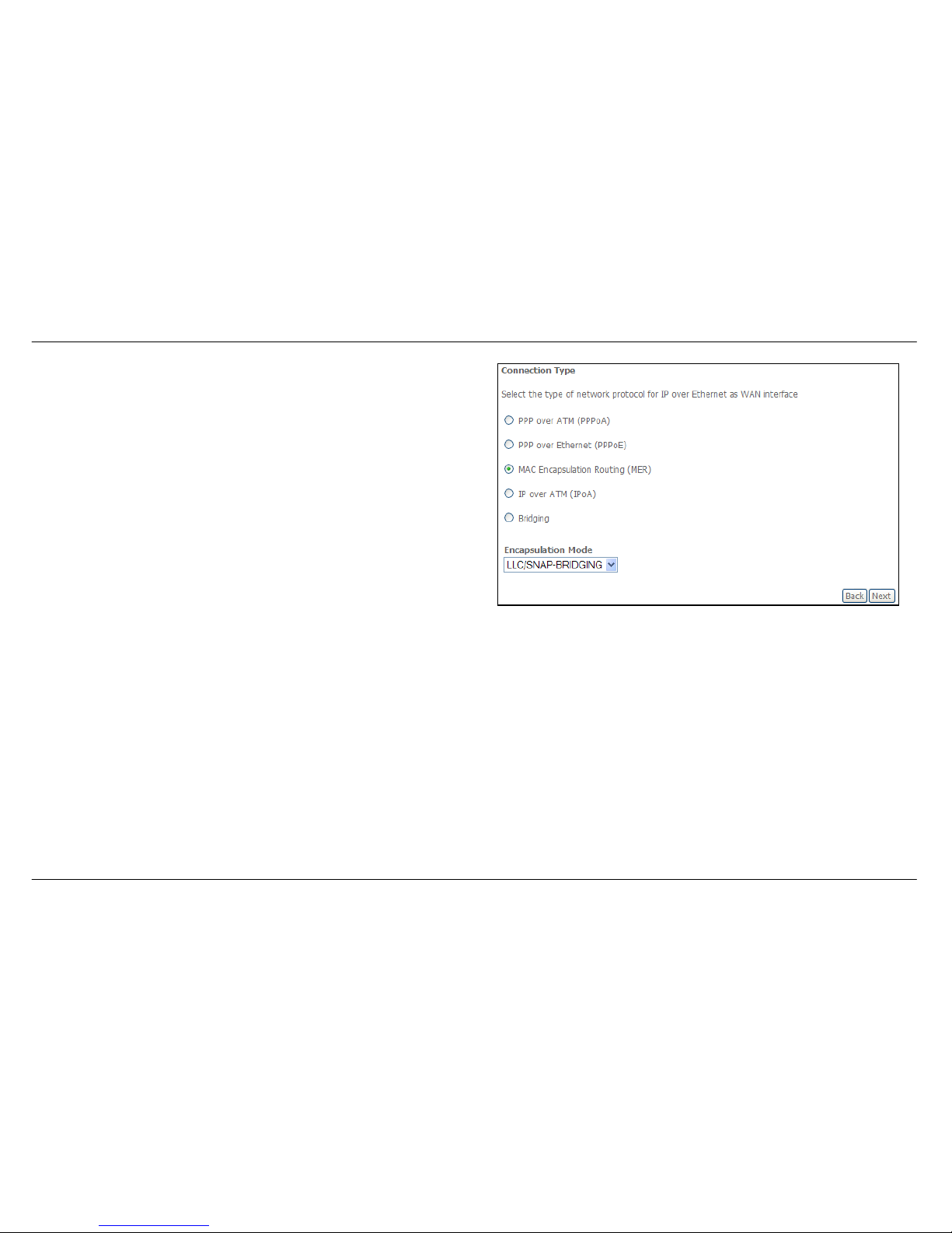
QUICK SETUP – MER
Click the MAC Encapsulation Routing (MER) radio button on this window.
This window also allows you to use the drop-down menu to select the
desired Encapsulation Mode. Click the Next button to continue.
Page 31
Section 3 – Configuration
D-Link DSL-2542B User Manual
31
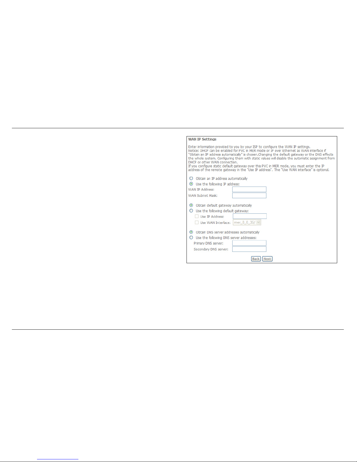
QUICK SETUP – MER
This window allows you to configure the WAN IP settings. This information
is obtained from your ISP. Click the Next button to continue.
Page 32
Section 3 – Configuration
D-Link DSL-2542B User Manual
32
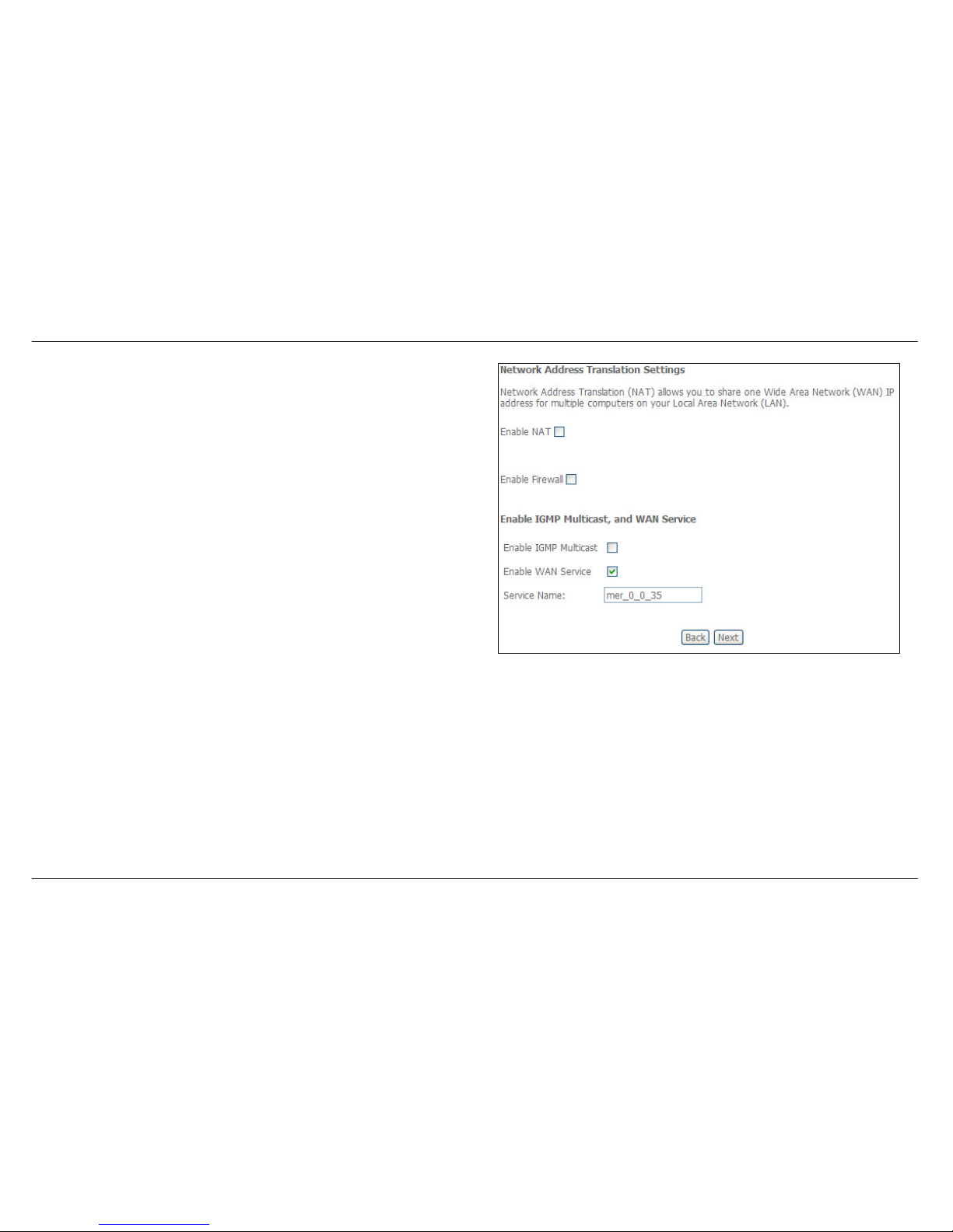
QUICK SETUP – MER
This window allows you to enable or disable Network Address Translation
and a firewall for your Router. In addition, you can enable or disable IGMP
multicasting and WAN service. Click the Next button to continue.
Page 33
Section 3 – Configuration
D-Link DSL-2542B User Manual
33
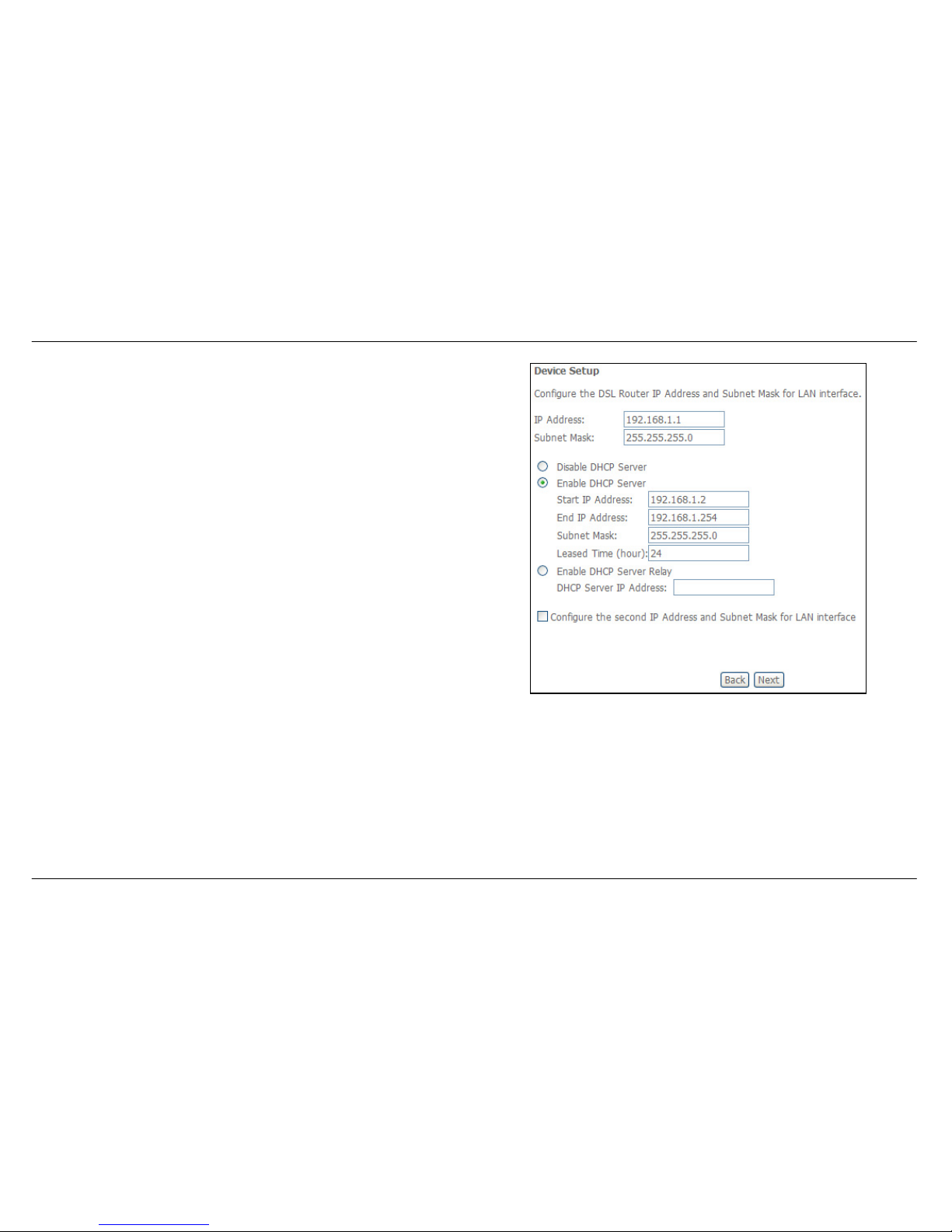
QUICK SETUP – MER
This window allows you to enter an IP address and subnet mask for the
LAN interface. In addition, you can either enable or disable the DHCP
server.
To enable the DHCP server, enter a starting IP address, an ending IP
address, and a subnet mask. You may also choose to change the default
value of the leased time. Click the Next button to continue.
Page 34
Section 3 – Configuration
D-Link DSL-2542B User Manual
34
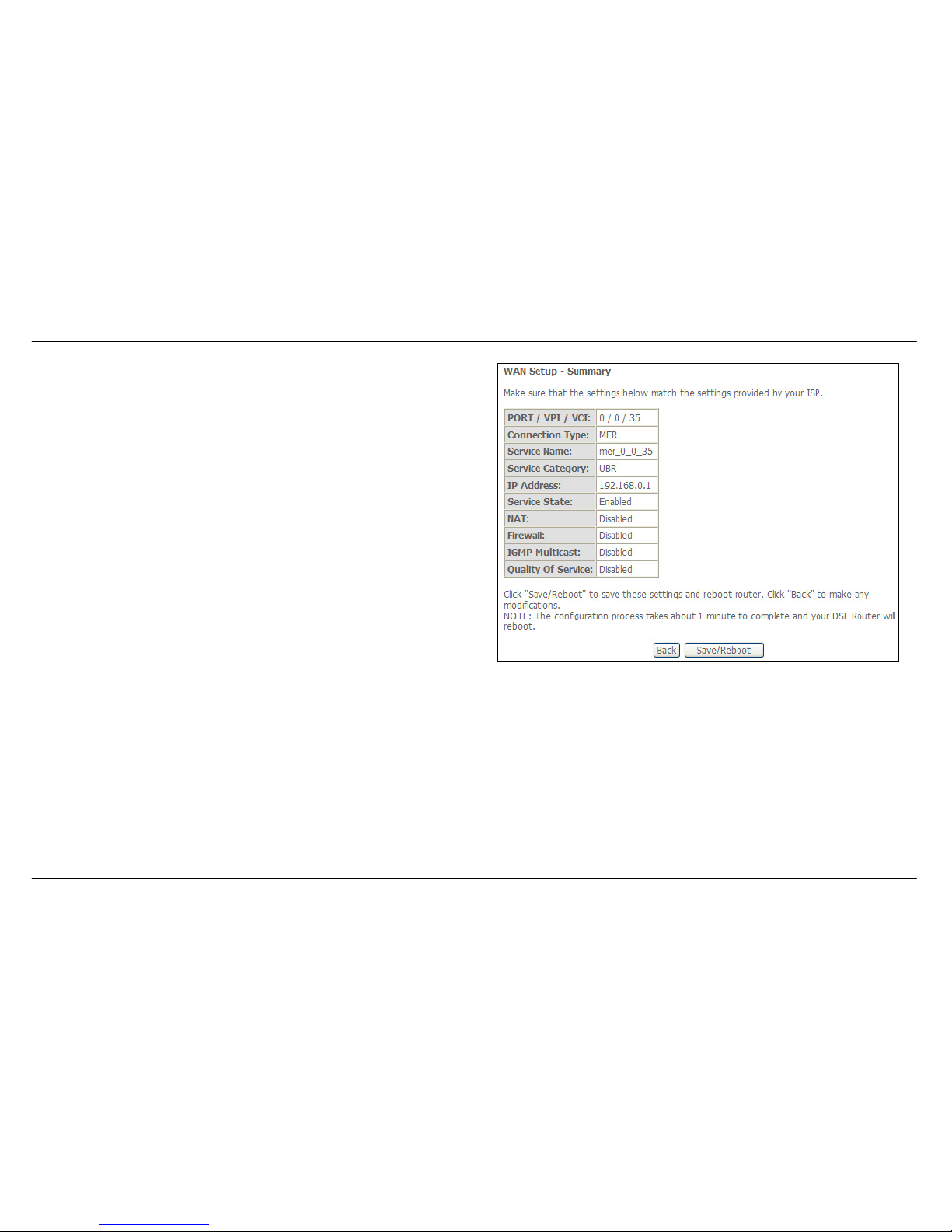
QUICK SETUP – MER
This summary window allows you to confirm the settings you have just
made. Click the Save/Reboot button to save your new MAC
Encapsulation Routing settings and restart the Router.
Page 35
Section 3 – Configuration
D-Link DSL-2542B User Manual
35
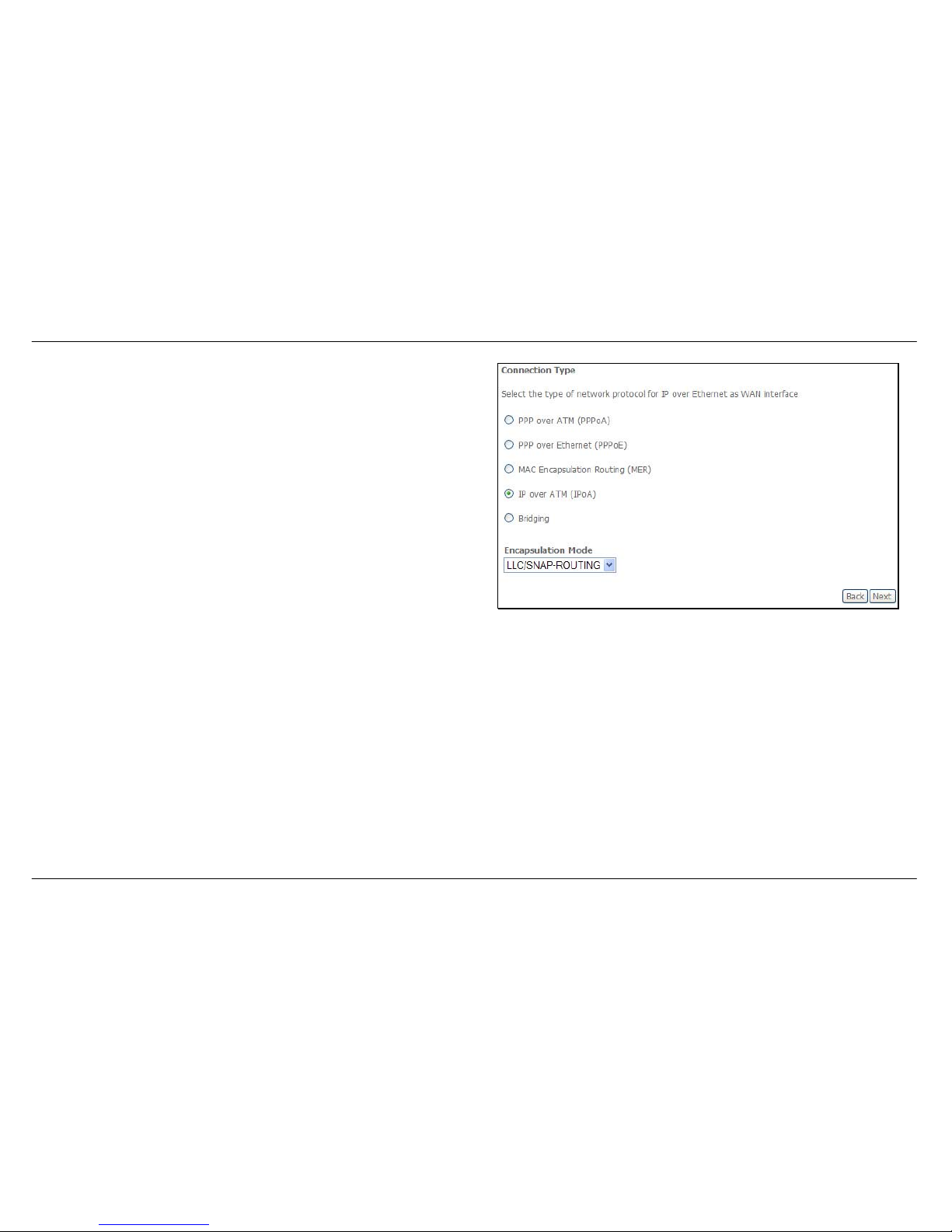
QUICK SETUP – IPoA
Click the IP over ATM (IPoA) radio button on this window. This window
also allows you to use the drop-down menu to select the desired
Encapsulation Mode. Click the Next button to continue.
Page 36
Section 3 – Configuration
D-Link DSL-2542B User Manual
36
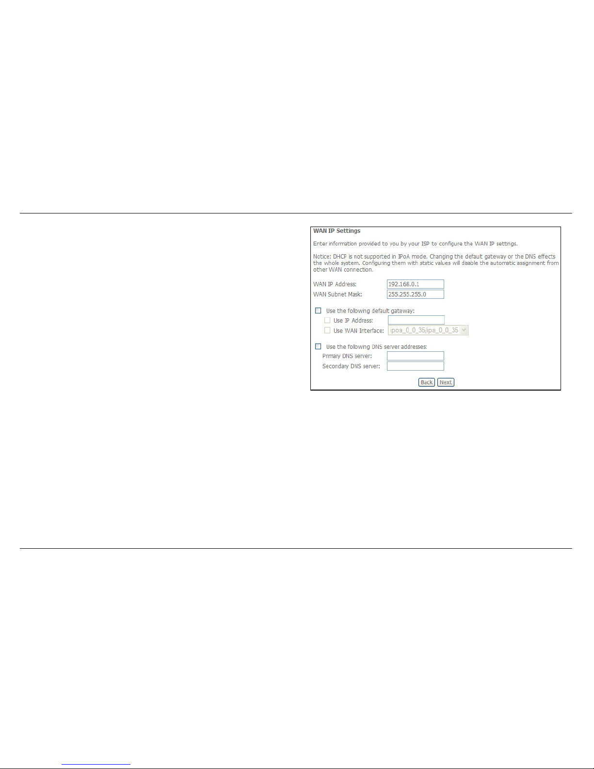
QUICK SETUP – IPoA
This window allows you to configure the WAN IP settings. This information
is obtained from your ISP. Click the Next button to continue.
Page 37
Section 3 – Configuration
D-Link DSL-2542B User Manual
37
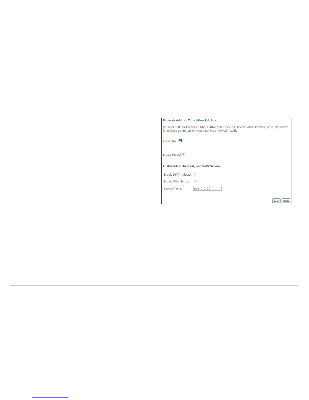
QUICK SETUP – IPoA
This window allows you to enable or disable Network Address Translation
and a firewall for your Router. In addition, you can enable or disable IGMP
multicasting and WAN service. Click the Next button to continue.
Page 38
Section 3 – Configuration
D-Link DSL-2542B User Manual
38
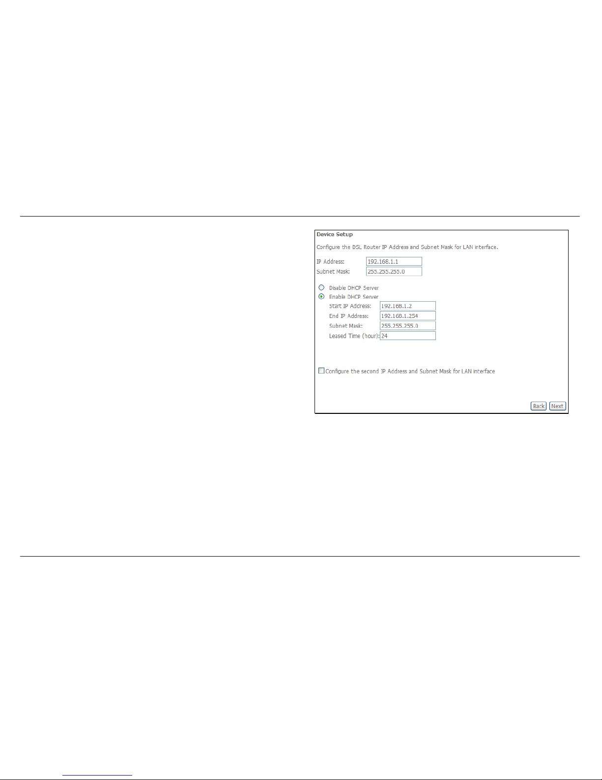
QUICK SETUP – IPoA
This window allows you to enter an IP address and subnet mask for the
LAN interface. In addition, you can either enable or disable the DHCP
server.
To enable the DHCP server, enter a starting IP address, an ending IP
address, and a subnet mask. You may also choose to change the default
value of the leased time. Click the Next button to continue.
Page 39
Section 3 – Configuration
D-Link DSL-2542B User Manual
39
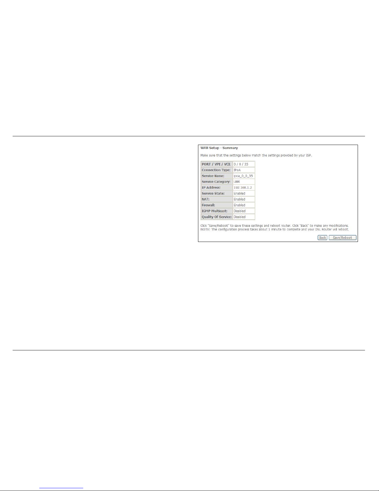
QUICK SETUP – IPoA
This summary window allows you to confirm the settings you have just
made. Click the Save/Reboot button to save your new IP over ATM
settings and restart the Router.
Page 40
Section 3 – Configuration
D-Link DSL-2542B User Manual
40
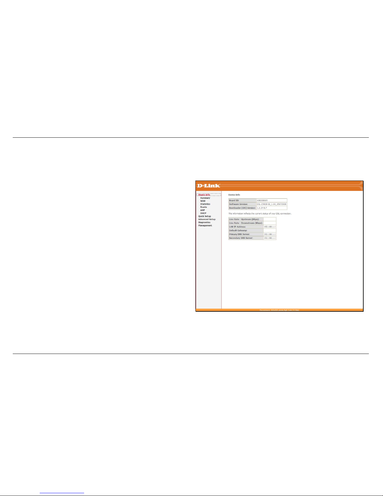
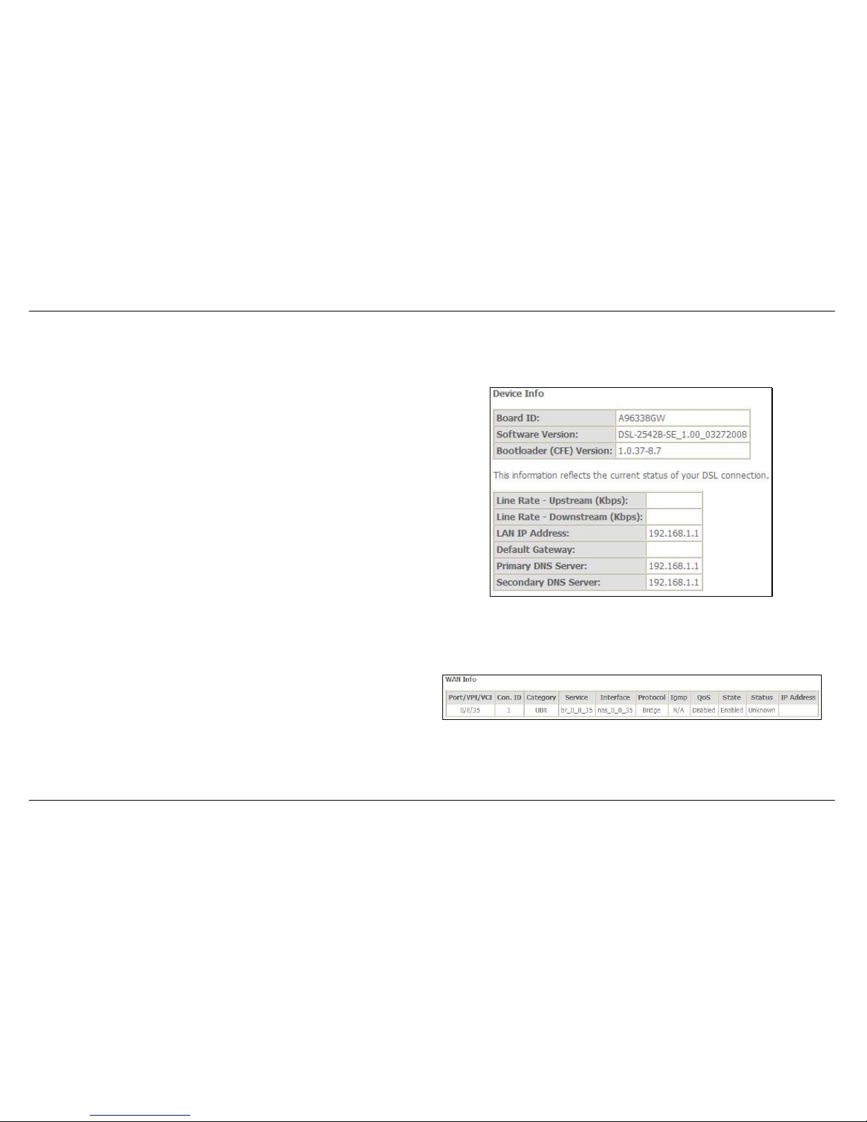
Device Info
To access the Device Info window, click either the Device Info or Summary button in the Device Info directory. The following page opens:
Page 41
Section 3 – Configuration
D-Link DSL-2542B User Manual
41
Summary
This window displays the current status of your DSL connection, including
the software version, LAN IP address, and DNS server address.
WAN
To access the WAN Info window, click the WAN button in the Device Info directory.
This window displays the current status of your WAN connection.
Page 42
Section 3 – Configuration
D-Link DSL-2542B User Manual
42
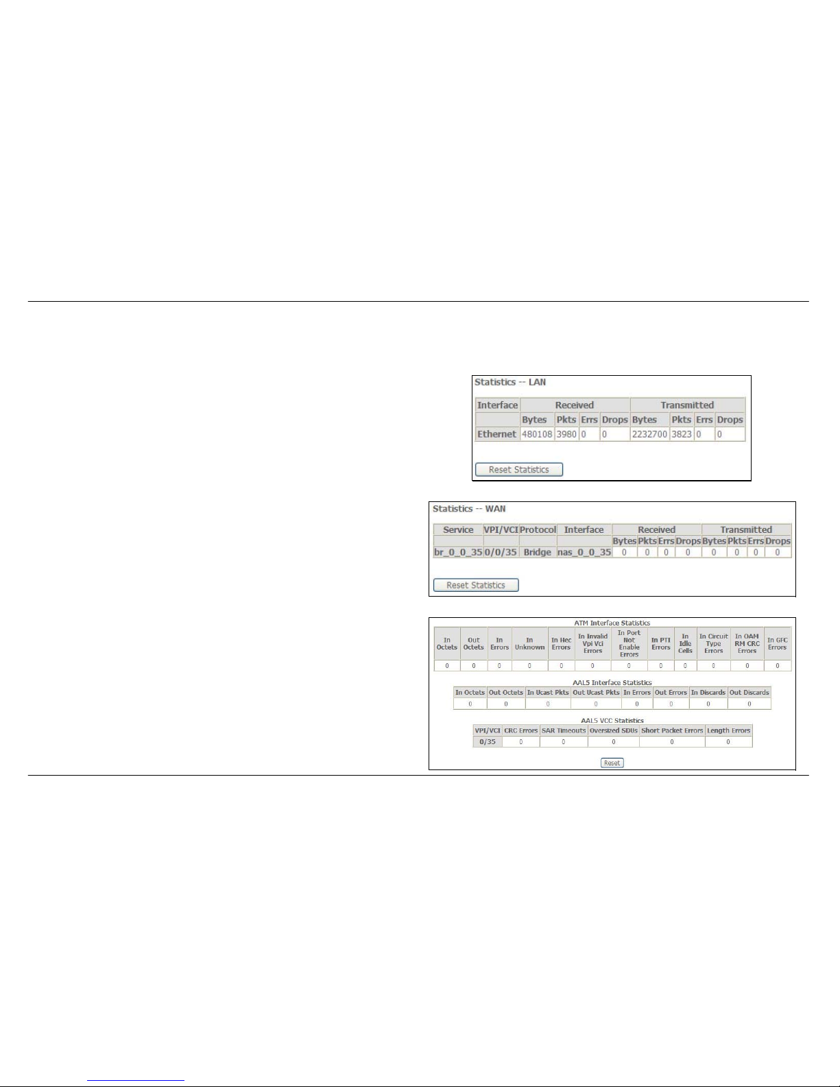
Statistics
To access the Router’s first Statistics window, click the Statistics button in the Device Info directory.
This window displays the Router’s LAN statistics. Click the Reset
Statistics button to refresh these statistics.
This window displays the Router’s WAN statistics. Click the Reset
Statistics button to refresh these statistics.
This window displays the Router’s ATM statistics. Click the Reset button
to refresh these statistics.
Page 43
Section 3 – Configuration
D-Link DSL-2542B User Manual
43
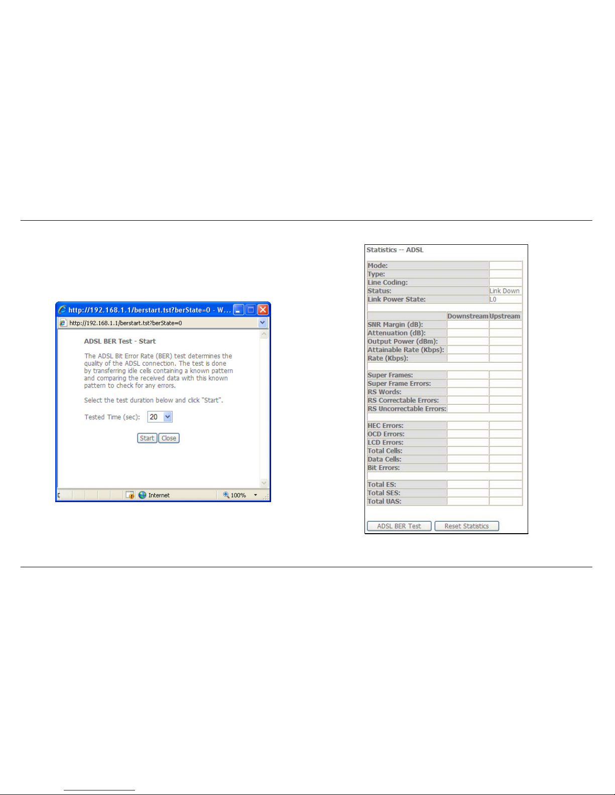
This window displays the Router’s ADSL statistics. Click the Reset
Statistics button to refresh these statistics.
Click the ADSL BER Test button to access the ADSL Bit Error Rate Test
window displayed below:
Page 44
Section 3 – Configuration
D-Link DSL-2542B User Manual
44
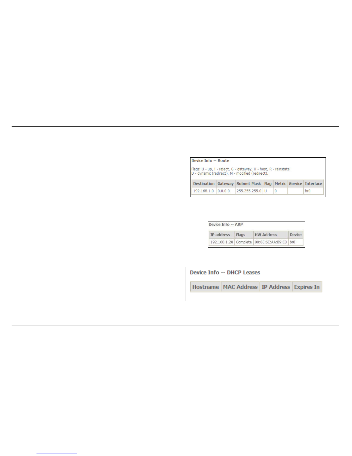
Route
To access the Device Info – Route window, click the Route button in the Device Info directory.
This read-only window displays routing info.
ARP
To access the Device Info – ARP window, click the ARP button in the Device Info directory.
This read-only window displays Address Resolution Protocol info.
DHCP
To access the Device Info – DHCP Leases window, click the DHCP button in the Device Info directory.
This read-only window displays DHCP lease info.
Page 45
Section 3 – Configuration
D-Link DSL-2542B User Manual
45
Advanced Setup
This chapter include the more advanced features used for network management and security as well as administrative tools to manage the Router,
view status and other information used to examine performance and for troubleshooting.
WAN
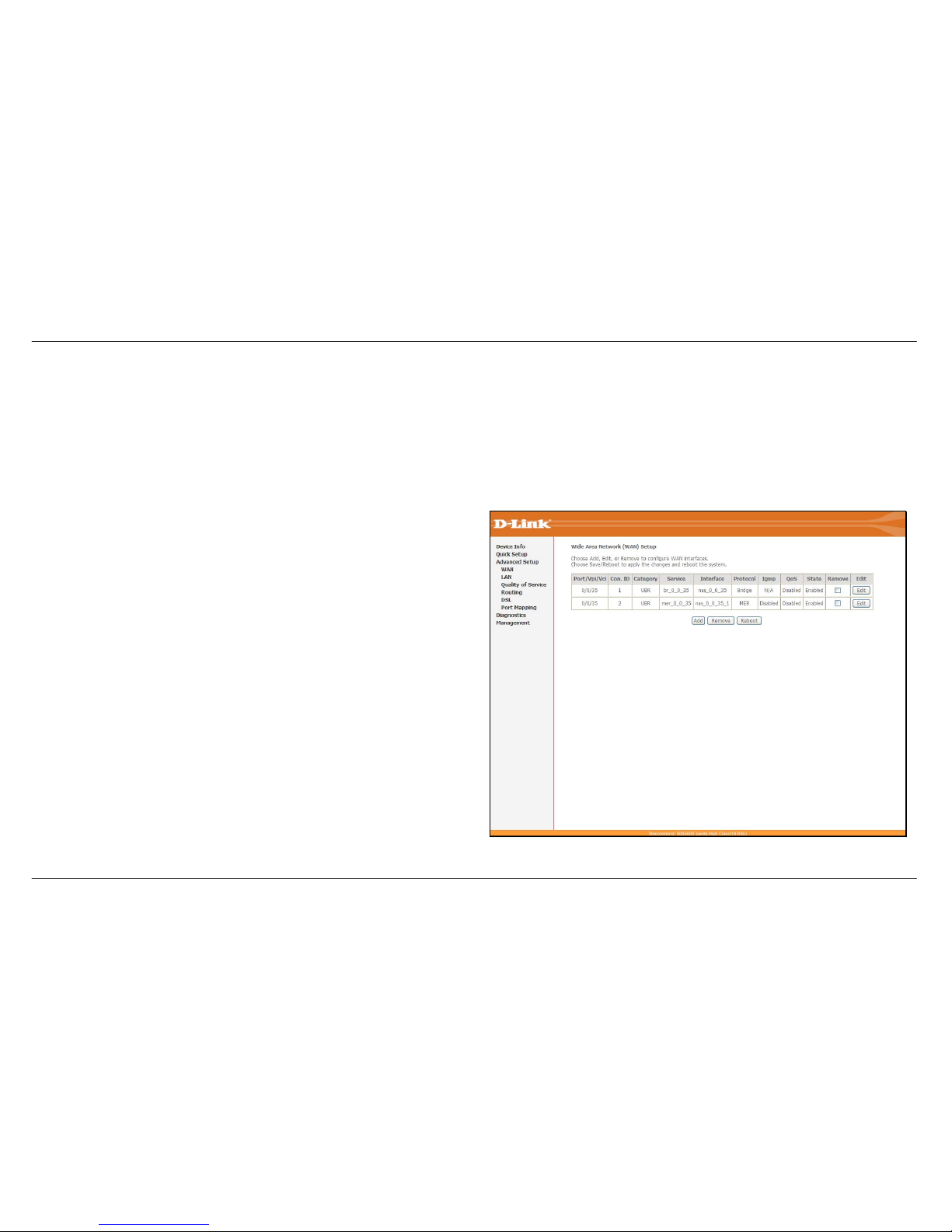
To access the Wide Area Network (WAN) Setup window, click the WAN button in the Advanced Setup directory.
This window is used to configure the WAN interface. You can add, delete,
and modify WAN interfaces on this window.
Once the desired changes to the WAN interface are complete, click the
Save/Reboot button.
If you are setting up the WAN interface for the first time, click the Add
button.
Page 46
Section 3 – Configuration
D-Link DSL-2542B User Manual
46
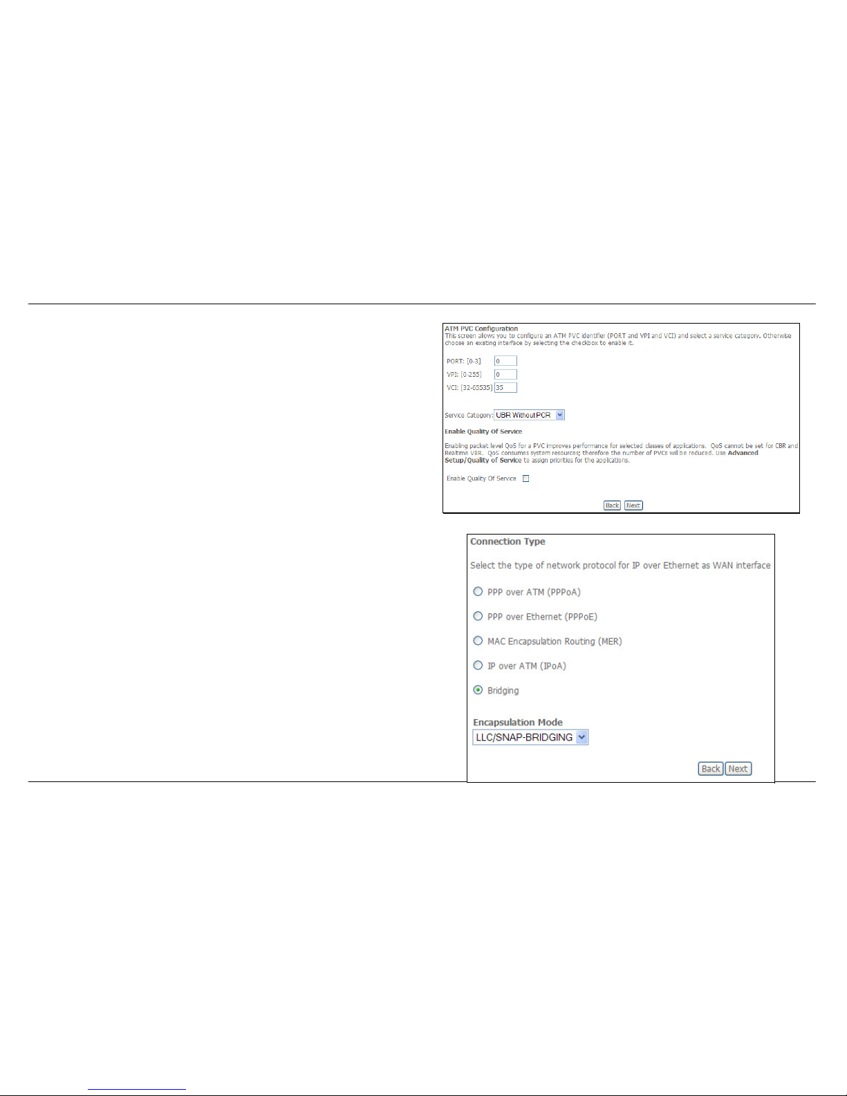
The ATM PVC Configuration window allows you to set up an ATM PVC
configuration. Enter a Port Identifier, Virtual Path Identifier, and Virtual
Channel Identifier. The VPI and VCI values should be provided by your
ISP. This window also allows you to enable QoS by ticking the Enable
Quality of Service check box. Click the Next button to continue.
This window allows you to select the appropriate connection type. The
choices include PPP over ATM (PPPoA), PPP over Ethernet (PPPoE),
MAC Encapsulation Routing (MER), IP over ATM (IPoA), and Bridging
(default).
This window also allows you to use the drop-down menu to select the
desired Encapsulation Mode. Click the Next button to continue.
For further information about each of the five connection types available
on the Router, please go to the Quick Setup section earlier in this manual
as all of the windows are identical.
Page 47
Section 3 – Configuration
D-Link DSL-2542B User Manual
47
LAN
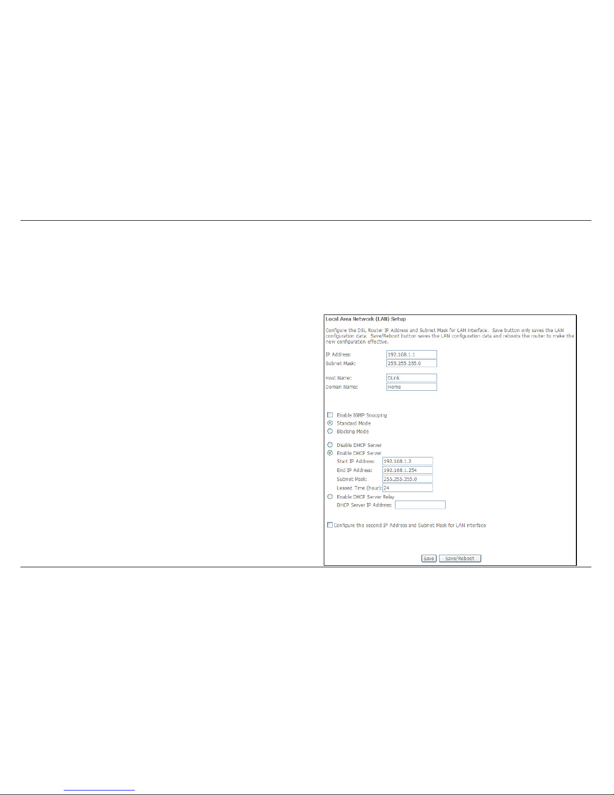
You can configure the LAN IP address to suit your preference. Many users will find it convenient to use the default settings together with the DHCP
service to manage the IP settings for their private network. The IP address of the Router is the base address used for DHCP. In order to use the
Router for DHCP on your LAN, the IP address pool used for DHCP must be compatible with the IP address of the Router. The IP addresses
available in the DHCP IP address pool will change automatically if you change the IP address of the Router.
To access the Local Area Network (LAN) Setup window, click the LAN link in the Advanced Setup directory.
This window allows you to set up a LAN interface. When you are finished,
click either the Save or Save/Reboot button.
Page 48
Section 3 – Configuration
D-Link DSL-2542B User Manual
48
NAT
To access the Network Address Translation (NAT) Setup window, click the NAT button in the Advanced Setup directory. The NAT button
appears when configuring WAN interface in PPPoA, PPPoE, MER or IPoA.
Virtual Servers
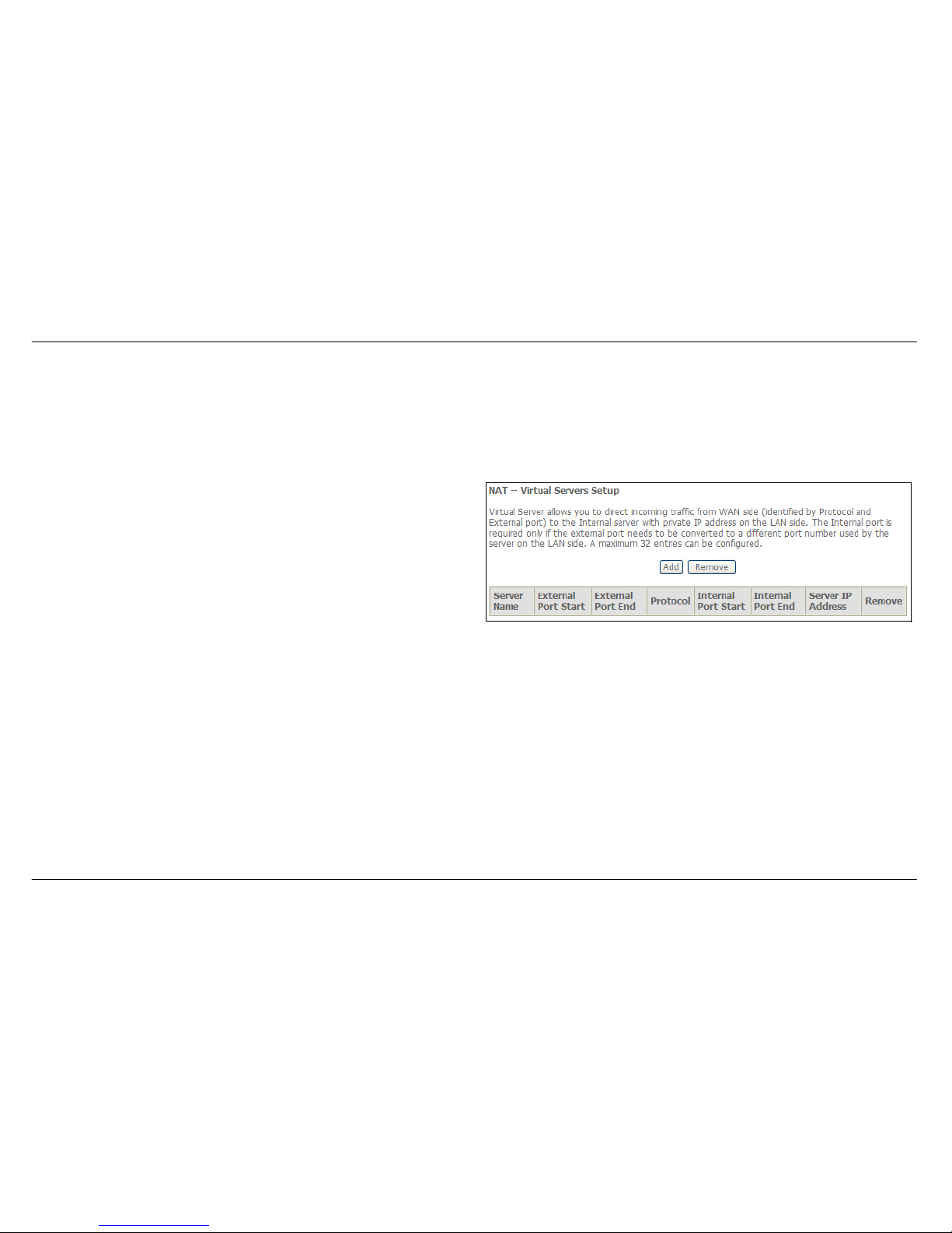
This window is used to configure virtual server. You can add, delete, and
modify virtual server on this window.
If you are setting up the virtual server, click the Add button.
Page 49
Section 3 – Configuration
D-Link DSL-2542B User Manual
49
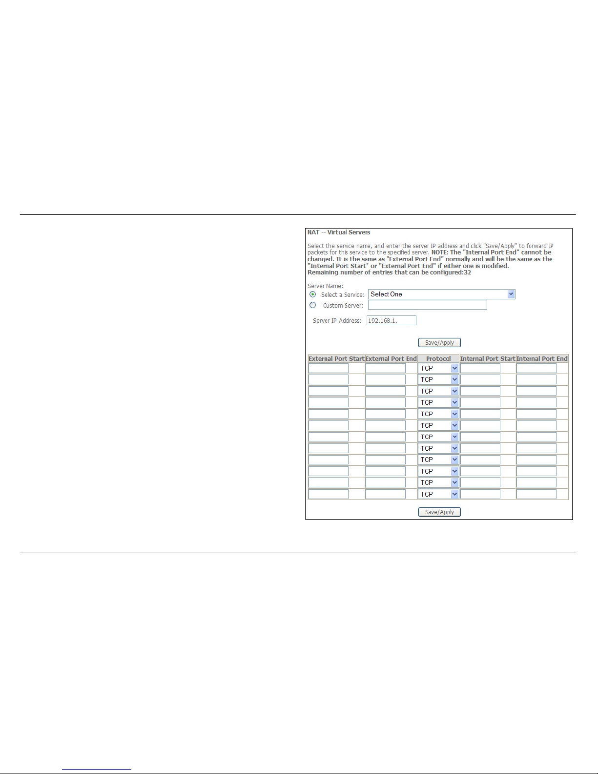
You can configure the service settings on this window by clicking the
Select a Service radio button and then using the drop-down list to choose
an existing service, or by clicking the Custom Server radio button and
entering your own Application Rule in the field provided.
Click Save/Apply when you are finished with the virtual server
configuration.
Page 50
Section 3 – Configuration
D-Link DSL-2542B User Manual
50
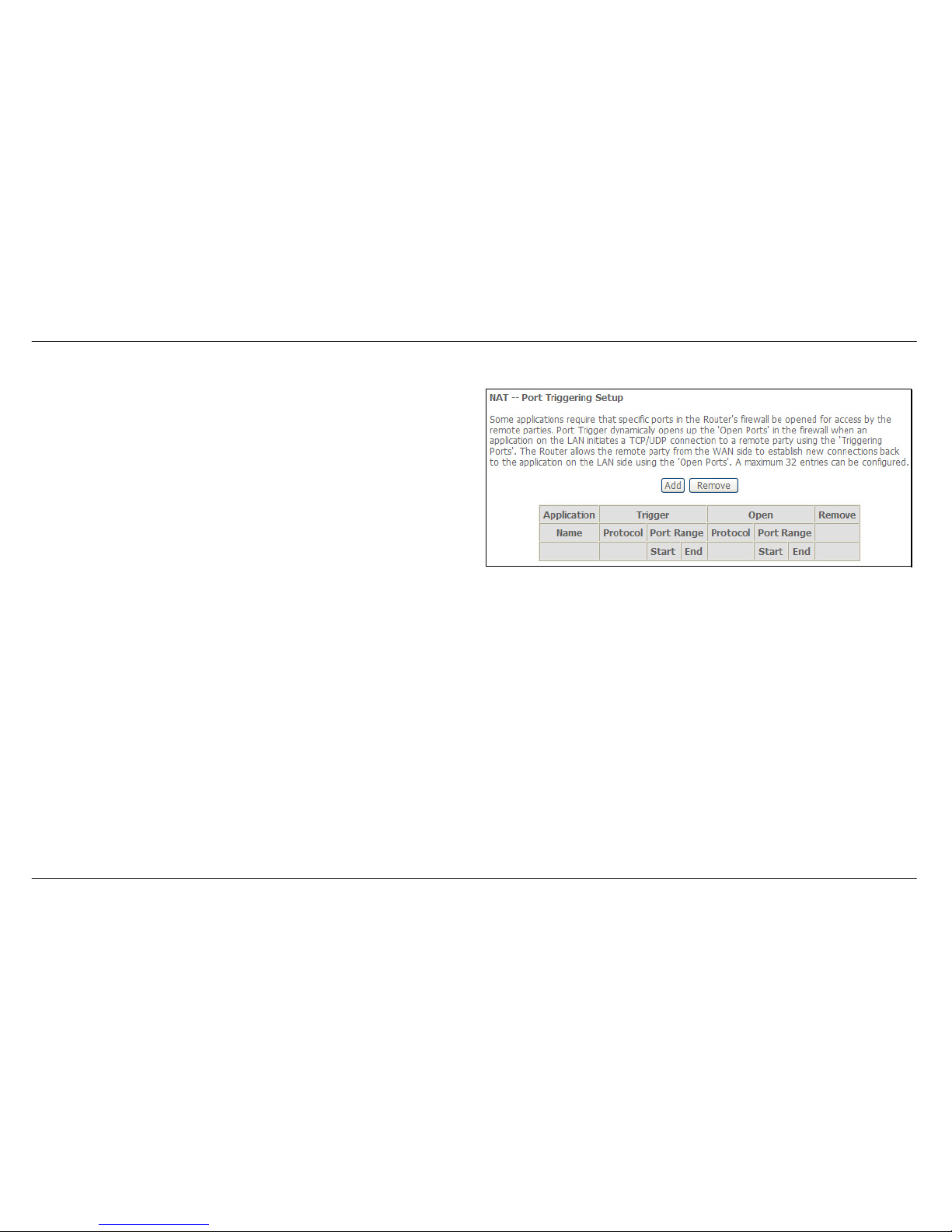
Port Triggering
Some applications require that the remote parties open specific ports in
the Router’s firewall for access. Port Trigger dynamically opens the Open
Ports in the firewall when an application on the LAN initiates a TCP/UDP
connection to a remote party using Trigger Ports. The Router allows the
remote party form the WAN side to establish new connections back to the
application on the LAN side using the Open Ports.
Applications such as games, video conferencing, and other remote
access applications require that specific ports in the Router’s firewall be
opened for access by applications.
Click the Add button to configure port triggering.
Page 51
Section 3 – Configuration
D-Link DSL-2542B User Manual
51
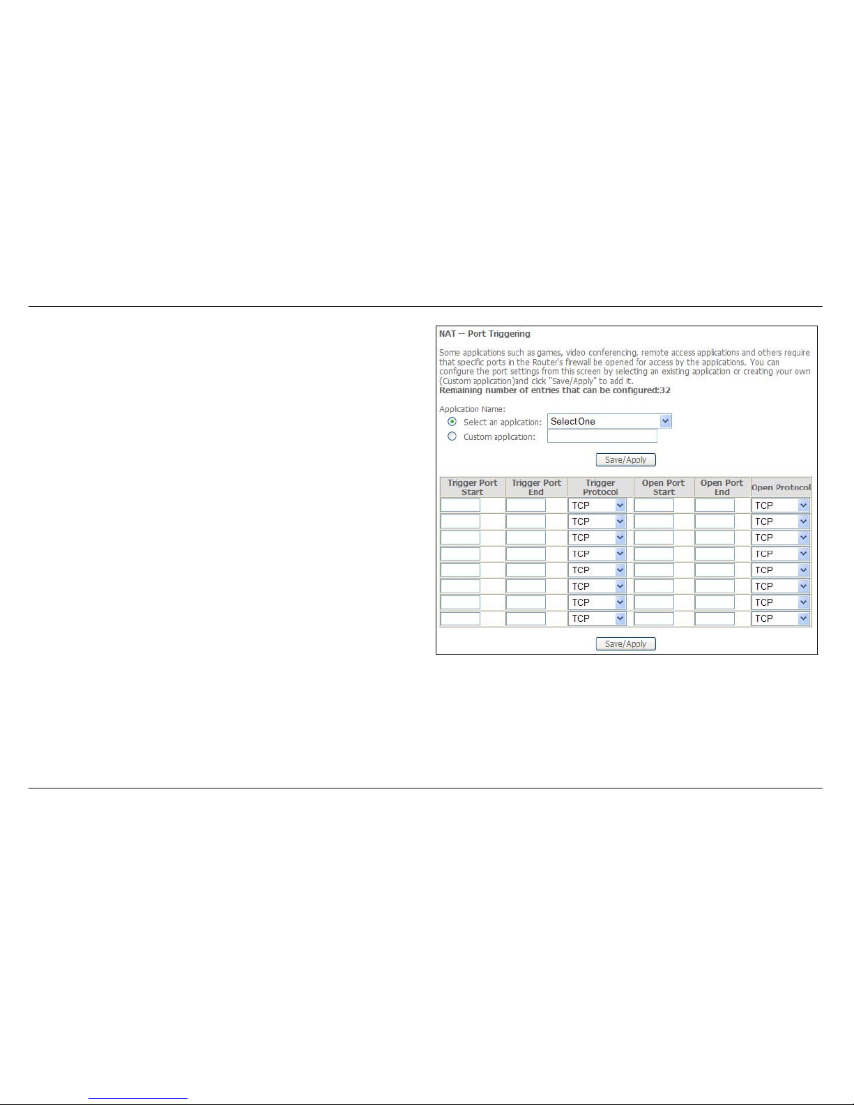
You can configure the port settings on this window by clicking the Select
an application radio button and then using the drop-down list to choose
an existing application, or by clicking the Custom application radio
button and entering your own Application Rule in the field provided.
Click Save/Apply when you are finished with the port setting
configuration. The new Application Rule will appear in the Port Triggering
table.
Page 52
Section 3 – Configuration
D-Link DSL-2542B User Manual
52
DMZ Host
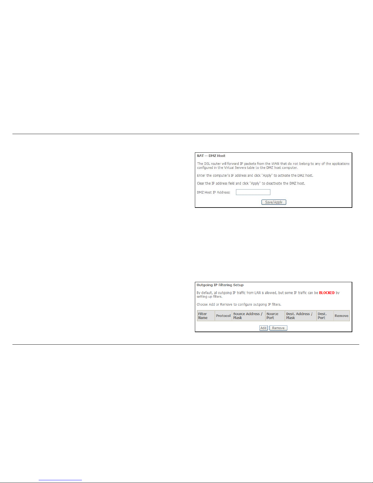
Since some applications are not compatible with NAT, the Router supports
use of a DMZ IP address for a single host on the LAN. This IP address is
not protected by NAT and will therefore be visible to agents on the Internet
with the right type of software. Keep in mind that any client PC in the DMZ
will be exposed to various types of security risks. If you use the DMZ, take
measures (such as client-based virus protection) to protect the remaining
client PCs on your LAN from possible contamination through the DMZ.
To designate a DMZ IP address, type in the IP Address of the server or
device on your LAN, and click the Save/Apply button.
Security
To access the Security window, click the Security button in the Advanced Setup directory. The Security button appears after configuring WAN
interface.
IP Filtering
The IP Filtering button appears when configuring WAN interface in PPPoA, PPPoE, MER or IPoA.
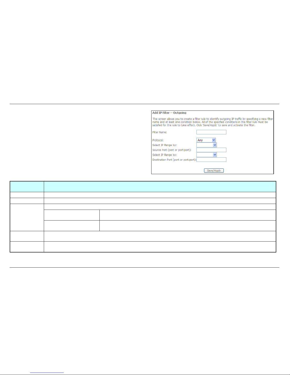
IP Filtering - Outgoing
This window allows you to create a filter rule to block outgoing IP traffic by
specifying a filter name and at least one condition on this window. All of
the specified conditions in this filter rule must be satisfied for the rule to
take effect. Filters are used to allow or deny LAN or WAN users from
accessing the Internet or your internal network.
If you are setting up the outgoing IP filtering, click the Add button.
Page 53
Section 3 – Configuration
D-Link DSL-2542B User Manual
53
Enter the information in the section. Explanations of parameters are
described below. Click the Save/Apply button to add the entry in the
Active Outbound IP Filtering table.
Filters
Parameter
Description
Filter Name Enter a name for the new filter.
Protocol Select the transport protocol (Any, TCP/UDP, TCP, UDP or ICMP) that will be used for the filter rule.
Select either IP address or Netmask to show different items.
Source IP Address Enter the start and end IP address for the range of IP addresses which you are creating the
filter rule.
Select IP Range
by
Source IP Address & Source
Subnet Mask
This is the IP address and their associated subnets for which you are creating the filter rule.
Source Port The Source Port is the TCP/UDP port on either the LAN or WAN depending on if you are configuring an Outbound or Inbound
Filter rule.
Destination Port The Destination Port is the TCP/UDP port on either the LAN or WAN depending on if you are configuring an Outbound or
Inbound Filter rule.
Page 54
Section 3 – Configuration
D-Link DSL-2542B User Manual
54
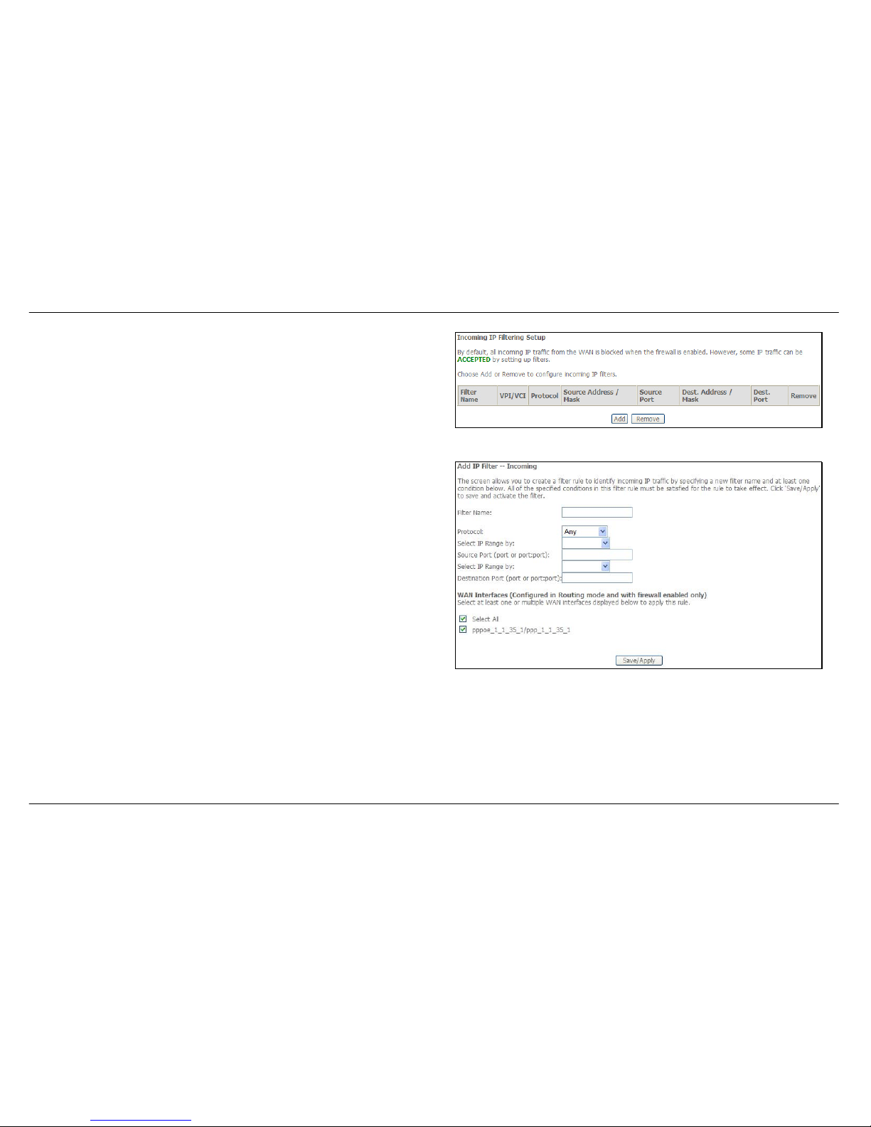
IP Filtering – Incoming
The Inbound Filter allows you to create a filter rule to allow incoming IP
traffic by specifying a filter name and at least one condition on this
window. All of the specified conditions in this filter rule must be satisfied
for the rule to take effect. By default, all incoming IP traffic from the
Internet is blocked when the firewall is enabled.
If you are setting up the incoming IP filtering, click the Add button.
Enter the information in the section. Explanations of parameters are
described below. Click the Save/Apply button to add the entry in the
Active Inbound IP Filtering table.
Page 55
Section 3 – Configuration
D-Link DSL-2542B User Manual
55
Filters Parameter Description
Filter Name Enter a name for the new filter.
Protocol Select the transport protocol (Any, TCP/UDP, TCP, UDP or ICMP) that will be used for the filter rule.
Select either IP address or Netmask to show different items.
Source IP Address Enter the start and end IP address for the range of IP addresses which you are creating the filter
rule.
Select IP Range by
Source IP Address &
Source Subnet Mask
This is the IP address and their associated subnets for which you are creating the filter rule.
Source Port The Source Port is the TCP/UDP port on either the LAN or WAN depending on if you are configuring an Outbound or
Inbound Filter rule.
Destination Port The Destination Port is the TCP/UDP port on either the LAN or WAN depending on if you are configuring an Outbound or
Inbound Filter rule.
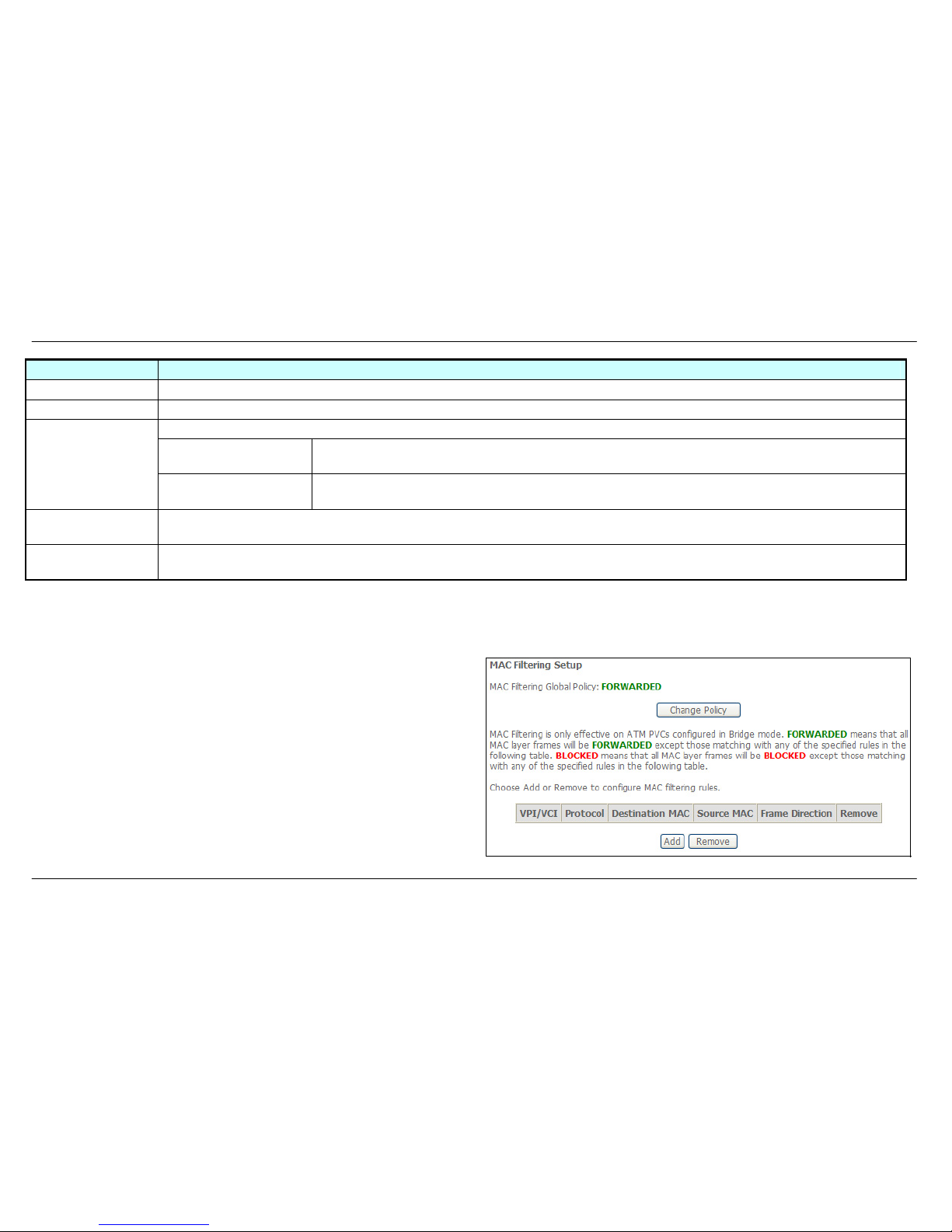
MAC Filtering
The MAC Filtering button appears when configuring WAN interface in Bridging.
MAC filtering are used to block or allow various types of packets through
the WAN/LAN interface. This may be done for security or to improve
network efficiency. The rules are configured for individual devices based
on MAC address. Filter rules can be set up for source, destination or both.
You can set up filter rules and disable the entire set of rules without
loosing the rules that have been configured.
Click Change Policy to configure the global policy as Forwarded or
Blocked.
If you are setting up the MAC filtering, click the Add button.
Page 56
Section 3 – Configuration
D-Link DSL-2542B User Manual
56
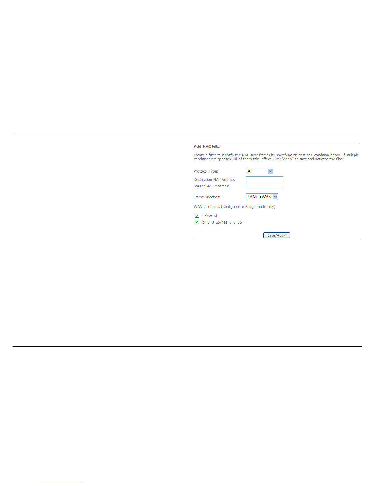
Select a protocol (All, PPPoE, IPv4, IPv6, Apple Talk, IPX, NetBEUI or
IGMP) in the Protocol Type list, type in a Destination MAC, a Source
MAC or both in the entry fields. Select a direction (LAN=>WAN,
WAN=>LAN, or LAN<=>WAN) in the Frame Direction list. Click the
Save/Apply button to add the entry in the Active Bridge Filters table.
Page 57
Section 3 – Configuration
D-Link DSL-2542B User Manual
57
Quality of Service
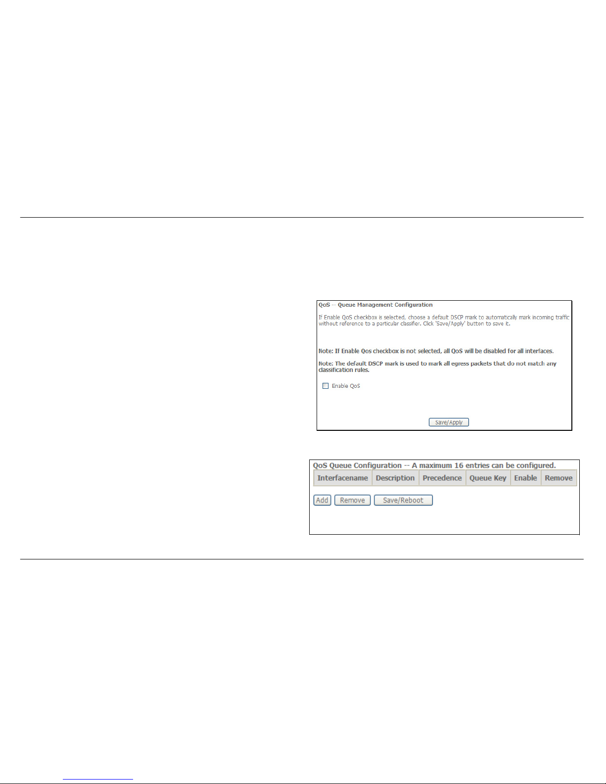
QoS or Quality of Service allows your Router to help prioritize the data packet flow in your Router and network. This is very important for time
sensitive applications such as VoIP where it may help prevent dropped calls. Large amounts of non-critical data can be scaled so as not to affect
these prioritized sensitive real-time programs.
To access the QoS – Queue Management Configuration window, click the Quality of Service link in the Advanced Setup directory.
This window allows you to set up QoS on the Router. When you are
finished, click on the Save/Apply button.
Queue Config
To add a new QoS Queue configuration, click the Queue Config link.
Click the Add button to add a new QoS Queue Configuration table entry.
Page 58
Section 3 – Configuration
D-Link DSL-2542B User Manual
58
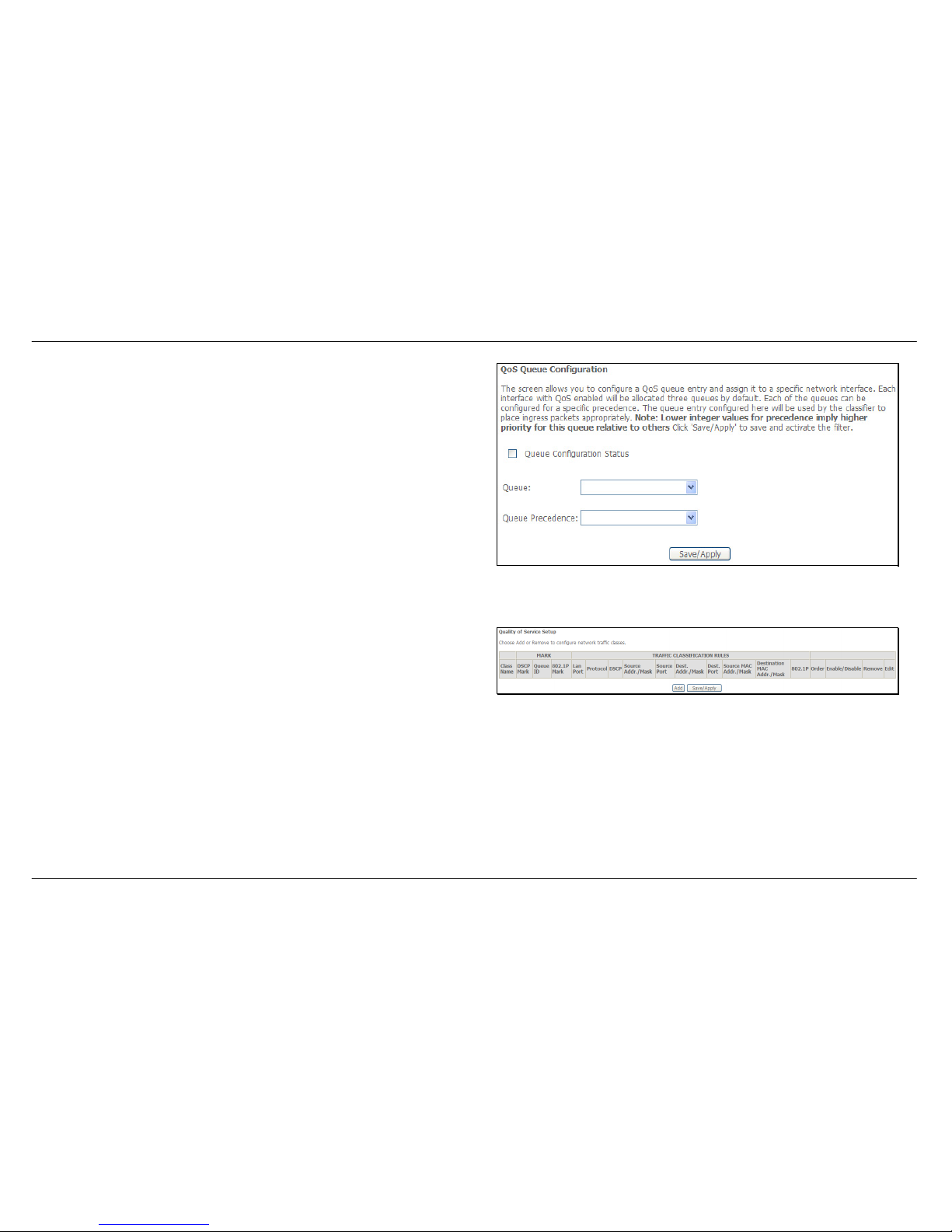
This window allows you to configure a QoS queue entry and assign it a
specific network interface.
Click the Save/Apply button to save and activate the filter.
QoS Classification
To configure QoS Classification, click the QOS Classification link.
Choose Add or Remove to configure network traffic classes.
Page 59
Section 3 – Configuration
D-Link DSL-2542B User Manual
59
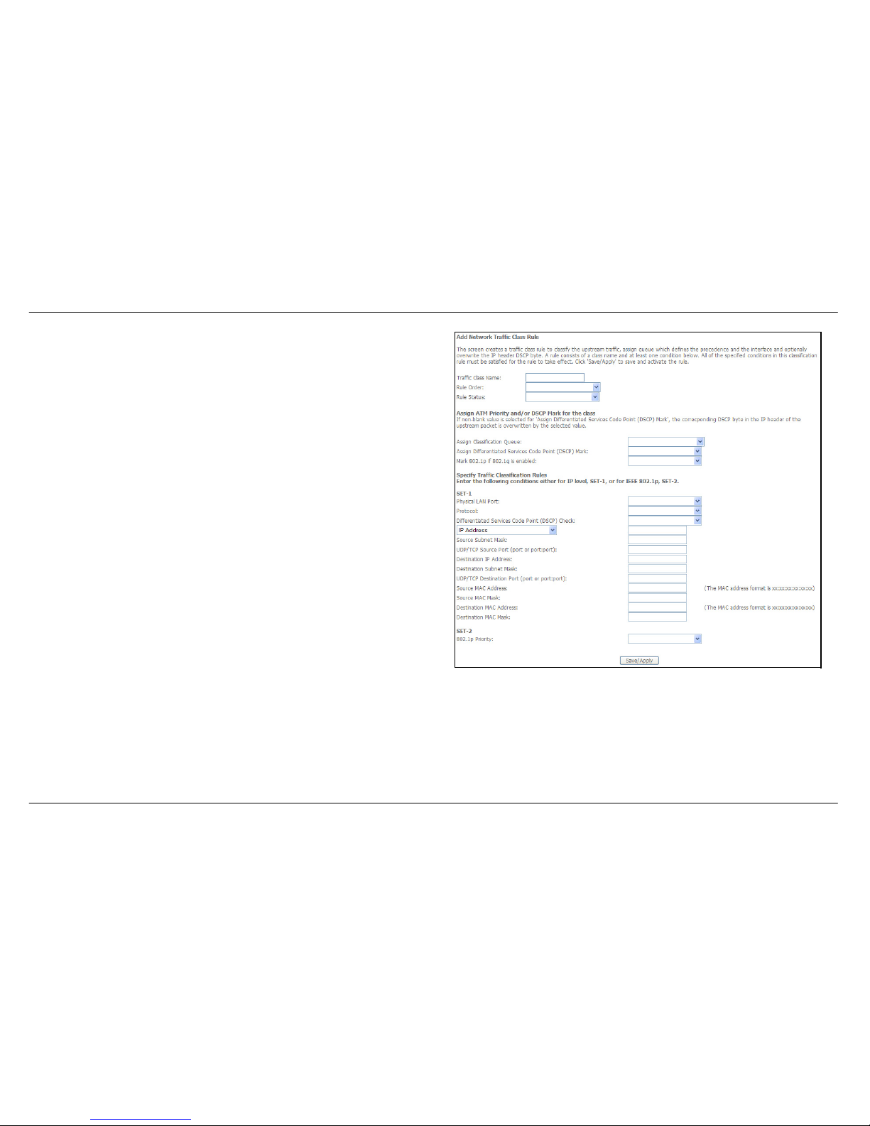
Click Add to add a new traffic class rule.
Use this window to create a traffic class rule to classify the upstream
traffic, assign a queue that defines the precedence and the interface, and
optionally overwrite the IP header DSCP byte. A rule consists of a class
name and at least one condition. Please remember that all of the specified
conditions on this window must be met for the rule to take effect.
Click the Save/Apply button to save and activate this rule.
Page 60
Section 3 – Configuration
D-Link DSL-2542B User Manual
60
Routing
To access the Routing windows, click the Routing button in the Advanced Setup directory.
Default Gateway
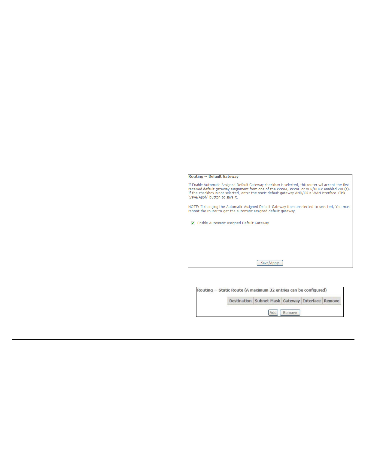
If the Enable Automatic Assigned Default Gateway checkbox is ticked,
the Router will accept the first default gateway assignment received from
one of the enabled PPPoA, PPPoE, or MER/DHCP enabled PVC(s).
If this checkbox is not ticked, enter the static default gateway and/or a
WAN interface. Click the Save/Apply button when you are finished.
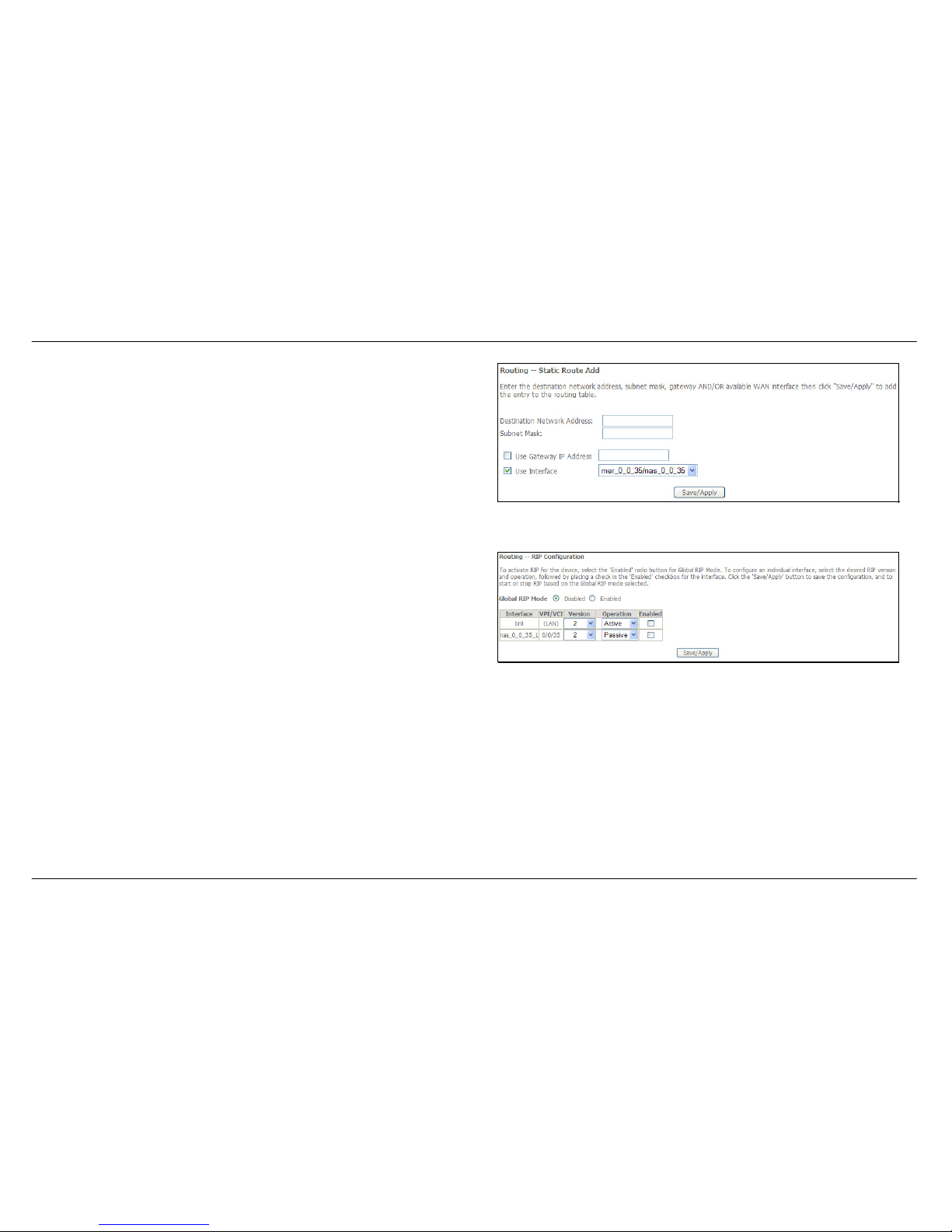
Static Route
Click the Add button on the Routing – Static Route window to access the
following window displayed on the next page.
Page 61
Section 3 – Configuration
D-Link DSL-2542B User Manual
61
Enter the static routing information for an entry to the routing table.
Click the Save/Apply button when you are finished.
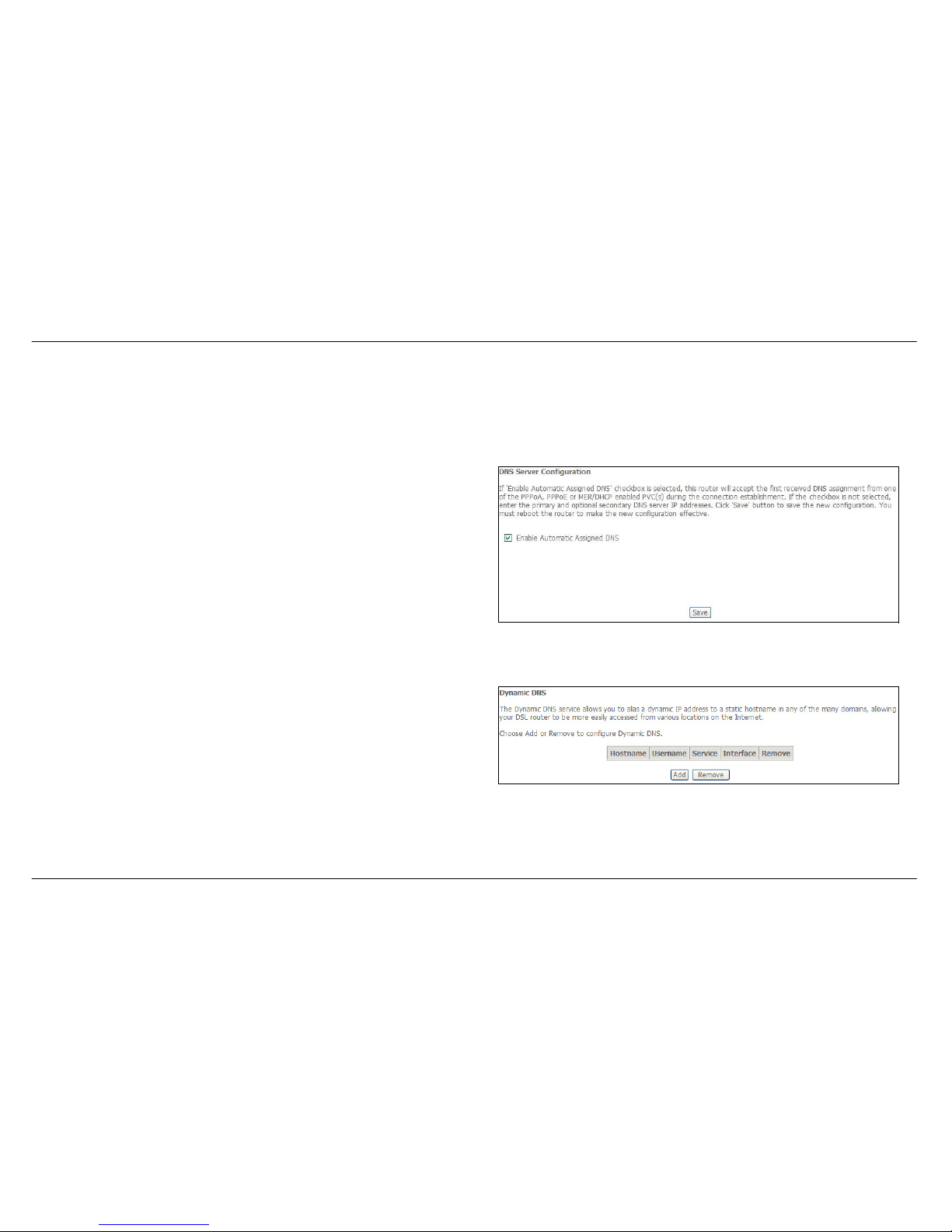
RIP
Click Enabled in Global RIP Mode, select Versio n and Operation, and
tick Enabled of the Interface.
Click the Save/Apply button to activate RIP.
Page 62
Section 3 – Configuration
D-Link DSL-2542B User Manual
62
DNS
To access the DNS windows, click the DNS button in the Advanced Setup directory. The DNS button appears when configuring WAN interface in
PPPoA, PPPoE, MER or IPoA.
DNS Server
If you have not been given specific DNS server IP addresses or if the
Router is not pre-configured with DNS server information, tick the Enable
Automatic Assigned DNS checkbox. Auto discovery DNS instructs the
Router to automatically obtain the DNS IP address from the ISP through
DHCP. If your WAN connection uses a Static IP address, auto discovery
for DNS cannot be used.
If you have DNS IP addresses provided by your ISP, deselect the Enable
Automatic Assigned DNS checkbox and enter these IP addresses in the
available entry fields for the Primary DNS Server and the Secondary DNS
Server. Click the Save button when you are finished.
Dynamic DNS
The Router supports Dynamic DNS (Dynamic Domain Name Service).
The Dynamic DNS service allows a dynamic public IP address to be
associated with a static host name in any of the many domains, allowing
access to a specified host from various locations on the Internet. This is
enabled to allow remote access to a host by clicking a hyperlinked URL in
the form hostname.dyndns.org, Many ISPs assign public IP addresses
using DHCP, this can make it difficult to locate a specific host on the LAN
using standard DNS. If for example you are running a public web server or
VPN server on your LAN, this ensures that the host can be located from
the Internet if the public IP address changes. DDNS requires that an
account be setup with one of the supported DDNS providers.
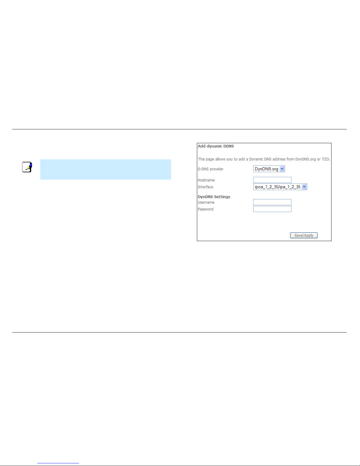
Click Add to see the Add DDNS Settings section.
Page 63
Section 3 – Configuration
D-Link DSL-2542B User Manual
63
Enter the required DDNS information, click the Save/Apply button to save
the information.
Note
DDNS requires that an account be setup with one of the supported
DDNS servers prior to engaging it on the Router. This function will not
work without an accepted account with a DDNS server.
Page 64
Section 3 – Configuration
D-Link DSL-2542B User Manual
64
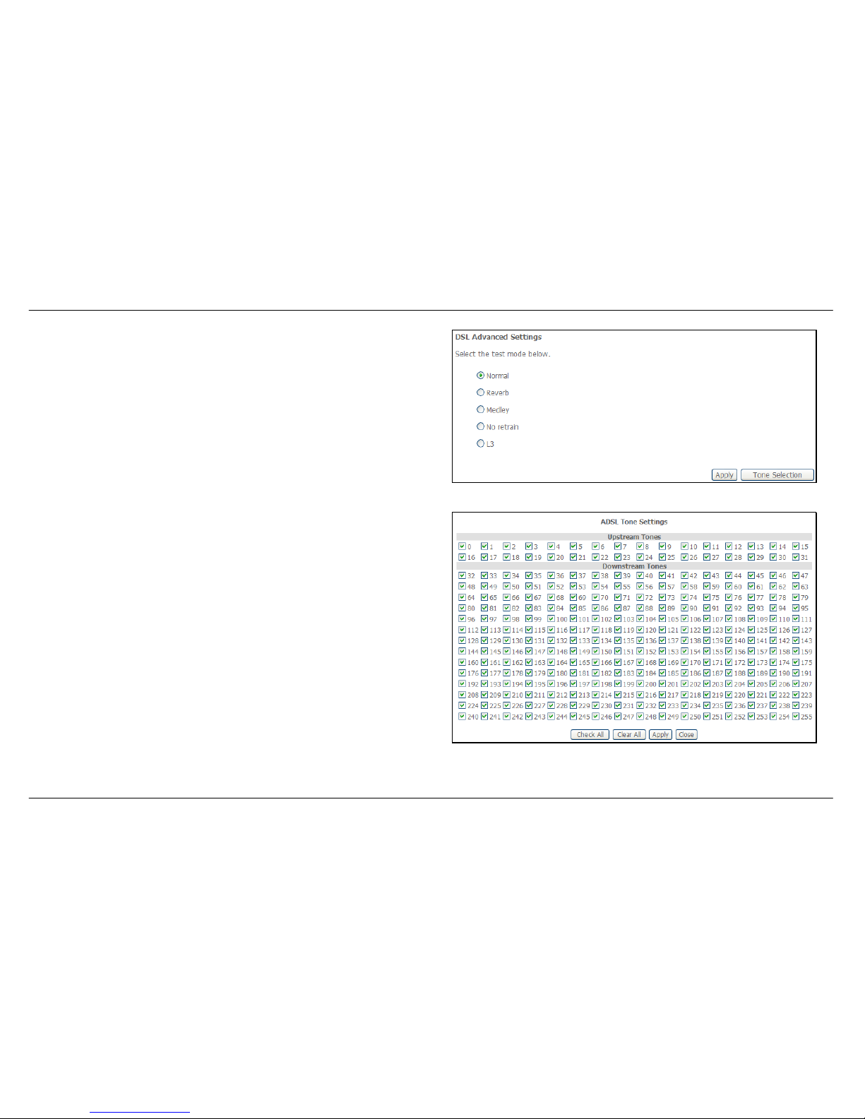
DSL
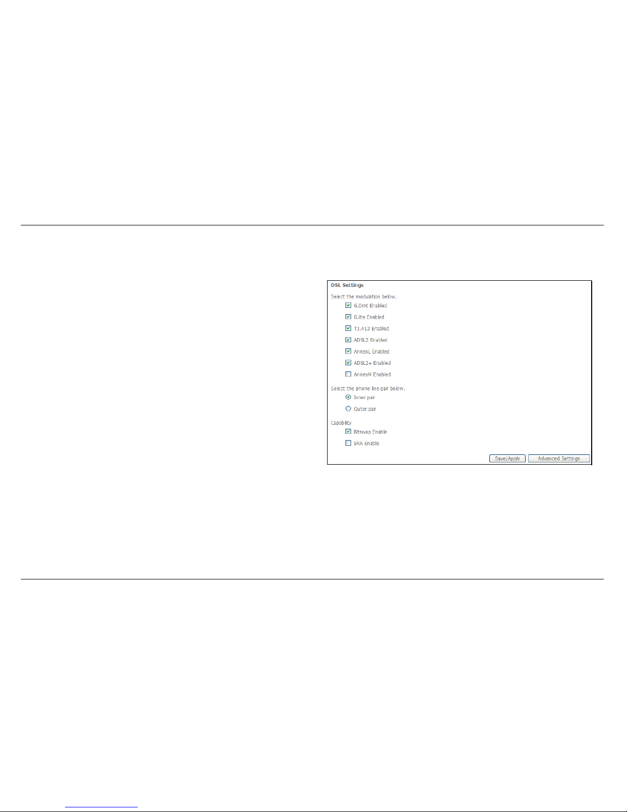
To access the DSL Settings window, click the DSL option in the Advanced Setup directory.
This window allows you to select the desired modulation, phone line pair,
and capability. Click the Save/Apply button when you are finished.
Click the Advanced Settings button to select a DSL test mode.
Page 65
Section 3 – Configuration
D-Link DSL-2542B User Manual
65
Select the desired DSL test mode and then click the Apply button.
Click the Tone Selection button to modify the upstream and downstream
tones.
Select the appropriate upstream and downstream tones for your ADSL
connection. Click the Apply button to let your settings take effect.
Page 66
Section 3 – Configuration
D-Link DSL-2542B User Manual
66
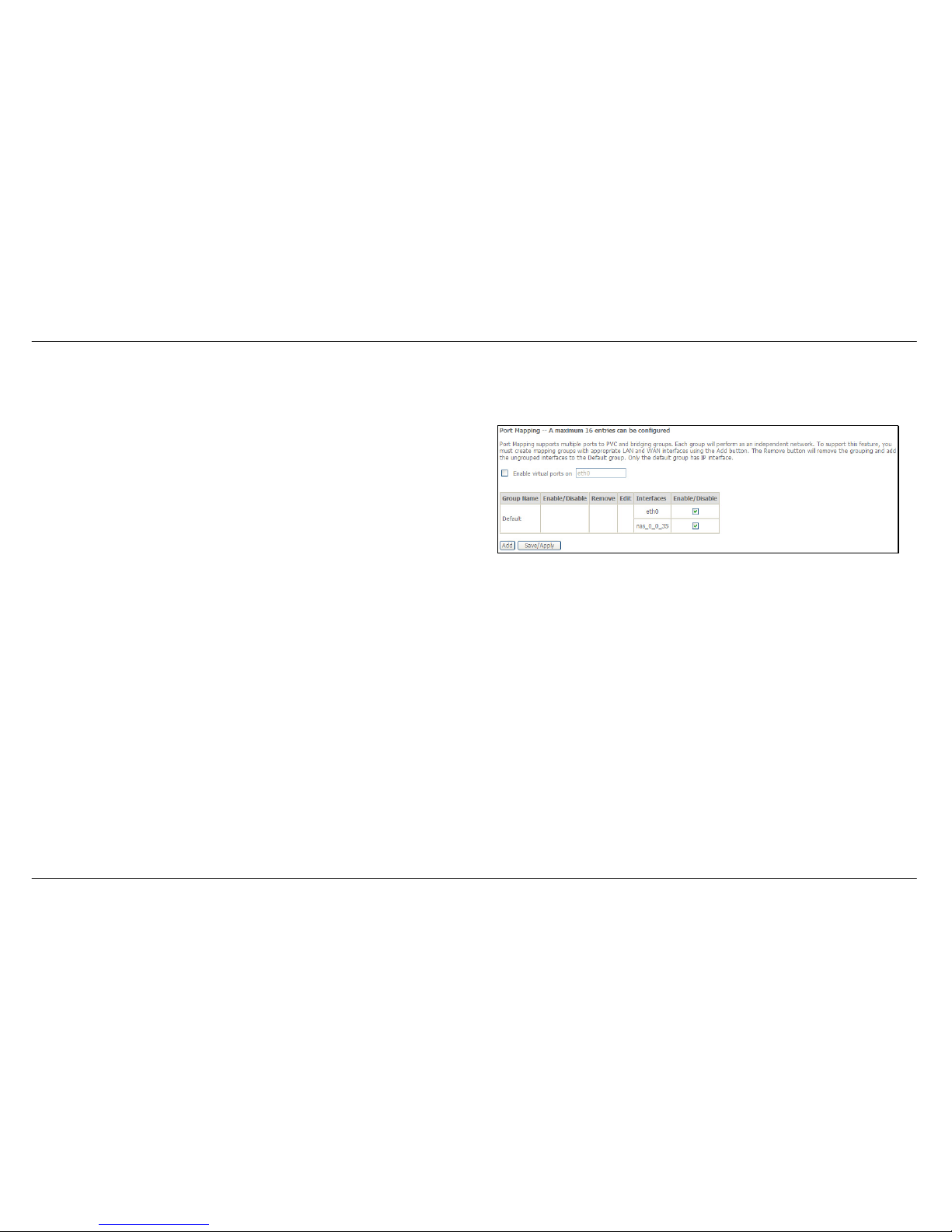
Port Mapping
To access the Port Mapping window, click the Port Mapping button in the Advanced Setup directory.
Use this window to enable port mapping. Tick Enable virtual ports on
and enter
If you are setting up the mapping groups, click the Add button.
Page 67
Section 3 – Configuration
D-Link DSL-2542B User Manual
67
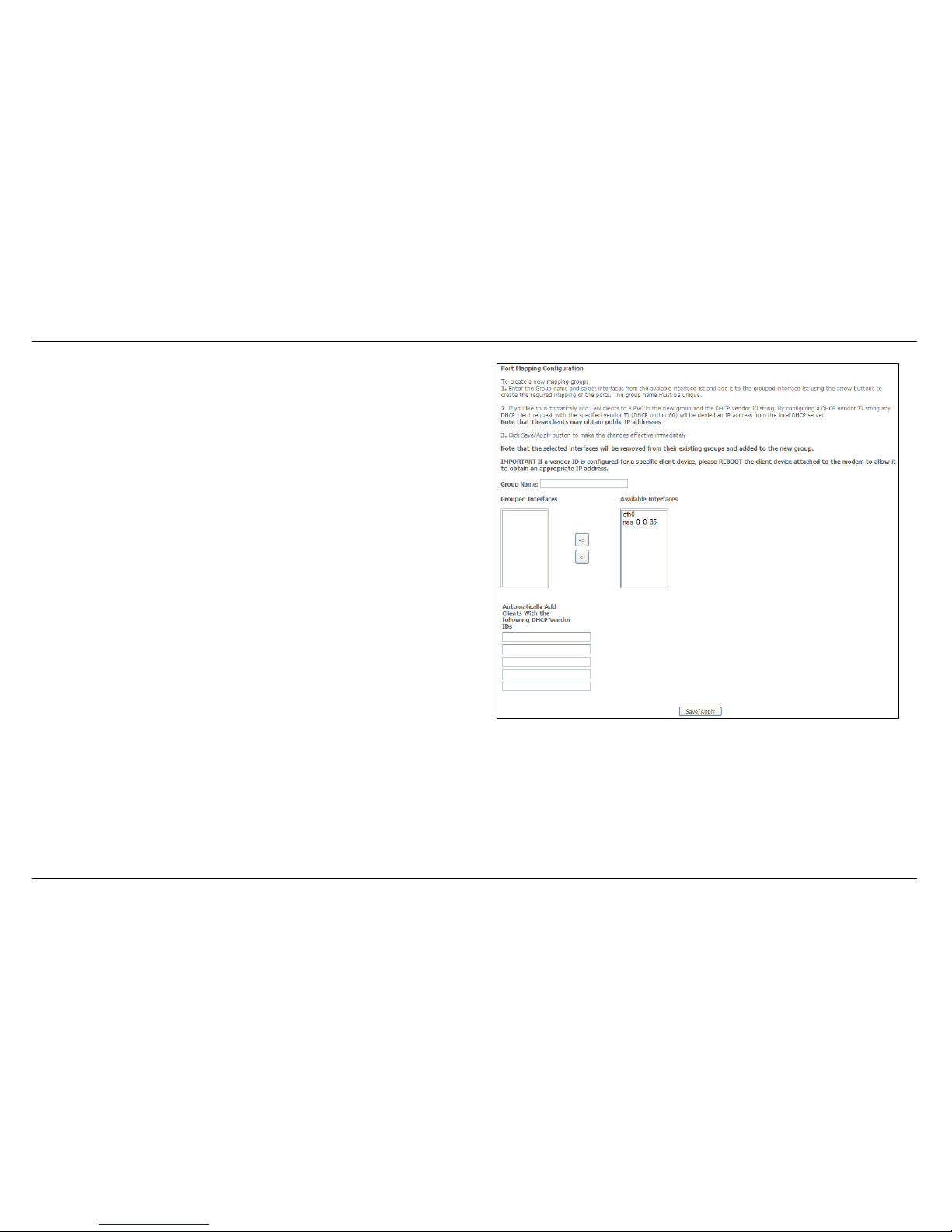
To create a new mapping group, enter Group Name, add interfaces to
Grouped Interfaces.
Click Save/Apply to save the changes.
Page 68
Section 3 – Configuration
D-Link DSL-2542B User Manual
68
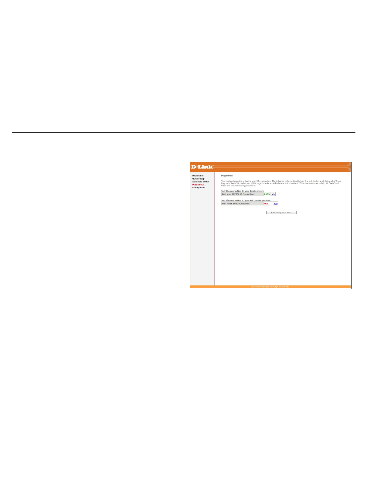
Diagnostics
To access the Diagnostics window, click the Diagnostics link.
This window is used to test connectivity of the Router.
Click the Test button to test the network connection to your local network
and your DSL service provider.
The Diagnostics window also allows you to test the network connection
with OAM F4. Click the Test with OAM F4 button to carry out this type of
test.
To test another connection on the Router click the Next/Previous
Connection button.
Page 69
Section 3 – Configuration
D-Link DSL-2542B User Manual
69
Management
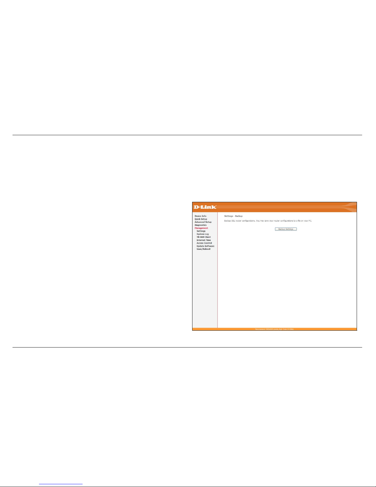
The Management directory features an array of options designed to help you get the most out of your Router.
Settings
The Settings window allows you to backup the Router configuration, update the router configuration and restore the router to default settings.
The SettingsÆ Backup window allows you to backup your DSL Router
configuration
Click the Backup Settings button to save your Router configuration to a
file on your computer.
Page 70
Section 3 – Configuration
D-Link DSL-2542B User Manual
70
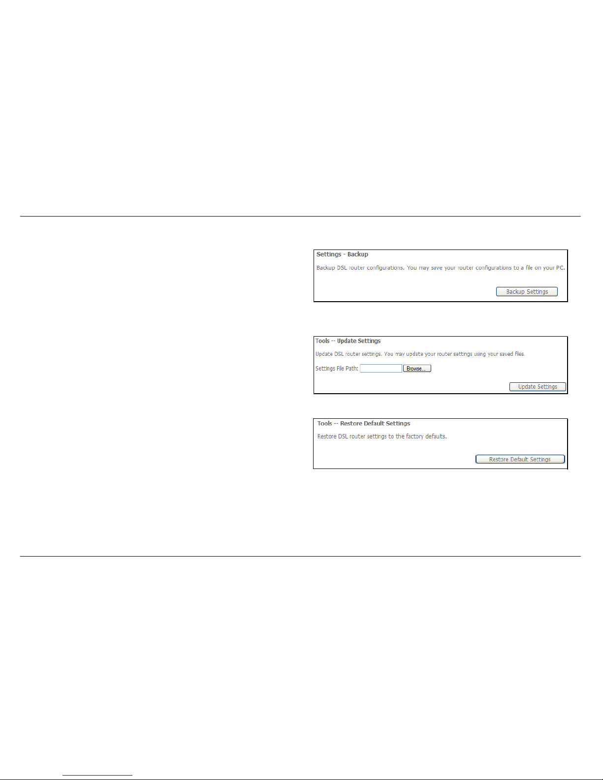
Settings – Backup
Click Backup Settings to save a backup file on the PC.
Settings – Update
Click Browse to select a file and click the Update Settings button to
update the Router settings.
Settings – Restore Default
Click the Restore Default Settings button to reset your Router back to
the factory default settings including IP settings (192.168.1.1) and
Administrator password (admin).
Page 71
Section 3 – Configuration
D-Link DSL-2542B User Manual
71
System Log
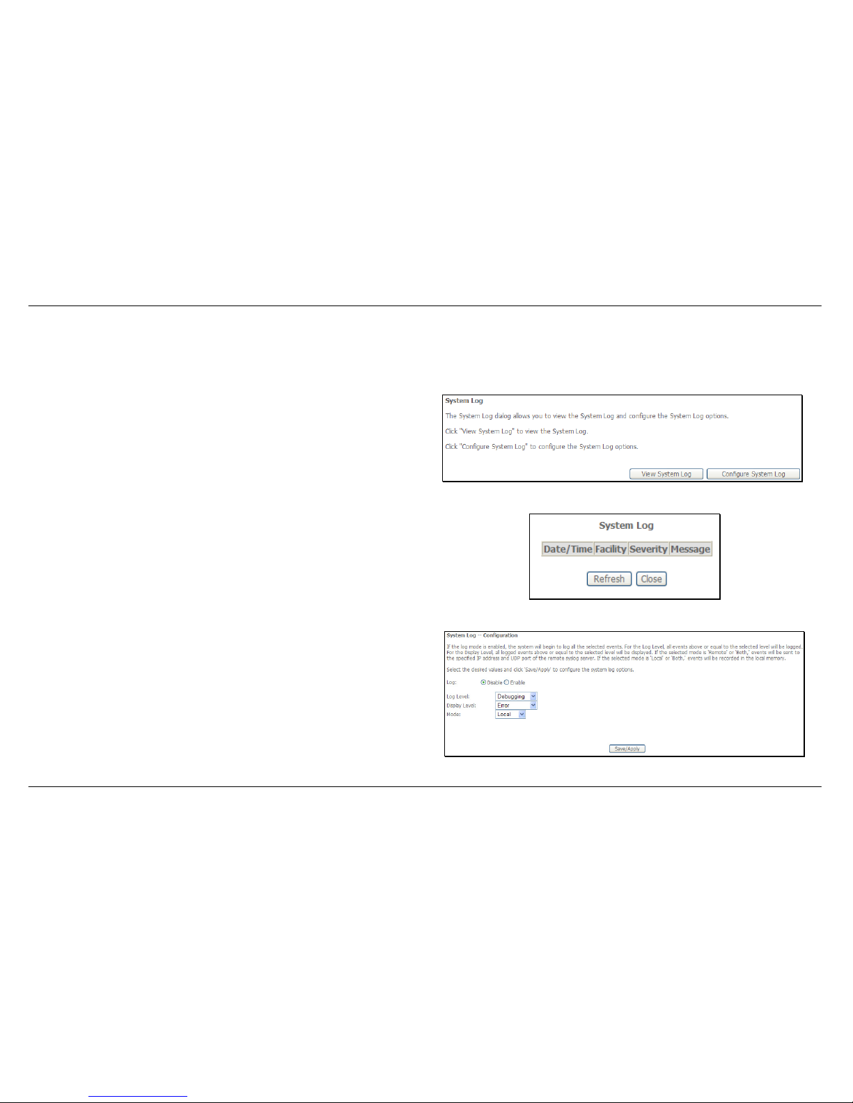
These windows allow you to view the System Log and configure the System Log options. To access the System Log window, click the System Log
button in the Management directory.
Click the View System Log button to view the System Log.
Click the Configure System Log button to configure the System Log
options.
System Log – View System Log
In the System Log window, click on the Refresh button to refresh the
system log settings.
System Log – Configuration
The system log displays chronological event log data. The event log can
be read from the local host or sent to a System Log server. The available
event severity levels are: Emergency, Alert, Critical, Error, Warning,
Notice, Informational, and Debugging.
This window allows you to log selected events. When you are finished,
click the Save/Apply button.
Page 72
Section 3 – Configuration
D-Link DSL-2542B User Manual
72
TR-069 Client
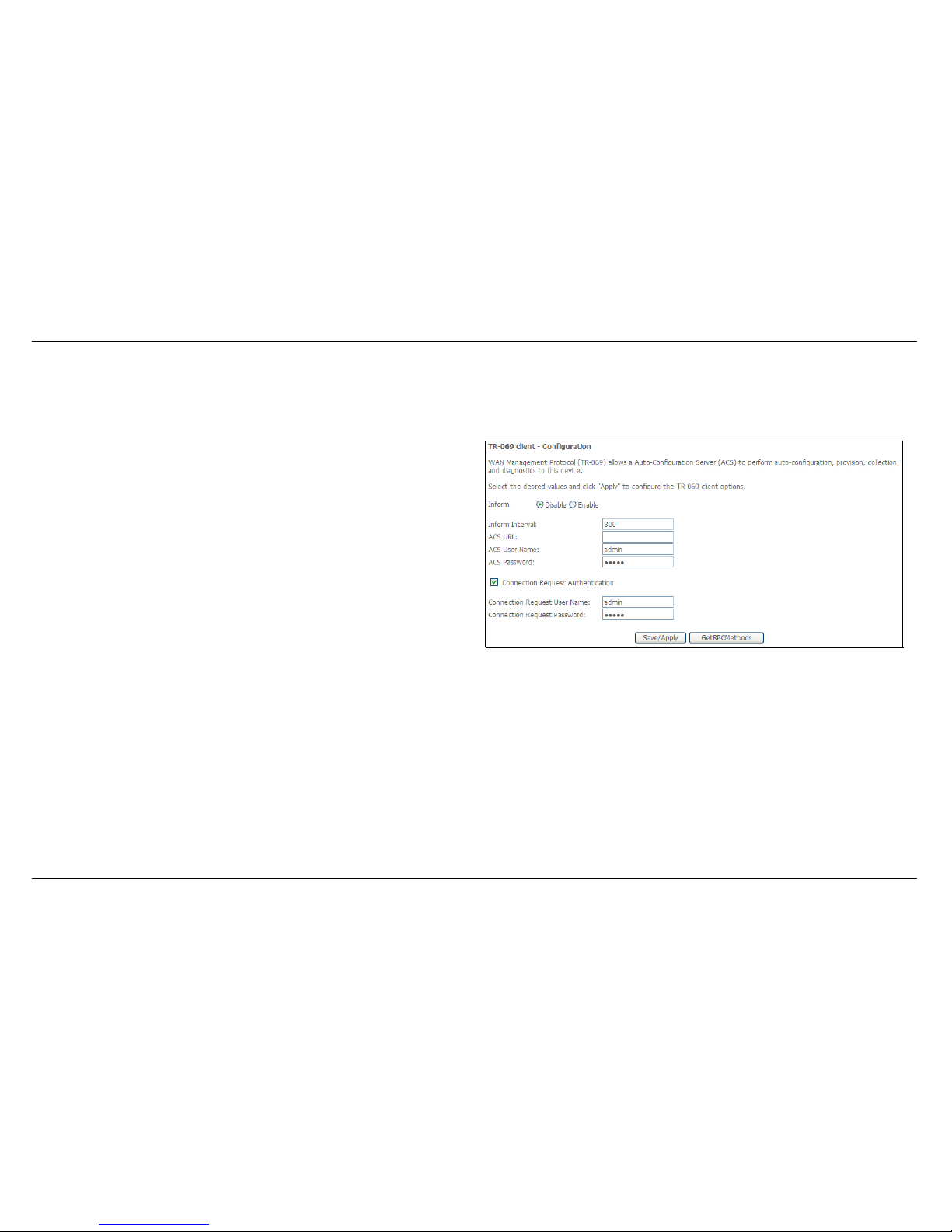
To access the TR-069 client – Configuration window, click the TR-069 Client button in the Management directory.
TR-069 (WAN Management Protocol) allows the remote server to connect
to the device and configure the device.
Click Enable under Inform, and enter the information of ACS URL,
username and password.
When you are finished, click the Save/Apply button.
Page 73
Section 3 – Configuration
D-Link DSL-2542B User Manual
73
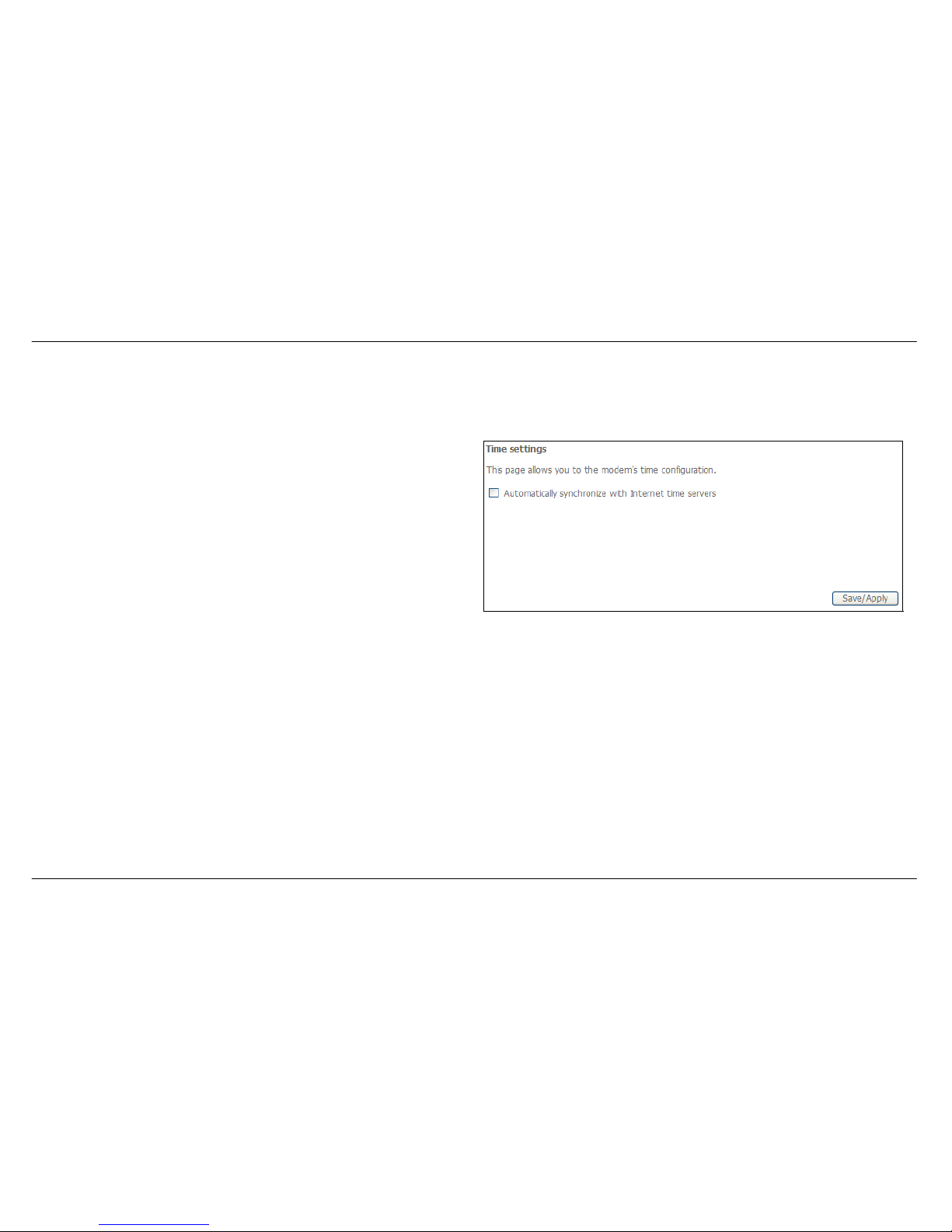
Internet Time
To access the Time settings window, click the Internet Time button in the Management directory.
This window allows you to set the Router’s time configuration. When you
are finished, click the Save/Apply button.
Page 74
Section 3 – Configuration
D-Link DSL-2542B User Manual
74
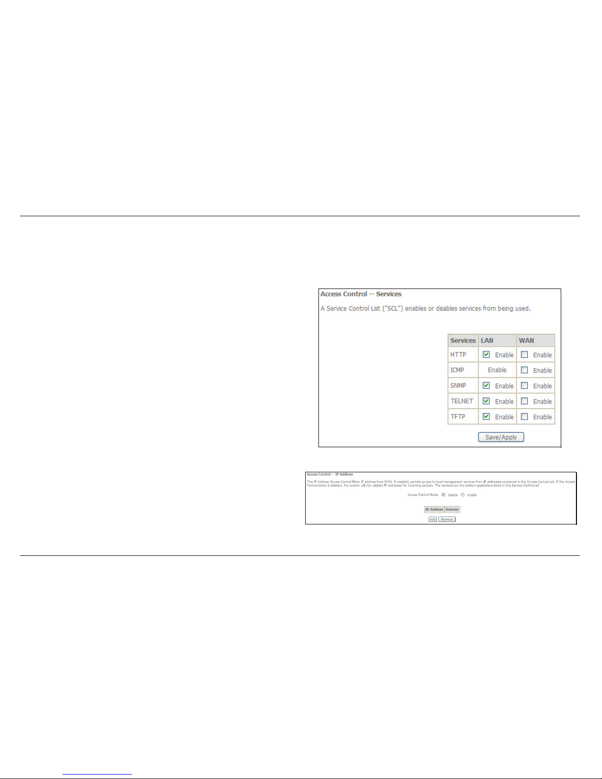
Access Control
To access the Access Control windows, click the Access Control button in the Management directory.
Access Control – Services
Enable or disable the desired LAN services. When you are finished, click
the Save/Apply button.
Access Control – IP Address
This window allows you to enable or disable Access Control Mode. To
add an IP address management station, click the Add button.
Page 75
Section 3 – Configuration
D-Link DSL-2542B User Manual
75
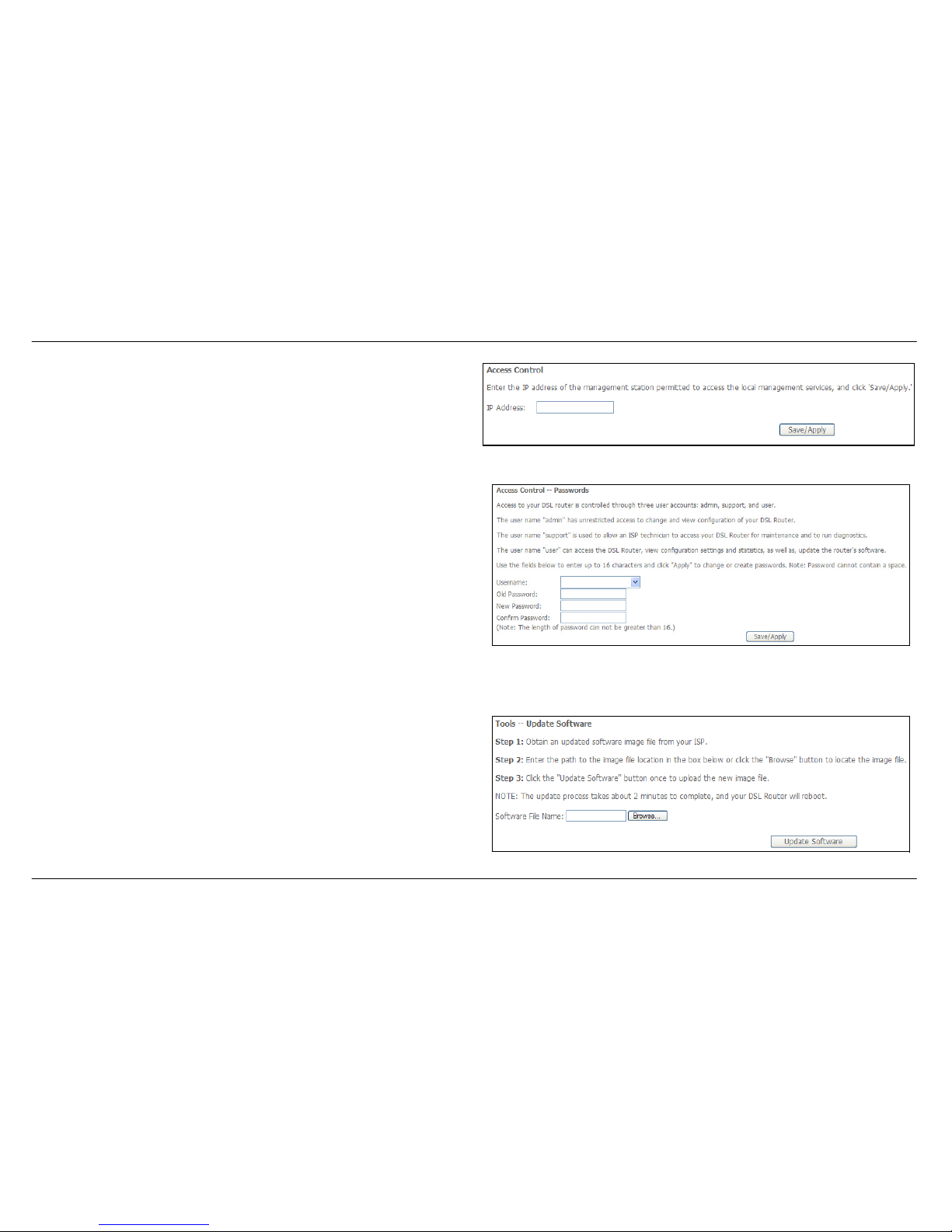
Enter the IP address of the management station permitted to access the
local management services. When you are finished, click the Save/Apply
button.
Access Control – Passwords
This window allows you to change the password on the Router. When
you are finished, click the Save/Apply button.
Update Software
To access the Update Software window, click the Update Software link in the Management directory.
This window allows you to update the Router’s software. Click the
Browse button to navigate to the location where the updated software file
is located. Once you have located the file click the Update Software
button to update the software on the Router.
Page 76
Section 3 – Configuration
D-Link DSL-2542B User Manual
76
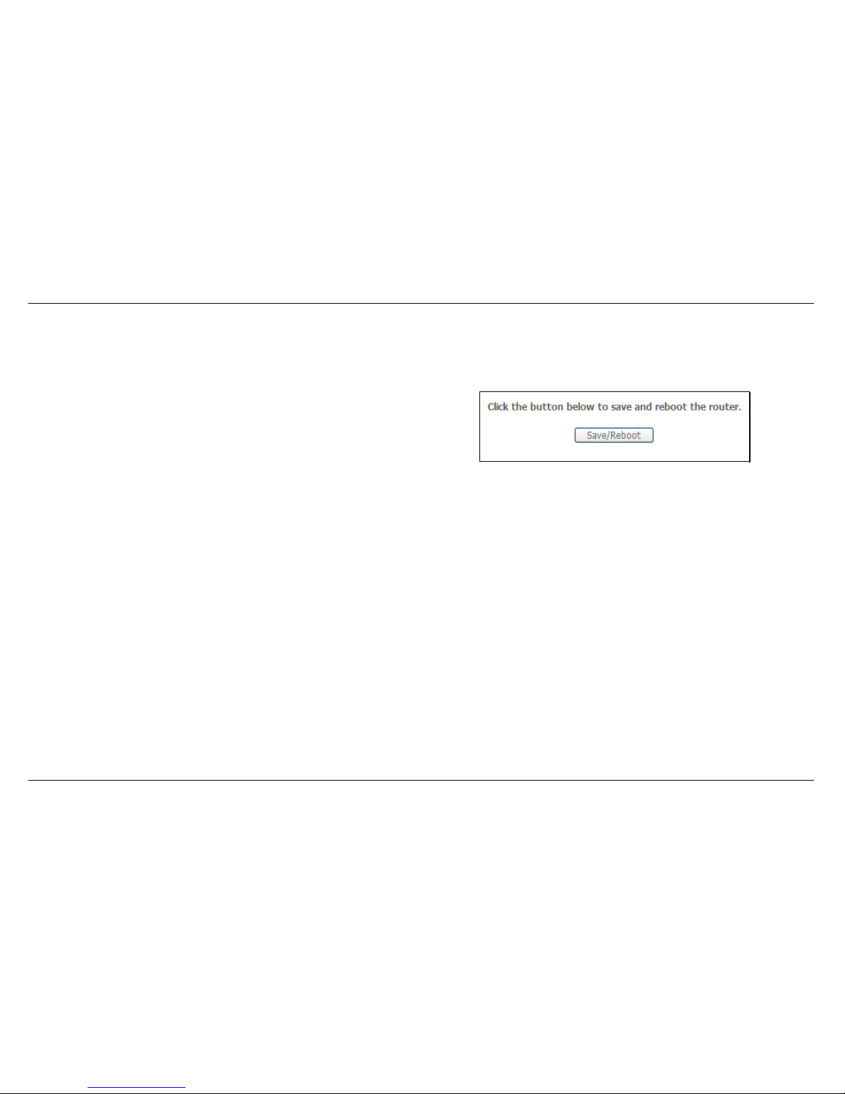
Save/Reboot
To access this window, click the Save/Reboot link in the Management directory.
To save your settings and reboot the system, click the Save/Reboot
button.
Page 77

Appendix A – Troubleshooting
D-Link DSL-2542B User Manual
77
Troubleshooting
This chapter provides solutions to problems that might occur during the installation and operation of the DSL-2542B. Read the following
descriptions if you are having problems. (The examples below are illustrated in Windows® XP. If you have a different operating system, the
screenshots on your computer will look similar to the following examples.)
1. How do I configure my DSL-2542B Router without the CD-ROM?
• Connect your PC to the Router using an Ethernet cable.
• Open a web browser and enter the address http://192.168.1.1
• The default username is ‘admin’ and the default password is ‘admin’.
• If you have changed the password and cannot remember it, you will need to reset the Router to the factory default setting (see question 2),
which will set the password back to ‘admin’.
Note: Please refer to the next section “Networking Basics” to check your PC’s IP configuration if you can’t see the login windows.
2. How do I reset my Router to the factory default settings?
• Ensure the Router is powered on.
• Press and hold the reset button on the back of the device for approximately 5 to 8 seconds.
• This process should take around 1 to 2 minutes.
Note: Resetting the Router to the factory default settings will erase the current configuration settings. To reconfigure your settings, login to the Router as
outlined in question 1, then run the Quick Setup wizard.
Page 78

Appendix A – Troubleshooting
D-Link DSL-2542B User Manual
78
3. What can I do if my Router is not working correctly?
There are a few quick steps you can take to try and resolve any issues:
• Follow the directions in Question 2 to reset the Router.
• Check that all the cables are firmly connected at both ends.
• Check the LEDs on the front of the Router. The Power indicator should be on, the Status indicator should flash, and the DSL and LAN
indicators should be on as well.
• Please ensure that the settings in the Web-based configuration manager, e.g. ISP username and password, are the same as the settings
that have been provided by your ISP.
4. Why can’t I get an Internet connection?
For ADSL ISP users, please contact your ISP to make sure the service has been enabled/connected by your ISP and that your ISP username and
password are correct.
5. What can I do if my Router can’t be detected by running the installation CD?
• Ensure the Router is powered on.
• Check that all the cables are firmly connected at both ends and all LEDs are working correctly.
• Ensure only one network interface card on your PC is activated.
• Click on Start > Control Panel > Security Center to disable the firewall.
Note: There is a potential security issue if the firewall is disabled on your PC. Please remember to turn it back on once you have finished the whole
installation procedure. This will enable you to surf the Internet without any problems.
Page 79
Appendix B - Networking Basics
D-Link DSL-2542B User Manual
79
Networking Basics
Check Your IP Address
After you install your new D-Link adapter, by default, the TCP/IP settings should be set to obtain an IP address from a DHCP server (i.e. wireless
router) automatically. To verify your IP address, please follow the steps below.
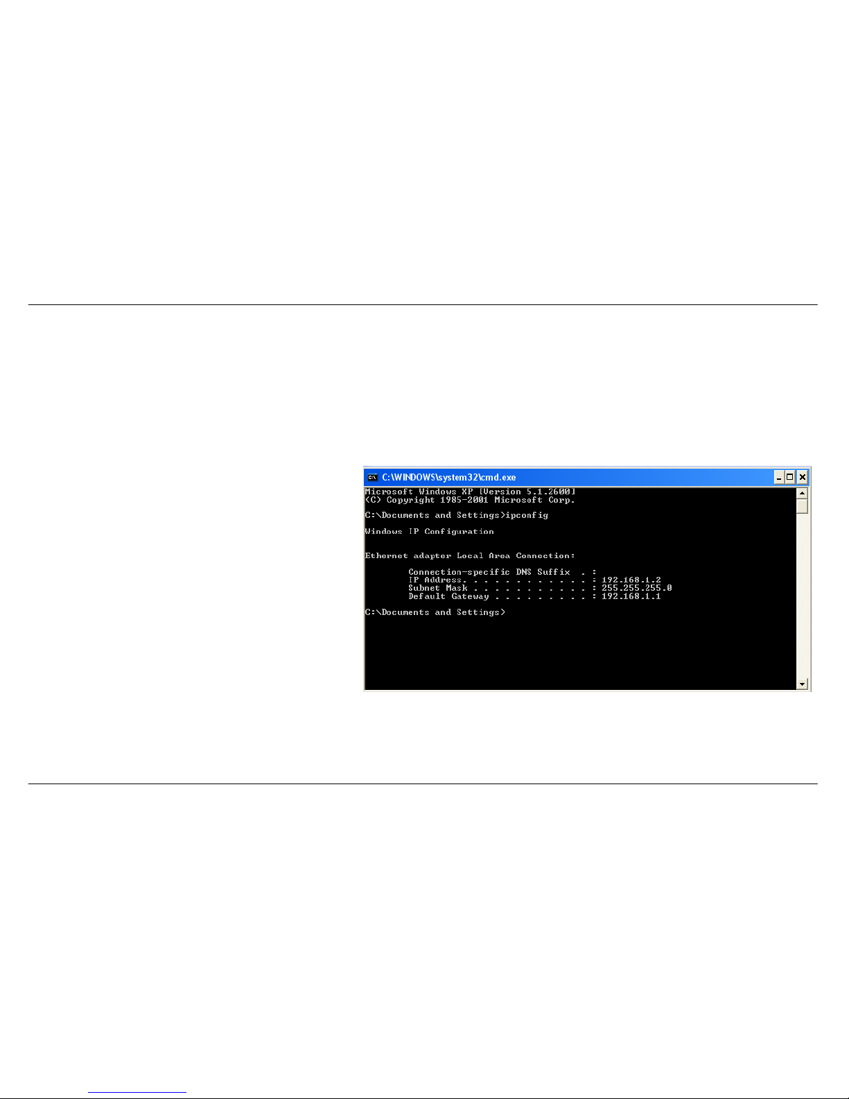
Click on Start Æ Run. In the run box type cmd and click on the OK button.
At the prompt, type ipconfig and press Enter.
This will display the IP address, subnet mask and the default
gateway of your adapter.
If the address is 0.0.0.0, check your adapter installation,
security settings and the settings on your router. Some
firewall software programs may block a DHCP request on
newly installed adapters.
If you are connecting to a wireless network at a hotspot (e.g.
hotel, coffee shop, airport), please contact an employee or
administrator to verify their wireless network settings.
Page 80
Appendix B - Networking Basics
D-Link DSL-2542B User Manual
80
Statically Assigning an IP Address
If you are not using a DHCP capable gateway/router, or you need to assign a static IP address, please follow the steps below:
Step 1
Windows® XP - Click on Start > Control Panel > Network Connections.
Windows® 2000 - From the desktop, right-click on the My Network Places > Properties.
Step 2
Right-click on the Local Area Connection which represents your D-Link network adapter and select Properties.
Step 3
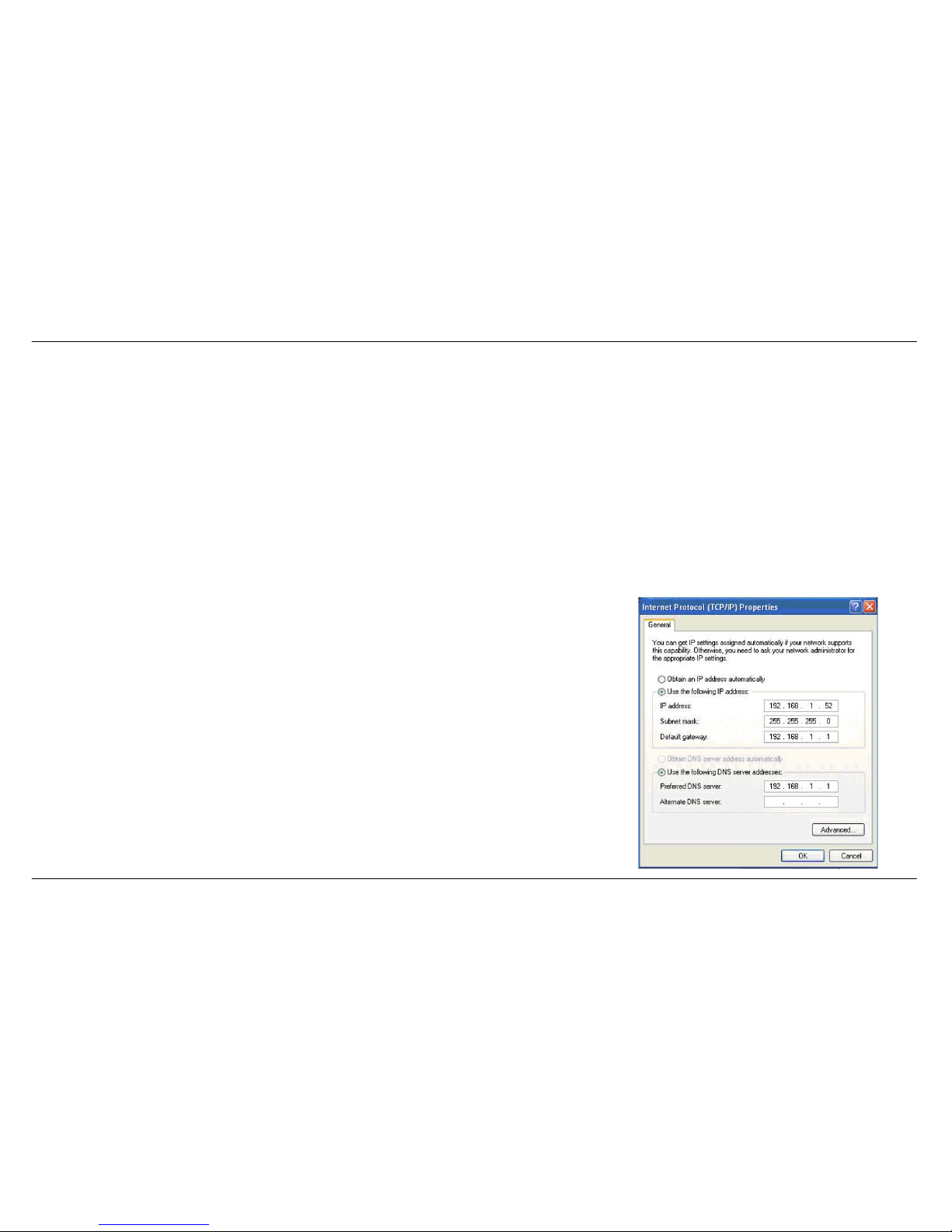
Highlight Internet Protocol (TCP/IP) and click on the Properties.
Step 4
Click on the Use the following IP address and enter an IP address that is on the same subnet as
your network or the LAN IP address on your router.
Example: If the router’s LAN IP address is 192.168.1.1, make your IP address 192.168.1.X where X
is a number between 2 and 254. Make sure that the number you choose is not in use on the
network. Set the Default Gateway to be the same as the LAN IP address of your router
(192.168.1.1).
Set the Primary DNS to be the same as the LAN IP address of your router (192.168.1.1). The
Secondary DNS is not needed or you may enter a DNS server from your ISP.
Step 5
Click on the OK button twice to save your settings.
Page 81

Appendix C - Technical Specifications
D-Link DSL-2542B User Manual
81
Technical Specifications
ADSL Standards
• ANSI T1.413 Issue 2
• ITU G.992.1 (G.dmt) Annex A
• ITU G.992.2 (G.lite) Annex A
• ITU G.994.1 (G.hs)
ADSL2 Standards
• ITU G.992.3 (G.dmt.bis) Annex A/L/M
• ITU G.992.4 (G.lite.bis) Annex A
ADSL2+ Standards
• ITU G.992.5 Annex A/M
Protocols
• IEEE 802.1d Spanning
Tree
• TCP/UDP
• ARP
• RARP
• ICMP
• RFC1058 RIP v1
• RFC1213 SNMP v1 & v2c
• RFC1334 PAP
• RFC1389 RIP v2
• RFC1577 Classical IP over
ATM
• RFC1483/2684
Multiprotocol
Encapsulation over ATM
Adaptation Layer 5 (AAL5)
• RFC1661 Point to Point
Protocol
• RFC1994 CHAP
• RFC2131 DHCP Client /
DHCP Server
• RFC2364 PPP over ATM
• RFC2516 PPP over
Ethernet
Data Transfer Rate
• G.dmt full rate downstream: up to 8 Mbps / upstream: up to 1
Mbps
• G.lite: ADSL downstream up to 1.5 Mbps / upstream up to 512
Kbps
• G.dmt.bis full rate downstream: up to 12 Mbps / upstream: up to
1 Mbps
• ADSL full rate downstream: up to 24 Mbps / upstream: up to 1
Mbps
Media Interface
• ADSL interface: RJ-11 connector for connection to 24/26 AWG
twisted pair telephone line
• LAN interface: RJ-45 port for 10/100BASE-T Ethernet
connection
 Loading...