

Page 1

FCC Class B Warning
This equipment has been tested and found to comply with the limits for a Class B digital device,
pursuant to Part 15 of the FCC Rules. These limits are designed to provide reasonable protection
against harmful interference in a residential installation. This equipment generates, uses and can
radiate radio frequency energy and, if not installed and used in accordance with the instructions,
may cause harmful interference to radio communications. However, there is no guarantee that
interference will not occur in a particular installation. If this equipment does cause harmful
interference to radio or television reception, which can be determined by turning the equipment off
and on, the user is encouraged to try to correct the interference by one or more of the following
measures:
Reorient or relocate the receiving antenna.
Increase the separation between the equipment and the receiver.
Connect the equipment into an outlet on a circuit different from that to which the receiver is
connected.
Consult the dealer or an experienced radio/TV technician for help.
Shielded interface cables must be used in order to comply with emission limits.
Changes or modifications not expressly approved by user authority to operate this equipment.
Trademarks
Copyright D-Link Corporation.
Contents subject to change without prior notice.
D-Link is a registered trademark of D-Link Corporation/
D-Link Systems, Inc.
All other trademarks belong to their respective proprietors.
Copyright Statement
No part of this publication may be reproduced in any form or by any means or used to make any
derivative such as translation, transformation, or adaptation without permission from D-Link
Corporation/D-Link Systems Inc., as stipulated by the United States Copyright Act of 1976.
Rev. 06 (March 2001)
6DSH8.....06
Printed In Taiwan
Page 2

Limited Warranty
Hardware:
D-Link warrants each of its hardware products to be free from defects in workmanship and
materials under normal use and service for a period commencing on the date of purchase from
D-Link or its Authorized Reseller and extending for the length of time stipulated by the Authorized
Reseller or D-Link Branch Office nearest to the place of purchase.
This Warranty applies on the condition that the product Registration Card is filled out and returned
to a D-Link office within ninety (90) days of purchase. A list of D-Link offices is provided at the
back of this manual, together with a copy of the Registration Card.
If the product proves defective within the applicable warranty period, D-Link will provide repair or
replacement of the product. D-Link shall have the sole discretion whether to repair or replace, and
replacement product may be new or reconditioned. Replacement product shall be of equivalent or
better specifications, relative to the defective product, but need not be identical. Any product or
part repaired by D-Link pursuant to this warranty shall have a warranty period of not less than 90
days, from date of such repair, irrespective of any earlier expiration of original warranty period.
When D-Link provides replacement, then the defective product becomes the property of D-Link.
Warranty service may be obtained by contacting a D-Link office within the applicable warranty
period, and requesting a Return Material Authorization (RMA) number. If a Registration Card for
the product in question has not been returned to D-Link, then a proof of purchase (such as a copy of
the dated purchase invoice) must be provided. If Purchaser's circumstances require special
handling of warranty correction, then at the time of requesting RMA number, Purchaser may also
propose special procedure as may be suitable to the case.
After an RMA number is issued, the defective product must be packaged securely in the original or
other suitable shipping package to ensure that it will not be damaged in transit, and the RMA
number must be prominently marked on the outside of the package. The package must be mailed or
otherwise shipped to D-Link with all costs of mailing/shipping/insurance prepaid. D-Link shall
never be responsible for any software, firmware, information, or memory data of Purchaser
contained in, stored on, or integrated with any product returned to D-Link pursuant to this
warranty.
Any package returned to D-Link without an RMA number will be rejected and shipped back to
Purchaser at Purchaser's expense, and D-Link reserves the right in such a case to levy a reasonable
handling charge in addition mailing or shipping costs.
Warranty Period
For warranty in your region, please check with your local D-Link office and authorized agents as
warranty periods may vary from region to region.
The warranty for power supplies and power adapters is one year.
Registration and Warranty Service
The product's Registration Card, provided at the back of this manual, must be sent to a D-Link
office. To obtain an RMA number for warranty service as to a hardware product, or to obtain
warranty service as to a software product, contact the D-Link office nearest you. An
address/telephone/fax/e-mail/Web site list of D-Link offices is provided in the back of this manual.
Page 3

WARRANTIES EXCLUSIVE
IF THE D-LINK PRODUCT DOES NOT OPERATE AS WARRANTED ABOVE, THE
CUSTOMER'S SOLE REMEDY SHALL BE, AT D-LINK'S OPTION, REPAIR OR
REPLACEMENT. THE FOREGOING WARRANTIES AND REMEDIES ARE EXCLUSIVE AND
ARE IN LIEU OF ALL OTHER WARRANTIES, EXPRESSED OR IMPLIED, EITHER IN FACT
OR BY OPERATION OF LAW, STATUTORY OR OTHERWISE, INCLUDING WARRANTIES OF
MERCHANTABILITY AND FITNESS FOR A PARTICULAR PURPOSE. D-LINK NEITHER
ASSUMES NOR AUTHORIZES ANY OTHER PERSON TO ASSUME FOR IT ANY OTHER
LIABILITY IN CONNECTION WITH THE SALE, INSTALLATION MAINTENANCE OR USE OF
D-LINK'S PRODUCTS.
D-LINK SHALL NOT BE LIABLE UNDER THIS WARRANTY IF ITS TESTING AND
EXAMINATION DISCLOSE THAT THE ALLEGED DEFECT IN THE PRODUCT DOES NOT
EXIST OR WAS CAUSED BY THE CUSTOMER'S OR ANY THIRD PERSON'S MISUSE,
NEGLECT, IMPROPER INSTALLATION OR TESTING, UNAUTHORIZED ATTEMPTS TO
REPAIR, OR ANY OTHER CAUSE BEYOND THE RANGE OF THE INTENDED USE, OR BY
ACCIDENT, FIRE, LIGHTNING OR OTHER HAZARD.
LIMITATION OF LIABILITY
IN NO EVENT WILL D-LINK BE LIABLE FOR ANY DAMAGES, INCLUDING LOSS OF DATA,
LOSS OF PROFITS, COST OF COVER OR OTHER INCIDENTAL, CONSEQUENTIAL OR
INDIRECT DAMAGES ARISING OUT THE INSTALLATION, MAINTENANCE, USE,
PERFORMANCE, FAILURE OR INTERRUPTION OF A D- LINK PRODUCT, HOWEVER
CAUSED AND ON ANY THEORY OF LIABILITY. THIS LIMITATION WILL APPLY EVEN IF DLINK HAS BEEN ADVISED OF THE POSSIBILITY OF SUCH DAMAGE.
IF YOU PURCHASED A D-LINK PRODUCT IN THE UNITED STATES, SOME STATES DO NOT
ALLOW THE LIMITATION OR EXCLUSION OF LIABILITY FOR INCIDENTAL OR
CONSEQUENTIAL DAMAGES, SO THE ABOVE LIMITATION MAY NOT APPLY TO YOU.
Page 4

Product Description
The dual-speed standalone Ethernet/Fast Ethernet hub is designed to
allow easy migration and integration between 10Mbps Ethernet and
100Mbps Fast Ethernet, while providing flexibility in cable
connections.
The device can operate with both IEEE 802.3 10BASE-T connections
(twisted-pair Ethernet operating at 10 megabits per second) and
IEEE 802.3u 100BASE-TX connections (twisted-pair Fast Ethernet
operating at 100 megabits per second). All of the twisted-pair ports
support Auto-Negotiation (NWay), allowing the hub to automatically
detect the speed of a network connection.
The hub has 8 ports and can have a single uplink connection to
another 100BASE-TX Class II Fast Ethernet repeater (hub or hub
stack).
On the hub, the 10Mbps and 100Mbps segments are separate and do
not intercommunicate. The device contains a built-in switch, making
it possible to transparently bridge between the 10Mbps and 100Mbps
segments.
Features
♦ Compatible with the IEEE 802.3 10BASE-T Ethernet and 802.3u
100BASE-TX Fast Ethernet industry standards for
interoperability with other Ethernet/Fast Ethernet network
devices
♦ Eight NWay RJ-45 ports for connecting stations to the network
♦ Built-in switching function supports bridging between 10Mbps
and 100Mbps segments
♦ LED indicators for power, collision, link, network activity, and
operating speed (10 or 100 Mbps)
♦ Auto-partitioning for network protection
Page 5
♦ Data collision detection and handling
♦ Preamble regeneration, signal retiming
♦ Uplink port allows easy linking of two Fast Ethernet or four
Ethernet hub stacks to further expand your network
♦ External linear power adapter featured (output 7.5V/1A)
♦ Simple Plug and Play installation
♦ Compact size and light weight, ideal for SOHO, cubicle LANs
Unpacking
The carton should contain the following items:
♦ One dual-speed standalone hub
♦ One external power adapter
♦ One pair of mounting brackets
♦ This User's Guide
Inspect the hub and all accompanying items. If any item is damaged
or missing, report the problem immediately to your networking
product dealer.
External Components
Front Panel
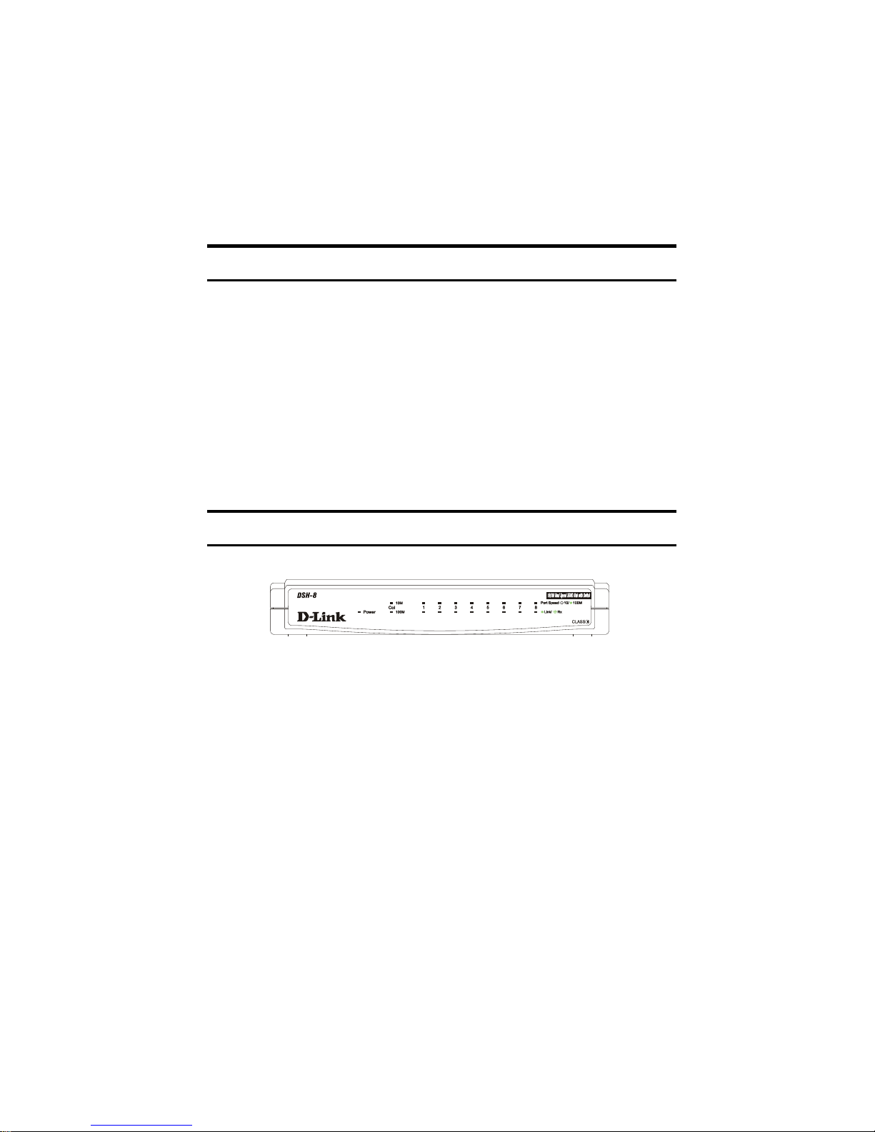
♦ Power Indicator This LED indicator lights green when the hub
is receiving power; otherwise, it is off.
Page 6
♦ Collision Indicators (10M/100M) These LEDs indicate data
collisions on the respective 10Mbps Ethernet or 100Mbps Fast
Ethernet segments connected to the hub. (If several hubs are linked
together, all of them should detect and indicate the same collision,
since collisions span the entire network segment.) Whenever a
collision is detected, the respective collision indicator will briefly
blink amber.
♦ Link (steady green) This LED will be lit when the port is
connected to a powered Ethernet or Fast Ethernet station. If the
station to which the hub is connected is powered off, or if there is a
problem with the link, the LED will remain off.
♦ Receive (Rx) (blinking green) When information is received
on a port, its LED indicator will blink off briefly. Upon reception, the
data will be transmitted to all other connected ports.
♦ 10/100 Port Speed Indicators There is a port speed LED
indicator for each of the twisted-pair ports on the hub. A port speed
indicator will light green when a 100BASE-TX device is connected to
the port. It will remain dark if the port is not connected or if a
10BASE-T device is connected.
Rear Panel
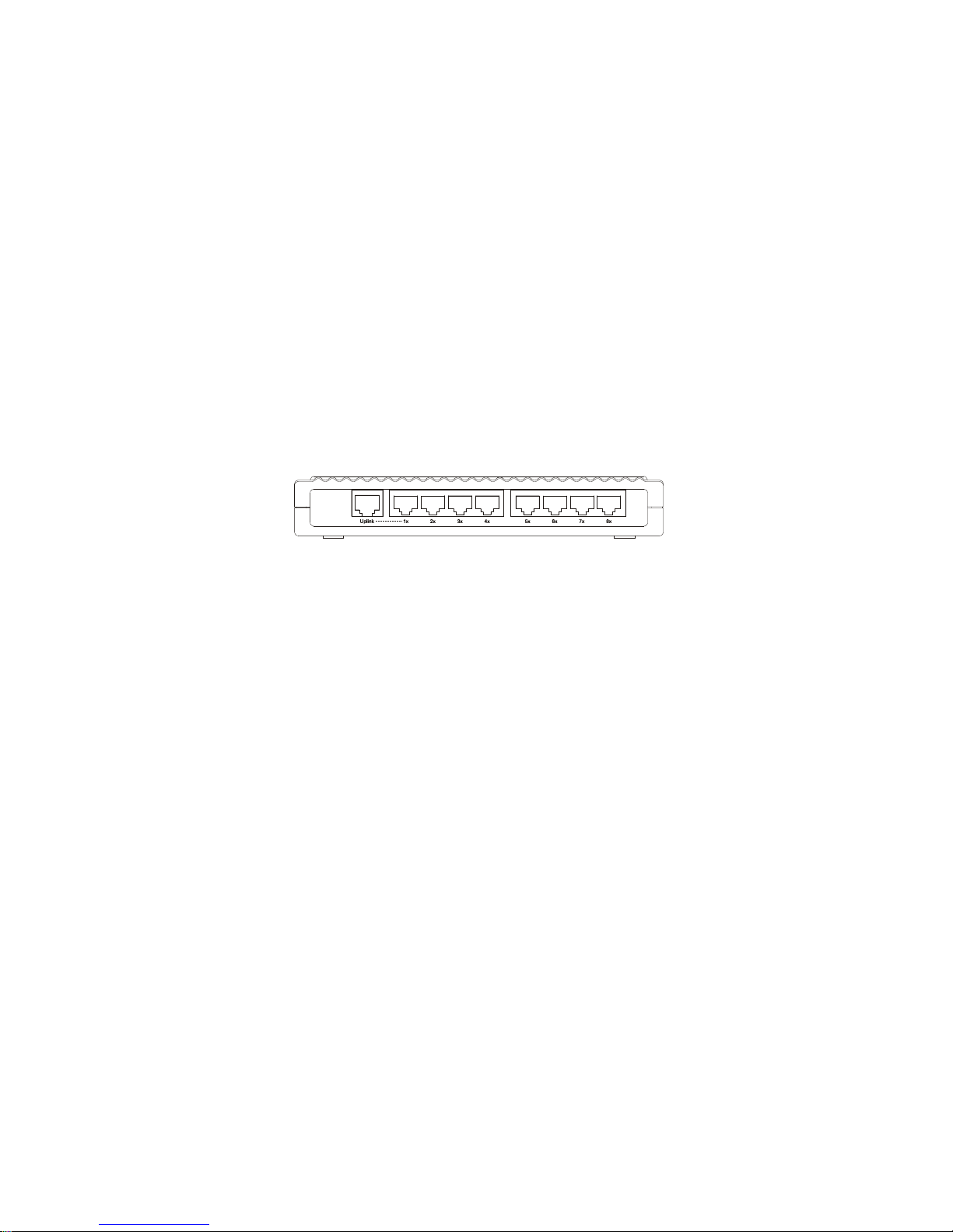
♦ Twisted-Pair Ports Use any of these ports to connect stations
to the hub. The ports are MDI-X ports, which means you can use
ordinary straight-through twisted-pair cables to connect the hub to
PCs, workstations, or servers through these ports. If you need to
connect another device with MDI-X ports such as another hub or an
Ethernet switch, you should use a crossover cable, or connect using
the Uplink port.
♦ Uplink Port The Uplink port is an MDI-II port, which means
you can connect the hub to another device with MDI-X ports using an
ordinary straight-through cable, making a crossover cable
unnecessary. Port 1 and the Uplink port are really the same port,
Page 7
except that their pinouts are different. Do not use both Port 1
and the Uplink port at the same time.
Right-hand Side Panel
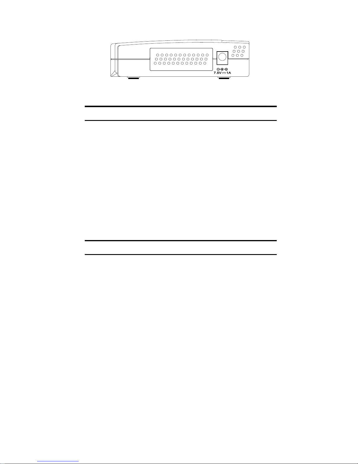
♦ AC Power Adapter Connector For the external power supply.
Installing the Hub
Install the hub in a fairly cool and dry place. See Specifications for the
acceptable temperature and humidity operating ranges.
Install the hub in a site free from strong electromagnetic field
generators (such as motors), vibration, dust, and direct exposure to
sunlight.
Leave at least 10 cm of space at the front and rear of the hub for
ventilation.
Install the hub on a sturdy, level surface that can support its weight.
When installing the hub on a level surface, attach the rubber feet to
the bottom of the device. The rubber feet cushion the hub and protect
the hub case from scratches and prevent it from scratching other
surfaces.
Making Connections
Connectivity Rules
Ethernet (10Mbps) networks need to respect the following
connectivity rules:
Page 8

The maximum length of a twisted-pair cable segment is 100
meters. Cabling should be Category 3 or better.
Between any two end-stations in a collision domain, there may be
up to five cable segments and four intermediate repeaters (hubs,
hub stacks, or other repeaters).
If there is a path between any two end-stations containing five
segments and four repeaters, then at least two of the cable
segments must be point-to-point link segments (e.g., 10BASE-T,
10BASE-FL), while the remaining segments may be populated
(mixing) segments (e.g., 10BASE-2 or 10BASE-5).
Fast Ethernet (100Mbps) networks need to respect the following
connectivity rules:
The maximum length of a twisted-pair segment (that is, the
distance between a port in the hub to a single-address network
device such as a PC, server, or Ethernet switch) is 100 meters.
Cabling and other wiring should be certified as Category 5 or
shielded twisted pair (STP).
The maximum diameter in a collision domain is about 205 meters
using two Class II hubs (or hub stacks).
Between any two end-stations in a collision domain, there may be
up to three cable segments and two Class II hubs or hub stacks.
Hub to End-Station Connection
After the hub properly installed, it can support up to eight end-station
connections. Fast Ethernet connection requires either a Category 5
UTP cable or an STP cable. These cables can be up to 100 meters
long.
Ethernet connection requires a Category 3 or better UTP cable. It is
recommended that you use Category 5 cabling for all connections, in
order to make it easier to transition all stations to 100Mbps.
You can connect any combination of PCs, servers, and other singleaddress network devices to the eight twisted-pair ports using
straight-through twisted-pair cables. These cables should not be
Page 9
crossed over.
When connecting a PC or a server, the system being connected should
have an Ethernet or Fast Ethernet network interface card with a
twisted-pair port.
Hub-to-Hub Uplink
You can link two hubs or a hub with a hub stack by using any of the
twisted-pair ports or the Uplink port. Linking hubs using ordinary
twisted-pair ports requires crossover twisted-pair cables; linking
using one ordinary twisted-pair port and the Uplink port requires an
ordinary straight-through twisted-pair cable. The Uplink port is
shared with Port 1, and you should not use both Port 1 and the
Uplink port at the same time.
When connecting two hubs or a hub with a hub stack in this fashion,
the maximum distance between any two end-stations in a collision
domain is 205 meters. If each link between the hub and an endstation is 100 meters, then the hub-to-hub connection is limited to 5
meters. However, if the longest hub-to-end-station connection is less
than 100 meters, then the hub-to-hub connection can be up to 100
meters long as long as the 205-meter total network diameter rule is
followed.
The following table describes different methods of linking hubs (or
hub stacks):
Page 10
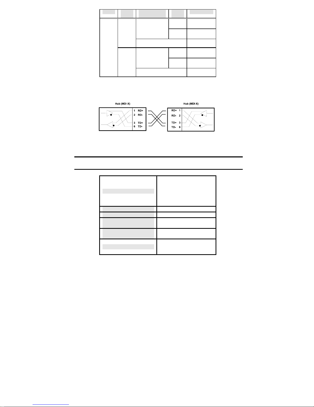
DEVICE PORT
Normal
USED
DEVICE BEING
CONNECTED
Hub or
Switch
PORT
TYPE
Normal Crossover (X)
Uplink Straight-Through (||)
CABLE TO USE
Hub Server (or PC) Straight-Through (I|)
Uplink
Server (or PC) Crossover (X)
Hub or
Switch
Normal Straight-Through (||)
Uplink Crossover (X)
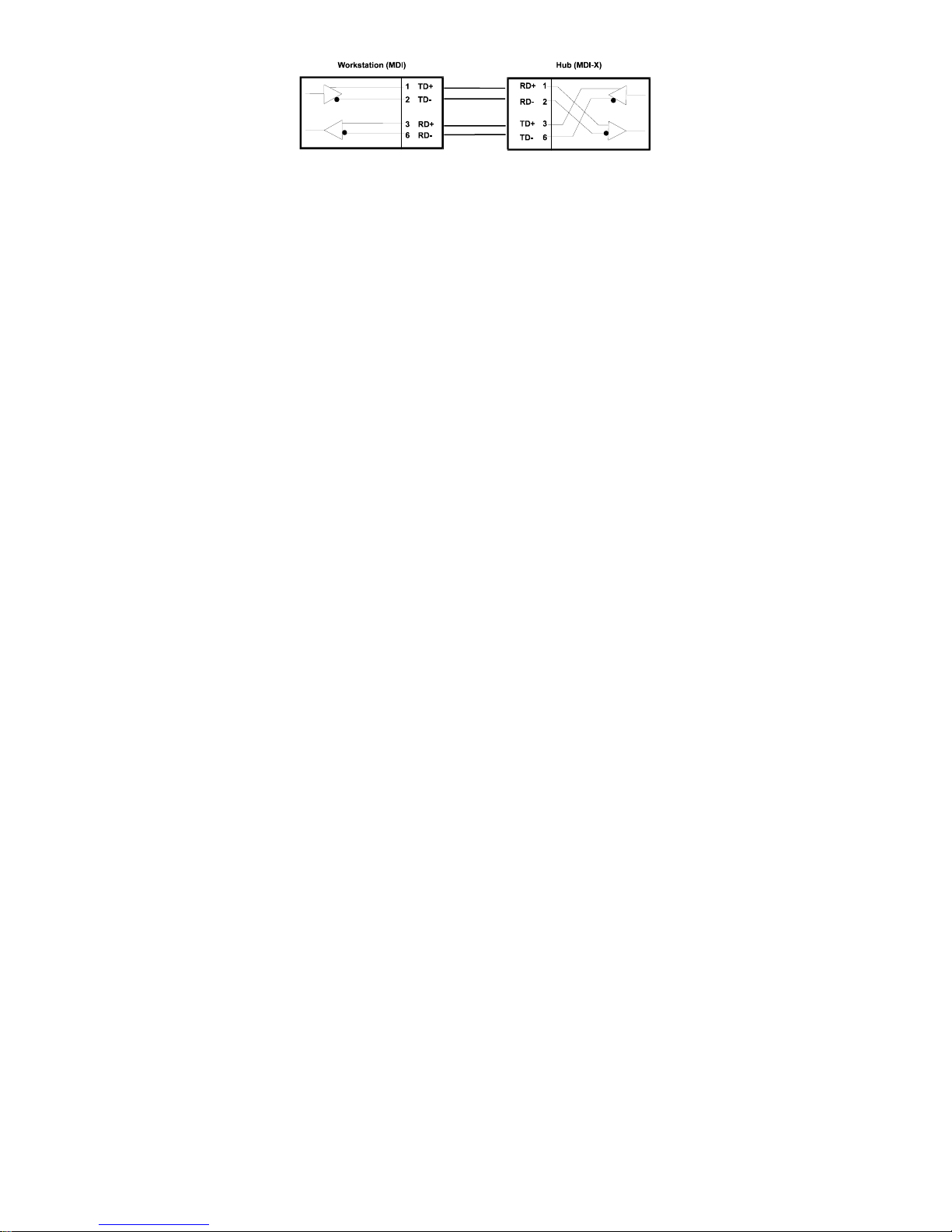
A crossover cable is a straight-through twisted-pair cable in which the
wires have been crossed. The figure below shows the pin assignments
for an Ethernet or Fast Ethernet crossover cable:
NOTE: The first twisted-pair port (Port 1) is shared with the Uplink port. If you connect a
hub to the Uplink port, then do not use Port 1.
Specifications
IEEE 802.3 10BASE-T
Ethernet repeater, IEEE
Standards Compliance
Topology Star
Protocol CSMA/CD
Network Data
Transfer Rate
Number of Ports per
Hub
Network Cables
802.3u 100BASE-TX Fast
Ethernet repeater (Class
II), ANSI X3T9.5 TwistedPair Transceiver
Ethernet: 10Mbps; Fast
Ethernet: 100Mbps
8, all dual-speed
(10/100Mbps)
10BASE-T: 2-pair UTP
Cat. 3,4,5 (100 m):
EIA/TIA-568 100-ohm
Page 11
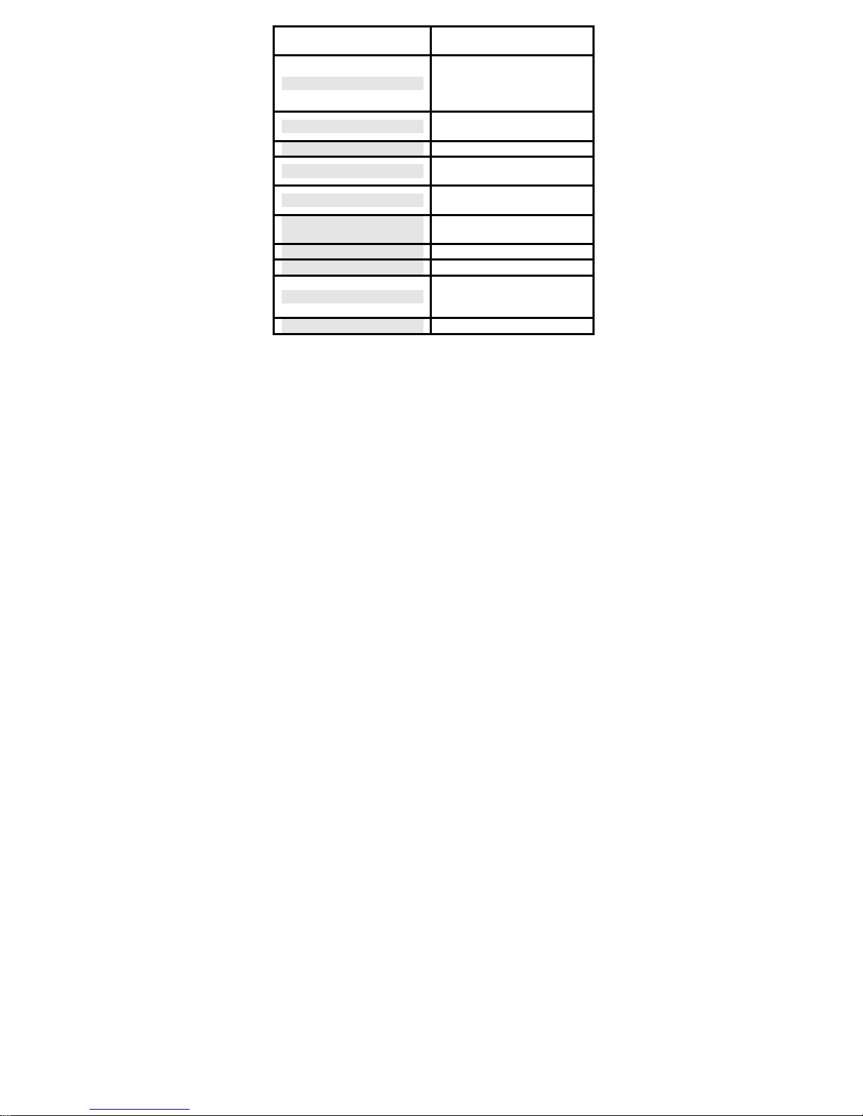
screened twisted pair
(STP) (100 m)
Power, 10Mbps collision,
LED State Indicators
100Mbps collision, Link/
Receive, Speed
(10/100Mbps)
Power Supply
External power adapter
(output: 7.5V/1A)
Power Consumption 6 watts
Dimensions
Weight
Operating
190 mm (W) x 30.9 mm (H)
x 116.8 mm (D)
400 g (w/o external power
adapter)
0º to 55º C (32º-131º F)
Temperature
Storage Temperature -25º to 55º C (-13º-131º F)
Humidity 5%-95% non-condensing
FCC Class B, CE Mark
Emissions
Class B, BSMI Class B,
C-Tick
Safety CUL/CUL, TUV/GS
Page 12

Offices
AUSTRALIA D-Link Australasia
Unit 16, 390 Eastern Valley Way, Roseville,
NSW 2069 Australia
TEL: 61-2-9417-7100 FAX: 61-2-9417-1077
TOLL FREE (Australia): 1800 177 100 TOLL FREE (New Zealand): 0800-900900
URL: www.dlink.com.au E-MAIL: [email protected] & [email protected]
CANADA D-Link Canada
2180 Winston Park Drive, Oakville, Ontario, L6H 5W1 Canada
TEL: 1-905-829-5033 FAX: 1-905-829-5095 BBS: 1-965-279-8732 TOLL FREE: 1-800-354-6522
URL: www.dlink.ca FTP: ftp.dlinknet.com E-MAIL: [email protected]
CHILE D-Link South America
Isidora Goyeechea 2934 of 702, Las Condes, Santiago, Chile
TEL : 56-2-232-3185 FAX: 56-2-232-0923 URL: www.dlink.cl
E-MAIL: [email protected] & [email protected]
DENMARK D-Link Denmark
Naverland 2, DK-2600 Glostrup, Copenhagen, Denmark
TEL:45-43-969040 FAX:45-43-424347 URL: www.dlink.dk E-MAIL: [email protected]
EGYPT D-Link Middle East
7 Assem Ebn Sabet Street, Heliopolis, Cairo, Egypt
TEL: 202-245-6176 FAX: 202-245-6192
URL: www.dlink-me.com E-MAIL: [email protected] & [email protected]
FINLAND D-Link Finland
Tulli-ja Pakkahuone, Katajanokanlaituri 5, Fin – 00160 Helsinki
TEL: 358-9-62291660 FAX: 358-9-62291661 URL: www.dlink-fi.com
FRANCE D-Link France
Le Florilege #2, Allee de la Fresnerie, 78330 Fontenay le Fleury, France
GERMANY D-Link Central Europe/D-Link Deutschland GmbH
Schwalbacher Strasse 74, 65760 Eschborn, Germany
TEL: 49-(0) 6196-7799-0 FAX: 49-(0) 6196-7799-300 URL: www.dlink.de
BBS: 49-(0) 6192-971199 (analog) BBS: 49-(0) 6192-971198 (ISDN)
INFO: 00800-7250-0000 (toll free) HELP: 00800-7250-4000 (toll free)
REPAIR: 00800-7250-8000 E-MAIL: [email protected]
INDIA D-Link India
Plot No.5, Kurla-Bandra Complex Rd., Off Cst Rd.,
Santacruz (E), Bombay, 400 098 India
TEL: 91-22-652-6696 FAX: 91-22-652-8914
URL: www.dlink-india.com E-MAIL: [email protected]
ITALY D-Link Mediterraneo Srl
Via Nino Bonnet n. 6/b, 20154, Milano, Italy
JAPAN D-Link Japan
10F, 8-8-15 Nishi-Gotanda, Shinagawa-ku, Tokyo 141, Japan
TEL: 81-3-5434-9678 FAX: 81-3-5434-9868 URL: www.d-link.co.jp E-MAIL: [email protected]
RUSSIA D-Link Russia
Michurinski Prospekt 49, 117607 Moscow, Russia
TEL: 7-095-737-3389 & 7-095-737-3492 FAX: 7-095-737-3390
URL: www.dlink.ru E-MAIL: [email protected]
Page 13

SINGAPORE D-Link International
1 International Business Park, #03-12 The Synergy, Singapore 609917
S. AFRICA D-Link South Africa
Unit 2, Parkside 86 Oak Avenue, Highveld Technopark Centurion, Gauteng, South Africa
SWEDEN D-Link Sweden
P. O. Box 15036, S-167 15 Bromma, Sweden
TEL: 46-(0) 8564-61900 FAX: 46-(0) 8564-61901 E-MAIL: [email protected] URL: www.dlink.se
TAIWAN D-Link Taiwan
2F, No. 119 Pao-Chung Rd, Hsin-Tien, Taipei, Taiwan
U.K. D-Link Europe
4
U.S.A. D-Link U.S.A.
53 Discovery Drive, Irvine, CA 92618, USA
TEL: 1-949-788-0805 FAX: 1-949-753-7033
BBS: 1-949-455-1779 & 1-949-455-9616 INFO: 1-800-326-1688
URL: www.dlink.com E-MAIL: [email protected] & [email protected]
th
Floor, Merit House, Edgware Road, Colindale, London NW9 5AB U.K.
TEL: 44 (0) 20-8731-5555 FAX: 44 (0) 20-8731-5511
BBS: 44 (0) 181-235-5511 URL: www.dlink.co.uk E-MAIL: [email protected]
Page 14
Register Online at http://support.dlink.com/register/
Print, type or use block letters.
Your name: Mr./Ms____________________________________________________
Organization:__________________________Dept.__________________________
Your title at organization:_______________________________________________
Telephone:________________________ Fax:______________________________
Organization's full address:_____________________________________________
Country:____________________________________________________________
Date of purchase (Month/Day/Year):______________________________________
Product Model Product Serial
No.
* Product
installed in type
of
computer (e.g.,
Compaq 486)
* Product installed in
computer serial No.
(* Applies to adapters only)
Product was purchased from:
Reseller's name:______________________________________________________
Telephone:_________________________ Fax:_____________________________
Reseller's full address:_________________________________________________
___________________________________________________________________
___________________________________________________________________
Answers to the following questions help us to support your product:
1.Where and how will the product primarily be used?
Home Office Travel Company Business Home Business Personal Use
2. How many employees work at installation site?
1 employee 2-9 10-49 50-99 100-499 500-999 1000 or more
3. What network protocol(s) does your organization use ?
XNS/IPX TCP/IP DECnet Other_____________________________
4. What network operating system(s) does your organization use ?
D-Link LANsmart Novell NetWare NetW are Lite SCO Unix/Xenix PC NFS 3Com 3+Open
Banyan Vines DECnet Pathwork Windows NT Windows NTAS W indows '95
Other__________________________________________
5. What network management program does your organization use ?
D-View HP OpenView/Windows HP OpenView/Unix SunNet Manager Novell NMS
NetView 6000 Other________________________________________
6. What network medium/media does your organization use ?
Fiber-optics Thick coax Ethernet Thin coax Ethernet 10BASE-T UTP/STP
100BASE-TX 100BASE-T4 100VGAnyLAN Other_________________
7. What applications are used on your network?
Desktop publishing Spreadsheet Word proc essing CAD/CAM
Database management Accounting Other_____________________
8. What category best describes your company?
Aerospace Engineering Education Finance Hospital Legal Insurance/Real Estate Manufacturing
Retail/Chainstore/Wholesale Government T ransportation/Utilities/Communication VAR
System house/company Other________________________________
9. Would you recommend your D-Link product to a friend?
Yes No Don't know yet
 Loading...