

Page 1
Model DP-100
Multiprotocol Ethernet
Print Server
Hardware User’s Guide
Rev. 01 (May, 1997)
6DP100H.001
Printed In Taiwan
RECYCLABLE
Page 2

Page 3

Wichtige Sicherheitshinweise
1. Bitte lesen Sie sich diese Hinweise sorgfältig durch.
2. Heben Si e diese Anl e itung für den spät e r n G ebrauch auf.
3. Vor jedem R einigen is t das Gerät vom Stromnetz z u trennen. Ve rve nde n Sie keine Flüssig- oder
Aerosolreiniger. A m be sten dient ein angefeucht e tes Tuch zur Reinigung.
4. Um eine Beschädigung des Gerätes zu vermeide n sollten Sie nur Zubehörteile verwenden, die vom
Herste ller zugelassen si nd.
5. Das Ge rä t is vor Feuchtigkeit z u schützen.
6. Bei der Aufstell ung des Gerätes ist auf sichern S tand zu achten. Ein Kippen oder Fallen könnte
Verletzungen hervorrufen. Ve rwenden Sie nur sichere S tandorte und beachten Sie die Aufstellhinweise
des Herstellers.
7. Die Belüftungsöffnungen di enen zur Luftzirkulation die da s Gerät vor Ü be rhitzung schüt zt. Sorgen Sie
dafür, daß die se Öffnungen nicht abgedeckt werden.
8. Beachten Sie beim Anschluß an das Stromnetz die Anschlußwerte.
9. Die Ne tzanschl ußsteckdose muß aus Gründen de r elektrischen Sic he r he it einen Schutzleiterkontakt
haben.
10. Verlegen Sie die Ne tzanschlußleitung so, daß niemand darübe r fallen kann. E s sollete auch nicht s auf
der Leitung a bge stellt werden.
11. Alle H inweise und Warnungen die sich am Gerä ten befinden sind zu beachten.
12. Wird das Gerät über einen längeren Zeitraum nicht benutzt, sollten Sie es vom Stromnetz trennen.
Somit wird im Fall e einer Überspannung eine B e schädigung vermi e de n.
13. Durch die Lüft ungsöffnungen dürfen niemals Gegenstände oder Fl üssigkei ten in das G e rät gelangen.
Dies könnte einen Brand bzw. Elektris chen Schlag auslöse n.
14. Öffnen Sie niemals das Gerät. D a s Gerät darf a us Gründen der ele kt r ischen Sic he r he it nur von
authorisiertem Servicepersonal geöffnet werden.
15. Wenn folgende Situati onen auftreten i st das G e rä t vom Stromnetz z u trennen und von einer qua lifizie rten
Servicestelle zu überprüfen:
a – Netzkabe l oder Netzstecker s int beschä digt.
b – Flüssigkeit i st in das G erät eingedrunge n.
c – Das Gerät war Feuchtigkeit ausgesetzt.
d – Wenn das Gerät nicht de r Bedienungs a nleitung ens pre chend funktioniert oder Sie mi t Hilfe di e ser
Anleit ung ke ine Verbesserung erzie len.
e – Das Ge rä t ist gefa llen und/oder das Gehäuse ist bes c hädigt.
f – Wenn das Gerät deutliche Anzeichen eines Defektes aufweist.
16. Bei Reparaturen dürfen nur Orginalers atzteile bzw. den O r ginalteilen entspre c he nde Teile verw endet
werden. D e r E insatz von ungeeigneten Ersatzteilen kann eine w e itere Be schädigung hervorrufen.
17. Wenden Sie sich mit allen Fragen die Service und Repartur be treffen an Ihren Servicepartner. Somit
stellen Sie die Betriebssicherheit des Gerätes si cher.
Page 4

WARRANTIES EXCLUSIVE
IF THE D-LINK PRODUCT DOES NOT OPERATE AS WARRANTED ABOVE, THE CUSTOMER'S
SOLE REMEDY SHALL BE, AT D-LINK'S OPTION, REPAIR OR REPLACEMENT. THE FOREGOING
WARRANTIES AND REMEDIES ARE EXCLUSIVE AND ARE IN LIEU OF ALL OTHER
WARRANTIES, EXPRESSED OR IMPLIED, EITHER IN FACT OR BY OPERATION OF LAW,
STATUTORY OR OTHERWISE, INCLUDING WARRANTIES OF MERCHANTABILITY AND FITNESS
FOR A PARTICULAR PURPOSE. D-LINK NEITHER ASSUMES NOR AUTHORIZES ANY OTHER
PERSON TO ASSUME FOR IT ANY OTHER LIABILITY IN CONNECTION WITH THE SALE,
INSTALLATION MAINTENANCE OR USE OF D-LINK'S PRODUCTS
D-LINK SHALL NOT BE LIABLE UNDER THIS WARRANTY IF ITS TESTING AND EXAMINATION
DISCLOSE THAT THE ALLEGED DEFECT IN THE PRODUCT DOES NOT EXIST OR WAS C AUS ED
BY THE CUSTOMER'S OR ANY THIRD PERSON'S MISUSE, NEGLECT, IMPROPER INSTALLATION
OR TESTING, UNAUTHORIZED ATTEMPTS TO REP AIR , OR ANY OTHER CAUSE BEYOND THE
RANGE OF THE INTENDED USE, OR BY ACCIDENT, FIRE, LIGHTNING OR OTHER HAZARD.
LIMITATION OF LIABILITY
IN NO EVENT WILL D-LINK BE LIABLE FOR ANY DAMAGES, INCLUDING LOSS OF DATA, LOSS
OF PROFITS, COST OF COVER OR OTHER INC IDENTAL, CONSEQUENTIAL OR INDIRECT
DAMAGES ARISING OUT THE INSTALLATION, MAINTENANCE, USE, PERFORMANCE, FAILURE
OR INTERRUPTION OF A D- LINK PRODUCT, HOWEVER CAUSED AND ON ANY THEORY OF
LIABILITY. THIS LIMITATION WILL APPLY EVEN IF D-LINK HAS BEEN ADVISED OF THE
POSSIBILITY OF SUCH DAMAGE.
IF YOU PURCHASED A D-LINK PRODUCT IN THE UNITED STATES, SOME STATES DO NOT
ALLOW THE LIMITATION OR EXCLUSION OF LIABILITY FOR INCIDENTAL OR
CONSEQUENTIAL DAMAGES, SO THE ABOVE LIMITATION MAY NOT APPLY TO YOU.
Page 5

Limited Warranty
Hardware:
D-Link warrants its ha rdware products to be free from defects in workmanship and materials, under normal
use and se rvice, for the following lengths of time from t he da te of purchase from D -Link or its Authorized
Reseller:
Product Type Warranty Period
Network adapters Lifetime
Print servers (10Mbps) Lifetime
Print servers (100Mbps ) Five year s
Unmanaged and ma naged hubs (10Mbps) Lifeti m e *
Unmanaged and ma naged hubs (100Mbps) One year
Repeat ers, MAU s , transceivers , media converters One year
Concentrators One year
Internetworking products One year
* Power supply and fans in t he se devices One year
Other hardwa re produc ts One year
Spare part s and spare kits 90 days
If a product does not operate as warranted duri ng the applica ble warranty period, D-Link shall, a t its opt ion
and expense, (1) repair the defective product or part, (2) deliver to Customer an equi va lent product or part to
replace the defective item. All products that ar e re placed will become the property of D-Link. Replacement
products may be ne w or reconditioned. Any replaced or repaired product or part has a ninety (90) day
warranty or the remainder of the initial warranty period, whichever is longer.
D-Link shall not be res ponsible for any s oftware, firmw a re, informati on, or memory data of C ustomer
contained in, store d on, or integrat e d w ith any products returned to D-Link pursuant to a ny warranty.
All product s with li fe time warrant y ha ve a standard five-year warranty. T o qua lify for lifet ime warranty, the
enclose d Product Registration Card must be completed and returned to D-Link w ithin ninet y (90) da ys of
purchase.
Warranty service may be obtained by conta cting a D-Li nk office within the applicable warranty period for a
Return Material Aut horization (R M A ) numbe r. If a Registration Card has not bee n pre viously sent, proof of
purchase, such as a c opy of the dated purchase invoice , must be provi de d. Once an R M A number is is sued,
the defect ive product must be shipped bac k to D-Link prepai d, insured and w r a ppe d in the original or simil a r
shipping package to ensure that it will not be damaged during shipment. When returning the defective
product to D-Link for service , the RMA numbe r must be marked on t he outside of the shipping package. Any
product returned without an RMA number shal l be reject e d and sent back to the Cus tomer, and D-Link
reserves the right t o ha ve Customer be a r the cost of sending back suc h products. A service cha rge may or may
not be levi ed to Customer by D-Link. To find out if a service c ha r ge is levi e d or not, and the c harged amount,
read the RMA that is returned to Customer, or ask the D-Link office when an RMA is requested.
Page 6

Software:
D-Link warrants that the software programs licensed from it will perform in substantial conformance to the
applicabl e published program specifica tions for a peri od of ninety (90) days from the da te of purchase from
D-Link or its Authorized Reseller. D-Link w a rra nts the magnetic media containing soft ware agains t failure
during the warranty period. N o upda tes are provi ded. D-Link' s sole obl igation hereunde r shall be t o re place
any defective software products with products whi c h substant ially conform to D-Link's applicable published
specifi c a tions. Customer assumes responsibility for the selection of the appropriate applications program and
associated referenc e ma terials . D-Link makes no warranty that i ts softw a re produc ts will work in combination
with any hardware or applic a tions software products provided by third party, that the operation of the
software produc ts will be uninterrupted or error free, or that all defects in the software product will be
corrected. For any third party produc ts lis ted in the D-Link software produc t documentati on or specifications
as being compatible, D-Link will make reasonable efforts to provide compatibility, except where the noncompatibility is caused by "bug" or defect in t he third party's product.
Warranty service for software products may be obtained by c ontacting a D -Link office within the warrant y
period. Where no Product Regist ration Card ha s been sent by Customer, proof of purchase, such as a c opy of
the date d purc hased invoic e, must be provided.
D-Link Offices to Contact for Warran t y S ervice:
To obtain an RMA number for warranty service , contact the D-Link offic e nearest you. A list of contact
addresse s for D-Link’s internationa l offices is found in the back of this User’s Guide. Your Warranty
Registration Card should al so be sent to your regional D-L ink office.
Page 7
Trademarks
Copyright 1997 D-Link Corporation.
Contents subject to change without prior notice.
D-Link is a registered trademark of D-Link Corporation/D-Link Systems,
Inc.
All other trademarks belong to their respective proprietors.
Copyright Statement
No part of this publication may be reproduced in any form or by any means
or used to make any derivative such as translation, transformation, or
adaptation without permission from D-Link Corporation/D-Link Systems
Inc., as stipulated by the United States Copyright Act of 1976.
FCC Warning
This equipment has been tested and found to comply with the limits for a
Class A digital device, pursuant to Part 15 of the FCC Rules. These limits
are designed to provide reasonable protection against harmful interference
when the equipment is operated in a commercial environment. This
equipment generates, uses, and can radiate radio frequency energy and, if
not installed and used in accordance with this user’s guide, may cause
harmful interference to radio communications. Operation of this equipment
in a residential area is likely to cause harmful interference in which case the
user will be required to correct the interference at his own expense.
CE Mark Warning
This is a Class A product. In a domestic environment, this product may
cause radio interference in which case the user may be required to take
adequate measures.
Page 8

Page 9

About This Guide
ix
T
ABLE OF
C
ONTENTS
0 A
BOUT THIS GUIDE
.........................................................
XI
1 I
NTRODUCTION
.................................................................1
DP-100 Print Server Features ............................................................... 1
External Features..................................................................................3
Port Connectors............................................................................................. 3
Network Cable Connectors............................................................................ 4
DC Power Connector..................................................................................... 4
LED Indicators .............................................................................................. 4
2 U
NPACKING AND INSTALLATI ON
........................................6
Unpacking and Inspecting the Print Server............................................6
Installing the DP-100.............................................................................7
Power On Self-Test................................................................................8
Testing Your DP-100 .............................................................................9
Wall-Mounting the DP-100....................................................................9
3 P
RODUCT SPECIFICATIONS
..............................................11
Printer Connection..............................................................................11
Network Connection ............................................................................11
Network Protocols...............................................................................12
Management and Diagnostics.............................................................. 12
Page 10

x
About This Guide
Environmental and Physic al ................................................................12
4 P
ORT PINOUTS
...............................................................14
Parallel Ports......................................................................................14
Serial Port...........................................................................................15
5 I
NDEX
............................................................................15
Page 11

About This Guide
xi
0 A
BOUT
T
HIS
G
UIDE
This manual describes the DP-100 Ethernet Multiprotocol Print Server,
including a description of the print server’s features, as well as the print
server installation procedures and troubleshooting self-test results.
For information about software configuration of the DP-100 to allow it to be
used with your network, consult the
Print Server Administration User’s
Guide
included with your DP-100.
Page 12

Page 13
DP-100 Multiprotocol Ethernet Print Server User’s Guide
Introduction
1
1
1 I
NTRODUCTION
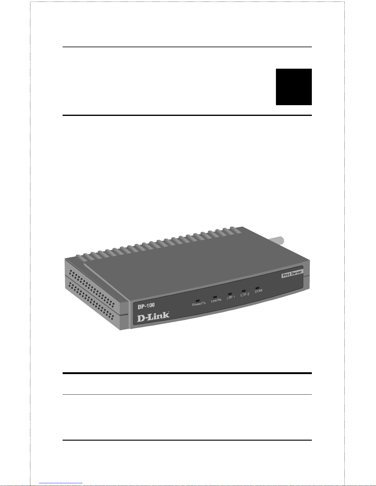
The DP-100 Print Server is a compact print server which connects to your
Ethernet network anywhere you wish to locate printer services. It manages
the flow of print files from your workstations or file servers to its connected
printers, delivering print jobs to high-performance printers much faster than
a file server or a PC acting as a print server can.
Figure 1 - 1 D P- 100 Print Server
DP-100 Print Server Features
DP-100 print servers improve network printing services in three ways:
Page 14

2
Introduction
♦
The DP-100 picks up the workload of managing print file traffic to
its connected printers. This provides workload relief to your file
servers, and allows the file servers' full capacity to be used for file
access or other direct services to network users. On peer-to-peer
networks, workstations can print directly to the DP-100 without
increasing the load of another workstation or server.
♦
The DP-100's parallel printer ports are IEEE 1284 compliant highspeed bidirectional ports, which can transmit to high-speed laser
printers much faster than a PC's parallel printer port. High-speed
laser printers connected to the DP-100's parallel ports can be
operated at full their capacity.
♦
Because the DP-100 is very portable and inexpensive compared to a
PC-based print server, and because the DP-100 connects to your fileservers through the network, printers can be deployed to locations of
maximum conve ni enc e to users.
The DP-100 offers extraordinary flexibility, operating with all major
network operating systems and protocols:
♦ IPX/SPX
Novell NetWare 3.x, 4.x (Using either bindery emulation or native NDS)
♦ TCP/IP
UNIX lpr/ l p d (HP- UX, SunOS, Solaris, SCO, Uni x W a r e , IBM AIX)
Windo ws NT
♦ NetBEUI
Windows NT, Windows 95, Windows for W orkgroups, Microsoft LAN
Manager, IBM LAN Server
♦ AppleTalk
MacOS EtherTalk
Page 15
DP-100 Multiprotocol Ethernet Print Server User’s Guide
Introduction
3
Windows-based setup and administration software,
PS Admin
, is supplied
with the DP-100, making configuration and management quick and easy.
The DP-100 also supports configuration and management via the
telnet
protocol for networks without Windows-compatible machines.
External Features
This section describes the externally visible features of the DP-100 print
server.
Port Connectors
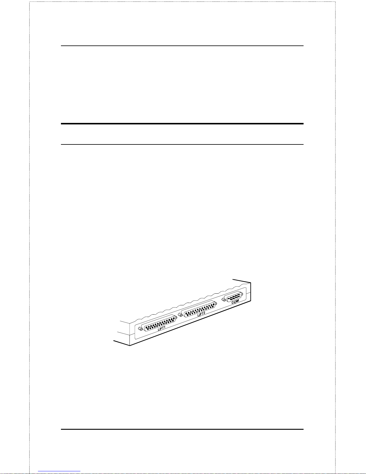
The DP-100’s three printer ports are located on its rear panel. Two identical
parallel ports are labeled LPT1 and LPT2; the single serial port is labeled
COM. These printer ports are independently configurable using the
PS
Admin
program or the print serve r’s
telnet
interface. (See the
Print Server
Administration User’s Guide
for information about configuring the print
server’s ports.)
Figure 1 - 2 Por t C onne c tor s
Page 16
4
Introduction
Network Cable Connectors
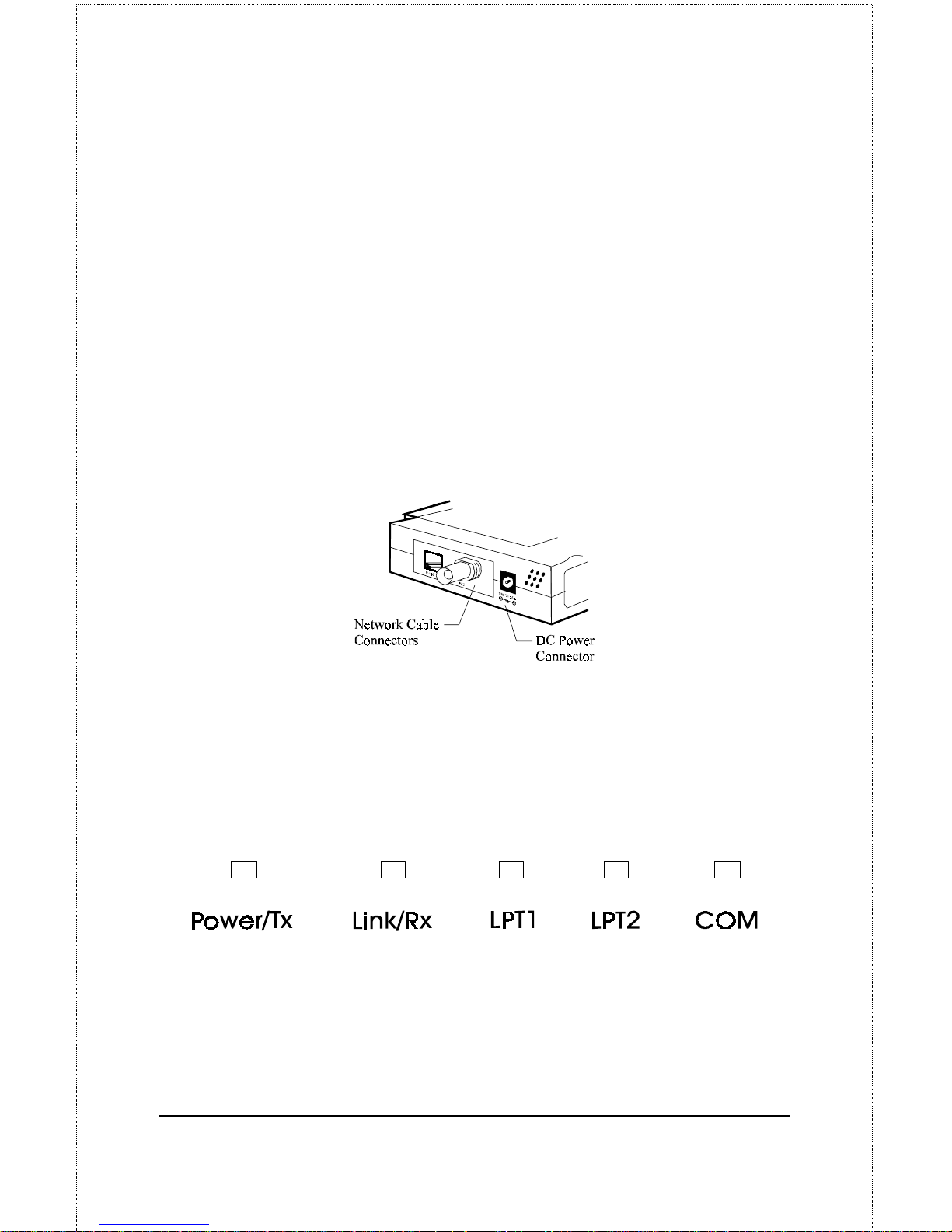
The DP-100 features two alternative network cable connectors for either
twisted-pair 10Base-T cabling (using an RJ-45 connector) or thin coaxial
10Base2 cabling (using a BNC connector). Both of these network cable
connectors are located on the DP-100’s right side panel.
DC Power Connector
The DC power input connector is located on the DP-100’s right side panel
and is labeled DC 12V.
Figure 1 - 3 Pr int Server Right Side P a ne l
LED Indicators
The front panel of the DP-100 features five LED indicators:
Figure 1 - 4 Fr ont P a ne l LED Indic a t or s
♦ Power/Tx
◊
Steady or flashing green c onfi rms tha t the DP-100 is powered on.
Page 17

DP-100 Multiprotocol Ethernet Print Server User’s Guide
Introduction
5
◊
The indicator blinks off briefly to indicate that the DP-100 is
transmitting to the network.
♦ Link/Rx
◊
Steady or flashing green confirms that the DP-100 has a good
connection to the Ethernet network.
◊
The indicator blinks off briefly to indicate that the DP-100 is
receiving from the network.
♦ LPT1, LPT2, COM
◊
These LED indicators light to show that the DP-100 is
transferring print data through the appropriate parallel or serial
port.
These three indicators are also used by the print server’s power-on
self t e st (POST) t o indicate any hardware failures.
Page 18

6
Unpacking and Installation
2
2 U
NPACKING AND
I
NSTALLATION
This chapter explains how to install your DP-100 print server and connect it
to the network. It also describes the print server self test indications, and
tells how to wall-mount your print server.
Unpacking and Inspecting the Print
Server
Carefully remove all items from the package. In addition to this
Hardware
User’s Guid e
, be certain that you have:
♦
One DP-100 print server
♦
One DC power adapter suitable for your country’s electric power
♦
Two
PS Admin
software diskettes
♦ One Pri n t S e rv er Admin i st ra t ion User’s Gu i d e
♦
Fasteners for optional wall-mounting
If any item is missing, or if you find any damage or mismatch, promptly
contact your dealer for assistance.
Page 19

DP-100 Multiprotocol Ethernet Print Server User’s Guide
Unpacking and Installation
7
Installing the DP-100
WARN IN G:
Configuration problems may result if the DP100 is powered up without first establishing its
network connection. Follow this procedure to
avoid compl i cati ons at the c onfigur ati on s tage.
1.
Confirm proper operation of each of the printers to be connected to
the DP-100. If you test your printers by printing test files directly
from a PC, then make each printer’s test connection to the PC
through the same port (serial or parallel) as the one you plan to use in
connecting to the DP-100.
2.
When you have confirmed proper operation of each printer, switch
its power off.
3.
Confirm that your network is operating normally.
4.
Connect the DP-100 to the network cable, using either the RJ-45
(10Base-T) or BNC (10Base2) connector on the print server’s side
panel.
5.
While each printer is powered off, connect its tested and confirmed
port with a like printer port of the DP-100. If you are connecting
fewer than three printers, then keep in mind that parallel- port
connections are preferred for high-performance printers.
6.
Switch on each connected printer.
7.
Plug the DC power adapter’s DC output plug into the DC 12V power
socket on the side pane l of the DP-100.
8.
Plug the power adapter into an electric service outlet. This will
supply power to the DP-100, as it has no external power switch. The
Page 20
8
Unpacking and Installation
Power/Tx LED on the DP-100’s front panel should light steady
green, and the DP-100’s self-test will proceed.
Power On Self-Test
When the DP-100 is powered on, it automatically performs a self-test on
each of its major components. The final result of the self-test is signaled by
the state of the LPT1, LPT2, and COM LED indicators following the selftest. Preliminary to the actual component tests, the three LED indicators
are tested to confirm their steady and flashing operation.
Immediately after power-up, all five of the LED’s should show steady green
for several seconds. The n the L PT1, LPT2, a nd COM LEDs should flash on
simultaneously three times. Irregularity of any of the three LEDs during
these LED tests may mean there is a problem with the LEDs themselves.
Contact your dealer for correction of any LED problems before proceeding.
The actual component tests immediately follow the LED tests. A normal
(no fault) result is signaled by a series of three cycles of sequential flashing
of the three LEDs, followed by a quiescent state with all three LEDs dark.
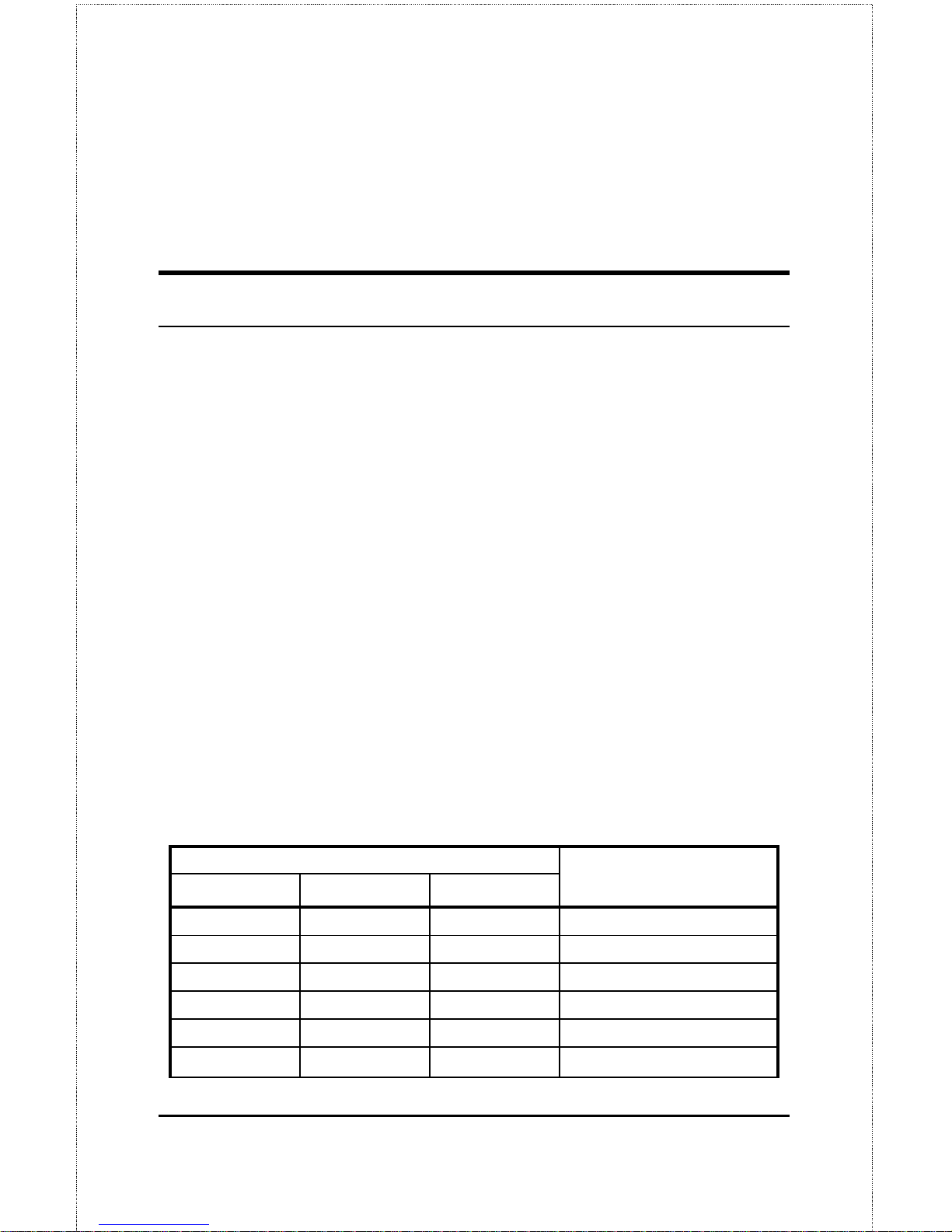
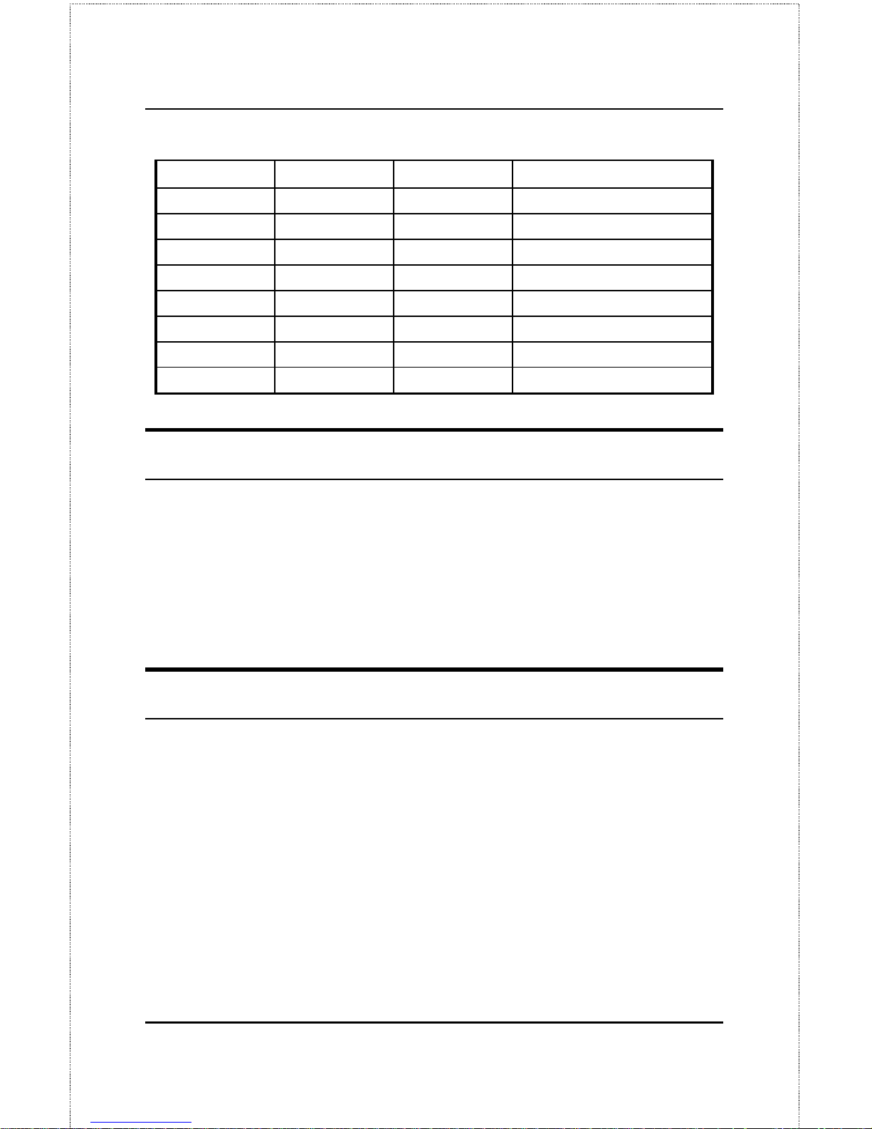
If the self-test routi ne traps any component error, then following the LED
tests the self-test will halt and the LED’s will continuously signal the error
according to the following table. In the event of any such error signal,
contact your dealer for correction of the faulty unit.
LED Name Faulty
LPT1 LPT2 COM
Component
off off on/steady COM error
off off flashing Flash ID error
off on/steady off LPT2 error
off on/steady on/stead y LAN Con t roller error
off on/steady flashing LAN Memory error
off flashing off
Paralle l-2 Controller error
Page 21
DP-100 Multiprotocol Ethernet Print Server User’s Guide
Unpacking and Installation
9
off flashing on/steady
EEPROM error
off flashing flashing Flash Protected
on/steady off off LPT1 error
on/steady off on/steady Timer INT error
on/steady off flashing LAN IO Base error
on/steady on/steady off RAM error
flashing off off Paralle l-1 Controller error
flashing flashing off Flash erase/program error
flashing flashing flashing Need to reload firmware
Testing Your DP-100
The
PS Admin
software includes a Print Test function for confirmation of
printer cable connections and functions. That operational test can be
completed after you have installed the
PS Admin
software, and have
configured your DP-100 and its ports. See the
Testing Your Print Server
section of the
Print S e rv er Admin i st ra t ion User’s Gu i d e
.
Wall-Mounting the DP-100
The bottom of the DP-100’s case has a pair of wall-mount sockets, and
screws and nylon anchors are supplied, to facilitate mounting the DP-100 to
a wall or partition adjacent to your printers.
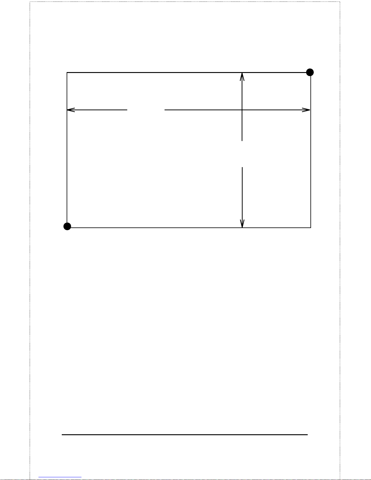
To mount the DP-100 with the front panel facing up (and the printer port
connectors facing down), set the two mounting screws at the lower-left and
upper-right corners of a rectangle as shown below (actual size):
Page 22
10
Unpacking and Installation
443 PP
7
8
249LQ
:3 PP
5
6
27LQ
When setting the screws into the wall or partition, leave about 3 mm (
1
/8 in)
between the head of each screw and the wall surface. Then place the DP100 so that the mounti ng sockets on the bottom of its case fit over the two
screws. Press the case gently toward the wall and slide the case at a 45
°
angle downward and leftward to engage the screwheads in the slots of the
mounting sockets.
Page 23

DP-100 Multiprotocol Ethernet Print Server User’s Guide
Product Specifica tions
11
A
3 P
RODUCT
S
PECIFICATIONS
Printer Connection
Standards
: IEEE 1284 bi-directional parallel interface, RS-232
Ports:
Bi-directional 25-pin parallel ports × 2, 9-pin DTE serial port × 1
Parallel Port Bi-directional Communication:
Hewlett-Packard PJL
(Printer Job Language) supported
Network Connection
Network St a ndards
: IEEE 802.3 10BASE2/10BASE-T Ethernet
Network Data Transfer Rate
: 10Mbps
Network Connectors
: BNC connector for 10BASE2 shielded pair
connection, RJ-45 connector for 10BASE-T unshielded twisted pair
connection (auto-switching)
Page 24

12
Product Specifica tions
Network Protocols
Ethernet Frame Types:
802.2, 802.3, E t he rnet II, SNAP (a ut o-switching)
Transport Protoc ol s:
IPX/SPX, T C P/ I P, NetBE UI , AppleTalk/EtherTalk
TCP/IP Pr otoc ol s Suppor te d:
BOOTP, SNMP, Telnet, TFTP, FTP, lpd
Management and Diagnostics
Standard:
SNMP
MIBs
: MIB-II (RFC 1213)
Diagnostic LED Indicators
: Power/Tx, Link/Rx, LPT1, LPT2, COM
Environmental and Physical
Power Suppl y
: External power supply provi di ng 12VDC/ 500mA
Dimensions
: 190mm × 116.8mm × 30.9mm
Weight
: approx. 360g
Operating Temperature
: 0 to 55°C
Storage Temperature
: -20 to 55°C
Humidity
: 5% to 90% non-condensing
Emissions
: FCC Class A, CISPR 22 Class A, VCCI Class 1, AS/NZS
3548:1995 Class A
Page 25

DP-100 Multiprotocol Ethernet Print Server User’s Guide
Product Specifica tions
13
Safety
: UL (UL 1950), CSA (CSA950), TUV/GS (EN60950)
Page 26
14
Port Pinouts
B
4 P
ORT
P
INOUTS
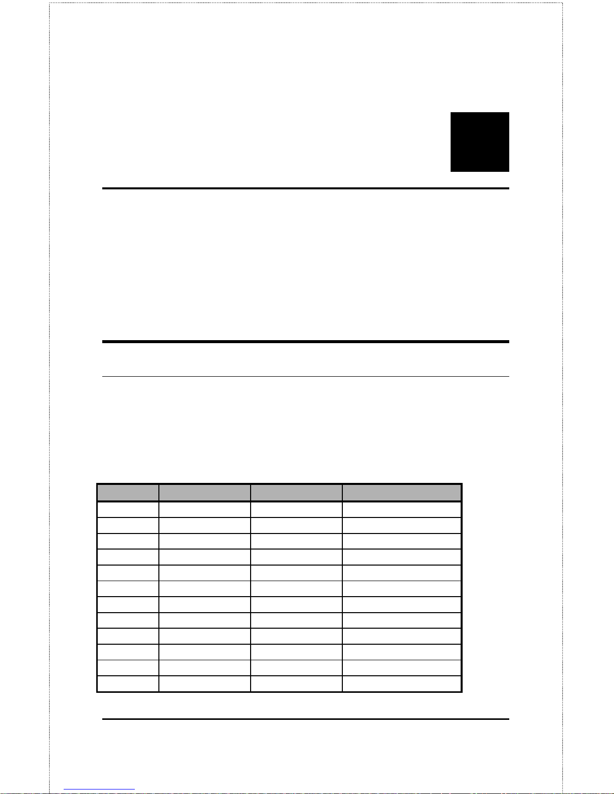
This appendix shows the pinouts of the DP-100 parallel and serial printer
ports.
Parallel Ports
The following table lists the pinouts of the print server’s 25-pin parallel port
connector (identical to the connector used on most personal computers), as
well as the 36-pin Centronics connector used on most printers.
Signal names beginning with n are active-low signals.
25-pin Centronics Signal Source
1 1 nStrobe Host
2 2 Data 1 Bi-directional
3 3 Data 2 Bi-directional
4 4 Data 3 Bi-directional
5 5 Data 4 Bi-directional
6 6 Data 5 Bi-directional
7 7 Data 6 Bi-directional
8 8 Data 7 Bi-directional
9 9 Data 8 Bi-directional
10 10 nAck Print er
11 11 Busy Print er
12 12 PError Printer
Page 27
DP-100 Multiprotocol Ethernet Print Server User’s Guide
Index
15
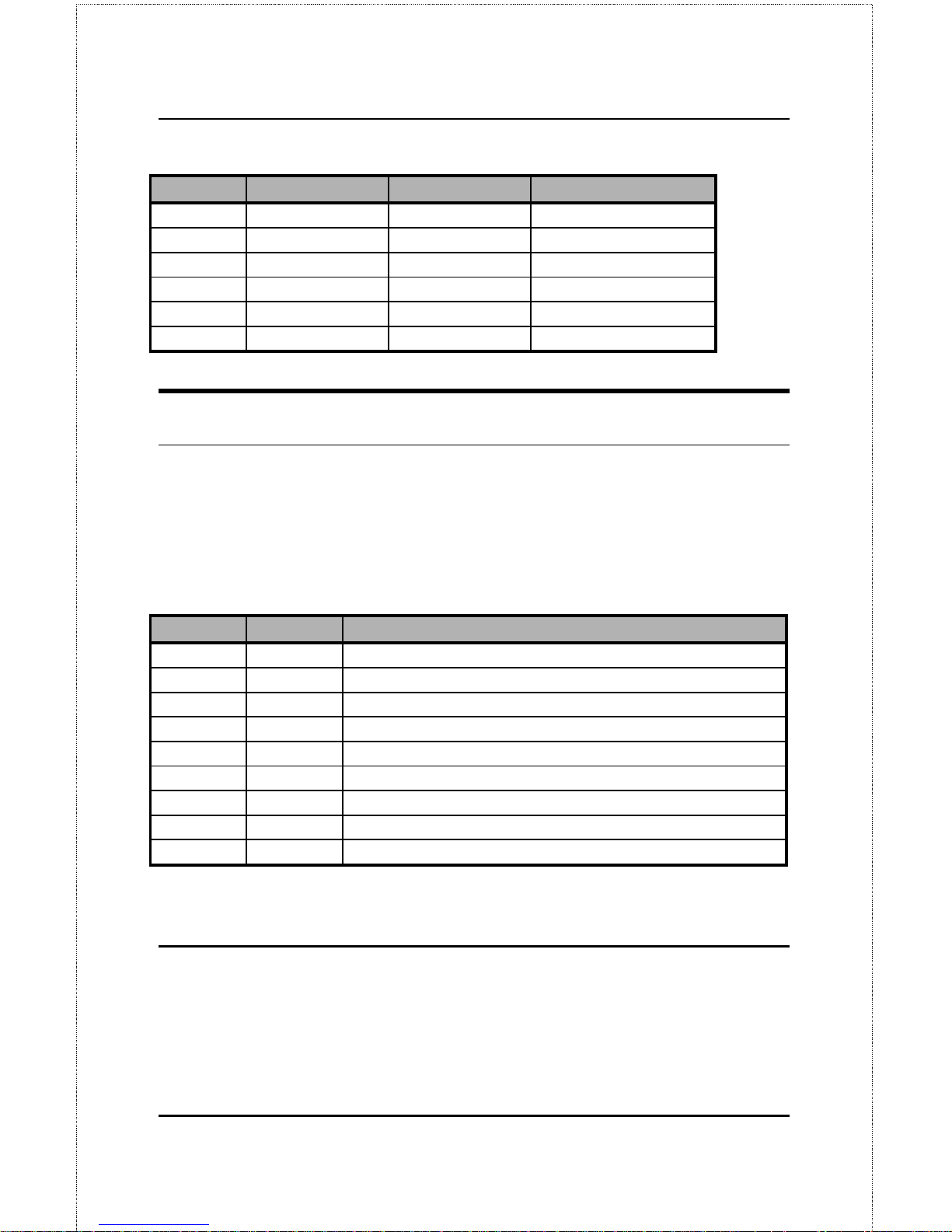
25-pin Centronics Signal Source
13 13 Select Printer
14 14 nAutoFd Host
15 32 nFault Printer
16 31 nInit Host
17 36 nSelectIn Host
18-25 16, 17, 19-30 Ground
Serial Port
The table be low shows the pinout of the pri nt server’s 9-pin RS-232 serial
port. The print server’s serial port is a DTE (Data Terminal Equipment)
port, and should be connected to a DCE (Data Communications Equipment)
serial port on your printer. Consult your printer’s documentation for
detailed information on how to connect the print server to your printer.
9-pin Signal Function
1 DCD Data Carri er Detected (DCEÆDTE)
2 RXD Received Data ( DCEÆDTE)
3 TXD Transmitted Dat a ( DTEÆDCE)
4 DTR Data Terminal Ready (DTEÆDCE)
5 Gnd Signal Ground
6 DSR Data Set Ready ( DCEÆDTE)
7 RTS Request to Send (DTEÆDCE)
8 CTS Clear to S end ( DCEÆDTE)
9 RI Ring Indi c ator (DCEÆDTE)
5 I
NDEX
Page 28

16
Index
10Base2....................................................4, 7
10Base-T..................................................4 , 7
COM.............................................................3
COM LED................................................5, 9
DC power adapter.....................................6, 8
IEEE 1284....................................................2
Link/Rx LED................................................5
LPT1.............................................................3
LPT1 LED ................................................5 , 9
LPT2.............................................................3
LPT2 LED ................................................5 , 9
network connectors ......................................4
packing list .................................................. 6
pinout
parallel port.............................................14
serial port................................................15
Power/Tx LED......................................... 5, 8
Print Test function....................................... 9
printer port connectors................................. 3
PS Admin
software...............................3, 6, 9
self-test........................................................8
telnet............................................................ 3
wall mounting ............................................ 10
wall-mounting..............................................6
Page 29

Offices
U.S.A. D-LINK SYSTEMS, INC.
5 Musick Irvine, CA 92618 USA
TEL: 1-714-455-1688 FAX : 1-714-455-2521
CANADA D-LINK CANADA, INC.
2180 Dunwin D rive, Unit # 6,
Missi ssauga Ontario, L5L 5M8, Canada
TEL: 1-905-828-0260 FAX : 1-905-828-5669
U.K. D-LINK (EUROPE) LTD.
D-Link House, 6 Garland Road, Stanmore, London HA7 1DP U.K.
TEL: 44-181-2355555 FAX: 44- 181-2355500
GERMANY D-LINK (DEUTSCHLAND) GMBH I.G.
Bachstrae 22, 65830 Kri ftel Germa ny
TEL: 49-6192-97110 FAX: 49- 6192-971111
FRANCE D-LINK FRANCE
Le FLORILEGE #2, Allee de la Fresnerie
78330 Fontena y L e Fleury France
TEL: 33-1-30238688 FAX: 33-1- 30238689
SWEDEN D-LINK A / B
World Trade Ce nt er P. O . Box 70396, 107 24 Stockholm Sweden
TEL: 46-8-7006211 FAX: 46-8- 219640
DENMARK D-LINK DENMARK
Nave rland 2 DK -2600 Glostrup Copenhagen, De nmark
TEL:45-43-969040 FAX:45-43-424347
SINGAPORE D-LINK SINGAPORE PTE.LTD.
77 Scie nce Par k Drive #03- 03 CINTECH III,
Singapore Science Park Singapore 118256
EL : 65-7746233 FA X: 65-7746322
AUSTRALIA D-LINK AUSTRALIA PTY.LTD.
Unit 16, 390 Easte rn Valley Way Roseville, NSW 2069 Austra l i a
TEL: 61-2-94177100 FAX: 61-2- 94171077
CHINA D-LINK BEIJING
15th Floor, S cience & Te chnology Towe r
No. 11, Baishiqi ao Road, Haidia n District, Beijing 100081 China
TEL: 86-10-68467106-9 FAX: 86-10- 68467110
JAPAN D-LINK TOKYO
5F, 3-9-1 T ogoshi, Shinagawa-ku Tokyo 142 Japan
TEL: 81-3-5751-2351 FAX: 81- 3-5751-2352
INDIA D-LINK (INDIA) PVT. LTD.
Bombay Office : Plot No.5, Kurla-Bandra Complex Rd.
Off C st Rd., S antacruz (E) Bombay - 400 098 India
TEL: 91-22-6172478 FAX: 91-22-6172476
TAIWAN D-LINK TAIWAN
2F, No. 233-2 Pao-Chi ao Rd, Hsin-Tie n, Taipei,Tai wan, R .O.C.
TEL: 886-2-916-1600 FAX: 886-2-914-6299
Page 30

Page 31
Registration Card
Print, type or use bl ock letters.
Your name: Mr./Ms_____________________________________________________________________________
Organization: ________________________________________________Dept. ____________________________
Your title at organization:________________________________________________________________________
Telephone:_______________________________________ Fax:________________________________________
Organization's full address: ______________________________________________________________________
____________________________________________________________________________________________
Country: _____________________________________________________________________________________
Date of purchase (Month/Day/Year): _______________________________________________________________
3URGXFW 0RGHO 3URGXFW 6HULDO
1R1
- 3URGXFW LQVWDOOHG LQ W\SH RI
FRPSXWHU +H1J1/ &RPSDT 7;9,
- 3URGXFW LQVWDOOHG LQ
FRPSXWHU VHULDO 1R1
(* Applies to adapters only)
Product was purchased from:
Reseller's name: ______________________________________________________________________________
Telephone:_______________________________________ Fax:________________________________________
Reseller's full address: _________________________________________________________________________
_________________________________________________________________________
_________________________________________________________________________
Answers to the fol lowing questions help us to support your product:
1. Where and how will the product primarily be used?
†Home †Office †Travel †Company Business †Home Business †Personal Use
2. How many employees work at installation site?
†1 employee †2-9 †10-49 †50-99 †100-499 †500-999 †1000 or more
3. What network protocol(s) does your organization use ?
†XNS/IPX †TCP/IP †DECnet †Others_____________________________
4. What network operating system(s) does your organization use ?
†D-Link LANsmart †Novell NetWare †NetWare Lite †SCO Unix/Xenix †PC NFS †3Com 3+Open
†Banyan Vines †DECnet Pathwork †Windows NT †Windows NTAS †Window s '95
†Others__________________________________________
5. What network management program does your orga nization use ?
†D-View †HP OpenView/Windows †HP OpenView/Unix †SunNet Manager †Novell NMS
†NetView 6000 †Others________________________________________
6. What network medi um/media does your organization use ?
†Fiber-optics †Thick coax Ethernet †Thin coax Ethernet †10BASE-T UTP/STP
†100BASE-TX †100BASE-T4 †100VGAnyLAN †Others_________________
7. What applications are used on your network?
†Desktop publishing †Spreadsheet †Word processing †CAD/CAM
†Database management †Accounting †Others_____________________
8. What category best describes your company?
†Aerospace †Engineering †Education †Finance †Hospital †Legal †Insurance/Real Estate †Manufacturing
†Retail/Chainstore/Wholesale †Government †Transportation/Utilities/Communication †VAR
†System house/company †Other________________________________
9. Would you recommend your D-Link product to a friend?
†Yes †No †Don't know yet
10.Your comments on this product?
__________________________________________________________________________________________
__________________________________________________________________________________________
Page 32
 Loading...