

Page 1
1
Page 2

ShareCenter Pro DNS-1550-04 User Manual
2
Contents
Chapter 1: Introduction ................................................................................ 5
1.1 About This Manual ........................................................................ 5
1.2 Protocol Support ........................................................................... 6
1.3 Hardware Specific ations ............................................................... 6
1.4 Client Utility OS Support ............................................................... 7
1.5 Browser Support ........................................................................... 7
Chapter 2: Quick Setting-up ........................................................................ 9
2.1 Unpacking the ShareCenter® Pro DNS-1550-04 .......................... 9
2.2 Installing Disk Drives................................................................... 10
2.3 Connecting the Ethernet cable ................................................... 13
2.4 Connecting the Power ................................................................ 13
2.5 Shutting Down the ShareCenter Pro DNS-1550-04 ................... 13
2.6 Setup Wizard .............................................................................. 15
2.7 Replacement of Power Supply Units (PSU) ............................... 18
2.8 Replacement of Control Module ................................................. 19
Chapter 3: WebPAM PROe ......................................................................... 20
3.1 Quick Start .................................................................................. 20
3.2 Dashboard T ab ............................................................................ 22
3.2.1 System Status ................................................................ 22
3.2.2 Event Information ........................................................... 23
3.2.3 Storage Overview........................................................... 23
3.3 Device T ab .................................................................................. 25
3.3.1 Front View ...................................................................... 25
3.3.2 Back View ...................................................................... 26
3.3.3 Component List .............................................................. 27
3.3.4 Physical Dr i ve ................................................................ 30
3.3.5 iSCSI .............................................................................. 31
3.3.6 Network .......................................................................... 33
3.3.7 UPS ................................................................................ 36
3.3.8 External Drive ................................................................. 36
3.4 Storage T ab ................................................................................. 38
Page 3

3
3.4.1 Create Disk Array ........................................................... 39
3.4.2 Disk Array Management ................................................. 43
3.4.3 Logical Drive Management ............................................ 44
3.4.4 Spare Drive Management .............................................. 47
3.5 AdminT ool Tab ............................................................................ 49
3.5.1 System settings and clearing statistics .......................... 49
3.5.2 Services ......................................................................... 51
3.5.3 Runtime and NVRAM event logs ................................... 51
3.5.4 Background activity, settings and schedules ................. 54
3.5.5 Firmware updates .......................................................... 60
3.5.6 Performance monitor ..................................................... 61
3.5.7 Restore factory default settings ..................................... 63
3.5.8 Import/Export a system configuration file ....................... 64
3.5.9 LUNMap Management ................................................... 65
3.5.10 Power Option ................................................................. 66
3.5.11 Message Alert ................................................................ 66
3.5.12 Network Security ............................................................ 67
3.6 NAS Tab ...................................................................................... 70
3.6.1 Setup Wizard .................................................................. 70
3.6.2 User account management ............................................ 72
3.6.3 Protocol Control and Setting .......................................... 74
3.6.4 File System Management .............................................. 74
3.6.5 File Sharing Setting ........................................................ 75
3.6.6 Backup ........................................................................... 78
3.6.7 Plug-in Management ...................................................... 85
3.6.8 iSCSI Initiator ................................................................. 86
Chapter 4: ShareCenter® NAVI................................................................... 87
4.1 Working with ShareCenter® NAVI ............................................... 87
4.1.1 Opening the Main Window ............................................. 87
4.1.2 Choosing a ShareCenter® NAVI Language ................... 89
4.1.3 Starting the Advanced Storage Manager ....................... 90
4.1.4 Viewing ShareCenter® NAVI Information ....................... 91
4.1.5 Closing ShareCenter® NAVI ........................................... 93
4.2 Managing Backups ..................................................................... 95
4.2.1 Doing a Backup Now ..................................................... 95
4.2.2 Scheduling a Backup ................................................... 100
4.2.3 Viewing Backup Schedules .......................................... 105
4.2.4 Changing a Scheduled Bac kup .................................... 105
4.2.5 Deleting a Scheduled Backup ...................................... 108
Page 4

ShareCenter Pro DNS-1550-04 User Manual
4
4.2.6 Restoring Backed-up Files ........................................... 109
4.2.7 Viewing the Backup Event Log .................................... 112
4.2.8 Saving the Event Log ................................................... 113
4.2.9 Clearing the Event Log ................................................ 115
4.2.10 Setting the Port ............................................................ 116
4.3 Managing Share Folders .......................................................... 117
4.3.1 Opening a Share Folder ............................................... 117
4.3.2 Viewing a List of Share Folders ................................... 118
4.3.3 Mounting a Share Folder /Creating a Network Drive ... 120
4.3.4 Un-mounting a Share Folder /Disconnecting a Network
Drive ............................................................................. 121
4.3.5 Setting up a Share Folder for Time Machine ............... 122
4.4 Making Management Settings .................................................. 124
4.4.1 Configuring a NAS System .......................................... 124
4.4.2 Locating the ShareCenter® Pro DNS-1550-04 ............ 129
4.4.3 Wake-on-LAN ............................................................... 130
4.4.4 Choosing a Default NAS System ................................. 130
4.4.5 Viewing the System Event Log .................................... 131
4.4.6 Viewing a List of Plug-ins ............................................. 134
4.4.7 Viewing Plug-in Versi on Numbers ................................ 134
4.4.8 Enabling and Disabling Plug-ins .................................. 135
4.4.9 Removing Plug-ins ....................................................... 138
4.4.10 Rebooting the ShareCenter® Pro DNS-1550-04 .......... 139
4.4.11 Shutting Down the ShareCenter® Pro DNS-1550-04 ... 141
Chapter 5: Troubleshooting ..................................................................... 143
5.1 WebPAM PROe system event log ............................................ 143
5.2 How to use USB Retrieval to export system information .......... 154
Chapter 6: Warranty .................................................................................. 155
Chapter 7: Tech Support .......................................................................... 162
Chapter 8: Registration ............................................................................ 163
Page 5

5
Chapter 1: Introduction
1.1 About This Manual
This Product Manual describes how to setup, use, and maintain the
ShareCenter
®
Pro DNS-1550-04. It also describes how to use:
• ShareCenter
®
NAVI software that you insta ll and run on your
Windows or Mac
• Advanced Storage Manager WEBPAM PROe software that runs
on the ShareCenter
®
Pro DNS-1550-04 by browser.
This manual includes a full table of contents, chapter task lists, and
numerous cross-references to help you find the specific information you
are looking for.
Also included are four levels of notices:
Note
A Note Provides helpful information such as hints or alternative ways of
doing a task.
Important
An Important calls attention to an essential step or point required to
complete a task. Important items include things often missed.
Caution
A Caution informs you of possible equipment damage or loss of data and
how to avoid them.
Warning
A Warning notifies you of Probable equipment damage or loss of data, or
the possibility of physical injury, and how to avoid them.
Page 6

ShareCenter Pro User Manual
6
1.2 Protocol Support
ShareCenter® Pro DNS-1550-04 series supports:
• SMB/CIFS for Microsoft Windows
• NFS for Linux/Unix
• AFP for Mac
• FTP
• WebDAV for the file transform over the Internet
• iSCSI Target model and Initiator model
1.3 Hardware Specificati o ns
Model Name
DNS-1550-04(Dual PSU)
CPU
1.8 GHz
FLASH
256 MB
SDRAM
2GB DDRII
Smart Fan
Yes
Gigabit Ethernet
2
USB 2.0 Host port
5 (Front x 1/ Back x 4)
Internal HDD Support
3.5" 3 Gb/s SATAII
Hot Plug
Yes
# of Bays
4
Power Supply
226W*2 (80 PLUS)
Dimension
429(L) x 442(W) x 44(H) mm
( 16.9 x 17.4 x 1.7 inches)
Page 7

7
1.4 Client Utility OS Support
The following operating systems support ShareCenter® NAVI:
• Windows
®
XP 32/64 Bit
• Windows Vista
®
32/64 Bit
• Windows
®
Server 2003 32/64 Bit
• Windows
®
Server 2008 32/64 Bit
• Windows
®
Server 2008 R2
• Windows
®
7 32/64 Bit
• Mac OS 10.5 and above
• Mac OS 10.6 XServer
1.5 Browser Support
Choose one of the following browsers to use with WEBPAM PROe:
• Internet Explorer 7 and above
• Firefox 3 and above
• Safari 5 and above
• Google Chrome 8 and above
Warning
The electronic components within the ShareCenter
®
Pro
DNS-1550-04 are sensitive to damage from Electro-Static
Discharge (ESD). Observe appropriate precautions at all
times when handling the ShareCenter
®
Pro DNS-1550-04
or its subassemblies.
Page 8
ShareCenter Pro User Manual
8
Important
To configure the ShareCenter
®
Pro DNS-1550-04, you
are advised to install ShareCenter
®
NAVI. Please refer
to the User Manual.
Warning
The fan contains hazardous moving parts. Keep fingers
away.
Caution
RISK OF EXPLOSION IF BATTERY IS REPLACED BY
AN INCORRECT TYPE.
CE:
WARNING
This is a class A Product. In a domestic environment this Product may case
radio interference in which case the user may be required to take adequate
measures.
VCCI
BSMI
警告使用者
:
這是甲類的資訊產品,在居住的環境中使用時,可能會造成射頻干擾,在這種
情況下,使用者會被要求採取某些適當的對策。
Page 9
9
Chapter 2: Qu ick Setting-up
2.1 Unpacking the ShareCenter® Pro DNS-1550-04
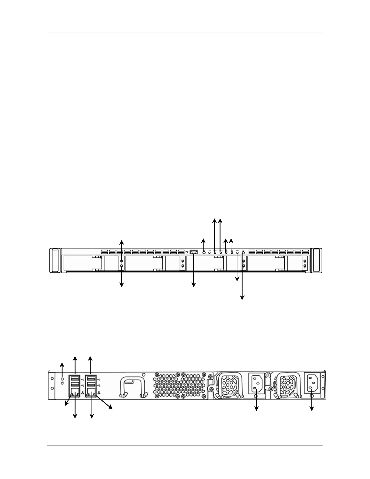
The ShareCenter® Pro DNS-1550-04 series box contains the following
items:
• ShareCenter
®
Pro DNS-1550-04 Unit
• Quick Installation Guide
• Screws for disk drives
• Ethernet cable
• Power cord
• CD for client utility and reference document
Figure 1. ShareCenter
®
Pro DNS-1550-04 Front View
Figure 2. ShareCenter
®
Pro DNS-1550-04 Rear View
USB
Connection
Drive
Status
LED
One-Touch
Backup Button
Drive
Activity
LED
Ethernet Port
Activity LEDs
PSU Status LEDs
System
Status
LED
Power
Button
RJ45 Ethernet
Network
Connections
Ethernet Port
Status LEDs
Reset
Button
Power Connections
USB
Connections
Ethernet
Port Status
LEDs
Page 10
ShareCenter Pro User Manual
10
2.2 Installing Disk Drives
Note: It is highly recommended to select enterprise Level HDD to
achieve the best data Prot e c tion.
You can populate the ShareCenter
®
Pro DNS-1550-04 series NAS with
SATA 1.5 Gb/s or 3.0 Gb/s disk drives. For optimal performance, install
disk drives of the same model and capacity. Your disk drives will become
a RAID Volume on the ShareCenter
®
Pro DNS-1550-04.
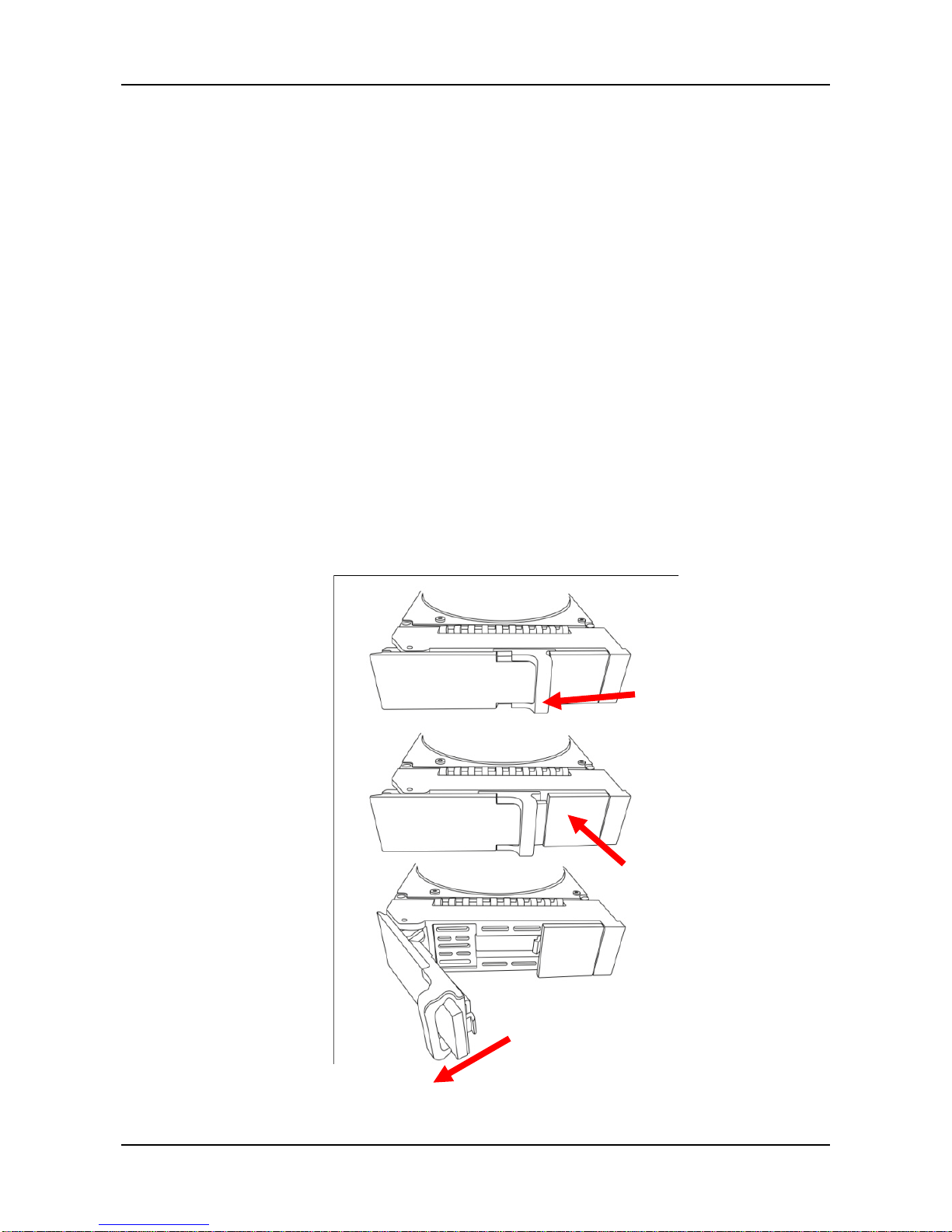
To install disk drives:
1. Remove the disk tray from the device by the following steps:
a. Slide the latch leftwards.
b. Press the button next to the latch.
c. Pull the latch out to open the door of disk tray, then you can
pull the disk tray out from the enclosure.
Page 11
11
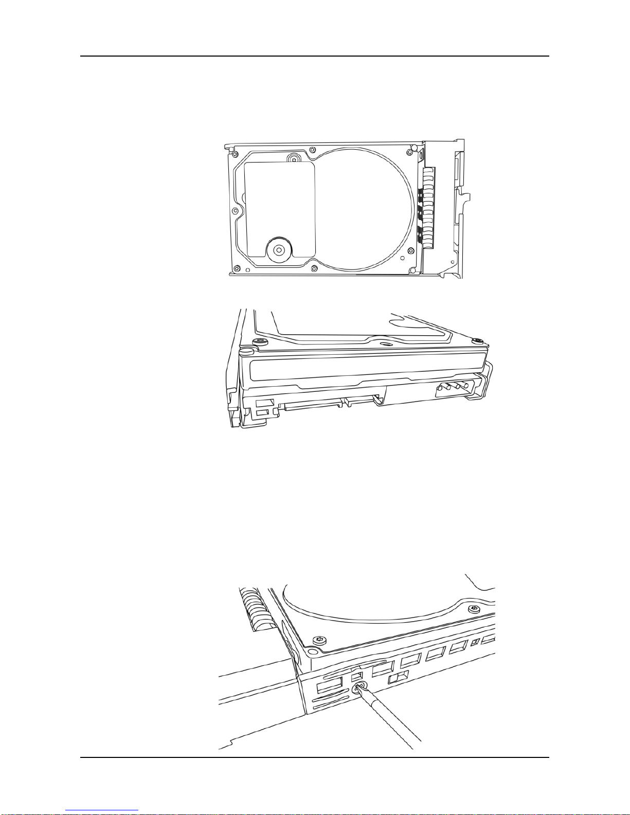
2. Carefully lay the disk drive into the drive tray, so that the screw
holes on the sides of the carrier align with the screw holes in the
drive.
3. Insert the screws through the holes in the drive carrier and into the
sides of the disk drive.
․ Only install the countersunk screws supplied with the
ShareCenter
®
Pro DNS-1550-04.
․ Install four screws per drive.
․ Snug each screw. Be careful not to over-tighten.
Page 12

ShareCenter Pro User Manual
12
4. Reinstall the drive tray into the ShareCenter
®
Pro DNS-1550-04
enclosure.
Tip: Repeat steps 1 through 4 until all of your disk drives are
installed.
Page 13

13
2.3 Connecting the Ethernet cable
To connect the ShareCenter® Pro DNS-1550-04 to your network:
1. Attach one end of the network cable to the RJ45 network
connection. See Figure 2.
2. Attach the other end of the network cable to your Ethernet hub or
switch.
2.4 Connecting the Power
To power the ShareCenter® Pro DNS-1550-04:
1. Attach the two power cords to the dual power supplies of the
ShareCenter
®
Pro DNS-1550-04 enclosure and plug the other
ends into the power source. See Figure 2.
2. On the front of the ShareCenter
®
Pro DNS-1550-04, press the
power button. See Figure 1. It takes about a minute to boot the
ShareCenter
®
Pro DNS-1550-04. When fully booted:
․ The System Status LED turns blue. See Figure 1.
․ The buzzer beeps one time.
2.5 Shutting Down the ShareCenter Pro DNS-1550-04
To shut down the ShareCenter® Pro DNS-1550-04, press and hold the
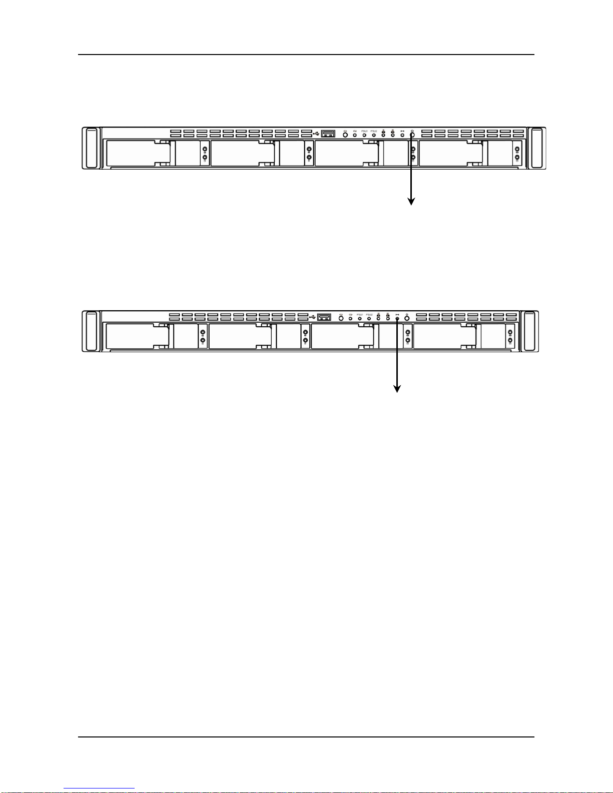
power button until the power LED indicator turns red. See Figures 3 and
4.
Page 14
ShareCenter Pro User Manual
14
Figure 3. Press and hold the Power button about 5 seconds
Figure 4. System status LED turns red, and then goes dark
To restart the ShareCenter
®
Pro DNS-1550-04, press the power button
again.
Power
Button
System
Status
Page 15
15
2.6 Setup Wizard
You can quickly set up your DNS-1550-04 system through the
WebPAMS PROe Wizard using either the One-Click Setup or using
Advanced-Setup.
1. Quick Setup by Setup Wizar d in WebPAM PROe
The system’s Wizard in W ebPAM PR O e lets you configure your
disk array(s) easily and quickly. The Wizard will guide you
through the required settings step by step. You can choose to
configure automatic al l y by using One-Click Setup, or configure
manually by using Advance Setup.
2. How to use Automatic Configuration Wizard?
․ Connect to the WebPAM PROe through your browser.
(Following steps below to log in Web-based configuration
manager )
․ 2.1. Start your browser (IE7 or above, FireFox 3 or above,
Google Chrome).
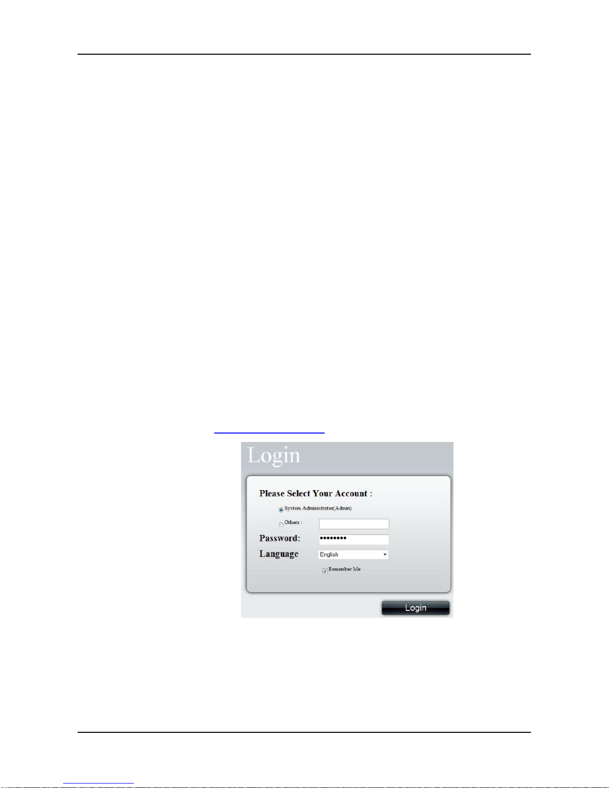
․ 2.2. On the URL address bar, type in the default IP
address
http://192.168.0.32
, The login screen will appear:
․
․ 2.3. Select “Admin” and type default password “password”
․ 2.4. Choose preferred language by clicking the Language
menu.
Page 16
ShareCenter Pro User Manual
16
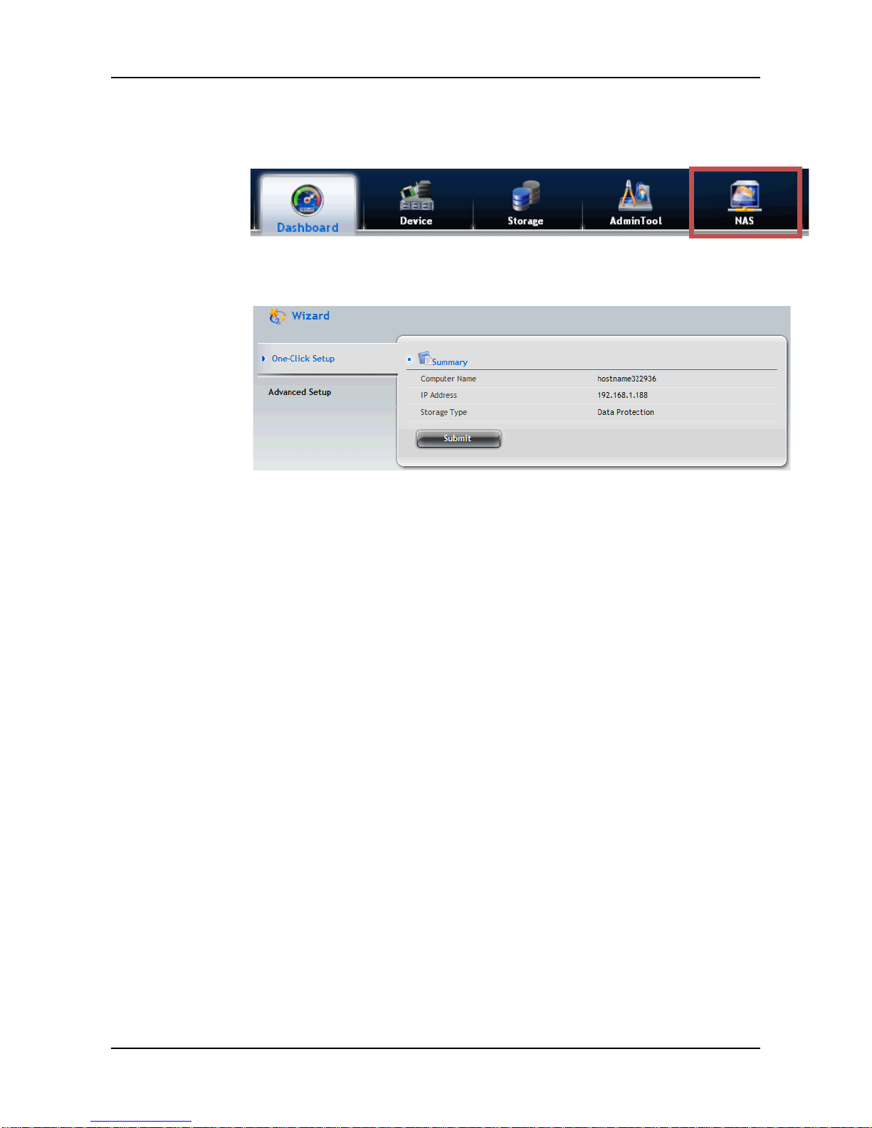
․ Click NAS tab > Wizard.
․
․ Click the One-Click Setup button. The Automatic
Configuration box displays:
․ The Summary window displays the general information of the
system, including:
․ Computer Name
․ IP Address
․ Storage Type
․ To accept the proposed configuration, click the Submit
button.
If you disagree with the proposed configuration, click the Advanced
Setup button to directly specify all parameters for a new disk array ,
logical drives, and spare drives.
Using Advanced Configuration Wizard
1. Click NAS tab > Wizard.
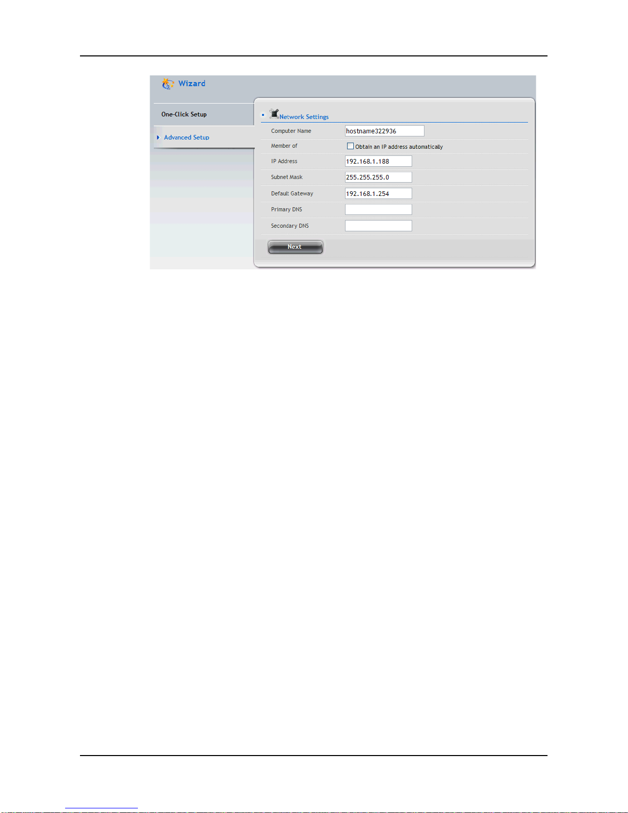
2. Click the Advanced Setup button. The Advanced Configuration
box displays:
Page 17
17
3. Complete the required settings in the Network Settings window,
including:
․ Computer Name
․ Obtain an IP address automatically
․ IP Address
․ Subnet Mask
․ Default Gateway
․ Primary DNS
․ Secondary DNS
When done, click the Next button.
Page 18
ShareCenter Pro User Manual
18
4. Select Storage Type: Data Protection or Maximum Capacity, and
then click the Next button.
5. The Summary window displays the general information of the
system, including:
․ Computer Name
․ IP Address
․ Storage Type
To accept the proposed configuration, click the Submit button.
2.7 Replacement of Power Suppl y Units (PSU)
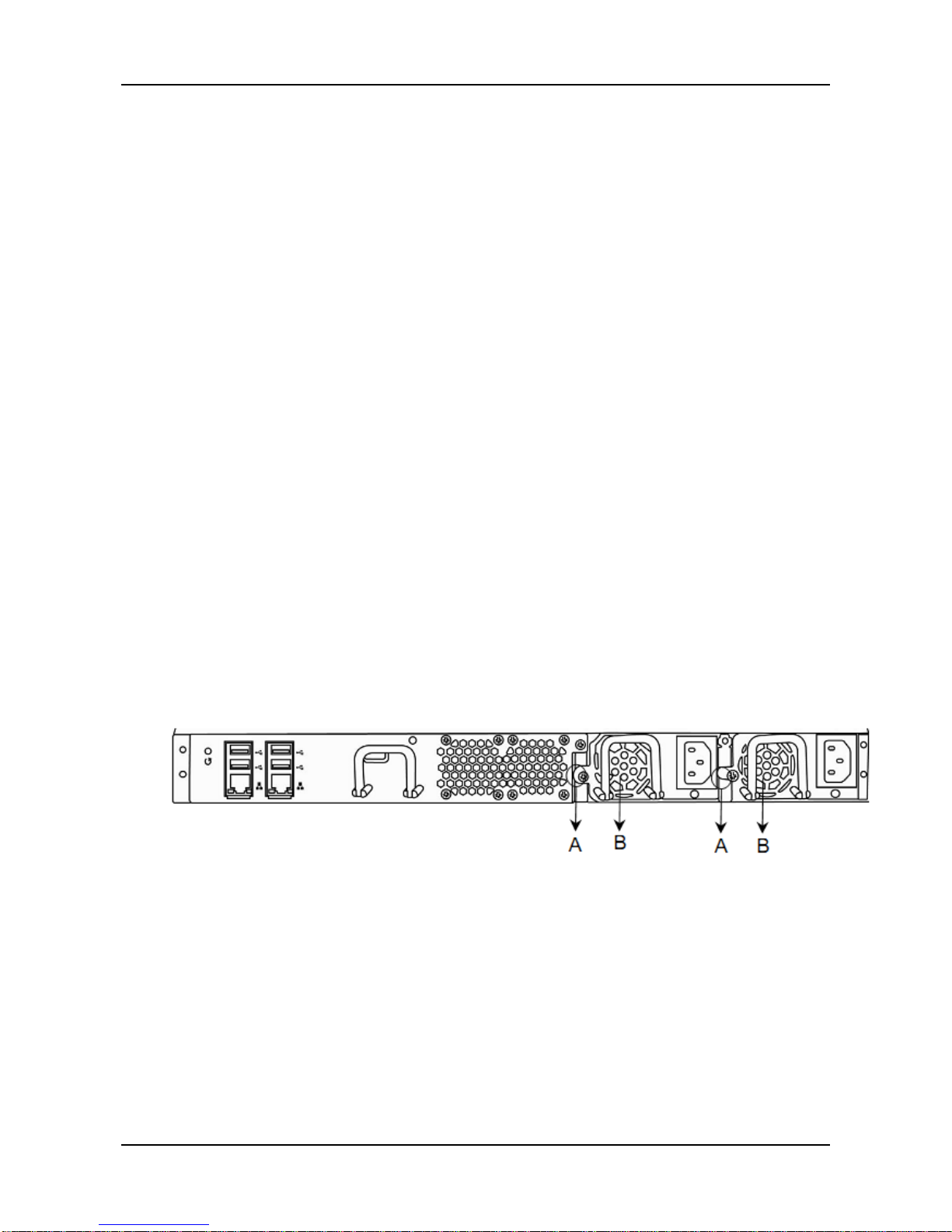
The DNS-1550-04 supports two hot-swappable PSUs. You may swap
either of the PSUs one at a time if an uninterruptable power supply is in
use.
Step 1. Loosen screw (A) on PSU to be replaced.
Step 2. Remove the PSU by pulling on the handle.
Step 3. Insert the new PSU.
Step 4. Tighten screw (A).
Page 19
19
2.8 Replacement of Control Module
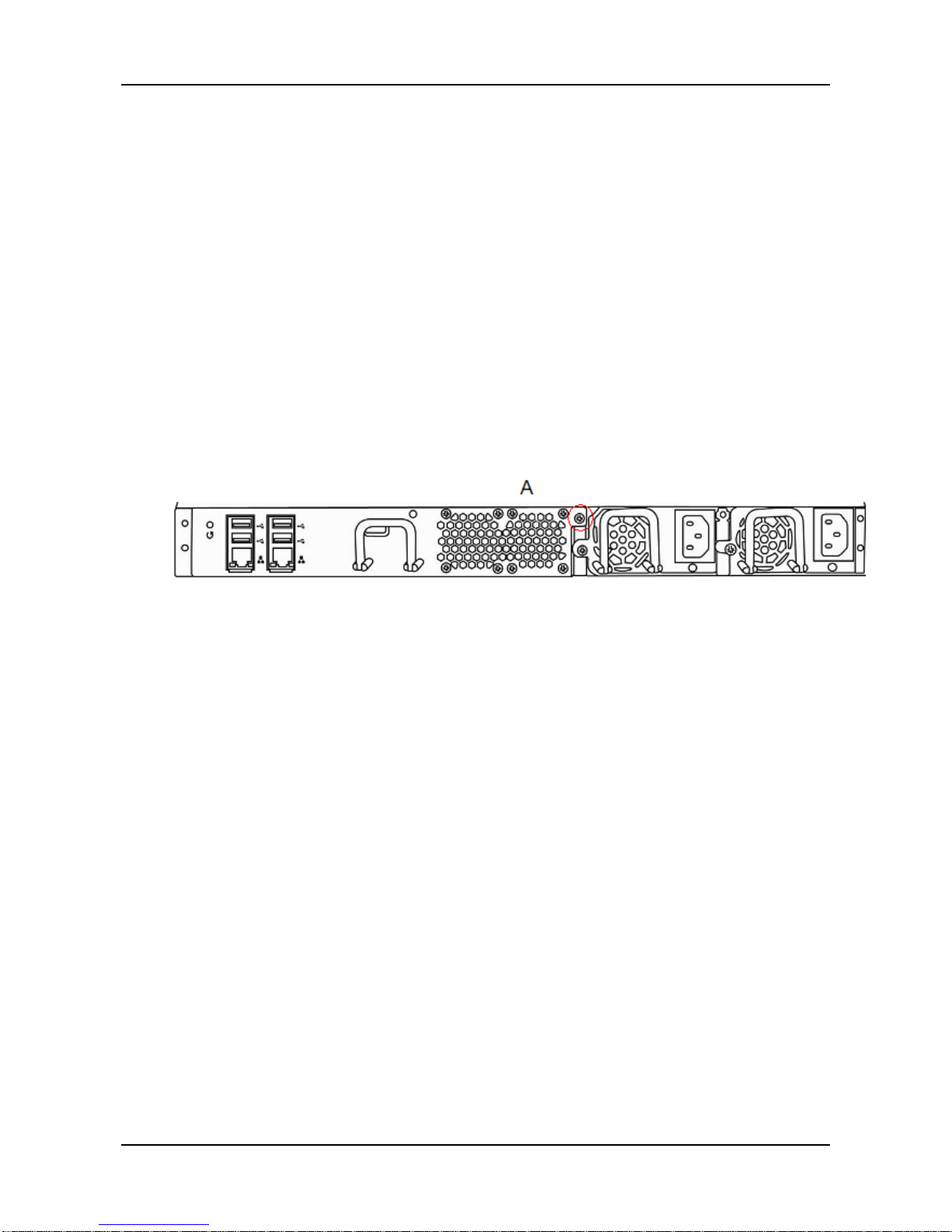
When the system controller malfunctions, you may replace the control
module as per following steps:
Step 1. Please turn off the system power.
Step 2. Loosen screw (A) on the control module.
Step 3. Remove the controller by pulling on the handle.
Step 4. Insert the new controller.
Step 5. Tighten screw (A).
Step 6. Reboot the system.
Page 20
ShareCenter Pro User Manual
20
Chapter 3: WebPAM PROe
3.1 Quick Start
The WebPAM PROe is factory-installed on the ShareCenter® Pro
DNS-1550-04 system. WebPAM PROe runs in the browser on your PC/Mac.
You can access WebPAM PROe by using your brows er.
Browser Support
Choose one of the following bro wser s to use with WebPAM PROe:
• Internet Explorer 7 or above
• Firefox 3 and above
• Safari 5 and above
• Google Chrome
Connecting to WebPAM PROe
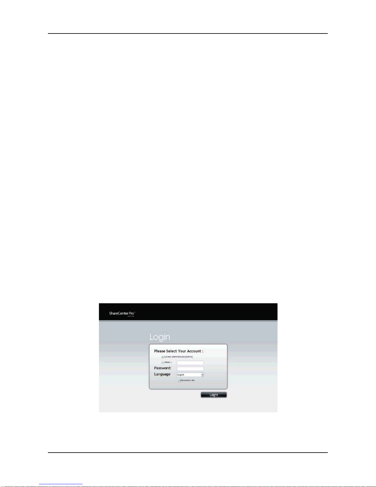
To log into WebPAM PROe from your browser:
1. Start your browser.
2. In the URL address bar, type in the IP address of the ShareCenter
®
Pro
DNS-1550-04. (Default IP Address: 192.168.0.32)
The WebPAM PROe login screen displays.
Page 21
21
3. The default user name is “administrator” and default password is
“password”
(The user name and password are case sensitive).
4. Choose the language you prefer by clicking the Language menu on the
login screen.
5. To log out of WebPAM PROe, you can do either of the following:
• Close your browser window.
• Click Logout in the WebPAM PROe Header.
Clicking Logout brings you back to the Login Screen. After logging out,
you must enter your user name and password in order to log in again.
Navigating in WebPAM PROe
The five tabs displayed on the screen are the primary navigation tools found
in WebP AM PROe. Categories of functions are listed below the icon found on
each tab.
Icons for specific functions are listed on each tab. Click the icon/tab to show
the functions offered.
Click the function's icon to display its information on the screen.
Page 22
ShareCenter Pro User Manual
22
3.2 Dashboard Tab
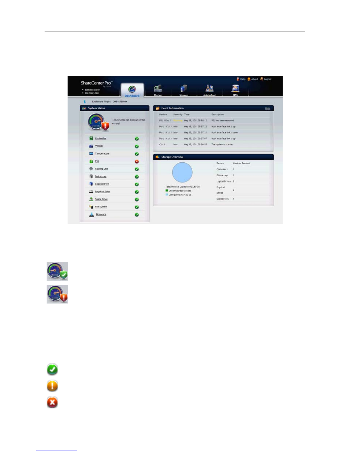
The Dashboard tab is the default screen of WebPAM PROe.
The System Status icon indicates the top-level status of the NAS by
displaying:
system is OK
system has errors
3.2.1 System Status
The System Status field displays the status of the NAS components by
means of the following icons:
the component is OK
the component needs attention
the component has failed
Page 23

23
To view the status of each component, click the following tab and topic
sequence. A status screen will then be displayed:
• Controller (RAID controllers)
Device tab > Component List.
• Voltage
Device tab > Component List.
• Temperature (RAID and JBOD enclosures only)
Device tab > Component List.
• PSU (Power supply unit. RAID and JBOD enclosures only .)
Device tab > Component List.
• Cooling Unit (RAID and JBOD enclosures only.)
Device tab > Component List.
• Disk Array
Storage tab > Disk Array.
• Logical Drive
Storage tab > Logical Drive.
• Physical Drive
Device tab > Physical Drive List.
• Spare Drive
Storage tab > Spare Drive.
• File System
NAS tab > File System.
• Firmware
AdminTool tab > Firmware Update.
3.2.2 Event Information
The Event Information field displays six of the most recent Runtime events.
Click More to display the AdminTool tab > Runtime Events screen, allowing
you to view all Runtime and NVRAM events.
3.2.3 Storage Overview
The Storage Overview field displays the general information of the current
storage status, including:
Page 24

ShareCenter Pro User Manual
24
• Total Physical Capacity. Display the total storage space of the
system.
− Unconfigured – not assigned to a logical dri ve.
− Configured – assigned to a logical drive.
• Device Number. Display the current number of devices in the
system.
Page 25
25
3.3 Device Tab
The Device tab displays the status of all devices in the NAS including
physical drives, disk arrays, logical drives, power supply units, fans and
backplanes.
In the Device tab, you can change settings for the enclosure and physical
drives.
3.3.1 Front View
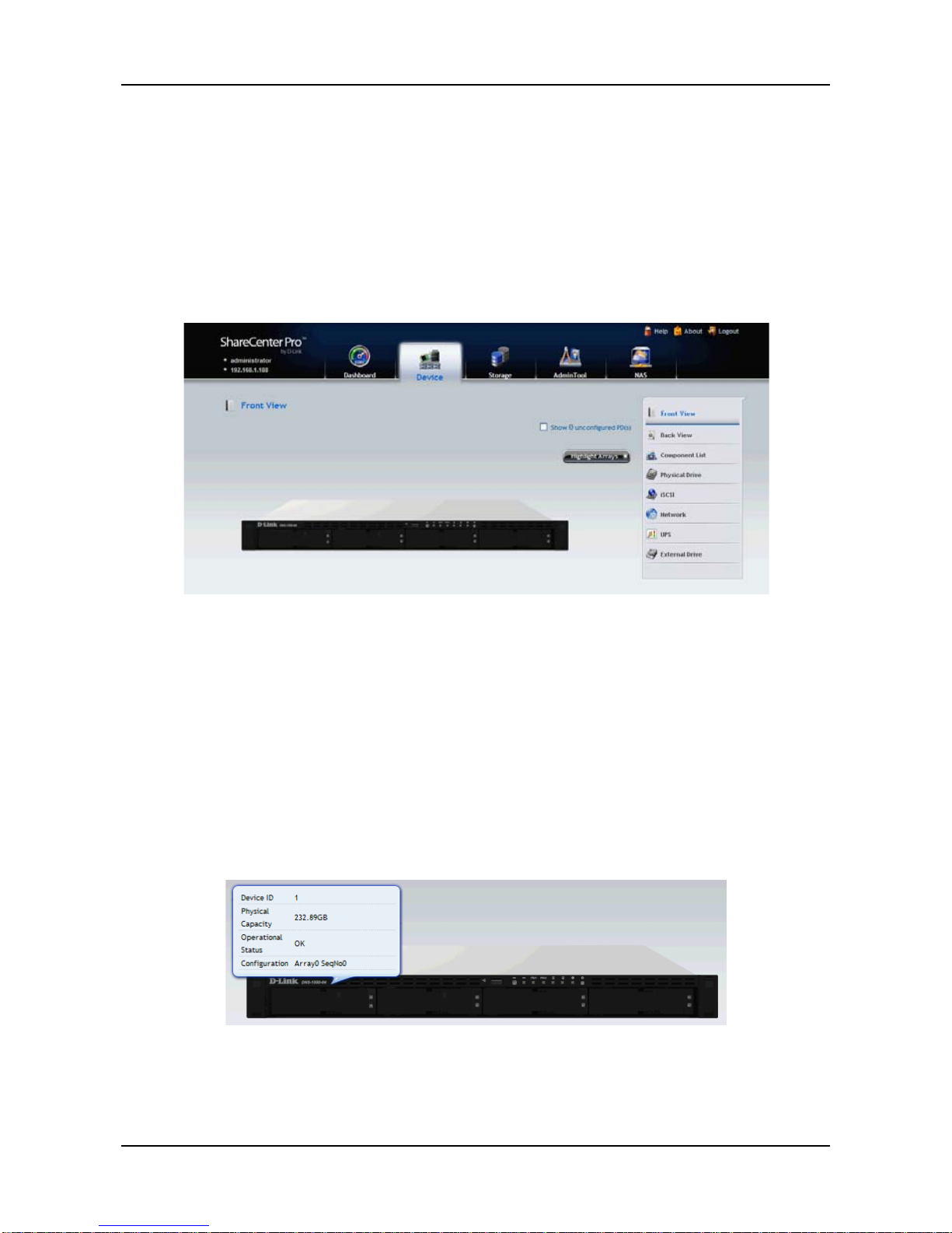
Click Device tab > Front View to view all of the enclosures found in your
NAS network. Move your mouse over the drive carrier to display the
information of the installed ph ys ical dri ve (as show below), including the
device ID, physical capacity, operational status, etc. Click on the drive to
bring up the Physical Drive Information, displaying the deta iled inf or mation of
the device.
Page 26
ShareCenter Pro User Manual
26
Identifying Unconfigured Physical Drives
Click the
Show unconfigured PD(s) box to identify the unconfigured
physical drives in the NAS.
Identifying Physical Drives Assigned to a Disk Array
Click the Highlight Arrays button to identify the physical drives assigned to a
disk array.
Click on of the following items in the dropdown menu:
• All DA – all disk arrays
• DA0 (DA1, DA2, etc.) – a specific disk array
• Close – click to close the menu and return to normal view.
The carriers containing drives that do not belong to the chosen disk array will
be highlighted.
3.3.2 Back View
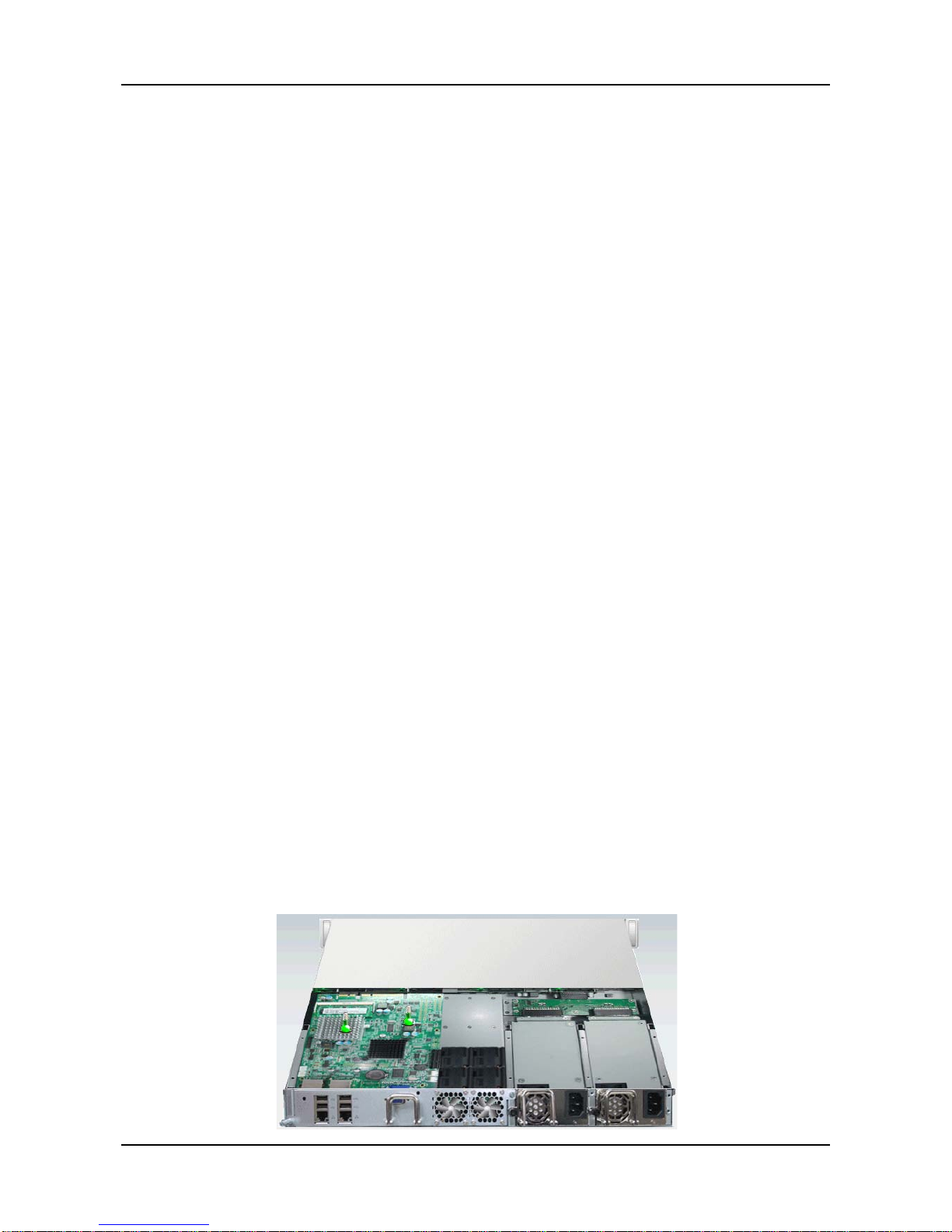
Click Device tab > Back View to display the back view of all enclosures in
the NAS. Move your mouse over the power supply and I/O units to view the
PSU status and the operational status of the devices through the I/O units.
Click Show Internal Components to display the virtual view of the internal
components (as shown below).
Move your mouse over the component and the related information will be
displayed:
• CPU – CPU usage
• Controll er thermometer – temperature of the controller board
• Temperature of the system
• RAM – memory usage
• Enclosure information
Page 27
27
3.3.3 Component List
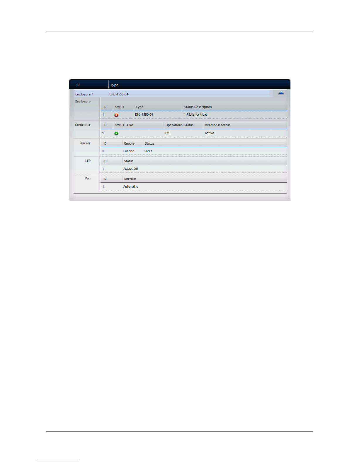
Click Device tab > Component List to display the device ID, operational
status, enclosure type, and status description of all enclosures.
• Enclosure
− View: Move your m ous e over the enclos ur e you want and
click the View button to display the enclosure information list.
− Setting: Set the system critical warming/critical temperature.
− Locate: The system will make a buzzing sound.
• Controller
− View: Move your mouse over the controller you want and click
the View button to display the controller information list.
− Setting:
1. Move your mouse over the controller you want and click
the Settings button.
2. Make setting changes as required:
− Enter, change or delete the alias in the Alias field
− Enable SMART Log – Check the box to enable or
uncheck to disable
− SMART Polling Interval – Enter a value into the field,
1 to 1440 minutes
− HDD Power Levels
Level 0: Disabled
Page 28

ShareCenter Pro User Manual
28
Level 1: Park R/W heads
Level 2: Slow down (need to be supported by hard
drive)
Level 3: Spin down
− Spin Down Type
− Power Sa ving Idl e Time
− Power Sa ving Sta ndby Tim e
− Power Sa ving Sto ppe d Time
− Enable Coercion:
This feature is designed for fault-tolerant logical
drives (RAID 0, 1, 5, 6, and 10). It is generally
recommended to use physical drives of the same
size in your disk arrays. When this is not possible,
physical drives of different sizes will work but the
system must adjust for the size differences by
reducing or coercing the capacity of the larger
drives to match the smaller ones. You can choose
to enable Capacity Coercion and any one of four
methods.
Capacity Coercion also affects a replacement
drive used in a disk array. Normally, when a
physical drive fails, the replacement drive must be
the same capacity or larger. However, the Capacity
Coercion feature permits the installation of a
replacement drive that is slightly smaller (within 1
gigabyte) than the remaining working drive. For
example, the remaining working drives can be
80.5GB and the replacement drive can be 80.3,
since all are rounded down to 80GB. This permits
the smaller drive to be used.
Without Capacity Coercion, the controller will not
permit the use of a replacement physical drive that
is slightly smaller than the remaining working
drives.
− Coercion Method – Choose a method from the
dropdown menu:
GB Truncate – (Default) Reduce the useful
Page 29

29
capacity to the nearest 1,000,000,000 byte
boundary.
10GB Truncate – Reduces the useful capacity to
the nearest 10,000,000,000 byte boundary.
Group Rounding – Uses an algorithm to
determine how much to truncate. Results in the
maximum amount of usable drive capacity.
Table Rounding – Applies a predefined table to
determine how much to truncate.
− Write Back Cache Flush Interval – Enter a value into
the field, 1 to 12 seconds
− Phydrv Driver Temperature Threshold
− Enclosure Polling Interval
− Adaptive Writeback Cache:
UPS power good: write bac k
UPS power fail: write through
No UPS: write through
− Host Cache Flushing
− Forced Read Ahead (cache) – Check the box to
enable or uncheck to disable
3. Click the Save button.
• Buzzer
− Click the Sound button to unmute the buzzer; or click the
Mute button to mute the buzzer.
− Click the Settings button to enable or disable the buzzer.
To enable the buzzer for the system, select the Enable
Buzzer option and click the Save button. To mute the buzzer
for all events, you must clear the Enable Buzzer option.
• LED. Move your mouse over the LED and click the Settings button,
which allows you to set the LED by selecting :
− Always ON
− Always OFF
− Daily
• Fan. Move your mouse over the Fan and click the Settings button,
which allows you to set the LED by selecting :
Page 30
ShareCenter Pro User Manual
30
− Manual
− Automatic
When done, click the Save button.
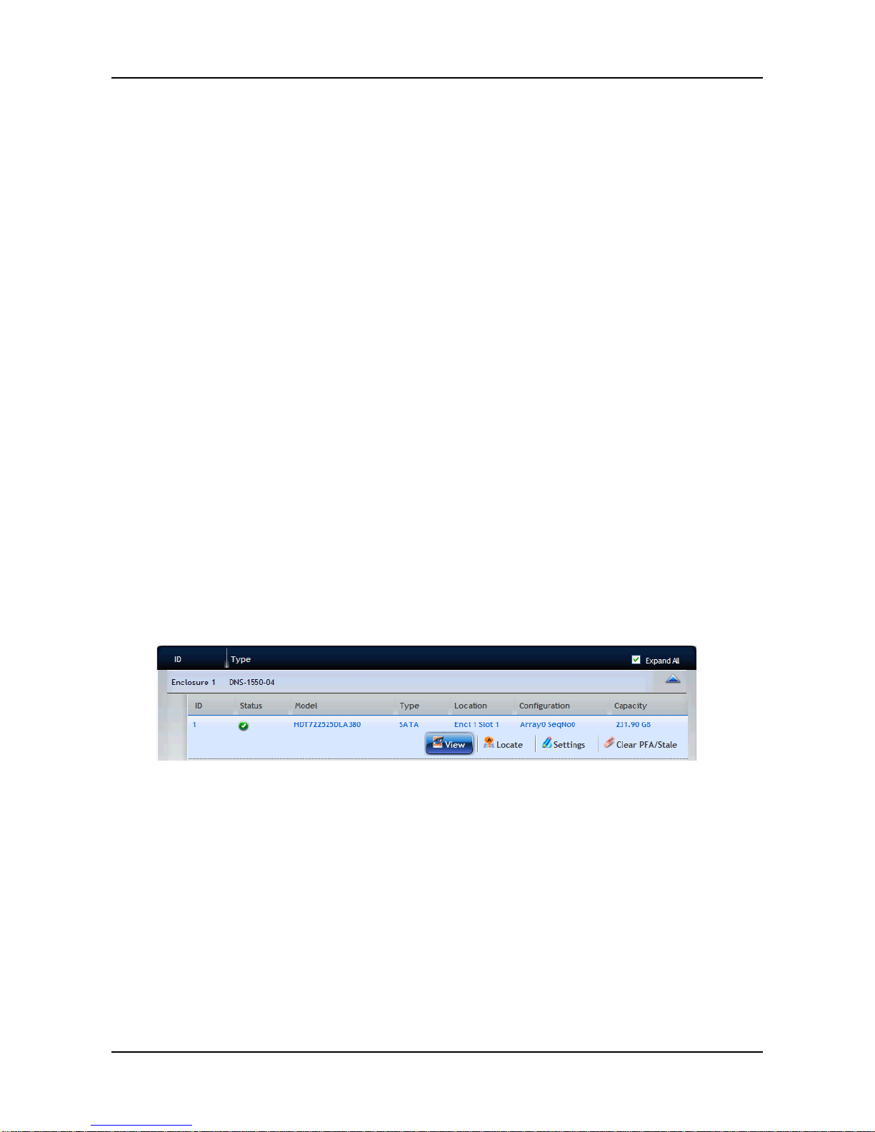
3.3.4 Physical Drive
Click Device tab > Physical Drive to display the list of physical drives in the
NAS. Physical drive information includes:
− ID – ID number of the physical drive
− Status – Green, yellow, and red icons
− Model – Make and model of the drive
− Type – SATA HDD
− Location – Enclosure number and slot number
− Configuration – Array number and sequence number, spare
number, unconfigured, or stale configuration
− Capacity – The capacity of drive
Viewing Physical Drive Information
1. Click Device tab > Physical Drive.
2. Move you mouse over the physical drive you want and click the View
button.
Display all Physical drive in f ormation.
To locate the physical drive:
1. Click Device tab > Physical Drive.
2. Move your mouse over the physical drive you want and click the
Locate
button.
3. The drive carrier LEDs blink for one minute.
To change the global physical drive settings:
1. Click Device tab > Physical Drive.
2. Click the G lob al Ph ysical Driv e Settings button.
Page 31

31
3. In the Global Physical Dr ive Settings window, check the boxes to enable
or uncheck to disable.
Enable Write Cache
Enable Read Look Ahead Cache
Enable Command Queuing
To change the individual physical drive settings:
1. Click Device tab > Physical Drive.
2. Move your mouse over the physical drive you want and click the
Settings button.
3. Make setting changes as required: enter, change, or delete the alias in
the Alias field.
4. Click the Save button.
Physical Drive Problem s:
Physical dri ves are the foundation of data storage. A physical drive Problem
can affect your entire NAS. When a yellow icon or a red icon
appears beside a physical drive, check the drive's operational status:
1. Click Device tab > Physical Drive.
2. Move your mouse over the physical drive you want and click the
View
button.
3. Check the status of the Operational Status item.
3.3.5 iSCSI
Click Device tab > iSCSI to display the iSCSI (Internet Small Computer
System Interface) information in the system. iSCSI information includes the
following tabs:
− Node
− Portal
− Port
− Session
Page 32
ShareCenter Pro User Manual
32
− iSNS
− CHAP
− Ping
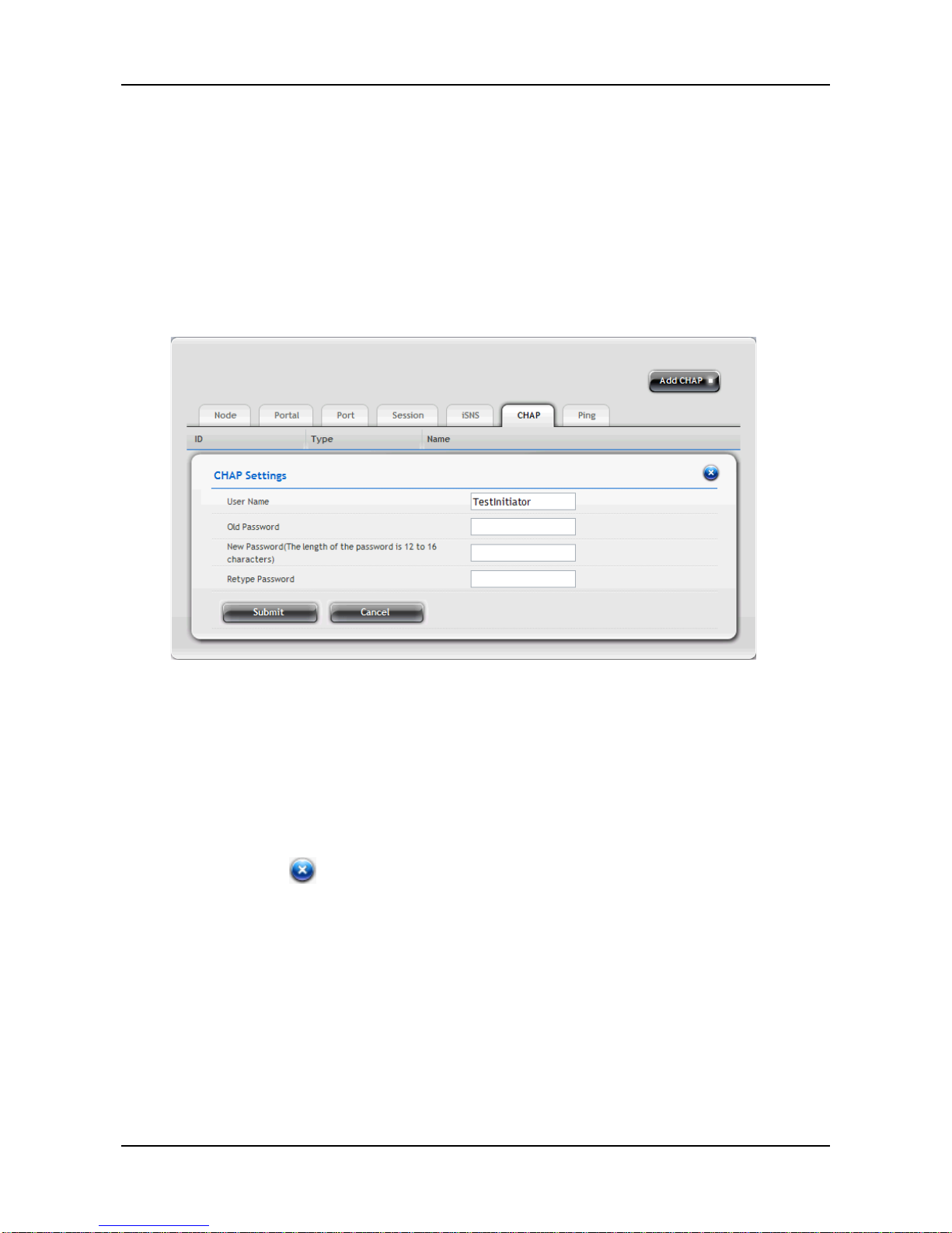
Setting up CHAP
1. Click Device tab > iSCSI > CHAP tab.
2. Move your mouse over the item you want and click the Setting button.
3. Complete the required settings in the Chap Settings window, and then
click the Submit button.
− User Name
− Old Password
− New Password
− Retype Password
Click the button to close the dialog window.
Page 33
33
3.3.6 Network
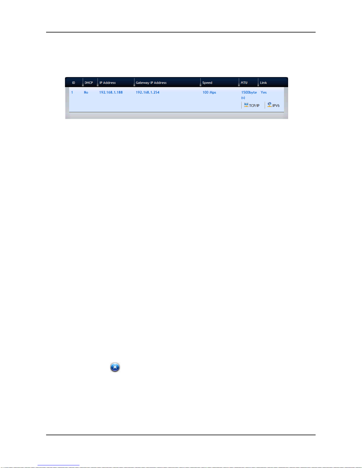
Click Device tab > Network to display the networking information of the
system.
Networking information includes:
− ID
− DHCP
− IP Address
− Gateway IP Address
− Speed
− MTU
− Link
Changing Networking Configuration
1. Click Device tab > Network.
2. Move your mouse over the network you want and click the TCP/IP (or
IPV6) button.
3. Complete the required settings in the dialog window, and then click the
Submit button.
− Network Speed – Select the networking speed from the menu.
− IP Properties
− IP Address
− Subnet Mas k
− Gateway IP Address
− DNS Server IP Address
− Secondary DNS Server IP Address
Click the button to close the dialog window.
Page 34
ShareCenter Pro User Manual
34
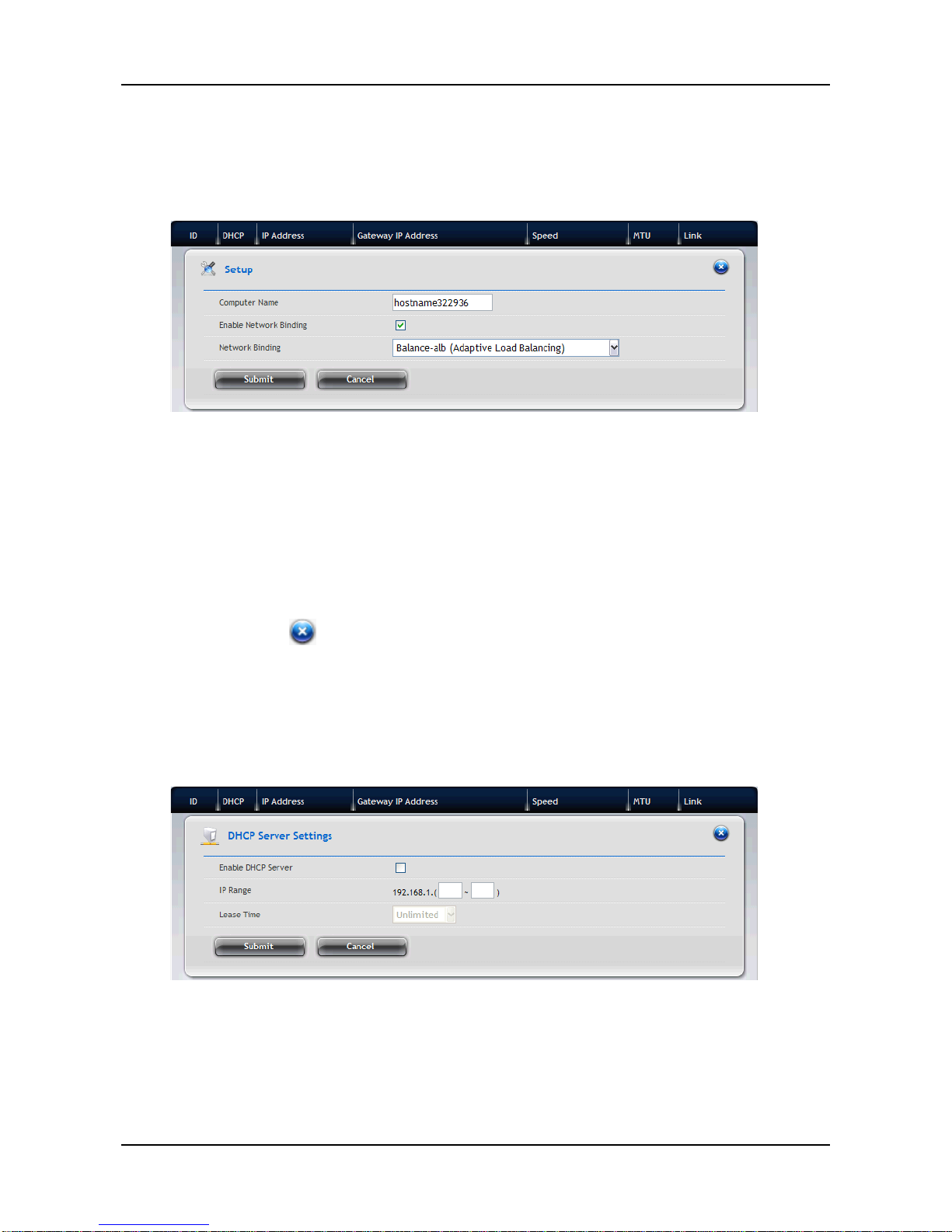
Advanced Networking Configuration
1. Click Device tab > Network.
2. Click the Setup button.
3. Complete the required settings in the Setup window, and then click the
Submit button.
− Computer Name
− Enable Network Binding – Choose to enable or disable a
biding.
− Net work ing Bin ding – From the dropdown menu, choose a
Proper biding type.
Click the button to close the dialog window.
Setting up DHCP Server
1. Click Device tab > Network.
2. Click the DHCP Server button.
Page 35
35
3. Complete the required settings in the DHCP Server Settings window,
and then click the Submit button.
− Enable DHCP Server – Choose to enable or disable the
function.
− IP range – Assign the IP range in the text boxes.
− Lease Time
Click the button to close the dialog window.
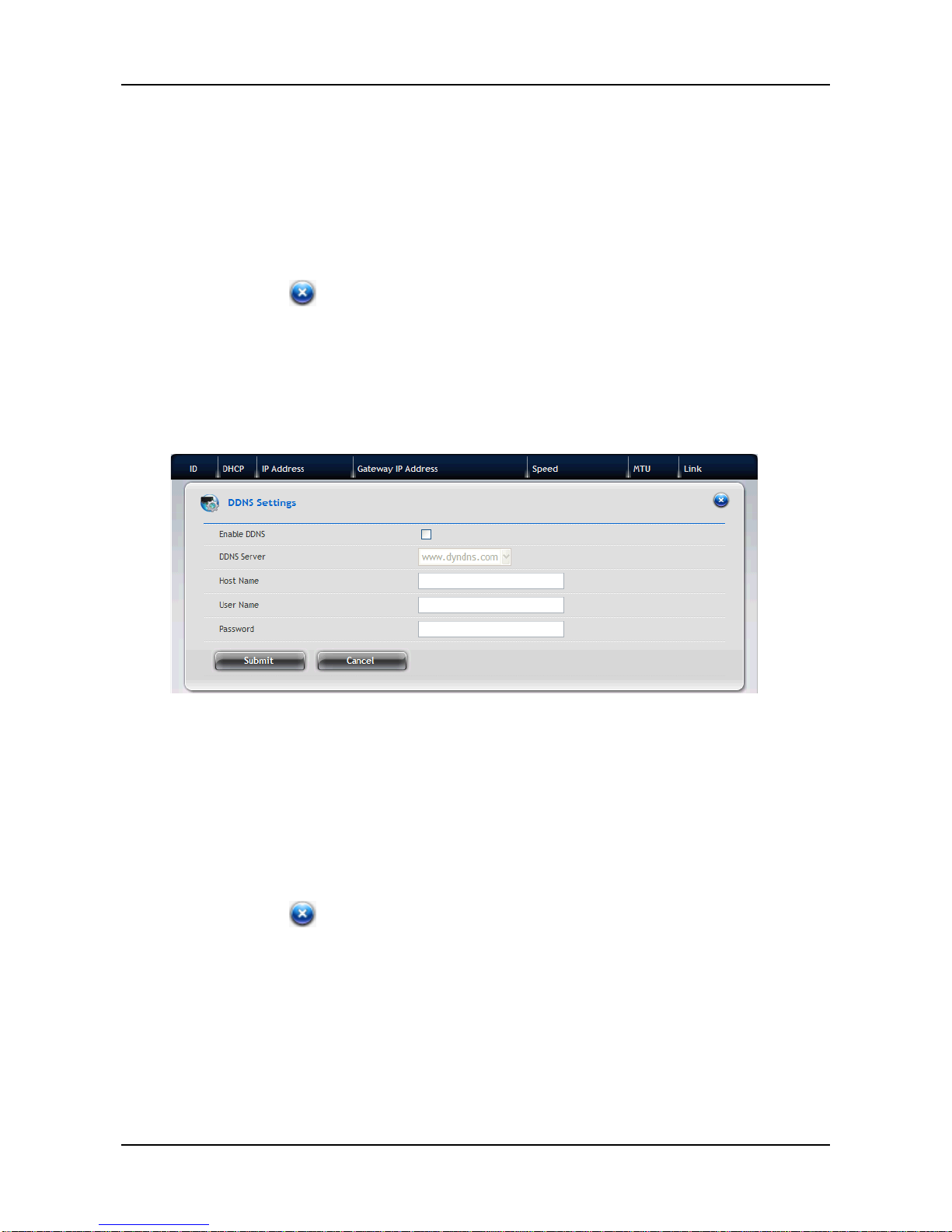
Setting up DDNS
1. Click Device tab > Network.
2. Click the DDNS button.
3. Complete the required settings in the DDNS Settings window, and then
click the Submit button.
− Enable DDNS – Choose to enable or disable the function.
− DDNS Server – Enter the address of the DDNS server.
− Host Name – Enter the host name of the DDNS server.
− User Name – Enter the user name to login the DDNS server.
− Password – Enter the password to login the DDNS server.
Click the button to close the dialog window.
Page 36
ShareCenter Pro User Manual
36
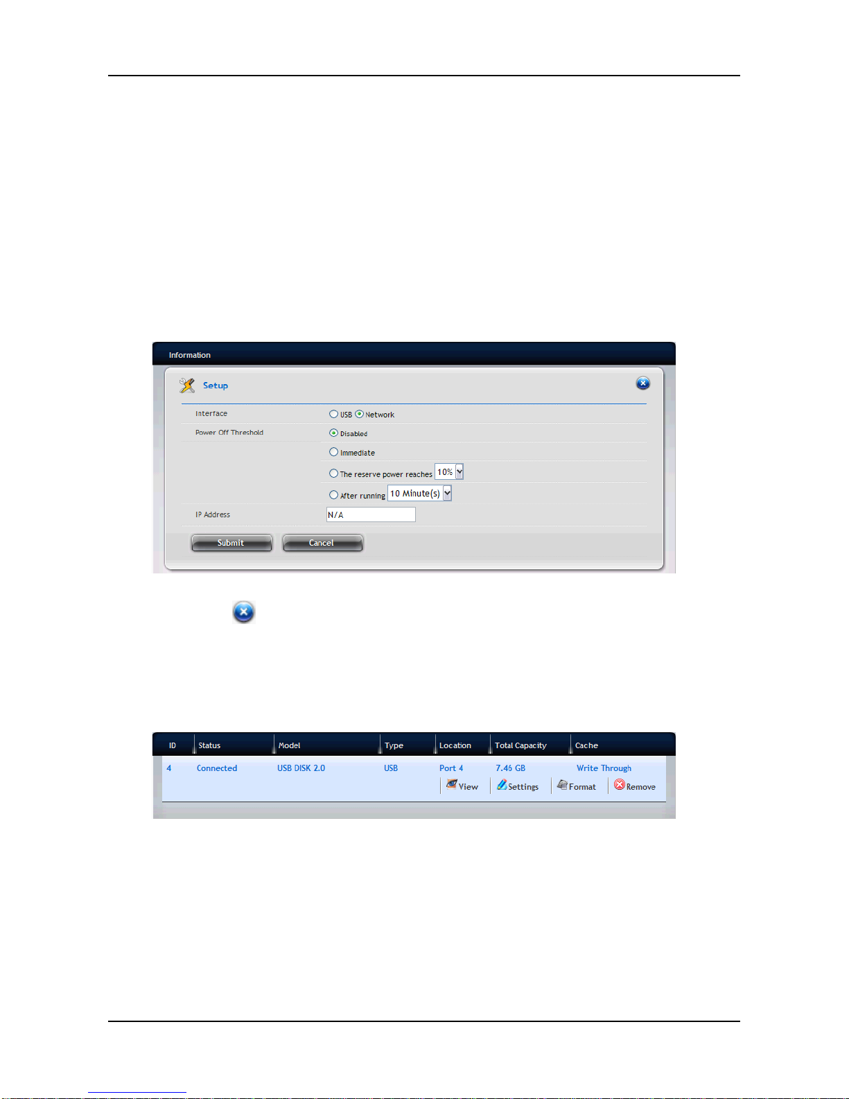
3.3.7 UPS
Click Device tab > UPS to dis pla y the information of the connected UPS in
the system.
Setting up UPS
1. Click Device tab > UPS.
2. Click the Setup button to bring up the Setup window.
3. Select the option you want and complete the required settings, and then
click the Submit button.
Click the button to close the dialog window.
3.3.8 External Drive
Click Device tab > External Drive to display the information of the connected
external drive in the system.
External drive information includes:
− ID
− Status
− Model
− Type
− Location
− Total Capacity
Page 37

37
− Cache
ShareCenter Pro DNS-1550-04 can support external file system as below:
EXT3, XFS,FAT32, NTFS,HFS+
Warning!
To remove the connected USB drive safely, you MUST click the Remove
button before disconnecting the USB drive.
Managing the External Drive
1. Click Device tab > External Drive.
2. Move your mouse over the external drive you want, and then you can do
one of the following:
− Click the Settings button and select the Write Policy (Write
Through or Write Back), and then click the Save button to
configure the external drive.
− Click the Format button and select the format type (FAT32,
ntfs, or xfs), and then click the Format button to format the
external drive.
− Click the Remove button and click the Confirm button to
remove the external drive.
Click the button to close the dialog window.
Page 38
ShareCenter Pro User Manual
38
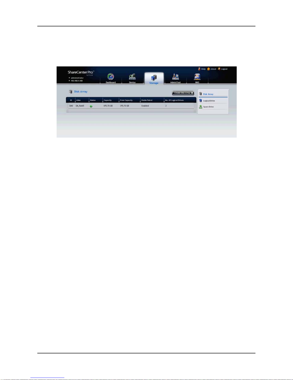
3.4 Storage Tab
The Storage tab enables you to create, manage, and delete disk arrays,
logical drives, and spare drives.
The list of Disk Array Provides the information of the disk array, including:
− ID – DA0, D A1, DA2, etc .
− Alias – If assigned.
− Status – Green, yellow or red icon.
− Capacity – Data capacity of the disk array.
− Free Capacity – Unconfigured or unused capacity on the
physical drives.
− Media Patrol – Enabled or disabled on this disk array.
− No. Of Logical Drives – The number of logical drives on this
disk array .
To initialize the Dsk Array:
Initialization is normally done to logical drives after they are created from a
disk array . Initialization sets all data bits in the logical drive to zero. The action
is useful because there may be residual data on the logical drives left behind
from earlier configurations. For this reason, Initialization is recommended
whenever you create a logical drive.
Step 1. Create Disk Array. Refer to the instructions in section 3.4.1.
Step 2. Create Logical Drive. Refer to the instructions in section 3.4.4.
Step 3. Create File System.
Page 39
39
Warning!
When you initialize a logical drive, all the data on the logical drive is lost.
Backup any important data before you initialize a logical drive.
3.4.1 Create Disk Array
You can also use the Wizard to create a disk array with logical drives and
spare drives at the same time.
To create a disk array:
1. Click Storage tab > Disk Array.
2. Click the Create Disk Array button.
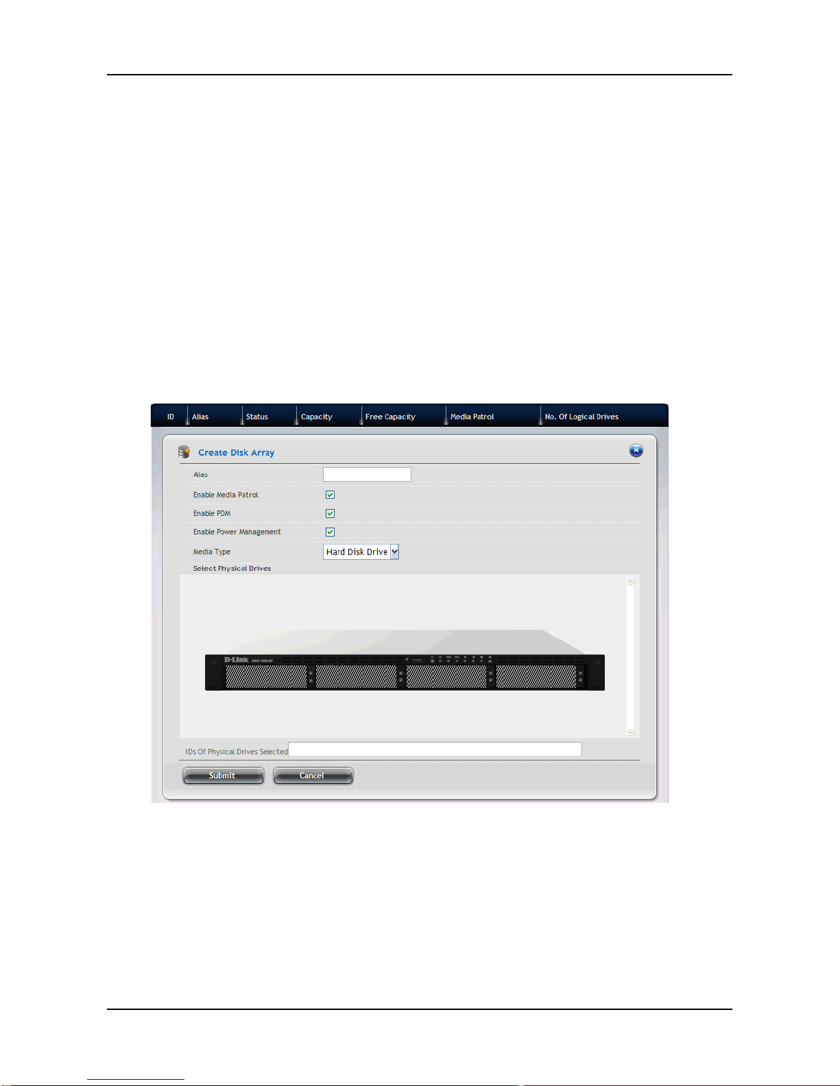
3. In the Create Disk Array window, complete the required settings:
− In the Alias field, enter an alias at a maximum of 32
characters (includes letters, numbers, space between
characters, and underline).
− Select the Enable Media Patrol option to enable the function
on this disk array; otherwise, clear this option to disable.
− Select the Enable PDM option to enable the function on this
disk array; otherwise, clear this option to disable.
− Select the Enable Power Management option to enable the
Page 40
ShareCenter Pro User Manual
40
function on this disk array; otherwise, clear this option to
disable.
4. In the Select Physical Drives diagram, click the drives to add them to
your disk array. The ID numbers of the selected drives will appear in the
field below the diagram.
5. When done, click the Submit button. The new disk array appears in the
list.
6. Do one of the following:
− To create additional disk arrays, click the Create More button.
− If you are done creating disk arrays, click the Finish button.
After creating a disk array, you need to create a logical drive on it. Follow the
steps below to create a logical drive:
1. Click Storage tab > Logical Drive.
2. Click the Create Logical Drive button.
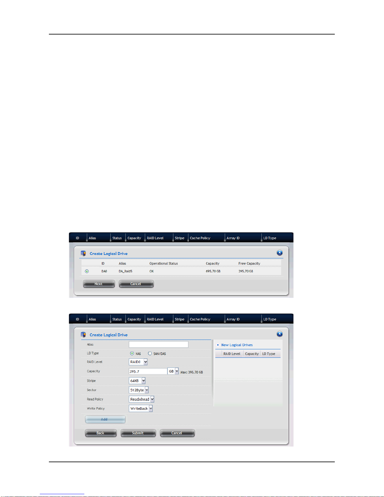
3. Select the disk array you want to use and click the Next button.
4. In the Create Logical Drive window, complete the required settings:
Page 41
41
− In the Alias field, enter an alias at a maximum of 32
characters (includes letters, numbers, space between
characters, and underline).
− Set the LDType as NAS or SAN/DAS.
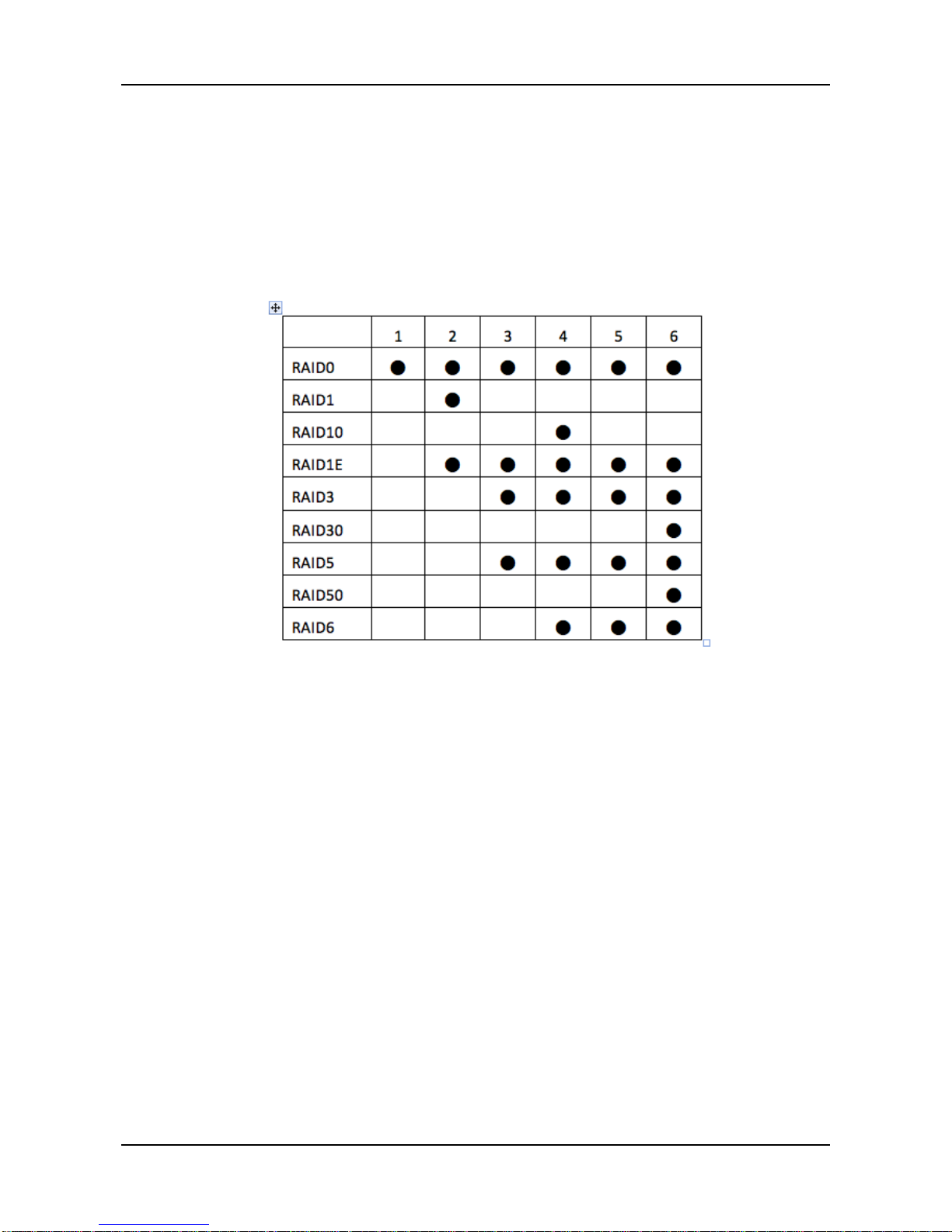
− Select a RAID Level from the dropdown menu, depending on
the number of physical drives in the disk array.
Support RAID type with drive number
− In the Capacity field, accept the default maximum capacity or
enter a lesser capacity (size in MB, GB or TB). Any remaining
capacity is available for an additional logical drive.
− Choose the Stripe size: 64 KB, 128 KB, 256 K B, 512 K B, or 1
MB.
− Choose the Sector size: 51 2 B, 1 KB, 2 KB, o r 4 KB.
− Choose the R ead Policy: Read Cache, Read Ahead, or No
Cache
− Choose the Write Po licy: Write Back or Write Through.
5. Click the Add button. The new logical drive appears in the New Logical
Drives list.
If there is capacity remaining, you can create an additional logical drive.
6. When done, click the Submit button. The new logical drive(s) will appear
in the Logical Drive list.
New logical drives are automatically synchronized. You can access the
logical drive during synchr o ni zat ion.
Page 42

ShareCenter Pro User Manual
42
Disk Array Problems:
Disk array Problems typically result from a physical drive failure. The most
common Problem is a degraded disk array. The RAID controller can rebuild a
degraded disk array.
A more serious, but far less common Problem is an Incomplete Array. An
incomplete array results from a physical drive that fails or becomes missing
during:
− RAID level migration
− Disk array transport
Disk Array Degraded:
Disk arrays are made up of physical drives. Logical drives are created on the
disk array . When one of the physical drives in a disk array fails:
− The operational status of disk array becomes Degraded.
− The operational status of logical drives becomes Critical.
− The operational status of physical drive becomes Dead or
Offline.
Disk Array Offline :
Disk arrays are made up of physical drives. Logical drives are created on the
disk array . When a disk array and its logical drives go Offline, the data stored
in the logical drives is no longer access ib le.
− Logical drives based on fault-tolerant disk arrays — RAID 1, 5,
6 and 10,— go Offline when two physical drives are removed
or fail.
− Logical drives based on non-fault tolerant disk arrays — RAID
0 — go Offline when a one physical drive is removed or fails.
Page 43
43
3.4.2 Disk Array Management
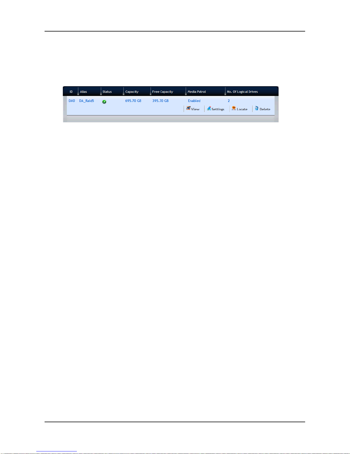
1. Click Storage tab > Disk Array. The list of disk arrays appears.
2. Move your mouse over the disk array you want to display the options of
the disk array, including:
− View – Select to view disk array status in the Information tab:
Disk Array ID – DA0, DA1, DA2, etc.
Alias – If assigned
Operational Status – OK is normal
Media Patrol – Enabled or disabled on this arr a y
PDM – Enabled or disabled on this array
Power Management
Total Physical Capacity – Data capacity of the array
Configurable Capacity – Maximum usable capacity of the
array
Free Capacity – Unconfigured or unused capacity on the
physical drives
Max Contiguous Free Capacity – Unconfigured or unused
capacity in contiguous sectors on the physical drives
Number of Physical Drives – The number of physical
drives in this array
Number of Logical Drives – The number of logical drives
on this array
− Settings – Select to change or delete the alias in the Alias
field. Also, you can enable or disable Media Patrol, PDM, and
Power Managem ent. When done, click the Save button.
− Locate – This feature causes the drive carrier’s LED to blink
for one minute to assist you in locating the physical drives that
make up this disk array.
− Delete – Select and click the Confirm button to delete a disk
array.
Page 44
ShareCenter Pro User Manual
44
CAUTION: IF YOU DELETE A DISK ARRAY, YOU ALSO DELETE LOGICAL
DRIVES THA T BELONG TO IT, ALONG WITH THE DA TA IN THOSE
LOGICAL DRIVES. BAC K UP IMPORTANT DATA BEFORE DELETING A
DISK ARRA Y.
3.4.3 Logical Drive Management
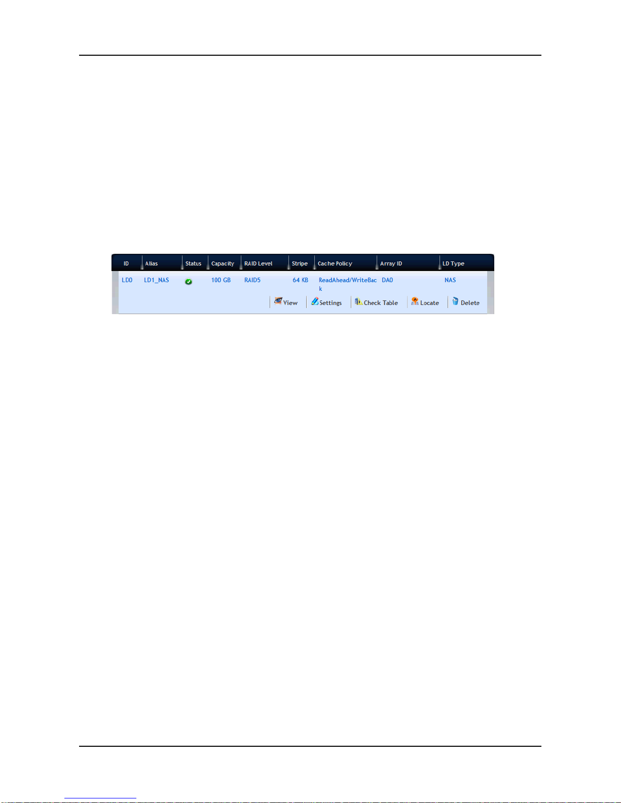
1. Click Storage tab > Logical Drive. The list of logical drives appears.
2. Move your mouse over the logical drive you want to display the options
of the logical drive, including:
− View – Select to view logical drive status:
Disk Array ID – LD0, LD1, LD2, etc.
Alias – If assigned
Array ID – ID number of the disk array where this logical
drive was created
RAID Level – Set when the logical drive was created
Operational Status – OK means normal
Capacity – Data capacity of the logical drive
Number of Axles – For RAID 10, 2 axles. For RAID 50 and
60, 2 or more axles
Physical Capac ity – Data capacity of the physical drives
Number of Physical Drives – The number of physical
drives in the disk array
Stripe size – Set at logical drive creation
Read Policy – Adjustable
Sector size – Set at logical drive creation
Write Policy – Adjustable
Tolerable Number of Dead Drives – Number of physical
drives that can fail without the logical drive going offline
Synchronized – A new logical drive shows "No" until
synchronizing is completed
Parity Pace – Pertains to some RAID levels
Page 45

45
WWN – World Wide Number, a unique identifier assigned
to this logical drive
Codec Scheme – Pertains to some RAID levels
Serial Number – Assigned to this logical drive
ALUA Access State For Ctrl1
ALUA Access State For Ctrl2
LDType – Displays the LD type of the logical drive.
− Settings – Select to change or delete the alias in the Alias
field. Also, you can configure the Read Policy (ReadCache,
ReadAhead, or NoCache) and Write Policy (WriteThru or
WriteBack). When done, click the Save button.
− Check Table – Displays the error tables. Use this information
to evaluate the integrity of the logical drive and to determine
whether corrective action is needed.
All – All errors. The default choic e.
Choose an option:
Read Check – Read errors for this logical drive.
Write Check – Write errors for this logical drive.
Inconsistent Block – Inconsistent blocks for this logical
drive. Mirror data for RAID Levels 1, 1E and 10 or Parity
data for RAID Levels 5, 6, 50, and 60. Identified by the
Redundancy Check.
Entry Number – A number assigned to each block of entry.
The Check T able lists:
Table Ty pe – Read Check, Write Check or Inconsistent
Block.
Starting Logical Block Address – LBA of the first block for
this entry .
Count – Number of errors or continuous blocks starting from
this LBA.
− Locate – This feature causes the drive carrier’s LED to blink
for one minute to assist you in locating the physical drives that
make up this disk array.
− Delete – Select and click the Confirm button to delete a
logical.
Page 46
ShareCenter Pro User Manual
46
CAUTION: IF YOU DELETE A LOGICAL DRIVE, YOU ALSO DELETE ALL
THE DATA IN THE LOGICAL DRIVE. BACK UP IMPORTANT DATA
BEFORE DELETING A LOGICAL DRIVE.
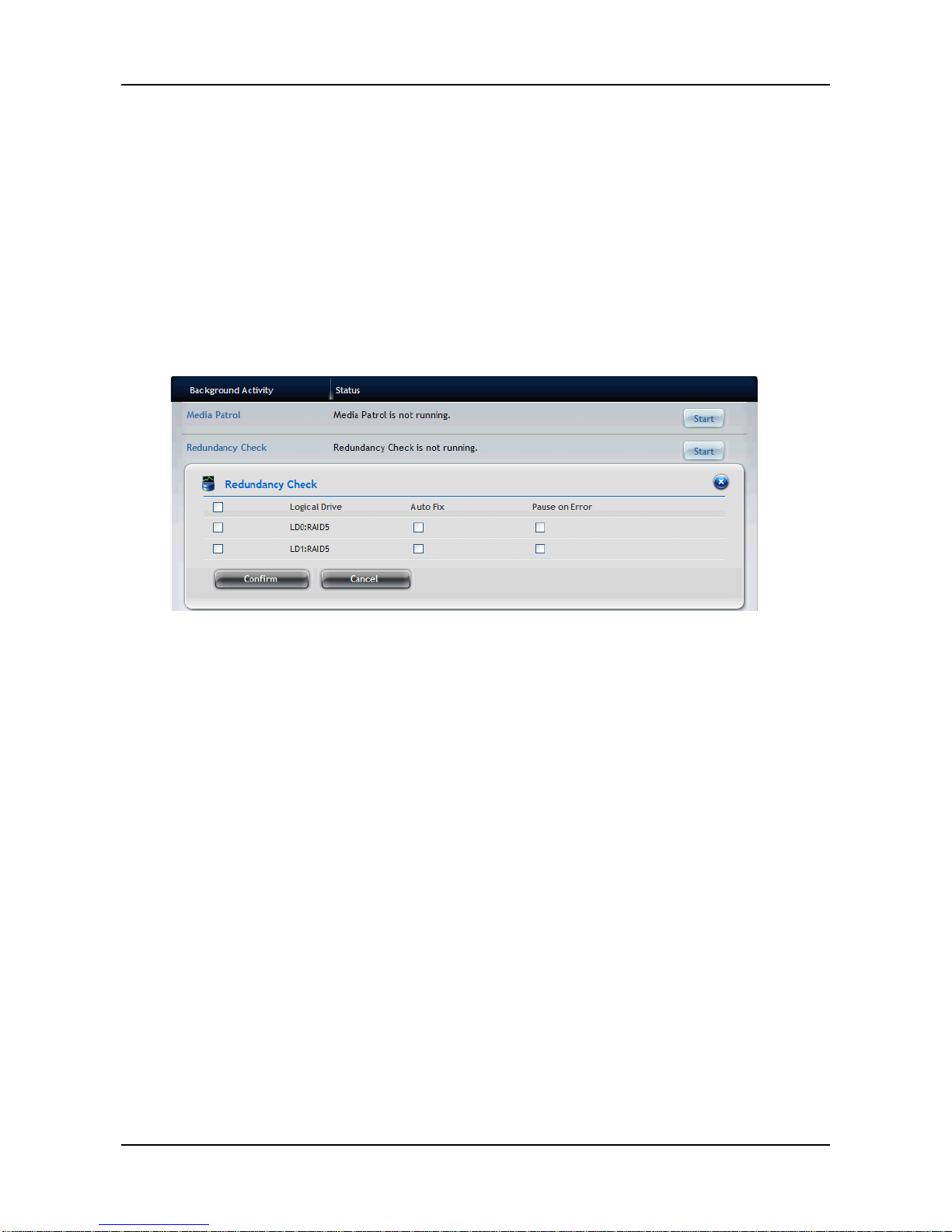
To run Redundancy Check on a logical drive:
1. Click AdminTool tab > Background A cti vity. The list of back gr ound
activities appears.
2. Move your mouse over the Redundancy Check item and click the Start
button.
3. Check the boxes to the left of the logical drives you want to run.
4. Check the options you want:
− Auto Fix – Attempts to repair the Problem when it finds an
error
− Pause on Err or – The Process stops when it finds a
non-repairable error
5. Click the Confirm button.
To change the Synchronization settings:
1. Click AdminTool tab > Background Ac tivity.
2. Click the Settings button.
3. Click the Background Synchronization Rate dropdown menu and
choose a rate:
− Low – Fewer system resources to Synchronization, more to
data read/write operations.
− Medium – Balances system resources between
Synchronization and data read/write operations.
Page 47

47
− High – More system resources to Synchronization, fewer to
data read/write operations.
4. Click the Confirm button.
Logical Drive Problems:
Logical drive Problems typically result from a physical drive failure. The most
common Problem is a critical logical drive. The RAID controller can rebuild a
critical logical drive.
A more serious but far less common Problem is an Incomplete Array. An
incomplete disk array results from a physical drive that fails or becomes
missing during:
− RAID level migration
− Physical drive transport
3.4.4 Spare Drive Management
If you have an unassigned disk drive, you can assign it as a spare drive. A
spare is a disk drive that has been designated to replace a failed disk drive in
a RAID Volume. In the event of the failure of a disk drive within a RAID 1 or
three drive RAID 5 Volume, the spare drive is activated as a member of the
RAID Volume to replace a disk drive that has failed.
A spare drive cannot replace the failed drive in a RAID 0 Volume because of
the way in which data is written to the disk drives under RAID 0. A spare drive
is not available for a RAID 10 Volume because RAID 10 requires all four disk
drives in the ShareCenter
®
Pro DNS-1550-04 enclosure. However, when you
replace the failed disk drive, the ShareCenter
®
Pro DNS-1550-04 wi ll
automatically rebuild the RAID Volume using the new disk drive.
To assign a spare drive:
1. Click Storage tab > Spare Drive. The list of spare drives appears.
2. Move your mouse over the spare drive you want to display the options of
the spare drive, including:
− ID
Page 48

ShareCenter Pro User Manual
48
− Status – Green, yellow or red icon.
− Capacity – Data capacity of the spare drive.
− Physical Drive ID
− Revertible
− Type
− Dedicated to Array
3. When done, click the Confirm button.
Page 49
49
3.5 AdminTool Tab
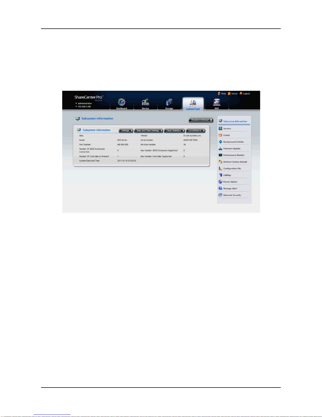
The AdminTool tab enables you to manage the Subsystem NAS system or
virtual enclosure, monitor events, manage background activities, perform
firmware updates, restore factory default settings, and save a NAS
configuration report.
3.5.1 System settings and clearing statistics
The list of NAS system information, including:
− Alias, if assigned
− Vendor
− Model
− Serial Number
− Part Number
− Revision Number
− Number of JBOD Enclosures Connected
− Max Number JBOD Enclosures Supported
− Number of Controller(s) Present
− Max Number Controller Supported
− System Date & Time
Page 50

ShareCenter Pro User Manual
50
To change the Subsystem settings;
1. Click AdminTool tab > Subsystem Information. The list of system
information
2. Click the Settings button.
3. In the Alias field, enter an alias or change the existing alias.
4. When done, click the Save button.
To restart/shutdown the Subs ystem:
1. Click AdminTool tab > Subsystem Informatio n.
2. Click the Shutdown/Restart button.
3. In the Shutdown/Restart window, you can:
− Click the Shutdown button to stop I/Os and shuts down the
subsystem. After subsystem shutdown, you must manually
switch off the power at both power supplies.
− Click the Restart button to stop I/Os, shuts down and restarts
the subsystem.
− Click the Power Off button to turn off the system power. After
power off, the power cord(s) has to be removed then plugged
in to get Redundant PSU working again.
You can clear the physical drive, logical drive, and controller statistics by
following the steps below:
1. Click the AdminTool tab > Subsystem Information. The list of system
information.
2. Click the C le ar Stat isti cs button.
3. When done, click the Confirm button.
Page 51
51
3.5.2 Services
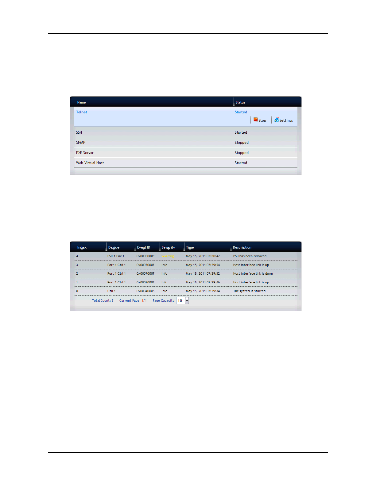
To start a service on the ShareCenter® Pro DNS-1550-04:
1. Click the AdminTool tab > Service. The list of services displays.
2. Move your mouse over the service you want and click the Start button.
3. Click the Confirm button.
3.5.3 Runtime and NVRAM event logs
Runtime events are the 1023 most recent events since the last NAS startup.
To view runtime events, click the AdminTool tab > Events.
The list of Runtime Events displays the information, including:
− Index – A number assigned to this specific event. Highest
number is most recent.
− Device – Identifies the device involved.
− Event ID – Identifies the action that occurred.
− Severity – Displays the Severity Level: Info, Minor, Major,
Warning, Critical, or Fatal.
Fatal – Non-Recoverable error or failure has occurred.
Critical – Action is needed now and the implications of the
condition are serious.
Major – Action is needed now.
Minor – Action is needed but the condition is not a serious
Page 52

ShareCenter Pro User Manual
52
at this time.
Warning – User can decide whether or not action is
required.
Info – Information only, no action is required.
− Time – Date and time the event occurred.
− Description – Plain language description of the event.
The device also Provides NVRAM event logs. NVRAM events are the most
important events over NAS startups.
To view NVRAM events:
1. Click the AdminTool tab > Events.
2. Click the NVRAM Events button. The list of NVRAM Events displays the
information, including:
− Index – A number assigned to this specific event. Highest
number is most recent.
− Device – Identifies the device involved
− Event ID – Identifies the action that occurred
− Severity – Displays the Severity Level: Info, Minor, Major,
Warning, Critical, or Fatal.
Fatal – Non-Recoverable error or failure has occurred.
Critical – Action is needed now and the implications of the
condition are serious.
Major – Action is needed now.
Minor – Action is needed but the condition is not a serious
at this time.
Warning – User can decide whether or not action is
required.
Info – Information only, no action is required.
− Time – Date and time the event occurred
− Description – Plain language description of the event
To view Runtime events:
1. Click the AdminTool tab > Events.
2. Click the Runtime Events button. The list of Runtime Events displays
the information, including:
Page 53

53
− Index – A number assigned to this specific event. Highest
number is most recent.
− Device – Identifies the device involved
− Event ID – Identifies the action that occurred
− Severity – Displays the Severity Level: Info, Minor, Major,
Warning, Critical, or Fatal.
Fatal – Non-Recoverable error or failure has occurred.
Critical – Action is needed now and the implications of the
condition are serious.
Major – Action is needed now.
Minor – Action is needed but the condition is not a serious
at this time.
Warning – User can decide whether or not action is
required.
Info – Information only, no action is required.
− Time – Date and time the event occurred
− Description – Plain language description of the event
To clear the NVRAM/Runtime event log:
1. Click the AdminTool tab > Events.
2. Click the NVRAM Events/Runtime Events button. The list of NVRAM
Events/Runtime Events displays the information.
3. Click the Clear button.
4. Click the Confirm button.
To save the NVRAM/Runtime event log:
1. Click the AdminTool tab > Events.
2. Click the NVRAM Events/Runtime Events button. The list of NVRAM
Events/Runtime Events displays the information.
3. Click the Save button.
4. Your browser saves a text file containing the NVRAM/Runtime event log
to its designated download folder.
Page 54
ShareCenter Pro User Manual
54
3.5.4 Background activity, settings and schedules
Each background activity has its own set of parameters. The most important
parameters are: Status and Progress. The Status displays:
− Running – Now in Progress.
− Paused – Waiting for a higher priority activity to finish or
waiting for you to click the Resume button.
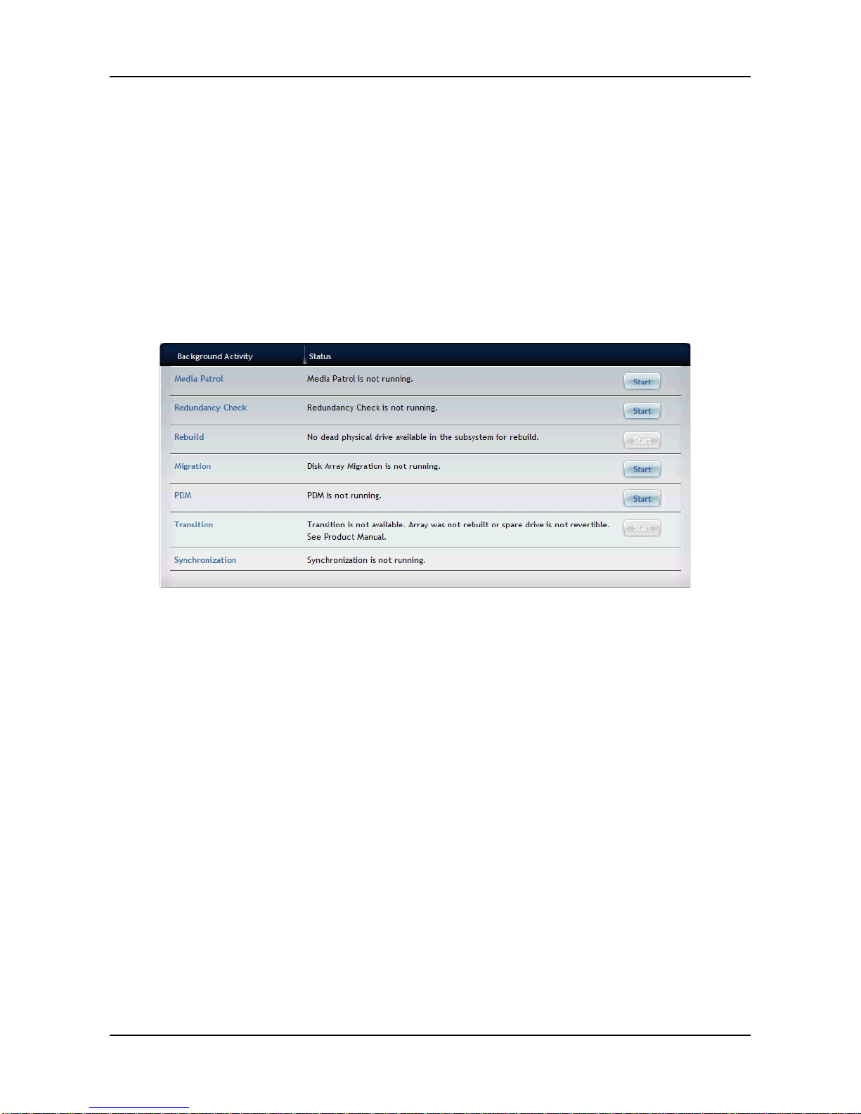
To view current background activity, click AdminTool tab > Background
Activity.
The list of Background Activities displays information, including:
− Media Patrol:
Media Patrol is a routine maintenance Procedure that
checks the magnetic media on each disk drive. Media
Patrol checks all physical drives assigned to disk arrays
and spare drives. Media Patrol does not check
un-configured drives.
Media Patrol checks are enabled by default on all disk
arrays and spare drives. You can disable Media Patrol in
the disk array and spare drive settings, however that action
is not recommended.
Unlike Synchronization and Redundancy Check, Media
Patrol is concerned with the condition of the media itself,
not the data recorded on the media. If Media Patrol
encounters a critical error, it triggers PDM if PDM is
enabled on the disk array.
Media Patrol has three status conditions:
Page 55

55
Running – Normal. You can access your logical drives at
any time.
Yield – Temporary pause while a read/write operation takes
place.
Paused– Temporary pause while another background runs.
Or a pause initiated by the user.
− Redundancy Check:
Redundancy Check is a routine maintenance Procedure for
fault-tolerant disk arrays (those with redundancy) that
ensures all the data matches exactly. Redundancy Check
can also correct inconsistencies.
− Rebuild:
When you rebuild a disk array, you are actually rebuilding
the data on one physical drive.
When a physical drive in a disk array fails and a spare drive
of adequate capacity is available, the disk array begins to
rebuild automatically using the spare drive.
If there is no spare drive of adequate capacity, but the Auto
Rebuild function is ENABLED, the disk array begins to
rebuild automatically as soon as you remove the failed
physical drive and install an un-configured physical drive in
the same slot.
If there is no spare drive of adequate capacity and the Auto
Rebuild function is DISABLED, you must replace the failed
drive with an un-configured physical drive, then perform a
Manual Rebuild. See below.
IMPORTANT: IF YOUR REPLACEMENT DISK DRIVE WAS FORMERLY
PART OF A DIFFERENT DISK ARRA Y OR LOGICAL DRIVE, YOU MUST
CLEAR THE CONFIGURATION DATA ON THE REPLACEMENT DRIVE
BEFORE YOU USE IT.
Page 56

ShareCenter Pro User Manual
56
− Migration:
The term "Migration" means either or both of the following
Change the RAID level of a logical drive
Expand the storage capacity of a logical drive
Befor e you begin a m igr atio n, examine your current disk
array to determine whether:
The physical drives in your array can support the target
RAID level
There is sufficient capacity to accommodate the target
logical drive size
If you need to add capacity to the array, be sure there are
unassigned physical drives installed in you RAID system
before you begin the migration.
Supported RAID level
Target
Source
RAID0 RAID1 RAID5 RAID6 RAID10
RAID0
● ● ● ● ●
RAID1
●
●
●
RAID5
●
● ● ●
RAID6
●
RAID10
●
● ● ●
− PDM:
Predictive Data Migration (PDM) is the migration of data
from the suspect disk drive to a spare disk drive, similar to
rebuilding a logical drive. B ut unlik e Rebuilding, PDM
constantly monitors your disk drives and automatically
copies your data to a spare disk drive BEFORE the disk
drive fails and your logical drive goes Critical.
The following actions trigger PDM:
A disk drive with unhealthy status (see below)
Media Patrol finds a disk critical error
You initiate PDM manually
Page 57

57
PDM also counts the number of media errors reported by
Media Patrol.
A disk drive becomes unhealthy when:
A SMART error is reported
The bad sector remapping table fills to the specified
level.
Y ou can specify the maximum levels for the reassigned and
error blocks in PDM settings. When the table fills to a
specified value, PDM triggers a migration of data from the
suspect drive (the disk drive with the bad sectors) to a
replacement physical drive.
During data migration, you will have access to your logical
drives but they will respond more slowly to read/write tasks
because of the additional operation. The time required for
data migration depends on the size of the disk drives.
PDM is enabled on all disk arrays by default. You can
disable PDM in the disk array settings, however that action
is not recommended.
− Transition:
Transition is the Process of replacing a revertible spare
drive that is currently part of a disk array with an
un-configured physical drive or a non-revertible spare. The
revertible spare drive returns to its original status. In order
to run the Transition function, the spare drive must be
revertible.
In addition, you must specify an un-conf i gur ed physical
drive of the same or larger capacity and same media type
as the revertible spare drive.
− Synchronization:
Synchronization is automatically applied to logical drives
when they are created. Synchronization recalculates the
redundancy data to ensure that the working data on the
physical drives is Proper ly in s ync.
Mouse-o ver on the log ical driv e, click the View button, and
Page 58
ShareCenter Pro User Manual
58
look under Logical Drive Information beside the line that
says Synchronized. A Yes means the logical drive was
synchronized.
Select the item you want (e.g. Media Patrol, PDM, Rebuild, etc.) from the list
and click the Start button to run the background activity.
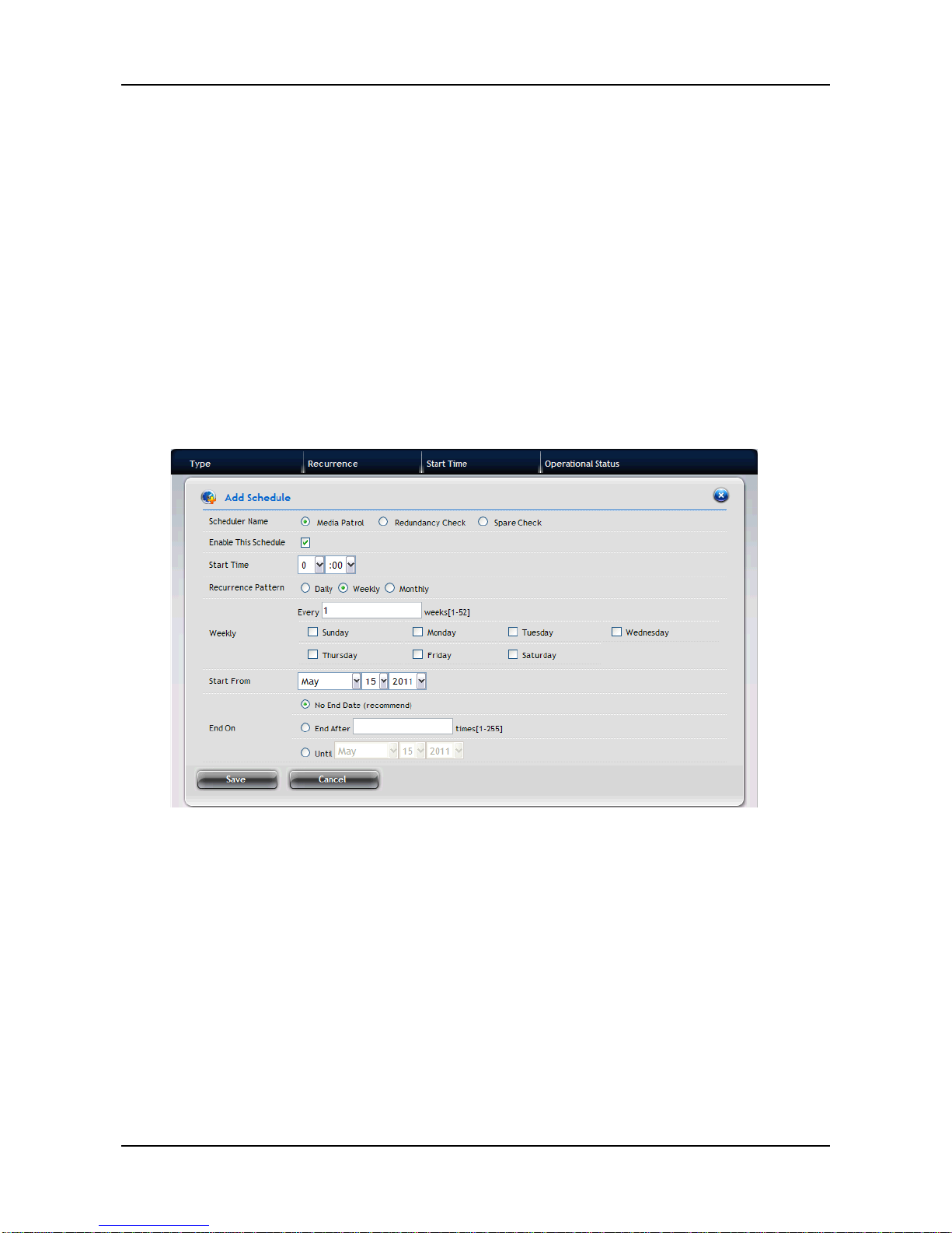
To add a scheduled background activity:
1. Click AdminTool tab > Background Ac tivity.
2. Click the Scheduler button.
3. Click the Add Schedule button and complete the required settings:
− Scheduler Name – Selec t Med ia Patro l, Batt ery Recondition,
Power On, Redundancy Check, Spare Check, or Power Off.
If you select Redundancy Check, the following settings need
to be completed:
Auto Fix – Attempts to repair the Problem when it finds an
error.
Pause on Err or – The Process stops when it finds a
non-repairable error.
Select LD – Select at least one log ical drive on whic h
Redundancy Check will run.
− Enable This Schedule – Select to enable this function.
Page 59
59
− Start Time – Choose a start time.
− Recurrence Pattern – Select a Recurrence Pattern as Daily,
Weekly, or Monthly.
− Start From – Select a start date.
− End On – Select an end option.
4. When done, click the Save button.
To view scheduled background activity:
1. Click AdminTool tab > Background Acti vity.
2. Click the Scheduler button. The list of Scheduled Background Activities
displays, including :
− Type – Media Patrol, Redundancy Check, or Spare Check.
− Recurrence – Daily, weekly, monthly.
− Start Time – Date and time.
− Operati ona l Stat us – Enabled or disabled.
To change a scheduled background activity:
1. Click AdminTool tab > Background Ac tivity.
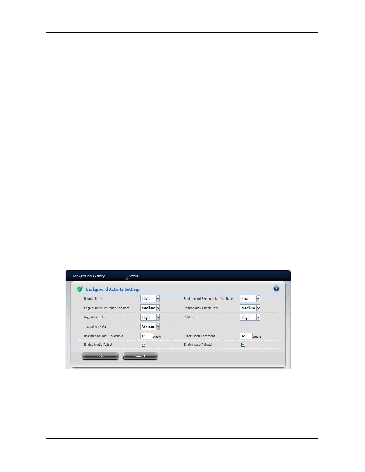
2. Click the Settings button. In the Background Activity Settings, you can
change the following settings for the background activity:
− Rebuild Rate
− Background Synchronization Rate
− Logical Drive Initialization Rate
− Redundancy Check Rate
− Migration Rate
Page 60
ShareCenter Pro User Manual
60
− PDM Rate
− Transition Rate
− Reassigned Block Threshold
− Error Block Threshold
− Enable Media Patrol
− Enable Auto Rebuild
For example, to change the Rebuild settings:
1. Click the Rebuild Rate dropdown menu and choose a rate:
− Low – Fewer system resources to the Rebuild, more to data
read/write operations.
− Medium – Balances system resources between the Rebuild
and data read/write operations.
− High – More system resources to the Rebuild, fewer to data
read/write operations.
2. Check the Enable Auto Rebuild box to enable Auto Rebuild (rebuilds
when you swap out the failed drive with a new one).
3. Click the Confirm button.
3.5.5 Firmware updates
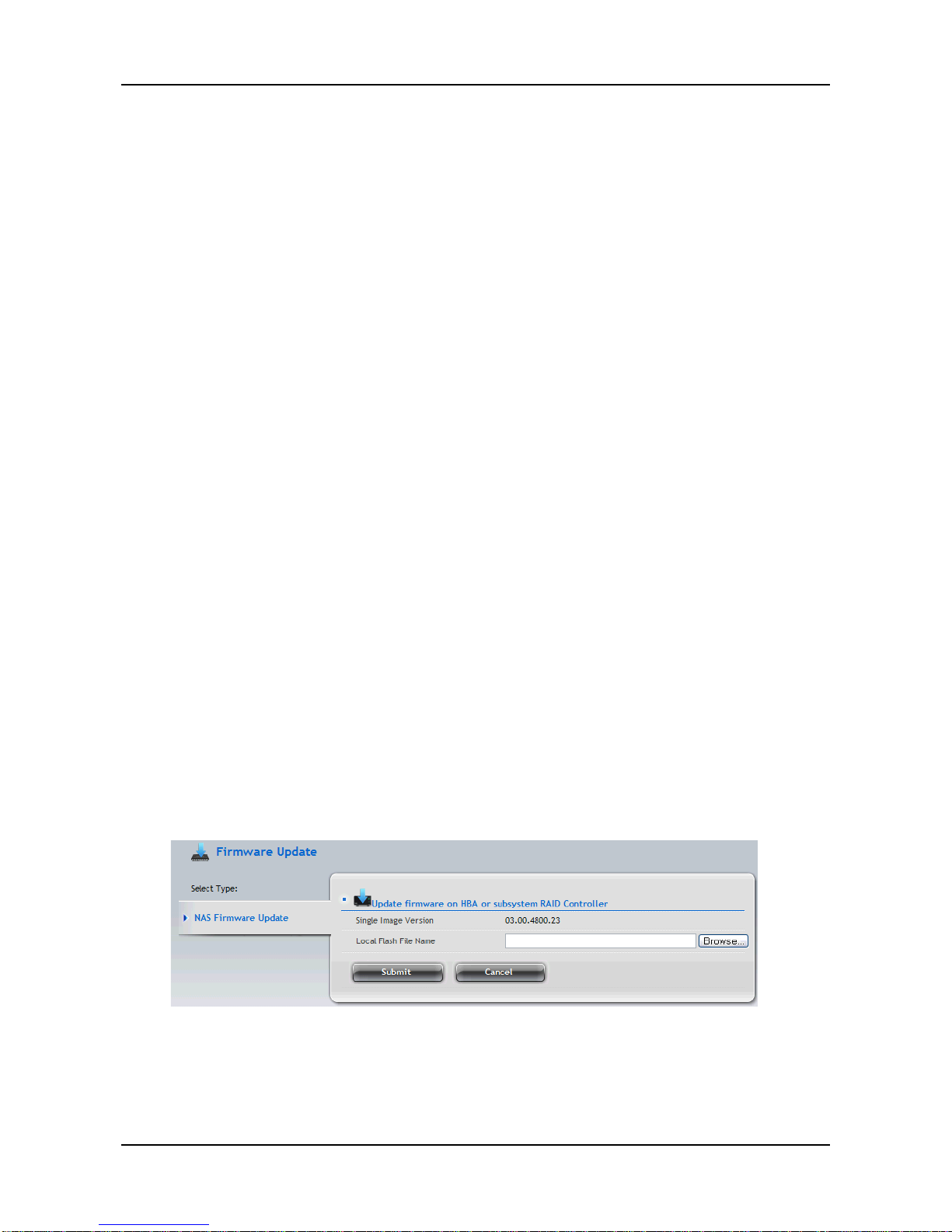
Before you update the firmware, download the latest firmware image file to
your PC/Mac
1. Click AdminTool tab > Firmware Update. The NAS Firmware Update
window screen appears showing the current Image Version Number.
2. Click the Browse button to locate the firmware image file, and then click
the Open button.
Page 61
61
3. The firmware image file appears in the in the field.
4. Click the Submit button.
5. When the update is completed a message tells you to reboot the
subsystem. Click the OK button to restart the system.
Warning: Do NOT power off the system during the update!
3.5.6 Performance monitor
The Performance Monitor screen allows you to monitor the performance of
NAS using the analyzed illustrations.
Support T able:
Logical Drive Physical Drive Port
Bandwidth
● ● ●
Cache Usage
●
Dirty Cache
●
Maximum Latency
● ● ●
Average Latency
● ● ●
Minimum Latency
● ● ●
IO request
● ● ●
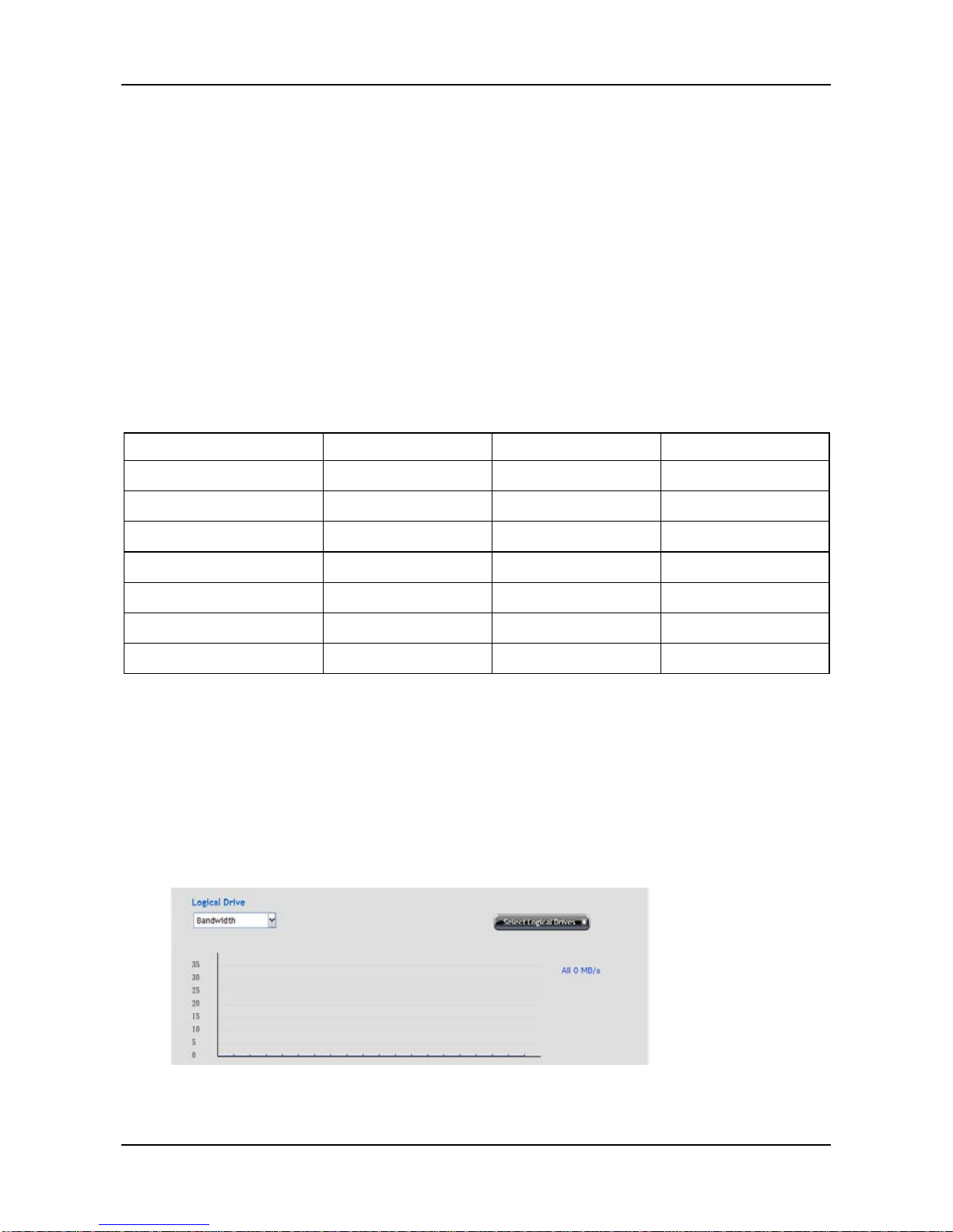
To view the Logical Drive performance:
1. Click AdminTool tab > Performance Monitor.
2. In the Logical Drive field, click the Select Logical Drives button to select
the logical drive you want and select a performance type from the
dropdown menu. When done, the performance of selected logical drive
will be shown in the illustration below.
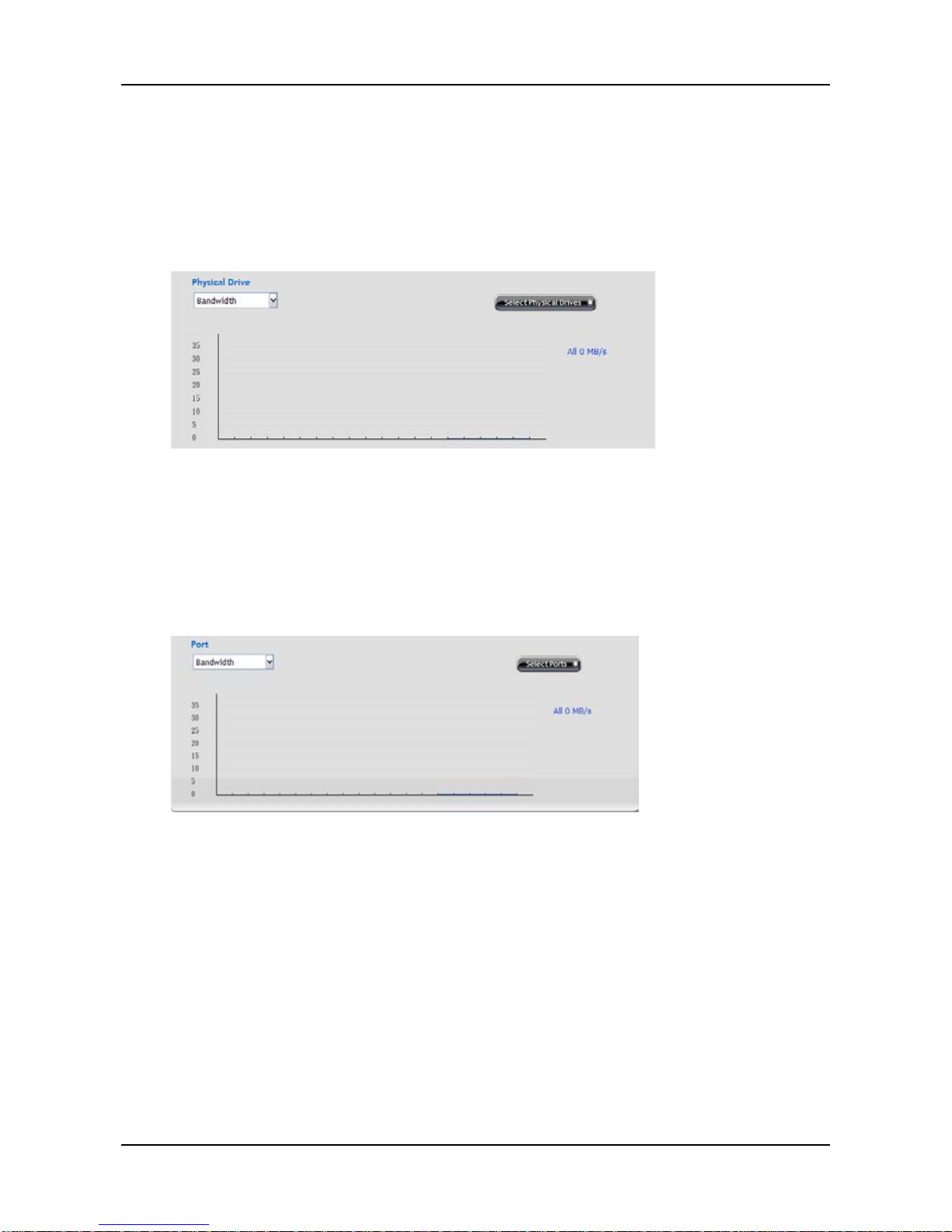
To view the Physical Dr i ve perf ormance:
Page 62
ShareCenter Pro User Manual
62
1. Click AdminTool tab > Performance Monitor.
2. In the Physical Drive field, click the Select Physical Drives button to
select the physical drive you want and select a performance type from
the dropdown menu. When done, the performance of selected physical
drive will be shown in the illustration below.
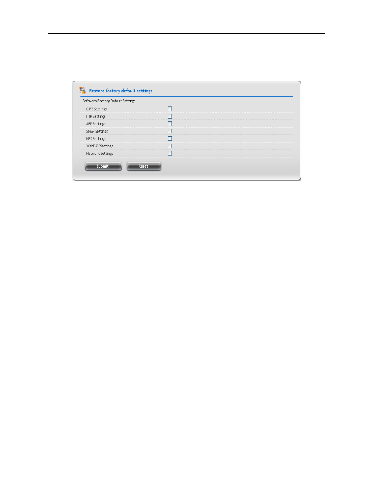
To view the Port performance:
1. Click AdminTool tab > Performance Monitor.
2. In the Port field, click the Select Ports button to select the port you want
and select a performance type from the dropdown menu. When done,
the performance of selected port will be shown in the illustration below.
Page 63
63
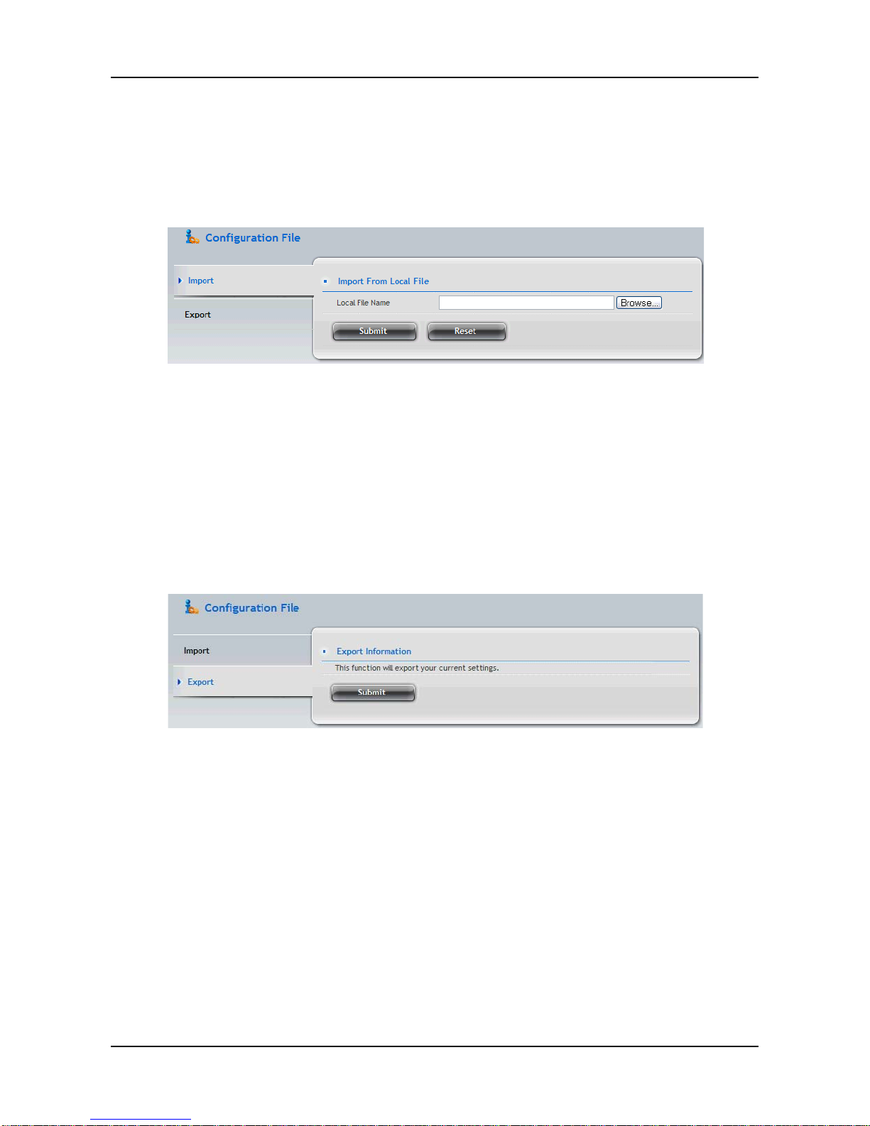
3.5.7 Restore factory default settings
The Restore Factory Default function allows you to restores settings (any or
all) to their default values for the NAS.
The settings include:
− CIFS Settings
− FTP Settings
− AFP Settings
− SNM P Setti ngs
− NFS Settings
− WebDAV Settings
− Network Settings
Caution: Use this feature only when required and only on the settings
that you must reset to default in order to set them correctly.
To restore the factory default settings:
1. Click AdminTool tab > Restore Factory Defa u lt.
2. In the Restore factory default settings screen, check the boxes beside
the settings you want to reset to default value.
3. Click the Submit button.
4. Click the OK button in the confirmation box.
Page 64
ShareCenter Pro User Manual
64
3.5.8 Import/Export a system configuration file
To import the configuration file to the NAS:
1. Click AdminTool tab > Configuration File.
2. Click the Import button.
3. Click the Browse button to locate the configuration file (.bcf), and then
click the Open button.
4. Click the summit button
5. The NAS system will reboot
To export the current configuration file:
1. Click AdminTool tab > Configuration File.
2. Click the Export button.
3. Click the Submit button. The current configuration will be saved as
a .bcf file in your Host PC.
Page 65
65
3.5.9 LUNMap Management
The LUN Mapping function allows you to control what storage arrays are
visible to which computers.
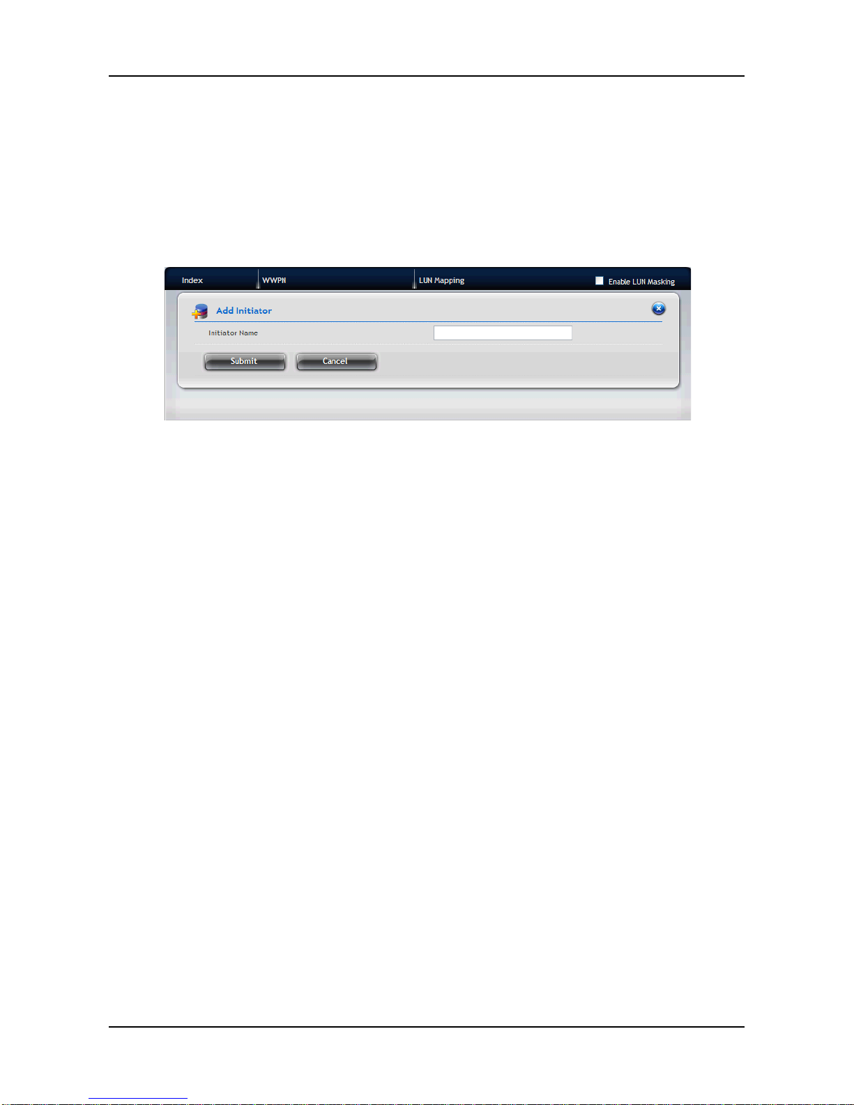
To add initiator:
1. Click AdminTool tab > LUNMap.
2. Click the Add Initiator button.
3. Enter a name in the Initiator Name field and click the Submit button. The
initiator will be added in the LUNMap list.
To define the LUN Mapping
1. Click AdminTool tab > LUNMap.
2. Click the LUN Mapping button.
3. Select the initiator you want from the dropdown menu and click the Next
button.
4. In the LUN Mapping field, indicate the arrays you wish to make visible by
putting a unique number in the LUN field.
5. When done, click the Assign button.
6. Click the Submit button.
7. Check the Enable LUN Masking option to enable the LUN Mapping and
Masking function of the NAS.
Page 66
ShareCenter Pro User Manual
66
3.5.10 Power Option
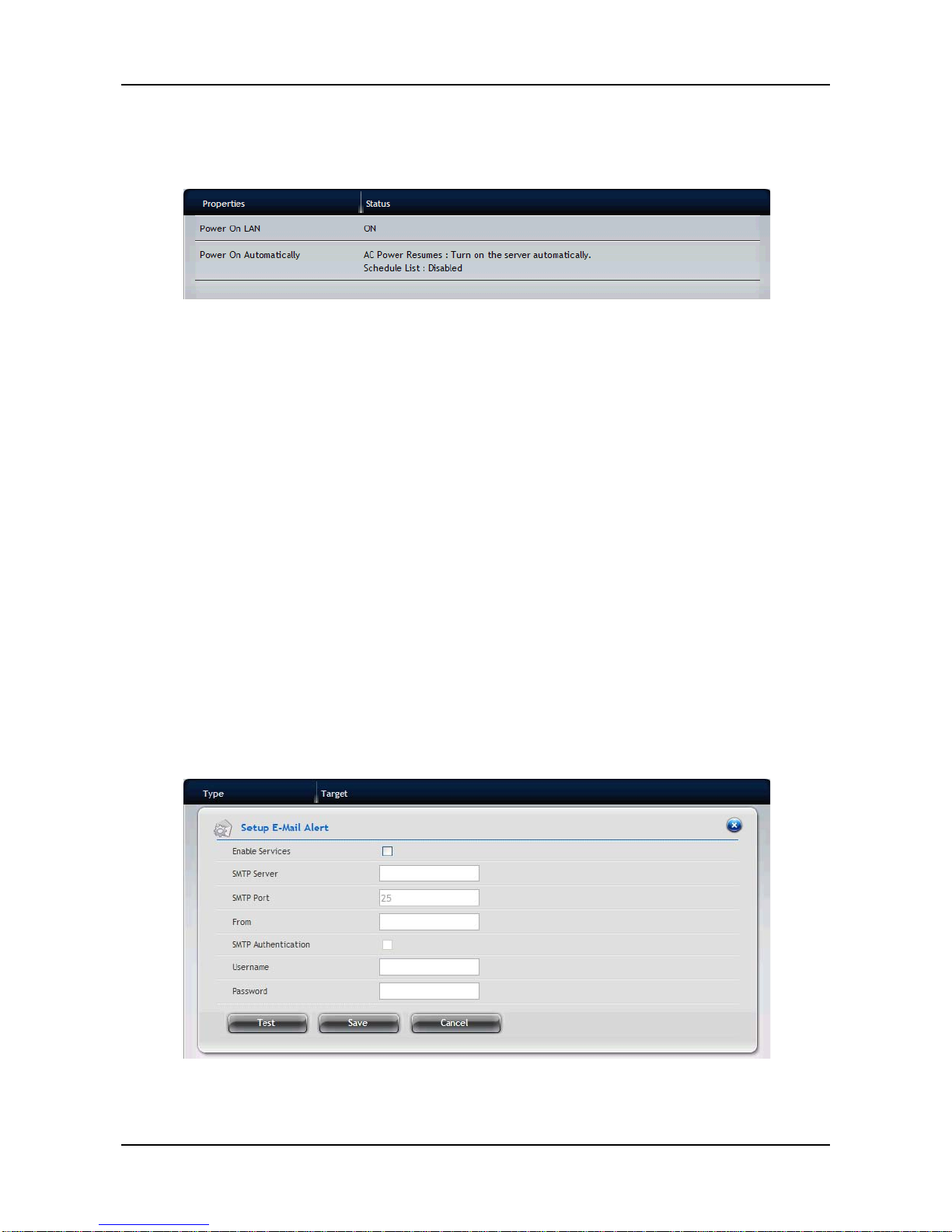
The Power Option screen displays the power management of the NAS.
You can change the following power settings from the screen by moving the
mouse over the setting item and clicking the Settings button:
− Power On LAN
When system shutdown, accept magic packet to power
ON.
ShareCenter
®
NAVI can be the utility to power on NAS by
LAN.
− Power On Automatically
3.5.11 M essage Alert
The Message Alert function allows the user to receive an e-mail alert for the
events of the NAS.
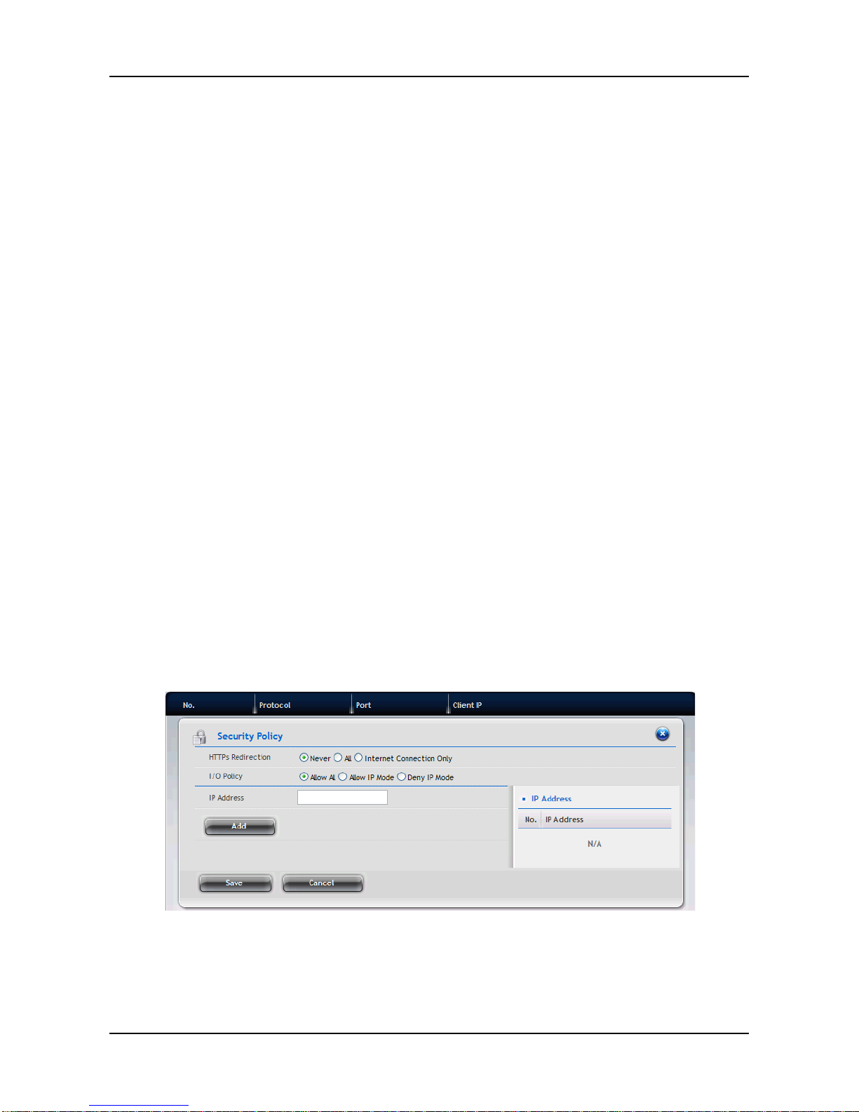
To set up the e-mail service for the NAS:
1. Click AdminTool tab > Message Alert.
2. Click the Setup button to setup the mail server complete the required
settings in the Setup E-Mail Alert field.
− Enable Services – Check to enable message alert service.
− SMT P Server – Enter the IP address of SMTP server.
Page 67
67
− SMT P Port – Enter the port number of SMTP server
− From – The sender of the notification message.
− SMTP Authen ticati on
− Username – Enter the username to log in the SMTP server.
− Password – Enter the password to log in the SMTP server.
To set up the e-mail account:
1. Click AdminTool tab > Message Alert.
2. Click the Create button.
3. Enter your e-mail address and click the Save button.
To edit the e-mail account:
1. Click AdminTool tab > Message Alert.
2. Move your mouse over the e-mail account in the list, and you can:
− Change the address of the account by clicking the Settings
button.
− Remove the selected account by clicking the Delete button.
3.5.12 Network Security
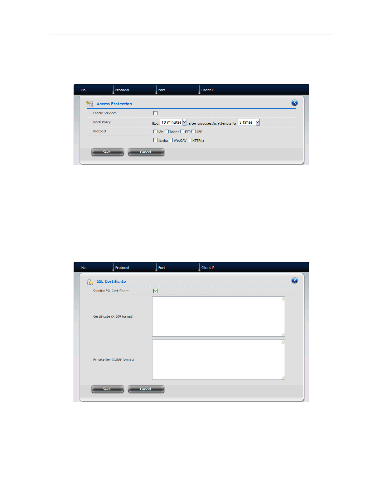
To set up Security Policy:
1. Click AdminTool tab > Network Securiey.
2. Click the Security Policy button and complete the required settings.
− HTTPs Redirection
− I/O Policy
− IP/Domain Name
3. When done, click the Save button.
Page 68

ShareCenter Pro User Manual
68
Page 69
69
To set up Access Protection:
1. Click AdminTool tab > Network Security.
2. Click the Access Protection button and complete the required settings.
− Enable Services – Check to enable the function.
− Block Policy
− Protocol
3. When done, click the Save button.
To set up SSL Certificate:
1. Click AdminTool tab > Network Security.
2. Click the S SL Certifi cate button and complete the required settings.
− Specific SSL Certificate – Check to enable the function.
− Certificate (X.509 format)
− Private Key (X.509 format)
3. When done, click the Save button.
Page 70
ShareCenter Pro User Manual
70
3.6 NAS Tab
3.6.1 Setup Wizard
The system’s Wizard lets you configure your disk array(s) easily and quickly.
The Wizard will guide you through the required settings step by step. You can
choose to configure automatically by using One-Click Setup, or configure
manually by using Advance Setup.
Using Automatic Configuration Wizard
1. Click NAS tab > Wizard.
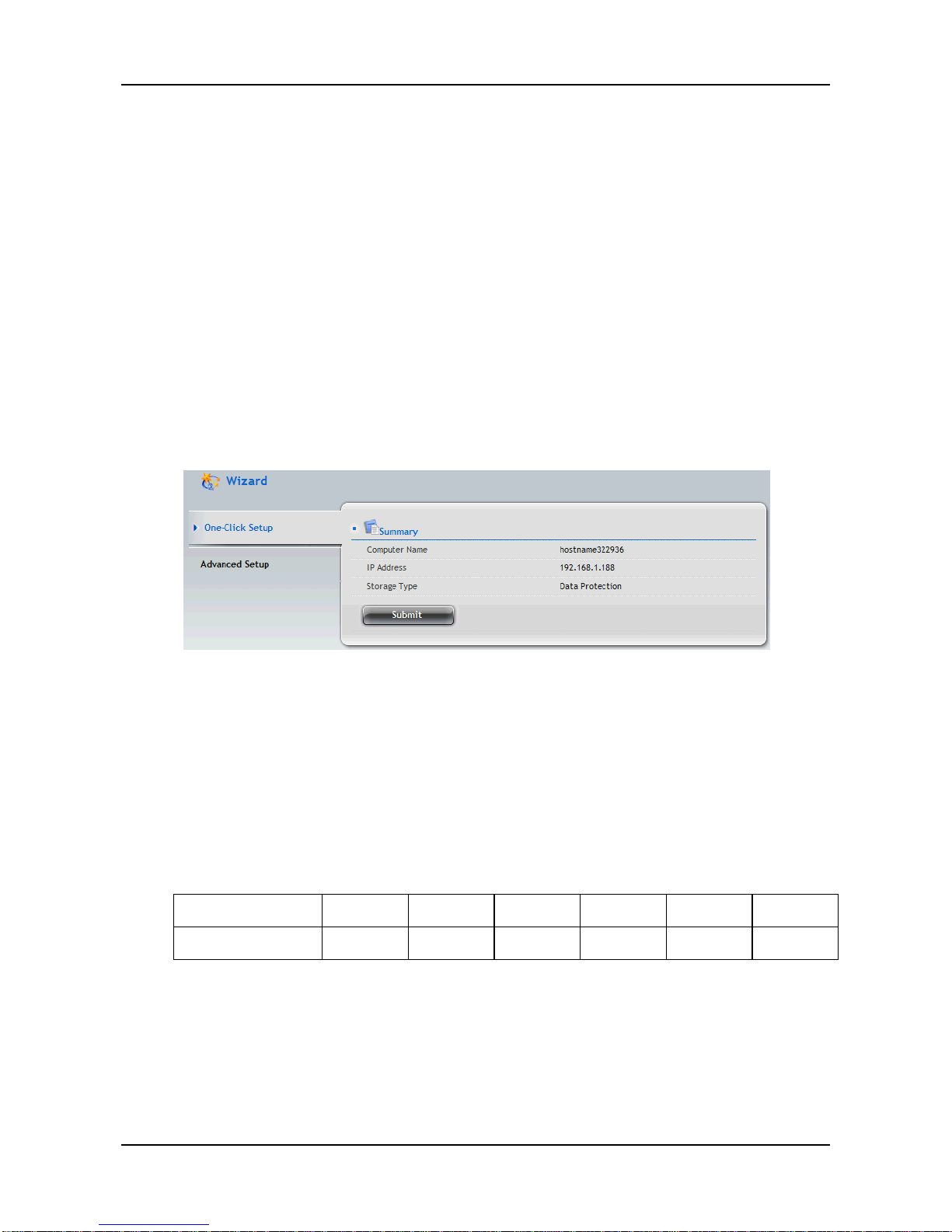
2. Click the One-Click Setup button. The Automatic Configuration box
displays:
3. The Summary window displays the general information of the system,
including:
− Computer Name
− IP Address
− Storage Type
4. To accept the Proposed configuration, click the Submit button.
Note: The system will create the RAID automatically based on the number of the disk
Disk number 1 2 3 4 5 6
RAID type RAID0 RAID1 RAID5 RAID5 RAID5 RAID6
If you disagree with the Proposed configuration, click the Advance Setup
button to directly specify all parameters for a new disk array, logical drives,
and spare drives.
Page 71
71
Using Advanced Configuration Wizard
1. Click NAS tab > Wizard.
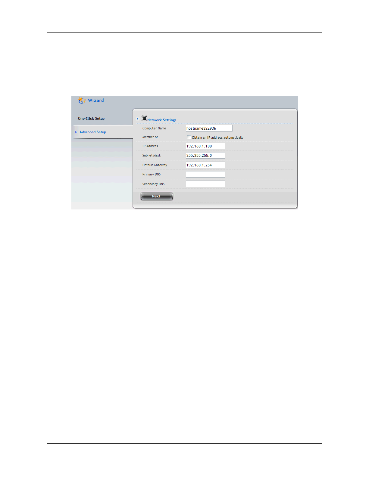
2. Click the Advance Setup button. The Advanced Configuration box
displays:
3. Complete the required settings in the Network Settings window,
including:
− Computer Name
− Obtain an IP address automatically
− IP Address
− Subnet Mas k
− Default Gateway
− Primary DNS
− Secon dar y DN S
When done, click the Next button.
4. Select Storage Type: Data Protection or Maximum Capacity, and then
click the Next button.
5. The Summary window displays the general information of the system,
including:
− Computer Name
− IP Address
− Storage Type
To accept the Proposed configuration, click the Submit button.
Page 72
ShareCenter Pro User Manual
72
3.6.2 User account management
To add users for the NAS:
1. Click NAS tab > NAS User.
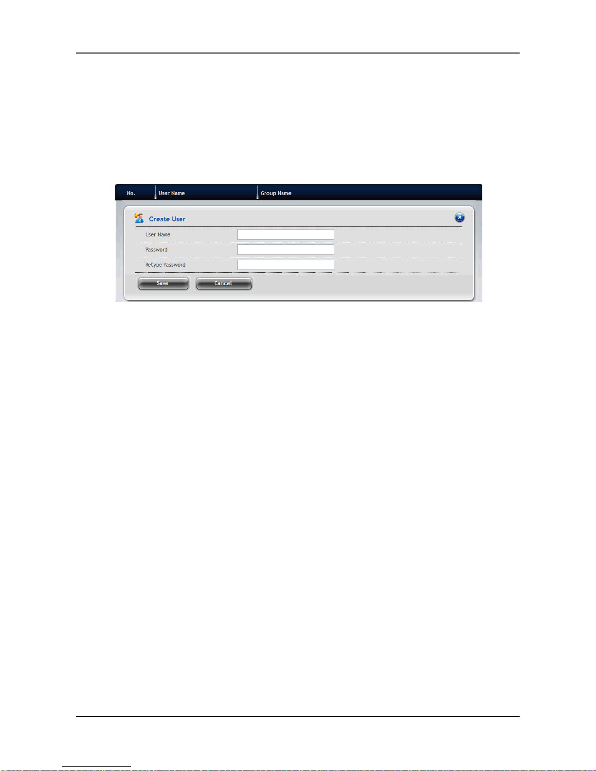
2. Click the Create User button.
3. In the Create User window, complete the required settings.
− User Name
− Password
− Ret ype Password
4. When done, click the Save button.
To view/edit the user information:
1. Click NAS tab > NAS User. The list of users displays.
2. Move your mouse over the user in the list, and you can:
− Change the password for the user to log in the NAS by clicking
the Change Password button.
− Remove the selected user by clicking the Delete button.
To group the users:
1. Click NAS tab > NAS User.
2. Click the Group button.
3. Click the Create Group button to add a group for the system:
a. Enter the Group Name, and click the Next button.
b. Select the user(s) you want to add to the group from the NAS
User field.
c. When done, click the Submit button.
Page 73
73
4. In the NAS Group list, move your mouse over the group item and then
you can:
− Add/remove the users for the group by clicking the Group
Settings button.
− Remove the selected group by clicking the Delete button.
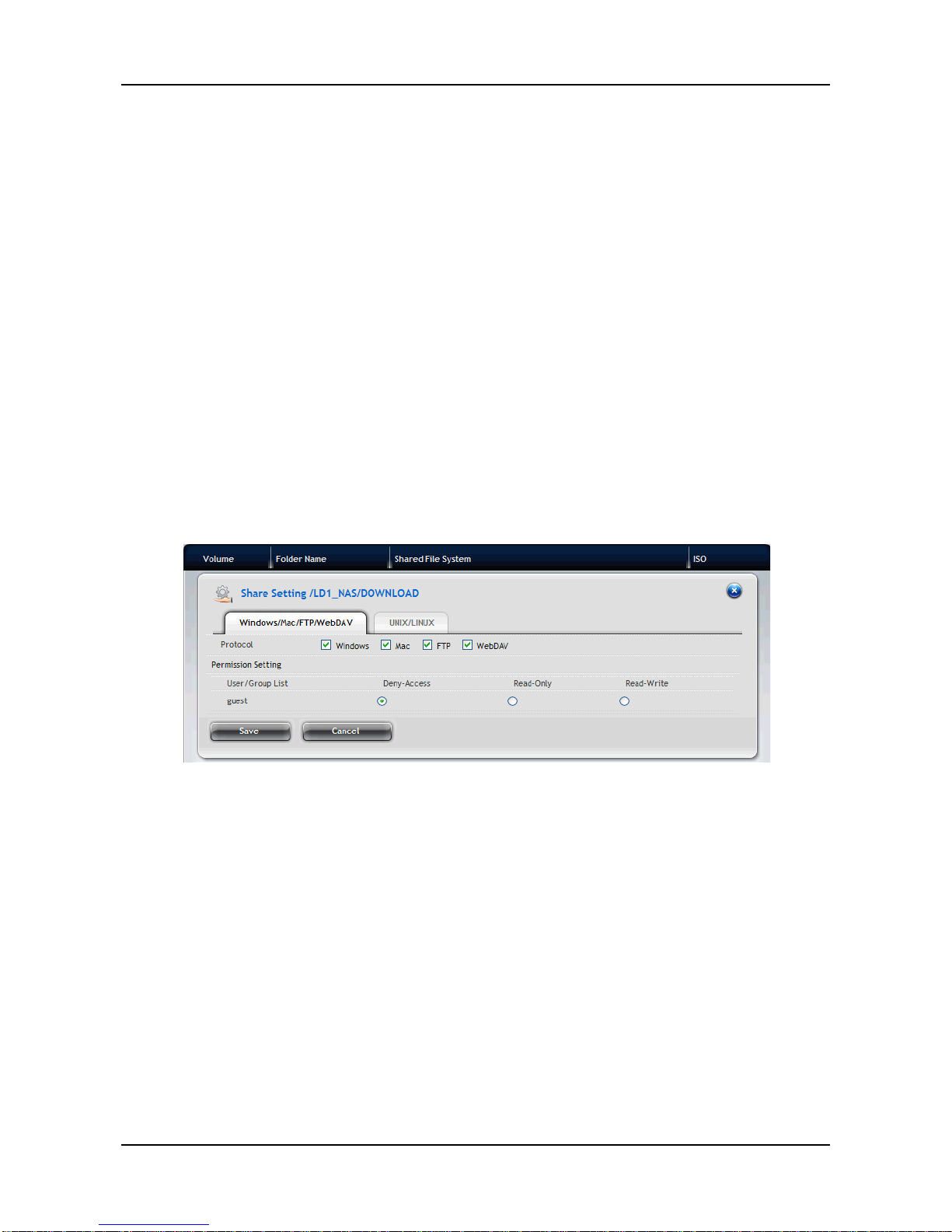
When the new user/group is added, you have to complete the permission
settings for each user/group to access the system. Follow the steps below to
complete the settings:
1. Click NAS tab > File Sharing.
2. From the File Sharing list, move your mouse over the folder you want
and click the Share Settings button.
3. Select the user/group you want and set one of the access options:
Deny-Access, Read-Only, or Read-Write
4. When done, click the Save button.
Page 74
ShareCenter Pro User Manual
74
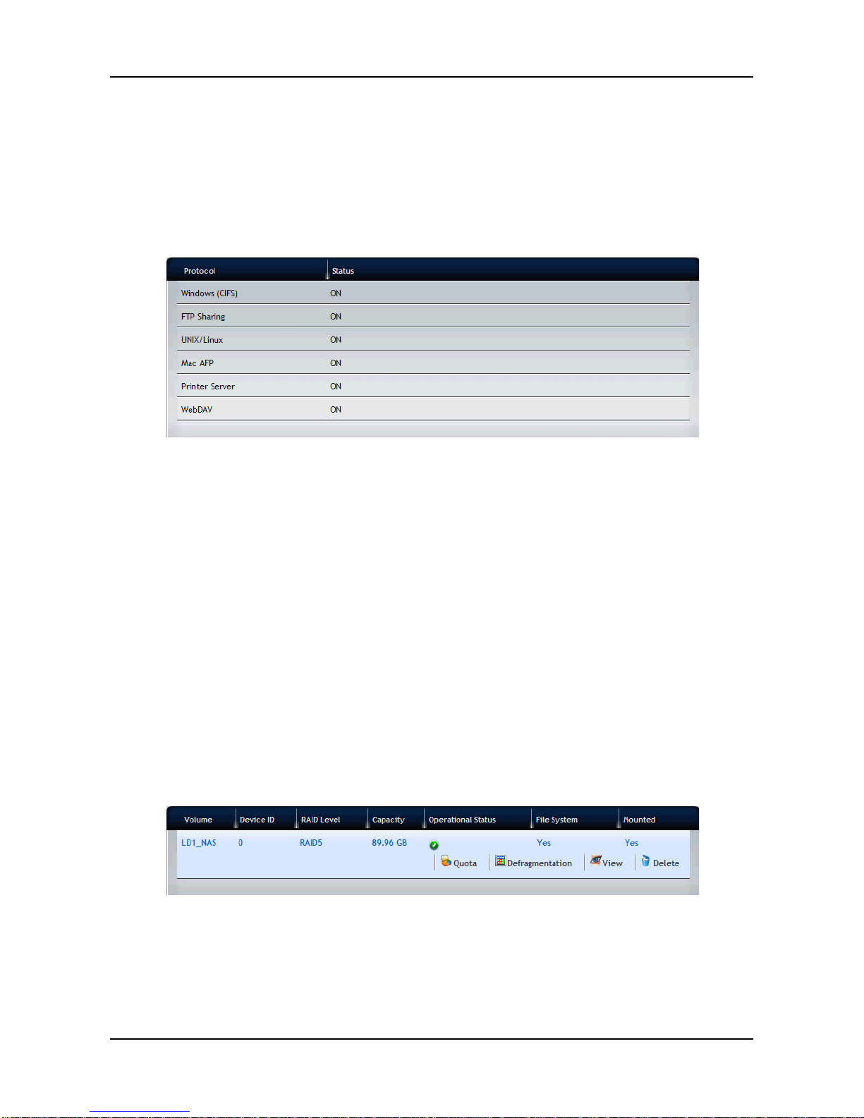
3.6.3 Protocol Control and Setting
1. Click NAS tab > Protocol Control.
2. In the Protocol Control list, move your mouse over the Protocol option
you want and click the Enable/Disable button to turn the feature
ON/OFF. The Protocols include:
− Windows (CIFS)
− FTP Sharing
− UNIX/Linux
− Mac AFP
− Printer Server
− WebDAV
3. To change the Protocol settings, move your mouse over the Protocol
option and click the Settings button to configure the advanced settings.
3.6.4 File System Management
1. Click NAS tab > File System.
2. In the File System list, move your mouse over the item you want an d you
can:
− View the volume information by clicking the View button.
− Change the quota setting of the file system by clicking the
Quota button.
− Remove the selected item by clicking the Delete button.
Page 75
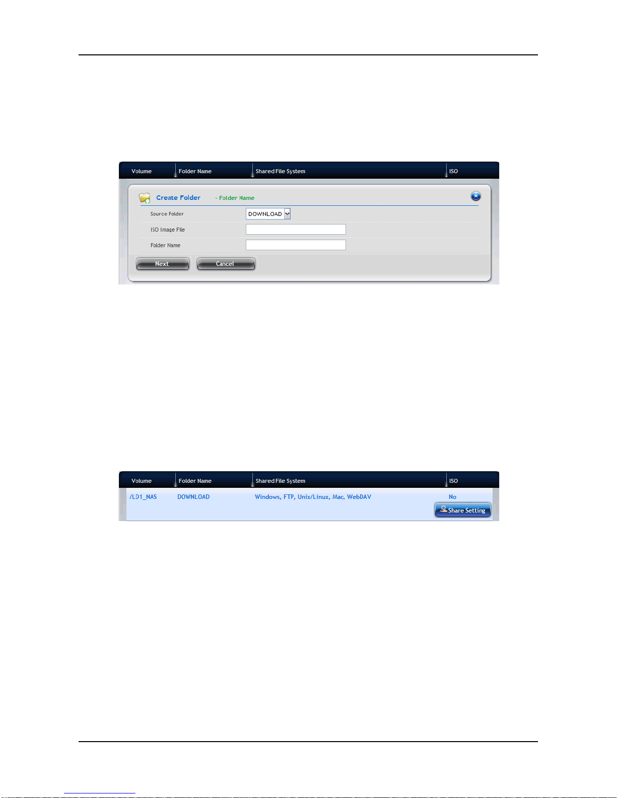
75
3.6.5 File Sharing Setting
Creating ISO Folder
1. Click NAS tab > File Sharing.
2. Click the Create ISO Folder button to add a folder for ISO file sharing:
a. Enter the Source Folder, ISO Image File and Folder Name, and
then click the Next button.
b. Select the Protocol as Windows/FTP or UNIX/LINUX, and then
click the Next button.
c. In the Permission Setting field, set the privilege for the users to
access the folder by selecting: Deny-Access, Read-Only, or
Read-Write. Click the Next button.
d. When done, click the Submit button.
3. In the File Sharing list, move your mouse over the item and clicking the
Share Setting button to change the sharing settings.
− Windows/Mac/FTP/WebDAV: Select the Protocol for your
networking configuration, and set up the Permission Setting
for each user/group.
− UNIX/LINUX: Assign the IP address in the New IP Address
box then click the Add button for sharing. Enter *.*.*.* if all IP
addresses are allowed for sharing.
When done, click the Save button.
Page 76
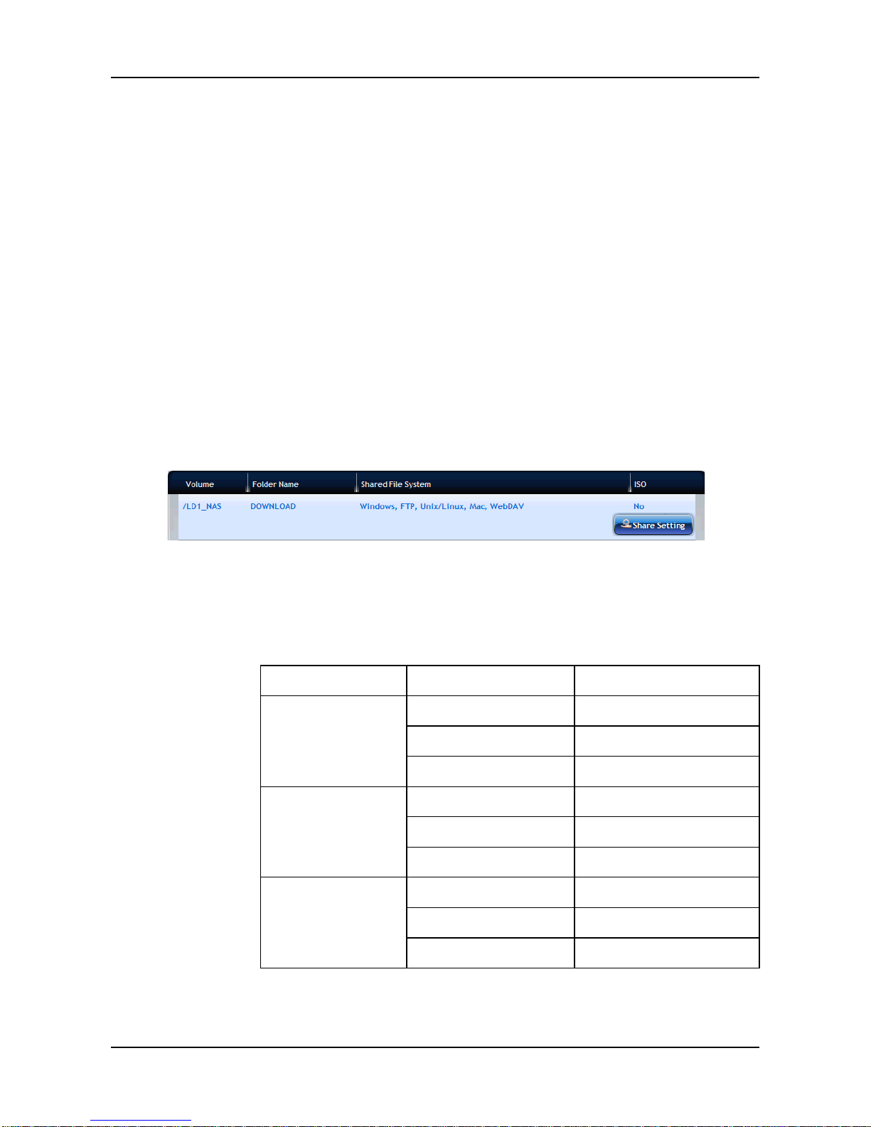
ShareCenter Pro User Manual
76
Creating Folder
1. Click NAS tab > File Sharing.
2. Click the Create Folder button to add a folder for sharing:
a. Enter the Volume and Folder Name, and then click the Next
button.
b. Select the Protocol as Windows/FTP or UNIX/LINUX, and then
click the Next button.
c. In the Permission Setting field, set the privilege for the users to
access the folder by selecting: Deny-Access, Read-Only, or
Read-Write. Click the Next button.
d. When done, click the Submit button.
3. In the File Sharing list, move your mouse over the item and clicking the
Share Setting button to change the sharing settings.
− Windows/Mac/FTP/WebDAV: Select the Protocol for your
networking configuration, and set up the Permission Setting
for each user/group.
• Windows (CIFS)
Group
Member
Result
Deny-Access
Deny-Access
Deny-Access
Read-Only
Deny-Access
Read-Write
Deny-Access
Read-Only
Deny-Access
Deny-Access
Read-Only
Read-Only
Read-Write
Read-Write
Read-Write
Deny-Access
Deny-Access
Read-Only
Read-Write
Read-Write
Read-Write
Page 77

77
• Mac AFP
Group
Member
Result
Deny-Access
Deny-Access
Deny-Access
Read-Only
Deny-Access
Read-Write
Deny-Access
Read-Only
Deny-Access
Deny-Access
Read-Only
Read-Only
Read-Write
Read-Only
Read-Write
Deny-Access
Deny-Access
Read-Only
Read-Only
Read-Write
Read-Write
• FTP
Group
Member
Result
Deny-Access
Deny-Access
Deny-Access
Read-Only
Deny-Access
Read-Write
Deny-Access
Read-Only
Deny-Access
Deny-Access
Read-Only
Read-Only
Read-Write
Read-Write
Read-Write
Deny-Access
Deny-Access
Read-Only
Read-Write
Read-Write
Read-Write
Page 78
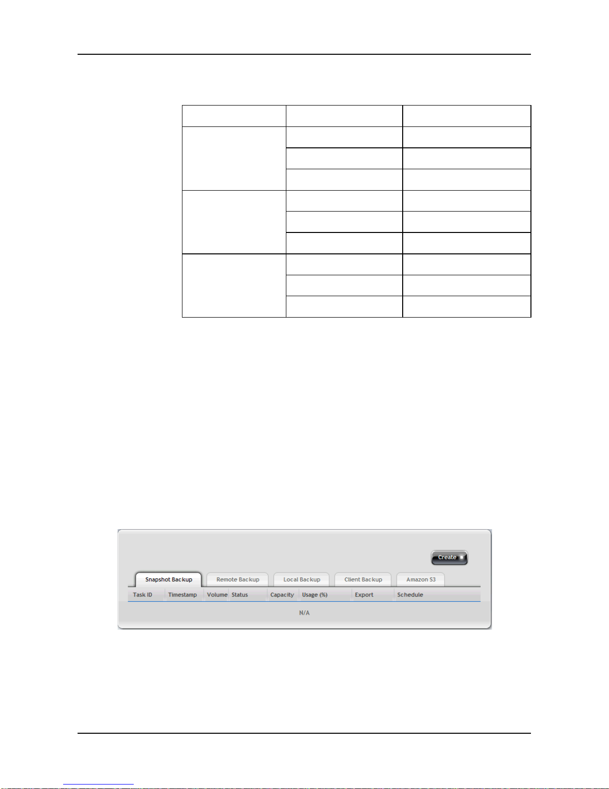
ShareCenter Pro User Manual
78
• WebDAV
Group
Member
Result
Deny-Access
Deny-Access
Deny-Access
Read-Only
Deny-Access
Read-Write
Deny-Access
Read-Only
Deny-Access
Deny-Access
Read-Only
Read-Only
Read-Write
Read-Only
Read-Write
Deny-Access
Deny-Access
Read-Only
Read-Only
Read-Write
Read-Write
− UNIX/LINUX: Assign the IP address in the New IP Address
box then click the Add button for sharing. Enter *.*.*.* if all IP
addresses are allowed for sharing.
When done, click the Save button.
3.6.6 Backup
1. Click NAS tab > Backup.
2. Select the Backup solution you want by clicking the tab: Snapshot
Backup, Remote Backup, Local Backup, Client Backup, and
Amazon S3.
Page 79
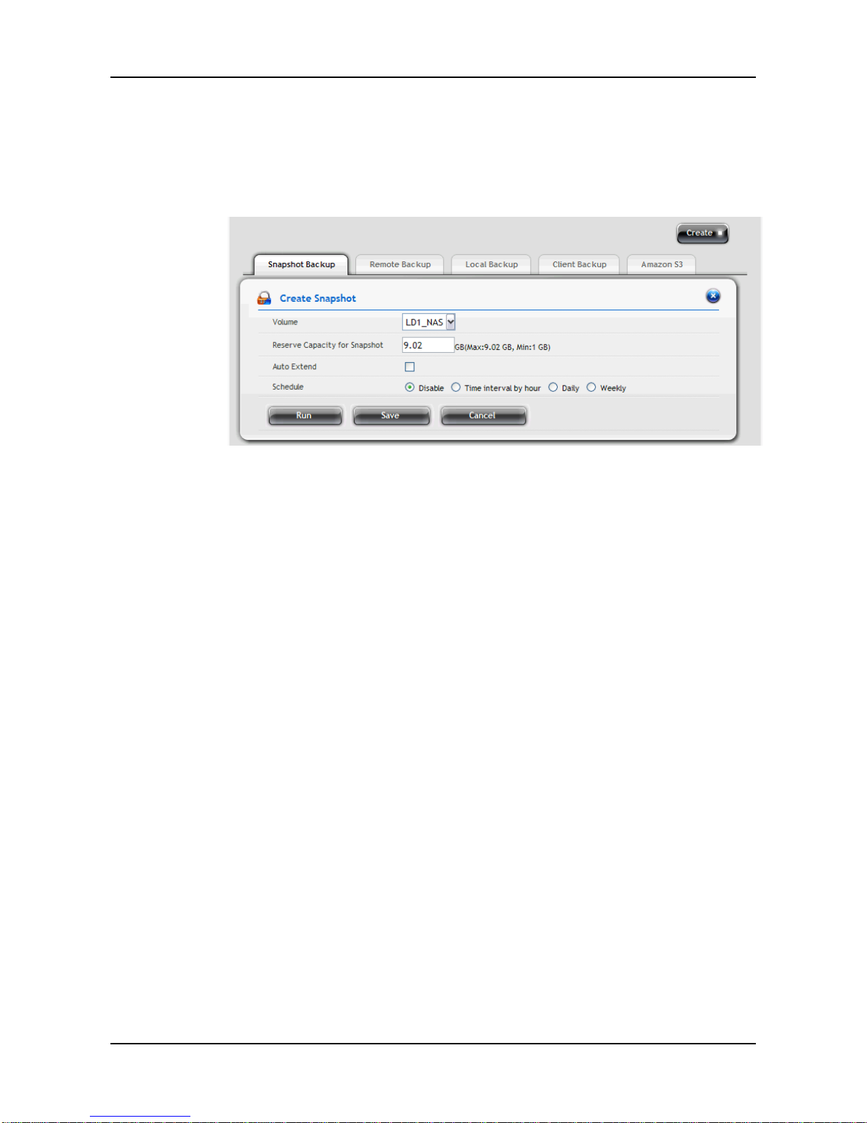
79
• Snapshot Backup
1. Click NAS tab > Backup > Snapshot Backup tab.
2. Click the Create button and complete the required settings in
the Create Snapshot windo w.
− Volume: Select the desired setting from the dropdown
menu.
− Reserve Capacity for Snapshot: From the dropdown
menu, assign the reserved capacity for the backup
solution.
− Auto Extend: Click to checkbox to enable or disable the
function.
− Schedule: Select one of the schedule types you want for
the backup solution.
Disable – no snapshots will be taken.
Time interval by hour – snapshots will be taken at the
hourly interval you choose from the dropdown menu.
Daily – snapshots will be taken at the time of day you
choose from the dropdown menus .
Weekly – snapshots will be taken on the day of the
week, at the time of day you choose from the
dropdown menus.
3. When done, click the Run button. The new backup schedule is
applied.
4. T o change the settings of the backup solution, move you mouse
over the item you want and click the option button.
Page 80
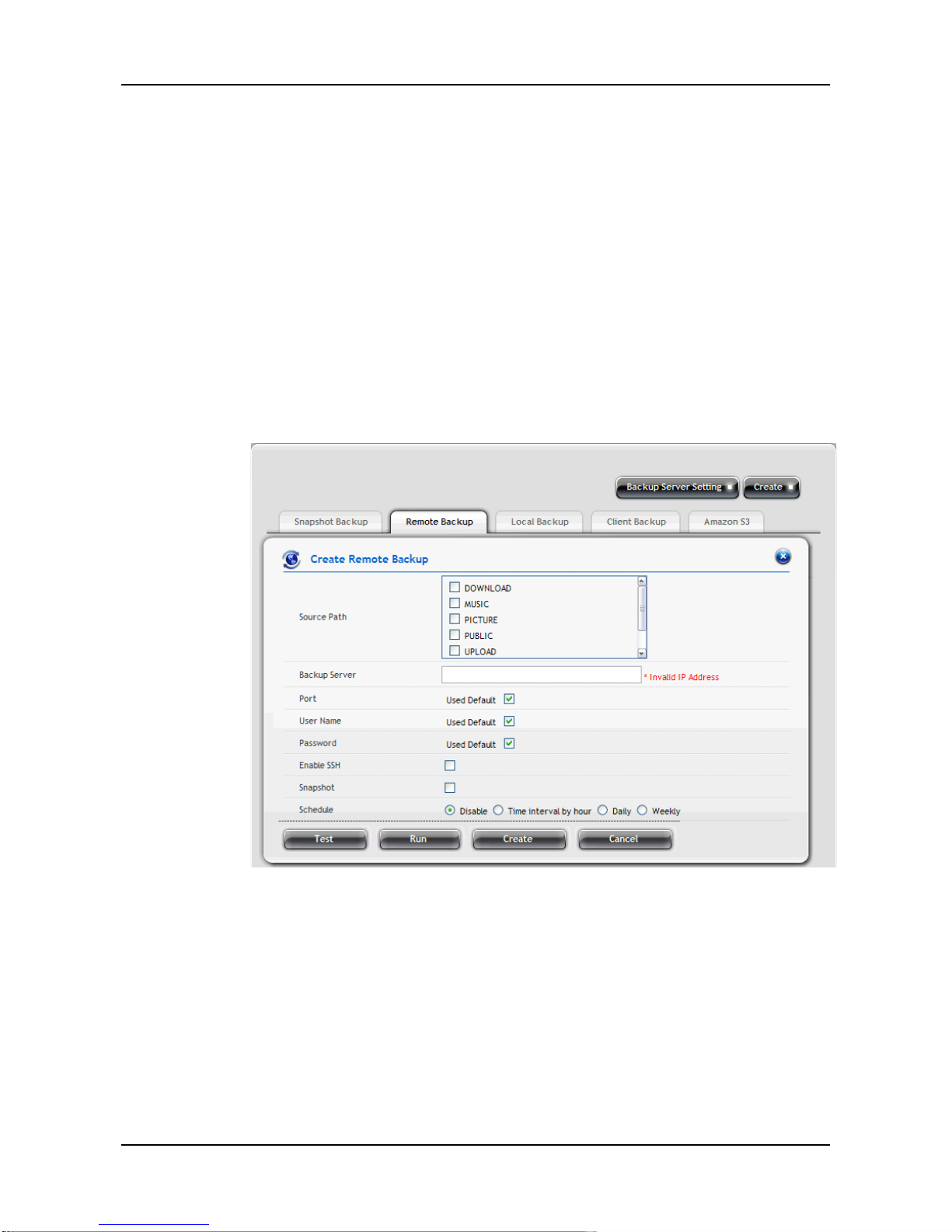
ShareCenter Pro User Manual
80
− Recovery: Click to restore the data volume using the
Snapshot.
− Export: Click to export the Snapshot to the share folder.
− Settings: Click to change the settings of the backup
solution.
− Delete: Click to delete the backup solution.
• Remote Backup
1. Click NAS tab > Backup > Remote Backup tab.
2. Click the Create button and complete the required settings in
the Create Remote Backup window.
− Source Path
− Backup Server: Enter the IP address of the remote backup
server.
− Port: Enter the port number for the remote backup server.
− User Name: Enter the user name to login the remote
backup server.
− Password: Enter the password to login the remote backup
server.
− Enable SSL: Select this option if the server requires SSL.
Page 81

81
− Snapshot: Select this option if you want to upload snapshot
of backup to the server.
− Schedule: Select one of the schedule types you want for
the backup solution.
Disable – no snapshots will be taken.
Time interval by hour – snapshots will be taken at the
hourly interval you choose from the dropdown menu.
Daily – snapshots will be taken at the time of day you
choose from the dropdown menus .
Weekly – snapshots will be taken on the day of the week,
at the time of day you choose from the dropdown menus.
3. When done, click the Run button. The new backup schedule is
applied.
You can click the Test button to test the server before applying
the settings.
4. T o change the settings of the backup solution, move you mouse
over the item you want and click the option button.
• Local Backup enables you to change the backup services of the
ShareCenter
®
Pro DNS-1550-04 and the USB storage device. To
set the Local Backup settings:
Notes:
The USB port on the front panel of the device supports Flash
drive, which ONL Y allows you to backup the data/file from the
Flash drive to the ShareCenter
®
Pro DNS-1550-04.
The four USB ports on the back panel ONLY allow you to
backup the data/file from the ShareCenter
®
Pro
DNS-1550-04 to the Flash drive.
Accessible
MBR partition (Maximum 2TB)
GPT partition
File system: FAT(32), NTFS, XFS, EXT3, HFS+
Format
MBR partition (Maximum 2TB)
Page 82
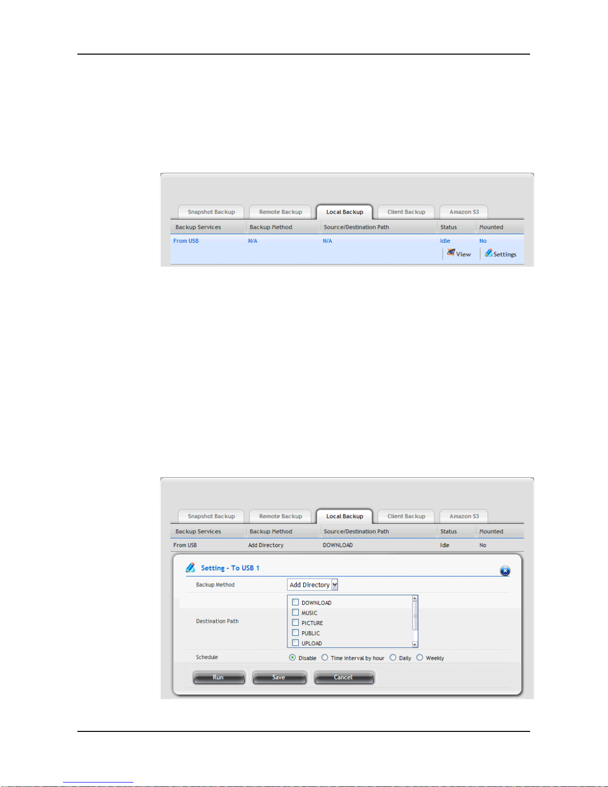
ShareCenter Pro User Manual
82
File system: FAT32, NTFS, XFS
1. Click NAS tab > Backup > Local Backup tab.
2. Move your mouse over the USB device you want and click the
Settings button.
3. Complete the required settings in the Setting window.
− Select the Enabl e Serv i ce s checkbox to enable the
backup solution.
− Select a Backup Method you want from the dropdown
menu: Add Directory, Copy, or Synchronize.
− Select a Folder Name you want from the list.
4. When done, you can:
− Click the Save button to apply the settings.
− Click the Run button to backup immediately.
− Set the backup schedule by selecting one of the schedule
types you want for the backup solution.
Page 83
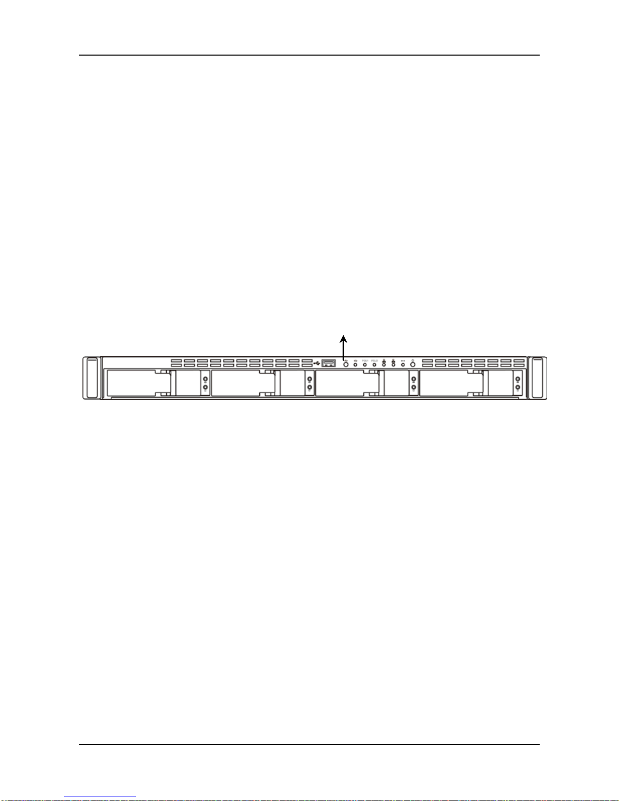
83
5. T o change the settings of the backup solution, move you mouse
over the item you want and click the Settings button.
• Client Backup allows you to enable One-Touch Backup function.
1. Click NAS tab > Backup > Client Backup tab.
2. Select the One Touch Backup checkbox to enable the backup
solution.
3. Click the Save button.
4. Now you can backup specified folders from your PC to the
ShareCenter
®
Pro DNS-1550-04 by simply pressing a button on
the front of the ShareCenter
®
Pro DNS-1550-04.
5. To disable One Touch Backup, uncheck One Touch Backup
and then click the Save button.
One-Touch
Backup
Button
Page 84
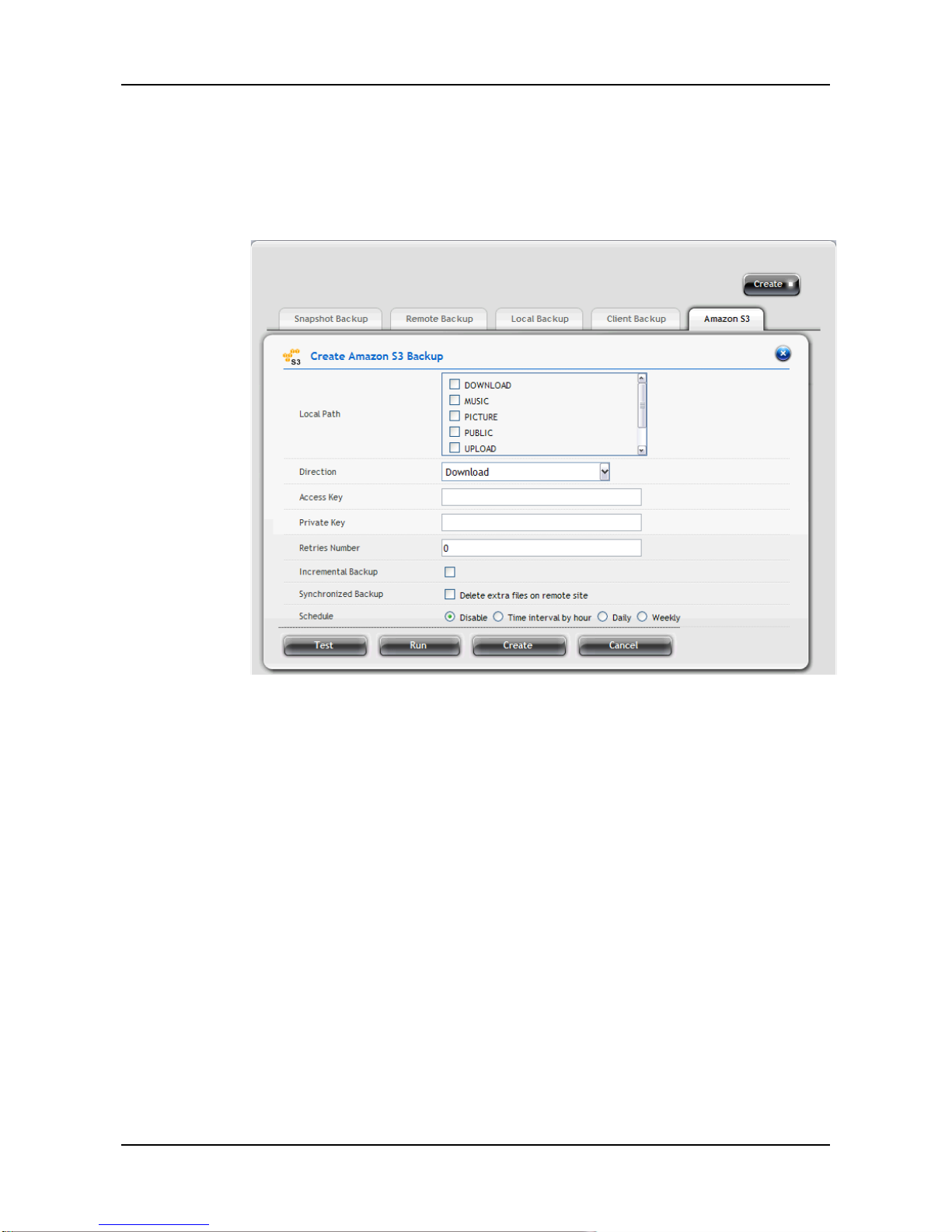
ShareCenter Pro User Manual
84
• Amazon S3 allows you to upload backup files to Amazon S3 server.
1. Click NAS tab > Backup > Amazon S3 tab.
2. Click the Create button and complete the required settings in
the Create Am azon S3 Backup window.
− Local Path
− Direction: Select Download (from Amazon S3 to device) or
Upload (from device to Amazon S3).
− Access Key: Ent er the Access key for the Amazon S3
server.
− Private key: Enter the Private key for the Amazon S3
server.
− Retries Number
− Increment Backup: Select this option and the backup will
add the updated files only.
− Synchronized Backup: Select this option and the backup
will delete the extra files while synchronizing.
− Schedule: Select one of the schedule types you want for
the backup solution.
Disable – no snapshots will be taken.
Time interval by hour – snapshots will be taken at the
Page 85
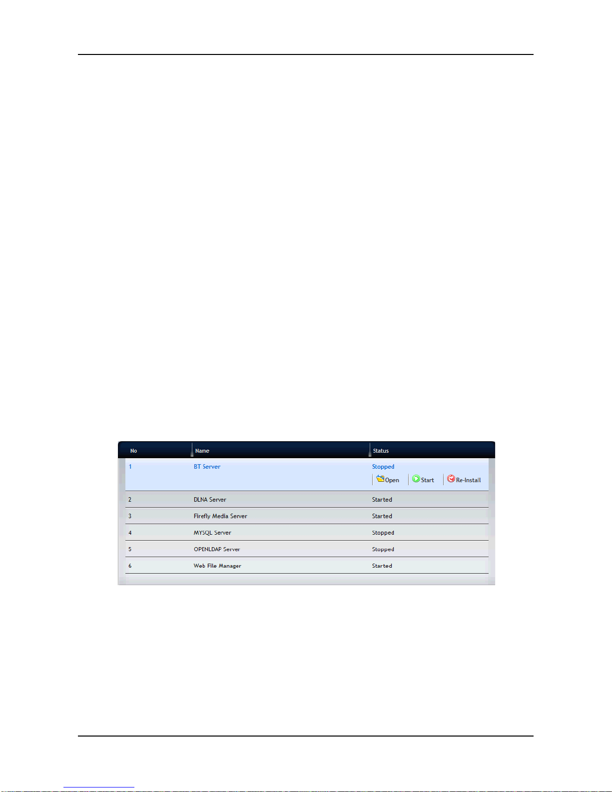
85
hourly interval you choose from the dropdown menu.
Daily – snapshots will be taken at the time of day you
choose from the dropdown menus .
Weekly – snapshots will be taken on the day of the
week, at the time of day you choose from the dropdown
menus.
3. When done, click the Run button. The new backup schedule is
applied.
You can click the Test button to test the server before applying
the settings.
4. T o change the settings of the backup solution, move you mouse
over the item you want and click the option button.
3.6.7 Plug-in Management
1. Click NAS tab > Plug-in.
2. Click the Add button to add a plug-in for the NAS:
a. Click the “Choose File” button to locate the plug-in file.
b. Click the Install button to start installing the plug-in.
3. In the Plug-in list, move your mouse over the item and you can:
− Display the plug-in application in a new win dow by clicking the
Open button.
− Stop the plug-in application by clicking the Stop button.
− Re-install the plug-in application by clicking the Re-Install
button.
Page 86
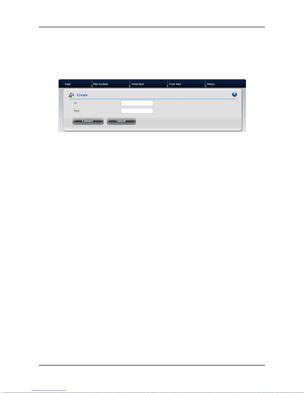
ShareCenter Pro User Manual
86
3.6.8 iSCS I In itiator
1. Click NAS tab > iSCSI Initator.
2. Click the Create and complete the required settings in the Create
Snapshot window.
− IP
− Port
3. When done, click the Connect button. After successful logon, you can
start to use the disk volume on ShareCenter
®
Pro DNS-1550-04 as a
virtual drive on your compu ter.
Page 87
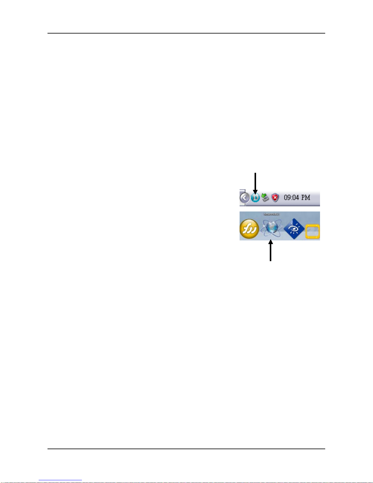
87
Chapter 4: ShareCenter® NAVI
4.1 Working with ShareCenter® NAVI
The ShareCenter® NAVI software connects your PC to the ShareCenter®
Pro DNS-1550-04, performs backups, changes the network settings,
create RAID volumes, add and mounts folders, and manages file
downloads from the Internet.
4.1.1 Opening the Main Wi ndow
1. To open the Main Window, do the
following actions :
• If neither Window is open Double-click the ShareCenter
®
NAVI
icon in the Windows application tray
or Mac Dock (right).
• If the ShareCenter
®
NAVI Window is open -
Double-click a system in the Device List.
ShareCenter®
NAVI i n
ShareCenter® NAVI
in Mac OS X
Page 88
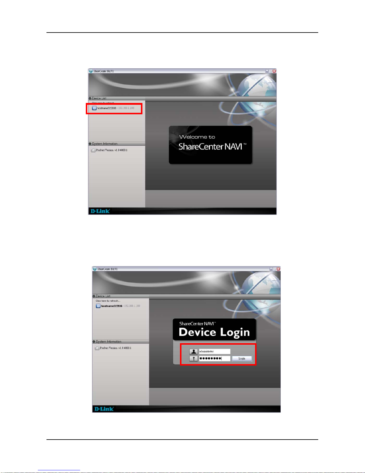
ShareCenter Pro User Manual
88
2. When the ShareCenter® NAVI Window opens, double-click a
system in the Device List.
3. When the login window appears, enter the user name and
password. Click Login then Yes to login the system.
The default user name is “administrator” and default password is
“password”. The user name and password are case sensitive.
Page 89
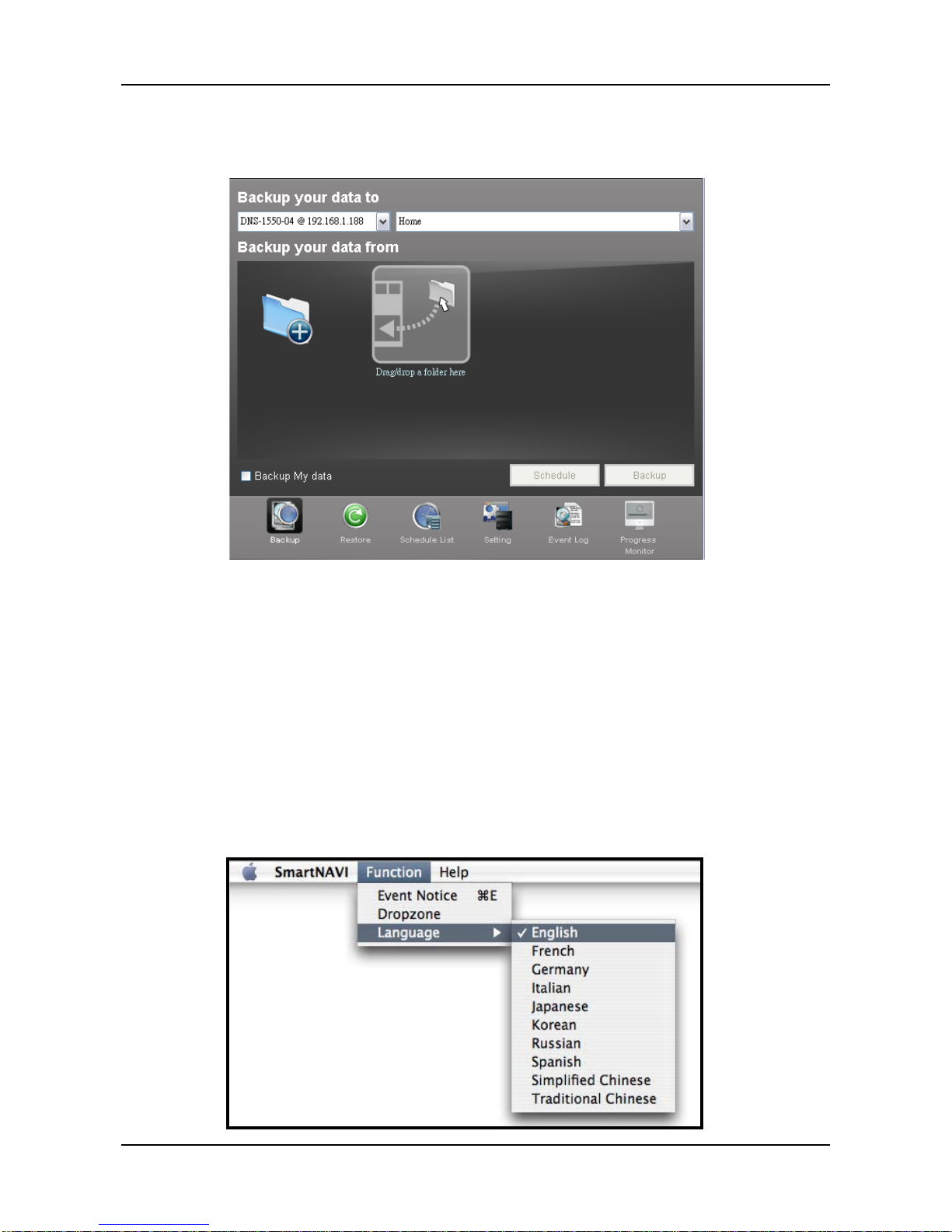
89
4. The Main Window opens, which contains the management
features of ShareCenter
®
NAVI.
4.1.2 Choosing a ShareCenter® NAVI Language
On Windows PCs, ShareCenter® NAVI chooses the display language
automatically based on your OS language setting. On Macs, you choose
the display language.
To choose a language:
1. Open the ShareCenter
®
NAVI Window.
2. From the dropdown menus, choose Function > Language, then
choose the the language you prefer.
Page 90
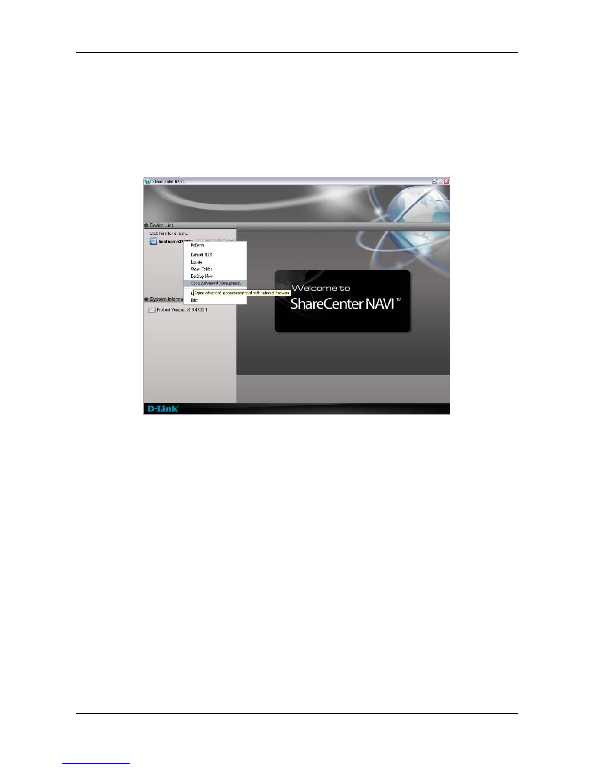
ShareCenter Pro User Manual
90
4.1.3 Starting the Advanced Storage Manager
This feature opens Advanced Storage Manager in your default browser.
Main Window
1. Right-click the system in the Device List that you want to open in
ASM.
Page 91
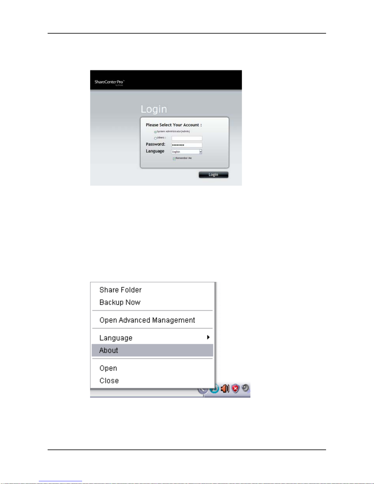
91
2. Choose the Open Advanced Management item. The ASM login
screen appears in your browser.
4.1.4 Viewing ShareCenter® NAVI Information
ShareCenter® NAVI is the software application that connects your PC
with the ShareCenter
®
Pro DNS-1550-04 system.
To view information about ShareCenter
®
NA VI on Windows:
1. Right-click the ShareCenter
®
NAVI icon in the application tray.
2. Choose About from the popup menu.
To view information about ShareCenter
®
NAVI on Mac:
From the dropdown menus at the top of the screen, choose Help >
About.
Page 92
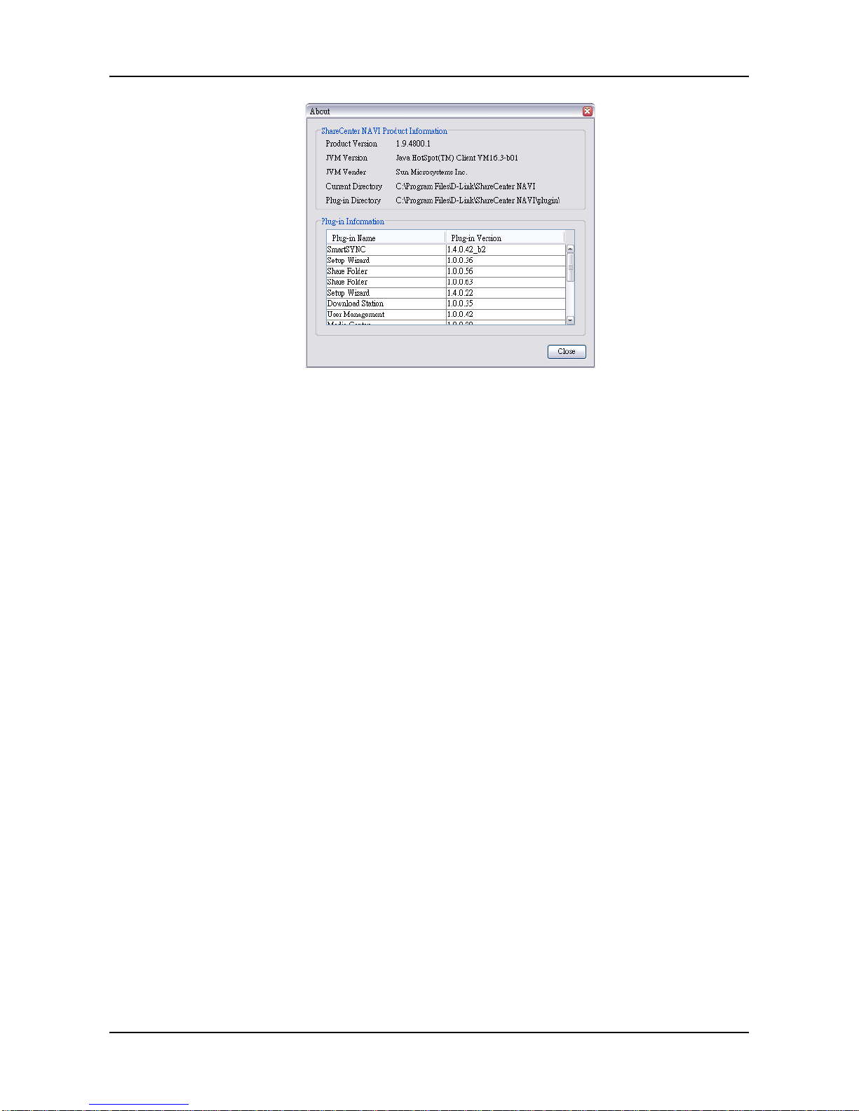
ShareCenter Pro User Manual
92
The About win do w appear s and lists the fol low ing information:
• ShareCenter
®
NAVI Version number
• Java Virtual Machine (JVM) Version number
• JVM Vendor name
• ShareCenter
®
NAVI installation direct ory on your PC
• ShareCenter
®
NAVI Plug-in directory on your PC
• Names of installed Plug-ins
• Version numbers of installed Plug-ins
When you are done with the About window, click the Close button.
Page 93
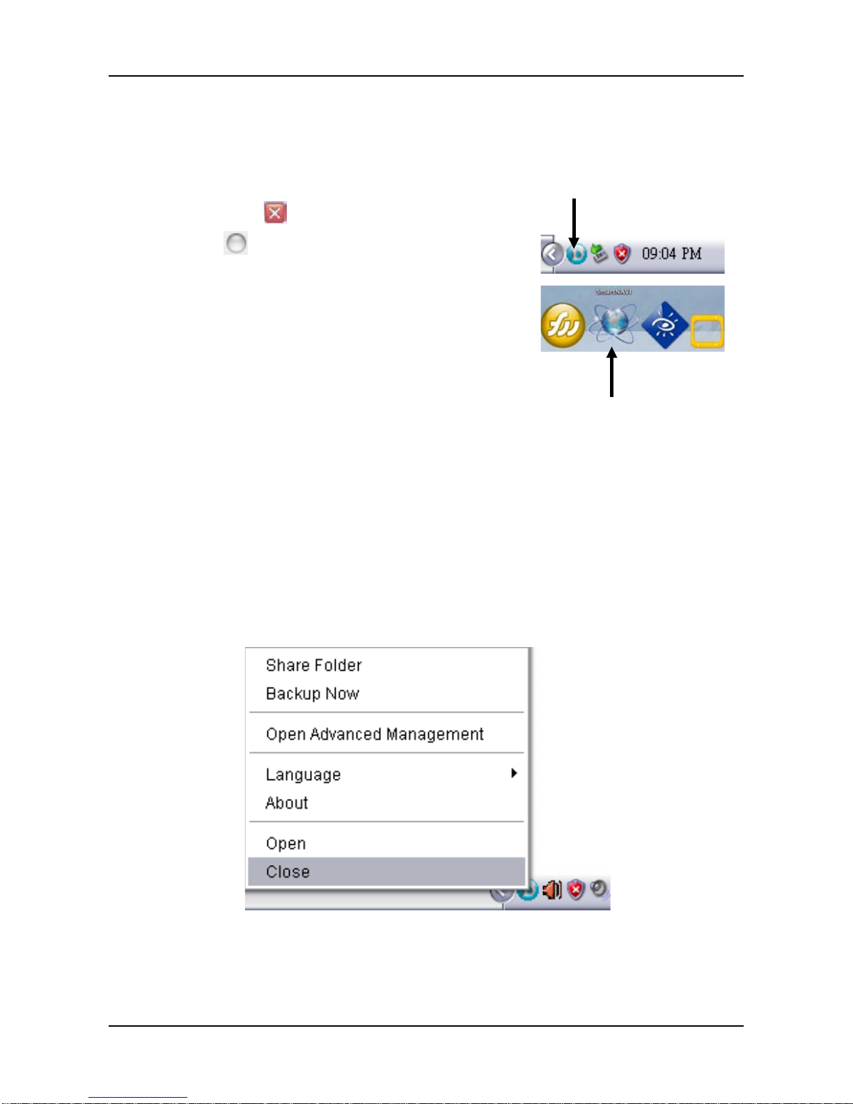
93
4.1.5 Closing ShareCenter® NAVI
To close ShareCenter® NAVI:
Click the close icon on the Main Window.
• Windows icon in the top right corner
• Mac icon in the top left corner
For Windows PCs, if you close
ShareCenter
®
NAVI this way, you can
open it from the application tray icon.
On Macs, you can always open
ShareCenter
®
NAVI from the Dock
icon.
Alternative Method for Windows
To close ShareCenter
®
NAVI:
1. Right-click the ShareCenter
®
NAVI icon in the application tray.
2. Choose Close from the popup menu.
ShareCenter®
NA VI in Windows
ShareCenter® NAVI
in Mac OS X
Page 94
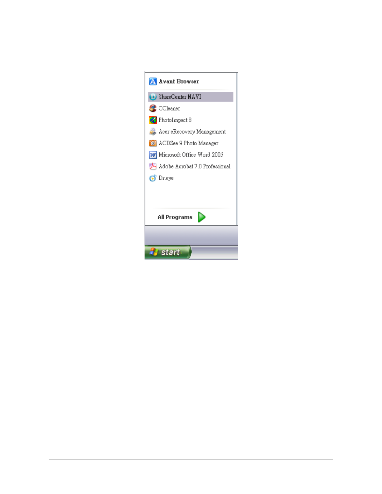
ShareCenter Pro User Manual
94
If you close ShareCenter® NAVI this way, you must open it from the Start
menu.
Page 95

95
4.2 Managing Back ups
Caution
Please do not close the ShareCenter
®
Pro NAVI or log
out of the MS Windows system while you are setting a
scheduled back up or running the backup process. It will
discontinue the backup process.
4.2.1 Doing a Backup Now
This feature enables you to perform an immediate scheduled backup of
your files from your Windows or Mac to the NAS system (ShareCenter
®
NAVI).
You can perform an immediate backup of your files from:
• ShareCenter
®
NAVI Main W indow
• ShareCenter
®
NAVI Device List
• ShareCenter
®
NAVI tray icon (Windows PCs only)
• One Touch Button
Main Window
If you do not have a backup schedule for your PC, start your backup
from the ShareCenter
®
NA VI Main Window .
1. Go to the Main Window.
2. Click the SmartSYNC icon.
3. Click the Backup button.
4. Under Backup your data to, choose:
Page 96
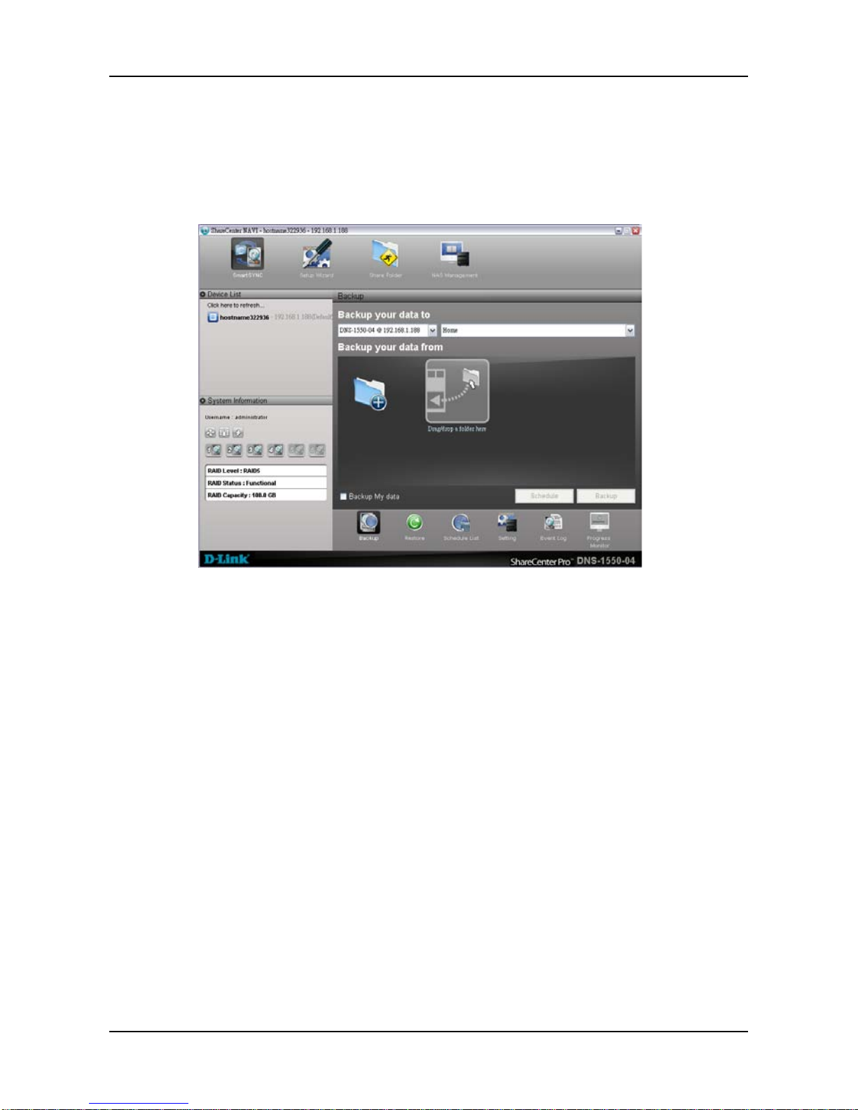
ShareCenter Pro User Manual
96
• The NAS or Local drive (your PC or MAC) from the first dropdown
menu.
• The letter designation of your PC or MAC drive under the second
dropdown menu.
5. Do any of the following actions to select your backup folders:
Page 97
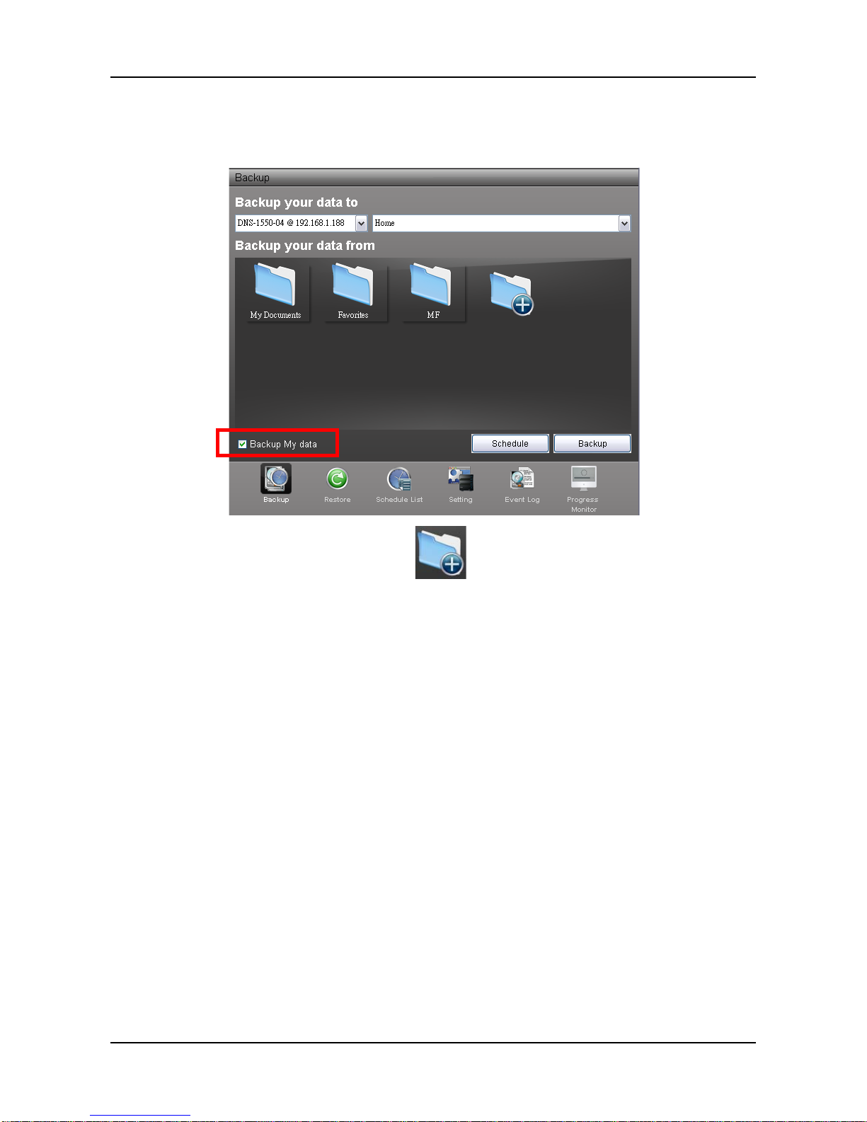
97
• Check the Backup My Data box – Selects the My Documents,
Favorites, and Desktop folders with all their contents.
• Click the Add to Backup icon – Opens the My
Documents folder. Click a folder you want to backup, and then click
the Choose button. Repeat for additional folders.
Page 98
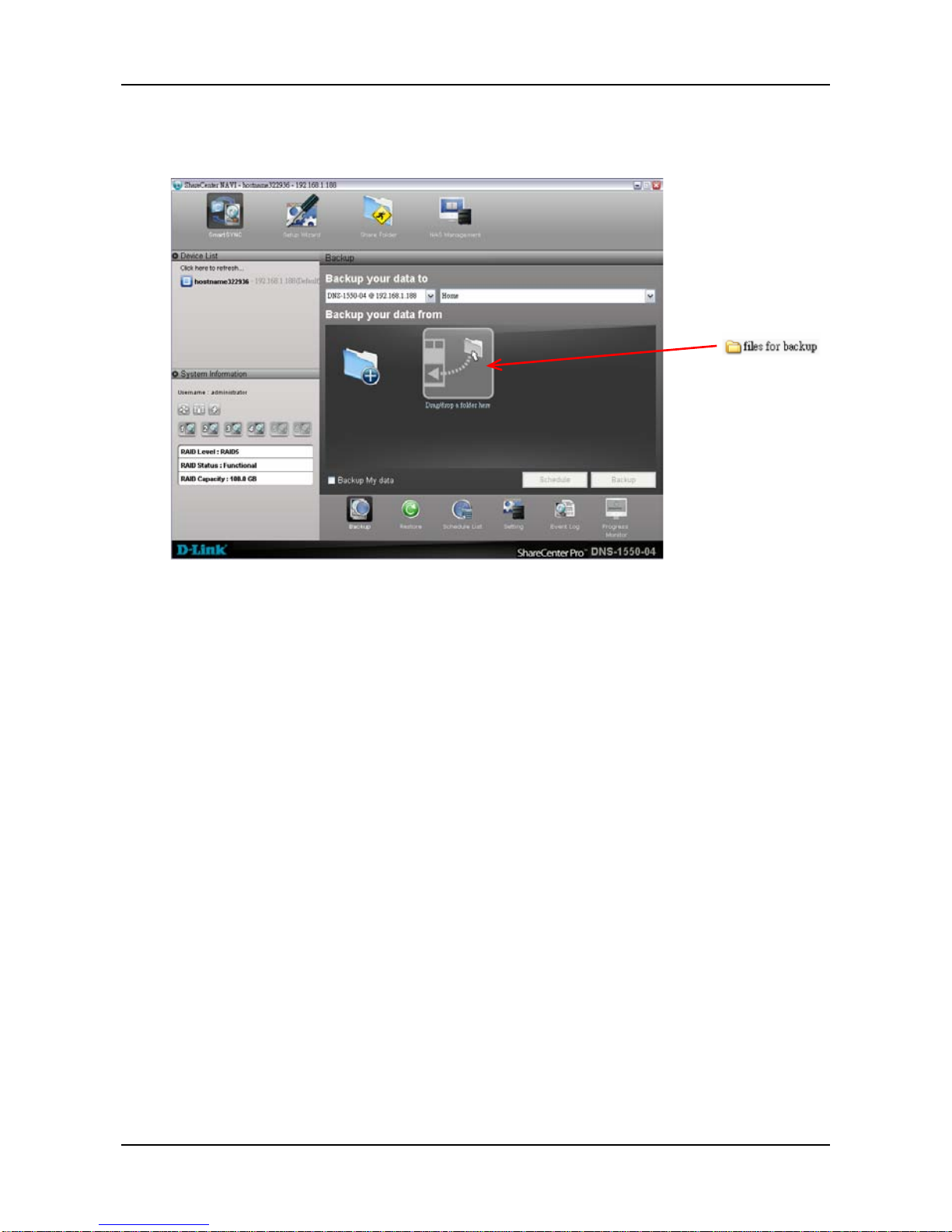
ShareCenter Pro User Manual
98
• Drag and drop the folders you want to backup to the Backu p you r
data from window.
6. Click the Backup button.
The backup begins immediately.
Device List
Before you can do a backup from the ShareCenter
®
NA VI Main Window,
you must create a backup schedule.
1. Go to the Main Window.
2. Right-click the system in the Device List whose backup you want
to run.
3. Choose the Backup Now item.
Page 99
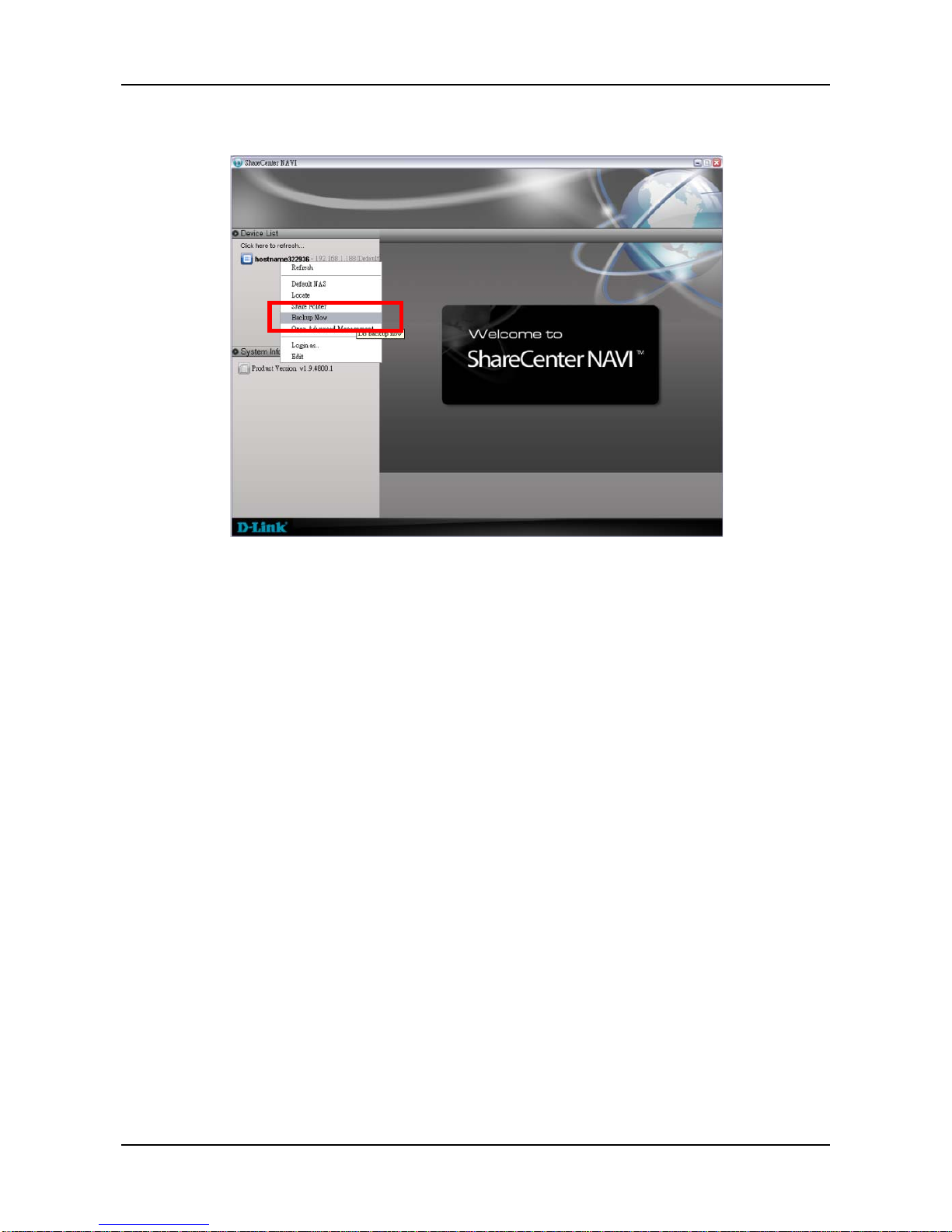
99
The backup begins immediately.
Tray Icon
Before you can do a backup from the ShareCenter
®
NAVI tray icon, you
must create a backup schedule and setup default NAS first. This feature
applies to Windows PCs only.
1. Right-click the ShareCenter
®
NAVI icon in the application tray.
2. Choose Backup Now in the popup menu.
The backup begins immediately.
The amount of time required depends on the size and number of files
being backed up.
The backed up files will appear on the NAS system (ShareCenter
®
NAVI)
in a folder named BACKUPDATA_your username.
You can restore the backup files to your PC at any time.
See “Restoring Backed-up Files” on page 107.
Page 100
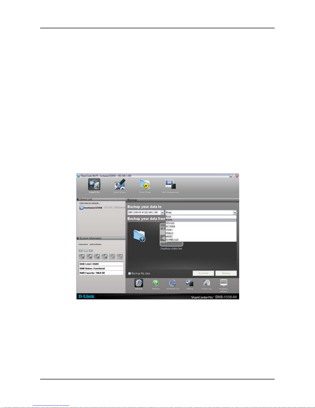
ShareCenter Pro User Manual
100
4.2.2 Scheduling a Backup
You can schedule backups by the hour, day, or week.
To set a schedule for backing up files from your PC to the NAS system
(ShareCenter
®
NAVI):
1. Go to the Main Window.
2. Click the SmartSYNC icon.
3. Click the Backup button.
4. Under Backup your data to, choose:
• The NAS or Local drive (your PC or MAC) from the first
dropdown menu.
• The letter designation of your PC or MAC drive under the
second dropdown menu.
5. Do any of the following actions to select your backup folders:
 Loading...