

Page 1

Before Your Begin
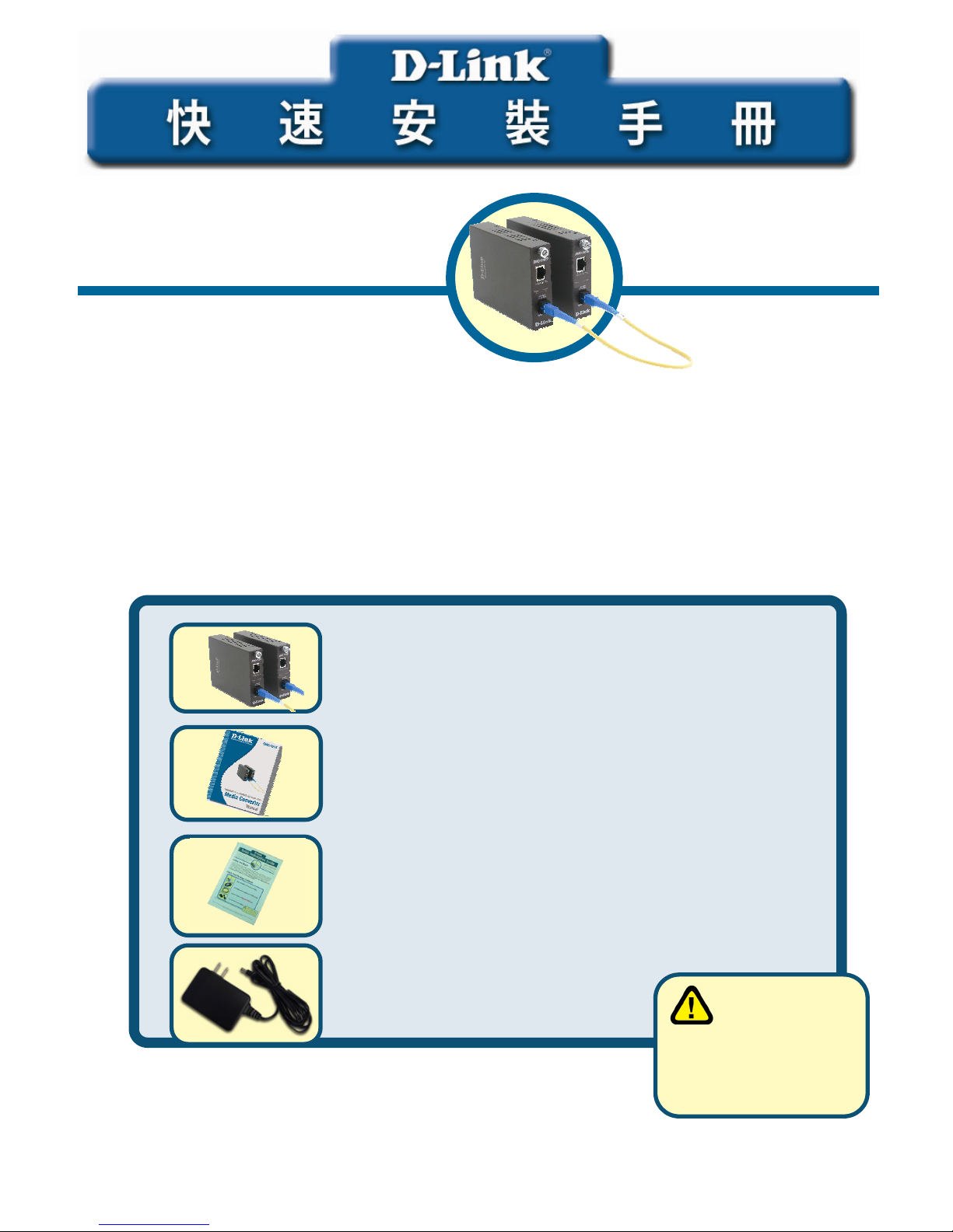
This Quick Installation Guide gives step-by-step instructions for setting up the D-Link DMC1910 1000BASE-TX to 1000BASE-LX Single-Fiber Dual-Wavelength Media Converter Kit. The
model you have purchased may appear slightly different from those shown in the illustrations.
For more detailed information about the media converter, its components, making network
connections and technical specifications, please refer to the User’s Manual included with your
media converter.
Check Your Package Contents
These are the items included with your DMC-1910 purchase:
If any of the above items are missing, please contact your reseller.
©2005 D-Link Systems, Inc. All rights reserved. Trademarks or registered trademarks are the property of their respective
holders. Software and specifications subject to change without notice.
DMC-1910
1000BASE-TX to 1000BASE-LX
Single-Fiber Media Converter Kit
• DMC-1910R and DMC-1910T 1000BASE-TX to
1000BASE-LX Single-Fiber Dual-Wavelength
Media Converter Kit
• User Manual
• Quick Installation Guide
• 7.5V DC, 1.5A Power Adapter
Using a power
supply with a
different voltage rating
will damage and void
the warranty for this
product.
Page 2
2
Setup The DMC-1910 Single Fiber
Media Converter
As with any electric device, you should place the equipment where it will
not be subjected to extreme temperatures, humidity, or electromagnetic
interference. Specifically, the site you select should meet the following
requirements:
A. The ambient temperature should be between 32 and 104 degrees
Fahrenheit (0 to 40 degrees Celsius).
B. The relative humidity should be less than 90 percent, non-condensing.
C. Surrounding electrical devices should not exceed the electromagnetic
field (RFC) standards for IEC 801-3, Level 2 (3V/M) field strength.
D. Make sure that the equipment receives adequate ventilation. Do not
block the ventilation holes on each side of the media converter or the
fan exhaust port on the side or rear of the equipment.
E. The power outlet should be within 1.8 meters of the switch.
Connecting the power
1. This Converter is a plug-and-play device.
2. Connect the supplied AC to DC power adaptor with a power voltage
of 7.5Vdc/1.5Amp to the receptacle on the rear panel of the converter,
and then attach the plug into a standard AC outlet with a voltage
range from 100 to 260 Vac.
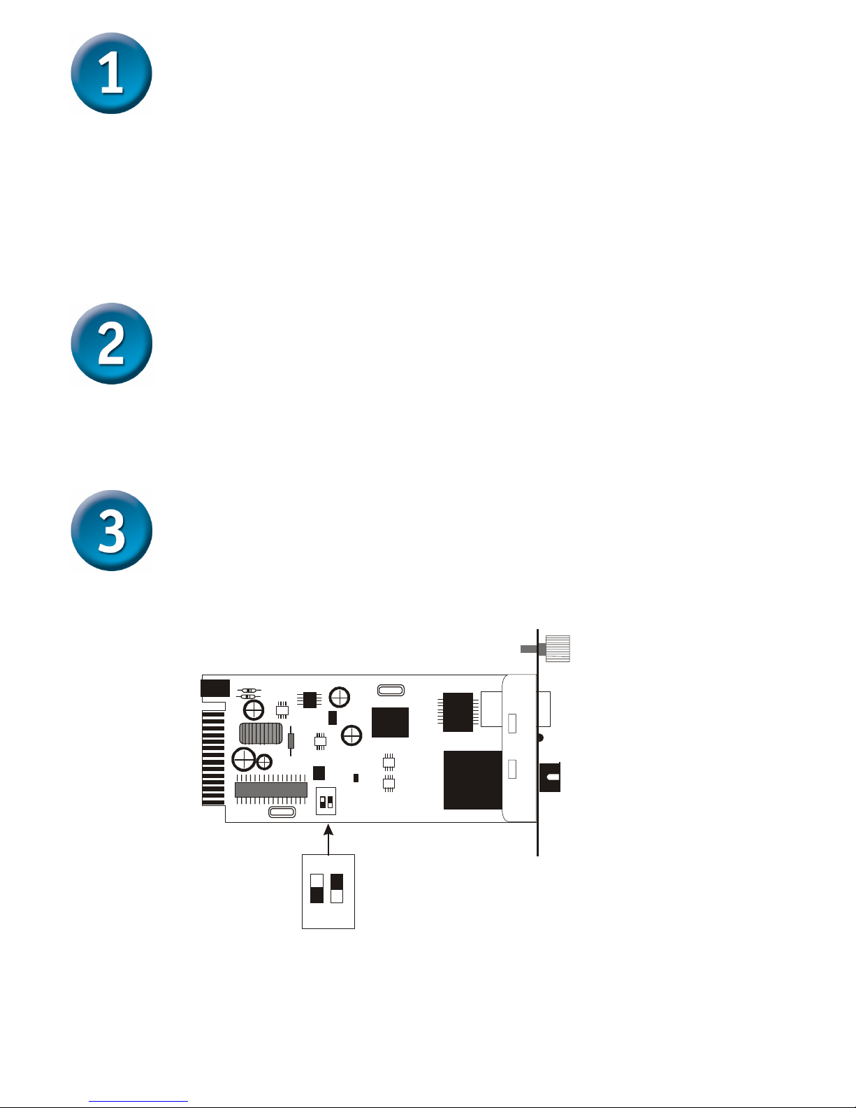
Sliding Switch
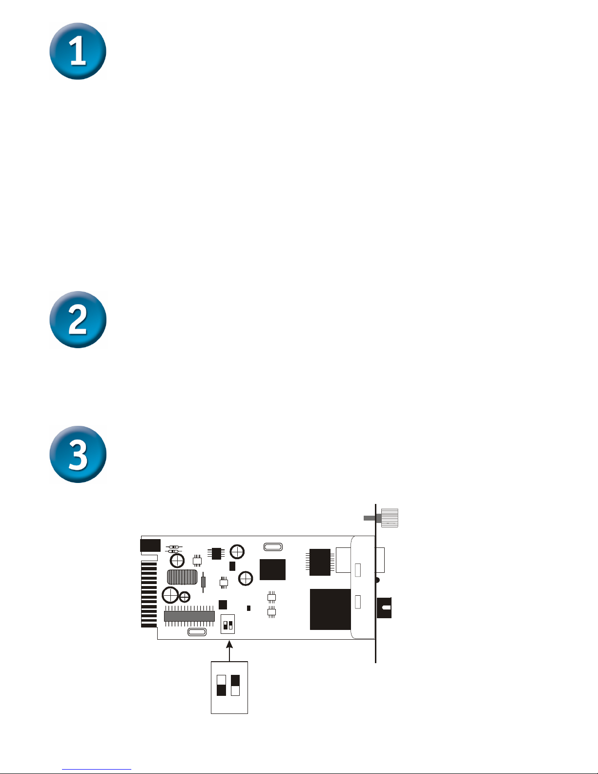
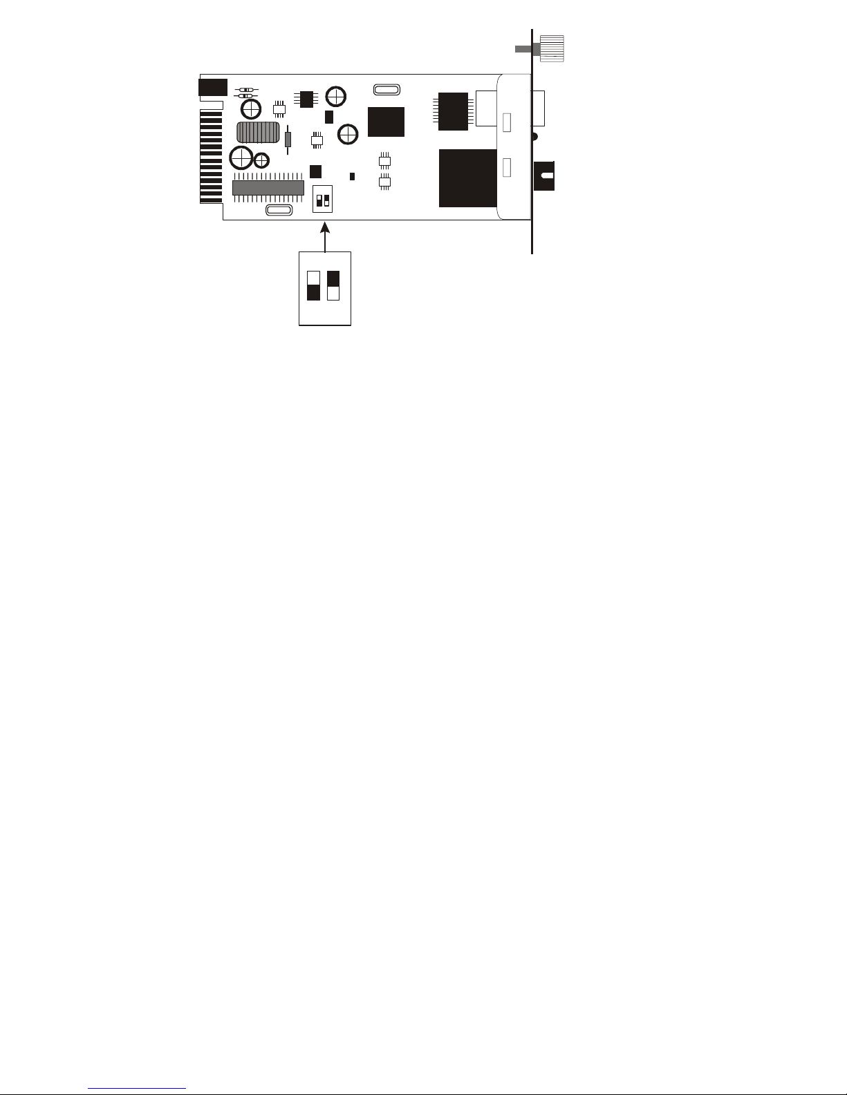
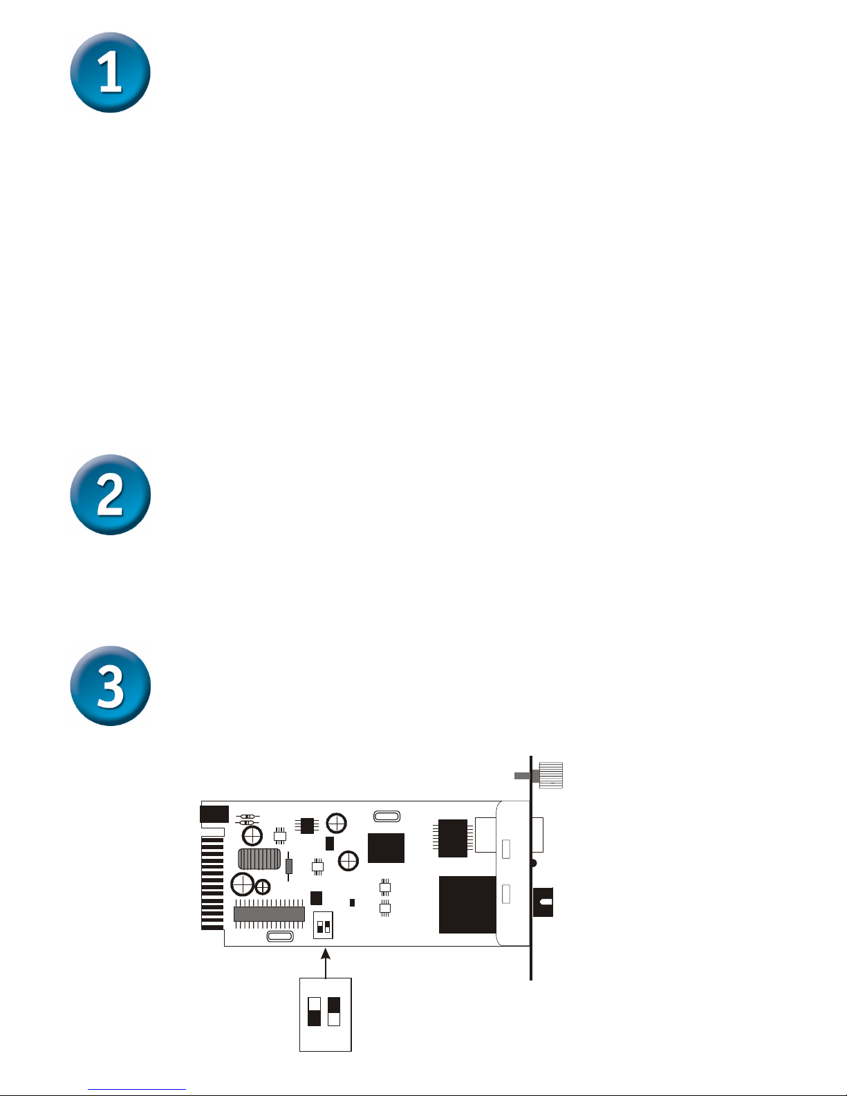
There is a two pin DIP switch on the module which define as switch 1 and switch 2:
Sw itch 1 : O n - > Forced M ode
O ff -> A u to N e g o tia tio n m o d e
Sw itch 2 : O n - > LLR enable
O f f - > L L R d is a b le
12
on
12
on
Page 3
3
Switch 1: Fiber mode switch
When the switch was turned to “On”, it means that the fiber was turned to
forced mode, and “Off” for auto-negotiation mode.
Note: Be sure the opposite end is using the same setting (forced or Autonegotiation). And when using two converters at the same time, the two
converters MUST set to forced mode.
Switch 2: LLR
When the switch was turned to “On”, it means that the LLR was enabled and
“Off” for disabled.
Note: When using two converters, don’t enable the both devices’ LLR
function at the same time.
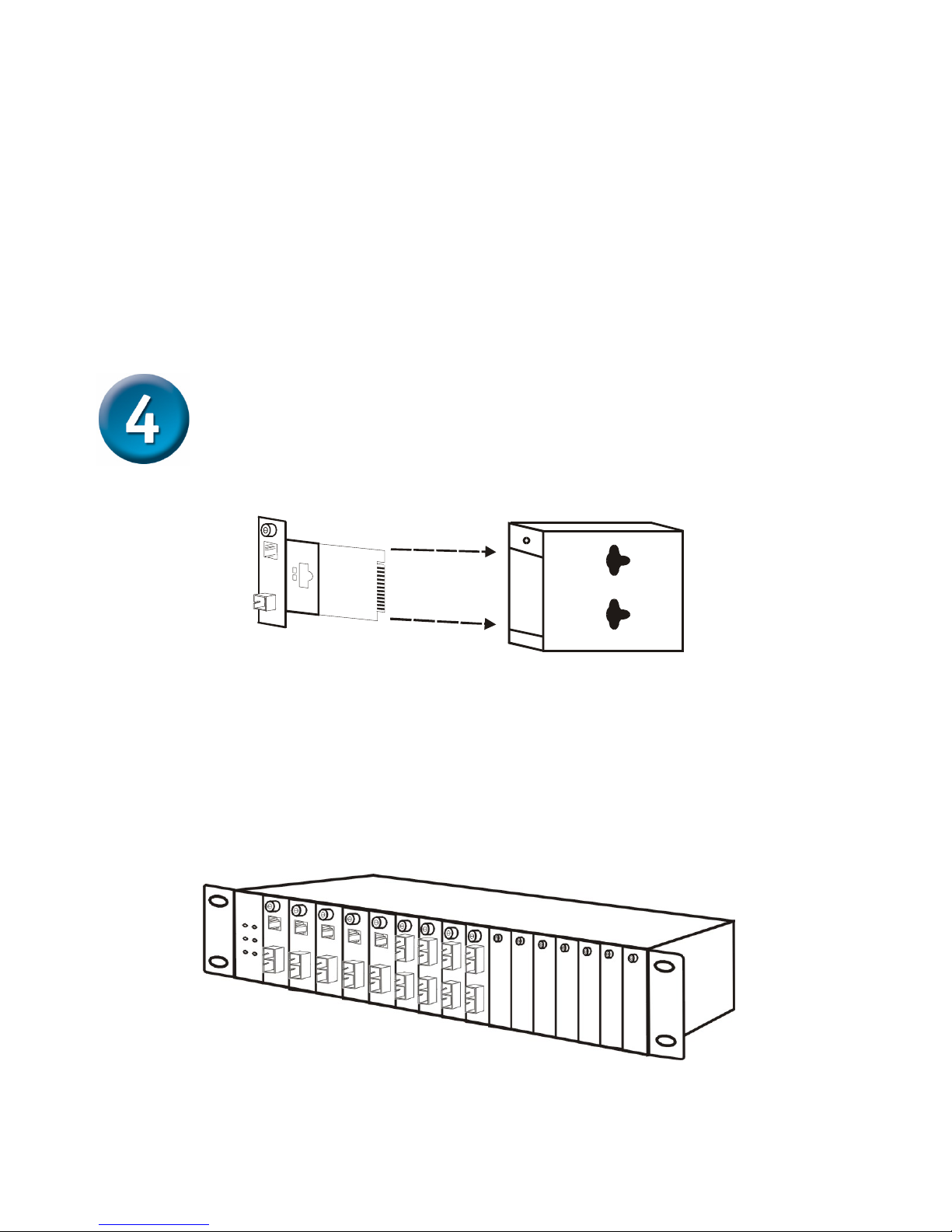
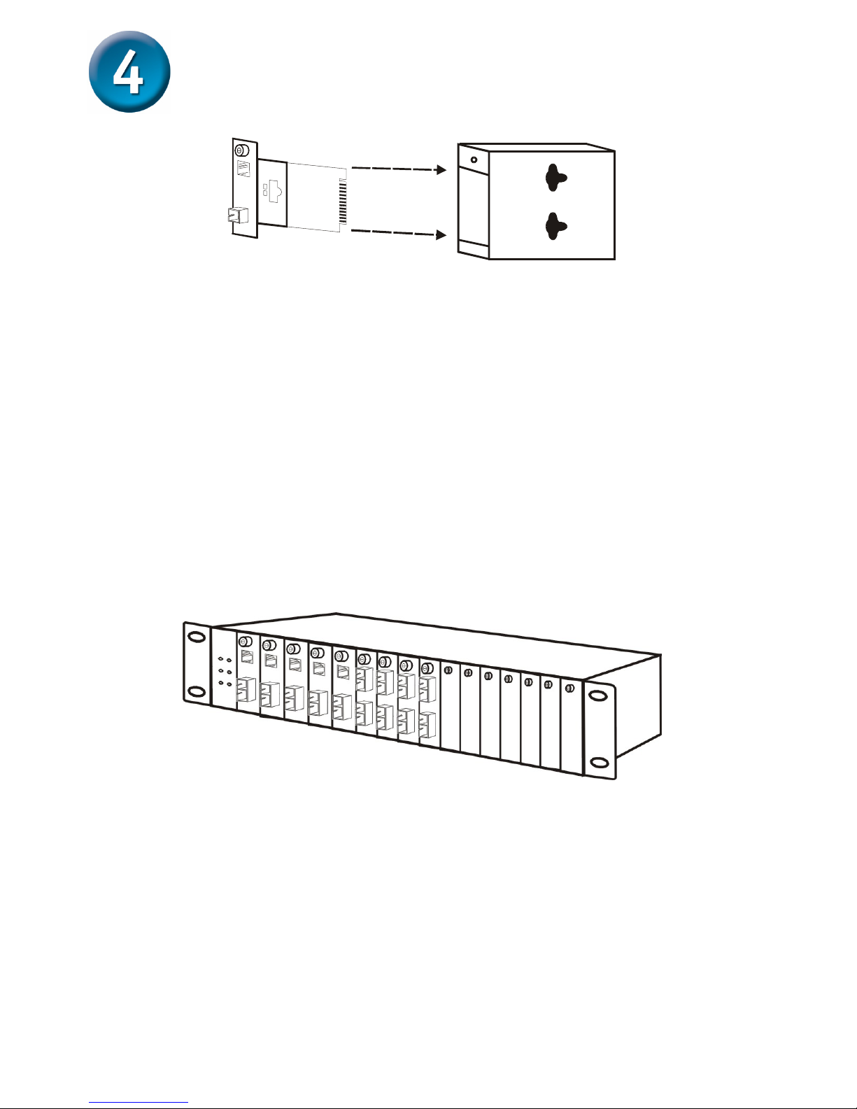
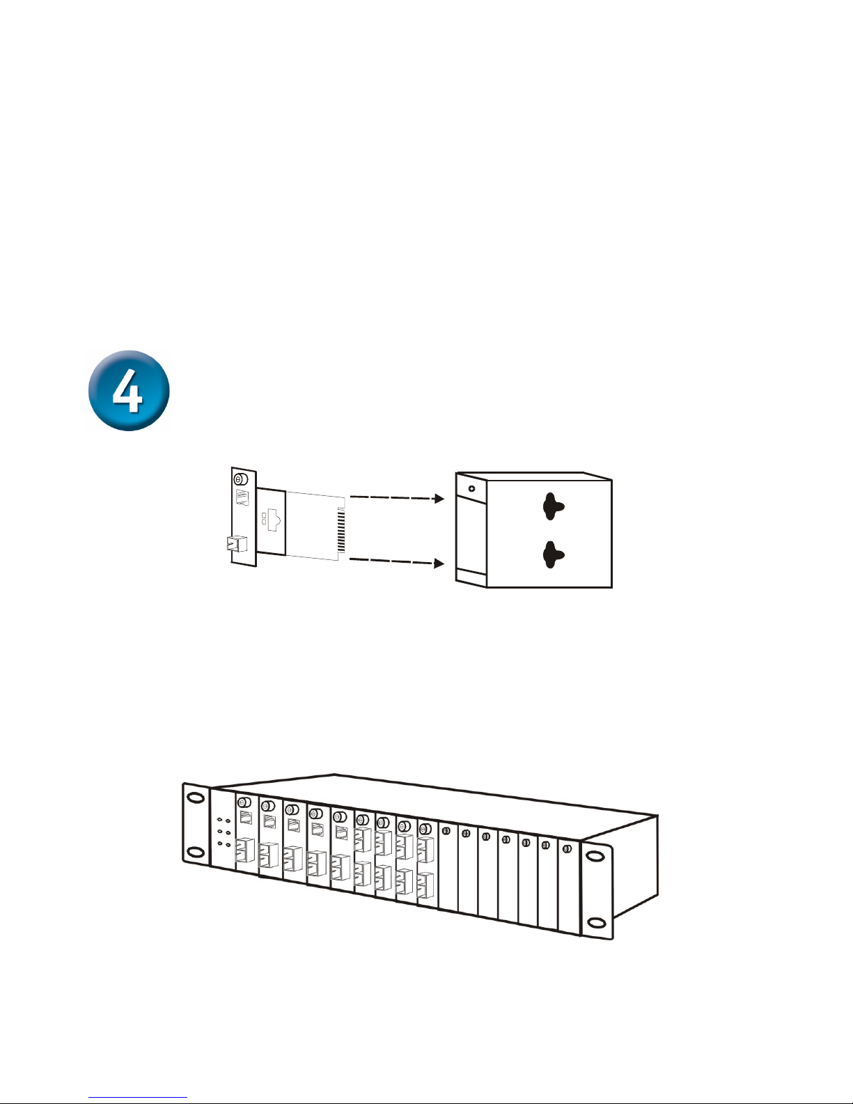
Installing in a Chassis
The Converter can be fit into any of the expansion slots on a special designed
chassis.
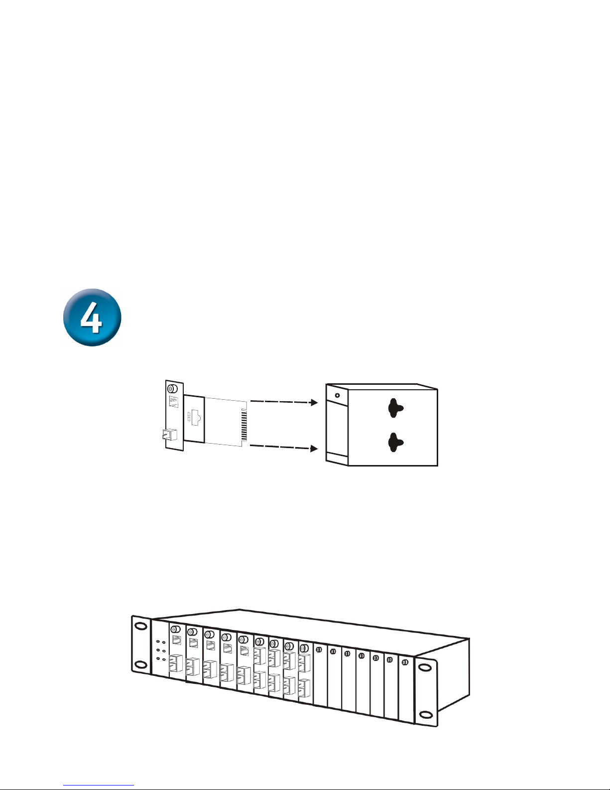
y First, install the converter onto a carrier supplied with the chassis:
Step 1- Unscrew the carrier from the desired expansion slot on the chassis.
Step 2- Remove the screw on the converter as shown below.
Step 3- Fit the converter onto the carrier and use the screw to secure it.
Unscrew and pull out the media converter board
Page 4
4
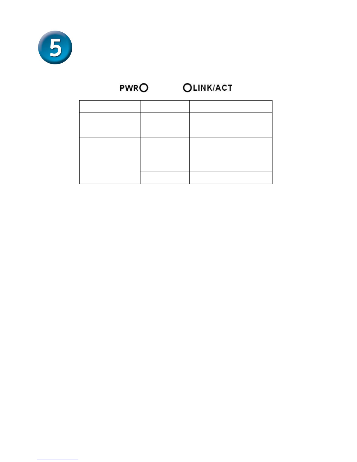
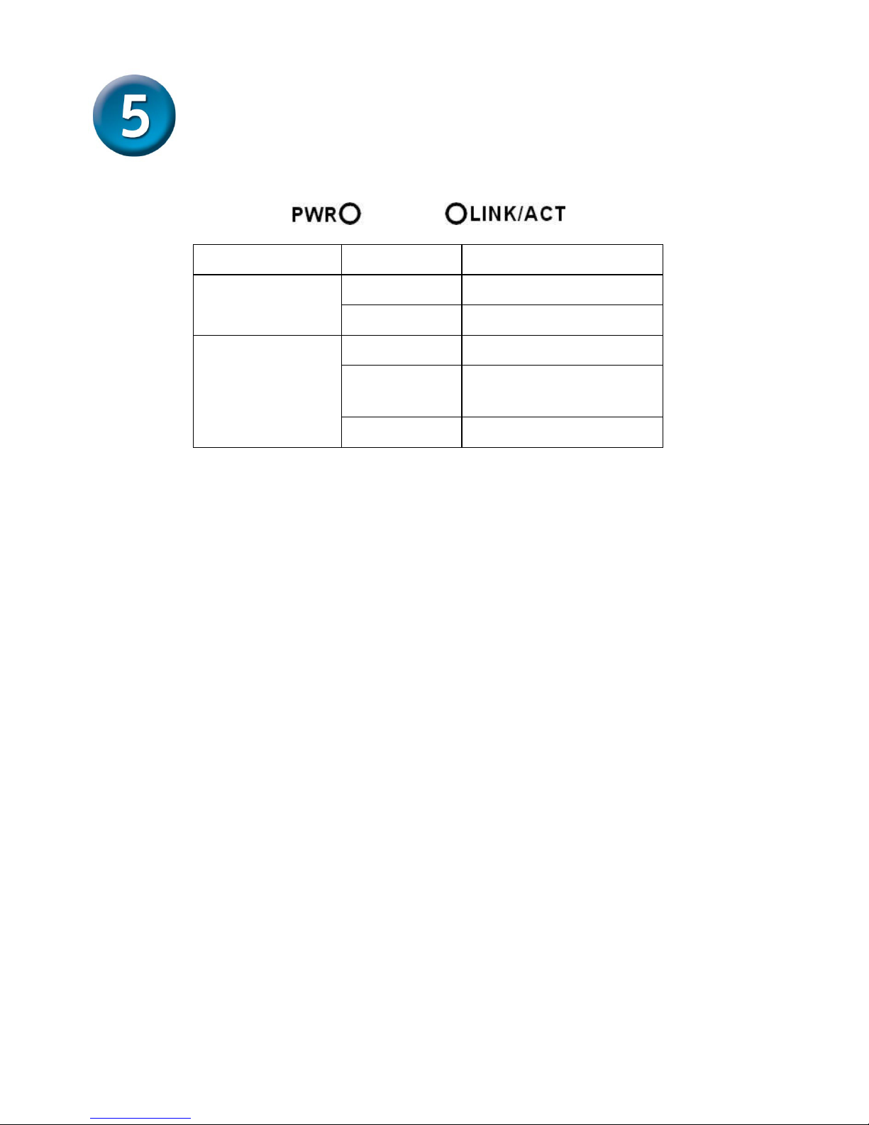
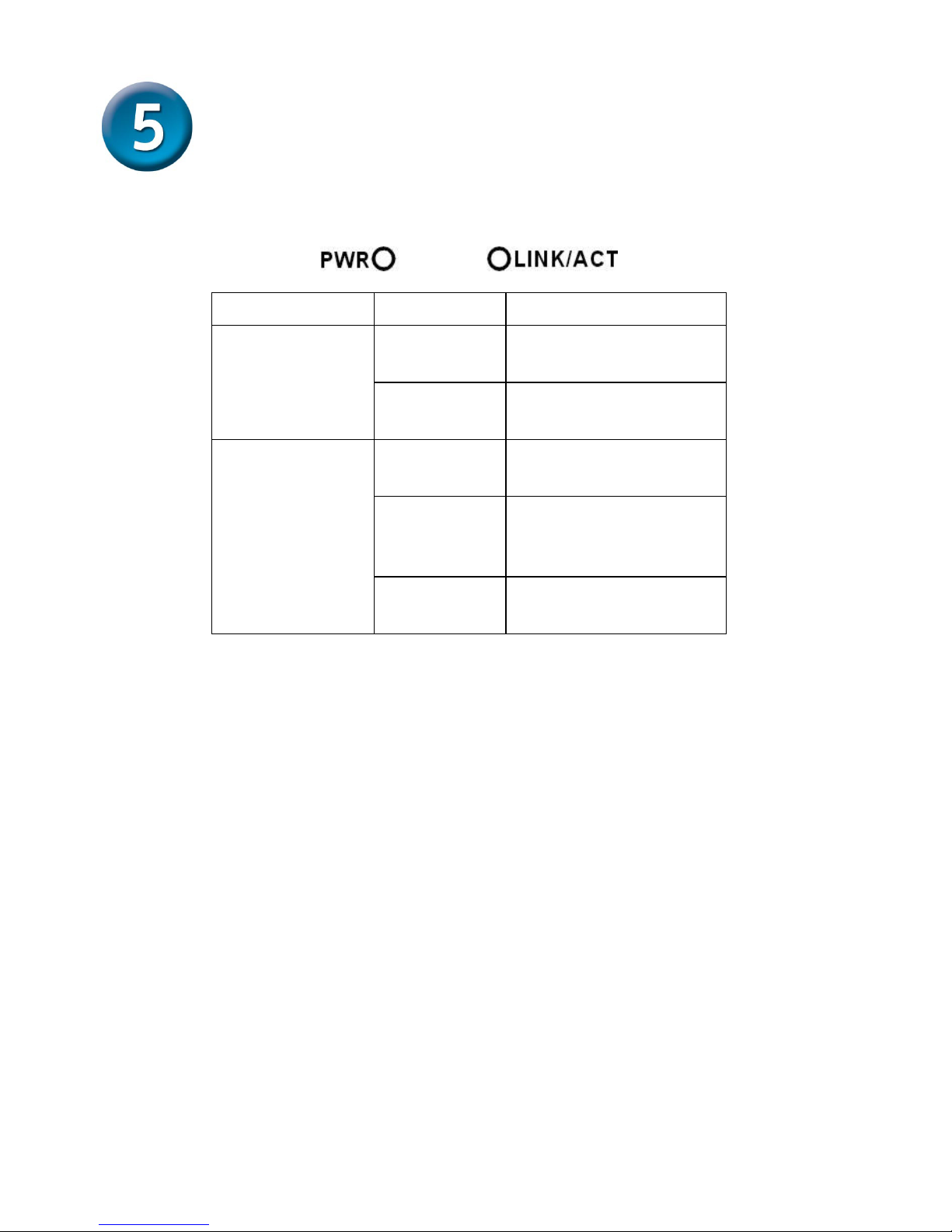
LED Indicators
The LED indicators give you instant feedback on status of the converter:
LEDs State Indication
Lights on Power on
Power
(PWR)
Lights off Power off
Lights on Linking
Lights
Blinking
Data transmitting and
receiving
Link and Activity
(LINK/ACT)
Lights off Not Linking
Page 5
5
Page 6
6
Technical Support
You can find software updates and user documentation on the
D-Link website.
Tech Support for customers within Australia:
D-Link Technical Support over the Telephone:
1300-766-868
Monday to Friday 8:00am to 8:00pm EST
Saturday 9:00am to 1:00pm EST
D-Link Technical Support over the Internet:
http://www.dlink.com.au
email:[email protected]
Tech Support for customers within New Zealand:
D-Link Technical Support over the Telephone:
0800-900-900
Monday to Friday 8:30am to 8:30pm
Saturday 9:00am to 5:00pm
D-Link Technical Support over the Internet:
http://www.dlink.co.nz
email:[email protected]
Page 7
7
Technical Support
You can find software updates and user documentation on the
D-Link website.
Tech Support for customers within South Eastern
Asia and Korea:
D-Link South Eastern Asia and Korea Technical Support
over the Telephone:
+65-6895-5355
Monday to Friday 9:00am to 12:30pm, 2:00pm-6:00pm
Singapore Time
D-Link Technical Support over the Internet:
email:[email protected]
Page 8
8
Technical Support
You can find software updates and user documentation on the
D-Link website.
Tech Support for customers within India
D-Link Technical Support over the Telephone:
+91-22-26526741
+91-22-26526696 –ext 161 to 167
Monday to Friday 9:30AM to 7:00PM
D-Link Technical Support over the Internet:
http://ww.dlink.co.in
http://www.dlink.co.in/dlink/drivers/support.asp
ftp://support.dlink.co.in
email: [email protected]
Page 9
9
Technical Support
You can find software updates and user documentation on the
D-Link website.
D-Link provides free technical support for customers for the
duration of the warranty period on this product.
Customers can contact D-Link technical support through our
web site or by phone.
Tech Support for customers within the Russia
D-Link Technical Support over the Telephone:
(095) 744-00-99
Monday to Friday 10:00am to 6:30pm
D-Link Technical Support over the Internet
http://www.dlink.ru
email: [email protected]
Page 10
10
Technical Support
You can find software updates and user documentation on the D-Link website.
Tech Support for customers within the U.A.E & North Africa:
D-Link Technical Support over the Telephone:
(971) 4-391-6480 (U.A.E)
Sunday to Wednesday 9:00am to 6:00pm GMT+4
Thursday 9:00am to 1:00pm GMT+4
D-Link Middle East & North Africa
D-Link Technical Support over the Internet:
http://support.dlink-me.com
email:[email protected]
Tech Support for customers within Israel:
D-Link Technical Support over the Telephone:
(972) 971-5701
Sunday to Thursday 9:00am to 5:00pm
D-Link Technical Support over the Internet:
http://www.dlink.co.il/forum
e-mail: [email protected]
Tech Support for customers within Turkey:
D-Link Technical Support over the Telephone:
(+90) 212-289 56 59
Monday to Friday 9:00am to 6:00pm
D-Link Technical Support over the Internet:
http://www.dlink.com.tr
e-mail: [email protected]
Tech Support for customers within Egypt:
D-Link Technical Support over the Telephone:
(202) 414-4295
Sunday to Thursday 9:00am to 5:00pm
D-Link Technical Support over the Internet:
http://support.dlink-me.com
e-mail: [email protected]
Page 11
11
Technical Support
You can find software updates and user documentation on the
D-Link website.
Tech Support for customers within South Africa
and Sub Sahara Region:
D-Link South Africa and Sub Sahara Technical Support
over the Telephone:
+27-12-665-2165
08600 DLINK ( For South Africa only )
Monday to Friday 8:30am to 9:00pm South Africa Time
D-Link Technical Support over the Internet:
http://www.d-link.co.za
email:[email protected]
Page 12
12
Technical Support
You can find updates and user documentation on the D-Link website
Tech Support for Latin America customers:
D-Link Technical Support over the followings Telephones:
Argentina: 0800-666 1442 Monday to Friday 09:00am to 22:00pm
Chile: 800-214 422 Monday to Friday 08:00am to 21:00pm
Colombia: 01800-700 1588 Monday to Friday 07:00am to 20:00pm
Ecuador: 1800-777 711 Monday to Friday 07:00am to 20:00pm
El Salvador: 800-6137 Monday to Friday 06:00am to 19:00pm
Guatemala:1800-300 0017 Monday to Friday 06:00am to 19:00pm
Panama: 0800-560 0193 Monday to Friday 07:00am to 20:00pm
Peru: 0800-52049 Monday to Friday 07:00am to 20:00pm
Venezuela: 0800-100 3470 Monday to Friday 08:00am to 21:00pm
D-Link Technical Support over the Internet:
www.dlinkla.com
www.dlinklatinamerica.com
email:[email protected]
Tech Support for customers within Brazil:
D-Link Technical Support over the Telephone:
0800-7014104
Monday to Friday 8:30am to 18:30pm
D-Link Technical Support over the Internet:
www.dlinkbrasil.com.br
email:[email protected]
Page 13
13
Прежде чем начать
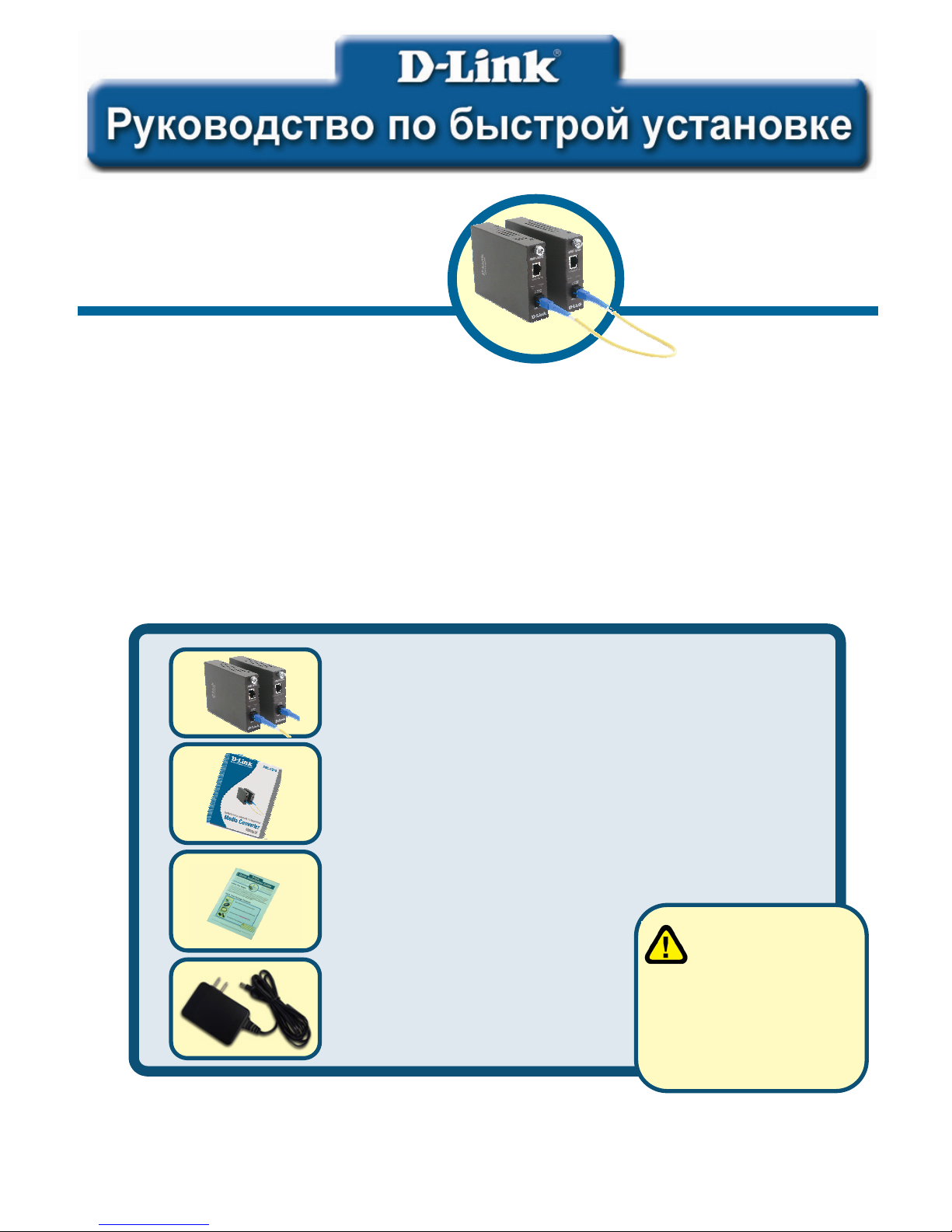
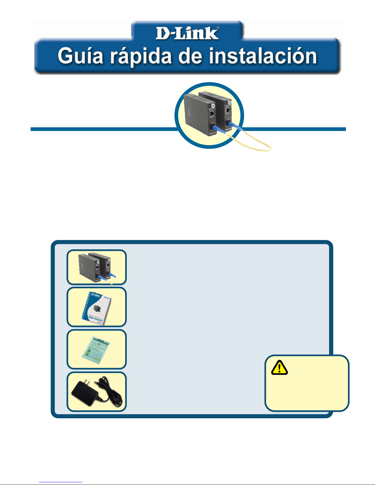
Это руководство по быстрой установке описывает пошаговые инструкции по настройке
комплекта одноволоконных медиаконвертеров для двух длин волн D-Link DMC-1910
1000BASE-TX на 1000BASE-LX. Модель, которую Вы приобрели, может незначительно
отличаться от показанной на иллюстрациях. За более подробной информацией о
медиаконвертере, его компонентах, настройке подключения к сети и технических
характеристиках, обращайтесь, пожалуйста, к руководству пользователя, включенному в
комплект поставки устройства.
Проверьте содержимое комплекта поставки
Эти компоненты включены в поставку DMC-1910:
Если что-либо из перечисленного отсутствует, обратитесь к вашему поставщику.
©2003 D-Link Systems, Inc. Все права защищены. Торговые марки или зарегистрированные торговые марки
являются собственностью их владельцев. Программное обеспечение и спецификации могут изменяться без
уведомления.
DMC-1910
Комплект одноволоконных
медиаконвертеров
10
0
0
BASE-TX на10
0
0
BASE-LX
• DMC-1910R и DMC-1910T комплект
одноволоконных медиаконвертеров для
двух длин волн 1000BASE-TX на
1000BASE-LX
• Руководство пользователя
• Руководство по быстрой установке
• Адаптер питания
7.5В постоянного тока,
1.5A
Использование
источника питания
с другими
характеристиками и
напряжением может
повлечь выход из строя
устройства и потерю
гарантии.
Page 14
14
Установка одноволоконного
медиаконвертора DMC-1910
Как и любое другое электрическое устройство, поместите
медиаконвертер там, где он не будет подвергнут действию высоких
температур, влажности, или электромагнитных помех. Место,
которое Вы выберите, должно удовлетворять следующим
требованиям:
A. Окружающая температура должна быть между 0° и 40° C..
B. Относительная влажность менее 90% , без образования
конденсата.
C. Окружающие электрические приборы должны соответствовать
стандарту IEC 801-3 (электромагнитные поля) и Level 2 (3/VM)
(сила электромагнитного поля)
D. Убедитесь, что место, где установлено устройство имеет хорошую
вентиляцию. Не блокируйте вентиляционные отверстия на
каждой стороне медиаконвертора, или выпускной канал
вентилятора на боковой или задней панели оборудования.
E. Электрическая розетка должна находиться в пределах 1.8 метра
от медиаконвертора.
Подключение питания
1. Медиаконвертер является устройством plug-and-play.
2. Подключите адаптер питания постоянного тока 7.5 В/1.5А,
входящий в комплект поставки к разъему питания на задней
панели медиаконвертора, затем включите его в стандартную
электрическую розетку с напряжением от 100 до 260В
переменного тока.
Переключатель на медиаконверторе
На плате медиаконвертора имеются 2 переключателя, которые обозначены
как «switch 1» и «switch 2»:
Page 15
15
Sw itch 1 : O n - > Forced M ode
O ff -> A u to N e g o tia tio n m o d e
Sw itch 2 : O n - > LLR enable
O f f - > L L R d is a b le
12
on
12
on
Переключатель 1: Переключатель оптического режима
Когда переключатель находится в положении “On”, оптический порт
переключен в фиксированный режим, положение “Off” переключает порт
в режим автосогласования.
Примечание: Убедитесь, что на противоположных концах линии связи
используются аналогичные настройки (фиксированный режим или
режим автосогласования). При использовании одновременно двух
медиаконвертеров, оба устройства ДОЛЖНЫ быть установлены в
фиксированный режим.
Переключатель 2: LLR
Когда переключатель находится в положении “On” – LLR активно, в
положении “Off” – LLR отключено.
Примечание: При использовании двух медиаконвертеров, не
активизируйте функцию LLR одновременно на обоих устройствах.
Page 16
16
Установка в шасси
Медиаконвертор может быть установлен в слот расширения
специально разработанного шасси.
y Сначала установите медиаконвертор в шасси:
Шаг 1- Открутите шуруп и снимете фальш-панель с нужного слота
расширения.
Шаг 2- Удали те шуруп на медиаконверторе, как показано ниже.
Шаг 3- Установите медиаконвертор в шасси и закрепите его.
Снимите корпус медиаконвертора
Page 17
17
Индикаторы
Индикаторы позволяют отслеживать состояние медиаконвертора:
Индикатор Состояние Описание
Горит Питание включено
Питание
(PWR)
Не горит Питание выключено
Горит Связь есть
Мигает
Передача и прием
данных
Связь и
активность
(LINK/ACT)
Не горит Связи нет
Page 18
18
Техническая поддержка
Обновления программного обеспечения и документация
доступны на Интернет-сайте D-Link.
D-Link предоставляет бесплатную поддержку для клиентов в
течение гарантийного срока.
Клиенты могут обратиться в группу технической поддержки
D-Link по телефону или через Интернет.
Техническая поддержка D-Link:
(095) 744-00-99
Техническая поддержка через Интернет
http://www.dlink.ru
email: [email protected]
Page 19
19
Antes de Comenzar
Esta guía de instalación rápida le instruirá paso a paso la configuración del convertidor de
medios D-Link DMC-1910 1000BASE-TX a 1000BASE-LX Monomodo. Las ilustraciones
mostrarán alterada la imagen del DMC-1910 no obstante el procedimiento corresponde a este
equipo. Para mas detalles acerca del Media Converter, sus componentes, conexiones de
redes y especificaciones técnicas consultar el manual de usuario incluido con el DMC-1910.
Verifique el contenido del paquete
Estos los ítems que debe contener el empaque de su DMC-1910
Si falta alguno de los ítems arriba descritos por favor contáctese con su distribuidor.
©2005 D-Link Systems, Inc. All rights reserved. Trademarks or registered trademarks are the property of their respective
holders. Software and specifications subject to change without notice.
DMC-1910
1000BASE-TX to 1000BASE-LX
Single-Fiber Media Converter Kit
• Convertidor de Medio DMC-1910 1000BASETX a 1000BASE-LX Monomodo
• Manual del Usuario
• Guía de instalación Rápida
• Transformador 7.5V DC, 1.5A
Utilizar un trans formador con
valores distintos a los
descritos puede dañar
el equipo y perder su
garantía
Page 20
20
Consideraciones al Instalar el DMC-1910.
Como cualquier dispositivo eléctrico el DMC-1910 no debe ser expuesto
a temperaturas extremas, humedad o interferencias electromagnéticas.
Específicamente el lugar seleccionado debe cumplir los siguientes
requisitos:
A. La temperatura ambiental debe estar entre los 32 y 104 grados
Fahrenheit (0 a 40 grados Celsius).
B. La humedad relativa debe ser menos que el 90%, no condensada.
C. Los dispositivos eléctricos circundantes no deben exceder los
estándares de campo electromagnético (RFC) para IEC 801-3 y
campos de fuerza Nivel 2 (3V/M).
D. Asegure una adecuada ventilación. No tapar agujeros de ventilación
de los lados del Convertidor de Medios ni el extractor del ventilador.
E. El enchufe de energía debe estar a 1.8 metros del Switch.
Conectando la Energía
1. El convertidor de medios es un dispositivo Plu&Play.
2. Conecte el transformador en el receptáculo de la parte posterior del
DMC-1910 y el otro extremo en la línea eléctrica (100 a 260VAC).
Switch Deslizante
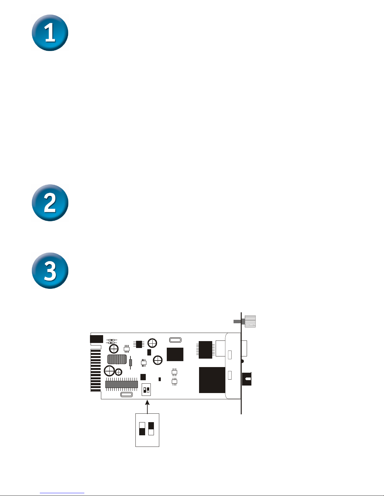
El DMC-1910 contiene un módulo con 2 Switch deslizantes definidos como
Switch1 y Switch2:
Sw itch 1 : O n - > Forced M ode
O ff -> A u to N e g o tia tio n m o d e
Sw itch 2 : O n - > LLR enable
O f f - > L L R d is a b le
12
on
12
on
Page 21
21
Switch 1: Switch Modo Fibra
Cuando el Switch está en “On”, este asume el modo forzado de fibra, en
“Off” asume el modo de auto negociación.
Nota: Cuando esté utilizando 2 Convertidores de medio asegúrese que el
lado opuesto esté utilizando la misma configuración (modo forzado o
autonegociación)
Switch 2: LLR
Cuando el switch este en “On”, el LLR ha sido habilitado, en “Off”
deshabilitado.
Nota: Cuando utilice 2 Convertidores de medio, no habilite el LLR en ambos
dispositivos a la vez.
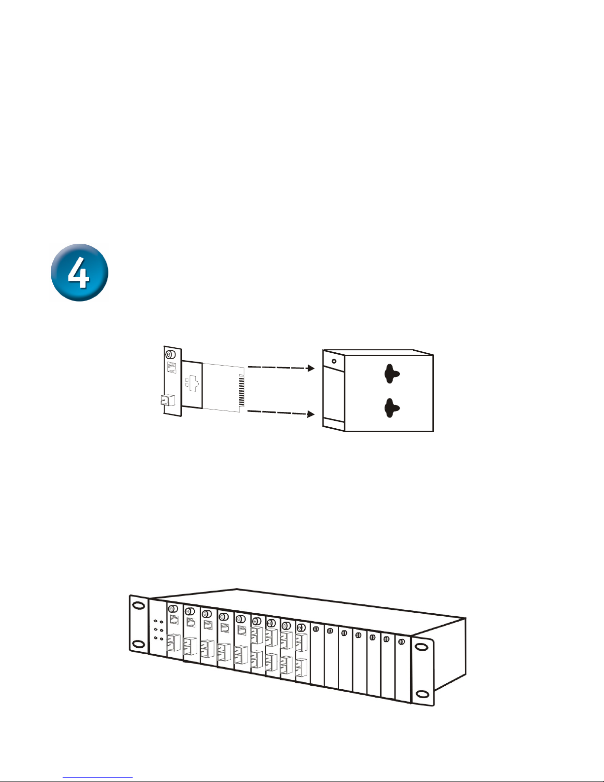
Instalación en el Chasis
El convertidor de medios puede ser instalado en cualquier spot de expansión
especialmente diseñado.
y Posicione el convertidor en el carrier o ranura suministrado en el chasis:
Paso 1- Desatornille la tapa del spot deseado en el chasis.
Step 2- Quitar los tornillos del Convertidor de medios.
Step 3- Ensamble el Convertidor de medios en el Chasis a través del carrier y fíjelo
con los tornillos.
Saque los tornillos y retire el Conversor.
Page 22
22
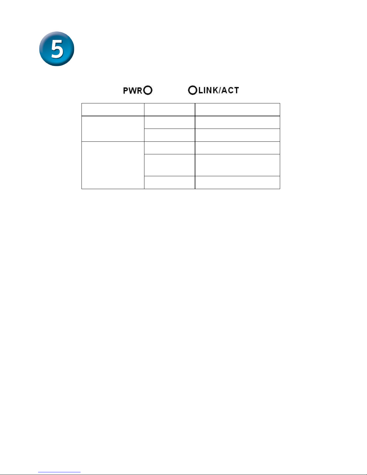
LED Indicadores
Los Led’s indican el estado o feedback del Convertidor de medios.
LEDs Estado Indica
Luz on Encendido
Alimentación
(PWR)
Luz off Apagado
Luz on Enlace
Luz
Pestañeando
Transmisión o
Recepción de Datos
Enlace y
Actividad
(LINK/ACT)
Luz off Sin enlace
Page 23
23
Page 24
24
Asistencia Técnica
D-Link Latin América pone a disposición de sus clientes, especificaciones,
documentación y software mas reciente a través de nuestro Sitio Web
www.dlinklatinamerica.com
El servicio de soporte técnico tiene presencia en numerosos países de la
Región Latino América, y presta asistencia gratuita a todos los clientes de
D-Link, en forma telefónica e internet, a través de la casilla
Soporte Técnico Help Desk Argentina:
Teléfono:
0800-6661442 Lunes a Viernes 09:00 am a 22:00 pm
Soporte Técnico Help Desk Chile:
Teléfono:
800-214422 Lunes a Viernes 08:00 am a 21:00 pm
Soporte Técnico Help Desk Colombia:
Teléfono:
01800-7001588 Lunes a Viernes 07:00 am a 20:00 pm
Soporte Técnico Help Desk Ecuador:
Teléfono:
1800-777 711 Lunes a Viernes 07:00 am a 20:00 pm
Soporte Técnico Help Desk El Salvador:
Teléfono:
800-6137 Lunes a Viernes 06:00 am a 19:00 pm
Soporte Técnico Help Desk Guatemala:
Teléfono:
1800-300 0017 Lunes a Viernes 06:00 am a 19:00 pm
Soporte Técnico Help Desk Panamá:
Teléfono:
0800-560 0193 Lunes a Viernes 07:00 am a 20:00 pm
Soporte Técnico Help Desk Perú:
Teléfono:
0800-52049 Lunes a Viernes 07:00 am a 20:00 pm
Soporte Técnico Help Desk Venezuela:
Teléfono:
0800-1003470 Lunes a Viernes 08:00 am a 21:00 pm
Page 25
25
Antes de você começar
Este Guia de Instalação Rápida fornece instruções passo a passo para configurar Kit
Conversor de Mídia Monofibra com Comprimento de Onda Dual 1000BASE-TX para
1000BASE-LX DMC-1910 da D-Link. O modelo que você adquiriu pode ter um aspecto
ligeiramente diferente dos mostrados nas ilustrações. Para informações mais detalhadas
sobre o conversor de mídia, seus componentes, estabelecimento de conexões de rede e
especificações técnicas, favor consultar o Manual do Usuário incluído com o seu conversor de
mídia.
Verifique o Conteúdo da sua Embalagem
Estes são os itens incluídos na compra do seu DMC-1910:
Se qualquer dos itens acima estiver faltando, favor contatar o seu revendedor.
©2005 D-Link Systems, Inc. Todos os direitos reservados. As marcas comercias ou marcas comerciais registradas são
propriedade dos seus respectivos detentores. Os softwares e especificações estão sujeitos a mudanças sem prévio aviso.
DMC-1910
Kit Conversor de Mídia Monofibra
1000BASE-TX para 1000BASE-LX
• Kit Conversor de Mídia Monofibra com
Comprimento de Onda Dual 1000BASE-TX
para 1000BASE-LX DMC-1910R e DMC-1910T
• Manual do Usuário
• Guia de Instalação Rápida
• Adaptador de Alimentação
7.5V DC, 1.5A
A utilização
de uma fonte de
alimentação com uma
classe de tensão diferente
irá danificar este produto e
anular sua garantia.
Page 26
26
Configurando o Conversor de Mídia
Monofibra DMC-1910
Como ocorre com qualquer dispositivo elétrico, você deverá colocar o
equipamento onde o mesmo não esteja exposto a temperaturas
extremas, umidade e interferência eletromagnética. Especificamente, o
local que você seleciona deve atender os seguintes requisitos:
A. A temperatura ambiente deverá estar entre 32 e 104 graus
Fahrenheit (0 a 40 graus Celsius).
B. A umidade relativa deverá ser inferior a 90%, sem condensação.
C. Os dispositivos elétricos vizinhos não deverão exceder os limites
definidos para campos magnéticos (RFC) pelo IEC 801-03, força do
campo (3V/M) Nível 2.
D. Certifique-se que o equipamento receba ventilação adequada. Não
obstrua os orifícios de ventilação em cada lado do conversor de
mídia ou a porta da ventoinha na lateral ou parte traseira do
equipamento.
E. A tomada deverá estar localizada a até 1,8 metros do switch.
Conectando a alimentação
1. Este Conversor é um dispositivo plug-and-play.
2. Conecte o cabo de alimentação AC/DC com uma voltagem de
7.5Vdc/1.5Amp à tomada no painel traseiro do conversor, e então
conecte o plugue em uma tomada padrão AC com uma faixa de
voltagem de 100 a 260 Vac.
Chave Deslizante
Há uma Chave DIP de dois pinos no módulo que define a Chave 1 e Chave 2:
Sw itch 1 : O n - > Forced M ode
O ff -> A u to N e g o tia tio n m o d e
Sw itch 2 : O n - > LLR enable
O ff - > L L R d is a b le
12
on
12
on
Page 27
27
Chave 1: Chave do modo Fibra
Quando a chave é colocada na posição “On” (Ligada), significa que a fibra
passou para o módulo forçado, e quando é colocada em “Off” (Desligada),
para o modo de auto-negociação.
Observação: Certifique-se que o lado oposto está utilizando a mesma
configuração (forçada ou Auto-negociação). E ao utilizar dois conversores ao
mesmo tempo, ambos DEVEM ser configurados para o modo forçado.
Chave 2: LLR
Quando a chave está colocada em “On” (Ligada), significa que o LLR está
ativado e quando está posicionada em“Off” (Desligada), o LLR está
desativado.
Observação: Ao utilizar dois conversores, não habilite a função LLR nos dois
dispositivos ao mesmo tempo.
Instalação em um Chassi
O Conversor pode ser instalado em qualquer slot de expansão em um chassi
projetado especial.
y Primeiramente, instale o conversor em um suporte fornecido com o chassi:
Etapa 1- Desparafuse o suporte do slot de expansão desejado no chassi.
Etapa 2- Remova o parafuso do conversor conforme exibido abaixo.
Etapa 3- Encaixe o conversor no suporte e utilize o parafuso para fixá-lo.
Desparafuse e remova a placa do conversor de mídia
Page 28
28
LEDs Indicadores
Os LEDs indicadores lhe dão feedback instantâneo sobre o status do
conversor:
LEDs Estado Indicação
Luzes
ligadas
Ligado
Power
(PWR)
Luzes
desligadas
Desligado
Luzes
ligadas
Estabelecendo
conexão
Luzes
Piscando
Dados sendo
transmitidos e
recebidos
Link and Activity
(LINK/ACT)
Luzes
desligadas
Não estabelecendo
conexão
Page 29
29
Page 30
30
Suporte Técnico
Você pode encontrar atualizações de software e documentação
de usuário no site da D-Link Brasil www.dlinkbrasil.com.br.
A D-Link fornece suporte técnico gratuito para clientes no Brasil
durante o período de vigência da garantia deste produto.
Suporte Técnico para clientes no Brasil:
Telefone
São Paulo (11) 2185-9301
Segunda à sexta
Das 8h30 às 18h30
Demais Regiões do Brasil 0800 70 14 104
E-mail:
email:[email protected]
Page 31
31
開始之前
本快速安裝手冊將提供您 D-Link DMC-1910 1000BASE-TX to 1000BASE-LX 單模光纖雙波長介質
轉換器組的安裝指導步驟。您所購買的產品外觀可能與以下的圖片所示略有不同。要瞭解介質轉
換器更詳細的資訊,以及相關的元件、網路連線與技術規格等,請參閱隨附的使用手冊。
檢查包裝內容
您所購買的 DMC-1910 包裝裡面應有以下物品:
若有任何物品遺漏,請與經銷商聯繫
版權所有。D-Link 與 D-Link 商標為友訊科技的商標,其他註冊商標分別隸屬該公司所有。最新規格以原廠通告為準,恕不
另行通知
DMC-1910
1000BASE-TX to 1000BASE-LX
Single-Fiber Media Converter Kit
• DMC-1910R 與 DMC-1910T 1000BASE-TX to
1000BASE-LX 單模光纖雙波長介質轉換器組
• 使用手冊
• 快速安裝手冊
• 7.5V DC, 1.5A 電源供應器
使用與額定電壓不同的
電源供應器會損壞機器
並使保固失效
Page 32
32
設定 DMC-1910 單模光纖介質轉換器
當使用任何電子設備,您必須將設備遠離高溫、濕氣重、或電磁物品的附
近。特別是您所選擇的安裝地點必須符合以下的需求:
A. 周遭環境溫度必須介於華氏 32 度至 104 度之間。(攝氏 0 度至 40)
B. 相對濕度必須少於 90%,非凝結。
C. 周圍電子設備的電磁範圍(RFC)必須不超過 IEC 801-3, Level 2 (3V/M)
的範圍強度標準。
D. 確認設備周遭有足夠的通風空間。不要蓋住設備的通風口或風扇出口。
E. 電源插座必須在設備的 1.8M 範圍內。
連接電源
1. 本設備為即插即用。
2. 連接隨附的 7.5Vdc/1.5Amp 電源供應器到機器後面版的電源孔上,並
將電源插頭接到標準的 AC 插座上(電壓範圍:100 到 260 Vac)。
切換開關
在模組上有兩個 DIP 開關,分別定義為開關 1 與開關 2(switch 1 與
switch 2):
Sw itch 1 : O n - > Forced M ode
O ff -> A u to N e g o tia tio n m o d e
Sw itch 2 : O n - > LLR enable
O f f - > L L R d is a b le
12
on
12
on
Page 33
33
Switch 1: Fiber mode switch (光纖模式開關)
當開關切換到 “On”時,表示光纖為強迫模式(forced mode), “Off” 表示自
動偵測模式(Auto-negotiation mode)。
注意:請確認相對應的另一端也使用同樣的設定模式(forced 或 Autonegotiation mode)。當同時使用兩個介質轉換器時,此兩個設備必須設定為
forced mode >
Switch 2: LLR
當開關切換到“On”時,表示啟用 LLR, “Off” 表示關閉 LLR。
注意:當使用兩個介質轉換器時,請不要在兩個設備上同時啟用 LLR 功能。
安裝到機箱上
本設備可安裝到特定機箱上的擴充插槽上。
y 首先,將介質轉換器安裝到機箱上的插槽:
步驟 1- 旋開機箱上欲安裝的插槽位置面版
步驟 2- 移除面版上的螺絲(如下所示)
步驟 3- 將設備安裝到槽上並鎖緊螺絲固定
Page 34
34
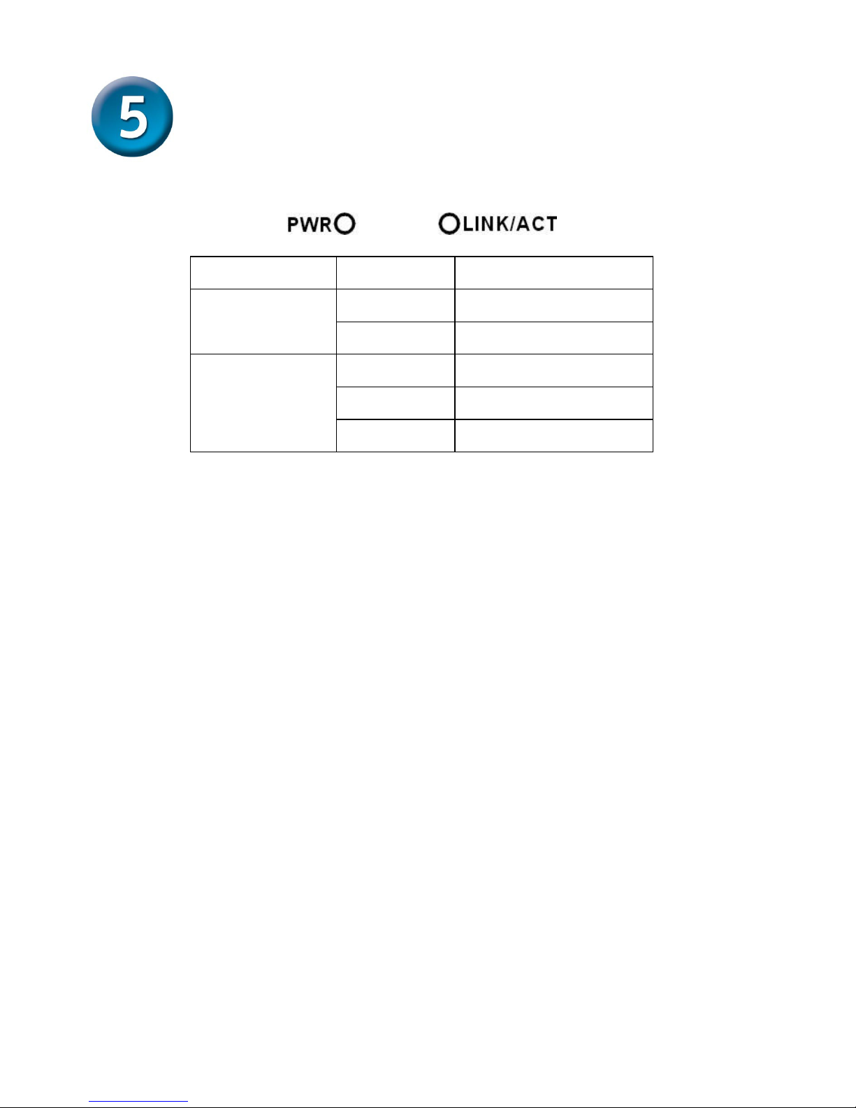
LED 指示燈
LED 指示燈會顯示設備目前的運作狀態:
LEDs 狀態 指示
燈亮 電源啟動
Power
(PWR)
燈滅 電源關閉
燈亮 連線
燈閃爍 資料傳輸與接收中
Link and Activity
(LINK/ACT)
燈滅 沒有連線
Page 35
35
Page 36
36
友冠技術支援
台灣地區用戶可以透過我們的網站,電子郵件或電話與
友冠資訊技術支援人員聯絡。
支援服務時間從
週一到週五,上午8:30 a.m. 到 7:00 p.m
Web: http://www.dlinktw.com.tw/
FAQ: http://www.dlinktw.com.tw/support.asp
Email: [email protected]
Phone: 0800-002-615
如果您是台灣地區以外的用戶,請參考使用手冊
中記載的D-Link 全球各地分公司的聯絡資訊
取得支援服務。
產品維修與保固相關資訊,請參考友冠資訊網頁說明:
http://www.dlinktw.com.tw/suppQuick.asp
 Loading...