

Page 1
1
Safety Instructions
2
3
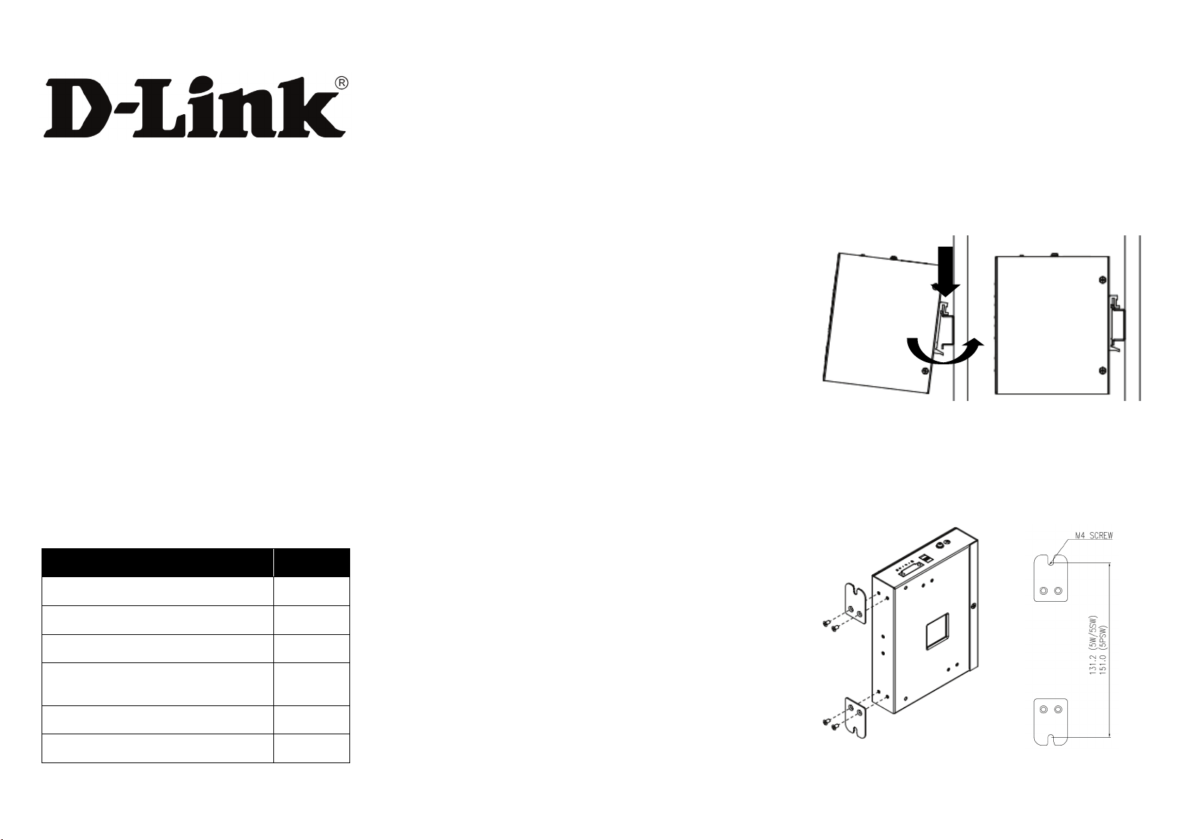
DIN-Rail Mounting
DIS-100G Series Unmanaged Industrial Gigabit Ethernet Switch
Quick Installation Guide
Overview
The DIS-100G unmanaged Industrial Gigabit Ethernet
Switch solutions are designed for supporting standard
industrial applications without complex setup to make the
network truly plug-and-pl a y.
If the equipment is used in a manner not specified by the
manufacturer, the protection provided by the equipment
may be impaired.
Package Checklist
Please verify that the box contains the following items:
When a connector is removed during installation, testing, or
servicing, or when an energized fiber is broken, a risk of
ocular exposure to optical energy that may be potentially
hazardous occurs, depending on the laser output power.
The primary hazards of exposure to laser radiation from an
optical-fiber communication system are:
Damage to the eye by accidental exposure to a beam
emitted by a laser source.
Damage to the eye from viewing a connector attached
to a broken fiber or an energized fiber.
Documentation Conventions
The following conventions are used in this quick installation
guide to emphasize information that will be of interest to the
reader.
Danger — The described activity or situation might or
will cause personal injury.
Warning — The described activity or situation might or
will cause equipment damage.
Caution — The described activity or situation might or
will cause service interruption.
Mounting step:
1. Screw the DIN-Rail bracket on with the bracket and
screws in the accessory kit.
2. Hook the unit over the DIN rail.
3. Push the bottom of the unit towards the DIN Rail until it
snaps into place.
Wall Mounting (unit: mm)
Mounting step:
1. Screw on the wall-mount plate on with the plate and
M4 screws in the accessory kit.
Item Quantity
Unmanaged switch 1
Wall-mount plates 2
DIN-Rail kit 1
M4 Screws
(for the wall mount plates & DIN Rail kit)
DC power terminal block 1
Quick Installation Guide 1
4
Note — The information supplements the text or
highlights important points.
Page 2
2
DIS-100G-5W
DIS-100G-5SW
DIS-100G-5PSW
DIS-100G-5W
DANGER:
that might be emitting laser energy.
NOTE:
well-fused power supply.
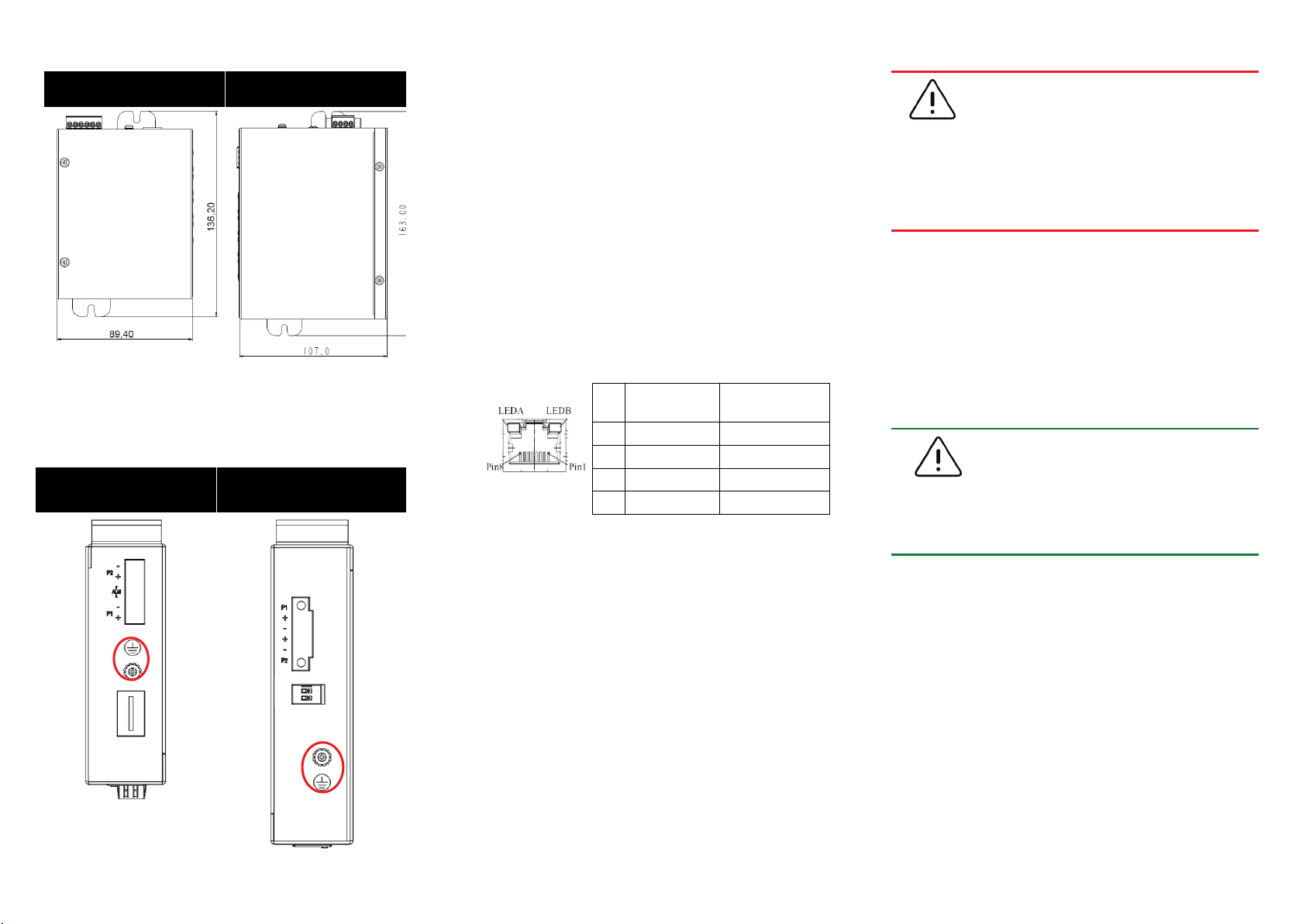
Ground Connecting
The switch must be properly grounded for optimum system
performance.
DIS-100G-5SW
DIS-100G-5PSW
Ethernet Interface Connecting (RJ45 Ethernet)
The switches provide two types of electrical (RJ45) and
optical (mini-GBIC) interfaces.
Connecting the Ethernet interface via RJ45:
To connect to a PC, use a straight-through or a
cross-over Ethernet cable,
To connect the switch to an Ethernet device, use UTP
(Unshielded Twisted Pair) or STP (Shielded Twisted
Pair) Ethernet cables.
The pin assignment of RJ-45 connector is shown in the
following figure and table.
Pin Assignment
1,2 T/Rx+,T/Rx- Positive V
3,6 T/Rx+,T/Rx- Negative V
4,5 T/Rx+,T/Rx- X
7,8 T/Rx+,T/Rx- X
PoE
Assignment
Port
Port
Ethernet Interface Connecting the (Fiber, SFP)
For a 1000 Mbps fiber port available, please use the
mini-GBIC SFP (small form pluggable). These accept plug
in fiber transceivers that typically have an LC style
connector. They are available with multimode, single mode,
long-haul (for connections up to 80+ km) or
special-application transceivers.
For each fiber port there is a transmit (TX) and receive (RX)
signal. Please make sure that the transmit (TX) port of the
switch connects to the receive (RX) port of the other device,
and the receive (RX) port of the switch connects to the
transmit (TX) port of the other device when making your
fiber optic connections.
Never attempt to view optical connectors
Do not power up the laser product without
connecting the laser to the optical fiber and
putting the cover in position, as laser
outputs will emit infrared laser light at this
point.
Power Connecting
The switch can be powered from two power supply (input
range 12V – 58V). Insert the positive and negative wires
(AW G 14-26) into V+ and V- contact on the terminal block
and tighten the wire-clamp screws to prevent the wires from
being loosened.
1. The DC power should be connected to a
2. Input power should be within the range
of 54~58VDC for PoE+ compliant, or
48-58VDC for PoE compliant.
Page 3
3
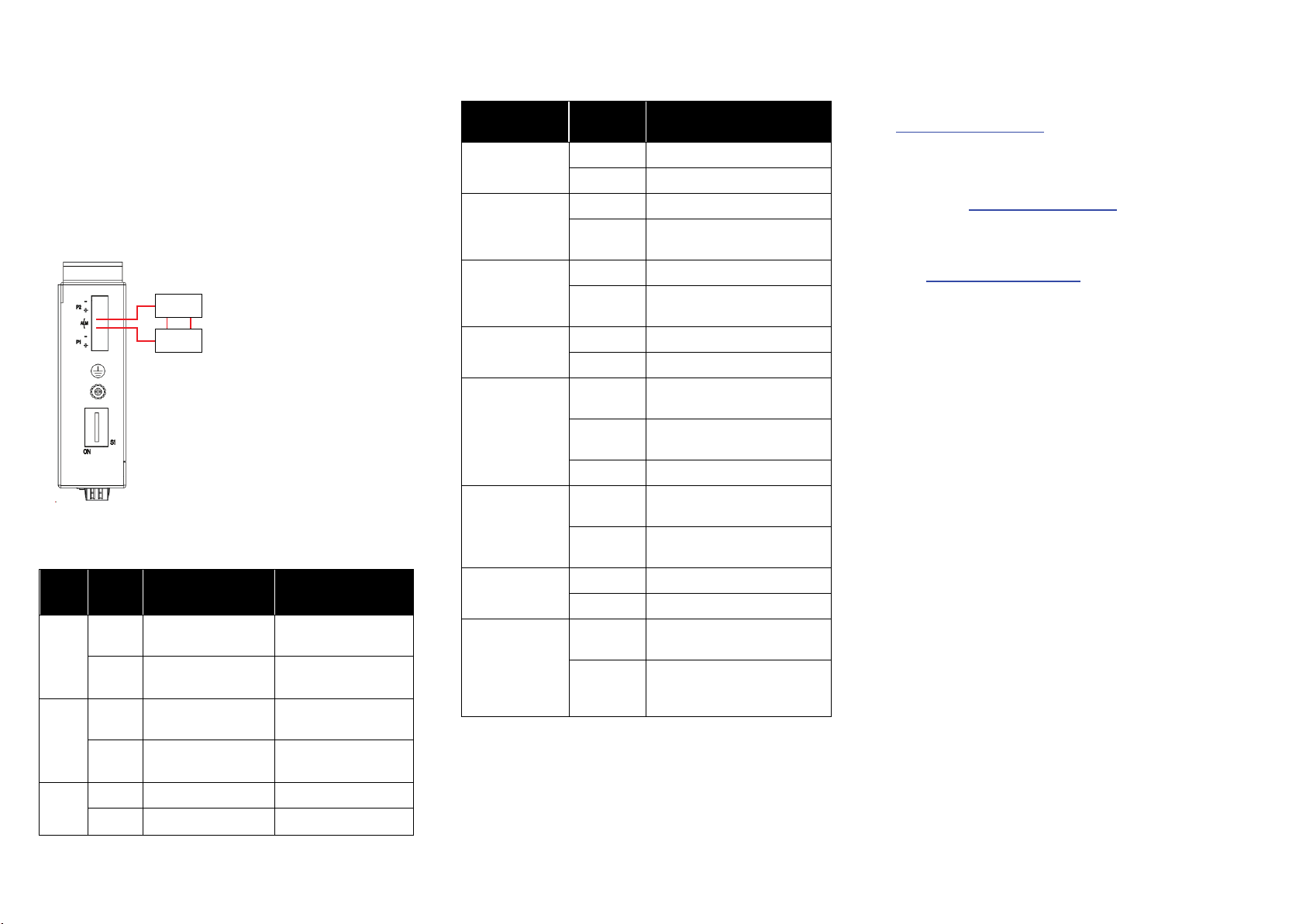
Alarm Relay Connecting (for Non-PoE Models)
Alarm
system
Extra power
system
Maximum 1A / DC 24V
LED STATUS INDICATIONS
Additional Information
The alarm relay output contacts are in the middle of the DC
terminal block connector shown as the figure belo w.
By inserting the wires and set the DIP switch of the
respective Port Alarm to “ON”, the relay output alarm will
detect any port failures, and form a short circuit.
The alarm relay out is “Normal Open”.
DIP Switch Setting
Pin
No#
Pin 1
Pin 2
Pin 3-6
Status
ON
OFF
ON
OFF
ON NOT USED NOT USED
OFF NOT USED NOT USED
DIS-100G-5S
DIS-100G-5SW
To enable the power
alarm.
To disable the power
alarm.
To enable Broadcast
storm rate limit
To disable Broadcast
storm rate limit
DIS-100G-5PSW
To enable Broadcast
storm rate limit.
To disable Broadcast
storm rate limit
NOT USED
NOT USED
LED Name Indicator/
PoE
P1
P2
ALM
Copper 1 to N
port Link/Act
Copper 1 to N
port Speed
SFP 1 to N port
(N=0,1,2)
Link/Act
SFP 1 to N port
(N=0,1,2) Speed
color
On Green PoE is working.
Off PoE is not working
On Green P1 power line has power
Off P1 power line disconnect or
On Green P2 power line has power
Off P2 power line disconnect or
On Red Power failure alarm occurs
Off No power failure alarm
On Green Ethernet link up but no traffic is
Blinking
Green
Off Ethernet link down
On Yellow A 1000Mbps connection is
Off No link, a 10Mbps or 100
On Green Ethernet link up
Off Ethernet link down
On Yellow SFP port speed 1000Mbps
Off No link or a SFP port speed
Condition
does not have supply power
does not have supply power
detected
Ethernet link up and there is
traffic detected
detected
Mbps connection is detected
connection is detected.
100Mbps connection is
detected
You can refer to the user manual or visit
http://support.dlink.com/
for more support.
Online Support
If there are any issues that are not in the user manual,
please visit http://support.dlink.com/
your appropriate local D-Link support website.
which will direct you to
Warranty Information
Visit http://warranty.dlink.com/ to view the D-Link Warranty
information.
Page 4

4
Regulatory Statements
Ver. 2.00(WW) 2018/11/08 GP800861X-000
Federal Communication Commission
Interference Statement
This equipment has been tested and found to comply with the
limits for a Class A digital device, pursuant to part 15 of the FCC
Rules. These limits are designed to provide reasonable protection
against harmful interference when the equipment is operated
in a commercial environment. This equipment generates, uses,
and can radiate radio frequency energy and, if not installed and
used in accordance with the instruction manual, may cause
harmful interference to radio communications. Operation of
this equipment in a residential area is likely to cause harmful
interference in which case the user will be required to correct the
interference at his own expense.
Non-modifcation Statement
Any changes or modifcations not expressly approved by the
party responsible for compliance could void the user's authority
to operate the equipment.
Caution
This device complies with Part 15 of the FCC Rules. Operation is
subject to the following two conditions:
(1) This device may not cause harmful interference, and (2)
this device must accept any interference received, including
interference that may cause undesired operation.
Industry Canada Statement:
This Class A digital apparatus complies with Canadian ICES-003.
Cet appareil numérique de la classe A est conforme à la norme
NMB-003 du Canada.
Japan Voluntary Control Council for Interference
Statement
この装置は、クラス A 情報技術装置です。 この装置を家
庭環境で使用すると電波妨害を引き起こすことがありま
す。 この場合には使用者が適切な対策を講ずるよう要求さ
れることがあります。 VCCI-A
Japan Voluntary Control Council for Interference
Statement
This is a Class A product based on the standard of the
Voluntary Control Council for Interference (VCCI). If this
equipment is used in a domestic environment, radio
interference may occur, in which case the user may be
required to take corrective actions.
警告使用者:
此為甲類的資訊技術設備,在居住環境中使用時,可能會
造成射頻擾動,在這種情況下,使用者會被要求採取某些
適當的對策。
Warning: This is a class A product. In a domestic environment this
product may cause radio interference in which case the user may
be required to take adequate measures.
CE EMI Class A Warning
This equipment is compliant with Class A of CISPR 32. In a
residential environment this equipment may cause radio
interference.
SAFETY INSTRUCTIONS
The following general safety guidelines are provided to help ensure
your own personal safety and protect your product from potential
damage. Remember to consult the product user instructions for
more details.
Static electricity can be harmful to electronic components.
Discharge static electricity from your body (i.e. touching grounded
bare metal) before touching the product.
Do not attempt to service the product and never disassemble the
product. For some products with user replaceable battery, please
read and follow the instructions in the user manual.
Do not spill food or liquid on your product and never push any
objects into the openings of your product.
Do not use this product near water, areas with high humidity or
condensation unless the product is specifcally rated for outdoor
application.
Keep the product away from radiators and other heat sources.
Always unplug the product from mains power before cleaning and
use a dry lint free cloth only
 Loading...