

Page 1

D-Link ™ DGS-3324SR
High-Density Layer 3 Stackable Gigabit Ethernet Switch
User’s Guide
Page 2

D-Link DGS-3324SR Stackable Gigabit Ethernet Switch
ii
____________________
Information in this document is subject to change without notice.
© 2004 D-Link Corporation. All rights reserved.
Reproduction in any manner whatsoever without the written permission of D-Link
Corporation is strictly forbidden.
Trademarks used in this text: D-Link, the D-LINK logo are trademarks of D-Link Computer Corporation; Microsoft and Windows are
registered trademarks of Microsoft Corporation.
Other trademarks and trade names may be used in this document to refer to either the entities claiming the marks and names or their products.
D-Link Computer Corporation disclaims any proprietary interest in trademarks and trade names other than its own.
February 2004 P/N 651GS3324025
Page 3

CONTENTS
D-Link ™ DGS-3324SR............................................................................................................ i
Intended Readers................................................................................................................................. ix
Typographical Conventions................................................................................................................ ix
Notes, Notices, and Cautions ................................................................................................... x
Safety Instructions.................................................................................................................... x
Safety Cautions ................................................................................................................................................x
General Precautions for Rack-Mountable Products ...................................................................................... xii
Protecting Against Electrostatic Discharge.................................................................................................. xiii
Introduction .............................................................................................................................. 1
Switch Description............................................................................................................................... 1
Features ............................................................................................................................................................1
Front-Panel Components ..................................................................................................................... 2
LED Indicators.................................................................................................................................................2
Rear Panel Description ........................................................................................................................ 2
RPS Connector .................................................................................................................................................3
Management Options........................................................................................................................... 3
Web-based Management Interface...................................................................................................................3
Command Line Console Interface Through the Serial Port or Telnet..............................................................3
SNMP-Based Management..............................................................................................................................3
Installation ................................................................................................................................ 3
Package Contents................................................................................................................................. 3
Switch Installation ............................................................................................................................... 4
Installing the Switch Without the Rack............................................................................................................4
Installing the Switch in a Rack.........................................................................................................................4
Connecting Stacked Switch Groups..................................................................................................... 5
Configuring a Switch Group for Stacking........................................................................................................7
Unit ID Display for Switches in a Switch Stack ..............................................................................................8
Gigabit Combo Ports ........................................................................................................................... 8
External Redundant Power System...................................................................................................... 9
Connecting the Console Port ............................................................................................................. 10
Password Protection........................................................................................................................... 11
SNMP Settings................................................................................................................................... 12
Traps ............................................................................................................................................................................12
MIBs ............................................................................................................................................................................12
IP Address Assignment...................................................................................................................... 13
Page 4

Connecting Devices to the Switch ..................................................................................................... 14
Introduction to Switch Management.................................................................................... 15
Introduction........................................................................................................................................ 15
Login to Web Manager ...................................................................................................................... 15
Web-based User Interface.................................................................................................................. 16
Areas of the User Interface.............................................................................................................................16
Web Pages......................................................................................................................................................17
Basic Setup ........................................................................................................................................ 18
Switch Information.........................................................................................................................................18
Switch IP Settings ..........................................................................................................................................18
Security IP Management Stations Configuration...........................................................................................21
User Accounts Management ..........................................................................................................................21
Admin and User Privileges...........................................................................................................................................22
Saving Changes..............................................................................................................................................22
Factory Reset..................................................................................................................................................23
Restart System................................................................................................................................................24
Switch Information ............................................................................................................................ 24
Advanced Settings ............................................................................................................................. 25
Configuration.......................................................................................................................... 28
Configuring Box Information ............................................................................................................ 28
Configuring Ports............................................................................................................................... 29
Configuring Port Mirroring ............................................................................................................... 30
Configuring Link Aggregation .......................................................................................................... 31
Understanding Port Trunk Groups .................................................................................................................31
LACP Port Setting ............................................................................................................................. 34
Configuring IGMP............................................................................................................................. 36
IGMP Snooping .............................................................................................................................................36
Static Router Ports..........................................................................................................................................37
Configuring The Spanning Tree ........................................................................................................ 39
802.1w Rapid Spanning Tree.........................................................................................................................39
Port Transition States ...................................................................................................................................................39
802.1d/802.1w Compatibility.......................................................................................................................................40
STP Switch Settings.......................................................................................................................................40
STP Port Settings ...........................................................................................................................................41
Configuring Forwarding & Filtering ................................................................................................. 43
Static Unicast Forwarding..............................................................................................................................43
Static Multicast Forwarding...........................................................................................................................44
Configuring VLANs .......................................................................................................................... 45
Page 5

Understanding IEEE 802.1p Priority..............................................................................................................45
VLANs ...........................................................................................................................................................46
Notes About VLANs on the DGS-3324SR ..................................................................................................................46
IEEE 802.1Q VLANs.....................................................................................................................................46
802.1Q VLAN Packet Forwarding...............................................................................................................................47
802.1Q VLAN Tags .....................................................................................................................................................47
Port VLAN ID..............................................................................................................................................................49
Tagging and Untagging................................................................................................................................................49
Ingress Filtering ...........................................................................................................................................................50
Default VLANs............................................................................................................................................................50
Port-based VLANs.........................................................................................................................................50
VLAN Segmentation....................................................................................................................................................51
VLAN and Trunk Groups.............................................................................................................................................51
Configuring Static VLANs.............................................................................................................................51
GVRP Settings ...............................................................................................................................................53
Configuring Traffic Control (Broadcast/Multicast Storm Control)................................................... 55
Configuring Port Security.................................................................................................................. 56
Configuring QoS................................................................................................................................ 58
Understanding QoS ........................................................................................................................................58
Setting Bandwidth Control.............................................................................................................................58
QoS Scheduling Mechanism Table ................................................................................................................60
QoS Output Scheduling..................................................................................................................................60
802.1p Default Priority...................................................................................................................................61
802.1p User Priority .......................................................................................................................................62
Configuring Traffic Segmentation .................................................................................................................63
The System Log Server...................................................................................................................... 64
Configuring SNTP Settings ............................................................................................................... 66
Time Settings .................................................................................................................................................66
Time Zone and DST.......................................................................................................................................68
Configuring The Access Profile Table .............................................................................................. 69
Configuring The Port Access Entity .................................................................................................. 77
802.1X Port-based Network Access Control..................................................................................................77
Configure Authenticator.................................................................................................................................79
Configuring Local Users ................................................................................................................................82
PAE System Control ......................................................................................................................................82
Port Capability Settings................................................................................................................................................82
Initializing Ports...........................................................................................................................................................84
Reauthenticate Port(s) ..................................................................................................................................................85
RADIUS Server .............................................................................................................................................86
Page 6

Configuring Layer 3 IP Networking.................................................................................................. 87
L3 Global Advanced Settings.........................................................................................................................87
Setting Up IP Interfaces .................................................................................................................................88
MD5 Key........................................................................................................................................................90
Route Redistribution Settings.........................................................................................................................90
Static/Default Route .......................................................................................................................................92
Static ARP Table............................................................................................................................................93
Routing Information Protocol (RIP)...............................................................................................................94
RIP Version 1 Message Format....................................................................................................................................95
RIP 1 Message..............................................................................................................................................................96
RIP 1 Route Interpretation ...........................................................................................................................................96
RIP Version 2 Extensions.............................................................................................................................................96
RIP2 Message Format..................................................................................................................................................96
Setting Up RIP .............................................................................................................................................................97
Configuring OSPF..........................................................................................................................................99
General OSPF Settings...............................................................................................................................................112
OSPF Area Setting.....................................................................................................................................................113
OSPF Interface Configuration....................................................................................................................................114
OSPF Virtual Interface Settings.................................................................................................................................116
Area Aggregation Configuration................................................................................................................................118
OSPF Host Route Settings .........................................................................................................................................119
DHCP/BOOTP Relay...................................................................................................................................120
DHCP/BOOTP Relay Information.............................................................................................................................120
DHCP/BOOTP Relay Settings...................................................................................................................................121
DNS Relay ...................................................................................................................................................121
Configuring DNS Relay Information .........................................................................................................................122
DNS Relay Static Table .............................................................................................................................................123
IP Multicasting .............................................................................................................................................123
IGMP Interface Configuration ...................................................................................................................................123
DVMRP Interface Configuration ...............................................................................................................................125
PIM_DM Interface Configuration..............................................................................................................................126
Managing SNMP .................................................................................................................. 129
SNMP Settings................................................................................................................................. 129
Traps ..........................................................................................................................................................................130
MIBs ..........................................................................................................................................................................130
SNMP User Table............................................................................................................................ 130
SNMP View Table........................................................................................................................... 132
SNMP Group Table ......................................................................................................................... 134
SNMP Community Table Configuration ......................................................................................... 136
SNMP Host Table............................................................................................................................ 137
Page 7

SNMP Engine ID ............................................................................................................................. 138
Monitoring ............................................................................................................................ 139
Port Utilization................................................................................................................................. 139
Packets ............................................................................................................................................. 140
Received(RX)...............................................................................................................................................141
UMB_cast(RX) ............................................................................................................................................143
Transmitted (TX) .........................................................................................................................................145
Errors ............................................................................................................................................... 147
Received (RX)..............................................................................................................................................147
Transmitted (TX) .........................................................................................................................................149
Size .................................................................................................................................................. 151
Stacking Information ....................................................................................................................... 153
Device Status ................................................................................................................................... 154
MAC Address .................................................................................................................................. 155
Switch History Log.......................................................................................................................... 156
IGMP Snooping Table ..................................................................................................................... 158
Browse Router Port.......................................................................................................................... 159
Port Access Control ......................................................................................................................... 159
Authenticator Statistics ................................................................................................................................159
Authenticator Session Statistics ...................................................................................................................161
Authenticator Diagnostics ............................................................................................................................162
Radius Authentication ..................................................................................................................................164
Radius Accounting .......................................................................................................................................166
Monitoring Layer 3 Features ........................................................................................................... 167
Browse IP Address.......................................................................................................................................167
Browse Routing Table..................................................................................................................................168
Browse ARP Table.......................................................................................................................................169
Browse IP Multicast Forwarding Table .......................................................................................................169
Browse IGMP Group Table .........................................................................................................................170
OSPF Monitoring.........................................................................................................................................170
OSPF LSDB Table.....................................................................................................................................................170
OSPF Neighbor Table ................................................................................................................................................171
OSPF Virtual Neighbor..............................................................................................................................................172
DVMRP Monitoring ....................................................................................................................................172
DVMRP Routing Table..............................................................................................................................................172
DVMRP Neighbor Address Table..............................................................................................................................173
DVMRP Routing Next Hop Table .............................................................................................................................173
PIM Monitoring ...........................................................................................................................................174
PIM Neighbor Address Table.....................................................................................................................................174
Page 8

Switch Maintenance ............................................................................................................. 175
TFTP Services.................................................................................................................................. 175
Download Firmware.....................................................................................................................................175
Download Configuration File.......................................................................................................................175
Upload Configuration...................................................................................................................................176
Upload Log...................................................................................................................................................176
Ping Test .......................................................................................................................................... 176
Save Changes................................................................................................................................... 177
Reset ................................................................................................................................................ 178
Reboot Device.................................................................................................................................. 179
Logout.............................................................................................................................................. 179
Technical Specifications....................................................................................................... 180
Glossary................................................................................................................................. 182
Page 9

D-Link DGS-3324SR Layer 3 Stackable Gigabit Ethernet Switch
ix
Intended Readers
The DGS-3324SR User Guide contains information for setup and management of the DGS-3324SR Switch. This
guide is intended for network managers familiar with network management concepts and terminology.
Typographical Conventions
Convention Description
[ ]
In a command line, square brackets indicate an optional entry. For
example: [copy filename] means that optionally you can type copy
followed by the name of the file. Do not type the brackets.
Bold font
Indicates a button, a toolbar icon, menu, or menu item. For example:
Open the File menu and choose Cancel. Used for emphasis. May
also indicate system messages or prompts appearing on your
screen. For example: You have mail. Bold font is also used to
represent filenames, program names and commands. For example:
use the copy command.
Boldface Typewriter
Font
Indicates commands and responses to prompts that must be typed
exactly as printed in the manual.
Initial capital letter
Indicates a window name. Names of keys on the keyboard have
initial capitals. For example: Click Enter.
Italics
Indicates a window name or a field. Also can indicate a variables or
parameter that is replaced with an appropriate word or string. For
example: type filename means that you should type the actual
filename instead of the word shown in italic.
Menu Name > Menu Option
Menu Name > Menu Option Indicates the menu structure.
Device > Port > Port Properties means the Port Properties menu
option under the Port menu option that is located under the Device
menu.
Page 10
D-Link DGS-3324SR Layer 3 Stackable Gigabit Ethernet Switch
x
Notes, Notices, and Cautions
Safety Instructions
Use the following safety guidelines to ensure your own personal safety and to help protect your system from
potential damage. Throughout this safety section, the caution icon ( ) is used to indicate cautions and
precautions that you need to review and follow.
Safety Cautions
To reduce the risk of bodily injury, electrical shock, fire, and damage to the equipment, observe the following
precautions.
Observe and follow service markings. Do not service any product except as explained in your system
documentation. Opening or removing covers that are marked with the triangular symbol with a lightning bolt
may expose you to electrical shock. Components inside these compartments should be serviced only by a trained
service technician.
If any of the following conditions occur, unplug the product from the electrical outlet and replace the part or
contact your trained service provider:
– The power cable, extension cable, or plug is damaged.
– An object has fallen into the product.
– The product has been exposed to water.
– The product has been dropped or damaged.
– The product does not operate correctly when you follow the operating instructions.
• Keep your system away from radiators and heat sources. Also, do not block cooling vents.
• Do not spill food or liquids on your system components, and never operate the product in a wet
environment. If the system gets wet, see the appropriate section in your troubleshooting guide or contact
your trained service provider.
NOTE: A NOTE indicates important information that helps you make
better use of your device.
NOTICE: A NOTICE indicates either potential damage to hardware or loss
of data and tells you how to avoid the problem.
CAUTION: A CAUTION indicates a potential for property damage,
personal injury, or death.
Page 11

D-Link DGS-3324SR Layer 3 Stackable Gigabit Ethernet Switch
xi
• Do not push any objects into the openings of your system. Doing so can cause fire or electric shock by
shorting out interior components.
• Use the product only with approved equipment.
• Allow the product to cool before removing covers or touching internal components.
• Operate the product only from the type of external power source indicated on the electrical ratings label.
If you are not sure of the type of power source required, consult your service provider or local power
company.
• To help avoid damaging your system, be sure the voltage selection switch (if provided) on the power
supply is set to match the power available at your location:
– 115 volts (V)/60 hertz (Hz) in most of North and South America and some Far Eastern countries such
as South Korea and Taiwan
– 100 V/50 Hz in eastern Japan and 100 V/60 Hz in western Japan
– 230 V/50 Hz in most of Europe, the Middle East, and the Far East
• Also be sure that attached devices are electrically rated to operate with the power available in your
location.
• Use only approved power cable(s). If you have not been provided with a power cable for your system or
for any AC-powered option intended for your system, purchase a power cable that is approved for use in
your country. The power cable must be rated for the product and for the voltage and current marked on
the product's electrical ratings label. The voltage and current rating of the cable should be greater than
the ratings marked on the product.
• To help prevent electric shock, plug the system and peripheral power cables into properly grounded
electrical outlets. These cables are equipped with three-prong plugs to help ensure proper grounding. Do
not use adapter plugs or remove the grounding prong from a cable. If you must use an extension cable,
use a 3-wire cable with properly grounded plugs.
• Observe extension cable and power strip ratings. Make sure that the total ampere rating of all products
plugged into the extension cable or power strip does not exceed 80 percent of the ampere ratings limit
for the extension cable or power strip.
• To help protect your system from sudden, transient increases and decreases in electrical power, use a
surge suppressor, line conditioner, or uninterruptible power supply (UPS).
• Position system cables and power cables carefully; route cables so that they cannot be stepped on or
tripped over. Be sure that nothing rests on any cables.
• Do not modify power cables or plugs. Consult a licensed electrician or your power company for site
modifications. Always follow your local/national wiring rules.
• When connecting or disconnecting power to hot-pluggable power supplies, if offered with your system,
observe the following guidelines:
– Install the power supply before connecting the power cable to the power supply.
– Unplug the power cable before removing the power supply.
– If the system has multiple sources of power, disconnect power from the system by
unplugging all power cables from the power supplies.
• Move products with care; ensure that all casters and/or stabilizers are firmly connected to the system.
Avoid sudden stops and uneven surfaces.
Page 12
D-Link DGS-3324SR Layer 3 Stackable Gigabit Ethernet Switch
xii
General Precautions for Rack-Mountable Products
Observe the following precautions for rack stability and safety. Also refer to the rack installation documentation
accompanying the system and the rack for specific caution statements and procedures.
Systems are considered to be components in a rack. Thus, "component" refers to any system as well as to various
peripherals or supporting hardware.
CAUTION: Installing systems in a rack without the front and side stabilizers
installed could cause the rack to tip over, potentially resulting in bodily injury under
certain circumstances. Therefore, always install the stabilizers before installing
components in the rack.
After installing system/components in a rack, never pull more than one component
out of the rack on its slide assemblies at one time. The weight of more than one
extended component could cause the rack to tip over and may result in serious
injury.
• Before working on the rack, make sure that the stabilizers are secured to the rack, extended to the floor,
and that the full weight of the rack rests on the floor. Install front and side stabilizers on a single rack or
front stabilizers for joined multiple racks before working on the rack.
Safety Instructions (continued)
Always load the rack from the bottom up, and load the heaviest item in the rack first.
Make sure that the rack is level and stable before extending a component from the rack.
Use caution when pressing the component rail release latches and sliding a component into or out of a rack; the
slide rails can pinch your fingers.
After a component is inserted into the rack, carefully extend the rail into a locking position, and then slide the
component into the rack.
Do not overload the AC supply branch circuit that provides power to the rack. The total rack load should not
exceed 80 percent of the branch circuit rating.
Ensure that proper airflow is provided to components in the rack.
Do not step on or stand on any component when servicing other components in a rack.
NOTE: A qualified electrician must perform all connections to DC power and to
safety grounds. All electrical wiring must comply with applicable local or national
codes and practices.
CAUTION: Never defeat the ground conductor or operate the equipment in the
absence of a suitably installed ground conductor. Contact the appropriate electrical
inspection authority or an electrician if you are uncertain that suitable grounding is
available.
Page 13

D-Link DGS-3324SR Layer 3 Stackable Gigabit Ethernet Switch
xiii
Protecting Against Electrostatic Discharge
Static electricity can harm delicate components inside your system. To prevent static damage, discharge static
electricity from your body before you touch any of the electronic components, such as the microprocessor. You
can do so by periodically touching an unpainted metal surface on the chassis.
You can also take the following steps to prevent damage from electrostatic discharge (ESD):
1. When unpacking a static-sensitive component from its shipping carton, do not remove the component
from the antistatic packing material until you are ready to install the component in your system. Just
before unwrapping the antistatic packaging, be sure to discharge static electricity from your body.
2. When transporting a sensitive component, first place it in an antistatic container or packaging.
3. Handle all sensitive components in a static-safe area. If possible, use antistatic floor pads and
workbench pads and an antistatic grounding strap.
CAUTION: The system chassis must be positively grounded to the rack cabinet
frame. Do not attempt to connect power to the system until grounding cables are
connected. Completed power and safety ground wiring must be inspected by a
qualified electrical inspector. An energy hazard will exist if the safety ground cable
is omitted or disconnected.
Page 14

D-Link DGS-3324SR Layer 3 Stackable Gigabit Ethernet Switch
1
Section 1
Introduction
Switch Description
Features
Front-Panel Components
Back Panel Description
Plug-in Module Descriptions
Management Options
Switch Description
The DGS-3324SR is a modular Gigabit Ethernet backbone switch designed for adaptability and scalability. The
Switch provides a management platform and uplink to backbone for a stacked group of twelve DGS-3324SR
Layer 3 switches in a ring or chain topology arrangement. Alternatively, the Switch can utilize up to twenty-four
Gigabit Ethernet ports to function as a central distribution hub for other switches or switch groups, or routers.
The four built-in combination Gigabit ports have the option of being used as either 1000BASE-T or SFP Gigabit
connections.
Features
• 4 built-in combination 1000BASE-T/SFP ports
• Ring or chain topology switch stacking configuration for up to 12 additional DGS-3324SR switches
• 88 Gbps switching fabric capacity
• Supports 802.1D STP and 802.1w Rapid Spanning Tree for redundant back up bridge paths
• Supports 802.1Q VLAN, IGMP snooping, 802.1p Priority Queues, port trunking, port mirroring
• Multi-layer Access Control (based on MAC address, IP address, VLAN, Protocol, 802.1p, DSCP)
• Supports Layer 3 functions including multiple IP Interfaces, MD5 Key Configuration, Route
Redistribution, Static and Default Route settings, Static ARP settings, RIP, OSPF, DNS Relay and IP
Multicast Routing Protocol.
• Quality of Service (QoS) customized control
• 802.1x (port-based) access control and RADIUS Client support
• Administrator-definable port security
• Per-port bandwidth control
• IEEE 802.3z and IEEE 802.3x compliant Flow Control for all Gigabit ports
• SNMP v.1, v.2, v.3 network management, RMON support
• Support optional external Redundant Power Supply
• Supports Web-based management.
• CLI management support
• DHCP and BOOTP Client support.
• Fully configurable either in-band or out-of-band control via RS-232 console serial connection.
• Telnet remote control console
Page 15
D-Link DGS-3324SR Layer 3 Stackable Gigabit Ethernet Switch
2
• TFTP upgrade
• Traffic Segmentation
• SysLog support
• Simple Network Time Protocol
• Web GUI Traffic Monitoring
Front-Panel Components
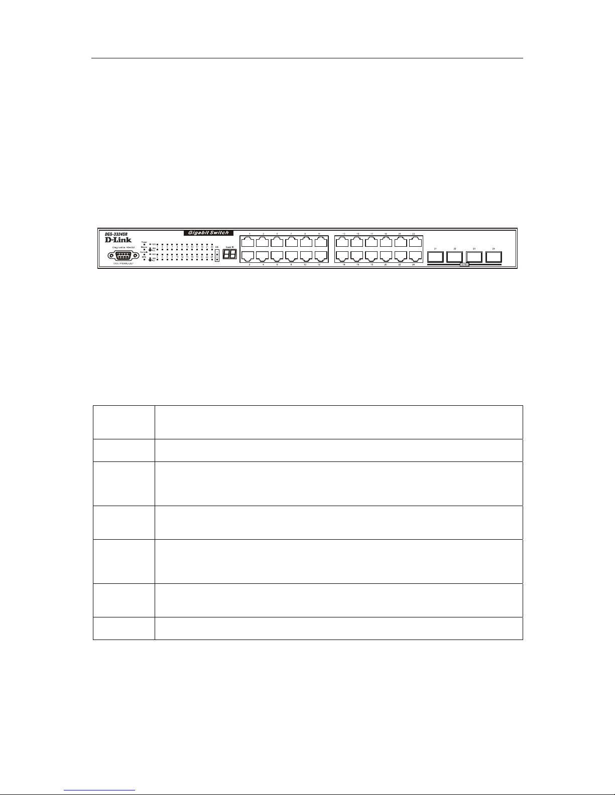
The front panel of the Switch consists of LED indicators, an RS-232 communication port, and four SFP (MiniGBIC) combo ports.
Figure 1 - 1. Front Panel View of the switch
Comprehensive LED indicators display the status of the Switch and the network.
An RS-232 DCE console port for setting up and managing the Switch via a connection to a console terminal or
PC using a terminal emulation program.
LED Indicators
The LED indicators of the Switch include Power, Master, Console, RPS (Redundant Power Supply), 1000
Link/Act, Stack ID and SIO. A bank of 24 LEDs (2 for each port) indicates link, activity status and connection
speed for each port
Power
It will light green approximately 2 seconds after the switch is powered on to indicate
the ready state of the device.
Master
Lights steady green when the Switch is configured as the Master Switch in a stack.
Console
This indicator on the front panel should be lit during the Power-On Self Test (POST).
Lights green when the switch is being managed via out-of-band/local console
management through the RS-232 console port using a straight-through serial cable.
RPS
This indicator will light steady amber when an external power supply is supplying
power. This indicates the internal power supply has failed.
1000
Link/Act
Each on-board Gigabit Ethernet port has a corresponding indicator. This will light
steady green for a valid link and blink whenever there is reception or transmission
(i.e. Activity--Act) of data occurring at a port.
Stack ID
The switch includes a 7-segment LED (labeled STACK ID) to indicate the switch
status in a stacked switch group.
SIO
Indicates which stacking port, if any, is in use.
Rear Panel Description
The rear panel of the Switch contains an AC power connector, a connector for the Redundant Power Supply
(RPS) and two stacking ports.
Page 16

D-Link DGS-3324SR Layer 3 Stackable Gigabit Ethernet Switch
3
Figure 1-2. Rear panel view of the Switch
The AC power connector is a standard three-pronged connector that supports the power cord. Plug the female
connector of the provided power cord into this socket, and the male side of the cord into a power outlet. The
Switch automatically adjusts its power setting to any supply voltage in the range from 100 ~ 240 VAC at 50 ~ 60
Hz.
RPS Connector
Connect the optional external redundant power supply to the RPS connector. If the Switch’s internal power unit
fails, the redundant power system automatically supplies power to the switch for uninterrupted operation.
The switch supports the D-Link RPS-500 redundant power supply units.
Management Options
The system may be managed out-of-band through the console port on the front panel or in-band using Telnet or a
web browser.
Web-based Management Interface
After you have successfully installed the Switch, you can configure the Switch, monitor the LED panel, and
display statistics graphically using a web browser, such as Netscape Navigator (version 6.2 and higher) or
Microsoft
® Internet Explorer (version 5.0).
NOTE: To access the Switch through a web browser, the computer
running the web browser must have IP-based network access to the
switch.
Command Line Console Interface Through the Serial Port or Telnet
You can also connect a computer or terminal to the serial console port or use Telnet to access the Switch. The
command-line-driven interface provides complete access to all switch management features. For a full list of
commands, see the Command Line Interface Reference Manual, which is included on the documentation CD.
SNMP-Based Management
You can manage the Switch with an SNMP-compatible console program. The Switch is supports SNMP version
1.0, version 2.0 and version 3.0. The SNMP agent decodes the incoming SNMP messages and responds to
requests with MIB objects stored in the database. The SNMP agent updates the MIB objects to generate statistics
and counters.
The Switch supports a comprehensive set of MIB extensions:
• RFC1213 MIB II
• RFC1493 Bridge
• RFC1643 Ether-like MIB
• RFC1724 RIP 2
• RFC1757 RMON
• RFC1850 OSPF Version 2
Page 17

D-Link DGS-3324SR Layer 3 Stackable Gigabit Ethernet Switch
2
• RFC1907 (SNMPv2-MIB)
• RFC2021 (RMON2)
• RFC2096 IP Forwarding
• RFC2233 Interface MIB
• RFC2571 (SNMP Frameworks)
• RFC2572 (Message Processing for SNMP)
• RFC2573 (SNMP Applications)
• RFC2574 (USM for SNMP)
• RFC2575 (VACM for SNMP)
• RFC2576 (Coexistence between SNMPs)
• RFC2618 (Radius-Auth-Client-MIB)
• RFC2620 (Radius-Acc-Client-MIB)
• RFC2932 IPv4 Multicast Routing
• RFC2933 IGMP
• RFC2934 PIM
• DVMRP MIB
• D-Link Enterprise MIB
• 802.1p RFC2674
• IEEE8021-PAE-MIB
• RSTP-MIB
Page 18

D-Link DGS-3324SR Layer 3 Stackable Gigabit Ethernet Switch
3
Section 2
Installation
Package Contents
Before You Connect to the Network
Switch Installation
Connecting Stacked Switch Groups
Gigabit Combo Ports
External Redundant Power System
Connecting the Console Port
Password Protection
SNMP Settings
IP Address Assignment
Connecting Devices to the Switch
Package Contents
Before you begin installing the Switch, confirm that your package contains the following items:
• One DGS-3324SR Layer 3 Gigabit Switch
• Mounting kit: 2 mounting brackets and screws
• Four rubber feet with adhesive backing
• One AC power cord
• This User’s Guide with Registration Card
• CLI Reference
• CD-ROM with User’s Guide and CLI Reference
Before You Connect to the Network
NOTICE: Do not connect the Switch to the network until you have established the
correct IP settings.
Before you connect to the network, you must install the Switch on a flat surface or in a rack, set up a terminal
emulation program, plug in the power cord, and then set up a password and IP address.
The Switch is supplied with rubber feet for stationing it on a flat surface and mounting brackets and screws for
mounting the Switch in a rack.
NOTICE: Do not connect the stacked switch group to the network until you have
properly configured all switches for switch stacking. An improperly configured
switch stack can cause a broadcast storm.
Page 19
D-Link DGS-3324SR Layer 3 Stackable Gigabit Ethernet Switch
4
Switch Installation
Installing the Switch Without the Rack
1. Install the Switch on a level surface that can safely support the weight of the Switch and its attached
cables. The Switch must have adequate space for ventilation and for accessing cable connectors.
2. Set the Switch on a flat surface and check for proper ventilation. Allow at least 5 cm (2 inches) on each
side of the Switch and 15 cm (6 inches) at the back for the power cable.
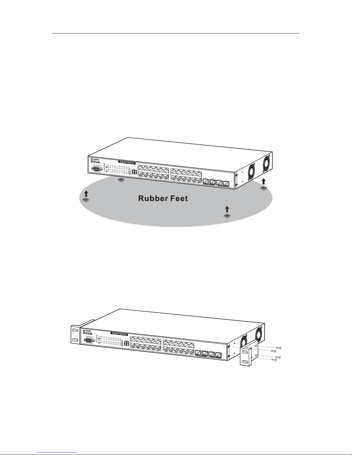
3. Attach the rubber feet on the marked locations on the bottom of the chassis.
4. The rubber feet, although optional, are recommended to keep the unit from slipping.
Figure 2-1. Install rubber feet for installations with or without a rack
Installing the Switch in a Rack
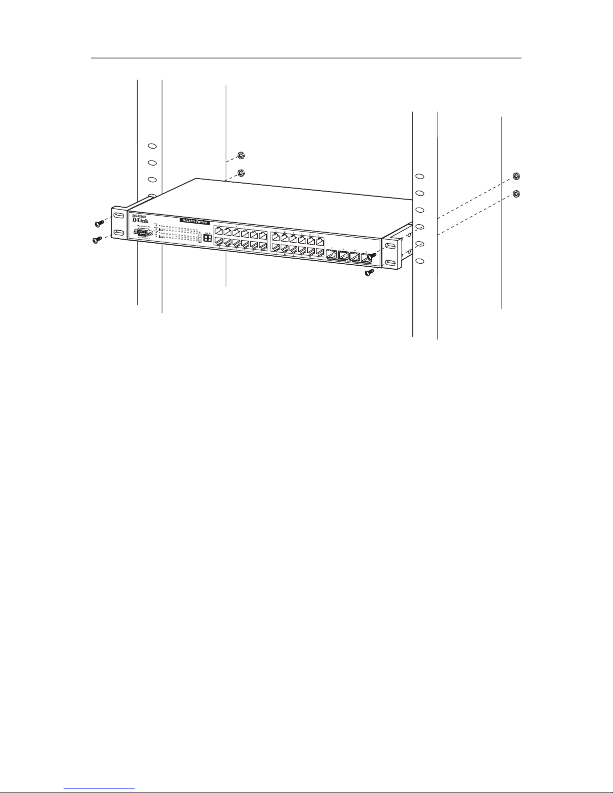
You can install the Switch in most standard 19-inch (48.3-cm) racks. Refer to the illustrations below.
1. Use the supplied screws to attach a mounting bracket to each side of the Switch.
2. Align the holes in the mounting bracket with the holes in the rack.
3. Insert and tighten two screws through each of the mounting brackets.
Figure 2-2. Attach mounting brackets
Page 20
D-Link DGS-3324SR Layer 3 Stackable Gigabit Ethernet Switch
5
Figure 2-3. Install switch in equipment rack
Connecting Stacked Switch Groups
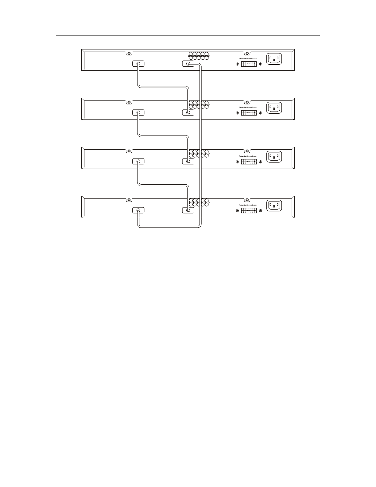
Up to 12 switches can be stacked together for Ring mode or Chain mode to a Master Unit or in tandem with a
second master unit via the second 10Gig stacking port. Users can add unit to reach maximum 288 GbE ports per
Ring stack or 168 GbE ports per Star stack. Switches are stacked together through a high-speed stack cables that
provide high speed of multiple Gigabit connections, allowing the entire stack to perform as a single IP entity.
User can see the number of switches stacked together from 7-segment display on front panel. Please refer to the
diagram below.
Page 21
D-Link DGS-3324SR Layer 3 Stackable Gigabit Ethernet Switch
6
Figure 2-4. Ring (Bus) Topology
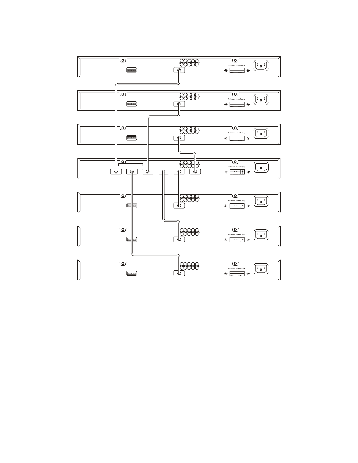
Please note that the DGS-3324SRi is needed to connect a group of Switches in the Star topology, as shown
below.
Page 22
D-Link DGS-3324SR Layer 3 Stackable Gigabit Ethernet Switch
7
Figure 2-5. Star Topology Stacked Switch Group
The stacking ports are designated 1 and 2, and the stacking port being used will have its matching LED (on the
front panel) light a steady green when in use. Connection can be made from any stacking port to any other
stacking port. That is, stacking port 1 may connect to 1 or 2, and stacking port 2 may connect to 2 or 1
Configuring a Switch Group for Stacking
Follow the instructions below to configure the DGS-3324SR as the designated Master, and then to configure the
slave units.
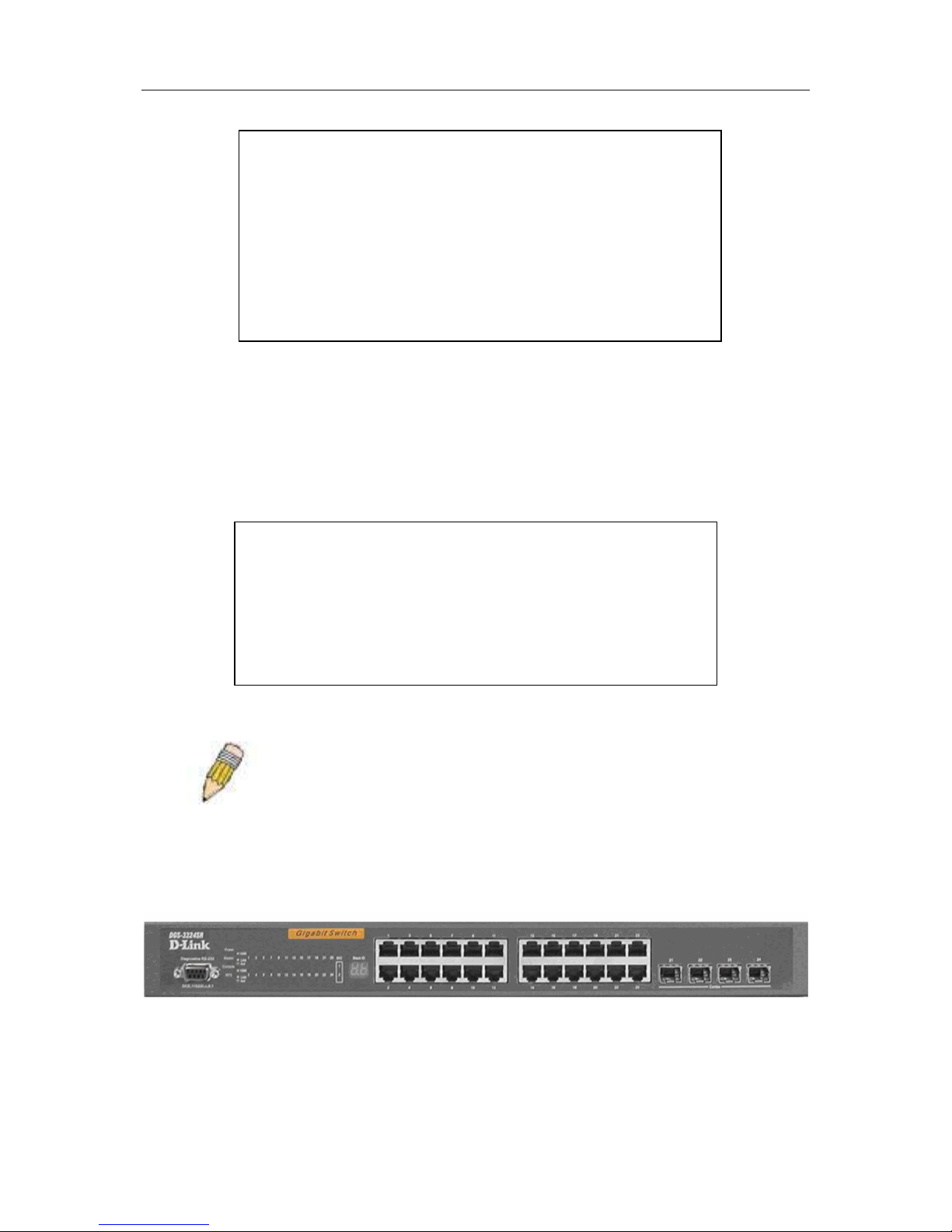
To configure the DGS-3324SR to function in a stacked group as a master, do the following:
1. At the CLI login prompt, enter config box_priority current_box_id 1 priority 1
and press the Enter key. (Where the lowest priority number in a stack is always the Master, i.e. 2 would
have a higher priority than 5.)
2. Successful configuration will be verified by a Success message. It takes a few seconds for the change to
take effect. See the example below for the DGS-3324SR.
3. Be sure to save the configuration change using the CLI command save.
4. Reboot the Switch.
Page 23
D-Link DGS-3324SR Layer 3 Stackable Gigabit Ethernet Switch
8
To configure the same DGS-3324SR to function in a stacked group as the Slave, do the following:
1. At the CLI login prompt, enter config box_priority current_box_id 1 priority 2
and press the Enter key.
2. Successful configuration will be verified by a Success message. It takes a few seconds for the change to
take effect. See the example below for the DGS-3324SR.
3. Be sure to save the configuration change using the CLI command save.
NOTE: Make sure that each box has a different ID. No two boxes can
have the same ID.
Unit ID Display for Switches in a Switch Stack
The Stack ID. 7-segment LED (as shown below) on the front panel displays the Stack ID of the Switch. Please
also note that the Master LED is lit, indicating that this Switch is the Master unit in the stack.
Gigabit Combo Ports
In addition to the 24 10/100/1000 Mbps ports, the Switch features four Mini-GBIC Combo ports. These four
ports are 10/100/1000BASE-T copper ports (built-in) and Mini-GBIC ports (optional). Please note that the MiniGBIC ports are used instead of the built-in 10/100/1000BASE-T ports. The Mini-GBIC ports will not work
DGS-3324SR:4#config box_priority current_box_id 1 priority 1
Command: config box_priority current_box_id 1 priority 1
Success.
DGS-3324SR:4#............
DGS-3324SR:4#
DGS-3324SR:4#config box_priority current_box_id 1 priority 2
Command: config config box_priority current_box_id 1 priority 2
Success.
DGS-3324SR:4#...................................................................
Page 24
D-Link DGS-3324SR Layer 3 Stackable Gigabit Ethernet Switch
9
simultaneously with its corresponding 10/100/1000BASE-T port. For example, if port 24x is used on the Mini
GBIC module, port 24 is not available for the 10/100/1000BASE-T built-in port, and vice versa.
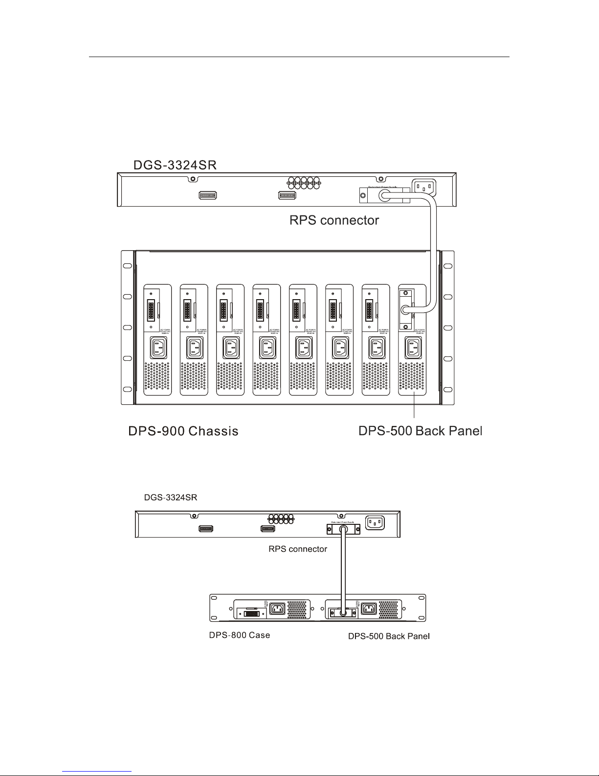
External Redundant Power System
The Switch supports an external redundant power system.
Figure 2-6. DPS-900 with DGS-3324SR
Figure 2-7. DPS-800 with DGS-3324SR
Page 25

D-Link DGS-3324SR Layer 3 Stackable Gigabit Ethernet Switch
10
NOTE: See the DPS-900 documentation for more information.
CAUTION: Do not use the Switch with any redundant power system other
than the DPS-900.
Connecting the Console Port
The Switch provides an RS-232 serial port that enables a connection to a computer or terminal for monitoring
and configuring the switch. This port is a DB-9 connector, implemented as a DCE connection.
To use the console port, you need the following equipment:
• A terminal or a computer with both a serial port and the ability to emulate a terminal
• A RS-232 cable with a female DB-9 connector for the console port on the switch
To connect a terminal to the console port:
1. Connect the RS-232 cable directly to the console port on the Switch, and tighten the captive retaining
screws.
2. Connect the other end of the cable to a terminal or to the serial connector of a computer running
terminal emulation software. Set the terminal emulation software as follows:
1. Select the appropriate serial port (COM port 1 or COM port 2).
3. Set the data rate to 115200 baud.
4. Set the data format to 8 data bits, 1 stop bit, and no parity.
5. Set flow control to
none.
6. Under Properties, select VT100 for Emulation mode.
7. Select Terminal keys for Function, Arrow, and Ctrl keys. Ensure that you select Terminal
keys (not Windows keys).
NOTICE: When you use HyperTerminal with the Microsoft® Windows® 2000
operating system, ensure that you have Windows 2000 Service Pack 2 or later
installed. Windows 2000 Service Pack 2 allows you to use arrow keys in
HyperTerminal’s VT100 emulation. See www.microsoft.com for information on
Windows 2000 service packs.
8. After you have correctly set up the terminal, plug the power cable into the power receptacle on
the back of the Switch. The boot sequence appears in the terminal.
9. After the boot sequence completes, the console login screen displays.
10. If you have not logged into the command line interface (CLI) program, press the Enter key at
the User name and password prompts. There is no default user name and password for the
Switch, user names and passwords must first be created by the administrator. If you have
previously set up user accounts, log in and continue to configure the Switch.
11. Enter the commands to complete your desired tasks. Many commands require administratorlevel access privileges. Read the next section for more information on setting up user accounts.
See the Command Line Reference on the documentation CD for a list of all commands and
additional information on using the CLI.
Page 26

D-Link DGS-3324SR Layer 3 Stackable Gigabit Ethernet Switch
11
12. When you have completed your tasks, exit the session with the logout command or close the
emulator program.
Password Protection
The DGS-3324SR does not have a default user name and password. One of the first tasks when settings up the
Switch is to create user accounts. If you log in using a predefined administrator-level user name you have
privileged access to the Switch’s management software.
After your initial login, define new passwords for both default user names to prevent unauthorized access to the
Switch, and record the passwords for future reference.
To create an administrator-level account for the Switch, do the following:
1. At the CLI login prompt, enter create account admin followed by the <user name> and press
the Enter key.
2. You will be asked to provide a password. Type the <password> used for the administrator
account being created and press the Enter key.
3. You will be prompted to enter the same password again to verify it. Type the same password
and press the Enter key.
4. Successful creation of the new administrator account will be verified by a Success message.
User names and passwords can be up to 15 characters in length.
The sample below illustrates a successful creation of a new
administrator-level account with the user name “newmanager”.
NOTE: Passwords
are case sensitive.
NOTICE: CLI configuration commands only modify the running
configuration file and are not saved when the Switch is rebooted. To save
all your configuration changes in nonvolatile storage, you must use the
save command to copy the running configuration file to the startup
configuration.
DGS-3324SR:4#create account admin newmanager
Command: create account admin newmanager
Enter a case-sensitive new password:********
Enter the new password again for confirmation:********
Success.
DGS-3324SR:4#
Page 27

D-Link DGS-3324SR Layer 3 Stackable Gigabit Ethernet Switch
12
SNMP Settings
Simple Network Management Protocol (SNMP) is an OSI Layer 7 (Application Layer) function designed
specifically for managing and monitoring network devices. SNMP enables network management stations to read
and modify the settings of gateways, routers, switches, and other network devices. Use SNMP to configure
system features for proper operation, monitor performance and detect potential problems in the Switch, switch
group or network.
Managed devices that support SNMP include software (referred to as an agent), which runs locally on the device.
A defined set of variables (managed objects) is maintained by the SNMP agent and used to manage the device.
These objects are defined in a Management Information Base (MIB), which provides a standard presentation of
the information controlled by the on-board SNMP agent. SNMP defines both the format of the MIB
specifications and the protocol used to access this information over the network.
The DGS-3324SR supports the SNMP versions 1, 2c, and 3. You can specify which version of the SNMP you
want to use to monitor and control the Switch. The three versions of SNMP vary in the level of security
provided between the management station and the network device.
In SNMP v.1 and v.2, user authentication is accomplished using ‘community strings’, which function like
passwords. The remote user SNMP application and the switch SNMP must use the same community string.
SNMP packets from any station that has not been authenticated are ignored (dropped).
The default community strings for the Switch used for SNMP v.1 and v.2 management access are:
public - Allows authorized management stations to retrieve MIB objects.
private - Allows authorized management stations to retrieve and modify MIB objects.
SNMP v.3 uses a more sophisticated authentication process that is separated into two parts. The first part is to
maintain a list of users and their attributes that are allowed to act as SNMP managers. The second part describes
what each user on that list can do as an SNMP manager.
The Switch allows groups of users to be listed and configured with a shared set of privileges. The SNMP version
may also be set for a listed group of SNMP managers. Thus, you may create a group of SNMP managers that are
allowed to view read-only information or receive traps using SNMP v.1 while assigning a higher level of
security to another group, granting read/write privileges using SNMP v.3.
Using SNMP v.3 individual users or groups of SNMP managers can be allowed to perform or be restricted from
performing specific SNMP management functions. The functions allowed or restricted are defined using the
Object Identifier (OID) associated with a specific MIB. An additional layer of security is available for SNMP v.3
in that SNMP messages may be encrypted. To read more about how to configure SNMP v.3 settings for the
Switch read the next section.
Traps
Traps are messages that alert network personnel of events that occur on the Switch. The events can be as serious
as a reboot (someone accidentally turned OFF the Switch), or less serious like a port status change. The Switch
generates traps and sends them to the trap recipient (or network manager). Typical traps include trap messages
for Authentication Failure, Topology Change and Broadcast\Multicast Storm.
MIBs
Management and counter information are stored by the switch in the Management Information Base (MIB). The
Switch uses the standard MIB-II Management Information Base module. Consequently, values for MIB objects
can be retrieved from any SNMP-based network management software. In addition to the standard MIB-II, the
Switch also supports its own proprietary enterprise MIB as an extended Management Information Base. The
proprietary MIB may also be retrieved by specifying the MIB Object Identifier. MIB values can be either readonly or read-write.
Page 28
D-Link DGS-3324SR Layer 3 Stackable Gigabit Ethernet Switch
13
IP Address Assignment
Each switch must be assigned its own IP Address, which is used for communication with an SNMP network
manager or other TCP/IP application (for example BOOTP, TFTP). The Switch’s default IP address is
10.90.90.90. You can change the default switch IP address to meet the specification of your networking address
scheme.
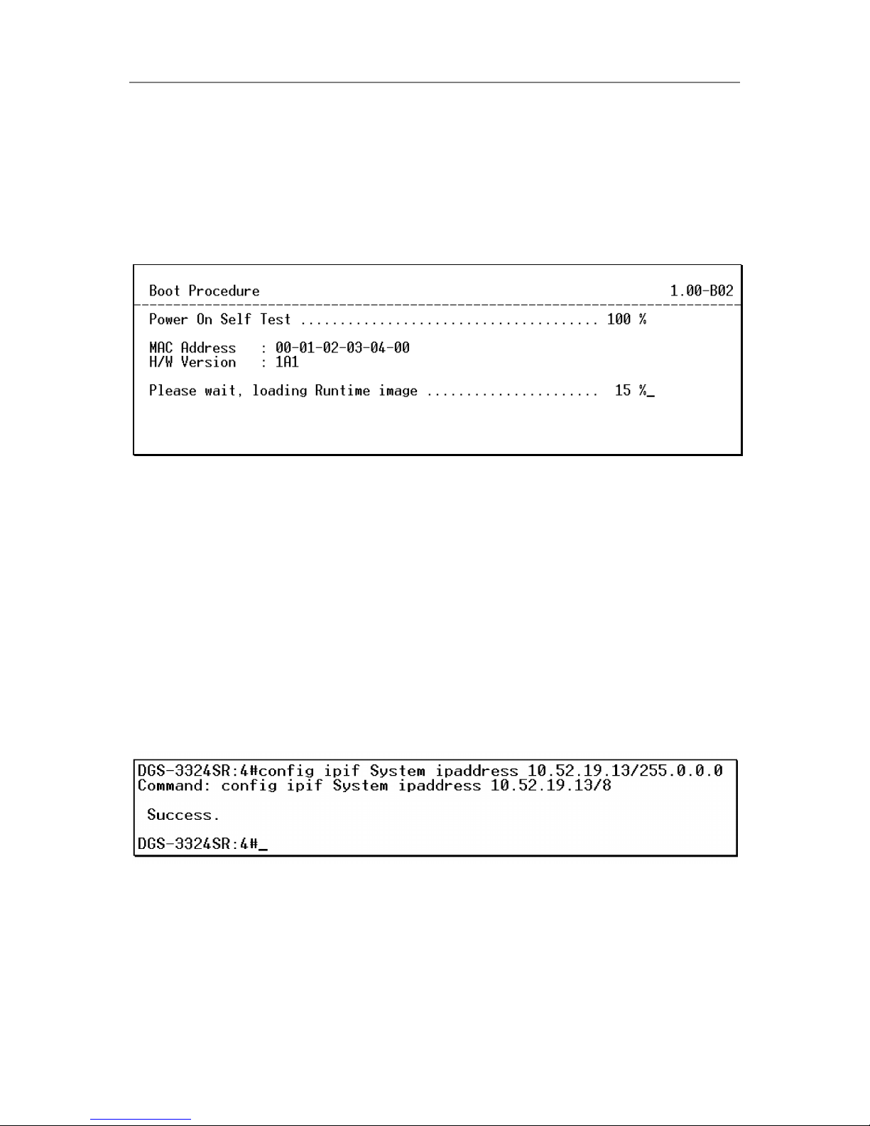
The Switch is also assigned a unique MAC address by the factory. This MAC address cannot be changed, and
can be found from the initial boot console screen – shown below.
Figure 2 - 4. Boot Screen
The Switch’s MAC address can also be found from the Web management program on the Switch Information
(Basic Settings) window on the Configuration menu.
The IP address for the Switch must be set before it can be managed with the Web-based manager. The Switch IP
address can be automatically set using BOOTP or DHCP protocols, in which case the actual address assigned to
the switch must be known.
The IP address may be set using the Command Line Interface (CLI) over the console serial port as follows:
1. Starting at the command line prompt, enter the commands config ipif System ipaddress
xxx.xxx.xxx.xxx/yyy.yyy.yyy.yyy. Where the x’s represent the IP address to be assigned to the IP
interface named System and the y’s represent the corresponding subnet mask.
2. Alternatively, you can enter config ipif System ipaddress xxx.xxx.xxx.xxx/z. Where the x’s represent
the IP address to be assigned to the IP interface named System and the z represents the corresponding
number of subnets in CIDR notation.
The IP interface named System on the Switch can be assigned an IP address and subnet mask which can then be
used to connect a management station to the Switch’s Telnet or Web-based management agent.
Figure 2 - 5. Assigning the Switch an IP Address
In the above example, the Switch was assigned an IP address of 10.52.19.13 with a subnet mask of 255.0.0.0.
The system message Success indicates that the command was executed successfully. The Switch can now be
configured and managed via Telnet and the CLI or via the Web-based management.
Page 29

D-Link DGS-3324SR Layer 3 Stackable Gigabit Ethernet Switch
14
Connecting Devices to the Switch
After assigning IP addresses to the Switch, you can connect devices to the Switch.
To connect a device to an SFP transceiver port:
1. Use your cabling requirements to select an appropriate SFP transceiver type.
2. Insert the SFP transceiver (sold separately) into the SFP transceiver slot.
3. Use the appropriate network cabling to connect a device to the connectors on the SFP transceiver.
NOTICE: When the SFP transceiver acquires a link, the associated
integrated 10/100/1000BASE-T port is disabled.
Page 30
D-Link DGS-3324SR Layer 3 Stackable Gigabit Ethernet Switch
15
Section 3
Introduction to Switch Management
Login to Web Manager
Web-based User Interface
Basic Setup
Switch Information
IP Address
User Accounts
Saving Changes
Factory Reset
Restart System
Introduction
All software functions of the DGS-3324SR can be managed, configured and monitored via the embedded webbased (HTML) interface. The switch can be managed from remote stations anywhere on the network through a
standard browser such as Netscape Navigator/Communicator or Microsoft Internet Explorer. The browser acts as
a universal access tool and can communicate directly with the Switch using the HTTP protocol.
The Web-based management module and the Console program (and Telnet) are different ways to access the same
internal switching software for configuration. Thus, all settings encountered in web-based management are the
same as those found in the console program.
Login to Web Manager
To begin managing your Switch simply run the browser you have installed on your computer and point it to the
IP address you have defined for the device. The URL in the address bar should read something like:
http://123.123.123.123, where the numbers 123 represent the IP address of the switch.
NOTE: The Factory default IP address for the Switch is 10.90.90.90.
In the page that opens, click on the Login to make a setup button at the top of the window:
Figure 3- 1. Login Page
This opens the management module’s main page.
The switch management features available in the web-based manager are explained below.
This opens the management module’s user authentication window, as seen below.
Page 31
D-Link DGS-3324SR Layer 3 Stackable Gigabit Ethernet Switch
16
Figure 3- 2. Enter Network Password window
Leave both the User Name field and the Password field blank and click OK. This will open the Web-based user
interface. The Switch management features available in the web-based manager are explained below.
Web-based User Interface
The user interface provides access to various switch configuration and management screens, allows you to view
performance statistics, and permits you to graphically monitor the system status.
Areas of the User Interface
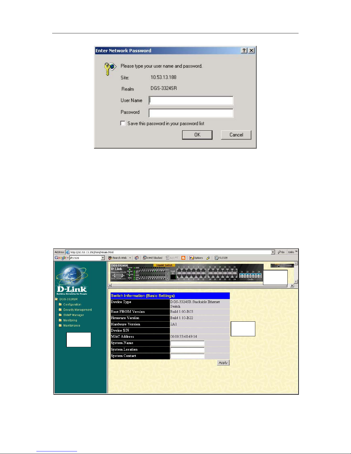
The figure below shows the user interface. The user interface is divided into 3 distinct areas as described in the
table.
Figure 3- 3. Main Web-Manager Screen
Area 1
Area 2
Area 3
Page 32

D-Link DGS-3324SR Layer 3 Stackable Gigabit Ethernet Switch
17
Area Function
1
Presents a graphical near real-time image of the front panel of the Switch. This area
displays the Switch’s ports and expansion modules, showing port activity, duplex
mode, or flow control, depending on the specified mode. To the right of the Switch’s
front panel is the current stacking configuration.
Various areas of the graphic can be selected for performing management functions,
including port configuration.
2
Select the menu or window to be displayed. The folder icons can be opened to
display the hyperlinked menu buttons and subfolders contained within them. Click
the D-Link logo to go to the D-Link website.
3
Presents switch information based on your selection and the entry of configuration
data.
NOTICE: Any changes made to the Switch configuration during the
current session must be saved in the Save Changes web menu
(explained below) or use the command line interface (CLI) command
save.
Web Pages
When you connect to the management mode of the Switch with a web browser, a login screen is displayed. Enter
a user name and password to access the Switch’s management mode.
Below is a list and description of the main folders available in the web interface:
Configuration folder: includes menus for port configuration, bandwidth control, link aggregation, port
mirroring, VLANs configuration, Spanning Tree Protocol setup, forwarding & filtering configuration, Quality of
Service, broadcast/multicast storm controls (Traffic Control), IGMP snooping, static router ports setup, SysLog
server setup, port security, SNTP settings and the access profile table. This also contains the Advanced Settings
menu which is used to configure miscellaneous settings such as for the serial port, MAC address aging time, and
to enable/disable the following: RMON, IGMP snooping, Telnet and web management access, traffic
segmentation, and 802.1x. The Switch Information page is used to enter system contact and physical location
information and lists basic information such as the switch’s MAC address, current firmware version and the
modules installed.
Security Management: contains 802.1x settings including RADIUS server information and PAE setup and
security management IP station setup.
SNMP Manager: contains menus for establishing the Switch IP settings, user accounts configuration and SNMP
setup including SNMP v.3 configuration.
Monitoring: includes menus for monitoring Switch performance monitors, MAC address table information,
router port information, IGMP Snooping information and 802.1x related information.
Maintenance: contains menus for upgrading firmware and saving configuration files (TFTP Services), saving
configuration changes, resetting and rebooting the Switch, Ping test and logging out of the web manager.
NOTE: Be sure to configure the user name and password in the User
Accounts menu before connecting the Switch to the greater network.
Page 33
D-Link DGS-3324SR Layer 3 Stackable Gigabit Ethernet Switch
18
Basic Setup
The subsections below describe how to change some of the basic settings for the Switch such as changing IP
settings and assigning user names and passwords for management access privileges, as well as how to save the
changes and restart the Switch.
Switch Information
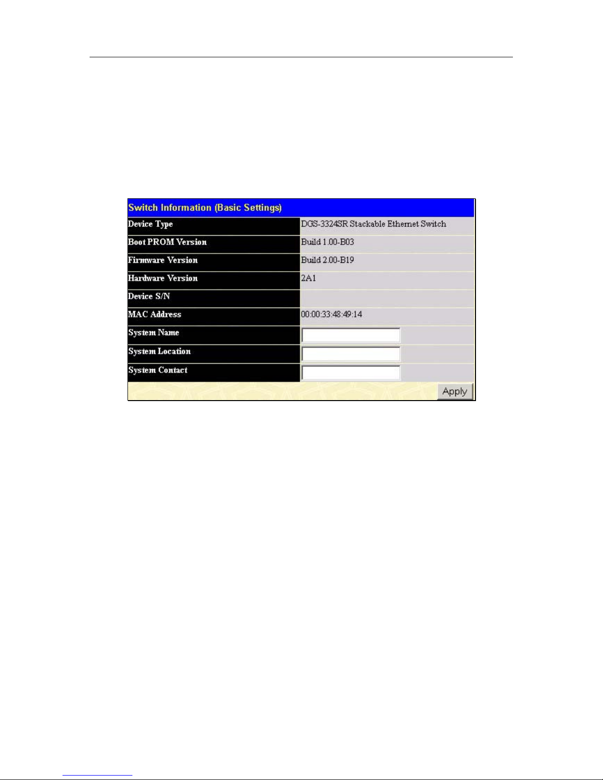
Click the Switch Information link in the Configuration menu.
Figure 3- 4. Switch Information – Basic Settings
The Switch Information window shows the Switch’s MAC Address (assigned by the factory and
unchangeable). In addition, the Boot PROM and Firmware Version numbers are shown. This information is
helpful to keep track of PROM and Firmware updates and to obtain the Switch’s MAC address for entry into
another network device’s address table – if necessary.
You may assign a System Name, System Location, and System Contact. If any changes or additions are made,
click Apply to implement them.
Switch IP Settings
Switch IP settings may initially be set using the console interface prior to connecting to it through the Ethernet. If
the Switch IP address has not yet been changed, read the Introduction of the CLI Reference or skip ahead to the
end of this section for a quick description of how to use the console port and CLI IP settings commands to
establish IP settings for the switch.
To change IP settings using the web manager you must access the IP Address menu located in the
Configuration folder.
To configure the Switch’s IP address:
Open the Configuration folder and click the IP Address link. The web manager will display the Switch IP
Settings menu below.
Page 34
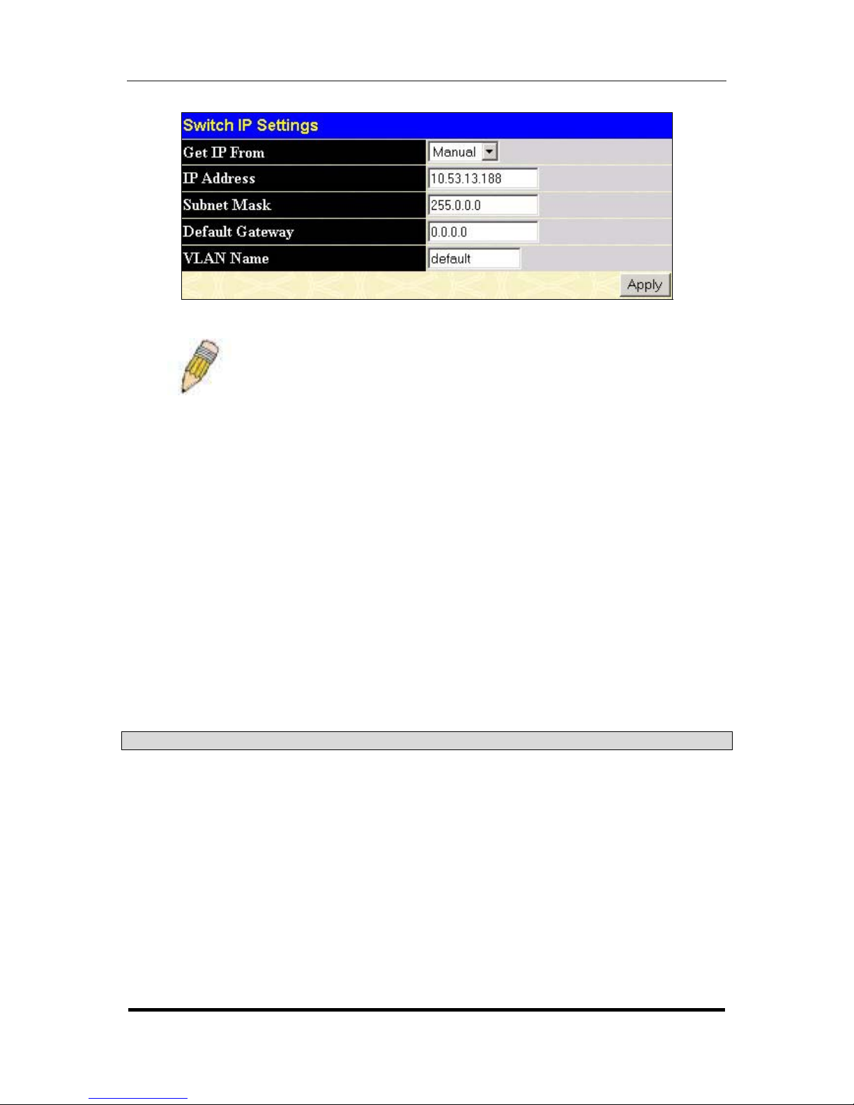
D-Link DGS-3324SR Layer 3 Stackable Gigabit Ethernet Switch
19
Figure 3- 5. Configure Switch IP Settings
NOTE: The Switch’s factory default IP address is 10.90.90.90 with a
subnet mask of 255.0.0.0 and a default gateway of 0.0.0.0.
To manually assign the Switch’s IP address, subnet mask, and default gateway address:
-Select Manual from the Get IP From drop-down menu.
-Enter the appropriate IP address and subnet mask.
-If you want to access the Switch from a different subnet from the one it is installed on, enter the IP address of
the gateway. If you will manage the Switch from the subnet on which it is installed, you can leave the default
address (0.0.0.0) in this field.
If no VLANs have been previously configured on the Switch, you can use the default VLAN Name “default”.
The default VLAN contains all of the Switch ports as members. If VLANs have been previously configured on
the Switch, you will need to enter the VLAN Name of the VLAN that contains the port connected to the
management station that will access the Switch. The Switch will allow management access from stations with the
same VLAN Name listed here.
To use the BOOTP or DHCP protocols to assign the switch an IP address, subnet mask, and default gateway
address:
Use the Get IP From: <Manual> pull-down menu to choose from BOOTP or DHCP. This selects how the
Switch will be assigned an IP address on the next reboot.
The Switch IP Settings options are:
Parameter Description
BOOTP
The Switch will send out a BOOTP broadcast request when it is powered up.
The BOOTP protocol allows IP addresses, network masks, and default
gateways to be assigned by a central BOOTP server. If this option is set, the
Switch will first look for a BOOTP server to provide it with this information
before using the default or previously entered settings.
DHCP
The Switch will send out a DHCP broadcast request when it is powered up.
The DHCP protocol allows IP addresses, network masks, and default
gateways to be assigned by a DHCP server. If this option is set, the Switch
will first look for a DHCP server to provide it with this information before using
the default or previously entered settings.
Manual
Allows the entry of an IP address, Subnet Mask, and a Default Gateway for
the Switch. These fields should be of the form xxx.xxx.xxx.xxx, where each
xxx is a number (represented in decimal form) between 0 and 255. This
address should be a unique address on the network assigned for use by the
Page 35

D-Link DGS-3324SR Layer 3 Stackable Gigabit Ethernet Switch
20
network administrator. The fields which require entries under this option are
as follows:
Subnet Mask
A Bitmask that determines the extent of the subnet that the Switch is on.
Should be of the form xxx.xxx.xxx.xxx, where each xxx is a number
(represented in decimal) between 0 and 255. The value should be 255.0.0.0
for a Class A network, 255.255.0.0 for a Class B network, and 255.255.255.0
for a Class C network, but custom subnet masks are allowed.
Default Gateway
IP address that determines where packets with a destination address outside
the current subnet should be sent. This is usually the address of a router or a
host acting as an IP gateway. If your network is not part of an intranet, or you
do not want the Switch to be accessible outside your local network, you can
leave this field unchanged.
VLAN Name
This allows the entry of a VLAN Name from which a management station will
be allowed to manage the switch using TCP/IP (in-band via web manager or
Telnet). Management stations that are on VLANs other than the one entered
in the VLAN Name field will not be able to manage the switch in-band unless
their IP addresses are entered in the Security IP Management menu. If
VLANs have not yet been configured for the switch, The default VLAN Name
contains all of the Switch’s ports. There are no entries in the Security IP
Management table, by default − so any management station that can connect
to the Switch can access the Switch until either a management VLAN is
specified or Management Station IP Addresses are assigned.
Setting the Switch’s IP Address using the Console Interface
Each Switch must be assigned its own IP Address, which is used for communication with an
SNMP network manager or other TCP/IP application (for example BOOTP, TFTP). The
Switch’s default IP address is 10.90.90.90. You can change the default Switch IP address to
meet the specification of your networking address scheme.
The IP address for the Switch must be set before it can be managed with the Web-
b
ased
manager. The Switch IP address can be automatically set using BOOTP or DHCP protocols, in
which case the actual address assigned to the Switch must be known.
The IP address may be set using the Command Line Interface (CLI) over the console serial por
t
as follows:
Starting at the command line prompt, enter the commands confi
g
ipif System ipaddress
xxx.xxx.xxx.xxx/yyy.yyy.yyy.yyy. Where the x’s represent the IP address to be assigned to the
IP interface named System and the y’s represent the corresponding subnet mask.
Alternatively, you can enter config ipif System ipaddress xxx.xxx.xxx.xxx/z. Where the x’s
represent the IP address to be assigned to the IP interface named System and the z represents
the corresponding number of subnets in CIDR notation.
The IP interface named System on the Switch can be assigned an IP address and subnet mas
k
which can then be used to connect a management station to the Switch’s Telnet or Web-based
management agent.
The system message Success indicates that the command was executed successfully. The
Switch can now be configured and managed via Telnet and the CLI or via the Web-
b
ased
management agent using the above IP address to connect to the Switch.
Page 36
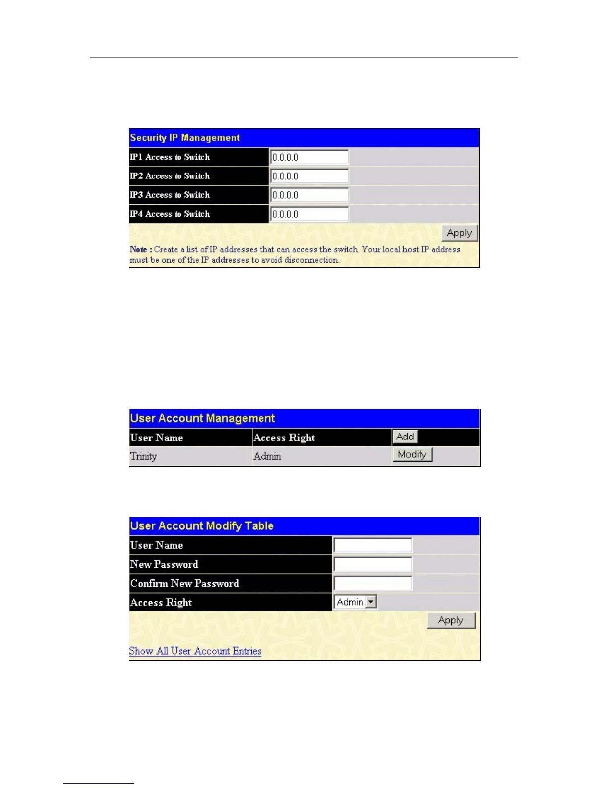
D-Link DGS-3324SR Layer 3 Stackable Gigabit Ethernet Switch
21
Security IP Management Stations Configuration
Go to the Security Management folder and click on Security IP; the following screen will appear.
Figure 3- 6. Security IP Management Setup
Use the Management Station IP Settings to select up to three management stations used to manage the Switch.
If you choose to define one or more designated management stations, only the chosen stations, as defined by IP
address, will be allowed management privilege through the web manager or Telnet session. To define a
management station IP setting, type in the IP address and click on the Apply button.
User Accounts Management
Use the User Accounts Management window to control user privileges. To view existing User Accounts, open
the Security Management folder and click on the User Accounts link. This will open the User Account
Management page, as shown below.
Figure 3- 7. User Accounts Management Table
To add a new user, click on the Add button. To modify or delete an existing user, click on the Modify button for
that user.
Figure 3- 8. Add User Accounts Modify Table
Add a new user by typing in a User Name, and New Password and retype the same password in the Confirm
New Password. Choose the level of privilege (Admin or User) from the Access Right drop-down menu. To add
a user account using the CLI commands use create account and config account.
Page 37
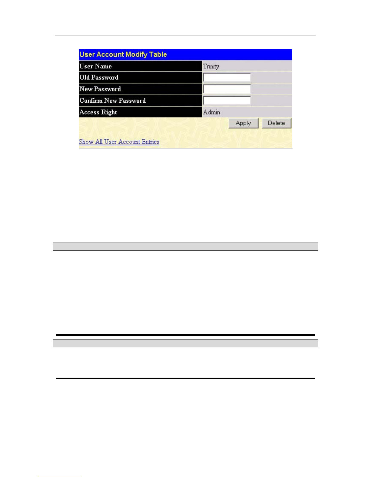
D-Link DGS-3324SR Layer 3 Stackable Gigabit Ethernet Switch
22
Figure 3- 9. Modify User Accounts
Modify or delete an existing user account in the User Account Modify Table. To delete the user account, click
on the Delete button. To change the password, type in the New Password and retype it in the Confirm New
Password entry field. Choose the level of privilege (Admin or User) from the Access Right drop-down menu.
To delete a user account using CLI use the command delete account. To change an existing account use config
account.
Admin and User Privileges
There are two levels of user privileges: Admin and User. Some menu selections available to users with Admin
privileges may not be available to those with User privileges.
The following table summarizes the Admin and User privileges:
Management Admin User
Configuration
Yes Read Only
Network Monitoring
Yes Read Only
Community Strings and Trap Stations
Yes Read Only
Update Firmware and Configuration Files
Yes No
System Utilities
Yes Ping Only
Factory Reset
Yes No
User Account Management
Add/Update/Delete User Accounts
Yes No
View User Accounts
Yes No
Admin and User Privileges
After establishing a User Account with Admin-level privileges, be sure to save the changes (see below).
Saving Changes
Changes made to the Switch’s configuration must be saved in order to retain them. Access the Save
Configuration by clicking the Save Changes button located in the Maintenance folder.
Page 38
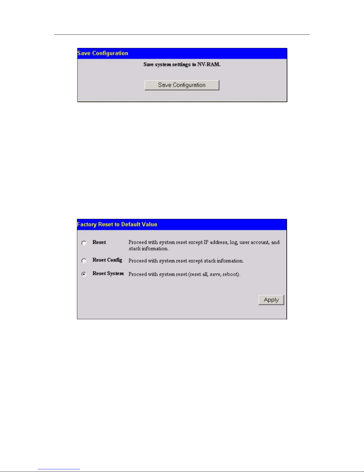
D-Link DGS-3324SR Layer 3 Stackable Gigabit Ethernet Switch
23
Figure 3- 10. Save Configuration window
The Switch has two levels of memory, normal RAM and non-volatile or NV-RAM. To save all the changes
made in the current session to the Switch’s flash memory, click the Save Configuration button. Click the OK
button in the new dialog box that appears to continue. When this is done, the settings will be immediately applied
to the switching software in RAM, and will immediately take effect. Once the Switch configuration settings have
been saved to NV-RAM, they become the default settings for the Switch. These settings will be used every time
the Switch is rebooted.
Some settings, though, require you to restart the Switch before they will take effect. Restarting the Switch erases
all settings in RAM and reloads the stored settings from the NV-RAM. Thus, it is necessary to save all setting
changes to NV-RAM before rebooting the Switch.
To save settings using CLI the command is save.
Factory Reset
Click the Reset link in the Maintenance folder to bring up the reset menu.
Figure 3- 11. Factory Reset to Default Value window
Reset − returns all configuration settings except the Switch’s IP address, subnet mask, default gateway, log, user
account and stack information settings to the factory default settings.
Reset Config − returns all configuration settings except the stack information settings to the factory default
settings, but does not save the settings or reboot the Switch. If you select this option the switch configuration will
be returned to the factory default settings for the current session only. When the Switch is rebooted, it will return
to the last configuration saved to the switch’s NV-RAM using the Save Changes option.
Reset System − returns the switch configuration to the factory default settings and then saves the factory default
configuration to the Switch’s NV-RAM. The Switch will then reboot. When the Switch has rebooted, it will have
the same configuration as when it was delivered from the factory.
Page 39
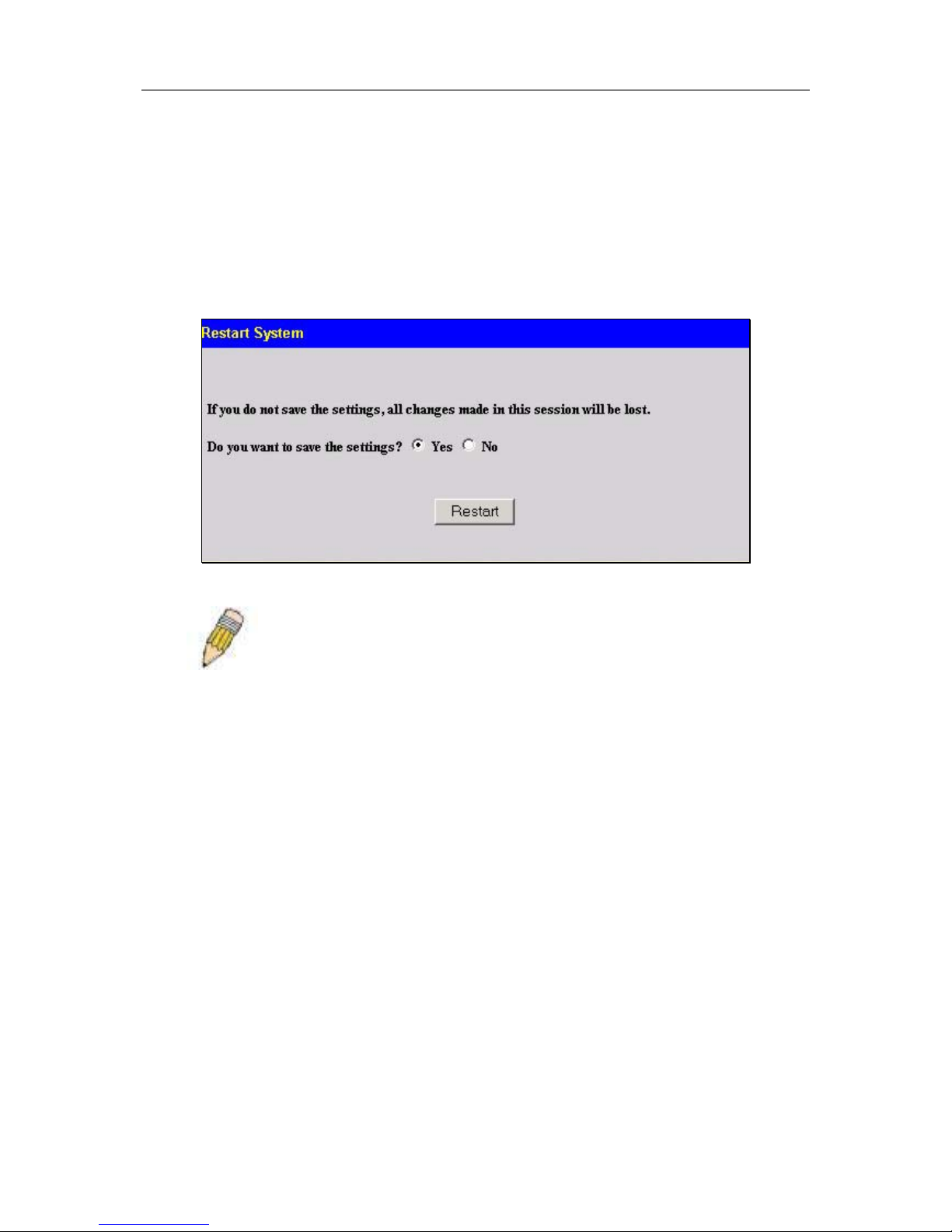
D-Link DGS-3324SR Layer 3 Stackable Gigabit Ethernet Switch
24
Restart System
The following menu is used to restart the Switch. Access this menu by clicking on the Reboot Device link in the
Maintenance folder.
Click the Yes after Do you want to save the settings? to instruct the Switch to save the current configuration to
non-volatile RAM before restarting the Switch.
Clicking the No option instructs the Switch not to save the current configuration before restarting the Switch.
All of the configuration information entered since the last time Save Changes was executed will be lost.
Click the Restart button to restart the Switch.
Figure 3- 12. Restart System
NOTE: Clicking Yes is equivalent to executing Save Changes and then
restarting the Switch.
Switch Information
The first page displayed upon logging in presents the System Information menu. This page can be accessed at
any time by clicking the Switch Information link in the Configuration folder.
Page 40
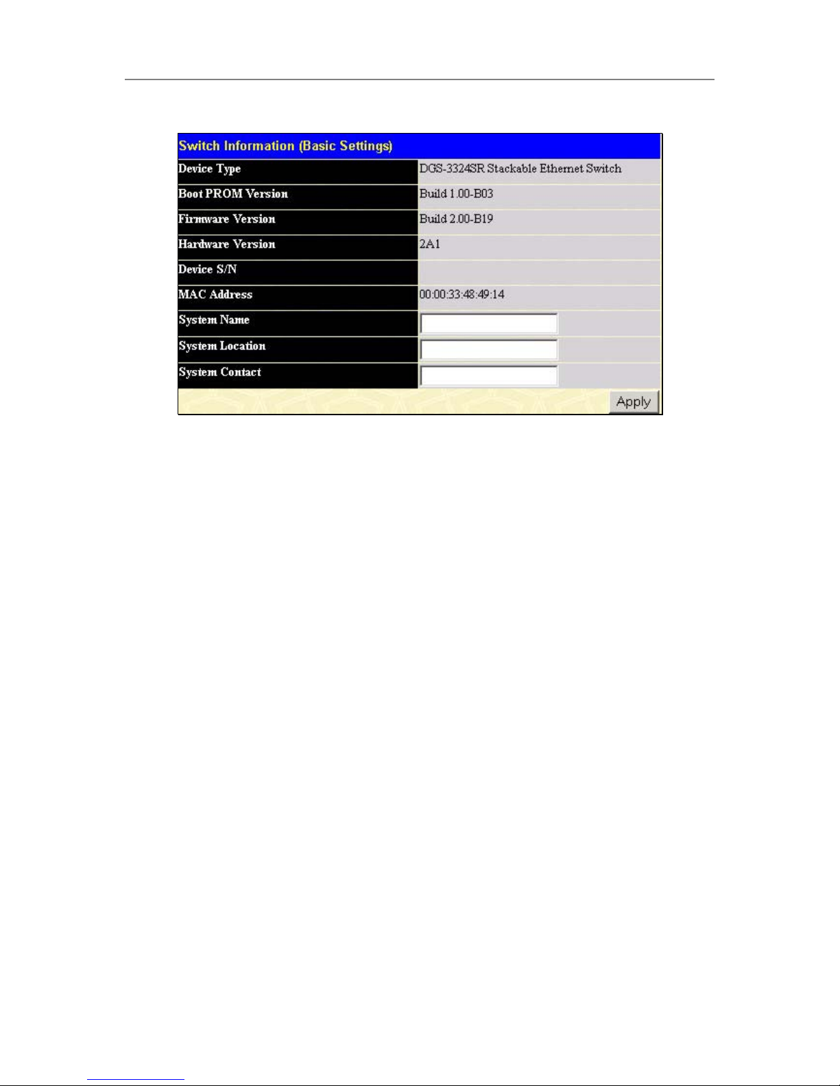
D-Link DGS-3324SR Layer 3 Stackable Gigabit Ethernet Switch
25
Figure 3- 13. Switch Information
The System Information page displays general information about the Switch including its MAC Address,
Hardware Boot PROM and Firmware versions, and other optional information.
You can also enter or change a System Name, System Location, and the name and telephone number of the
responsible administrator in the System Contact. It is recommended that the person responsible for the
maintenance of the network system be listed here. Click on the Apply button to make the changes effective.
To view this information using Telnet use CLI command show switch.
Advanced Settings
The Advanced Settings window contains the main settings for all major functions for the Switch. To view the
Advanced Settings window, click its link in the Configuration folder. This will enable the following window to
be viewed and configured.
Page 41
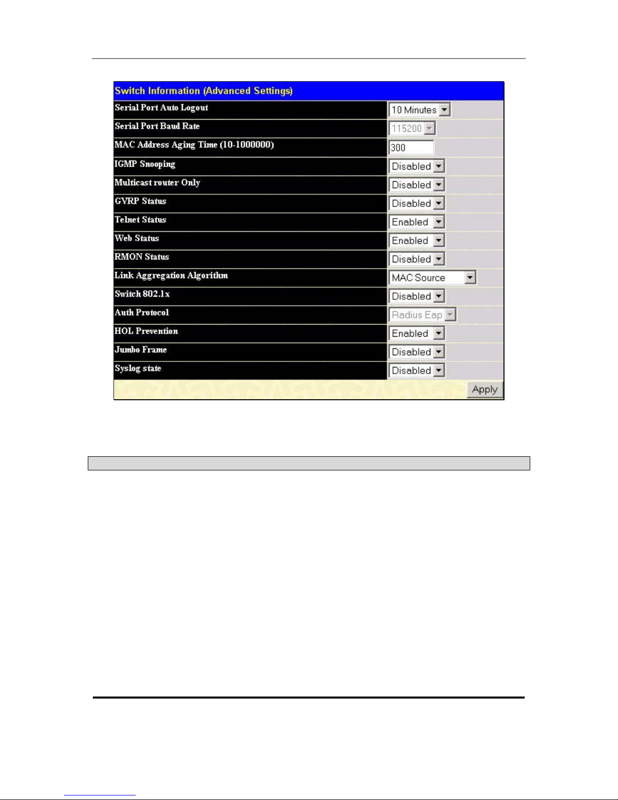
D-Link DGS-3324SR Layer 3 Stackable Gigabit Ethernet Switch
26
Figure 3- 14. Switch Information − Advanced Settings
The Advanced Settings menu options are summarized in the table below.
Variables in the Advanced Settings menu of the Web Manager are as follows:
Parameter Description
Serial Port Auto
Logout
Select the logout time used for the console interface. This automatically
logs the user out after an idle period of time as defined. Choose from the
following options: 2 Minutes, 5 Minutes, 10 Minutes, 15 Minutes or Never.
Serial Port Baud
Rate
Fixed at 115200.
MAC Address Aging
Time
This field specifies the length of time a learned MAC Address will remain in
the forwarding table without being accessed (that is, how long a learned
MAC Address is allowed to remain idle). The default age-out time for the
Switch is 300 seconds. To change this, type in a different value
representing the MAC address age-out time in seconds. The Aging Time
can be set to any value between 10 and 1,000,000 seconds.
IGMP Snooping
To enable system-wide IGMP Snooping capability select Enabled. IGMP
snooping is Disabled by default. Enabling IGMP snooping allows you to
specify use of a multicast router only (see below). To configure IGMP
Snooping for individual VLANs, use the IGMP Snooping page under the
IGMP folder.
Page 42

D-Link DGS-3324SR Layer 3 Stackable Gigabit Ethernet Switch
27
Multicast Router
Only
If this option is enabled and IGMP Snooping is also enabled, the Switch
forwards all multicast traffic to a multicast-enabled router only. Otherwise,
the Switch will forward all multicast traffic to any IP router.
GVRP Status
Use this pull-down menu to Enable or Disable GVRP on the Switch.
Telnet Status
Telnet configuration is Enabled by default. If you do not want to allow
configuration of the system through Telnet choose Disabled.
Web Status
Web-based management is Enabled by default. If you choose to disable
this by selecting Disabled, you will lose the ability to configure the system
through the web interface as soon as these settings are applied.
RMON Status
Remote monitoring (RMON) of the Switch is Enabled or Disabled here.
Link Aggregation
Algorithm
The algorithm that the Switch uses to balance the load across the ports
that make up the port trunk group is defined by this definition. Choose
MAC Source, MAC Destination, MAC Src & Dest, IP Source, IP
Destination or IP Src & Dest (See the Link Aggregation section of this
manual).
Switch 802.1x
Enables or disables 802.1x; default is Disabled.
Auth Protocol
The user may choose between Local and Radius Eap.
HOL Prevention
Enables or disables HOL (Head of Line) prevention; default is Enabled.
Jumbo Frame
Enables or disables Jumbo Frame acceptance; default is Disabled.
Syslog State
Enables or disables Syslog State; default is Disabled.
Page 43
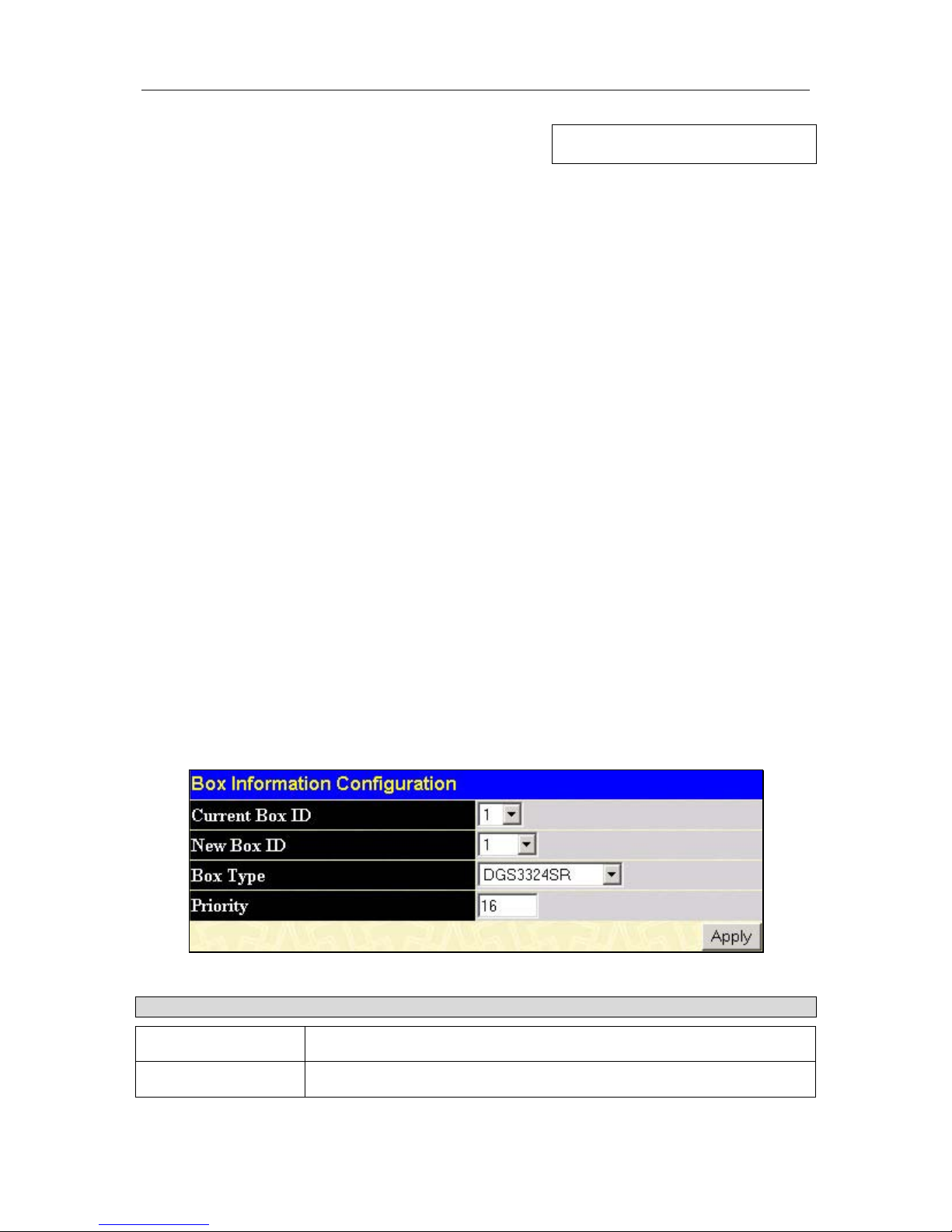
D-Link DGS-3324SR Layer 3 Stackable Gigabit Ethernet Switch
28
Section 4
Configuration
Configuring Box Information
Configuring Ports
Configuring Port Mirroring
Configuring Link Aggregation
Configuring IGMP
Configuring The Spanning Tree
Configuring Forwarding and Filtering
Configuring VLANs
Configuring Traffic Control
Configuring Port Security
Configuring QoS
The System Log Server
Configuring SNTP Settings
Configuring The Access Profile Table
Configuring The Port Access Entity
Configuring Layer 3 IP Networking
Configuring Box Information
The Box Information Configuration screen can be found in the Configuration folder under the heading Box
Information. This window is used to configure the Master switch of a switch stack. The Master switch is the
switch that will be used to configure the software applications regarding the switch stack.
Figure 4- 1. Box Information Configuration window
Parameter Description
Current Box ID
The current Box ID of the Master switch in the stack.
New Box ID
The new box ID of the Master switch in the stack.
Page 44
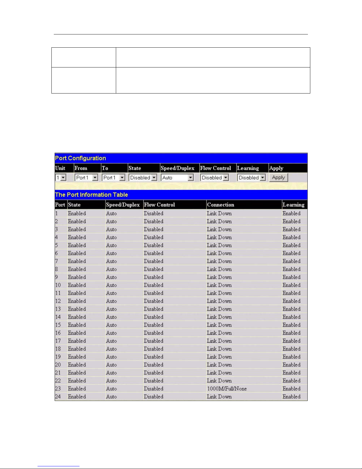
D-Link DGS-3324SR Layer 3 Stackable Gigabit Ethernet Switch
29
Box Type
The user may choose the model name of the Master switch in a stack to be
the main configuring switch of that stack.
Priority
Displays the priority ID of the Switch. The lower the number, the higher the
priority. The box (switch) with the lowest priority number in the stack is the
Master switch.
Information configured in this screen may be found in the Monitoring folder under Stack Information.
Configuring Ports
This section contains information for configuring various attributes and properties for individual physical ports,
including port speed and flow control. Clicking on Port Configurations in the Configuration menu will display
the following window for the user:
Figure 4- 2. Port Configuration menu
Page 45

D-Link DGS-3324SR Layer 3 Stackable Gigabit Ethernet Switch
30
To configure switch ports:
1. Choose the Unit from the pull-down menu.
2. Choose the port or sequential range of ports using the From…To… port pull-down menus.
3. Use the remaining pull-down menus to configure the parameters described below:
Parameter Description
State <Enabled> Toggle the State <Enabled> field to either enable or disable a given port or
group of ports.
Speed/Duplex
<Auto>
Toggle the Speed/Duplex <Auto> field to either select the speed and
duplex/half-duplex state of the port. Auto – auto-negotiation between 10 and
1000 Mbps devices, full- or half-duplex. The Auto setting allows the port to
automatically determine the fastest settings the device the port is connected
to can handle, and then to use those settings. The other options are Auto,
10M/Half, 10M/Full, 100M/Half, 100M/Full, 1000M/Full_M (master), and
1000M/Full_S (slave). There is no automatic adjustment of port settings with
any option other than Auto.
Flow Control
Displays the flow control scheme used for the various port configurations.
Ports configured for full-duplex use 802.3x flow control, half-duplex ports use
backpressure flow control, and Auto ports use an automatic selection of the
two. The default is Disabled.
Learning
Enable or disable MAC address learning for the selected ports. When
Enabled, destination and source MAC addresses are automatically listed in
the forwarding table. When learning is Disabled, MAC addresses must be
manually entered into the forwarding table. This is sometimes done for
reasons of security or efficiency. See the section on Forwarding/Filtering for
information on entering MAC addresses into the forwarding table.
Click Apply to implement the new settings on the Switch.
Configuring Port Mirroring
The Switch allows you to copy frames transmitted and received on a port and redirect the copies to another port.
You can attach a monitoring device to the mirrored port, such as a sniffer or an RMON probe, to view details
about the packets passing through the first port. This is useful for network monitoring and troubleshooting
purposes. To view the Setup Port Mirroring window, click Port Mirroring in the Configuration folder.
Page 46
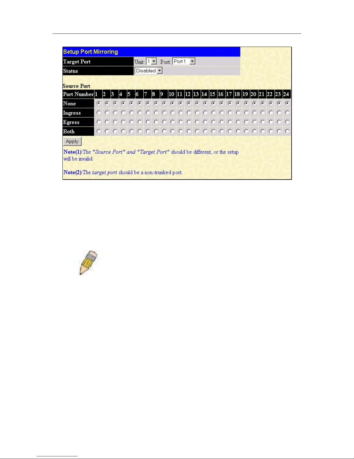
D-Link DGS-3324SR Layer 3 Stackable Gigabit Ethernet Switch
31
Figure 4- 3. Setup Port Mirroring window
To configure a mirror port:
1. Select the Source Port from where you want to copy frames and the Target Port, which receives the
copies from the source port.
2. Select the Source Direction, Ingress, Egress, or Both and change the Status drop-down menu to
Enabled.
3. Click Apply to let the changes take effect.
NOTE: You cannot mirror a fast port onto a slower port. For example, if
you try to mirror the traffic from a 100 Mbps port onto a 10 Mbps port, this
can cause throughput problems. The port you are copying frames from
should always support an equal or lower speed than the port to which you
are sending the copies. Also, the target port for the mirroring cannot be a
member of a trunk group. Please note a target port and a source port
cannot be the same port.
Configuring Link Aggregation
Understanding Port Trunk Groups
Port trunk groups are used to combine a number of ports together to make a single high-bandwidth data pipeline.
The DGS-3324SR supports up to 32 port trunk groups with 2 to 8 ports in each group. A potential bit rate of
8000 Mbps can be achieved.
Page 47
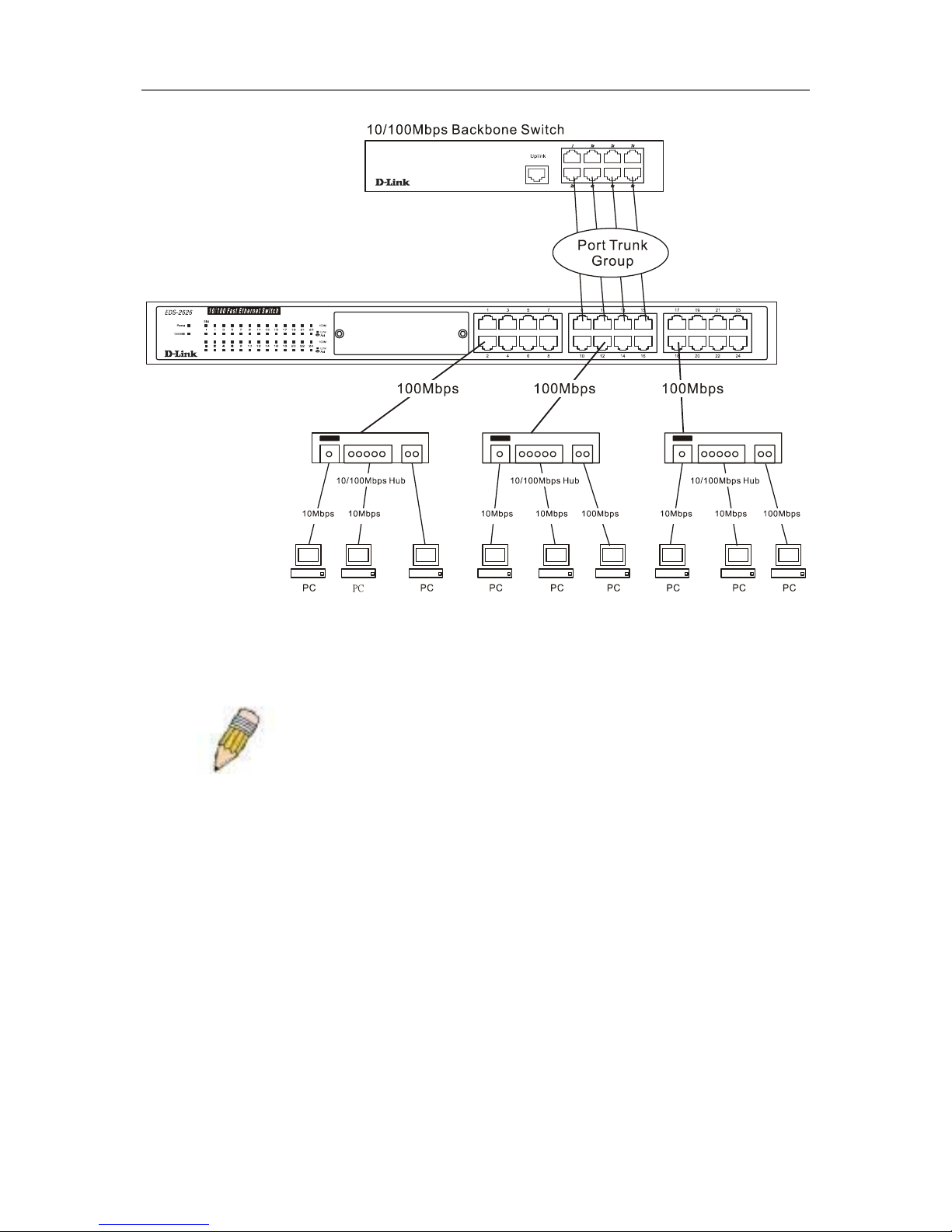
D-Link DGS-3324SR Layer 3 Stackable Gigabit Ethernet Switch
32
Figure 4- 4. Example of Port Trunk Group
The Switch treats all ports in a trunk group as a single port. Data transmitted to a specific host (destination
address) will always be transmitted over the same port in a trunk group. This allows packets in a data stream to
arrive in the same order they were sent.
Note: If any ports within the trunk group become disconnected, packets
intended for the disconnected port will be load shared among the other
uplinked ports of the link aggregation group.
Link aggregation allows several ports to be grouped together and to act as a single link. This gives a bandwidth
that is a multiple of a single link’s bandwidth.
Link aggregation is most commonly used to link a bandwidth intensive network device or devices, such as a
server, to the backbone of a network.
The Switch allows the creation of up to 32 link aggregation groups, each group consisting of 2 to 8 links (ports).
The aggregated links must be contiguous (they must have sequential port numbers) except the two (optional)
Gigabit ports, which can only belong to a single link aggregation group. All of the ports in the group must be
members of the same VLAN, and their STP status, static multicast, traffic control, traffic segmentation, 802.1p
default priority configurations must be identical. Port locking , port mirroring and 802.1X must not be enabled
on the trunk group. Further, the aggregated links must all be of the same speed and should be configured as fullduplex.
The Master Port of the group is to be configured by the user, and all configuration options, including the VLAN
configuration, that can be applied to the Master Port are applied to the entire link aggregation group.
Load balancing is automatically applied to the ports in the aggregated group, and a link failure within the group
causes the network traffic to be directed to the remaining links in the group.
The Spanning Tree Protocol will treat a link aggregation group as a single link, on the switch level. On the port
level, the STP will use the port parameters of the Master Port in the calculation of port cost and in determining
Page 48
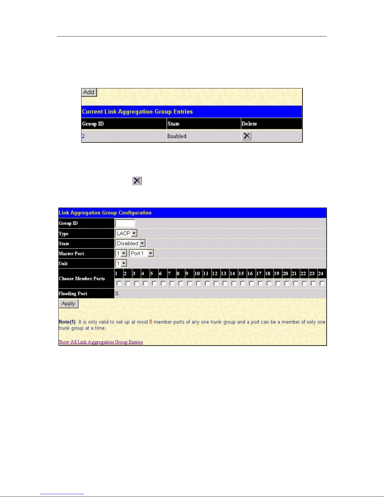
D-Link DGS-3324SR Layer 3 Stackable Gigabit Ethernet Switch
33
the state of the link aggregation group. If two redundant link aggregation groups are configured on the switch,
STP will block one entire group, in the same way STP will block a single port that has a redundant link.
To configure port trunking, click on the Link Aggregation hyperlink in the Configuration folder to bring up the
Current Link Aggregation Group Entries table:
Figure 4- 5. Current Link Aggregation Group Entries window
To configure port trunk groups, click the Add button to add a new trunk group and use the menu Link
Aggregation Group Configuration menu (see example below) to set up trunk groups. To modify a port trunk
group, double-click on it to bring up the Link Aggregation Group Configuration menu. To delete a port trunk
group, click the corresponding
under the Delete heading in the Current Link Aggregation Group Entries
table.
Figure 4- 6. Link Aggregation Group Configuration window – Add
Page 49
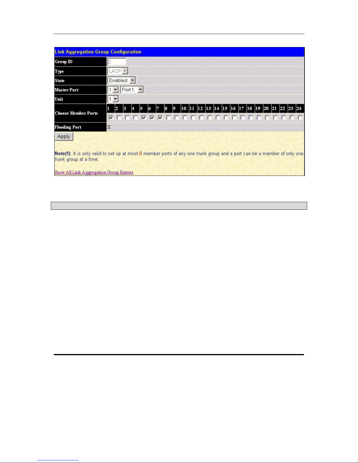
D-Link DGS-3324SR Layer 3 Stackable Gigabit Ethernet Switch
34
Figure 4- 7. Link Aggregation Group Configuration window – Modify
The user-changeable parameters are as follows:
Parameter Description
Group ID
Select an ID number for the group, between 1 and 32.
Type
This pull-down menu allows you to select between Static and LACP (Link
Aggregation Control Protocol.) LACP allows for the automatic detection of
links in a Port Trunking Group.
State
Trunk groups can be toggled between Enabled and Disabled. This is used
to turn a port trunking group on or off. This is useful for diagnostics, to
quickly isolate a bandwidth intensive network device or to have an absolute
backup aggregation group that is not under automatic control.
Master Port
Choose the Master port for the trunk group.
Unit
Choose the number representing the Switch in the stack for which you
would like to configure a Link Aggregation Group for.
Choose Member
Ports
Choose the members of a trunked group. Up to 8 ports per group can be
assigned to a group.
Flooding Port
A trunking group must designate one port to allow transmission of
broadcasts and unknown unicasts.
After setting the previous parameters, click Apply to allow your changes to be implemented. Successfully created
trunk groups will be show in the Current Link Aggregation Group Entries as seen in Figure 4-5.
LACP Port Setting
The LACP Port Setting window is used in conjunction with the Link Aggregation window to create port trunking
groups on the Switch. Using the following window, the user may set which ports will be active and passive in
processing and sending LACP control frames.
Page 50

D-Link DGS-3324SR Layer 3 Stackable Gigabit Ethernet Switch
35
Figure 4- 8. LACP Port Setting and Information window
The user may set the following parameters:
Parameter Description
Unit
Choose the number representing the Switch in the stack for which you
would like to change the LACP Port mode.
From/To
A consecutive group of ports may be configured starting with the selected
port.
Mode
Active – Active LACP ports are capable of processing and sending LACP
control frames. This allows LACP compliant devices to negotiate the
aggregated link so the group may be changed dynamically as needs require.
In order to utilize the ability to change an aggregated port group, that is, to
add or subtract ports from the group, at least one of the participating devices
must designate LACP ports as active. Both devices must support LACP.
Passive – LACP ports that are designated as passive cannot initially send
LACP control frames. In order to allow the linked port group to negotiate
adjustments and make changes dynamically, at one end of the connection
must have “active” LACP ports (see above).
Page 51
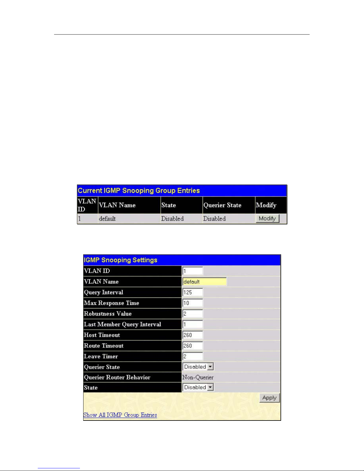
D-Link DGS-3324SR Layer 3 Stackable Gigabit Ethernet Switch
36
After setting the previous parameters, click Apply to allow your changes to be implemented. The LACP Port
Information Table shows which ports are active and/or passive.
Configuring IGMP
Internet Group Management Protocol (IGMP) snooping allows the Switch to recognize IGMP queries and
reports sent between network stations or devices and an IGMP host. When enabled for IGMP snooping, the
Switch can open or close a port to a specific device based on IGMP messages passing through the Switch.
In order to use IGMP Snooping it must first be enabled for the entire Switch (see Advanced Settings). You may
then fine-tune the settings for each VLAN using the IGMP Snooping link in the Configuration folder. When
enabled for IGMP snooping, the Switch can open or close a port to a specific Multicast group member based on
IGMP messages sent from the device to the IGMP host or vice versa. The Switch monitors IGMP messages and
discontinues forwarding multicast packets when there are no longer hosts requesting that they continue.
IGMP Snooping
Use the Current IGMP Snooping Group Entries window to view IGMP Snooping settings. To modify the
settings, click the Modify button of the VLAN ID you want to change.
Figure 4- 9. Current IGMP Snooping Group Entries
Clicking the Modify button will bring up the IGMP Snooping Settings menu.
Figure 4- 10. IGMP Snooping Settings window
Page 52

D-Link DGS-3324SR Layer 3 Stackable Gigabit Ethernet Switch
37
The following parameters may be viewed or modified:
Parameter Description
VLAN ID
This is the VLAN ID that, along with the VLAN name, identifies the VLAN
which the user wishes to modify the IGMP Snooping Settings for.
VLAN Name
This is the VLAN Name that, along with the VLAN ID, identifies the
VLAN which the user wishes to modify the IGMP Snooping Settings for.
Query Interval
The Query Interval field is used to set the time (in seconds) between
transmitting IGMP queries. Entries between 1 and 9,999 seconds are
allowed. Default = 125.
Max Response Time
This determines the maximum amount of time in seconds allowed before
sending an IGMP response report. The Max Response Time field allows
an entry between 1 and 25 (seconds). Default = 10.
Robustness Variable
Adjust this variable according to expected packet loss. If packet loss on
the VLAN is expected to be high, the Robustness Variable should be
increased to accommodate increased packet loss. This entry field allows
an entry of 1 to 255. Default = 2.
Last Member Query
Interval
Specifies the maximum amount of time between group-specific query
messages, including those sent in response to leave group messages.
Default = 1.
Host Timeout
This is the maximum amount of time in seconds allowed for a host to
continue membership in a multicast group without the Switch receiving a
host membership report. Default = 260.
Route Timeout
This is the maximum amount of time in seconds a route is kept in the
forwarding table without receiving a membership report. Default = 260.
Leave Timer
This specifies the maximum amount of time in seconds between the
Switch receiving a leave group message from a host, and the Switch
issuing a group membership query. If no response to the membership
query is received before the Leave Timer expires, the (multicast)
forwarding entry for that host is deleted.
Querier State
Choose Enabled to enable transmitting IGMP Query packets or Disabled
to disable. The default value is Disabled.
State
Select Enabled to implement IGMP Snooping. This field is Disabled by
default.
Click Apply to implement the new settings, Click the Show All IGMP Group Entries link to return to the
Current IGMP Snooping Group Entries window.
Static Router Ports
A static router port is a port that has a multicast router attached to it. Generally, this router would have a
connection to a WAN or to the Internet. Establishing a router port will allow multicast packets coming from the
router to be propagated through the network, as well as allowing multicast messages (IGMP) coming from the
network to be propagated to the router.
Page 53
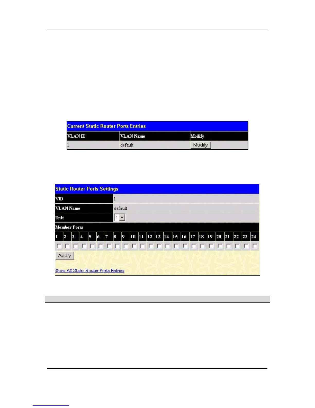
D-Link DGS-3324SR Layer 3 Stackable Gigabit Ethernet Switch
38
A router port has the following behavior:
• All IGMP Report packets will be forwarded to the router port.
• IGMP queries (from the router port) will be flooded to all ports.
• All UDP multicast packets will be forwarded to the router port. Because routers do not send IGMP
reports or implement IGMP snooping, a multicast router connected to the router port of the Layer 3
switch would not be able to receive UDP data streams unless the UDP multicast packets were all
forwarded to the router port.
A router port will be dynamically configured when IGMP query packets, RIPv2 multicast, DVMRP multicast,
PIM-DM multicast packets are detected flowing into a port.
Open the IGMP folder and the click on the Static Router Ports Entry link to open the Current Static Router
Ports Entries page, as shown below.
Figure 4- 11. Current Static Router Ports Entries window
The Current Static Router Ports Entries page (shown above) displays all of the current entries to the Switch’s
static router port table. To add or modify an entry, click the Modify button. This will open the Static Router
Ports Settings page, as shown below.
Figure 4- 12. Static Router Ports Settings window
The following parameters can be set:
Parameter Description
VID (VLAN ID)
This is the VLAN ID that, along with the VLAN name, identifies the VLAN
where the multicast router is attached.
VLAN Name
This is the name of the VLAN where the multicast router is attached.
Unit
This is the Unit ID of the Switch in a switch stack for which you are creating
an entry into the Switch’s static router port table.
Member Ports
There are the ports on the switch that will have a multicast router attached
to them.
Page 54

D-Link DGS-3324SR Layer 3 Stackable Gigabit Ethernet Switch
39
Click Apply to implement the new settings, Click the Show All Static Router Port Entries
link to return to the
Current Static Router Port Entries window.
Configuring The Spanning Tree
The Switch supports 802.1d Spanning Tree Protocol (STP) and 802.1w Rapid Spanning Tree Protocol (RSTP).
802.1d STP will be familiar to most networking professionals. However since 802.1w RSTP has been recently
introduced to D-Link managed Ethernet switches, a brief introduction to the technology is provided below
followed by a description of how to set up 802.1 d STP and 802.1w RSTP.
802.1w Rapid Spanning Tree
The Switch implements two versions of the Spanning Tree Protocol, the Rapid Spanning Tree Protocol (RSTP)
as defined by the IEEE 802.1w specification and a version compatible with the IEEE 802.1d STP. RSTP can
operate with legacy equipment implementing IEEE 802.1d, however the advantages of using RSTP will be lost.
The IEEE 802.1w Rapid Spanning Tree Protocol (RSTP) evolved from the 802.1d STP standard. RSTP was
developed in order to overcome some limitations of STP that impede the function of some recent switching
innovations, in particular, certain Layer 3 function that are increasingly handled by Ethernet switches. The basic
function and much of the terminology is the same as STP. Most of the settings configured for STP are also used
for RSTP. This section introduces some new Spanning Tree concepts and illustrates the main differences
between the two protocols.
Port Transition States
An essential difference between the two protocols is in the way ports transition to a forwarding state and the in
the way this transition relates to the role of the port (forwarding or not forwarding) in the topology. RSTP
combines the transition states disabled, blocking and listening used in 802.1d and creates a single state
Discarding. In either case, ports do not forward packets; in the STP port transition states disabled, blocking or
listening or in the RSTP port state discarding there is no functional difference, the port is not active in the
network topology. Table 5-7 below compares how the two protocols differ regarding the port state transition.
Both protocols calculate a stable topology in the same way. Every segment will have a single path to the root
bridge. All bridges listen for BPDU packets. However, BPDU packets are sent more frequently – with every
Hello packet. BPDU packets are sent even if a BPDU packet was not received. Therefore, each link between
bridges are sensitive to the status of the link. Ultimately this difference results faster detection of failed links, and
thus faster topology adjustment. A drawback of 802.1d is this absence of immediate feedback from adjacent
bridges.
802.1d STP 802.1w RSTP Forwarding? Learning?
Disabled Discarding No No
Blocking Discarding No No
Listening Discarding No No
Learning Learning No Yes
Forwarding Forwarding Yes Yes
Table 4- 1. Comparing Port States
RSTP is capable of more rapid transition to a forwarding state – it no longer relies on timer configurations –
RSTP compliant bridges are sensitive to feedback from other RSTP compliant bridge links. Ports do not need to
wait for the topology to stabilize before transitioning to a forwarding state. In order to allow this rapid transition,
the protocol introduces two new variables: the edge port and the point-to-point (P2P) port.
Edge Port
The edge port is a configurable designation used for a port that is directly connected to a segment where a loop
cannot be created. An example would be a port connected directly to a single workstation. Ports that are
Page 55
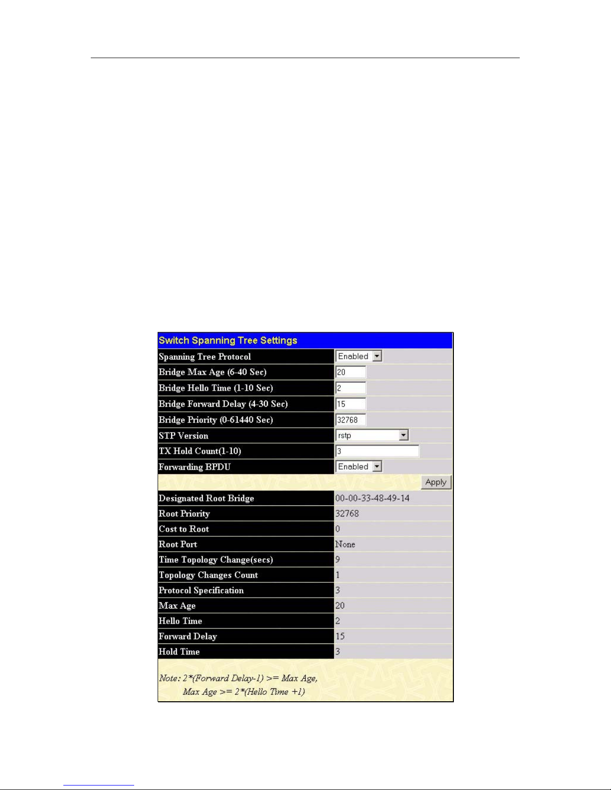
D-Link DGS-3324SR Layer 3 Stackable Gigabit Ethernet Switch
40
designated as edge ports transition to a forwarding state immediately without going through the listening and
learning states. An edge port loses its status if it receives a BPDU packet, immediately becoming a normal
spanning tree port.
P2P Port
A P2P port is also capable of rapid transition. P2P ports may be used to connect to other bridges. Under RSTP,
all ports operating in full-duplex mode are considered to be P2P ports, unless manually overridden through
configuration.
802.1d/802.1w Compatibility
RSTP can interoperate with legacy equipment and is capable of automatically adjusting BPDU packets to 802.1d
format when necessary. However, any segment using 802.1 STP will not benefit from the rapid transition and
rapid topology change detection of RSTP. The protocol also provides for a variable used for migration in the
event that legacy equipment on a segment is updated to use RSTP.
STP Switch Settings
The Spanning Tree Protocol (STP) operates on two levels: on the switch level, the settings are globally
implemented. On the port level, the settings are implemented on a per user-defined Group of ports basis. To
open the following window, open the Spanning Tree folder in the Configuration menu and click the STP
Switch Settings link.
Figure 4- 13. STP Switch Settings
Page 56

D-Link DGS-3324SR Layer 3 Stackable Gigabit Ethernet Switch
41
Configure the following parameters and click the Apply button to implement them:
Parameter Description
Spanning Tree
Protocol <Disabled>
This field can be toggled between Enabled and Disabled using the pulldown menu. This will enable or disable the Spanning Tree Protocol (STP),
globally, for the switch.
Bridge Max Age: (6 40 sec) <20 >
The Max. Age can be set from 6 to 40 seconds. At the end of the Max.
Age, if a BPDU has still not been received from the Root Bridge, your
Switch will start sending its own BPDU to all other Switches for permission
to become the Root Bridge. If it turns out that your Switch has the lowest
Bridge Identifier, it will become the Root Bridge.
Bridge Hello Time: (1
- 10 sec) < 2 >
The Hello Time can be set from 1 to 10 seconds. This is the interval
between two transmissions of BPDU packets sent by the Root Bridge to
tell all other Switches that it is indeed the Root Bridge.
Bridge Forward
Delay: (4 - 30 sec)
<15 >
The Forward Delay can be from 4 to 30 seconds. This is the time any port
on the Switch spends in the listening state while moving from the blocking
state to the forwarding state.
Bridge Priority: (0 -
61440) <32768>
A Priority for the switch can be set from 0 to 61440. This number is used
in the voting process between switches on the network to determine which
switch will be the root switch. A low number indicates a high priority, and a
high probability that this switch will be elected as the root switch.
STP Version<RSTP >
Choose RSTP (default) or STP Compatibility. Both versions use STP
parameters in the same way. RSTP is fully compatible with IEEE 802.1d
STP and will function with legacy equipment.
Tx Hold Count <3 >
This is the maximum number of Hello packets transmitted per interval. The
count can be specified from 1 to 10. Default value = 3.
Forwarding BPDU
<Enabled >
This field can enabled or disabled. When it is enabled it allows the
forwarding of STP BPDU packets from other network devices when STP is
disabled on the switch. The default is enabled.
Click Apply to implement the changes made.
Note: The Hello Time cannot be longer than the Max. Age. Otherwise, a
configuration error will occur.
Observe the following formulas when setting the above parameters:
Max. Age ≤ 2 x (Forward Delay - 1 second)
Max. Age ≥ 2 x (Hello Time + 1 second)
STP Port Settings
For stacked switch installations, first select the Unit to be configured.
Page 57
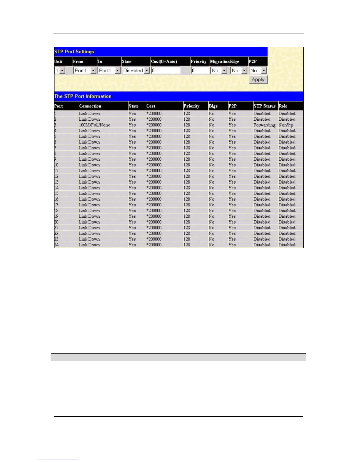
D-Link DGS-3324SR Layer 3 Stackable Gigabit Ethernet Switch
42
Figure 4- 14. STP Port Settings
In addition to setting Spanning Tree parameters for use on the switch level, the Switch allows for the
configuration of groups of ports, each port-group of which will have its own spanning tree, and will require some
of its own configuration settings. An STP Group will use the switch-level parameters entered above, with the
addition of Port Priority and Port Cost.
An STP Group spanning tree works in the same way as the switch-level spanning tree, but the root bridge
concept is replaced with a root port concept. A root port is a port of the group that is elected on the basis of port
priority and port cost, to be the connection to the network for the group. Redundant links will be blocked, just as
redundant links are blocked on the switch level.
The STP on the switch level blocks redundant links between switches (and similar network devices). The port
level STP will block redundant links within an STP Group.
It is advisable to define an STP Group to correspond to a VLAN group of ports.
The following fields can be set:
Parameter Description
Unit
This is the Unit ID of a switch in a switch stack.
From/To < Port 1 >
A consecutive group of ports may be configured starting with the selected
port.
State < Disabled >
This drop-down menu allows you to Enable or Disable STP for the
selected group of ports.
Page 58
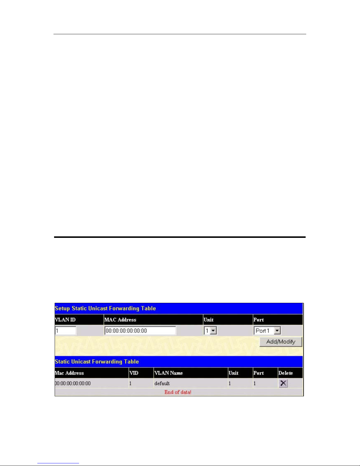
D-Link DGS-3324SR Layer 3 Stackable Gigabit Ethernet Switch
43
Cost(0=Auto) < 0 >
A Port Cost can be set from 1 to 200000000. The lower the number, the
greater the probability the port will be chosen to forward packets.
Default port cost:
100Mbps port = 200000
Gigabit ports = 20000
Priority <0>
A Port Priority can be from 0 to 240. The lower the number, the greater the
probability the port will be chosen as the Root Port.
Migration <No>
Select Yes or No. Choosing Yes will enable the port to migrate from 802.1d
STP status to 802.1w RSTP status. RSTP can coexist with standard STP,
however the benefits of RSTP are not realized on a port where an 802.1d
network connects to an 802.1w enabled network. Migration should be
enabled (yes) on ports connected to network stations or segments that will
be upgraded to 802.1w RSTP on all or some portion of the segment.
Edge <No>
Select Yes or No. Choosing Yes designates the port as an edge port. Edge
ports cannot create loops, however an edge port can lose edge port status
if a topology change creates a potential for a loop. An edge port normally
should not receive BPDU packets. If a BPDU packet is received it
automatically loses edge port status. No indicates the port does not have
edge port status.
P2P <No>
Select Yes or No. Choosing Yes indicates a point-to-point (p2p) shared
link. These are similar to edge ports however they are restricted in that a
p2p port must operate in full duplex. Like edge ports, p2p ports transition to
a forwarding state rapidly thus benefiting from RSTP.
Click Apply to implement the changes made.
Configuring Forwarding & Filtering
Static Unicast Forwarding
Open the Forwarding & Filtering folder in the Configuration menu and click on the Unicast Forwarding
link. This will open the Setup Static Unicast Forwarding Table, as shown below:
Figure 4- 15. Setup Static Unicast Forwarding Table and Static Unicast Forwarding Table
To add or edit an entry, define the following parameters and then click Add/Modify:
Page 59
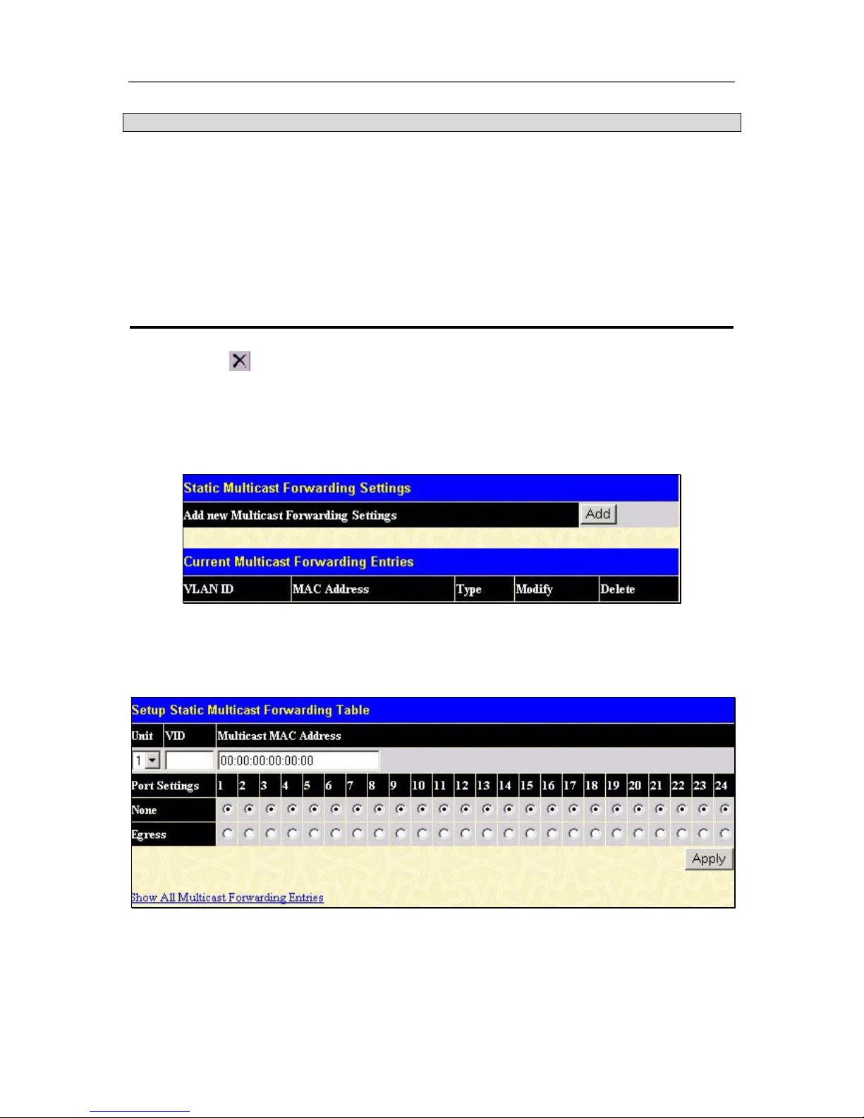
D-Link DGS-3324SR Layer 3 Stackable Gigabit Ethernet Switch
44
Parameter Description
VLAN ID (VID)
The VLAN ID number of the VLAN on which the above Unicast MAC
address resides.
MAC Address
The MAC address to which packets will be statically forwarded. This must
be a unicast MAC address.
Unit
Allows the designation of the module on which the above MAC address
resides.
Port
Allows the selection of the port number on which the MAC address entered
above resides.
Click Apply to implement the changes made. To delete an entry in the Static Unicast Forwarding Table, click
the corresponding
under the Delete heading.
Static Multicast Forwarding
The following figure and table describe how to set up Multicast forwarding on the switch. Open the Forwarding
& Filtering folder and click on the Multicast Forwarding link to see the entry screen below:
Figure 4- 16. Static Multicast Forwarding Settings and Current Multicast Forwarding Entries
The Static Multicast Forwarding Settings page displays all of the entries made into the Switch’s static
multicast forwarding table. Click the Add button to open the Setup Static Multicast Forwarding Table, as
shown below:
Figure 4- 17. Setup Static Multicast Forwarding Table
The following parameters can be set:
Page 60

D-Link DGS-3324SR Layer 3 Stackable Gigabit Ethernet Switch
45
Parameter Description
Unit
This is the Unit ID of a switch in a switch stack.
VID
The VLAN ID of the VLAN the corresponding MAC address belongs to.
Multicast MAC
Address
The MAC address of the static source of multicast packets. This must be a
multicast MAC address.
Port Settings
Allows the selection of ports that will be members of the static multicast
group and ports that are either forbidden from joining dynamically, or that
can join the multicast group dynamically, using GMRP.
The options are:
None – no restrictions on the port dynamically joining the multicast group.
When None is chosen, the port will not be a member of the Static Multicast
Group.
Egress – the port is a static member of the multicast group.
Click Apply to implement the changes made. To delete an entry in the Static Multicast Forwarding Table, click
the corresponding
under the Delete heading. Click the Show All Multicast Forwarding Entries link to return
to the Static Multicast Forwarding Settings window.
Configuring VLANs
Understanding IEEE 802.1p Priority
Priority tagging is a function defined by the IEEE 802.1p standard designed to provide a means of managing
traffic on a network where many different types of data may be transmitted simultaneously. It is intended to
alleviate problems associated with the delivery of time critical data over congested networks. The quality of
applications that are dependent on such time critical data, such as video conferencing, can be severely and
adversely affected by even very small delays in transmission.
Network devices that are in compliance with the IEEE 802.1p standard have the ability to recognize the priority
level of data packets. These devices can also assign a priority label or tag to packets. Compliant devices can also
strip priority tags from packets. This priority tag determines the packet’s degree of expeditiousness and
determines the queue to which it will be assigned.
Priority tags are given values from 0 to 7 with 0 being assigned to the lowest priority data and 7 assigned to the
highest. The highest priority tag 7 is generally only used for data associated with video or audio applications,
which are sensitive to even slight delays, or for data from specified end users whose data transmissions warrant
special consideration.
The Switch allows you to further tailor how priority tagged data packets are handled on your network. Using
queues to manage priority tagged data allows you to specify its relative priority to suit the needs of your network.
There may be circumstances where it would be advantageous to group two or more differently tagged packets
into the same queue. Generally, however, it is recommended that the highest priority queue, Queue 1, be
reserved for data packets with a priority value of 7. Packets that have not been given any priority value are
placed in Queue 0 and thus given the lowest priority for delivery.
A weighted round robin system is employed on the Switch to determine the rate at which the queues are emptied
of packets. The ratio used for clearing the queues is 4:1. This means that the highest priority queue, Queue 1, will
clear 4 packets for every 1 packet cleared from Queue 0.
Page 61

D-Link DGS-3324SR Layer 3 Stackable Gigabit Ethernet Switch
46
Remember, the priority queue settings on the Switch are for all ports, and all devices connected to the Switch
will be affected. This priority queuing system will be especially beneficial if your network employs switches
with the capability of assigning priority tags.
VLANs
A Virtual Local Area Network (VLAN) is a network topology configured according to a logical scheme rather
than the physical layout. VLANs can be used to combine any collection of LAN segments into an autonomous
user group that appears as a single LAN. VLANs also logically segment the network into different broadcast
domains so that packets are forwarded only between ports within the VLAN. Typically, a VLAN corresponds to
a particular subnet, although not necessarily.
VLANs can enhance performance by conserving bandwidth, and improve security by limiting traffic to specific
domains.
A VLAN is a collection of end nodes grouped by logic instead of physical location. End nodes that frequently
communicate with each other are assigned to the same VLAN, regardless of where they are physically on the
network. Logically, a VLAN can be equated to a broadcast domain, because broadcast packets are forwarded to
only members of the VLAN on which the broadcast was initiated.
Notes About VLANs on the DGS-3324SR
No matter what basis is used to uniquely identify end nodes and assign these nodes VLAN membership, packets
cannot cross VLANs without a network device performing a routing function between the VLANs.
The DGS-3324SR supports IEEE 802.1Q VLANs and Port-Based VLANs. The port untagging function can be
used to remove the 802.1Q tag from packet headers to maintain compatibility with devices that are tag-unaware.
The Switch’s default is to assign all ports to a single 802.1Q VLAN named “default.”
The “default” VLAN has a VID = 1.
The member ports of Port-based VLANs may overlap, if desired.
IEEE 802.1Q VLANs
Some relevant terms:
Tagging – The act of putting 802.1Q VLAN information into the header of a packet.
Untagging – The act of stripping 802.1Q VLAN information out of the packet header.
Ingress port – A port on a switch where packets are flowing into the switch and VLAN decisions must be made.
Egress port – A port on a switch where packets are flowing out of the switch, either to another switch or to an
end station, and tagging decisions must be made.
IEEE 802.1Q (tagged) VLANs are implemented on the Switch. 802.1Q VLANs require tagging, which enables
them to span the entire network (assuming all switches on the network are IEEE 802.1Q-compliant).
VLANs allow a network to be segmented in order to reduce the size of broadcast domains. All packets entering a
VLAN will only be forwarded to the stations (over IEEE 802.1Q enabled switches) that are members of that
VLAN, and this includes broadcast, multicast and unicast packets from unknown sources.
VLANs can also provide a level of security to your network. IEEE 802.1Q VLANs will only deliver packets
between stations that are members of the VLAN.
Page 62
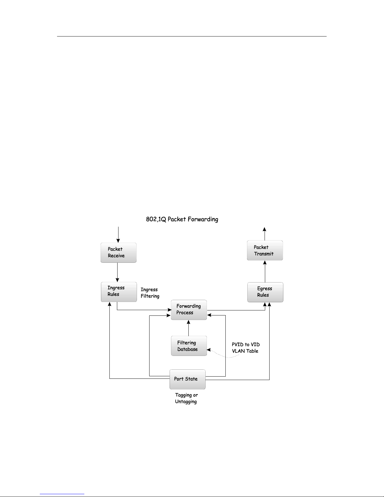
D-Link DGS-3324SR Layer 3 Stackable Gigabit Ethernet Switch
47
Any port can be configured as either tagging or untagging. The untagging feature of IEEE 802.1Q VLANs
allows VLANs to work with legacy switches that don’t recognize VLAN tags in packet headers. The tagging
feature allows VLANs to span multiple 802.1Q-compliant switches through a single physical connection and
allows Spanning Tree to be enabled on all ports and work normally.
The IEEE 802.1Q standard restricts the forwarding of untagged packets to the VLAN the receiving port is a
member of.
The main characteristics of IEEE 802.1Q are as follows:
• Assigns packets to VLANs by filtering.
• Assumes the presence of a single global spanning tree.
• Uses an explicit tagging scheme with one-level tagging.
802.1Q VLAN Packet Forwarding
Packet forwarding decisions are made based upon the following three types of rules:
• Ingress rules – rules relevant to the classification of received frames belonging to a VLAN.
• Forwarding rules between ports – decides whether to filter or forward the packet.
• Egress rules – determines if the packet must be sent tagged or untagged.
Figure 4- 18. IEEE 802.1Q Packet Forwarding
802.1Q VLAN Tags
The figure below shows the 802.1Q VLAN tag. There are four additional octets inserted after the source MAC
address. Their presence is indicated by a value of 0x8100 in the EtherType field. When a packet’s EtherType
Page 63
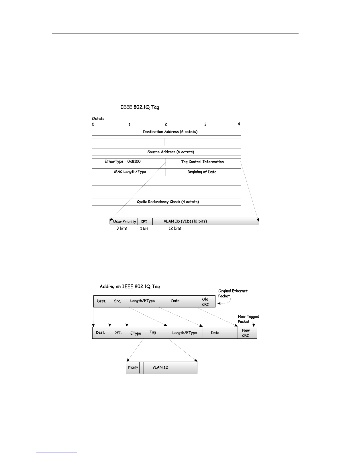
D-Link DGS-3324SR Layer 3 Stackable Gigabit Ethernet Switch
48
field is equal to 0x8100, the packet carries the IEEE 802.1Q/802.1p tag. The tag is contained in the following
two octets and consists of 3 bits of user priority, 1 bit of Canonical Format Identifier (CFI – used for
encapsulating Token Ring packets so they can be carried across Ethernet backbones), and 12 bits of VLAN ID
(VID). The 3 bits of user priority are used by 802.1p. The VID is the VLAN identifier and is used by the 802.1Q
standard. Because the VID is 12 bits long, 4094 unique VLANs can be identified.
The tag is inserted into the packet header making the entire packet longer by 4 octets. All of the information
originally contained in the packet is retained.
Figure 4- 19. IEEE 802.1Q Tag
The EtherType and VLAN ID are inserted after the MAC source address, but before the original
EtherType/Length or Logical Link Control. Because the packet is now a bit longer than it was originally, the
Cyclic Redundancy Check (CRC) must be recalculated.
Figure 4- 20. Adding an IEEE 802.1Q Tag
Page 64

D-Link DGS-3324SR Layer 3 Stackable Gigabit Ethernet Switch
49
Port VLAN ID
Packets that are tagged (are carrying the 802.1Q VID information) can be transmitted from one 802.1Q
compliant network device to another with the VLAN information intact. This allows 802.1Q VLANs to span
network devices (and indeed, the entire network, if all network devices are 802.1Q compliant).
Unfortunately, not all network devices are 802.1Q compliant. These devices are referred to as tag-unaware.
802.1Q devices are referred to as tag-aware.
Prior to the adoption of 802.1Q VLANs, port-based and MAC-based VLANs were in common use. These
VLANs relied upon a Port VLAN ID (PVID) to forward packets. A packet received on a given port would be
assigned that port’s PVID and then be forwarded to the port that corresponded to the packet’s destination address
(found in the Switch’s forwarding table). If the PVID of the port that received the packet is different from the
PVID of the port that is to transmit the packet, the Switch will drop the packet.
Within the Switch, different PVIDs mean different VLANs (remember that two VLANs cannot communicate
without an external router). So, VLAN identification based upon the PVIDs cannot create VLANs that extend
outside a given switch (or switch stack).
Every physical port on a switch has a PVID. 802.1Q ports are also assigned a PVID, for use within the Switch. If
no VLANs are defined on the Switch, all ports are then assigned to a default VLAN with a PVID equal to 1.
Untagged packets are assigned the PVID of the port on which they were received. Forwarding decisions are
based upon this PVID, in so far as VLANs are concerned. Tagged packets are forwarded according to the VID
contained within the tag. Tagged packets are also assigned a PVID, but the PVID is not used to make packet
forwarding decisions, the VID is.
Tag-aware switches must keep a table to relate PVIDs within the Switch to VIDs on the network. The Switch
will compare the VID of a packet to be transmitted to the VID of the port that is to transmit the packet. If the two
VIDs are different, the switch will drop the packet. Because of the existence of the PVID for untagged packets
and the VID for tagged packets, tag-aware and tag-unaware network devices can coexist on the same network.
A switch port can have only one PVID, but can have as many VIDs as the Switch has memory in its VLAN table
to store them.
Because some devices on a network may be tag-unaware, a decision must be made at each port on a tag-aware
device before packets are transmitted – should the packet to be transmitted have a tag or not? If the transmitting
port is connected to a tag-unaware device, the packet should be untagged. If the transmitting port is connected to
a tag-aware device, the packet should be tagged.
Tagging and Untagging
Every port on an 802.1Q compliant switch can be configured as tagging or untagging.
Ports with tagging enabled will put the VID number, priority and other VLAN information into the header of all
packets that flow into and out of it. If a packet has previously been tagged, the port will not alter the packet, thus
keeping the VLAN information intact. The VLAN information in the tag can then be used by other 802.1Q
compliant devices on the network to make packet-forwarding decisions.
Ports with untagging enabled will strip the 802.1Q tag from all packets that flow into and out of those ports. If
the packet doesn’t have an 802.1Q VLAN tag, the port will not alter the packet. Thus, all packets received by
and forwarded by an untagging port will have no 802.1Q VLAN information. (Remember that the PVID is only
used internally within the switch). Untagging is used to send packets from an 802.1Q-compliant network device
to a non-compliant network device.
Page 65

D-Link DGS-3324SR Layer 3 Stackable Gigabit Ethernet Switch
50
Ingress Filtering
A port on a switch where packets are flowing into the switch and VLAN decisions must be made is referred to as
an ingress port. If ingress filtering is enabled for a port, the switch will examine the VLAN information in the
packet header (if present) and decide whether or not to forward the packet.
If the packet is tagged with VLAN information, the ingress port will first determine if the ingress port itself is a
member of the tagged VLAN. If it is not, the packet will be dropped. If the ingress port is a member of the
802.1Q VLAN, the switch then determines if the destination port is a member of the 802.1Q VLAN. If it is not,
the packet is dropped. If the destination port is a member of the 802.1Q VLAN, the packet is forwarded and the
destination port transmits it to its attached network segment.
If the packet is not tagged with VLAN information, the ingress port will tag the packet with its own PVID as a
VID (if the port is a tagging port). The switch then determines if the destination port is a member of the same
VLAN (has the same VID) as the ingress port. If it does not, the packet is dropped. If it has the same VID, the
packet is forwarded and the destination port transmits it on its attached network segment.
This process is referred to as ingress filtering and is used to conserve bandwidth within the Switch by dropping
packets that are not on the same VLAN as the ingress port at the point of reception. This eliminates the
subsequent processing of packets that will just be dropped by the destination port.
Default VLANs
The Switch initially configures one VLAN, VID = 1, called “default.” The factory default setting assigns all
ports on the Switch to the “default.” As new VLANs are configured in Port-based mode, their respective member
ports are removed from the “default.”
Packets cannot cross VLANs. If a member of one VLAN wants to connect to another VLAN, the link must be
through an external router.
Note: If no VLANs are configured on the Switch, then all packets will be
forwarded to any destination port. Packets with unknown source
addresses will be flooded to all ports. Broadcast and multicast packets will
also be flooded to all ports.
An example is presented below:
VLAN Name VID Switch Ports
System (default) 1 5, 6, 7, 8, 21, 22, 23, 24
Engineering 2 9, 10, 11, 12
Marketing 3 13, 14, 15, 16
Finance 4 17, 18, 19, 20
Sales 5 1, 2, 3, 4
Table 4- 2. VLAN Example – Assigned Ports
Port-based VLANs
Port-based VLANs limit traffic that flows into and out of switch ports. Thus, all devices connected to a port are
members of the VLAN(s) the port belongs to, whether there is a single computer directly connected to a switch,
or an entire department.
Page 66
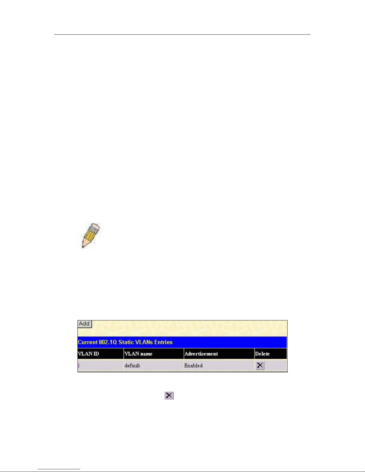
D-Link DGS-3324SR Layer 3 Stackable Gigabit Ethernet Switch
51
On port-based VLANs, NICs do not need to be able to identify 802.1Q tags in packet headers. NICs send and
receive normal Ethernet packets. If the packet’s destination lies on the same segment, communications take place
using normal Ethernet protocols. Even though this is always the case, when the destination for a packet lies on
another switch port, VLAN considerations come into play to decide if the packet gets dropped by the switch or
delivered.
VLAN Segmentation
Take for example a packet that is transmitted by a machine on Port 1 that is a member of VLAN 2. If the
destination lies on another port (found through a normal forwarding table lookup), the switch then looks to see if
the other port (Port 10) is a member of VLAN 2 (and can therefore receive VLAN 2 packets). If Port 10 is not a
member of VLAN 2, then the packet will be dropped by the switch and will not reach its destination. If Port 10 is
a member of VLAN 2, the packet will go through. This selective forwarding feature based on VLAN criteria is
how VLANs segment networks. The key point being that Port 1 will only transmit on VLAN 2.
Network resources such as printers and servers however, can be shared across VLANs. This is achieved by
setting up overlapping VLANs. That is ports can belong to more than one VLAN group. For example, setting
VLAN 1 members to ports 1, 2, 3, and 4 and VLAN 2 members to ports 1, 5, 6, and 7. Port 1 belongs to two
VLAN groups. Ports 8, 9, and 10 are not configured to any VLAN group. This means ports 8, 9, and 10 are in the
same VLAN group.
VLAN and Trunk Groups
The members of a trunk group have the same VLAN setting. Any VLAN setting on the members of a trunk
group will apply to the other member ports.
Note: In order to use VLAN segmentation in conjunction with port trunk
groups, you can first set the port trunk group(s), and then you may
configure VLAN settings. If you wish to change the port trunk grouping
with VLANs already in place, you will not need to reconfigure the VLAN
settings after changing the port trunk group settings. VLAN settings will
automatically change in conjunction with the change of the port trunk
group settings.
Configuring Static VLANs
To create or modify an 802.1Q VLAN:
In the Configuration folder, open the VLAN folder and click the Static VLAN Entry link to open the following
window:
Figure 4- 21. Current 802.1Q Static VLANs Entries window
The 802.1Q Static VLANs menu lists all previously configured VLANs by VLAN ID and name. To delete an
existing 802.1Q VLAN, click the corresponding
button under the Delete heading.
To create a new 802.1Q VLAN, click the Add button in the Static VLANs menu. A new menu will appear, as
shown below, to configure the port settings and to assign a unique name and number to the new VLAN. See the
table below for a description of the parameters in the new menu.
Page 67
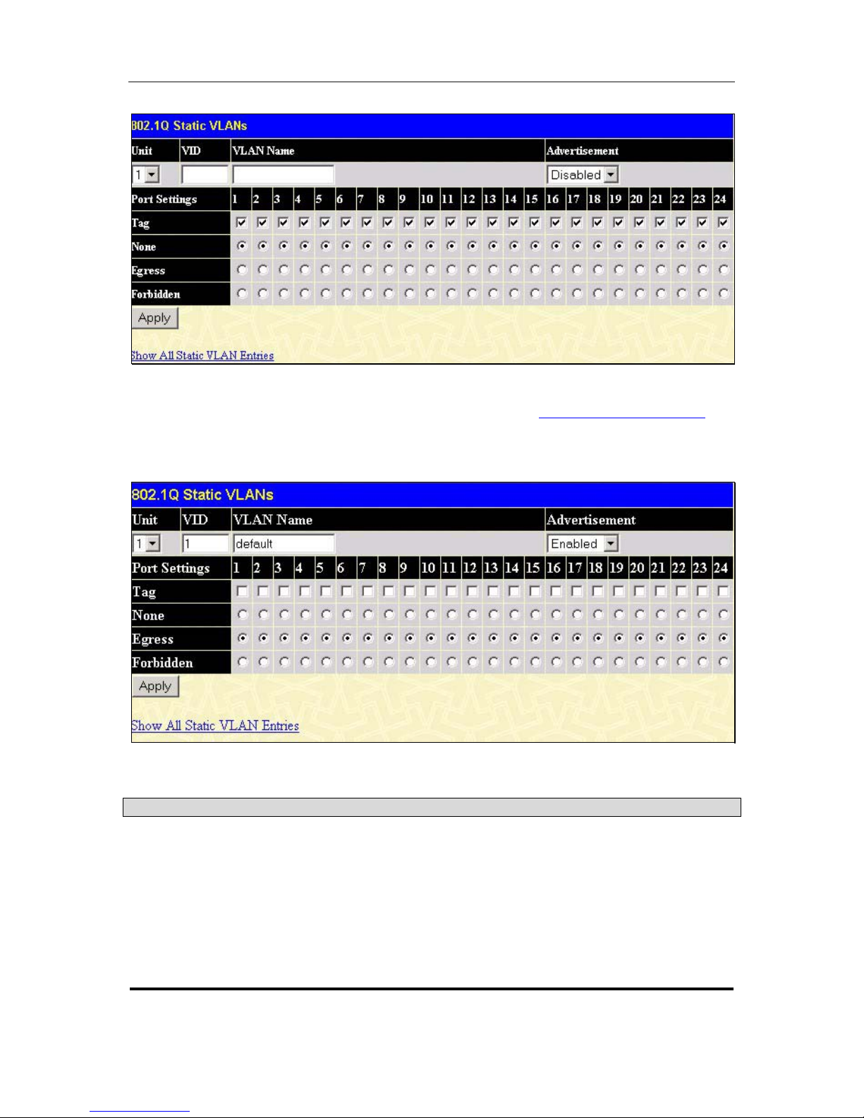
D-Link DGS-3324SR Layer 3 Stackable Gigabit Ethernet Switch
52
Figure 4- 22. 802.1Q Static VLANs – Add
To return to the Current 802.1Q Static VLANs Entries window, click the Show All Static VLAN Entries
link.
To change an existing 802.1Q VLAN entry, double-click on the selected entry in the Current 802.1Q Static
VLANs Entries menu. A new menu appears, use this to configure the port settings and to assign a unique name
and number to the new VLAN. See the table below for a description of the parameters in the new menu.
Figure 4- 23. 802.1Q Static VLANs Entry Settings – Modify
The following fields can then be set in either the Add or Modify 802.1Q Static VLANs menus:
Parameter Description
Unit
Displays the Unit ID of the switch − within the switch stack − that the VLAN
will be created on.
VID (VLAN ID) Allows the entry of a VLAN ID in the Add dialog box, or displays the VLAN
ID of an existing VLAN in the Edit dialog box. VLANs can be identified by
either the VID or the VLAN name.
VLAN Name
Allows the entry of a name for the new VLAN in the Add dialog box, or for
editing the VLAN name in the Edit dialog box.
Page 68

D-Link DGS-3324SR Layer 3 Stackable Gigabit Ethernet Switch
53
Advertisement
Enabling this function will allow the switch to send out GVRP packets to
outside sources, notifying that they may join the existing VLAN.
Port
Allows an individual port to be specified as member of a VLAN.
Tag
Specifies the port as either 802.1Q tagging or 802.1Q untagged. Checking
the box will designate the port as Tagged.
None
Allows an individual port to be specified as a non-VLAN member.
Egress
Select this to specify the port as a static member of the VLAN. Egress
member ports are ports that will be transmitting traffic for the VLAN. These
ports can be either tagged or untagged.
Forbidden
Select this to specify the port as not being a member of the VLAN and that
the port is forbidden from becoming a member of the VLAN dynamically.
GVRP Settings
In the Configuration menu, open the VLANs folder and click GVRP Setting.
The GVRP Settings dialog box, shown below, allows you to determine whether the Switch will share its VLAN
configuration information with other GARP VLAN Registration Protocol (GVRP) enabled switches. In
addition, Ingress Checking can be used to limit traffic by filtering incoming packets whose PVID does not
match the PVID of the port. Results can be seen in the table under the configuration settings, as seen below.
Page 69
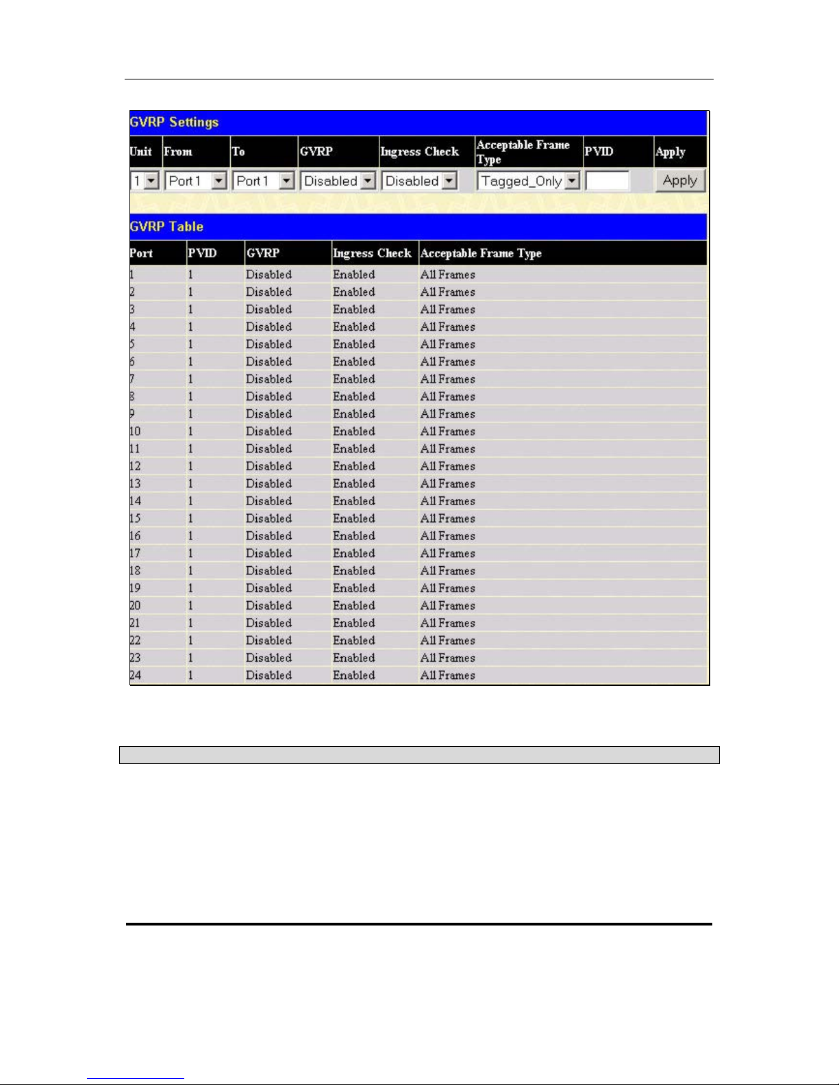
D-Link DGS-3324SR Layer 3 Stackable Gigabit Ethernet Switch
54
Figure 4- 24. GVRP Settings and GVRP Table
The following fields can be set:
Parameter Description
Unit
Displays the Unit ID of the switch − within the switch stack − that the VLAN
will be created on.
From/To
These two fields allow you to specify the range of ports that will be
included in the Port-based VLAN that you are creating using the 802.1Q
Port Settings page.
GVRP
The Group VLAN Registration Protocol (GVRP) enables the port to
dynamically become a member of a VLAN. GVRP is disabled by default.
Page 70

D-Link DGS-3324SR Layer 3 Stackable Gigabit Ethernet Switch
55
Ingress Check
This field can be toggled using the space bar between Enabled and
Disabled. Enabled enables the port to compare the VID tag of an incoming
packet with the PVID number assigned to the port. If the two are different,
the port filters (drops) the packet. Disabled disables Ingress filtering.
Ingress Checking is disabled by default.
Acceptable Frame
Type
This field denotes the type of frame that will be accepted by the port. The
user may choose between Tagged Only, which means only VLAN tagged
frames will be accepted, and Admit_All, which means both tagged and
untagged frames will be accepted. Tagged Only is enabled by default.
PVID
The read only field in the GVRP Table shows the current PVID assignment
for each port. The Switch’s default is to assign all ports to the Default
VLAN with a VID of 1.
The PVID is used by the port to tag outgoing, untagged packets, and to
make filtering decisions about incoming packets. If the port is specified to
accept only tagged frames − as tagging, and an untagged packet is
forwarded to the port for transmission, the port will add an 802.1Q tag
using the PVID to write the VID in the tag. When the packet arrives at its
destination, the receiving device will use the PVID to make VLAN
forwarding decisions.
If a packet is received by the port, and Ingress filtering is enabled, the port
will compare the VID of the incoming packet to its PVID. If the two are
unequal, the port will drop the packet. If the two are equal, the port will
receive the packet.
Configuring Traffic Control (Broadcast/Multicast Storm
Control)
Use the Traffic Control menu to enable or disable storm control and adjust the threshold for multicast and
broadcast storms, as well as DLF (Destination Look Up Failure). Traffic control settings are applied to individual
Switch modules.
Page 71
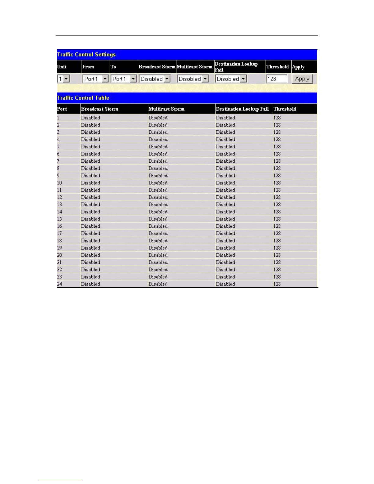
D-Link DGS-3324SR Layer 3 Stackable Gigabit Ethernet Switch
56
Figure 4- 25. Traffic Control Settings window
Traffic or storm control is used to stop broadcast, multicast or ARP request storms that may result when a loop is
created. The Destination Look Up Failure control is a method of shutting down a loop when a storm is formed
because a MAC address cannot be located in the Switch’s forwarding database and it must send a packet to all
ports or all ports on a VLAN.
To configure Traffic Control, select the Unit (Unit ID of a switch in a switch) you want to configure. Broadcast
Storm, Multicast Storm and Destination Unknown may be Enabled or Disabled. The Threshold value is the
upper threshold at which the specified traffic control is switched on. This is the number of Broadcast, Multicast
or DLF packets, in Kbps, received by the switch that will trigger the storm traffic control measures. The
Threshold value can be set from 0 to 255 packets. The Default setting is 128.
Configuring Port Security
A given port’s (or a range of ports’) dynamic MAC address learning can be locked such that the current source
MAC addresses entered into the MAC address forwarding table can not be changed once the port lock is enabled.
The port can be locked by using the Learn <Disabled> pull-down menu to Enabled, and clicking Apply.
This is a security feature that prevents unauthorized computers (with source MAC addresses unknown to the
Switch prior to locking the port (or ports) from connecting to the Switch’s locked ports and gaining access to the
network.
Page 72
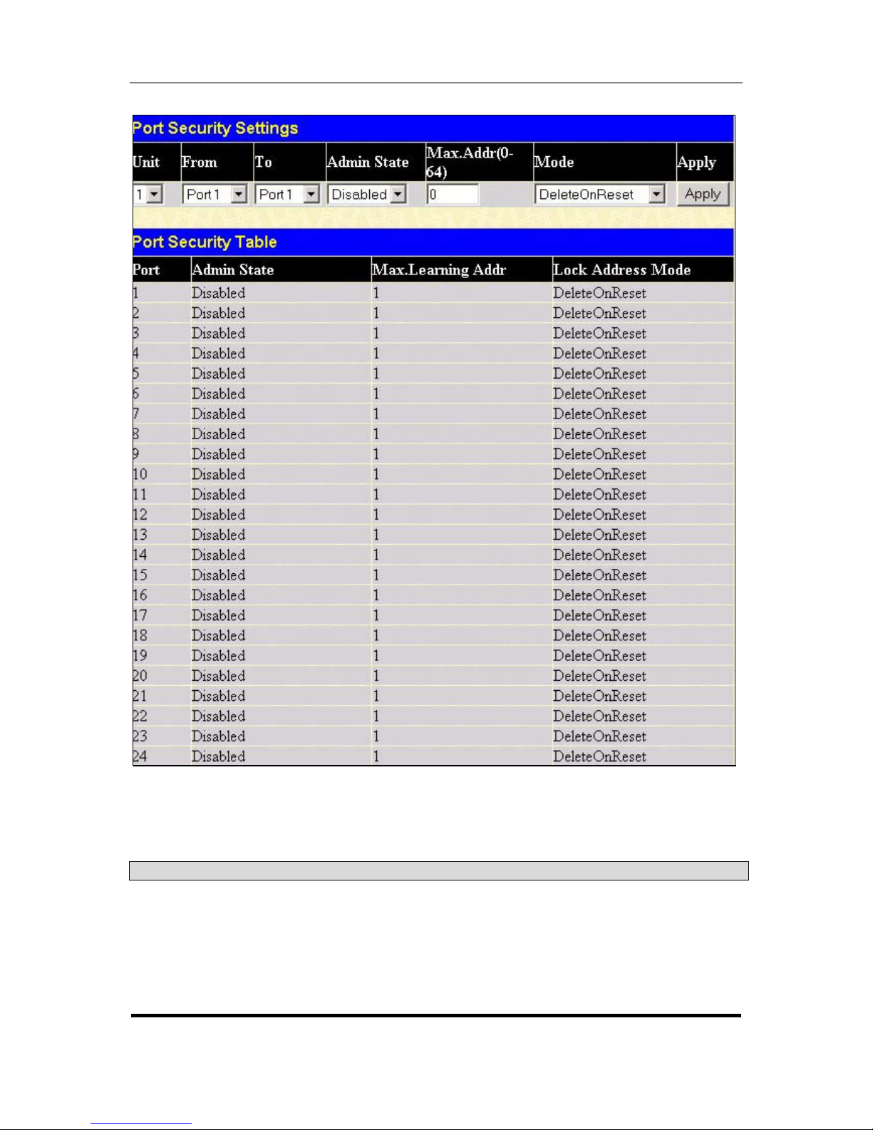
D-Link DGS-3324SR Layer 3 Stackable Gigabit Ethernet Switch
57
Figure 4- 26. Port Security Settings window
Click Apply to implement the changes on the Switch.
The following parameters can be set:
Parameter Description
Unit
Allows you to specify a switch in a switch stack using that switch’s Unit ID.
From/To
A consecutive group of ports may be configured starting with the selected
port.
Admin State
This pull-down menu allows you to Enable or Disable Port Security
(locked MAC address table for the selected ports.)
Page 73

D-Link DGS-3324SR Layer 3 Stackable Gigabit Ethernet Switch
58
Max.Addr(0-64)
The number of MAC addresses that will be in the MAC address forwarding
table for the selected switch and group of ports.
Mode
This pull-down menu allows you to select how the MAC address table
locking will be implemented on the Switch, for the selected group of ports.
The options are DeleteOnReset and DeleteOnTimeout.
Configuring QoS
Understanding QoS
The DGS-3324SR supports 802.1p priority queuing. The Switch has seven priority queues. These priority queues
are labeled as 6, the high queue to 0, the lowest queue. The eight priority tags, specified in IEEE 802.1p are
mapped to the Switch’s priority tags as follows:
• Priority 0 is assigned to the Switch’s Q2 queue.
• Priority 1 is assigned to the Switch’s Q0 queue.
• Priority 2 is assigned to the Switch’s Q1 queue.
• Priority 3 is assigned to the Switch’s Q3 queue.
• Priority 4 is assigned to the Switch’s Q4 queue.
• Priority 5 is assigned to the Switch’s Q5 queue.
• Priority 6 is assigned to the Switch’s Q6 queue.
• Priority 7 is assigned to the Switch’s Q6 queue.
For strict priority-based scheduling, any packets residing in the higher priority queues are transmitted first.
Multiple strict priority queues empty based on their priority tags. Only when these queues are empty, are packets
of lower priority transmitted.
For weighted round-robin queuing, the number of packets sent from each priority queue depends upon the
assigned weight. For a configuration of 8 CoS queues, A~H with their respective weight value: 8~1, the packets
are sent in the following sequence: A1, B1, C1, D1, E1, F1, G1, H1, A2, B2, C2, D2, E2, F2, G2, A3, B3, C3,
D3, E3, F3, A4, B4, C4, D4, E4, A5, B5, C5, D5, A6, B6, C6, A7, B7, A8, A1, B1, C1, D1, E1, F1, G1, H1.
For weighted round-robin queuing, if each CoS queue has the same weight value, then each CoS queue has an
equal opportunity to send packets just like round-robin queuing.
For weighted round-robin queuing, if the weight for a CoS is set to 0, then it will continue processing the packets
from this CoS until there are no more packets for this CoS. The other CoS queues that have been given a nonzero
value, and depending upon the weight, will follow a common weighted round-robin scheme.
Remember that the DGS-3324SR has 8 priority queues (and eight Classes of Service) for each port on the
Switch.
Setting Bandwidth Control
The bandwidth control settings are used to place a ceiling on the transmitting and receiving data rates for any
selected port. In the Configuration folder open the QoS folder and click Bandwidth Control, to view the screen
shown below.
Page 74
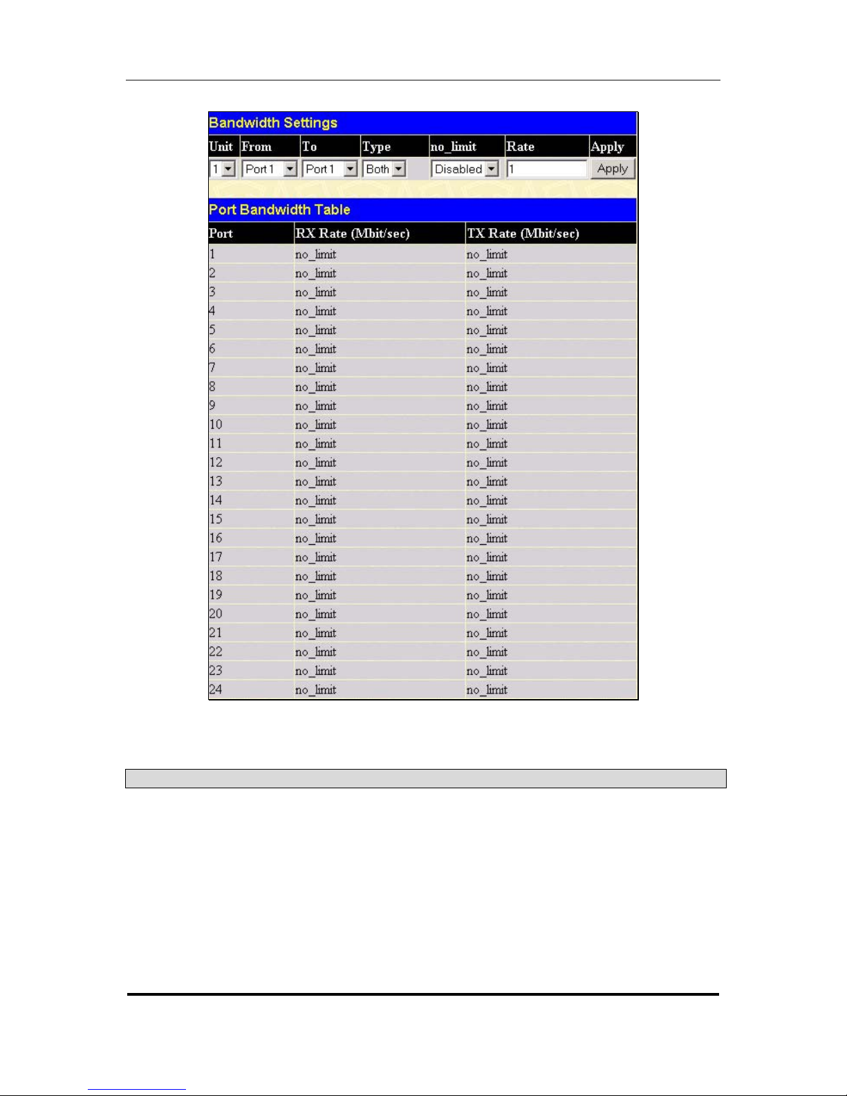
D-Link DGS-3324SR Layer 3 Stackable Gigabit Ethernet Switch
59
Figure 4- 27. Bandwidth Settings window
The following parameters can be set or are displayed:
Parameter Description
Unit
Allows you to specify a switch in a switch stack using that switch’s Unit ID.
From/To
A consecutive group of ports may be configured starting with the selected
port.
Type
This drop-down menu allows you to select between RX (receive,) TX
(transmit,) and Both. This setting will determine whether the bandwidth
ceiling is applied to receiving, transmitting, or both receiving and
transmitting packets.
no_limit
This drop-down menu allows you to specify that the selected port will have
no bandwidth limit. Enabled disables the limit.
Page 75
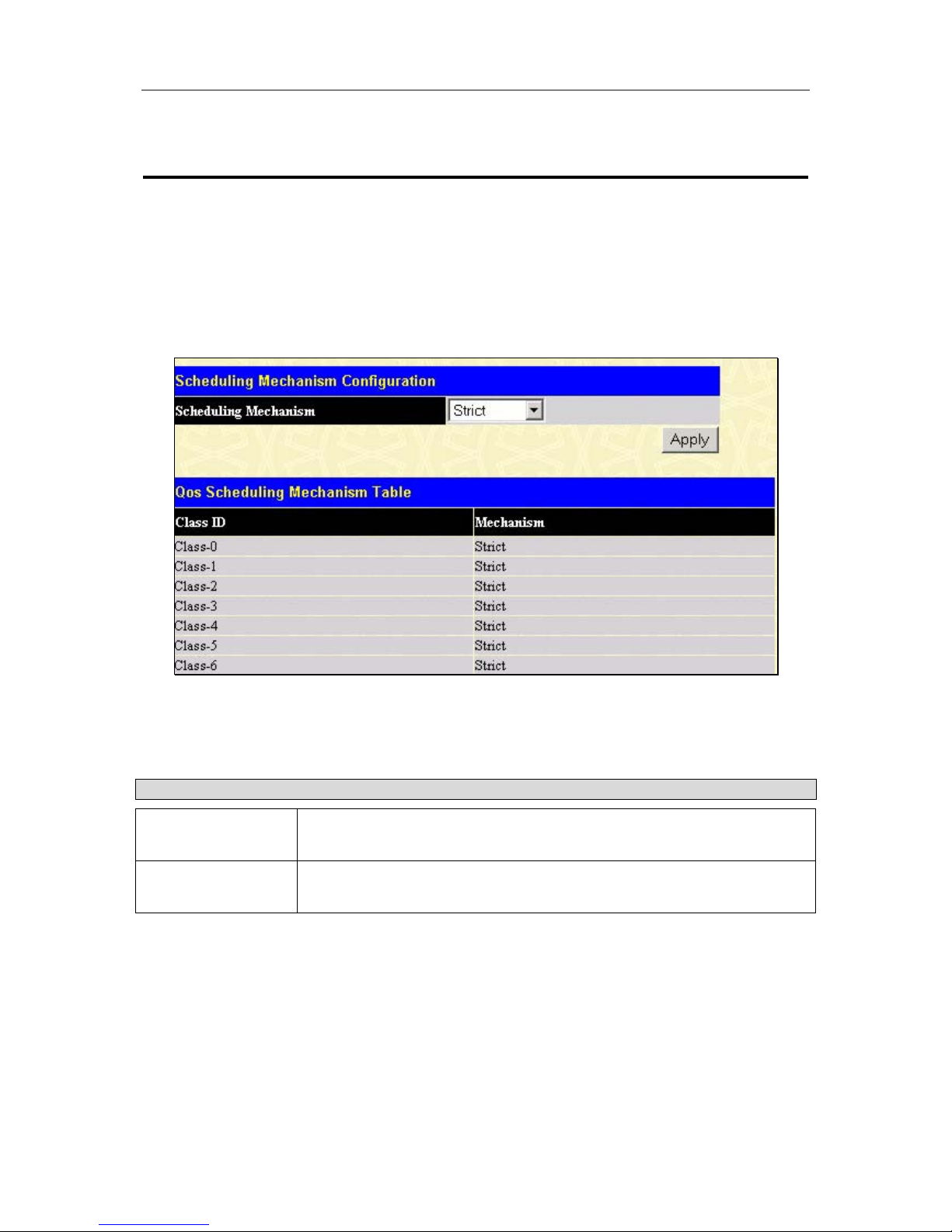
D-Link DGS-3324SR Layer 3 Stackable Gigabit Ethernet Switch
60
Rate
This field allows you to enter the data rate, in kb/s, that will be the limit for
the selected port.
Click Apply to set the Bandwidth control for the selected ports. Results of the Bandwidth Settings will be
displayed directly below, in the Port Bandwidth Table.
QoS Scheduling Mechanism Table
This drop-down menu allows you to select between a Weight Fair and a Strict mechanism for emptying the
priority queues. In the Configuration folder open the QoS folder and click QoS Scheduling Mechanism, to
view the screen shown below.
Figure 4- 28. Scheduling Mechanism Configuration window
Click Apply to let your changes take effect.
The QoS Scheduling Mechanism has the following parameters.
Parameter Description
Strict
The highest queue is the first to process traffic. That is, the highest queue
should be finished at first.
Weight fair
Use the weight fair algorithm to handle packets in an even distribution in
priority queues.
QoS Output Scheduling
QoS can be customized by changing the output scheduling used for the hardware queues in the Switch. As with
any changes to QoS implementation, careful consideration should be given to how network traffic in lower
priority queues is affected. Changes in scheduling may result in unacceptable levels of packet loss or significant
transmission delay. If you choose to customize this setting, it is important to monitor network performance,
especially during peak demand, as bottlenecks can quickly develop if the QoS settings are not suitable. In the
Configuration folder open the QoS folder and click QoS Output Scheduling, to view the screen shown below.
Page 76
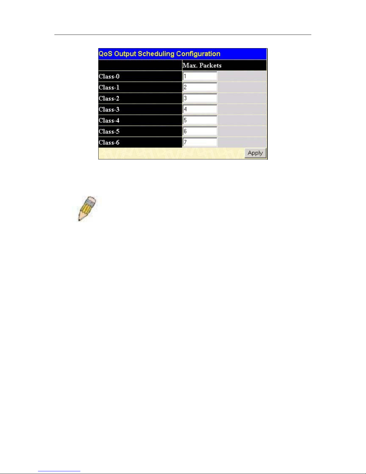
D-Link DGS-3324SR Layer 3 Stackable Gigabit Ethernet Switch
61
Figure 4- 29. QoS Output Scheduling Configuration window
Once you have assigned a priority to the port groups on the Switch, you can then assign this Class to each of the
7 levels of 802.1p priorities.
Note: The settings you assign to the queues, numbers 0-7, represent the
IEEE 802.1p priority tag number. Do not confuse these settings with port
numbers.
802.1p Default Priority
The Switch allows the assignment of a default 802.1p priority to each port on the switch. In the Configuration
folder open the QoS folder and click 802.1p Default Priority, to view the screen shown below.
Page 77
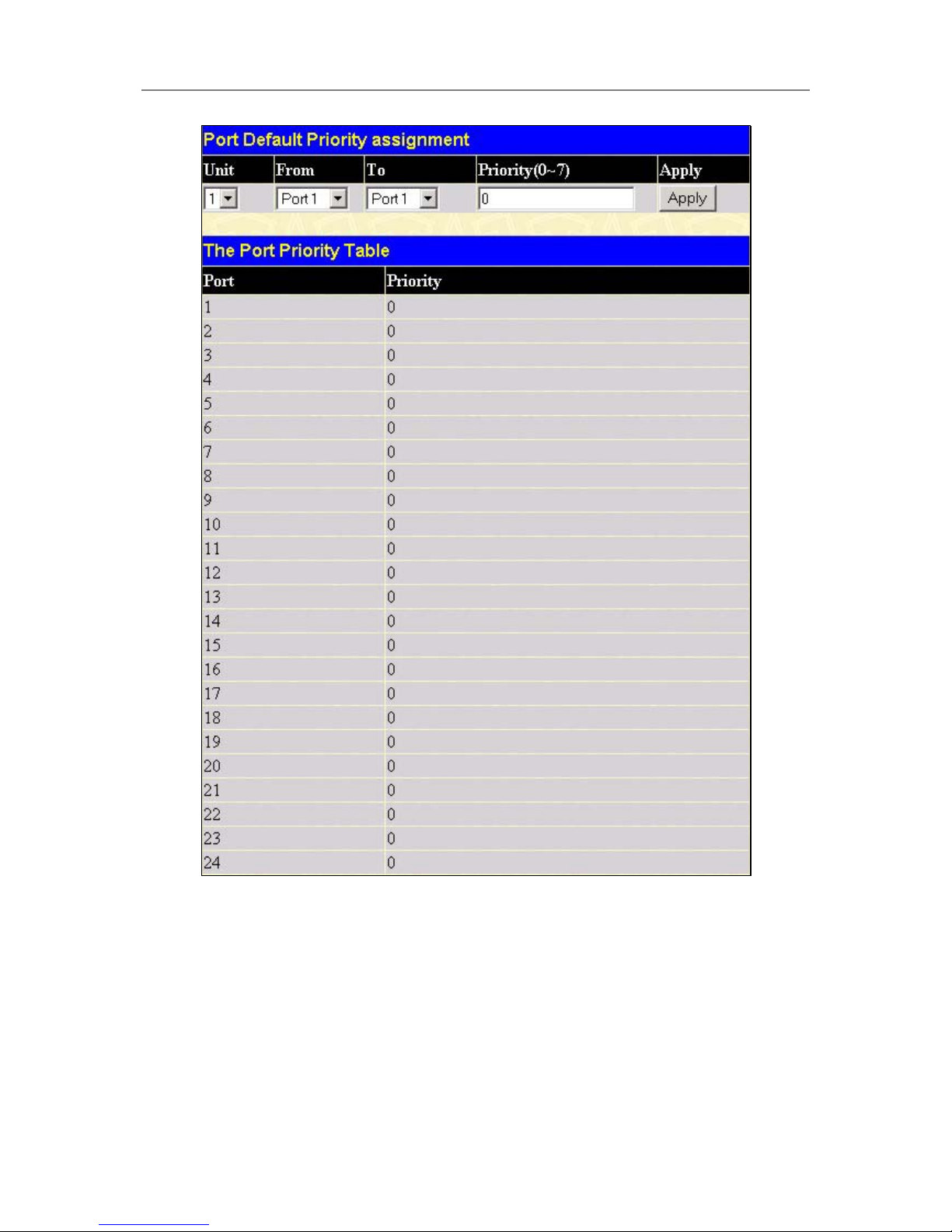
D-Link DGS-3324SR Layer 3 Stackable Gigabit Ethernet Switch
62
Figure 4- 30. 802.1p Default Priority window
This page allows you to assign a default 802.1p priority to any given port on the Switch. The priority queues are
numbered from 0 − the lowest priority − to 7 − the highest priority. Click Apply to implement your settings.
802.1p User Priority
The DGS-3324SR allows the assignment of a User Priority to each of the 802.1p priorities. In the Configuration
folder open the QoS folder and click 802.1p User Priority, to view the screen shown below.
Page 78
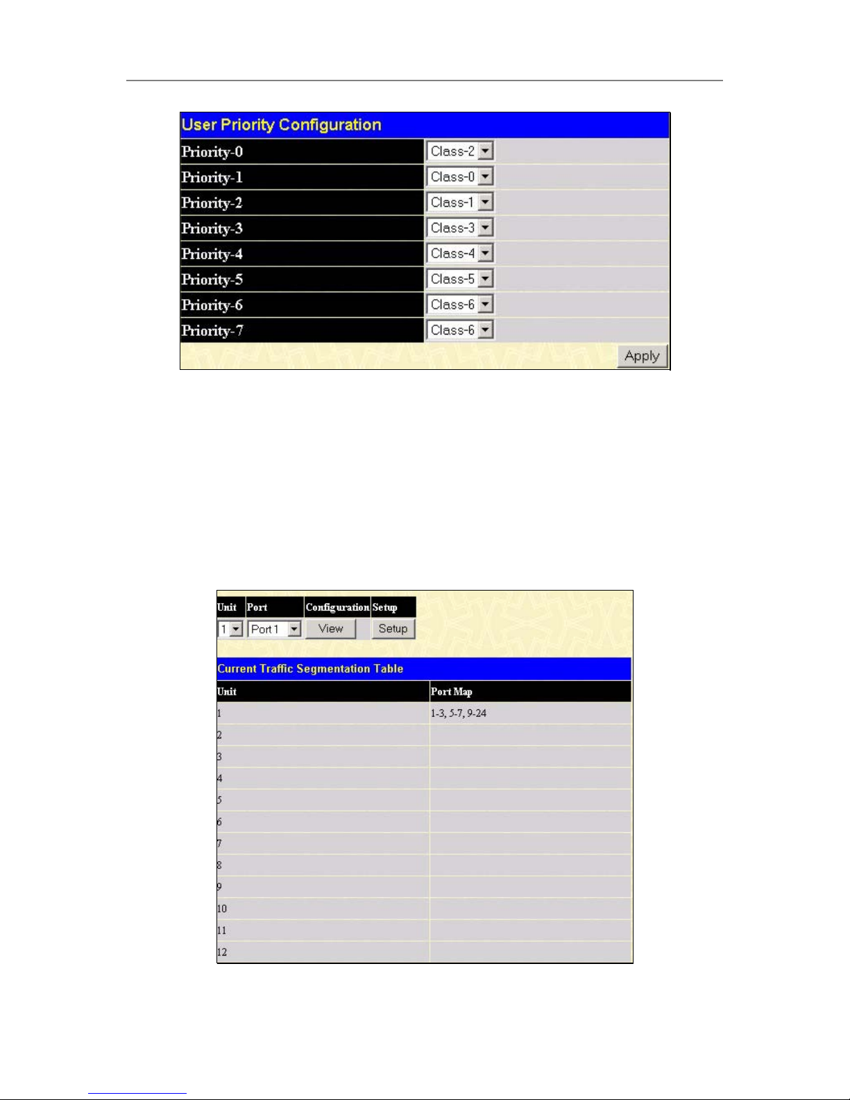
D-Link DGS-3324SR Layer 3 Stackable Gigabit Ethernet Switch
63
Figure 4- 31. User Priority Configuration window
Once you have assigned a priority to the port groups on the Switch, you can then assign this Class to each of the
8 levels of 802.1p priorities. Click Apply to set your changes.
Configuring Traffic Segmentation
Traffic segmentation is used to limit traffic flow from a single port to a group of ports on either a single switch
(in standalone mode) or a group of ports on another switch in a switch stack. This method of segmenting the flow
of traffic is similar to using VLANs to limit traffic, but is more restrictive. It provides a method of directing
traffic that does not increase the overhead of the Master switch CPU.
In the Configuration folder open the QoS folder and click Traffic Segmentation, to view the screen shown
below.
Figure 4- 32. Current Traffic Segmentation Table
Page 79
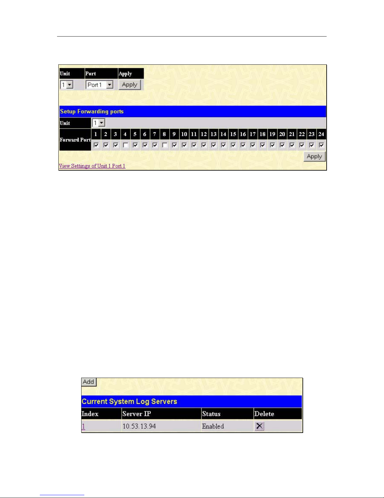
D-Link DGS-3324SR Layer 3 Stackable Gigabit Ethernet Switch
64
Click on the Setup button to open the Setup Forwarding ports page, as shown below.
Figure 4- 33. Setup Forwarding Ports window
This page allows you to determine which port on a given switch in a switch stack will be allowed to forward
packets to other ports on that switch.
Configuring traffic segmentation on the DGS-3324SR is accomplished in two parts. First you specify a switch
from a switch stack, and then a port from that switch. Then you specify a second switch from the switch stack,
and then you select which ports (or different ports on the same switch,) on that switch that you want to be able to
receive packets from the switch and port you specified in the first part.
In the example above, the switch is Unit 1 and port 1 is selected as the transmitting port. Ports 1-3, 5-7 and 9-24
are selected as being able to receive packets from port 1.
Clicking the Apply button will enter the combination of transmitting port and allowed receiving ports into the
Switch’s Traffic Segmentation table.
The Unit drop-down menu at the top of the page allows you to select a switch from a switch stack using that
switch’s Unit ID. The Port drop-down menu allows you to select a port from that switch. This is the port that
will be transmitting packets.
The Unit drop-down menu under the Setup Forwarding ports heading allows you to select a switch from a switch
stack using that switch’s Unit ID. The Forward Port click boxes allow you to select which of the ports on the
selected switch will be able to forward packets. These are the ports that will be allowed to receive packets from
the port specified above.
Click Apply to enter the settings into the Switch’s Traffic Segmentation table.
The System Log Server
The Switch can send Syslog messages to up to four designated servers using the System Log Server. In the
Configuration folder click System Log Server, to view the screen shown below.
Figure 4- 34. System Log Server window
Page 80
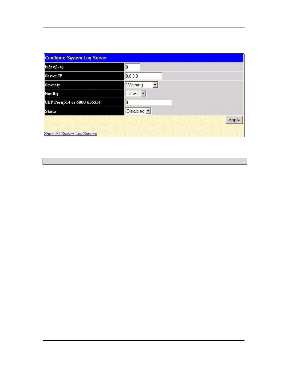
D-Link DGS-3324SR Layer 3 Stackable Gigabit Ethernet Switch
65
The parameters configured for adding and editing System Log Server settings are the same. See the table below
for a description.
Figure 4- 35. System Log Servers − Add
The following parameters can be set:
Parameter Description
Index
Syslog server settings index (1-4).
Server IP
The IP address of the Syslog server.
Severity
This drop-down menu allows you to select the level of messages that will
be sent. The options are Warning, Informational, and All.
Facility
Some of the operating system daemons and processes have been
assigned Facility values. Processes and daemons that have not been
explicitly assigned a Facility may use any of the "local use" facilities or they
may use the "user-level" Facility. Those Facilities that have been
designated are shown in the following: Bold font means the facility values
that the switch currently now.
Numerical Facility
Code
0 kernel messages
1 user-level messages
2 mail system
3 system daemons
4 security/authorization messages
5 messages generated internally by syslog line printer subsystem
7 network news subsystem
8 UUCP subsystem
9 clock daemon
10 security/authorization messages
11 FTP daemon
Page 81

D-Link DGS-3324SR Layer 3 Stackable Gigabit Ethernet Switch
66
12 NTP subsystem
13 log audit
14 log alert
15 clock daemon
16 local use 0 (local0)
17 local use 1 (local1)
18 local use 2 (local2)
19 local use 3 (local3)
20 local use 4 (local4)
21 local use 5 (local5)
22 local use 6 (local6)
23 local use 7 (local7)
UDP Port (514 or
6000-65535)
Type the UDP port number used for sending Syslog messages. The
default is 514.
Status
Choose Enabled or Disabled to activate or deactivate.
To set the System Log Server configuration, click Apply. To delete an entry from the System Log Server
window, click the corresponding
under the Delete heading of the entry you wish to delete. To return to the
Current System Log Servers window, click the Show All System Log Servers link.
Configuring SNTP Settings
The Simple Network Time Protocol (SNTP) {an adaptation of the Network Time Protocol (NPT)} is
configured on the switch using the following pages.
Time Settings
To configure the time settings for the Switch, open the Configuration folder, then the SNTP folder and click on
the Time Setting link, revealing the following screen for the user to configure.
Page 82
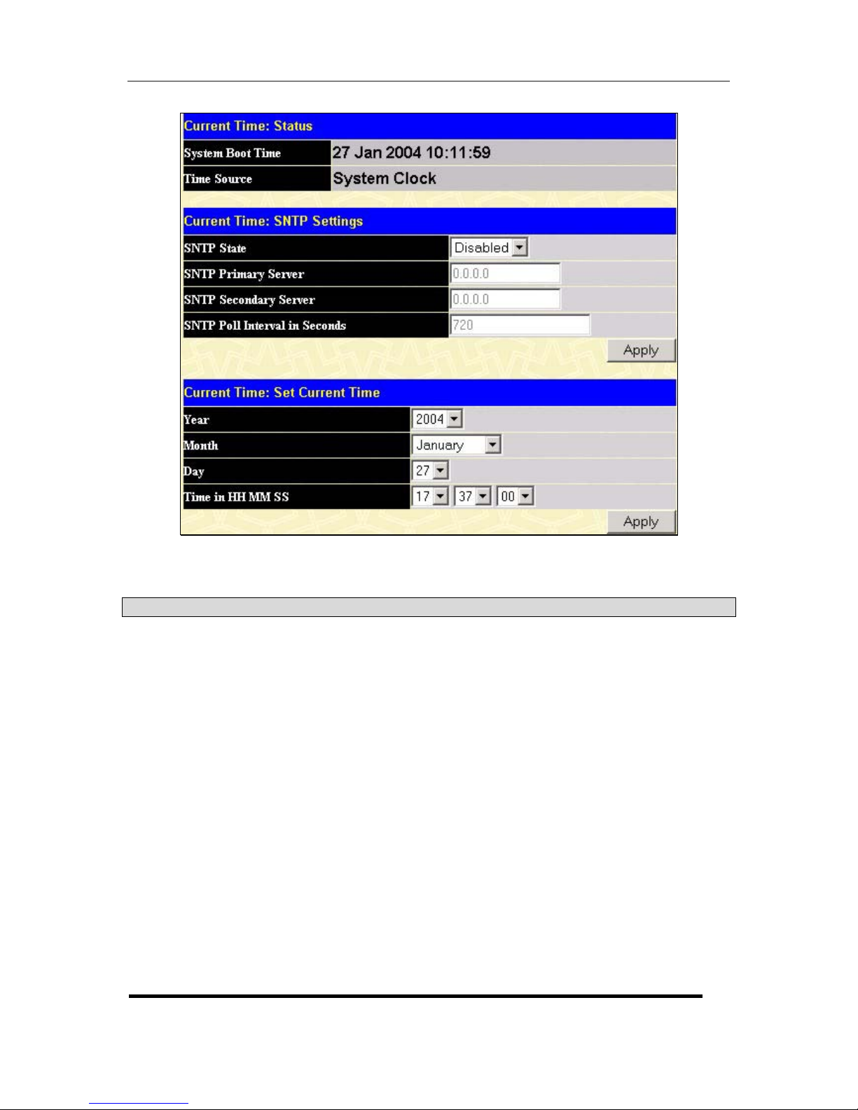
D-Link DGS-3324SR Layer 3 Stackable Gigabit Ethernet Switch
67
Figure 4- 36. Time Settings Page
The following parameters can set or are displayed:
Parameter Description
System Boot Time
Displays the time when the Switch was initially started for this session.
Time Source
Displays the time source for the system.
SNTP State
Use this pull-down menu to Enable or Disable SNTP.
SNTP Primary
Server
This is the primary server the SNTP information will be taken from.
SNTP Secondary
Server
This is the secondary server the SNTP information will be taken from.
SNTP Poll Interval in
Seconds
This is the interval, in seconds, between requests for updated SNTP
information.
Year
Enter the current year, if you want to update the system clock.
Month
Enter the current month, if you would like to update the system clock.
Day
Enter the current day, if you would like to update the system clock.
Time in HH MM SS
Enter the current time in hours, minutes and seconds if you would like
to update the system clock.
Page 83
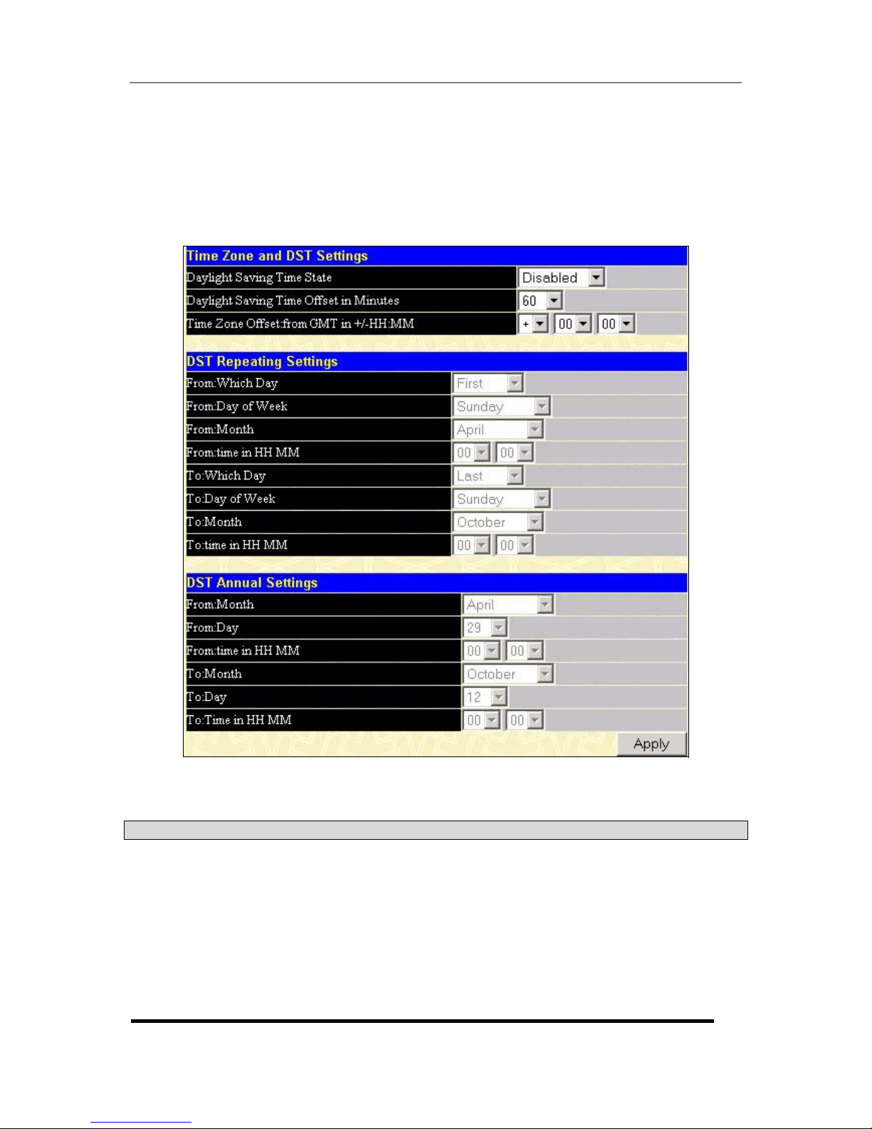
D-Link DGS-3324SR Layer 3 Stackable Gigabit Ethernet Switch
68
Click Apply to implement your changes.
Time Zone and DST
The following are screens used to configure time zones and Daylight Savings time settings for SNTP. Open the
Configuration folder, then the SNTP folder and click on the Time Zone and DST link, revealing the following
screen.
Figure 4- 37. Time Zone and DST Settings Page
The following parameters can set:
Parameter Description
Daylight Saving
Time State
Use this pull-down menu to Enable or Disable the DST Settings.
Daylight Saving
Time Offset in
Minutes
Use this pull-down menu to specify the amount of time that will
constitute your local DST offset − 30, 60, 90, or 120 minutes.
Time Zone Offset
from GMT in +/HH:MM
Use these pull-down menus to specify your local time zone’s offset
from Greenwich Mean Time (GMT.)
Page 84

D-Link DGS-3324SR Layer 3 Stackable Gigabit Ethernet Switch
69
DST Repeating
Settings
Using repeating mode will enable DST seasonal time adjustment.
Repeating mode requires that the DST beginning and ending date be
specified using a formula. For example, specify to begin DST on
Saturday during the second week of April and end DST on Sunday
during the last week of October.
From: Which Day
Should be From: Which Week. Enter the week of the month that DST
will start.
From: Day of Week
Enter the day of the week that DST will start on.
From: Month
Enter the month DST will start on.
From: time in HH:MM
Enter the time of day that DST will start on.
To: Which Day
Should be be To: Which Week. Enter the week of the month the DST
will end.
To: Day of Week
Enter the day of the week that DST will end.
To: Month
Enter the month that DST will end.
To: time in HH:MM
Enter the time DST will end.
DST Annual Settings
Using annual mode will enable DST seasonal time adjustment. Annual
mode requires that the DST beginning and ending date be specified
consisely. For example, specify to begin DST on April 3 and end DST
on October 14.
From: Month
Enter the month DST will start on, each year.
From: Day
Enter the day of the week DST will start on, each year.
From: Time in
HH:MM
Enter the time of day DST will start on, each year.
To: Month
Enter the month DST will end on, each year.
To: Day
Enter the day of the week DST will end on, each year.
To: Time in HH:MM
Enter the time of day that DST will end on, each year.
Click Apply to implement changes made to the Time Zone and DST window.
Configuring The Access Profile Table
Access profiles allow you to establish criteria to determine whether or not the Switch will forward packets based
on the information contained in each packet’s header. These criteria can be specified on a basis of VLAN, MAC
address or IP address.
Creating an access profile is divided into two basic parts. The first is to specify which part or parts of a frame the
Switch will examine, such as the MAC source address or the IP destination address. The second part is entering
the criteria the Switch will use to determine what to do with the frame. The entire process is described below in
two parts.
To display the currently configured Access Profiles on the Switch, open the Configuration folder and click on
the Access Profile Table link. This will open the Access Profile Table page, as shown below.
Page 85
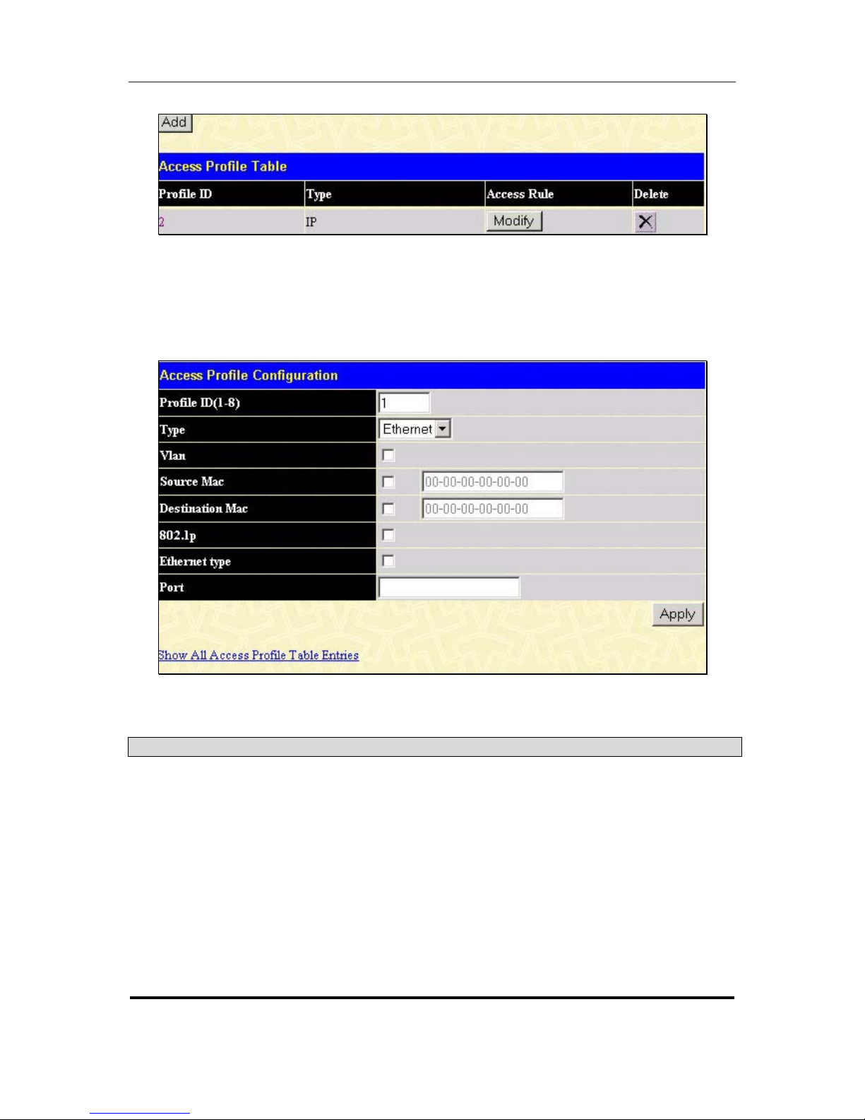
D-Link DGS-3324SR Layer 3 Stackable Gigabit Ethernet Switch
70
Figure 4- 38. Access Profile Table
To add an entry to the Access Profile Table, click the Add button. This will open the Access Profile
Configuration page, as shown below. There are two Access Profile Configuration pages − one for Ethernet
(or MAC address-based) profile configuration, and one for IP address-based profile configuration. You can
switch between the two Access Profile Configuration pages by using the Type drop-down menu, and clicking
on the Apply button. The page shown below is the Ethernet Access Profile Configuration page.
Figure 4- 39. Access Profile Table (Ethernet)
The following parameters can be set, for Ethernet:
Parameter Description
Profile ID (1-8)
Type in a unique identifier number for this profile set. This value can be set
from 1 – 8.
Type
Select profile based on Ethernet (MAC Address) or IP address. This will
change the menu according to the requirements for the type of profile.
Select Ethernet to instruct the Switch to examine the layer 2 part of each
packet header. Select IP to instruct the Switch to examine the IP address
in each frame’s header.
Vlan
Selecting this option instructs the Switch to examine the VLAN part of each
packet header and use this as the full or partial criterion for forwarding.
Source Mac
Source MAC Mask - Enter a MAC address mask for the source MAC
address.
Page 86
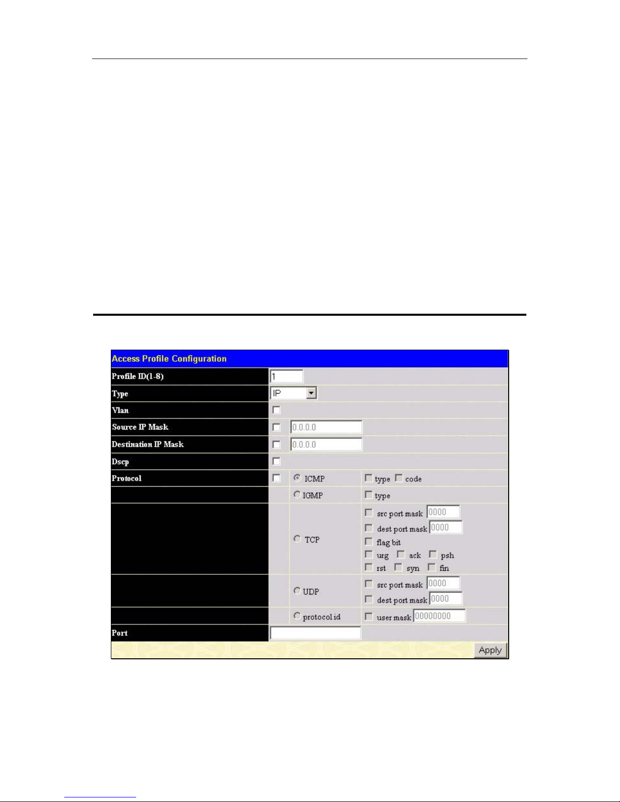
D-Link DGS-3324SR Layer 3 Stackable Gigabit Ethernet Switch
71
Destination Mac
Destination MAC Mask - Enter a MAC address mask for the destination
MAC address.
802.1p
Selecting this option instructs the Switch to examine the 802.1p priority
value of each packet header and use this as the, or part of the criterion for
forwarding.
Ethernet type
Selecting this option instructs the Switch to examine the Ethernet type
value in each frame’s header.
Port
The user may set the Access Profile Table on a per-port basis by
entering an entry in this field. The user may select all, denoting all ports
within the switch stack, or enter a port or ports. The port list is specified by
listing the lowest switch number and the beginning port number on that
switch, separated by a colon. Then the highest switch number, and the
highest port number of the range (also separated by a colon) are specified.
The beginning and end of the port list range are separated by a dash. For
example, 1:3 specifies switch number 1, port 3. 2:4 specifies switch
number 2, port 4. 1:3-2:4 specifies all of the ports between switch 1, port 3
and switch 2, port 4 − in numerical order.
The page shown below is the IP Access Profile Configuration page.
Figure 4- 40. Access Profile Configuration (IP)
The following parameters can be set, for IP:
Page 87

D-Link DGS-3324SR Layer 3 Stackable Gigabit Ethernet Switch
72
Parameter Description
Profile ID(1-8)
Type in a unique identifier number for this profile set. This value can be set
from 1 – 8.
Type
Select profile based on Ethernet (MAC Address) or IP address. This will
change the menu according to the requirements for the type of profile.
Select Ethernet to instruct the Switch to examine the layer 2 part of each
packet header. Select IP to instruct the Switch to examine the IP address
in each frame’s header.
Vlan
Selecting this option instructs the Switch to examine the VLAN part of each
packet header and use this as the, or part of the criterion for forwarding.
Source IP Mask
Source IP Mask - Enter an IP address mask for the source IP address.
Destination IP Mask
Destination IP Mask - Enter an IP address mask for the destination IP
address.
Dscp
Selecting this option instructs the Switch to examine the DiffServ Code part
of each packet header and use this as the, or part of the criterion for
forwarding.
Protocol
Selecting this option instructs the Switch to examine the protocol type
value in each frame’s header. You must then specify what protocol(s) to
include according to the following guidelines:
Select ICMP to instruct the Switch to examine the Internet Control
Message Protocol (ICMP) field in each frame’s header.
Select Type to further specify that the access profile will apply an ICMP
type value, or specify Code to further specify that the access profile will
apply an ICMP cod value.
Select IGMP to instruct the Switch to examine the Internet Group
Management Protocol (IGMP) field in each frame’s header.
Select Type to further specify that the access profile will apply an IGMP
type value
Select TCP to use the TCP port number contained in an incoming packet
as the forwarding criterion. Selecting TCP requires that you specify a
source port mask and/or a destination port mask. The user may also
identify which flag bits to deny. Flag bits are parts of a packet that
determine what to do with the packet. The user may deny packets by
denying certain flag bits within the packets, by checking the boxes
corresponding to the flag bits of the TCP field. The user may choose
between urg (urgent), ack (acknowledgement), psh (push), rst (reset),
syn (synchronize), fin (finish).
src port mask − Specify a TCP port mask for the source port in hex form
(hex 0x0-0xffff), which you wish to deny.
dest port mask − Specify a TCP port mask for the destination port in hex
form (hex 0x0-0xffff) which you wish to deny.
Select UDP to use the UDP port number contained in an incoming packet
as the forwarding criterion. Selecting UDP requires that you specify a
source port mask and/or a destination port mask.
src port mask − Specify a TCP port mask for the source port in hex form
(hex 0x0-0xffff).
Page 88
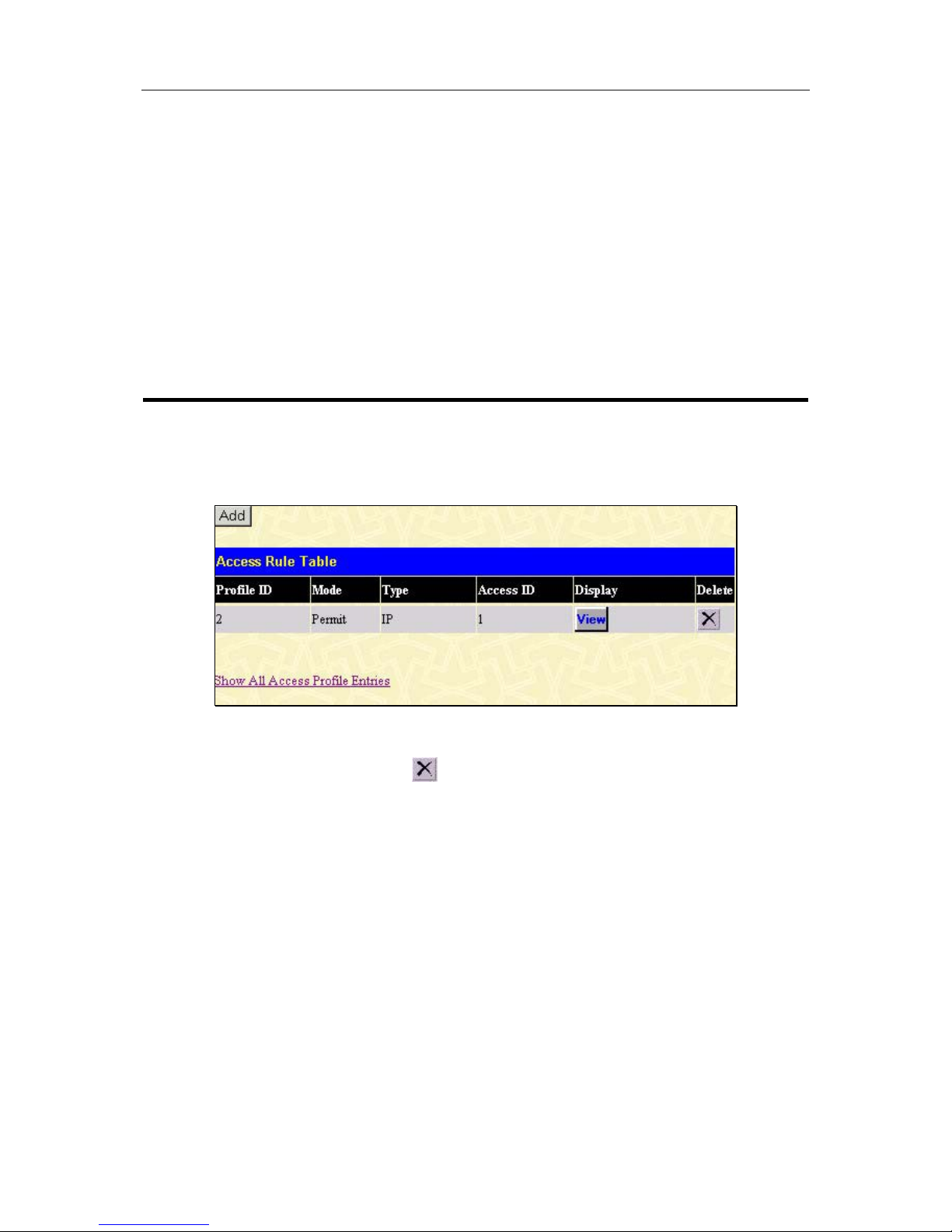
D-Link DGS-3324SR Layer 3 Stackable Gigabit Ethernet Switch
73
dest port mask − Specify a TCP port mask for the destination port in hex
form (hex 0x0-0xffff).
protocol id − Specify a Layer 4 port mask for the destination port in hex
form (hex 0x0-0xffffffff).
Port
The user may set the Access Profile Table on a per-port basis by
entering an entry in this field. The user may select all, denoting all ports
within the switch stack, or enter a port or ports. The port list is specified by
listing the lowest switch number and the beginning port number on that
switch, separated by a colon. Then the highest switch number, and the
highest port number of the range (also separated by a colon) are specified.
The beginning and end of the port list range are separated by a dash. For
example, 1:3 specifies switch number 1, port 3. 2:4 specifies switch
number 2, port 4. 1:3-2:4 specifies all of the ports between switch 1, port 3
and switch 2, port 4 − in numerical order.
To establish the rule for a previously created Access Profile:
In the Configuration folder, click the Access Profile Table link opening the Access Profile Table. Under the
heading Access Rule, clicking Modify, will open the following window.
Figure 4- 41. Access Rule Table window
To create a new rule set for the access profile click the Add button. A new window is displayed. To remove a
previously created rule, select it and click the
button.
Page 89
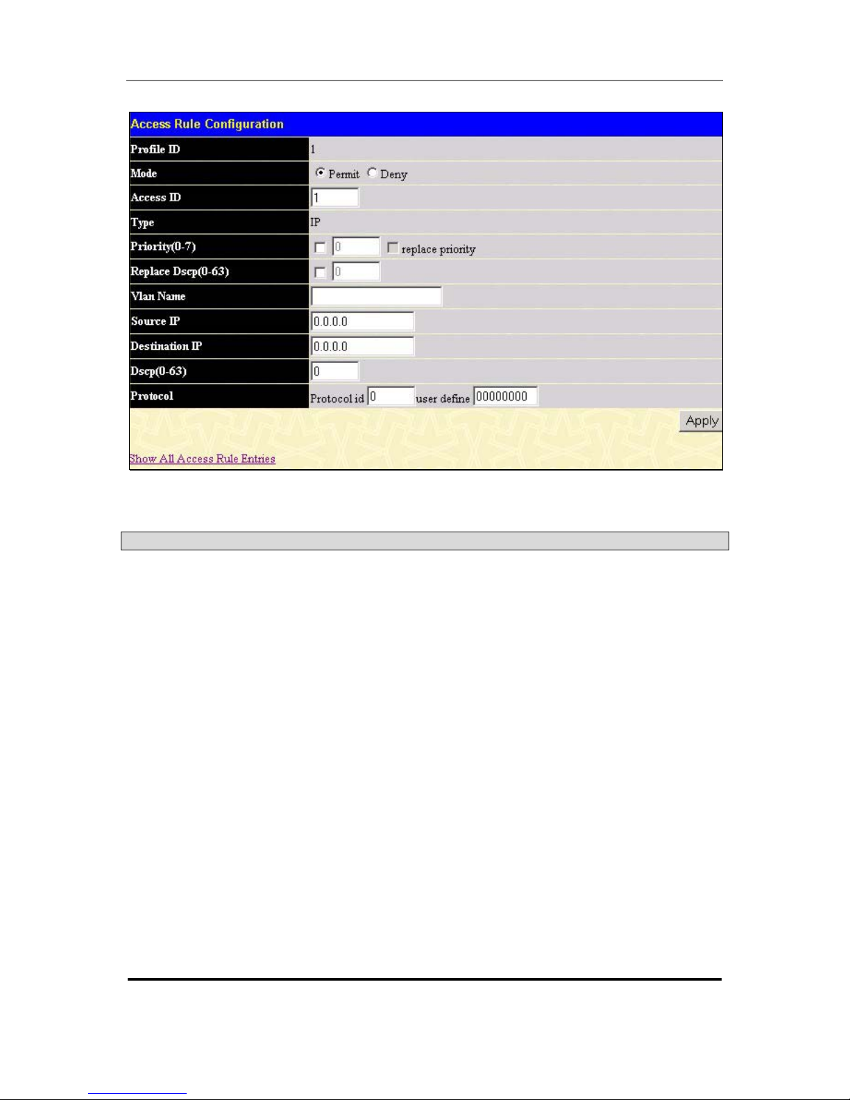
D-Link DGS-3324SR Layer 3 Stackable Gigabit Ethernet Switch
74
Figure 4- 42. Access Rule Configuration window (IP)
Configure the following Access Rule Configuration settings:
Parameter Description
Profile ID
This is the identifier number for this profile set.
Mode
Select Permit to specify that the packets that match the access profile are
forwarded by the Switch, according to any additional rule added (see
below).
Select Deny to specify that packets that do not match the access profile
are not forwarded by the Switch and will be filtered.
Access ID
Type in a unique identifier number for this access. This value can be set
from 1 – 50.
Type
Selected profile based on Ethernet (MAC Address) or IP address. Ethernet
instructs the Switch to examine the layer 2 part of each packet header. IP
instructs the Switch to examine the IP address in each frame’s header.
Priority (0-7)
Select this option to instruct the Switch to use the 802.1p priority value
entered in the adjacent field for packets that meet the criteria. A number
between 0 − lowest priority, and 7 − highest priority, can be entered.
Replace Dscp (0-63)
Select this option to instruct the Switch to replace the DSCP value (in a
packet that meets the selected criteria) with the value entered in the
adjacent field.
Vlan Name
Allows the entry of a name for a previously configured VLAN.
Source IP
Source IP Address - Enter an IP Address mask for the source IP address.
Page 90
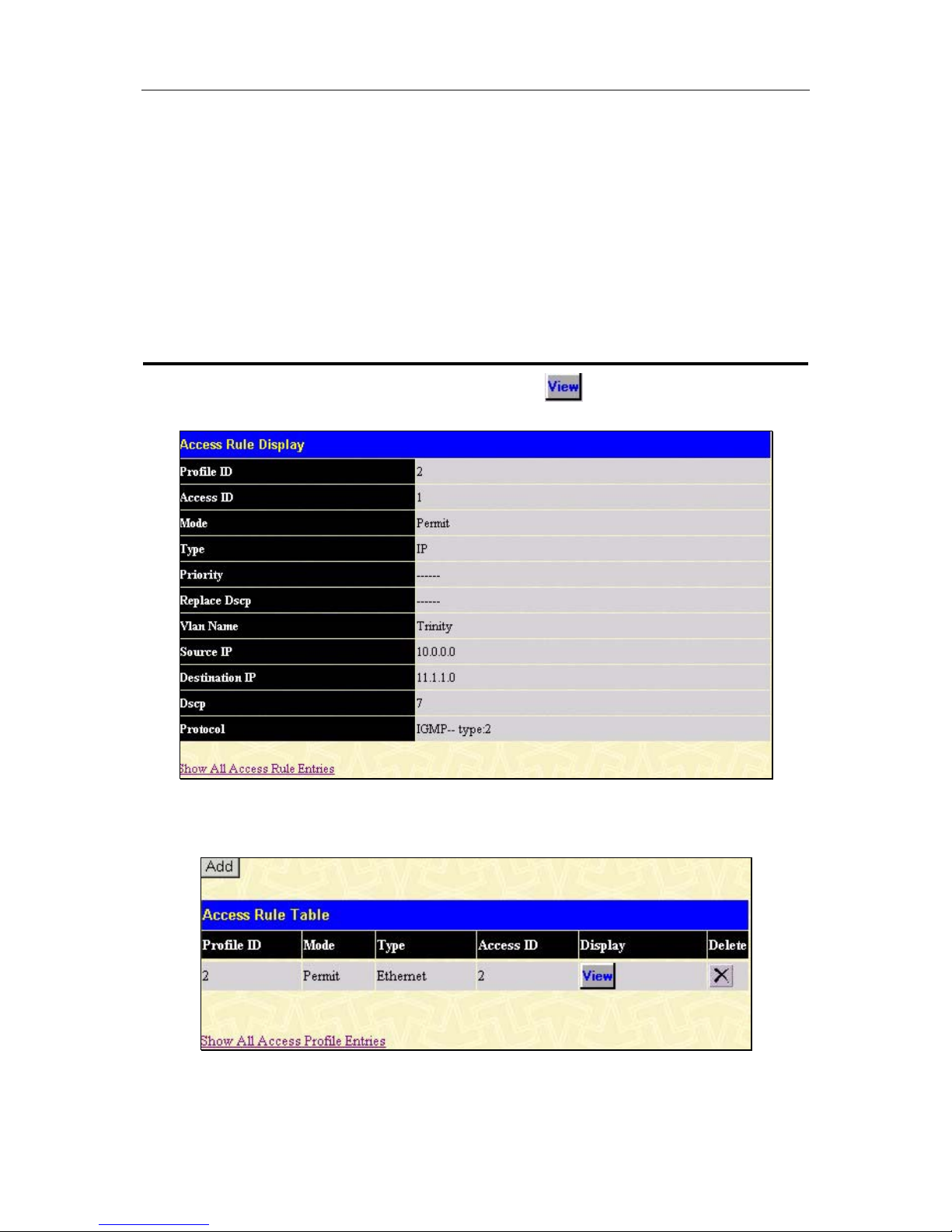
D-Link DGS-3324SR Layer 3 Stackable Gigabit Ethernet Switch
75
Destination IP
Destination IP Address- Enter an IP Address mask for the destination IP
address.
Dscp(0-63)
This field allows the user to enter a Dscp value in the space provided,
which will instruct the Switch to examine the DiffServ Code part of each
packet header and use this as the, or part of the criterion for forwarding.
The user may choose a value between 0 and 63.
Protocol
This field allows the user to modify the protocol used to configure the
Access Rule Table, depending on which protocol the user has chosen in
the Access Profile Table. In the example above IGMP is the protocol
chosen and therefore the user may modify the IGMP settings for this
access profile.
To view the settings of a previously correctly configured rule, click in the Access Rule Table to view the
following screen:
Figure 4- 43. Access Rule Display window (IP)
To configure the Access Rule for Ethernet, open the Access Profile Table (figure 4-36) and click Modify for an
Ethernet entry. This will open the following screen:
Figure 4- 44. Access Rule Table
Page 91
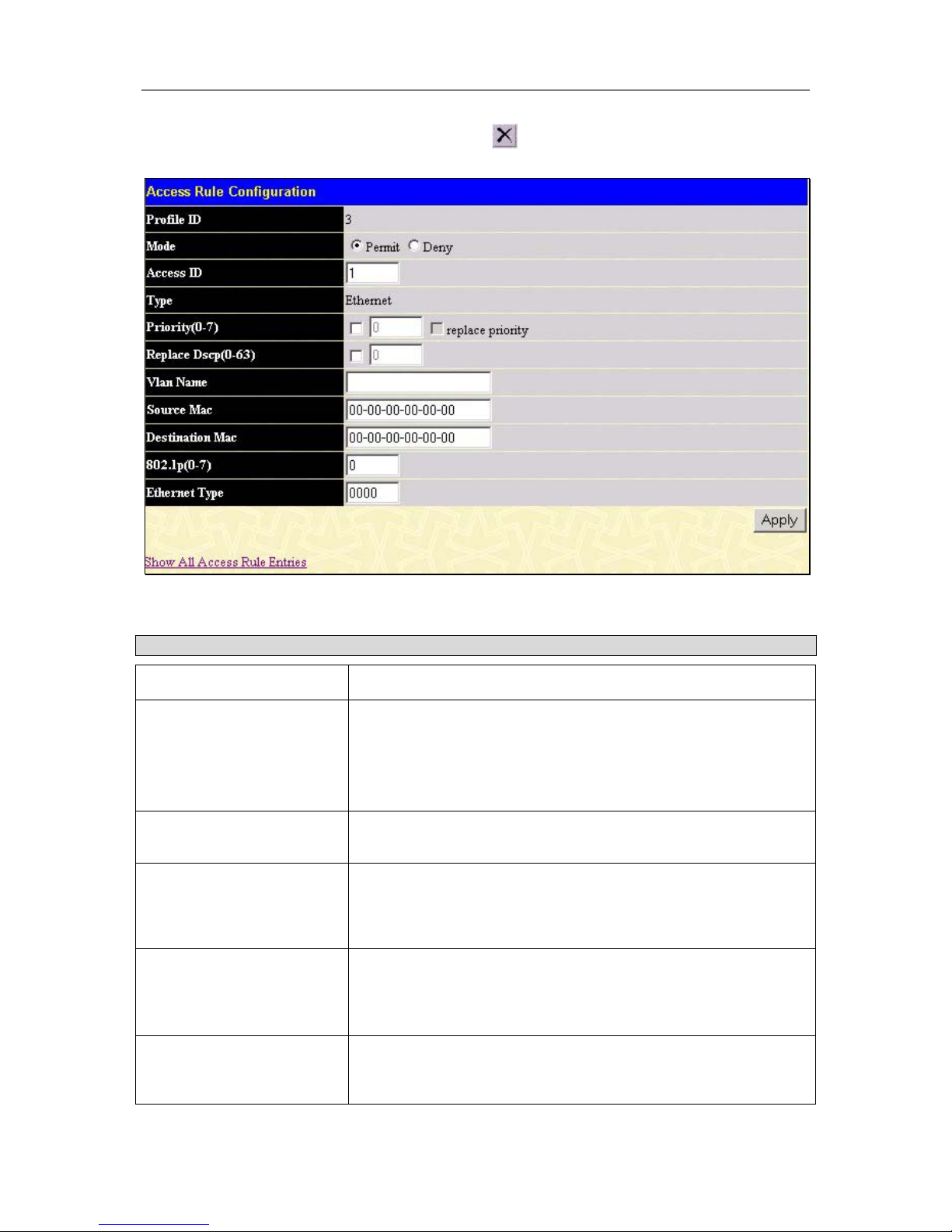
D-Link DGS-3324SR Layer 3 Stackable Gigabit Ethernet Switch
76
To remove a previously created rule, select it and click the
button. To add a new Access Rule, click the Add
button:
Figure 4- 45. Access Rule Configuration window (Ethernet).
To set the Access Rule for Ethernet, adjust the following parameters and click Apply.
Parameters Description
Profile ID
This is the identifier number for this profile set.
Mode
Select Permit to specify that the packets that match the access
profile are forwarded by the Switch, according to any additional rule
added (see below).
Select Deny to specify that packets that do not match the access
profile are not forwarded by the Switch and will be filtered.
Access ID
Type in a unique identifier number for this access. This value can be
set from 1 – 50.
Type
Selected profile based on Ethernet (MAC Address) or IP address.
Ethernet instructs the Switch to examine the layer 2 part of each
packet header. IP instructs the Switch to examine the IP address in
each frame’s header.
Priority(0-7)
Select this option to instruct the Switch to use the 802.1p priority
value entered in the adjacent field for packets that meet the criteria. A
number between 0 − lowest priority, and 7 − highest priority, can be
entered.
Replace Dscp(0-63)
Select this option to instruct the Switch to replace the DSCP value (in
a packet that meets the selected criteria) with the value entered in the
adjacent field.
Page 92
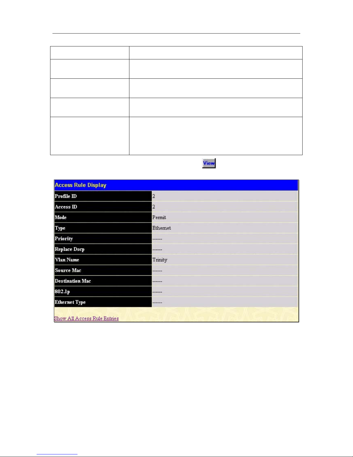
D-Link DGS-3324SR Layer 3 Stackable Gigabit Ethernet Switch
77
Vlan Name
Allows the entry of a name for a previously configured VLAN.
Source Mac
Source MAC Address - Enter a MAC Address for the source MAC
address.
Destination Mac
Destination MAC Address- Enter a MAC Address mask for the
destination MAC address.
802.1p(0-7)
Enter a value from 0-7 to specify that the access profile will apply only
to packets with this 802.1p priority value.
Ethernet Type
Specifies that the access profile will apply only to packets with this
hexadecimal 802.1Q Ethernet type value (hex 0x0-0xffff) in the
packet header. The Ethernet type value may be set in the form: hex
0x0-0xffff, which means the user may choose any combination of
letters and numbers ranging from a-f and from 0-9999.
To view the settings of a previously correctly configured rule, click in the Access Rule Table to view the
following screen:
Figure 4- 46. Access Rule Display window (Ethernet)
Configuring The Port Access Entity
802.1X Port-based Network Access Control
The Switch is an implementation of the server side of IEEE 802.1X-Port Based Network Access Control.
Through this mechanism, users have to be authorized before being able to access the network. See the following
figure:
Page 93
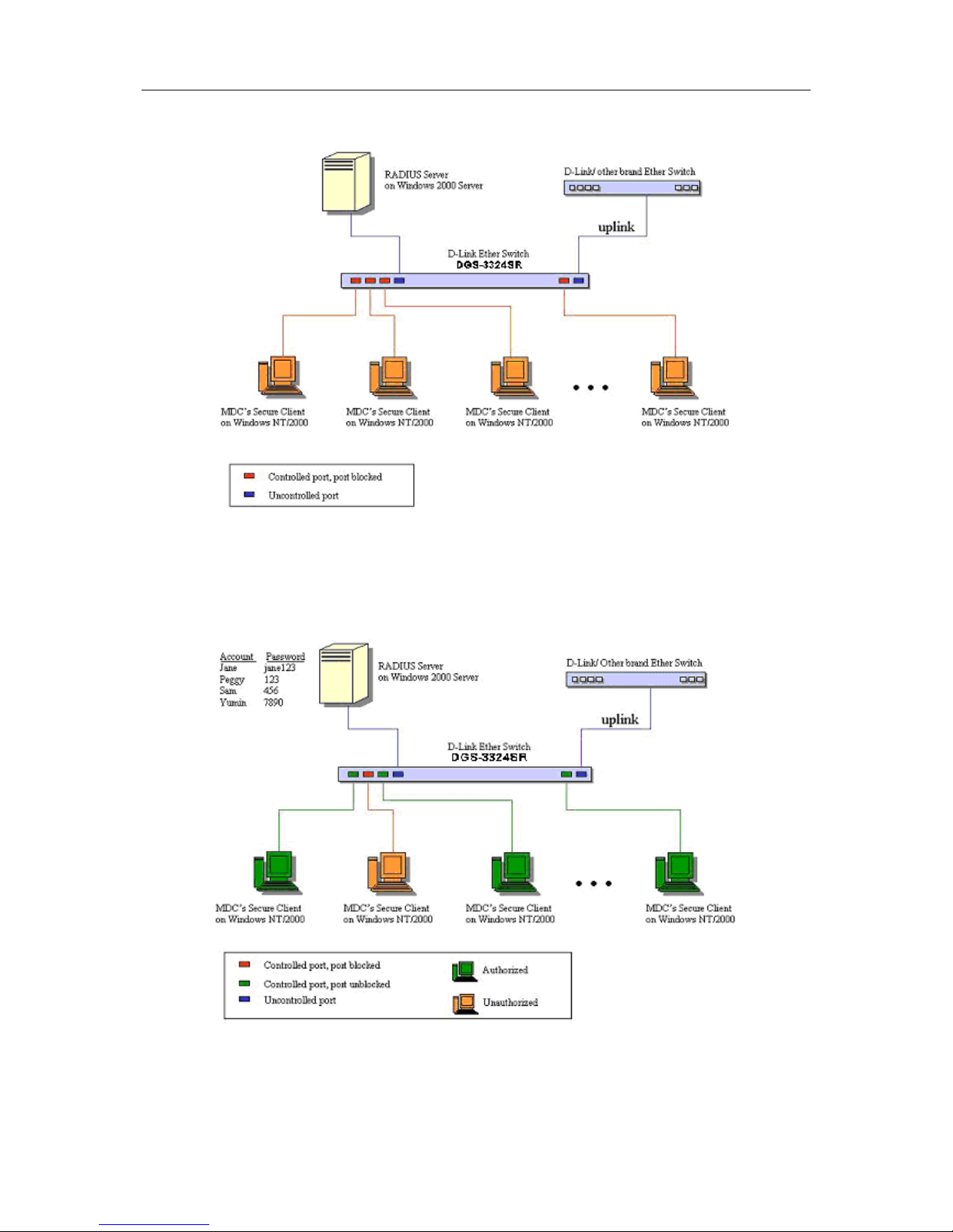
D-Link DGS-3324SR Layer 3 Stackable Gigabit Ethernet Switch
78
Figure 4- 47. Typical 802.1X Configuration Prior to User Authentication
Once the user is authenticated, the Switch unblocks the port that is connected to the user as shown in the next
figure.
Figure 4- 48. Typical 802.1X Configuration with User Authentication
The user’s information, including account number, password, and configuration details such as IP address and
billing information, is stored in a centralized RADIUS server.
Page 94
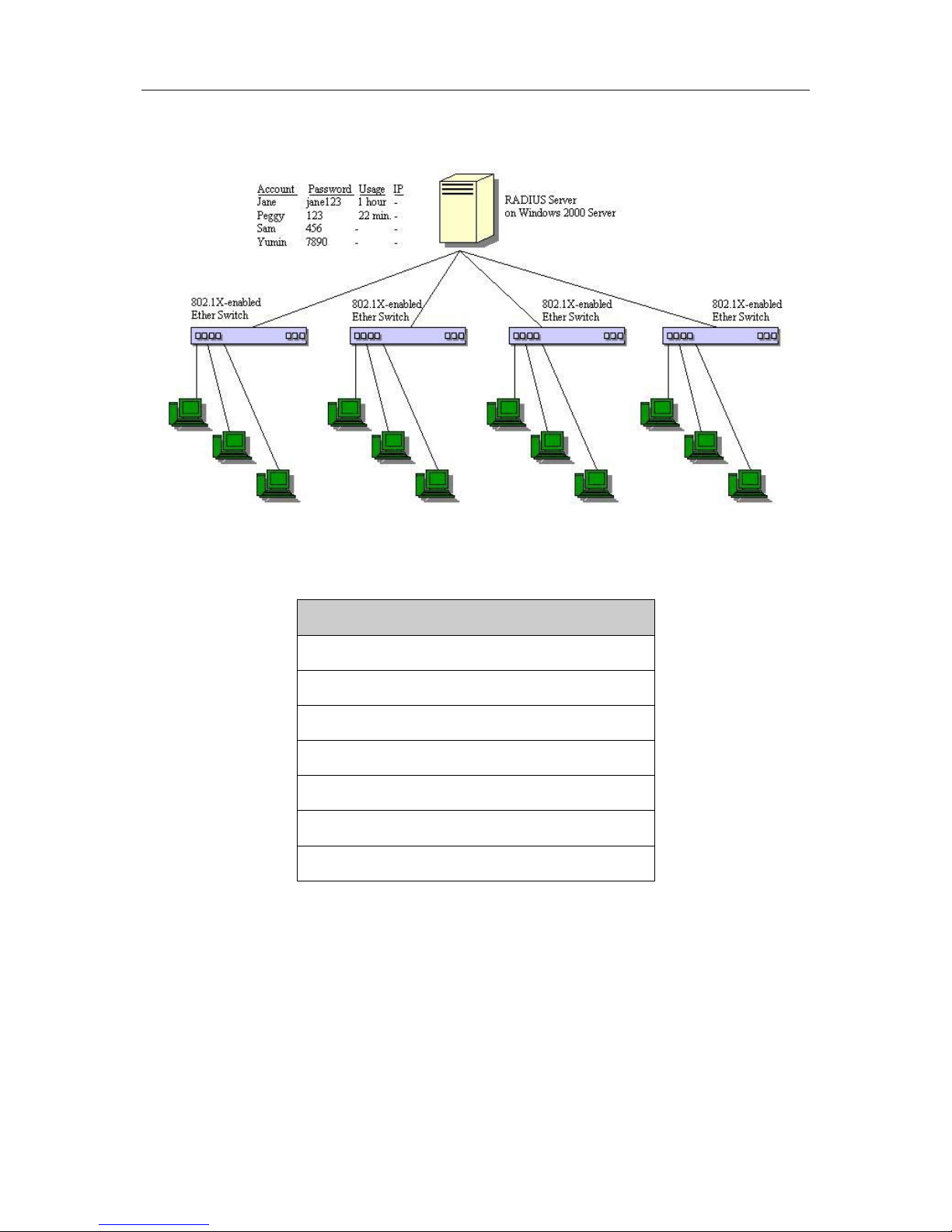
D-Link DGS-3324SR Layer 3 Stackable Gigabit Ethernet Switch
79
Figure 4- 49. Typical Configuration with 802.1X Fully Implemented
State Machine Name
Port Timers state machine
Authenticator PAE state machine
The Authenticator Key Transmit state machine
Reauthentication Timer state machine
Backend Authentication state machine
Controlled Directions state machine
The Key Receive state machine
Table 4- 3. Conformance to IEEE 802.1X Standards
Configure Authenticator
To display the current 802.1X Authenticator Settings on the Switch, open the Configuration folder, and then
the Port Access Entity folder and finally click on the Configure Authenticator link. This will open the 802.1X
Authenticator Settings page, as shown below.
Page 95
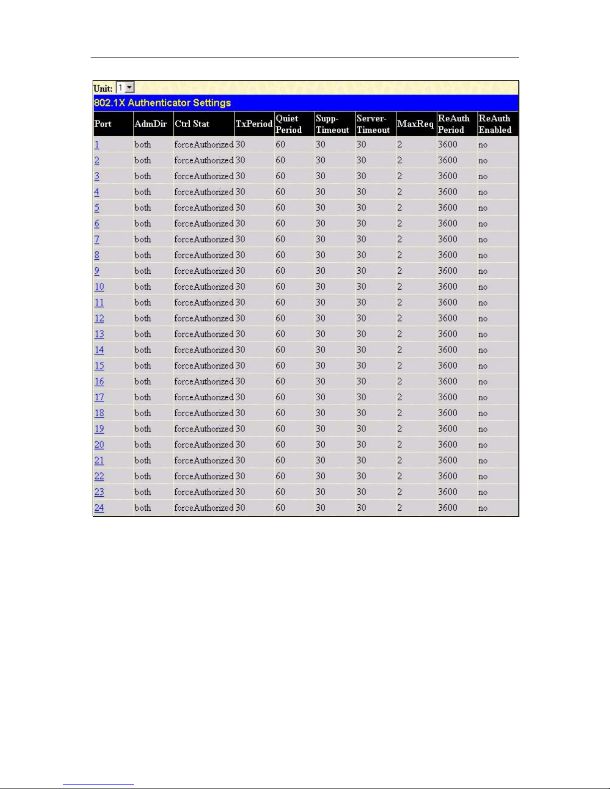
D-Link DGS-3324SR Layer 3 Stackable Gigabit Ethernet Switch
80
Figure 4- 50. 802.1x Authenticator Settings window
To configure the 802.1X Authenticator Settings for a given port, click on the blue port link under the Port
heading. This will open the 802.1X Authenticator Settings page, as shown below.
Page 96
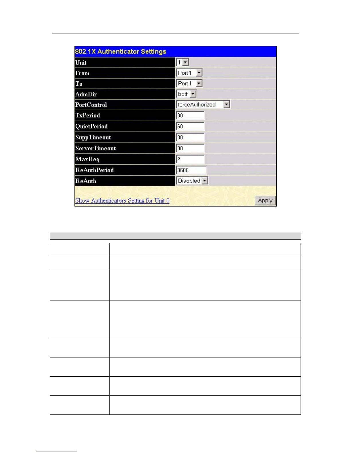
D-Link DGS-3324SR Layer 3 Stackable Gigabit Ethernet Switch
81
Figure 4- 51. 802.1x Authenticator Settings modify window
This window allows you to set the following features:
Parameter Description
Unit
Allows you to select a switch from a switch stack using that switch’s Unit ID.
From [ ] To [ ]
Enter the port or ports to be set.
AdmDir
From the pull-down menu, select whether a controlled Port that is
unauthorized will exert control over communication in both (both) receiving
and transmitting directions, or just the receiving direction (in). The default is
both.
Port Control
Displays the administrative control over the port’s authorization status.
forceAuthorized forces the Authenticator of the port to become Authorized.
forceUnauthorized forces the port to become Unauthorized. Auto means the
port state reflects the outcome of the authentication exchange between
supplicant, authenticator, and authentication. The default is forceAuthorized.
TxPeriod
Select the time to wait for a response from a supplicant (user) to send EAP
Request/Identity packets. The default is 30 seconds.
Quiet Period
Select the time interval between authentication failure and the start of a new
authentication attempt. The default is 60 seconds.
SuppTimeout
Select the time to wait for a response from a supplicant (user) for all EAP
packets, except for the Request/Identity packets. The default is 30 seconds
Server Timeout
Select the length of time to wait for a response from a RADIUS server. The
default is 30 seconds.
Page 97
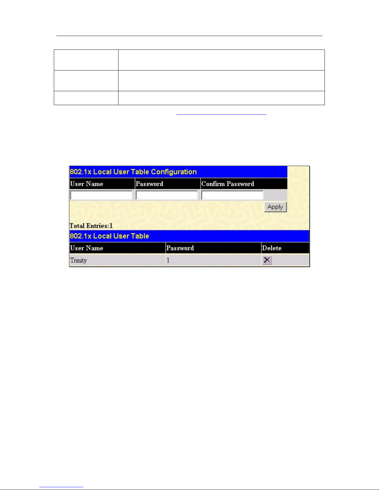
D-Link DGS-3324SR Layer 3 Stackable Gigabit Ethernet Switch
82
Max Req
Select the maximum number of times to retry sending packets to the
supplicant. The default is 2.
ReAuthPeriod
Select the time interval between successive re-authentications. The default is
3600 seconds.
ReAuth
Enable or disable reauthentication. The default is Disabled.
Click Apply to implement your changes. Click the Show Authenticators Settings for Unit to return to the 802.1X
Authenticator Settings window.
Configuring Local Users
In the configuration folder, open the Port Access Entity folder and click Local users to open the 802.1x Local
User Table Configuration window. This window will allow the user to set different local users on the Switch.
Figure 4- 52. 802.1x Local User Table Configuration window
Enter a User Name, Password and confirmation of that password. Properly configured local users will be
displayed in the 802.1x Local User Table in the same window.
PAE System Control
Port Capability Settings
Existing 802.1x port settings are displayed and can be configured using the window below.
Click Port Capability Settings on the PAE Access Entity folder on the Configuration menu to open the
802.1X Capability Settings window:
Page 98
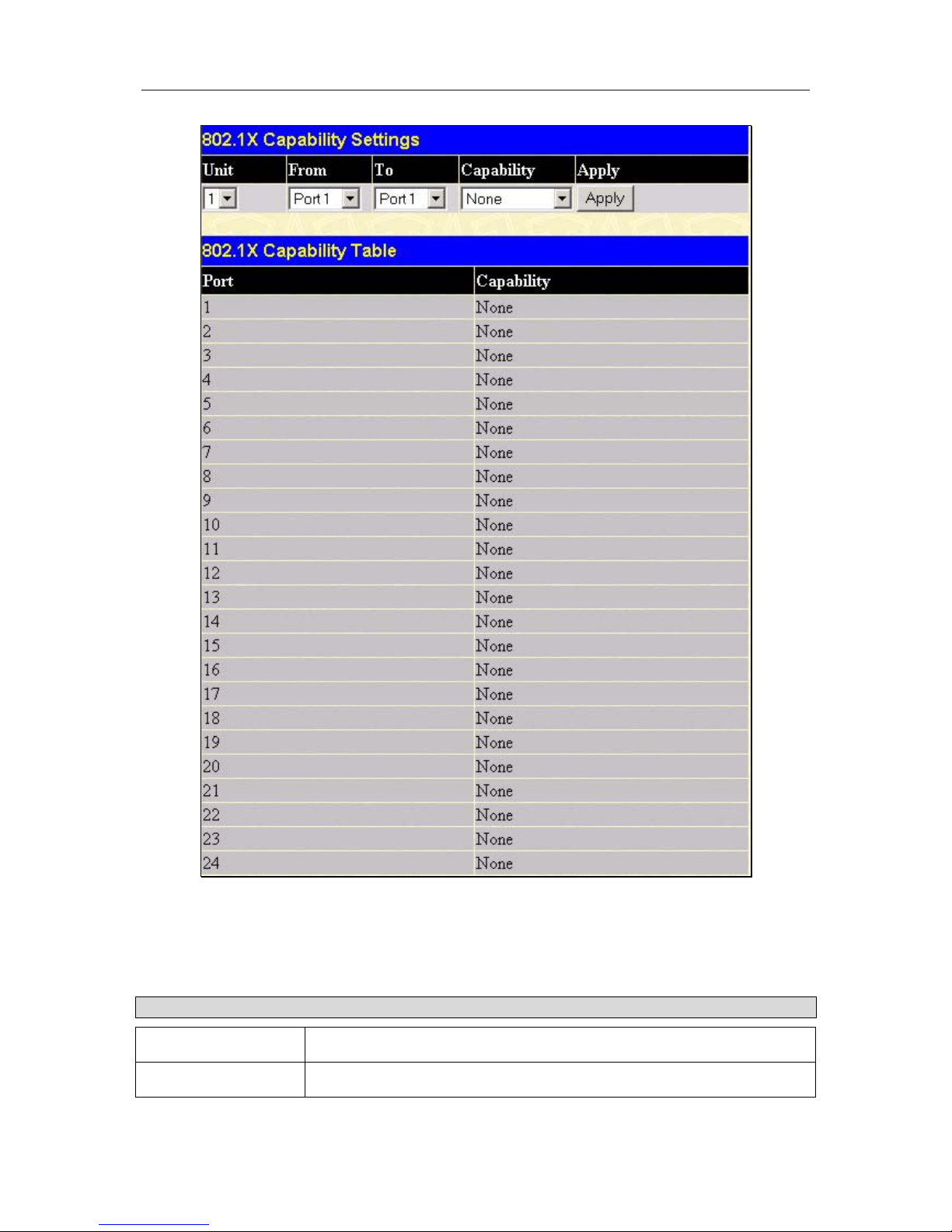
D-Link DGS-3324SR Layer 3 Stackable Gigabit Ethernet Switch
83
Figure 4- 53. 802.1x Capability Settings and Table window
To set up the Switch’s 802.1x port-based authentication, select which ports are to be configured in the From and
To fields. Next, enable the ports by selecting Authenticator from the drop-down menu under Capability. Click
Apply to let your change take effect.
Configure the following 802.1x capability settings:
Parameter Description
Unit
Allows you to select a switch from a switch stack using that switch’s Unit ID.
From and To Ports being configured for 802.1x settings.
Page 99
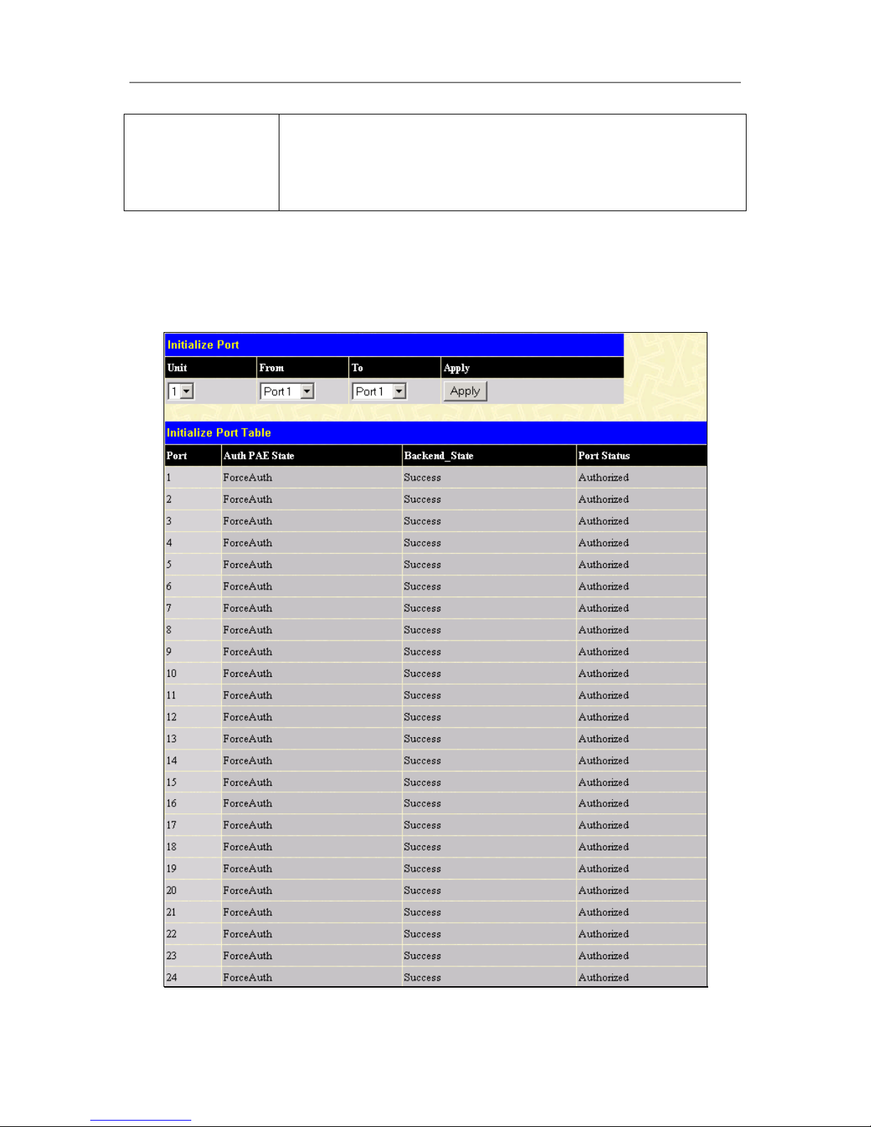
D-Link DGS-3324SR Layer 3 Stackable Gigabit Ethernet Switch
84
Capability
Two role choices can be selected:
Authenticator − A user must pass the authentication process to gain access
to the network.
None − The port is not controlled by the 802.1x functions.
Initializing Ports
Existing 802.1x port settings are displayed and can be configured using the window below.
Click Initialize Port(s) on the PAE Access Entity folder on the Configuration menu to open the 802.1x Port
Initial window:
Figure 4- 54. 802.1x Port Initial and Port Authentication state window
Page 100
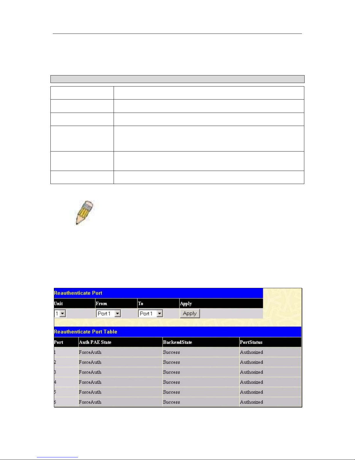
D-Link DGS-3324SR Layer 3 Stackable Gigabit Ethernet Switch
85
This window allows you to initialize a port or group of ports. The Initialize Port Table in the bottom half of the
window displays the current status of the port(s) once you have clicked Apply.
This window displays the following information:
Parameter Description
Unit
Allows you to select a switch from a switch stack using that switch’s Unit ID.
From and To
Ports selected to be initialized.
Port
A read only field indicating a port on the switch.
Auth PAE State
The Authenticator PAE State will display one of the following: Initialize,
Disconnected, Connecting, Authenticating, Authenticated, Aborting, Held,
ForceAuth, ForceUnauth, and N/A.
Backend State
The Backend Authentication State will display one of the following: Request,
Response, Success, Fail, Timeout, Idle, Initialize, and N/A.
Port Status
The status of the controlled port can be authorized, unauthorized, or N/A.
Note: The user must first globally enable 802.1X in the Advanced
Settings window in the Configuration folder before initializing ports.
Information in the Initialize Ports Table cannot be viewed before enabling
802.1X.
Reauthenticate Port(s)
This window allows you to reauthenticate a port or group of ports by selecting the stacking Unit, choosing a port
or group of ports by using the pull down menus From and To and clicking Apply. The Reauthenticate Port
Table displays the current status of the reauthenticated port(s) once you have clicked Apply.
Click Reauthenticate Port(s) on the PAE Access Entity folder on the Configuration menu to open the
Reauthenticate Port(s) window:
Figure 4- 55. Reauthenticate Port and Reauthenticate Port Table window
 Loading...