

Page 1

Manual
Product Model:
xStack
®
DGS-3200 Series
Layer 2 Managed Gigabit Ethernet Switch
Release 1.5
Page 2

_____________________________________________
Information in this document is subject to change without notice.
© 2009 D-Link Corporation. All rights reserved.
Reproduction in any manner whatsoever without the written permission of D-Link Corporation is strictly forbidden.
Trademarks used in this text: D-Link and the D-LINK logo are trademarks of D-Link Corporation; Microsoft and Windows are registered trademarks of Microsoft
Corporation.
Other trademarks and trade names may be used in this document to refer to either the entities claiming the marks and names or their products. D-Link Corporation
disclaims any proprietary interest in trademarks and trade names other than its own.
June 2009 P/N 651GS32XX035G
Page 3

xStack® DGS-3200 Series Layer 2 Gigabit Ethernet Managed Switch
iii
Table of Contents
Intended Readers........................................................................................................................................................................... ix
Typographical Conventions ...........................................................................................................................................................................ix
Notes, Notices, and Cautions ......................................................................................................................................................... x
Safety Cautions ...............................................................................................................................................................................................x
General Precautions for Rack-Mountable Products .......................................................................................................................................xi
Lithium Battery Precaution.................................................................................................................................................................... xiii
Protecting Against Electrostatic Discharge................................................................................................................................................. xiii
Web-based Switch Configuration...................................................................................................................1
Introduction.................................................................................................................................................................................... 1
Logging onto the Web Manager......................................................................................................................................................................1
Web-based User Interface...............................................................................................................................................................................2
Areas of the User Interface ........................................................................................................................................................................2
Web Pages.......................................................................................................................................................................................................3
Configuration ...................................................................................................................................................5
Device Information ........................................................................................................................................................................ 6
System Information........................................................................................................................................................................ 7
Serial Port Settings......................................................................................................................................................................... 8
IP Address ...................................................................................................................................................................................... 8
Setting the Switch’s IP Address using the Console Interface ..................................................................................................................10
IPv6 Interface Settings ................................................................................................................................................................. 10
IPv6 Route Table ......................................................................................................................................................................... 12
IPv6 Neighbor Settings ................................................................................................................................................................ 13
Port Configuration........................................................................................................................................................................ 14
Port Settings..................................................................................................................................................................................................14
Port Description ............................................................................................................................................................................................15
Port Error Disabled .......................................................................................................................................................................................16
Static ARP Settings...................................................................................................................................................................... 16
User Accounts.............................................................................................................................................................................. 18
Admin and User Privileges......................................................................................................................................................................18
System Log Configuration........................................................................................................................................................... 19
System Log Settings......................................................................................................................................................................................19
System Log Host...........................................................................................................................................................................................20
System Severity Settings.............................................................................................................................................................. 20
DHCP/BOOTP Relay................................................................................................................................................................... 21
DHCP/BOOTP Relay Global Settings .......................................................................................................................................................... 21
DHCP/BOOTP Relay Interface Settings.......................................................................................................................................................24
DHCP Local Relay Settings......................................................................................................................................................... 24
DHCP Auto Configuration Settings ............................................................................................................................................. 25
MAC Address Aging Time .......................................................................................................................................................... 26
Web Settings ................................................................................................................................................................................ 26
Page 4

xStack® DGS-3200 Series Layer 2 Gigabit Ethernet Managed Switch
iv
Telnet Settings.............................................................................................................................................................................. 27
Password Encryption.................................................................................................................................................................... 27
CLI Paging Settings ..................................................................................................................................................................... 28
Firmware Information .................................................................................................................................................................. 28
Power Saving Settings.................................................................................................................................................................. 30
Dual Configuration Settings......................................................................................................................................................... 31
SMTP Settings ............................................................................................................................................................................. 33
Ping Test ...................................................................................................................................................................................... 34
SNTP Settings .............................................................................................................................................................................. 35
Time Settings ................................................................................................................................................................................................35
Time Zone Settings.......................................................................................................................................................................................36
MAC Notification Settings .......................................................................................................................................................... 37
MAC Notification Global Settings................................................................................................................................................................37
MAC Notification Port Settings.................................................................................................................................................................... 38
SNMP Settings............................................................................................................................................................................. 39
SNMP Global State Settings .........................................................................................................................................................................40
SNMP Linkchange Trap Settings..................................................................................................................................................................40
SNMP View Table........................................................................................................................................................................................41
SNMP Group Table ......................................................................................................................................................................................42
SNMP User Table .........................................................................................................................................................................................43
SNMP Community Table.............................................................................................................................................................................. 44
SNMP Host Table ......................................................................................................................................................................................... 45
SNMP v6Host Table .....................................................................................................................................................................................46
SNMP Engine ID .......................................................................................................................................................................................... 47
SNMP Trap Configuration............................................................................................................................................................................47
RMON ..........................................................................................................................................................................................................48
CPU Filter L3 Control Packet Settings ........................................................................................................................................ 48
Single IP Management................................................................................................................................................................. 48
Single IP Settings..........................................................................................................................................................................................50
Topology.......................................................................................................................................................................................................52
Firmware Upgrade ........................................................................................................................................................................................58
Configuration File Backup/Restore...............................................................................................................................................................58
Upload Log File ............................................................................................................................................................................................58
SD Card FS Settings..................................................................................................................................................................... 59
L2 Features..................................................................................................................................................... 61
Jumbo Frame................................................................................................................................................................................ 61
Egress Filter Settings.................................................................................................................................................................... 62
802.1Q VLAN.............................................................................................................................................................................. 62
Private VLAN Settings ................................................................................................................................................................ 71
802.1v Protocol VLAN................................................................................................................................................................ 76
802.1v Protocol Group Settings .................................................................................................................................................................... 76
802.1v Protocol VLAN Settings ...................................................................................................................................................................77
MAC-based VLAN Settings ........................................................................................................................................................ 78
GVRP Settings ............................................................................................................................................................................. 78
Page 5

xStack® DGS-3200 Series Layer 2 Gigabit Ethernet Managed Switch
v
PVID Auto Assign Settings ......................................................................................................................................................... 79
Port Trunking............................................................................................................................................................................... 80
VLAN Trunk Settings .................................................................................................................................................................. 83
LACP Port Settings...................................................................................................................................................................... 84
Traffic Segmentation.................................................................................................................................................................... 85
IGMP Snooping ........................................................................................................................................................................... 85
IGMP Snooping Settings ..............................................................................................................................................................................85
Data Driven Learning Settings...................................................................................................................................................................... 89
ISM VLAN Settings......................................................................................................................................................................................90
Restrictions and Provisos......................................................................................................................................................................... 90
ISM Profile Settings......................................................................................................................................................................................93
IP Multicast Profile Settings .........................................................................................................................................................................94
Limited Multicast Address Range Settings...................................................................................................................................................95
Max Multicast Group Settings ......................................................................................................................................................................96
MLD Snooping Settings............................................................................................................................................................... 96
Port Mirroring ............................................................................................................................................................................ 100
Loopback Detection Settings ..................................................................................................................................................... 101
Spanning Tree ............................................................................................................................................................................ 102
STP Bridge Global Settings ........................................................................................................................................................................105
STP Port Settings ........................................................................................................................................................................................ 107
MST Configuration Identification...............................................................................................................................................................108
STP Instance Settings..................................................................................................................................................................................109
MSTP Port Information ..............................................................................................................................................................................110
Forwarding & Filtering .............................................................................................................................................................. 111
Unicast Forwarding.....................................................................................................................................................................................111
Multicast Forwarding..................................................................................................................................................................................111
Multicast Filtering Mode.............................................................................................................................................................................112
QoS ................................................................................................................................................................113
Bandwidth Control..................................................................................................................................................................... 115
Traffic Control ........................................................................................................................................................................... 116
802.1p Default Priority............................................................................................................................................................... 118
802.1p User Priority ................................................................................................................................................................... 118
QoS Scheduling Mechanism...................................................................................................................................................... 119
Security ......................................................................................................................................................... 120
Safeguard Engine....................................................................................................................................................................... 120
Trusted Host............................................................................................................................................................................... 122
IP-MAC-Port Binding (IMPB)................................................................................................................................................... 123
IMPB Global Settings ................................................................................................................................................................................. 125
IMPB Port Settings .....................................................................................................................................................................................126
IMPB Entry Settings ...................................................................................................................................................................................128
DHCP Snooping Entries .............................................................................................................................................................................129
MAC Block List..........................................................................................................................................................................................130
Port Security............................................................................................................................................................................... 131
Port Security Settings..................................................................................................................................................................................131
Page 6

xStack® DGS-3200 Series Layer 2 Gigabit Ethernet Managed Switch
vi
Port Lock Entries ........................................................................................................................................................................................132
DHCP Server Screening............................................................................................................................................................. 133
DHCP Screening Port Settings....................................................................................................................................................................133
DHCP Offer Filtering..................................................................................................................................................................................134
Guest VLAN .............................................................................................................................................................................. 135
802.1X (Port-based and Host-based Access Control) ................................................................................................................ 136
Authentication Server ............................................................................................................................................................................ 137
Authenticator .........................................................................................................................................................................................137
Client .....................................................................................................................................................................................................138
Authentication Process ..........................................................................................................................................................................138
Understanding 802.1X Port-based and Host-based Network Access Control........................................................................................139
802.1X Settings........................................................................................................................................................................................... 141
802.1X User ................................................................................................................................................................................................142
Initialize Port(s) ..........................................................................................................................................................................................143
Reauthenticate Port(s).................................................................................................................................................................................144
Authentic RADIUS Server..........................................................................................................................................................................145
SSL Settings............................................................................................................................................................................... 146
SSH ............................................................................................................................................................................................ 148
SSH Configuration......................................................................................................................................................................................149
SSH Authmode and Algorithm Settings .....................................................................................................................................................150
SSH User Authentication Mode.................................................................................................................................................................. 152
Access Authentication Control................................................................................................................................................... 153
Authentication Policy and Parameter Settings ............................................................................................................................................154
Application Authentication Settings ...........................................................................................................................................................154
Authentication Server Group ......................................................................................................................................................................155
Authentication Server Host.........................................................................................................................................................................157
Login Method Lists.....................................................................................................................................................................................158
Enable Method Lists ...................................................................................................................................................................................159
Configure Local Enable Password .............................................................................................................................................................. 160
Enable Admin .............................................................................................................................................................................................160
MAC-based Access Control (MAC) .......................................................................................................................................... 161
MAC Settings .............................................................................................................................................................................................161
MAC Local Settings....................................................................................................................................................................................164
Web-based Access Control (WAC) ........................................................................................................................................... 164
WAC Global Settings..................................................................................................................................................................................166
WAC User Settings..................................................................................................................................................................................... 167
WAC Port Settings...................................................................................................................................................................................... 169
Japanese Web-based Access Control (JWAC)........................................................................................................................... 170
JWAC Global Settings................................................................................................................................................................................170
JWAC Port Settings ....................................................................................................................................................................................172
JWAC User Settings ...................................................................................................................................................................................173
JWAC Customize Page Language ..............................................................................................................................................................173
JWAC Customize Page...............................................................................................................................................................................174
Multiple Authentication ............................................................................................................................................................. 174
Authorization Network State Settings.........................................................................................................................................................177
Page 7

xStack® DGS-3200 Series Layer 2 Gigabit Ethernet Managed Switch
vii
Multiple Authentication Settings ................................................................................................................................................................177
Guest VLAN ............................................................................................................................................................................................... 178
IGMP Access Control Settings (IGMP Authentication) ............................................................................................................ 179
ARP Spoofing Prevention Settings............................................................................................................................................ 180
ACL ...............................................................................................................................................................181
ACL Configuration Wizard........................................................................................................................................................ 181
Access Profile List ..................................................................................................................................................................... 182
CPU Access Profile List............................................................................................................................................................. 198
Time Range Settings.................................................................................................................................................................. 210
Monitoring.................................................................................................................................................... 212
Device Environment................................................................................................................................................................... 212
Cable Diagnostics ...................................................................................................................................................................... 213
CPU Utilization.......................................................................................................................................................................... 214
Port Utilization........................................................................................................................................................................... 215
Packet Size ................................................................................................................................................................................. 216
Packets ....................................................................................................................................................................................... 218
Received (RX) ............................................................................................................................................................................................218
UMB_Cast (RX) ......................................................................................................................................................................................... 220
Transmitted (TX) ........................................................................................................................................................................................221
Errors.......................................................................................................................................................................................... 223
Received (RX) ............................................................................................................................................................................................223
Transmitted (TX) ........................................................................................................................................................................................225
Port Access Control.................................................................................................................................................................... 227
RADIUS Authentication .............................................................................................................................................................................227
RADIUS Account Client.............................................................................................................................................................................228
Authenticator State......................................................................................................................................................................................230
Authenticator Statistics ...............................................................................................................................................................................232
Authenticator Session Statistics .................................................................................................................................................................. 235
Authenticator Diagnostics........................................................................................................................................................................... 238
Browse ARP Table..................................................................................................................................................................... 241
Browse VLAN ........................................................................................................................................................................... 241
Browse Router Port.................................................................................................................................................................... 242
Browse MLD Router Port .......................................................................................................................................................... 242
Browse Session Table ................................................................................................................................................................ 243
IGMP Snooping Group.............................................................................................................................................................. 243
MLD Snooping Group ............................................................................................................................................................... 244
WAC Authenticating State......................................................................................................................................................... 245
JWAC Host Table ...................................................................................................................................................................... 246
MAC Address Table .................................................................................................................................................................. 247
System Log ................................................................................................................................................................................ 248
MAC Authentication State ......................................................................................................................................................... 249
Save and Tools.............................................................................................................................................. 250
Save Configuration..................................................................................................................................................................... 251
Page 8

xStack® DGS-3200 Series Layer 2 Gigabit Ethernet Managed Switch
viii
Save Log .................................................................................................................................................................................... 251
Save All...................................................................................................................................................................................... 252
Download Configuration File/Download Configuration File to NV-RAM ............................................................................... 252
Download Configuration File to SD Card.................................................................................................................................. 253
Download Firmware/Download Firmware to NV-RAM ........................................................................................................... 253
Download Firmware to SD Card................................................................................................................................................ 254
Upload Configuration File/Upload Configuration File to TFTP................................................................................................ 254
Upload Log File/Upload Log File to TFTP................................................................................................................................255
Reset........................................................................................................................................................................................... 255
Reboot System ........................................................................................................................................................................... 256
Appendix A – Mitigating ARP Spoofing Attacks Using Packet Content ACL ......................................257
Appendix B – Switch Log Entries...............................................................................................................264
Appendix C – Trap Logs .............................................................................................................................276
Appendix D – Password Recovery Procedure...........................................................................................279
Appendix E – Glossary ................................................................................................................................280
Warranty ......................................................................................................................................................282
Page 9

xStack® DGS-3200 Series Layer 2 Gigabit Ethernet Managed Switch
ix
Intended Readers
The DGS-3200 Series Manual contains i nformation for set up an d m anagement of t he Switch. This m anual i s i ntended for
network managers familiar with network management concepts and terminology.
Typographical Conventions
Convention Description
[ ]
In a command line, square brackets indicate an optional entry. For example: [copy
filename] means that optionally you can type copy followed by the name of the file. Do
not type the brackets.
Bold font
Indicates a button, a toolbar icon, menu, or menu item. For example: Open the File
menu and choose Cancel. Used for emphasis. May also indicate system messages or
prompts appearing on screen. For example: You have mail. Bold font is also used to
represent filenames, program names and commands. For example: use the copy
command.
Boldface Typewriter
Font
Indicates commands and responses to prompts that must be typed exactly as printed in
the manual.
Initial capital letter
Indicates a window name. Names of keys on the keyboard have initial capitals. For
example: Click Enter.
Italics
Indicates a window name or a field. Also can indicate a variables or parameter that is
replaced with an appropriate word or string. For example: type filename means that the
actual filename should be typed instead of the word shown in italic.
Menu Name > Menu
Option
Menu Name > Menu Option Indicates the menu structure. Device > Port > Port
Properties means the Port Properties menu option under the Port menu option that is
located under the Device menu.
Page 10
xStack® DGS-3200 Series Layer 2 Gigabit Ethernet Managed Switch
x
Notes, Notices, and Cautions
A NOTE indicates important information that helps make better use of the
device.
A NOTICE indicates either potential damage to hardware or loss of data
and tells how to avoid the problem.
A CAUTION indicates a potential for property damage, personal injury, or
death.
Safety Cautions
Use the following safety guidelines to ensure your own personal safety and to help protect your system from potential damage.
Throughout this safety sectio n, the caution icon (
) is used to indicate ca utions and precautions that need to be reviewed and
followed.
To reduce the risk of bodily injury, electrical shock, fire, and damage to the equipment observe the following precautions.
Observe and follow service markings.
Do not service any product except as explained in the system documentation.
Opening or removing covers that are marked with the triangular symbol with a l ightning bolt may expose the user to
electrical shock.
Only a trained service technician should service components inside these compartments.
If any of the following conditions occur, unplug the product from the electrical outlet a nd replace the part or contact your
trained service provider:
Damage to the power cable, extension cable, or plug.
An object has fallen into the product.
The product has been exposed to water.
The product has been dropped or damaged.
The product does not operate correctly when the operating instructions are correctly followed.
Keep your system away from radiators and heat sources. Also, do not block cooling vents.
Do not spill food or liquids on system components, and never operate the product i n a wet environment. If the system gets
wet, see the appropriate section in the troubleshooting guide or contact your trained service provider.
Page 11

xStack® DGS-3200 Series Layer 2 Gigabit Ethernet Managed Switch
xi
Do not push any objects into the openings of the system. Doing so can cause fire or electric shock by shorting out interior
components.
Use the product only with approved equipment.
Allow the product to cool before removing covers or touching internal components.
Operate the product only from the type of external power source indicated on the electrical ratings label. If unsure of the type
of power source required, consult your service provider or local power company.
To help avoid damaging the system, be sure the voltage selection switch (if provided) on the power supply is set to match the
power available at the Switch’s location:
115 volts (V)/60 hertz (Hz) in most of North and South America and s ome Far Eastern countries such as South Korea
and Taiwan
100 V/50 Hz in eastern Japan and 100 V/60 Hz in western Japan
230 V/50 Hz in most of Europe, the Middle East, and the Far East
Also, be sure that attached devices are electrically rated to operate with the power available in your location.
Use only a pproved power c able(s). If y ou ha ve n ot been provided wi th a p ower cable f or y our s ystem or f or a ny AC -
powered option intended for your system, purchase a power cable that is approved for use in your country. The power cable
must be rated for the product and for the voltage and current marked on the product's electrical ratings label. The voltage and
current rating of the cable should be greater than the ratings marked on the product.
To help prevent electric shock, plug the system and peripheral power cables into properly grounded electrical outlets. These
cables are e quipped wi th t hree-prong pl ugs t o hel p e nsure p roper grounding. D o n ot use ada pter plugs or remove t he
grounding prong from a cable. If using an extension cable is necessary, use a 3-wire cable with properly grounded plugs.
Observe ex tension cab le an d pow er str ip ratings. Mak e su re th at th e total a mpere rating of all pro ducts plugged i nto th e
extension cable or power strip does not exceed 80 percent of the ampere ratings limit for the extension cable or power strip.
To help protect the system from sudden, transient increases and decreases in electrical power, use a surge suppressor, line
conditioner, or uninterruptible power supply (UPS).
Position system cables and power cables carefully; route cables so that they cannot be stepped on or tripped over. Be sure
that nothing rests on any cables.
Do not modify power cables or plugs. Consult a licensed electrician or your power company for site modifications. Always
follow your local/national wiring rules.
When conn ecting or disconnecting power to hot-pluggable power su pplies, if of fered with y our system, o bserve t he
following guidelines:
Install the power supply before connecting the power cable to the power supply.
Unplug the power cable before removing the power supply.
If the system has multiple sources of power, disconnect power from the system by unplugging all power cables from
the power supplies.
Move products with care; ens ure that a ll casters and/or stabilizers are fi rmly connected to the system. Avoid sudden stops
and uneven surfaces.
General Precautions for Rack-Mountable Products
Observe the following precautions for rack stability and safety. Also, refer to th e rack installation documentation accompanying
the system and the rack for specific caution statements and procedures.
Systems are considered to be components in a rack. Thus, "component" refers to any system as well as to various peripherals
or supporting hardware.
Page 12
xStack® DGS-3200 Series Layer 2 Gigabit Ethernet Managed Switch
xii
CAUTION: Installing systems in a rack without the front and side stabilizers installed could
cause the rack to tip over, potentially resulting in bodily injury under certain circumstances.
Therefore, always install the stabilizers before installing components in the rack. After
installing system/components in a rack, never pull more than one component out of the
rack on its slide assemblies at one time. The weight of more than one extended
component could cause the rack to tip over and may result in serious injury.
Before working on the rack, make sure t hat the sta bilizers are secured to the rack, extended t o the floor, and that t he full
weight of the rack rests on the floor. Install front and sid e stabilizers on a single rack or front stabilizers for joined multiple
racks before working on the rack.
Always load the rack from the bottom up, and load the heaviest item in the rack first.
Make sure that the rack is level and stable before extending a component from the rack.
Use caution when pressing the co mponent rail release latch es and sliding a co mponent into or ou t of a rack; the slide rails
can pinch your fingers.
After a component is inserted into the rack, carefully extend the rail into a locking position, and then slide the component
into the rack.
Do not ove rload the AC supply bra nch circuit that provides power to th e rack. The t otal rack lo ad should not ex ceed 80
percent of the branch circuit rating.
Ensure that proper airflow is provided to components in the rack.
Do not step on or stand on any component when servicing other components in a rack.
NOTE: A qualified electrician must perform all connections to DC power and to safety
grounds. All electrical wiring must comply with applicable local or national codes and
practices.
CAUTION: Never defeat the ground conductor or operate the equipment in the absence
of a suitably installed ground conductor. Contact the appropriate electrical inspection
authority or an electrician if uncertain that suitable grounding is available.
CAUTION: The system chassis must be positively grounded to the rack cabinet frame.
Do not attempt to connect power to the system until grounding cables are connected.
Completed power and safety ground wiring must be inspected by a qualified electrical
inspector. An energy hazard will exist if the safety ground cable is omitted or
disconnected.
CAUTION: When mounting the Switch on a cement wall, a proper concrete sleeve
anchor should be used, such as the one that is included in the optional D-Link Wall Mount
kit (DRE-KIT018).
Page 13

xStack® DGS-3200 Series Layer 2 Gigabit Ethernet Managed Switch
xiii
Lithium Battery Precaution
CAUTION: Incorrectly replacing the lithium battery of the Switch may cause the battery to
explode. Replace this battery only with the same or equivalent type recommended by the
manufacturer. Discard used batteries according to the manufacturer’s instructions.
Protecting Against Electrostatic Discharge
Static electricity can harm delicate components inside the system. To prevent static damage, discharge static electricity from your
body before touching any of the electronic components, such as the microprocessor. This can be done by periodically touching an
unpainted metal surface on the chassis.
The following steps can also be taken prevent damage from electrostatic discharge (ESD):
1. When unpacking a static-sensitive component from its shipping carton, do not remove the component from the antistatic
packing material until ready to install the component in the system. Just be fore unwrapping the a ntistatic packaging, be
sure to discharge static electricity from your body.
2. When transporting a sensitive component, first place it in an antistatic container or packaging.
3. Handle all sensitive components in a static-safe area. If possible, use antistatic floor pads, workbench pads and an
antistatic grounding strap.
Page 14
xStack® DGS-3200 Series Layer 2 Gigabit Ethernet Managed Switch
1
Section 1
Web-based Switch Configuration
Introduction
Logging onto the Web Manager
Web-Based User Interface
Introduction
All software functions of the Switch can be managed, configured, and monitored via the embedded web-based (HTML) interface.
Manage the Switch from remote stations anywhere on the network through a standard browser, suc h as Internet Explorer 5.5 or
later, Net scape 8. 0 or l ater, Fi refox 2.0 or l ater, o r Apple Sa fari 3.0. The b rowser act s as a u niversal a ccess t ool a nd ca n
communicate directly with the Switch using the HTTP protocol.
The Web-based m anagement m odule a nd the Console program (and T elnet) a re different ways t o access t he sa me interna l
switching software and configure it. Th us, all settings encountered in web-based management are the same as those found in the
console program.
Logging onto the Web Manager
To begin managing the Switch, simply run the browser installed on your computer and point it to the IP address you have defined
for the device. The URL in the address bar should read something like: http://123.123.123.123, where the numbers 123 represent
the IP address of the Switch.
NOTE: The factory default IP address is 10.90.90.90.
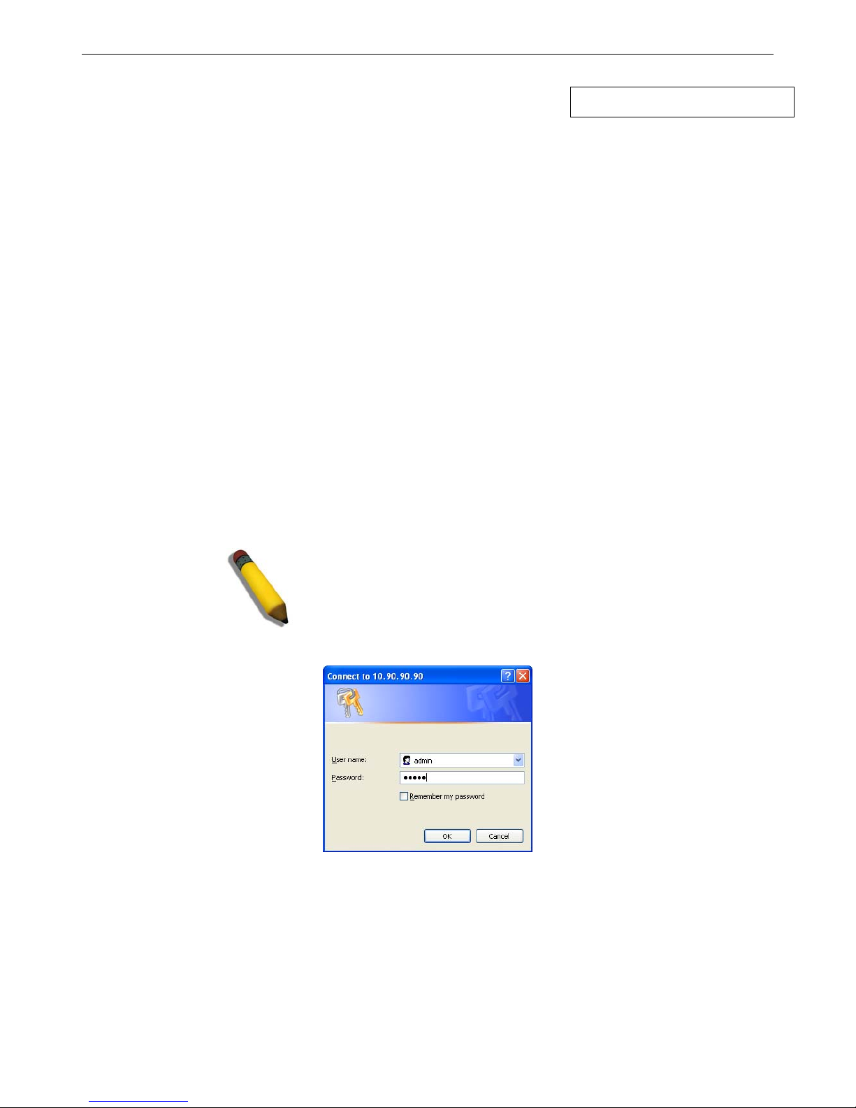
This opens the management module's user authentication window, as seen below.
Figure 1- 1. Enter Network Password window
Enter “admin” in both the User Name field and t he Password field and click OK. This will ope n the Web-based user interface.
The Switch management features available in the web-based manager are explained below.
Page 15
xStack® DGS-3200 Series Layer 2 Gigabit Ethernet Managed Switch
2
Web-based User Interface
The user i nterface provides access to various Switch configuration and management windows, allows the user to view
performance statistics, and permits graphical monitoring of the system status.
Areas of the User Interface
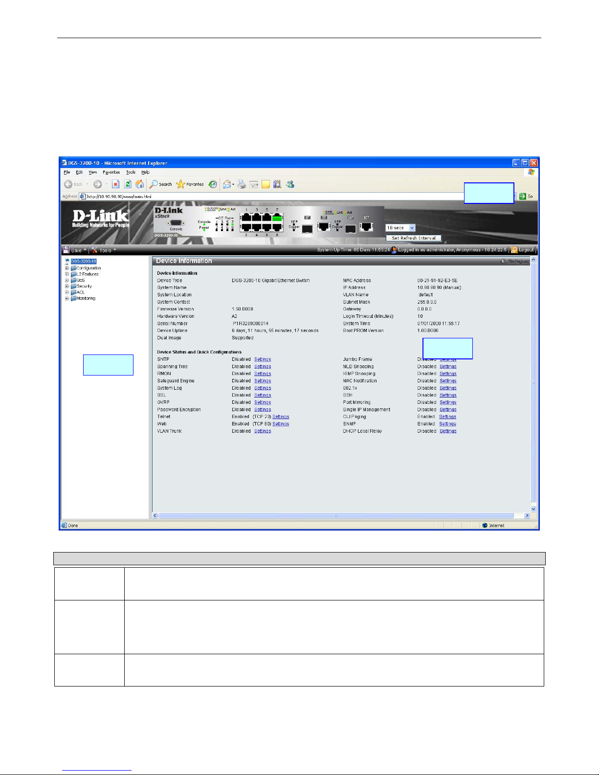
The figure below shows the user interface. Three distinct areas divide the user interface, as described in the table.
Figure 1- 2. Main Web-Manager window
Area Function
Area 1
Select the folder or window to display. Open folders and click the hyperlinked window buttons and
subfolders contained within them to display windows.
Area 2
Presents a graphical near real-time image of the front panel of the Switch. This area displays the
Switch's ports and expansion modules and shows port activity, depending on the specified mode.
Some management functions, including port monitoring are accessible here. Click the D-Link logo to
go to the D-Link website.
Area 3
Presents Switch status based on user selection and the entry of configuration data. In addition,
hyperlinks are offered for many Switch features to enable quick configuration.
Page 16

xStack® DGS-3200 Series Layer 2 Gigabit Ethernet Managed Switch
3
Web Pages
When connecting to the management mode of the Switch with a Web browser, a login screen is displayed. Enter a user name and
password to access the Switch's management mode.
Below is a list of the folders and windows available in the Web interface:
Configuration – Contains the following main folders, windows, and related windows: System Information, Serial Port Settings,
IP Address, IPv6 Interface Settings, IPv6 Route Table, IPv6 Neighbor Settings, Port Configuration, Port Settings, Port Description,
Port Error Disabled, Static ARP Setting s, User Accounts, Syst em Lo g Con figuration, System Lo g Settings, System Lo g Ho st,
System Severity Settings, DHCP/BOOTP Relay, DHCP/BOOTP Relay Global Settings, DHCP/BOOTP Relay Interface Settings,
DHCP L ocal Relay Set tings, DHC P A uto Configuration Settings, M AC Ad dress A ging Ti me, W eb Set tings, Tel net Set tings,
Password En cryption, CLI Pag ing Setting s, Firmware Information, Power Sav ing Settings, Dual Configuration Settings, SMTP
Settings, Ping Test, SNTP Settings, Time Settings, Tim e Zo ne Settings, MAC Notification Settings, MAC Notification Global
Settings, MAC Notification Port Settings, SNMP Settings, SNMP Global State Settings, SNMP Linkchange Trap Settings, SNMP
View Table, SNMP Group Table, SNMP User Table, SNMP Community Table, SNMP Host Table, SNMP v6Host Table, SNMP
Engine ID, SNMP Trap Configuration, R MON, CPU Filter L3 Con trol Pack et Se ttings, Single IP Man agement, an d Single IP
Settings, Topology, Firmware Upgrade, Configuration File Backup/Restore, Upload Log File, and SD Card FS Settings.
L2 Features – Contains the following main folders, windows, and related windows: Jumbo Frame, Egress Filter Settings, 802.1Q
VLAN, Priv ate VLAN Settin gs, 802.1v Protocol VLAN, 802 .1v Pro tocol Gro up Settings, 802 .1v Protocol VLAN Setting s,
MAC-based VLAN Settin gs, GVR P Setting s, PVID Au to Assign Settings, Po rt Tru nking, VLAN Trunk Setting s, LACP Po rt
Settings, Traffic Segmentation, IGMP Snooping, IGMP Snooping Settings, Data Driven Learning Settings, ISM VLAN Settings,
ISM Pro file Settin gs, IP Multicast Pro file Settings, Limited M ulticast Add ress Range Settin gs, Max Multicast Group Settings,
MLD Snooping Settings, P ort M irroring, L oopback Detection Settings, Spanning T ree, ST P B ridge Global Set tings, S TP Port
Settings, MST Co nfiguration Id entification, STP In stance Setti ngs, MSTP Port In formation, Forward ing & Filterin g, Unicast
Forwarding, Multicast Forwarding, and Multicast Filtering Mode.
QoS – Contains the following main folders, windows, and related windows: Bandwidth Control, Traffic Control, 802.1p Default
Priority, 802.1p User Priority, and QoS Scheduling Mechanism.
Security – Contains the following main folders, windows, and related windows: Safeguard Engine, Trusted Host, IP-MAC-Port
Binding (IMPB), IMPB Global Settings, IMPB Port Settings, IMPB Entry Settings, DHCP Snooping Entries, MAC Blocked List,
Port Security, Port Security Settings, Port Lo ck Entries, DHCP Server Scree ning, DHCP Screening Port Settings , DHCP Offer
Filtering, 802 .1X, 802.1X Settings, 802 .1X User, Au thentic RADIUS Serv er, Gu est VLAN, SSL Settin gs, SSH, SSH
Configuration, SSH Authmode an d Al gorithm Settin gs, SSH Us er Authentication Mode, Acce ss Au thentication Con trol,
Authentication Policy and Parameter Settings, Application Authentication Settings, Authentication Server Group, Authentication
Server Host, Login Method Lists, Enable Method Lists, Configure Local Enable Password, Enable Admin, MAC-based Access
Control (M AC), MAC Settings, M AC Lo cal Settin gs, Web-based Access Con trol (WAC), WAC Gl obal Setting s, WAC User
Settings, WAC Port Settings, Japanese Web-based Access Control (JWAC), JWAC Global Settings, JWAC Port Settings, JWAC
User Settings, JWAC Customize Page Language, JWAC Customize Page, Multiple Authentication, Authorization Network State
Settings, Multiple Authentication Settings, Guest VLAN, IGMP Access Control Settings, and ARP Spoofing Prevention Settings.
ACL – Contains the following m ain folders, windows, and related windows: Access Configuration Wizard, Access Profile List,
CPU Access Profile List, and Time Range Settings.
Monitoring – Contains the following main folders, windows, and related windows: Device Environment, Cable Diagnostics, CPU
Utilization, Port Utilization, Packet Size, Packets, Received (RX), UM B_cast (R X), Transmitted (TX), Errors, Received (R X),
Transmitted (TX), Port Access Con trol, RADIUS Authentication, RA DIUS Acc ount Client, Authenticator State, Authenticator
Statistics, Authenticator Session Statistics, Au thenticator Diagnostics, Browse ARP Table, Browse VLAN, Browse Router Port,
Browse MLD Router Port, Browse Session Table, IGMP Snooping Group, MLD Snooping Group, WAC A uthenticating St ate,
JWAC Host Table, MAC Address Table, System Log, and MAC Authentication State.
Save – Contains links for Save Configuration, Save Log, and Save All.
Tools – Contains the following windows: Download C onfiguration File to NV-RAM, Download Configuration File to SD Card,
Download Fir mware to NV- RAM, D ownload Firm ware to SD Ca rd, Up load Con figuration File to TFTP, Upload Lo g File to
TFTP, Reset, and Reboot System.
Page 17

xStack® DGS-3200 Series Layer 2 Gigabit Ethernet Managed Switch
4
NOTE: Be sure to configure the user name and password in the User
Accounts window before connecting the Switch to the greater network.
Page 18

xStack® DGS-3200 Series Layer 2 Gigabit Ethernet Managed Switch
5
Section 2
Configuration
Device Information
System Information
Serial Port Settings
IP Address
IPv6 Interface Settings
IPv6 Route Table
IPv6 Neighbor Settings
Port Configuration
Static ARP Settings
User Accounts
System Log Configuration
System Severity Settings
DHCP/BOOTP Relay
DHCP Local Relay Settings
DHCP Auto Configuration Settings
MAC Address Aging Time
Web Settings
Telnet Settings
Password Encryption
CLI Paging Settings
Firmware Information
Power Saving Settings
Dual Configuration Settings
SMTP Settings
Ping Test
SNTP Settings
MAC Notification Settings
SNMP Settings
CPU Filter L3 Control Packet Settings
Single IP Management
SD Card FS Settings (DGS-3200-24 only)
Page 19
xStack® DGS-3200 Series Layer 2 Gigabit Ethernet Managed Switch
6
Device Information
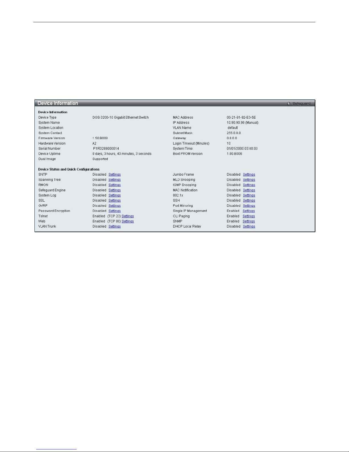
This window contains the main settings for all major functions for t he Switch. It appears automatically when you log on to the
Switch. To retu rn to the Device I nformation w indow af ter v iewing oth er windows, click th e DGS-3200-10/DGS-3200-16/
DGS-3200-24 folder. Th e Device In formation w indow show s th e Switch’s MAC Ad dress (assigned by t he fact ory an d
unchangeable), the Boot PROM Version, Firmware Version, Hardware Version, a nd many other important types of information.
This is h elpful to keep track o f PROM and firm ware upd ates and to obtain th e Switch ’s MAC address for en try in to ano ther
network device’s a ddress table, if necessary. In addition, this window displays the status of f unctions on the Switch to quickly
assess their current global status. Many functions are hyper-linked for easy access to enable quick configuration from this window.
Figure 2- 1. Device Information window
Page 20
xStack® DGS-3200 Series Layer 2 Gigabit Ethernet Managed Switch
7
System Information
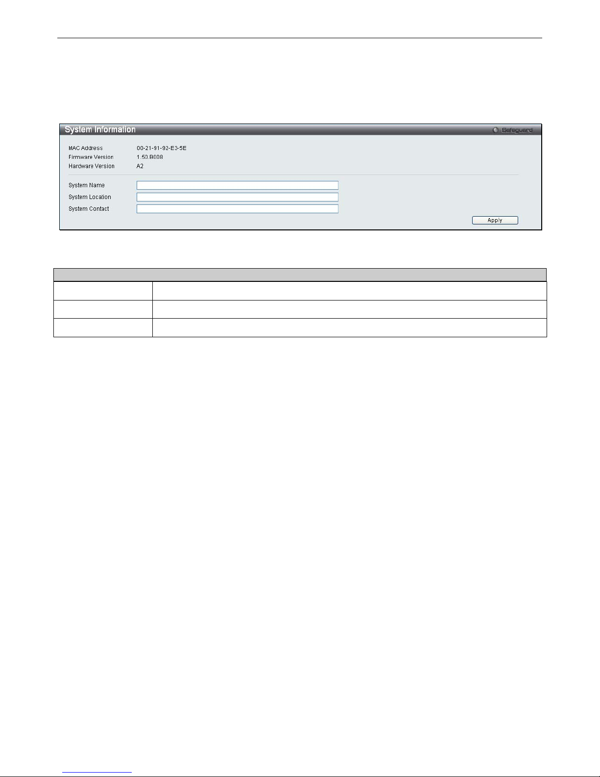
The user can enter a System Name, System Location, and System Contact to aid in defining the Switch.
To view the following window, click Configuration > System Information:
Figure 2- 2. System Information window
The fields that can be configured are described below:
Parameter Description
System Name
Enter a system name for the Switch, if desired. This name will identify it in the Switch network.
System Location
Enter the location of the Switch, if so desired.
System Contact
Enter a contact name for the Switch, if so desired.
Click
Apply
to implement changes made.
Page 21
xStack® DGS-3200 Series Layer 2 Gigabit Ethernet Managed Switch
8
Serial Port Settings
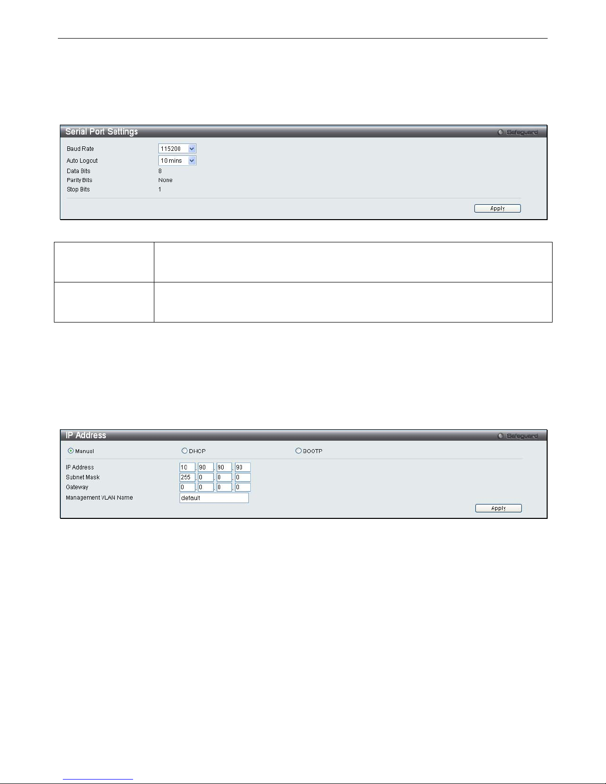
The user can adjust the Baud Rate and the Auto Logout values.
To view the following window, click Configuration > Serial Port Settings:
Figure 2- 3. Serial Port Settings window
Baud Rate This field specifies the baud rate for the serial port on the Switch. There are four possible
baud rates to choose from, 9600, 19200, 38400 and 115200. For a connection to the Switch
using the CLI interface, the baud rate must be set to 115200, which is the default setting.
Auto Logout Select the logout time used for the console interface. This automatically logs the user out after
an idle period of time, as defined. Choose from the following options: 2 mins, 5 mins, 10 mins,
15 mins or Never. The default setting is 10 mins.
Click Apply to implement changes made.
IP Address
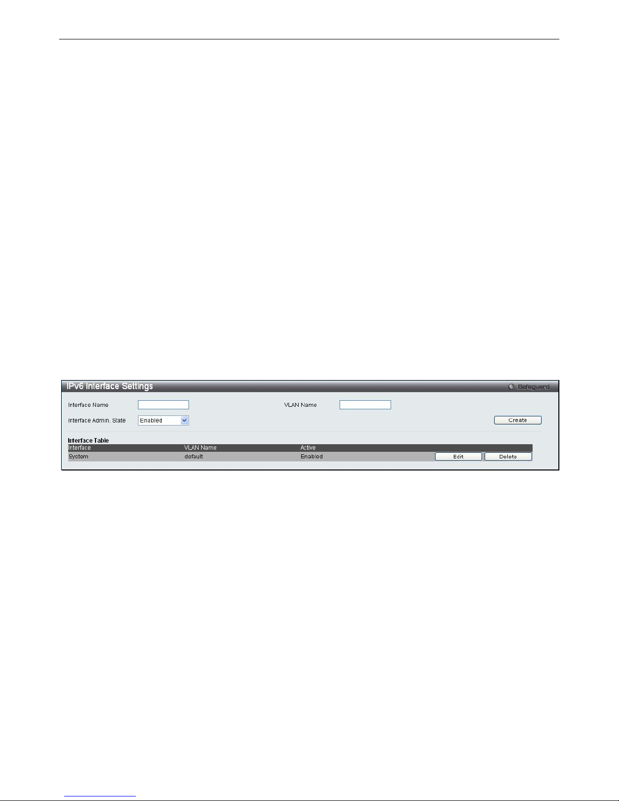
The IP ad dress m ay in itially b e set using the console in terface prior t o conn ecting to it th rough th e Eth ernet. If th e Switch I P
address ha s not y et bee n changed, read t he i ntroduction of t he DGS-3200 Series CLI Manual for m ore in formation. The Web
manager will display the Switch’s current IP settings.
To view the following window, click Configuration > IP Address:
Figure 2- 4. IP Address window
To manually assign the Switch’s IP address, subnet mask, and default gateway address:
1. Click the Manual radio button at the top of the window.
2. Enter the appropriate IP Address and Subnet Mask.
3. If accessing the Switch from a different subnet from the one it is installed on, enter the IP address of the default Gateway.
If managing the Switch fro m the subnet on which it is i nstalled, the user may leave t he default address (0.0.0.0) in this
field.
4. If the Switch has no previously configured VLANs, th e user can use the Management VLAN Nam e entitled “d efault”.
This default Management VLAN contains all of the Switch ports as members. If t he Switch has previously configured
VLANs, the user will need t o en ter t he VLAN ID of the VLAN th at contains th e port con nected to th e management
station that will access the Switch. The Switch will allow m anagement access from stations with the same VID listed
here.
Page 22

xStack® DGS-3200 Series Layer 2 Gigabit Ethernet Managed Switch
9
NOTE: The Switch’s factory default IP address is 10.90.90.90 with a
subnet mask of 255.0.0.0 and a default gateway of 0.0.0.0.
To use the DHCP or BOOTP protocols to assign the Switch an IP address, subnet mask, and default gateway address:
Use the radio button at the top of the window to choose either DHCP or BOOTP. This selects the method the Switch assigns an IP
address on the next reboot.
The following parameters may be configured or viewed:
Parameter Description
Manual
Allows the entry of an IP address, subnet mask, and a default gateway for the Switch. These fields
should be of the form xxx.xxx.xxx.xxx, where each xxx is a number (represented in decimal form)
between 0 and 255. This address should be a unique address on the network assigned for use by
the network administrator.
DHCP
The Switch will send out a DHCP broadcast request when it is powered up. The DHCP protocol
allows IP addresses, network masks, and default gateways to be assigned by a DHCP server. If
this option is set, the Switch will first look for a DHCP server to provide it with this information
before using the default or previously entered settings.
BOOTP
The Switch will send out a BOOTP broadcast request when it is powered up. The BOOTP protocol
allows IP addresses, network masks, and default gateways to be assigned by a central BOOTP
server. If this option is set, the Switch will first look for a BOOTP server to provide it with this
information before using the default or previously entered settings.
Subnet Mask
A Bitmask that determines the extent of the subnet that the Switch is on. Should be of the form
xxx.xxx.xxx.xxx, where each xxx is a number (represented in decimal) between 0 and 255. The
value should be 255.0.0.0 for a Class A network, 255.255.0.0 for a Class B network, and
255.255.255.0 for a Class C network, but custom subnet masks are allowed.
Gateway
IP address that determines where packets with a destination address outside the current subnet
should be sent. This is usually the address of a router or a host acting as an IP gateway. If your
network is not part of an intranet, or you do not want the Switch to be accessible outside your local
network, you can leave this field unchanged.
Management
VLAN Name
This allows the entry of a VLAN name from which a management station will be allowed to manage
the Switch using TCP/IP (in-band via Web manager or Telnet). Management stations that are on
VLANs other than the one entered here will not be able to manage the Switch in-band unless their
IP addresses are entered in the Trusted Host window (Security > Trusted Host). If VLANs have
not yet been configured for the Switch, the default VLAN contains all of the Switch’s ports. There
are no entries in the Trusted Host table, by default, so any management station that can connect to
the Switch can access the Switch until a management VLAN is specified or Management Station IP
addresses are assigned.
Click Apply to implement changes made.
Page 23
xStack® DGS-3200 Series Layer 2 Gigabit Ethernet Managed Switch
10
Setting the Switch’s IP Address using the Console Interface
Each Switch must be assi gned i ts own IP Address, which i s used for communication with an S NMP network manager or other
TCP/IP application (for example BOOTP, TFTP). The Switch’s default IP a ddress is 10.90.90.90. The default Switch IP address
can be changed to meet the specification of your networking address scheme.
The IP address for the Switch must be set before the Web-based manager can manage the switch. The Switch IP address can be
automatically set using BOOTP or DHCP protocols, in which case the actual address assigned to the Switch must be known. The
IP address may be set using the Command Line Interface (CLI) over the console serial port as follows:
Starting at the command line prom pt, enter the c ommands config ipif Sy stem ipaddress xxx.xxx.xxx.xxx/
yyy.yyy.yyy.yyy. Where the x’s represent the IP address t o be assigned to the IP interface nam ed System and the y’s
represent the corresponding subnet mask.
Alternatively, the user ca n enter config i pif Sy stem ipa ddress xxx.xxx.xxx.xxx/z. Whe re the x’s represent the IP
address to be assigned to the IP interface named System and the z represents the corresponding number of subnets in
CIDR notation.
The IP interface named System on the Switch can be assigned an IP address and subnet mask, which can then be used to connect a
management station to the Switch’s Telnet or Web-based management agent.
Successful entry of t he command will produce a “Success” message, indicating that the command execution was correctly. The
user may now utilize this address to c onfigure or m anage the Switch through Tel net, the Command Line Interface (CLI) or the
Web-based management (GUI).
IPv6 Interface Settings
Users can display the Switch’s current IPv6 interface settings.
To view the following window, click Configuration > IPv6 Interface Settings:
Figure 2- 5. IPv6 Interface Settings window
To configure IPv6 interface settings, enter an Interface Name, a VLAN Name, and make sure the Interface Admin. State is
Enabled. Click the
Create
button. The new entry will appear in the Interface Table at the bottom of the window.
Page 24
xStack® DGS-3200 Series Layer 2 Gigabit Ethernet Managed Switch
11
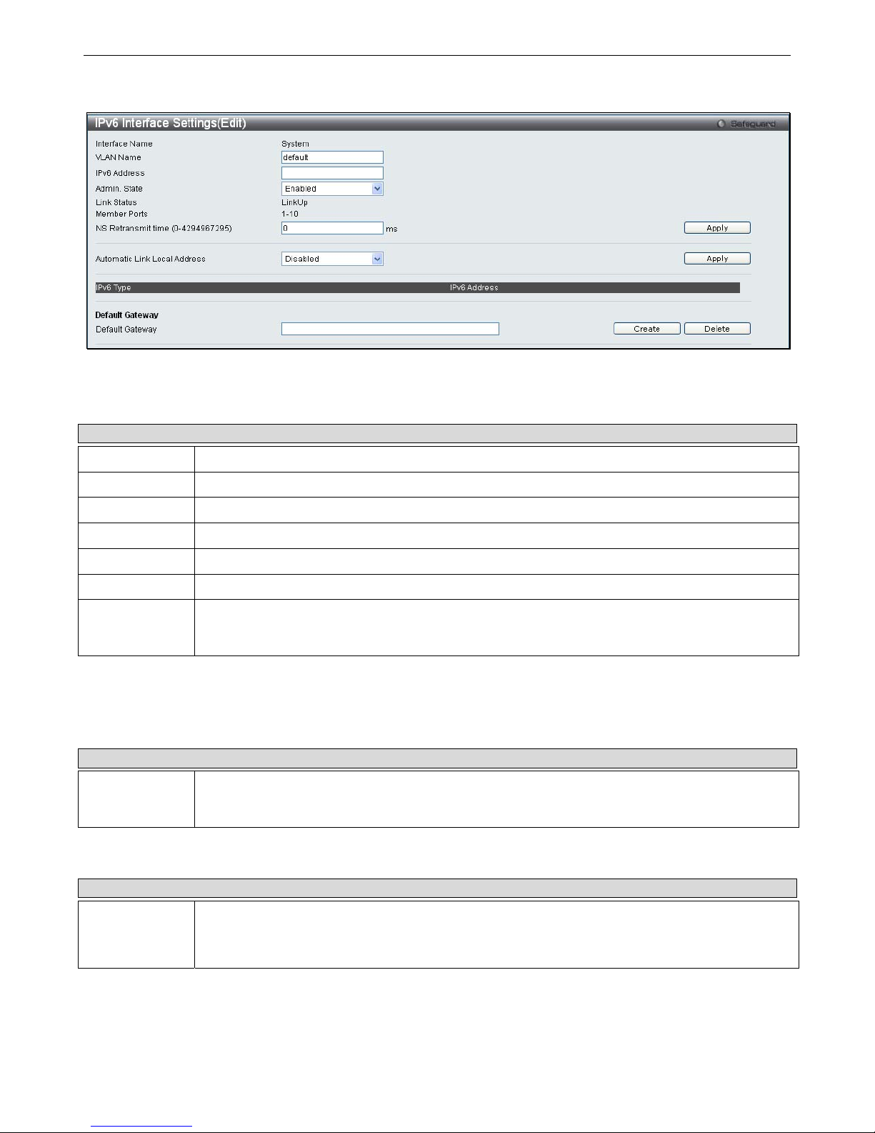
To modify an IPv6 Interface Table entry, click the corresponding Edit button. The following window opens:
Figure 2- 6. IPv6 Interface Settings (Edit) window
The IPv6 window i s divided i nto three distinct pa rts. The f ollowing parameters may b e configured or viewed at t he top of t he
window:
Parameter Description
Interface Name
The name of the IPv6 interface being modified.
VLAN Name
Enter the VLAN name of the IPv6 interface.
IPv6 Address
Enter the IPv6 address of the interface to be modified.
Admin. State
Toggle the state between Enabled and Disabled.
Link Status
Displays whether the IPv6 Interface is Up or Down.
Member Ports
Displays the port numbers that are part of the IPv6 Interface.
NS Retransmit
Time (0-
4294967295)
Enter a value between 0 and 4294967295. This is the neighbor solicitation’s retransmit timer in
milliseconds. The default is zero.
After making the desired changes, click the
Apply
button in the top section of the window.
The following parameter is used to configure the Automatic Link Local Address:
Parameter Description
Automatic Link
Local Address
Toggle between Enabled and Disabled. Enabling this is helpful when no external source of network
addressing information is available. Click the adjacent Apply button when you have finished
configuring the Automatic Link Local Address.
The following parameter is used to add/remove an IPv6 Default Gateway Address from the Switch:
Parameter Description
Default
Gateway
Enter the IPv6 address of the default gateway you want to add/remove.
Click the Create button to add the default gateway.
Click the Delete button to delete the default gateway.
Page 25
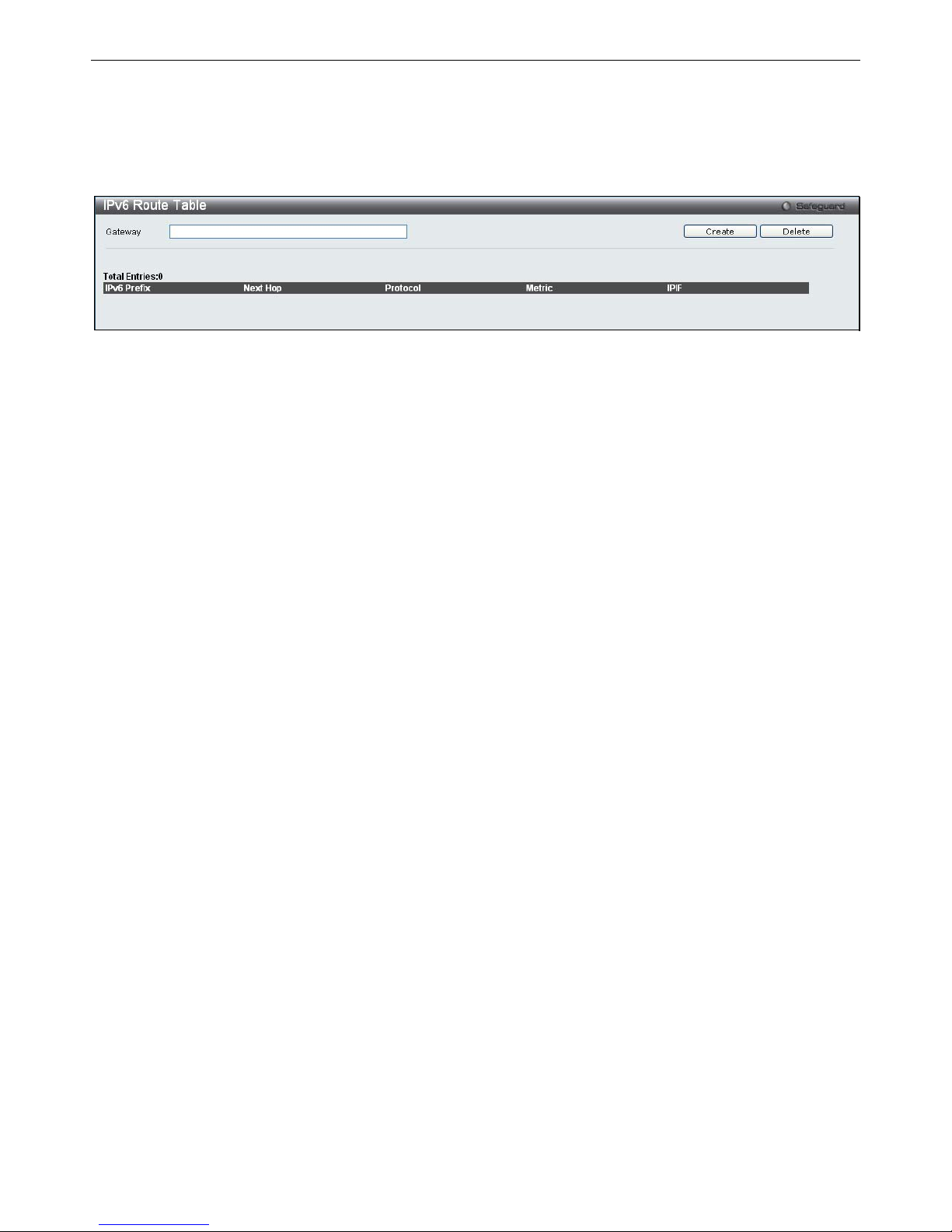
xStack® DGS-3200 Series Layer 2 Gigabit Ethernet Managed Switch
12
IPv6 Route Table
The user can configure the Switch’s IPv6 Route Table.
To view the following window, click Configuration > IPv6 Route Table:
Figure 2- 7. IPv6 Route Table window
Enter an IPv6 address in the Gateway field and click the Create button.
Page 26
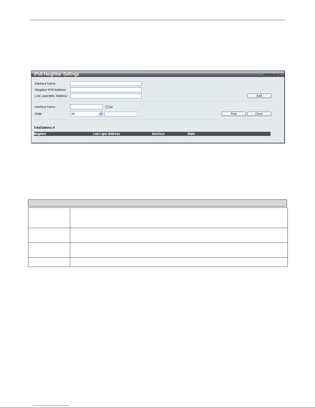
xStack® DGS-3200 Series Layer 2 Gigabit Ethernet Managed Switch
13
IPv6 Neighbor Settings
The user can configure the Switch’s IPv6 neighbor settings. The Switch’s current IPv6 neighbor settings will be displayed in the
table at the bottom of this window.
To view the following window, click Configuration > IPv6 Neighbor Settings:
Figure 2- 8. IPv6 Neighbor Settings window
Enter the Interface Name, Neighbor IPv6 Address, and the Link Layer MAC Address and then click the
Add
button. The State
can be set to All, Address, Static, or Dynamic.
To look for an IPv6 Neighbor Settings table entry, enter the Interface Name, select the desired State in the middle section of this
window, and then click the
Find
button.
To delete all the entries being displayed on the table at the bottom of this window, click the
Clear
button.
The following parameters may be configured or viewed:
Parameter Description
Interface Name
Enter the name of the IPv6 neighbor. To search for all the current interfaces on the Switch, go to
the second Interface Name field in the middle part of the window, tick the All check box, and then
click the Find button.
Neighbor IPv6
Address
Enter the neighbor IPv6 address.
Link Layer MAC
Address
Enter the link layer MAC address.
State
Use the drop-down menu to select All, Address, Static, or Dynamic.
Page 27
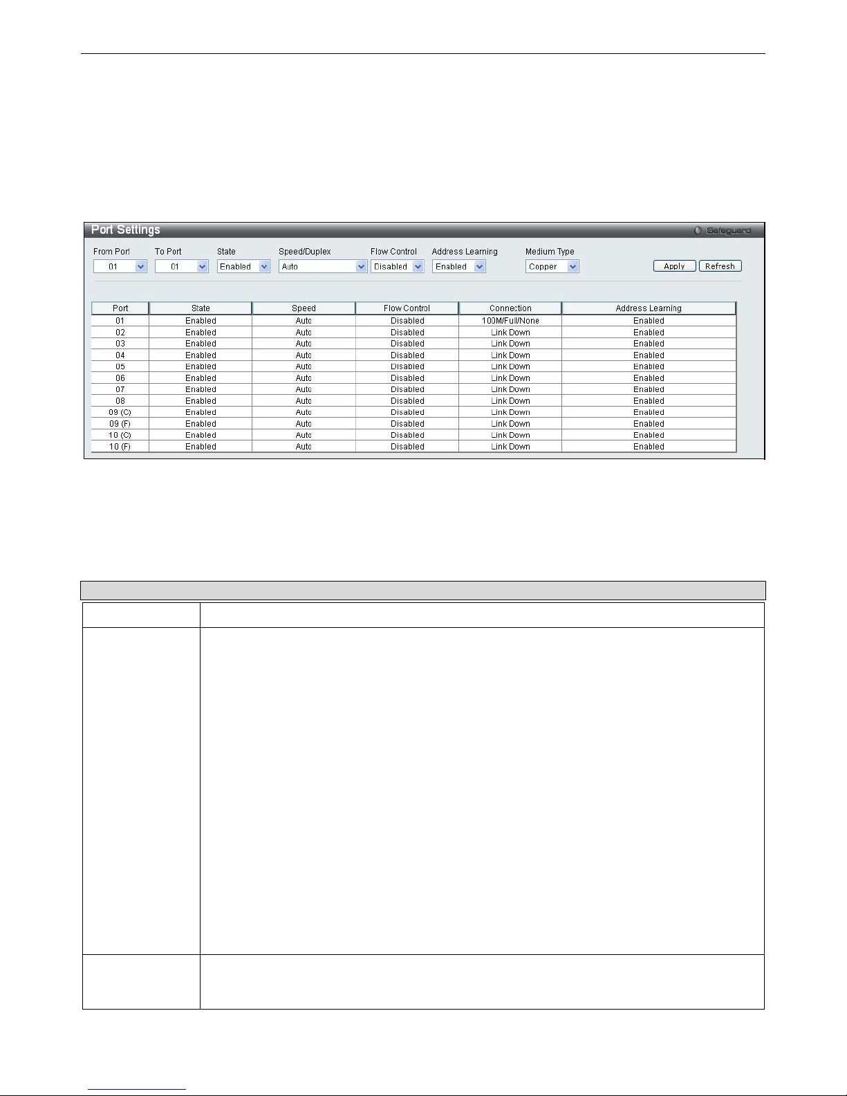
xStack® DGS-3200 Series Layer 2 Gigabit Ethernet Managed Switch
14
Port Configuration
The Port Configuration folder contains three windows: Port Settings, Port Description, and Port Error Disabled.
Port Settings
To view the following window, click Configuration > Port Configuration > Port Settings:
Figure 2- 9. Port Settings window
To configure switch ports:
1. Choose the port or sequential range of ports using the From Port and To Port drop-down menus.
2. Use the remaining drop-down menus to configure the parameters described below:
The following parameters may be configured or viewed:
Parameter Description
State
Toggle the State field to either enable or disable a given port or group of ports.
Speed/Duplex
Toggle the Speed/Duplex field to either select the speed and duplex/half-duplex state of the
port. Auto denotes auto-negotiation between 10 and 100 Mbps devices, in full- or half-duplex.
The Auto setting allows the port to automatically determine the fastest settings the device the
port is connected to can handle, and then to use those settings. The other options are 10M
Half, 10M Full, 100M Half, 100M Full, 1000M Full_Master, 1000M Full_Slave, and 1000M Full.
There is no automatic adjustment of port settings with any option other than Auto.
The Switch allows the user to configure three types of gigabit connections; 1000M Full_Master,
1000M Full_Slave, and 1000M Full. Gigabit connections only support full duplex connections
and take on certain characteristics that are different from the other choices listed.
The 1000M Full_Master and 1000M Full_Slave parameters refer to connections running a
1000BASE-T cable for connection between the Switch port and other device capable of a
gigabit connection. The master setting (1000M Full_Master) will allow the port to advertise
capabilities related to duplex, speed and physical layer type. The master setting will also
determine the master and slave relationship between the two connected physical layers. This
relationship is necessary for establishing the timing control between the two physical layers.
The timing control is set on a master physical layer by a local source. The slave setting (1000M
Full_Slave) uses loop timing, where the timing comes from a data stream received from the
master. If one connection is set for 1000M Full_Master, the other side of the connection must
be set for 1000M Full_Slave. Any other configuration will result in a link down status for both
ports.
Flow Control
Displays the flow control scheme used for the various port configurations. Ports configured for
full-duplex use 802.3x flow control, half-duplex ports use backpressure flow config, and Auto
ports use an automatic selection of the two. The default is Disabled.
Page 28
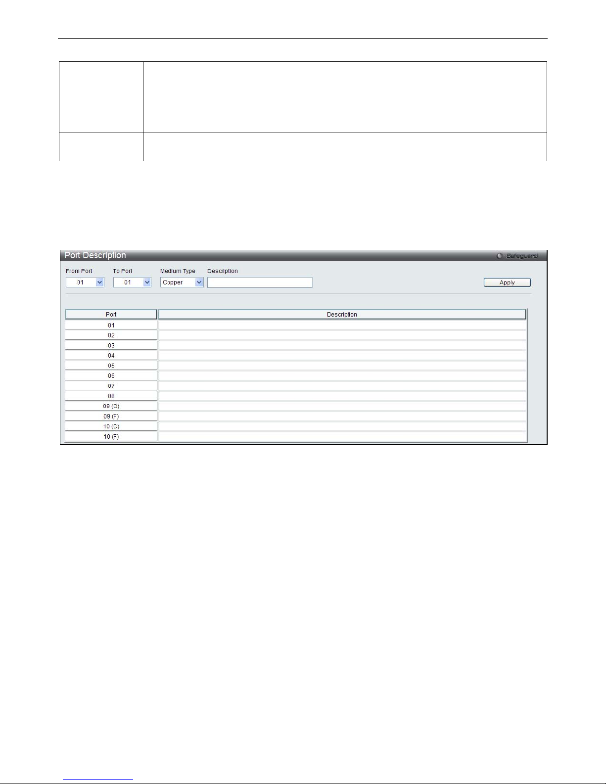
xStack® DGS-3200 Series Layer 2 Gigabit Ethernet Managed Switch
15
Address
Learning
Enable or disable MAC address learning for the selected ports. When Enabled, destination and
source MAC addresses are automatically listed in the forwarding table. When address learning
is Disabled, MAC addresses must be manually entered into the forwarding table. This is
sometimes done for reasons of security or efficiency. See the section on Forwarding/Filtering
for information on entering MAC addresses into the forwarding table. The default setting is
Enabled.
Medium Type
If configuring the Combo ports, this defines the type of transport medium to be used, whether
Copper or Fiber.
Click Apply to implement the new settings on the Switch.
Port Description
The Switch supports a port description feature where the user may name various ports.
To view the following window, click Configuration > Port Configuration > Port Description:
Figure 2- 10. Port Description window
Use the From Port and To Port drop-down menu to choose a port or range of ports to describe. Users may then enter a description
for the chosen port(s). If configuring the Combo ports, the Medium Type defines the type of transport medium to be used, whether
Copper or Fiber.
Click Apply to set the descriptions in the Port Description window.
Page 29
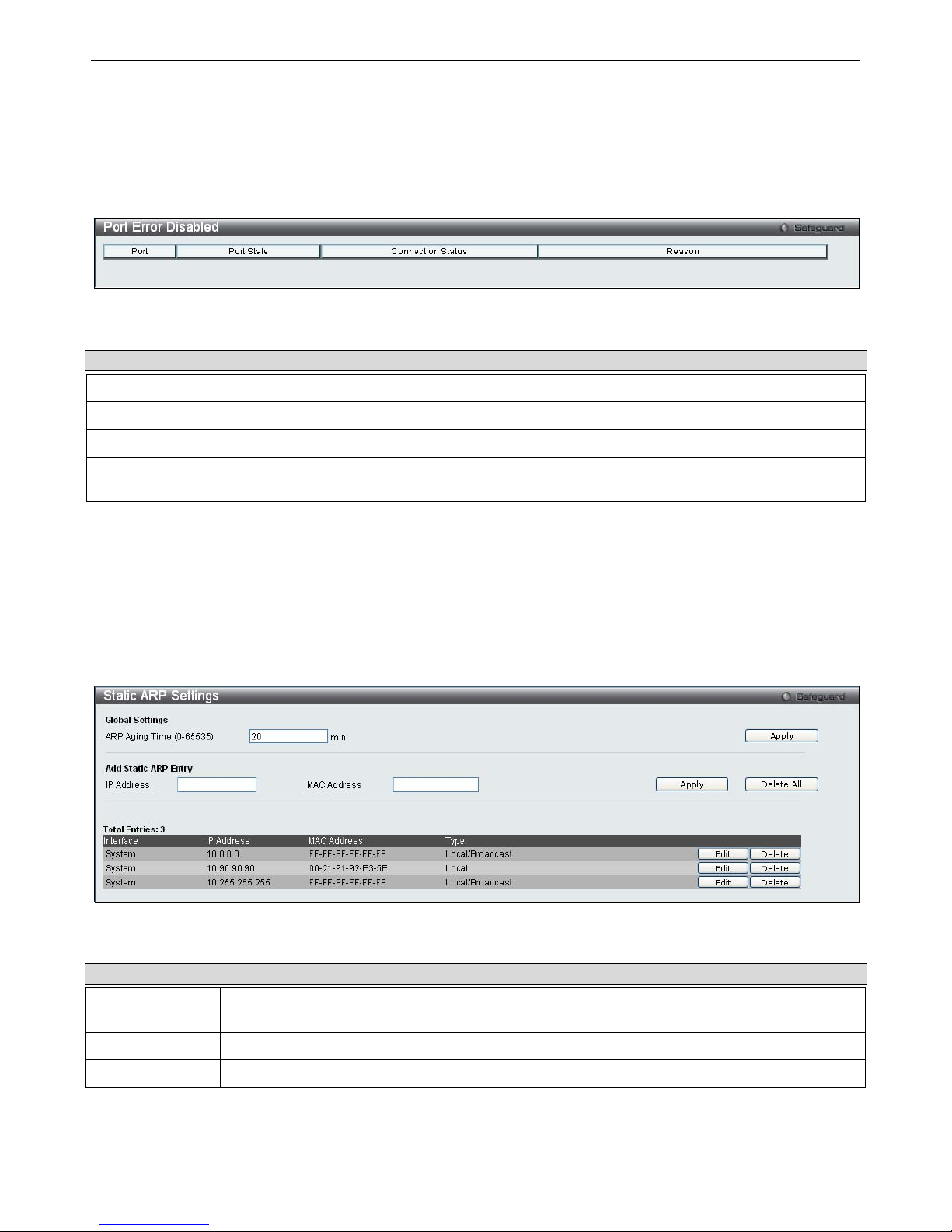
xStack® DGS-3200 Series Layer 2 Gigabit Ethernet Managed Switch
16
Port Error Disabled
The following window will display the information about ports that have had their connection status disabled, for reasons such as
storm control or link down status.
To view the following window, click Configuration > Port Configuration > Port Error Disabled:
Figure 2- 11. Port Error Disabled window
The following parameters are displayed:
Parameter Description
Port
Displays the port that has been error disabled.
Port State
Describes the current running state of the port, whether enabled or disabled.
Connection Status
This field will read the uplink status of the individual ports, whether enabled or disabled.
Reason
Describes the reason why the port has been error-disabled, such as it has become a
shutdown port for storm control.
Static ARP Settings
The Address Resolution P rotocol i s a T CP/IP p rotocol t hat con verts IP a ddresses into physical addresses. Th is tab le allo ws
network managers to view, define, modify, and delete ARP information for specific devices.
Static entries can be defined in the ARP table. When static entries are defined, a permanent entry is entered and is used to translate
IP addresses to MAC addresses.
To view the following window, click Configuration > Static ARP Settings:
Figure 2- 12. Static ARP Settings window
The following parameters may be configured or viewed:
Parameter Description
ARP Aging Time
(0-65535)
The ARP entry age-out time, in seconds. The default is 20 minutes.
IP Address
The IP address of the ARP entry.
MAC Address
The MAC address of the ARP entry.
After entering a global ARP Aging Time in seconds, click Apply to allow it to take effect. The default value is 20 seconds.
Page 30

xStack® DGS-3200 Series Layer 2 Gigabit Ethernet Managed Switch
17
After entering the IP Address and MAC Address of the Static ARP entry, click Apply to implement the new entry. To completely
clear the static ARP entries, click the Delete All button.
To modify a st atic ARP en try, click the Edit button located on the right side of the en try in the ARP table at th e bottom of the
window.
To delete a static ARP entry, click the Delete button located on the right side of the entry in the static ARP tab le at the bottom of
the window.
Page 31
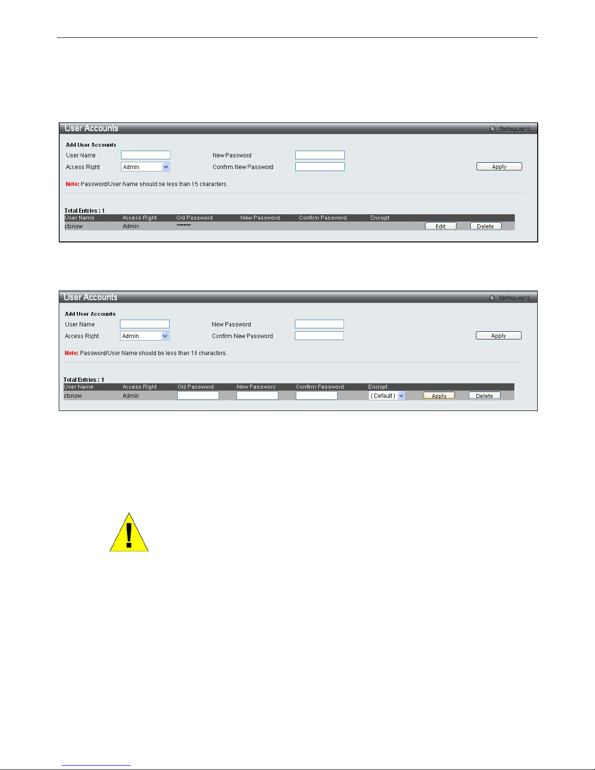
xStack® DGS-3200 Series Layer 2 Gigabit Ethernet Managed Switch
18
User Accounts
The Switch allows the control of user privileges.
To view the following window, click Configuration > User Accounts:
Figure 2- 13. User Accounts window
To add a new user, type in a User Name and New Password and retype the same password in the Confirm New Password field.
Choose the level of privilege (Admin or User) from the Access Right drop-down menu.
Figure 2- 14. User Accounts window (Edit)
Modify or delete an e xisting user account in the table at the bottom of the window. To delete the user account, click the Delete
button. To change t he password, cl ick the Edit bu tton next to the entry in the table at the bottom of the window. Enter an Old
Password, New Password, and retype the new password in the Confirm Password field offered, use the drop-down menu to select
the type of encryption desired (Plain Text or Sha 1), and then click Apply. The level of privilege (Admin or User) can be viewed
in the Access Right column in the table at the bottom of the window.
NOTICE: In case of lost passwords or password corruption, please refer to the
Appendix D, “Password Recovery Procedure,” which will guide you through the
steps necessary to resolve this issue.
Admin and User Privileges
There are two levels of user privileges, Admin and User. Some menu selections available to users with Admin privileges may not
be available to those with User privileges.
The following table summarizes the Admin and User privileges:
Page 32
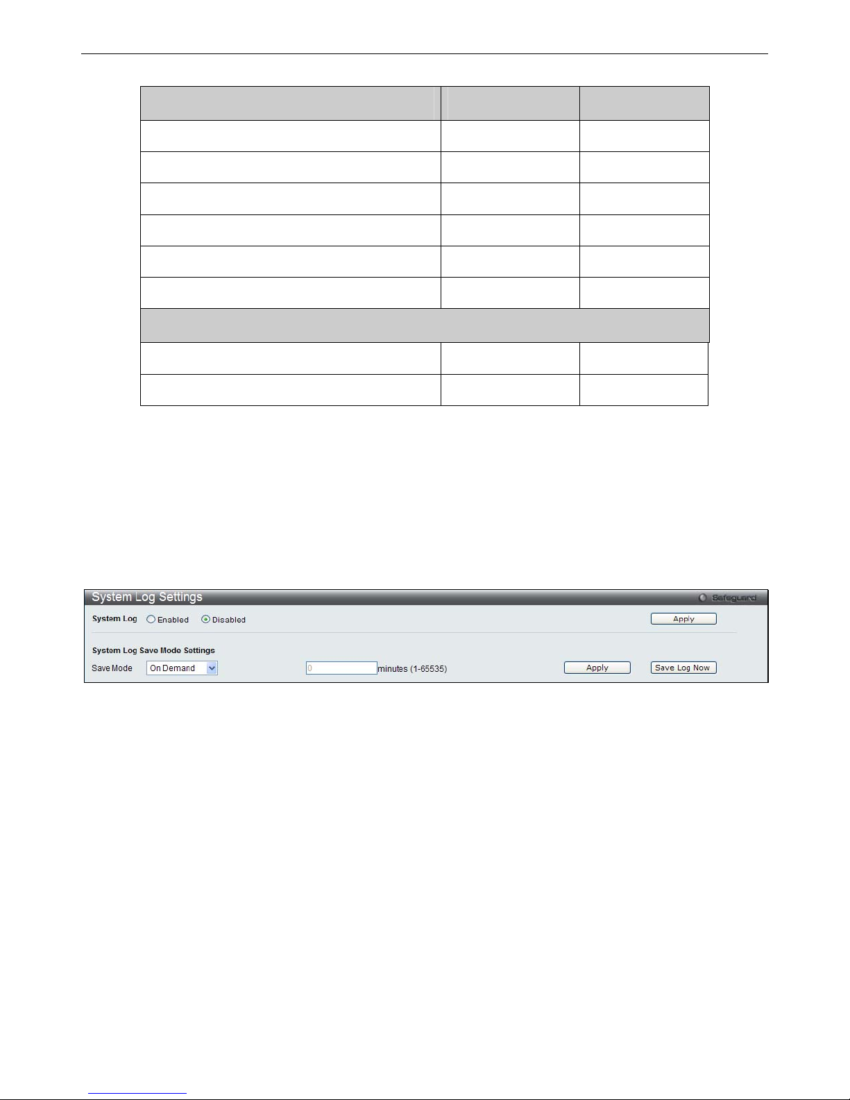
xStack® DGS-3200 Series Layer 2 Gigabit Ethernet Managed Switch
19
Management Admin User
Configuration Yes Read-only
Network Monitoring Yes Read-only
Community Strings and Trap Stations Yes Read-only
Update Firmware and Configuration Files Yes No
System Utilities Yes No
Factory Reset Yes No
User Account Management
Add/Update/Delete User Accounts Yes No
View User Accounts Yes No
System Log Configuration
The System Log Configuration folder contains two windows: System Log Settings and System Log Host.
System Log Settings
The Switch allows users to choose a method for which to save the switch log to the flash memory of the Switch.
To view the following window, click Configuration > System Log Configuration > System Log Settings:
Figure 2- 15. System Log Settings window
Use the drop-down menu to choose the method for saving the switch log to the flash memory. The user has three options:
Time Interval – Users who choose this method can configure a time interval by which the Switch will save the log files,
in the box adjacent to this configuration field. The user may set a time between 1 and 65535 minutes.
On Demand – Users who choose this method will only save log files when they manually tell the Switch to do so, either
using the Save Log link in the Save folder or clicking the Save Log Now button on this window.
Log Trigger – Users who choose this method will have log files saved to the Switch every time a log event occurs on the
Switch.
The d efault setting is On Demand. Click Apply t o sa ve cha nges m ade. C lick Save L og Now to immediately sav e l og files
currently on the switch.
Page 33

xStack® DGS-3200 Series Layer 2 Gigabit Ethernet Managed Switch
20
System Log Host
The Switch can send Syslog messages to up to four designated servers using the System Log Server.
To view the following window, click Configuration > System Log Configuration > System Log Host:
Figure 2- 16. System Log Host window
The following parameters may be configured or viewed:
Parameter Description
Host ID
Syslog server settings index (1 to 4).
Host IP Address
The Ipv4 address of the Syslog server.
UDP Port (514 or
6000-65535)
Type the UDP port number used for sending Syslog messages. The default is 514.
Severity
This drop-down menu allows you to select the level of messages that will be sent. The
options are Warning, Informational, and All.
Facility
Use the drop-down menu to select Local 0, Local 1, Local 2, Local 3, Local 4, Local 5, Local
6, or Local 7.
Status
Choose Enabled or Disabled to activate or deactivate.
To set t he System Lo g Server co nfiguration, click Apply. To delete an en try from th e System Lo g Ho st List tab le, click t he
corresponding Delete button next to the entry.
System Severity Settings
The Switch can be configured to allow alerts be logged or sent as a trap to an SNMP a gent or both. The level at whi ch the alert
triggers either a log entry or a trap message can be set as well. Use the System Severity Settings window to set the criteria fo r
alerts. The current settings are displayed below the System Severity Table.
To view the following window, click Configuration > System Severity Settings:
Figure 2 - 17. System Severity Settings window
The following parameters may be configured or viewed:
Page 34

xStack® DGS-3200 Series Layer 2 Gigabit Ethernet Managed Switch
21
Parameter Description
System Severity
Choose how the alerts are used from the drop-down menu. Select Log to send the alert of the
Severity Type configured to the Switch’s log for analysis. Choose Trap to send it to an SNMP
agent for analysis, or select All to send the chosen alert type to an SNMP agent and the
Switch’s log for analysis.
Severity Level
Choose what level of alert will trigger sending the log entry or trap message as defined by the
Severity Name. Select Critical to send only critical events to the Switch’s log or SNMP agent.
Choose Warning to send critical and warning events to the Switch’s log or SNMP agent.
Select Information to send informational, warning, and critical events to the Switch’s log or
SNMP agent.
Click Apply to implement the new System Severity Settings.
DHCP/BOOTP Relay
The DHCP/BOOTP Rela y folder contains two windows: DHCP/BOOTP Rela y Global Se ttings and DHCP/BOOTP Rel ay
Interface Settings.
DHCP/BOOTP Relay Global Settings
Users can enable and configure DHCP/BOOTP Relay Global Settings. The relay hops count limit allows the maximum number of
hops (routers) that t he DHCP/BOOTP messages can be relayed through to be set. If a packet’s hop count is m ore than the hop
count limit, the packet is dropped. The range is between 1 and 16 hops, with a default value of 4. The relay time threshold sets the
minimum time (in seco nds) that the Switch will wait before forwarding a BOOTREQUEST packet. If the value in the seconds
field of the packet is less th an the relay time threshold, the p acket will be dropped. The ran ge is between 0 and 65,535 seconds,
with a default value of 0 seconds.
To view the following window, click Configuration > DHCP/BOOTP Relay > DHCP/BOOTP Relay Global Settings:
Figure 2 - 18. DHCP/ BOOTP Relay Global Settings window
The following parameters may be configured or viewed:
Parameter Description
DHCP/BOOTP Relay
State
This field can be toggled between Enabled and Disabled using the drop-down menu. It is
used to enable or disable the DHCP/BOOTP Relay service on the Switch. The default is
Disabled.
DHCP/BOOTP Relay
Hops Count Limit (1-
16)
This field allows an entry between 1 and 16 to define the maximum number of router hops
DHCP/BOOTP messages can be forwarded. The default hop count is 4.
DHCP/BOOTP Relay
Time Threshold (0-
65535)
Allows an entry between 0 and 65535 seconds, and defines the maximum time limit for
routing a DHCP/BOOTP packet. If a value of 0 is entered, the Switch will not process the
value in the seconds field of the BOOTP or DHCP packet. If a non-zero value is entered,
the Switch will use that value, along with the hop count to determine whether to forward a
given BOOTP or DHCP packet.
Page 35

xStack® DGS-3200 Series Layer 2 Gigabit Ethernet Managed Switch
22
DHCP Relay Agent
Information Option 82
State
This field can be toggled between Enabled and Disabled using the drop-down menu. It is
used to enable or disable the DHCP Relay Agent Information Option 82 on the Switch. The
default is Disabled.
Enabled –When this field is toggled to Enabled, the relay agent will insert and remove
DHCP relay information (option 82 field) in messages between DHCP servers and clients.
When the relay agent receives the DHCP request, it adds the option 82 information, and
the IP address of the relay agent (if the relay agent is configured), to the packet. Once the
option 82 information has been added to the packet it is sent on to the DHCP server. When
the DHCP server receives the packet, if the server is capable of option 82, it can implement
policies like restricting the number of IP addresses that can be assigned to a single rem ote
ID or circuit ID. Then the DHCP server echoes the option 82 field in the DHCP reply. The
DHCP server unicasts the reply back to the relay agent if the request was relayed to the
server by the relay agent. The switch verifies that it originally inserted the option 82 data.
Finally, the relay agent removes the option 82 field and forwards the packet to the switch
port that connects to the DHCP client that sent the DHCP request.
Disabled- When the field is toggled to Disabled, the relay agent will not insert and remove
DHCP relay information (option 82 field) in messages between DHCP servers and clients,
and the check and policy settings will have no effect.
DHCP Relay Agent
Information Option 82
Check
This field can be toggled between Enabled and Disabled using the drop-down menu. It is
used to enable or disable the Switches ability to check the validity of the packet’s option 82
field.
Enabled – When the field is toggled to Enabled, the relay agent will check the validity of the
packet’s option 82 field. If the switch receives a packet that contains the option 82 field from
a DHCP client, the switch drops the packet because it is invalid. In packets received from
DHCP servers, the relay agent will drop invalid messages.
Disabled – When the field is toggled to Disabled, the relay agent will not check the validity
of the packet’s option 82 field.
DHCP Relay Agent
Information Option 82
Policy
This field can be toggled between Replace, Drop, and Keep by using the drop-down menu.
It is used to set the Switches policy for handling packets when the DHCP Relay Agent
Information Option 82 Check is set to Disabled. The default is Replace.
Replace – The option 82 field will be replaced if the option 82 fi eld already exists in the
packet received from the DHCP client.
Drop – The packet will be dropped if the option 82 field already exists in the packet
received from the DHCP client.
Keep – The option 82 field will be retained if the option 82 field already exists in the packet
received from the DHCP client.
Click Apply to implement any changes that have been made.
NOTE: If the Switch receives a packet that contains the option 82 field from a DHCP
client and the information-checking feature is enabled, the Switch drops the packet
because it is invalid. However, in some instances, users may configure a client with the
option 82 field. In this situation, disable the information check feature so that the Switch
does not remove the option 82 field from the packet. Users may configure the action that
the Switch takes when it receives a packet with existing option 82 information by
configuring the DHCP Agent Information Option 82 Policy.
Page 36

xStack® DGS-3200 Series Layer 2 Gigabit Ethernet Managed Switch
23
Implementation of DHCP Relay Agent Information Option 82
The config dhcp_relay opti on_82 command configures the DHCP relay ag ent information option 82 setting of the Switch . The
formats for the circuit ID sub-option and the remote ID sub-option are as follows:
NOTE: For the circuit ID sub-option of a standalone switch, the module field is always zero.
Circuit ID sub-option format:
1. 2. 3. 4. 5. 6. 7.
1 6 0 4 VLAN Module Port
1 byte 1 byte 1 byte 1 byte 2 bytes 1 byte 1 byte
1. Sub-option type
2. Length
3. Circuit ID type
4. Length
5. VLAN: the incoming VLAN ID of DHCP client packet.
6. Module: For a standalone switch, the Module is always 0; for a stackable switch, the Module is the Unit ID.
7. Port: The incoming port number of the DHCP client packet, the port number starts from 1.
Remote ID sub-option format:
1. 2. 3. 4. 5.
2 8 0 6 MAC address
1 byte 1 byte 1 byte 1 byte 6 bytes
1. Sub-option type
2. Length
3. Remote ID type
4. Length
5. MAC address: The Switch’s system MAC address.
Figure 2 - 19. Circuit ID and Remote ID Sub-option Format
Page 37
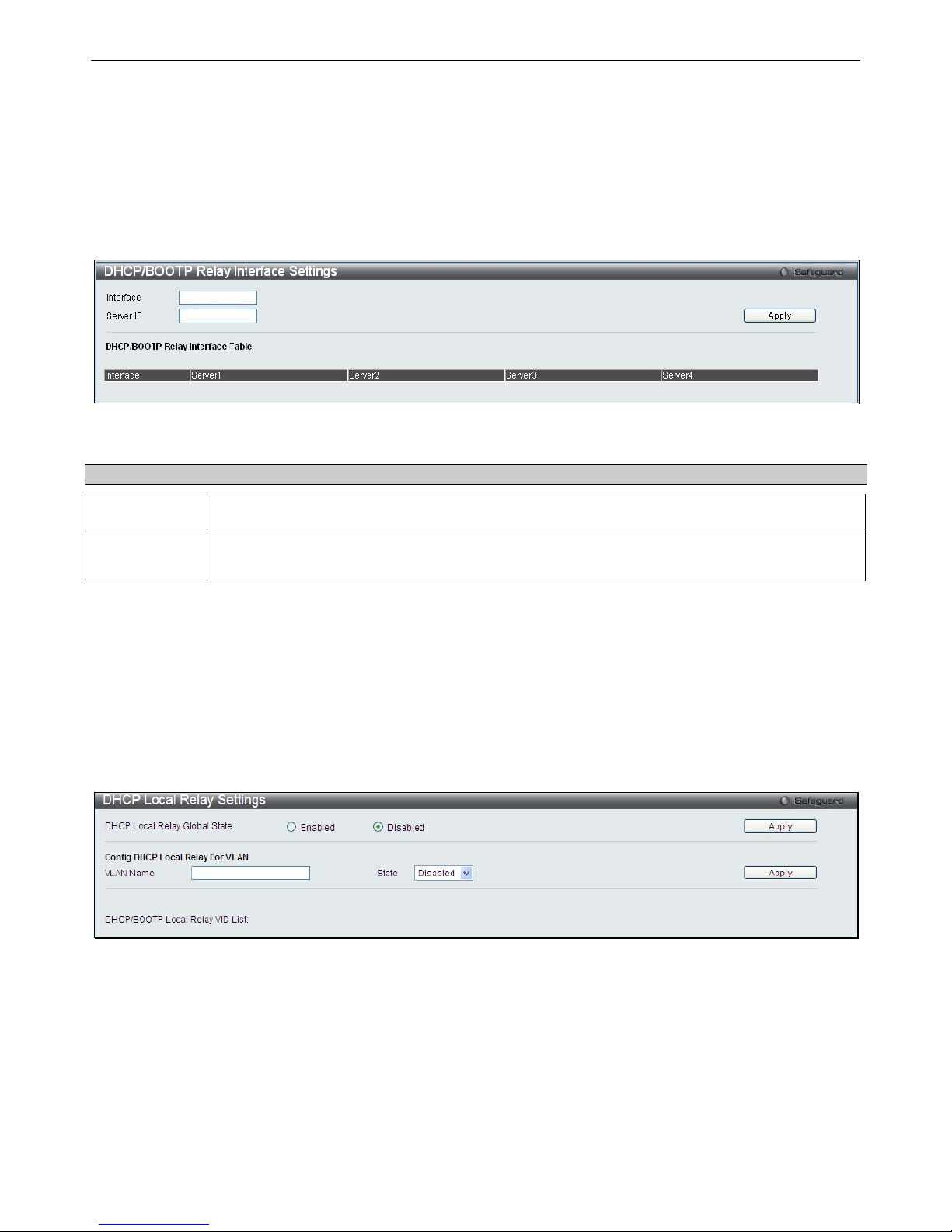
xStack® DGS-3200 Series Layer 2 Gigabit Ethernet Managed Switch
24
DHCP/BOOTP Relay Interface Settings
Users can set up a serve r, by IP address, for relaying DHCP/BOOTP information to the Switch. Th e user may enter a previ ously
configured IP interface on the Switch th at will be connected d irectly to the DHCP/BOOTP serv er using this window. Properly
configured settings will be di splayed in the DHCP/BOOTP Re lay Interface Table at t he bottom of t he window, once the user
clicks the Apply button. The user may add up to four server IPs per IP interface on the Switch. Entries may be deleted by clicking
the corresponding Delete button.
To view the following window, click Configuration > DHCP/BOOTP Relay > DHCP/BOOTP Relay Interface Settings:
Figure 2 - 20. DHCP/BOOTP Relay Interface Settings window
The following parameters may be configured or viewed:
Parameter Description
Interface
The IP interface on the Switch that will be connected directly to the Server.
Server IP
Enter the IP address of the DHCP/BOOTP server. Up to four server IPs can be configured per IP
Interface.
Click Apply to include this Server IP.
DHCP Local Relay Settings
The DHCP local relay settin gs allows t he user to add option 82 into DHCP request packets when the DHCP clien t gets an IP
address from the same VLAN. If the DHCP local relay settings are not configured, the Switch will flood the packets to the VLAN.
In order to add option 82 into the DHCP request packets, the DHCP local relay settings and the state of the Global VLAN need to
be enabled.
To view the following window, click Configuration > DHCP Local Relay Settings:
Figure 2 - 21. DHCP Local Relay Settings window
The following parameters may be configured or viewed:
Page 38

xStack® DGS-3200 Series Layer 2 Gigabit Ethernet Managed Switch
25
Parameter Description
DHCP Local
Relay Global
State
Enable or disable the DHCP Local Relay Global State. The default is Disabled.
VLAN Name
This is the VLAN Name that identifies the VLAN the user wishes to apply the DHCP Local Relay
operation.
State
Enable or disable the Config DHCP Local Relay for VLAN state.
DHCP/BOOTP
Local Relay
VID List
This is a list of VLAN IDs the user wishes to apply the DHCP/BOOTP Local Relay operations.
Click Apply to implement the new DHCP Local Relay Settings.
DHCP Auto Configuration Settings
This window is u sed to en able th e DHCP auto configuration feature on th e Switch . When enabled, the Switch is instructed to
receive a configuration file from a TFTP server, which will set the Switch to become a DHCP client automatically on boot-up. To
employ t his method, t he DHCP se rver must be set u p t o deliver t he T FTP ser ver I P a ddress and co nfiguration file n ame
information in the DHCP reply packet. The TFTP server must be up and running and hold the necessary configuration file stored
in its base directory when the request is received from the Switch. For more information about loading a configuration file for use
by a cl ient, se e t he D HCP s erver a nd/or T FTP se rver software instruct ions. T he us er may also consult the Upload L og File
window description located in the Tools section of this manual.
If the Switch is unable to complete the DHCP au to configuration, the previously saved configuration file present in the Switch’s
memory will be used.
To view the following window, click Configuration > DHCP Auto Configuration Settings:
Figure 2 - 22. DHCP Auto Configuration Settings window
To enable the DHCP Auto Configuration State, click the Enabled radio button and then click the Apply button.
The following parameter may be configured or viewed:
Parameter Description
Auto
Configuration
State
Enable or disable the Switch’s DHCP auto configuration feature. When enabled, the Switch is
instructed to receive a configuration file from a TFTP server, which will set the Switch to become
a DHCP client automatically on boot-up. To employ this method, the DHCP server must be set
up to deliver the TFTP server IP address and configuration file name information in the DHCP
reply packet. The TFTP server must be up and running and hold the necessary configuration file
stored in its base directory when the request is received from the Switch.
Click Apply to set the DHCP Auto Configuration State.
Page 39
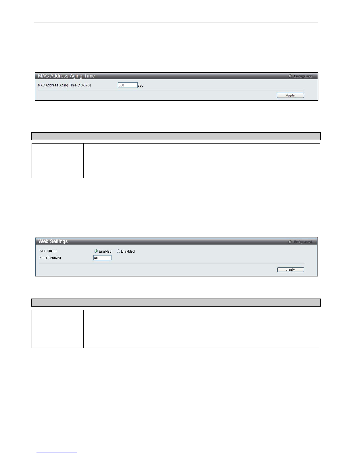
xStack® DGS-3200 Series Layer 2 Gigabit Ethernet Managed Switch
26
MAC Address Aging Time
Users can configure the MAC Address aging time on the Switch.
To view the following window, click Configuration > MAC Address Aging Time:
Figure 2 – 23. MAC Address Aging Time window
Enter a value between 10 and 875 seconds.
The following parameter may be configured or viewed:
Parameter Description
MAC Address
Aging Time (10-
875)
This field specifies the length of time a learned MAC Address will remain in the forwarding table
without being accessed (that is, how long a learned MAC Address is allowed to remain idle). To
change this, type in a different value to represent the MAC address age-out time in seconds.
The MAC Address Aging Time can be set to any value between 10 and 875 seconds. The
default setting is 300 seconds.
Click Apply to set the MAC Address Aging Time.
Web Settings
Users can configure the Web settings on the Switch.
To view the following window, click Configuration > Web Settings:
Figure 2 – 24. Web Settings window
The following parameters may be configured or viewed:
Parameter Description
Web Status
Web-based management is Enabled by default. If you choose to disable this by clicking
Disabled, you will lose the ability to configure the system through the web interface as soon as
these settings are applied.
Port (1-65535)
The TCP port number used for Web-based management of the Switch. The “well-known” TCP
port for the Web protocol is 80.
Click Apply to set the web settings.
Page 40
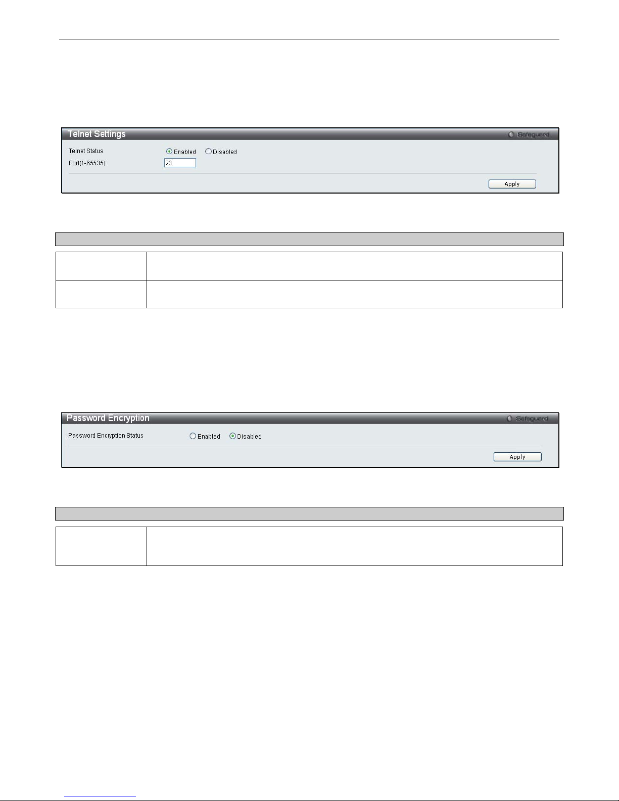
xStack® DGS-3200 Series Layer 2 Gigabit Ethernet Managed Switch
27
Telnet Settings
Users can configure Telnet Settings on the Switch.
To view the following window, click Configuration > Telnet Settings:
Figure 2 – 25. Telnet Settings window
The following parameters may be configured or viewed:
Parameter Description
Telnet Status
Telnet configuration is Enabled by default. If you do not want to allow configuration of the
system through Telnet choose Disabled.
Port (1-65535)
The TCP port number used for Telnet management of the Switch. The “well-known” TCP port for
the Telnet protocol is 23.
Click Apply to set the Telnet setting.
Password Encryption
Users can configure Password Encryption on the Switch.
To view the following window, click Configuration > Password Encryption:
Figure 2 – 26. Password Encryption window
The following parameter may be configured or viewed:
Parameter Description
Password
Encryption
Status
Password encryption is Disabled by default. To enable password encryption, click the Enabled
radio button.
Click Apply to set the password encryption.
Page 41
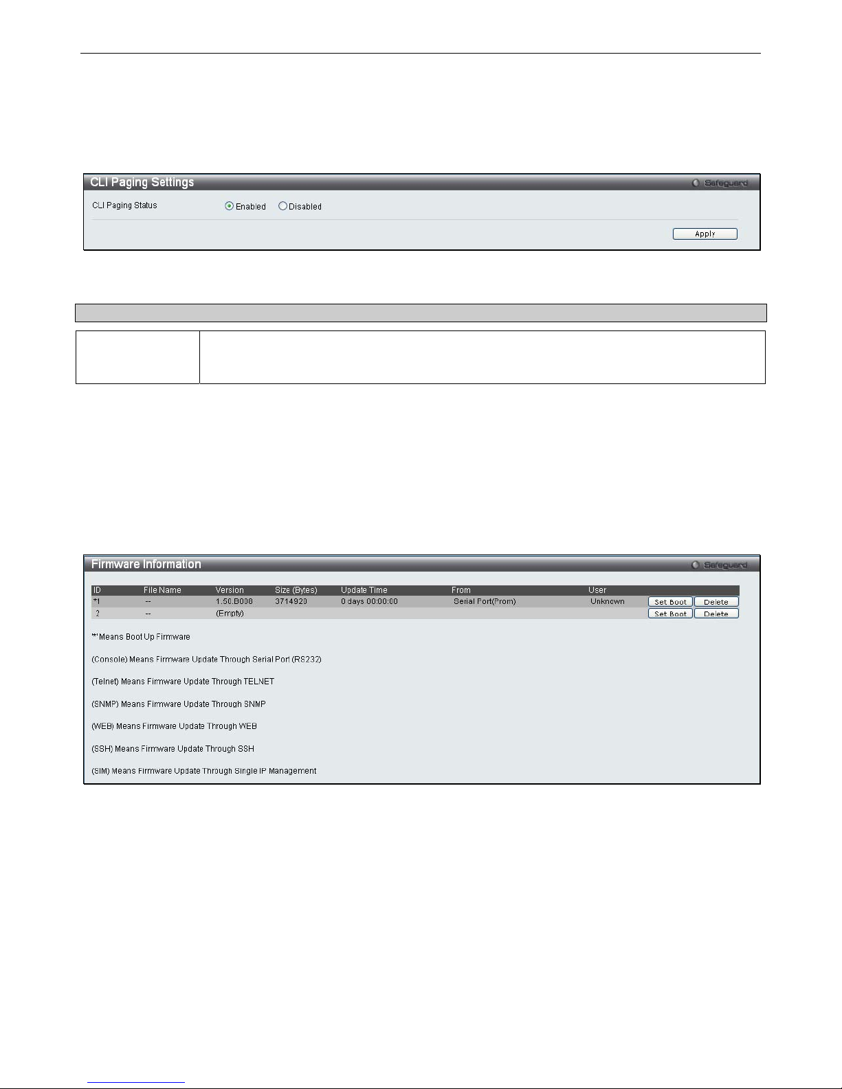
xStack® DGS-3200 Series Layer 2 Gigabit Ethernet Managed Switch
28
CLI Paging Settings
Users can stop the scrolling of multiple pages beyond the limits of the console when using the Command Line Interface.
To view the following window, click Configuration > CLI Paging Settings:
Figure 2 – 27. CLI Paging Settings window
The following parameter may be configured or viewed:
Parameter Description
CLI Paging
Status
Command Line Interface paging stops each page at the end of the console. This allows you to
stop the scrolling of multiple pages of text beyond the limits of the console. CLI Paging is
Enabled by default. To disable it, click the Disabled radio button.
Click Apply to set the CLI Paging setting.
Firmware Information
Users can view, set the next boot-up status, and delete current firmware images stored on the Switch. To set firmware as the bootup firmware the next time the Switch is restarted, click the Set Boot button. To remove the firmware from this window, click the
Delete button.
To view the following window, click Configuration > Firmware Information:
Figure 2 – 28. Firmware Information window (DGS-3200-10 and DGS-3200-16 models)
Page 42
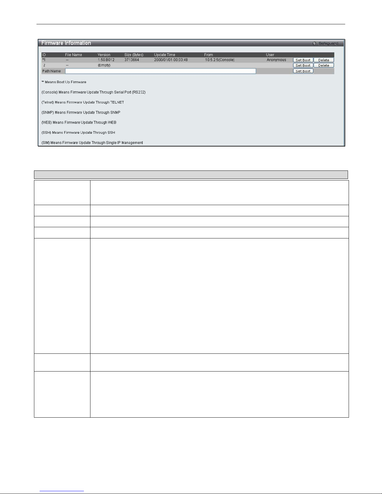
xStack® DGS-3200 Series Layer 2 Gigabit Ethernet Managed Switch
29
Figure 2 – 29. Firmware Information window (DGS-3200-24 model)
The following parameters may be configured or viewed:
Parameter Description
ID
States the image ID number of the firmware in the Switch’s memory. The Switch can store 2
firmware images for use. Image ID 1 will be the default boot-up firmware for the Switch unless
otherwise configured by the user.
Version
States the firmware version.
Size
States the size of the corresponding firmware, in bytes.
Update Time
States the specific time the firmware version was downloaded to the Switch.
From
States the IP address of the origin of the firmware. There are six ways firmware may be
downloaded to the Switch. Boot-up files are denoted by an asterisk (*) next to the file.
Console – If the IP address has the word Console next to it, it denotes a firmware upgrade
through the Console Serial Port (RS-232).
Telnet – If the IP address has the word Telnet next to it, it denotes a firmware upgrade through
Telnet.
SNMP – If the IP address has the word SNMP next to it, it denotes a firmware upgrade through
the Simple Network Management Protocol (SNMP).
WEB – If the IP address has the word WEB next to it, it denotes a firmware upgrade through the
web-based management interface.
SSH – If the IP address has the word SSH next to it, it denotes a firmware upgrade through the
Secure Shell (SSH).
SIM – If the IP address has the word SIM next to it, it denotes a firmware upgrade through the
Single IP Management feature.
User
States the user who downloaded the firmware. This field may read “Anonymous” or “Unknown”
for users that are not identified.
Path Name
(DGS-3200-24
model only)
This parameter is used to boot the Switch up from a firmware image stored on an SD card.
To boot the Switch from a firmware image stored on an SD card carry out the following:
Input the path of the firmware image on the SD-card (such as "c:\DGS3200.had").
Click the adjacent Set Boot button to use the firmware image, stored on the SD-card, as
the bootup image.
Page 43
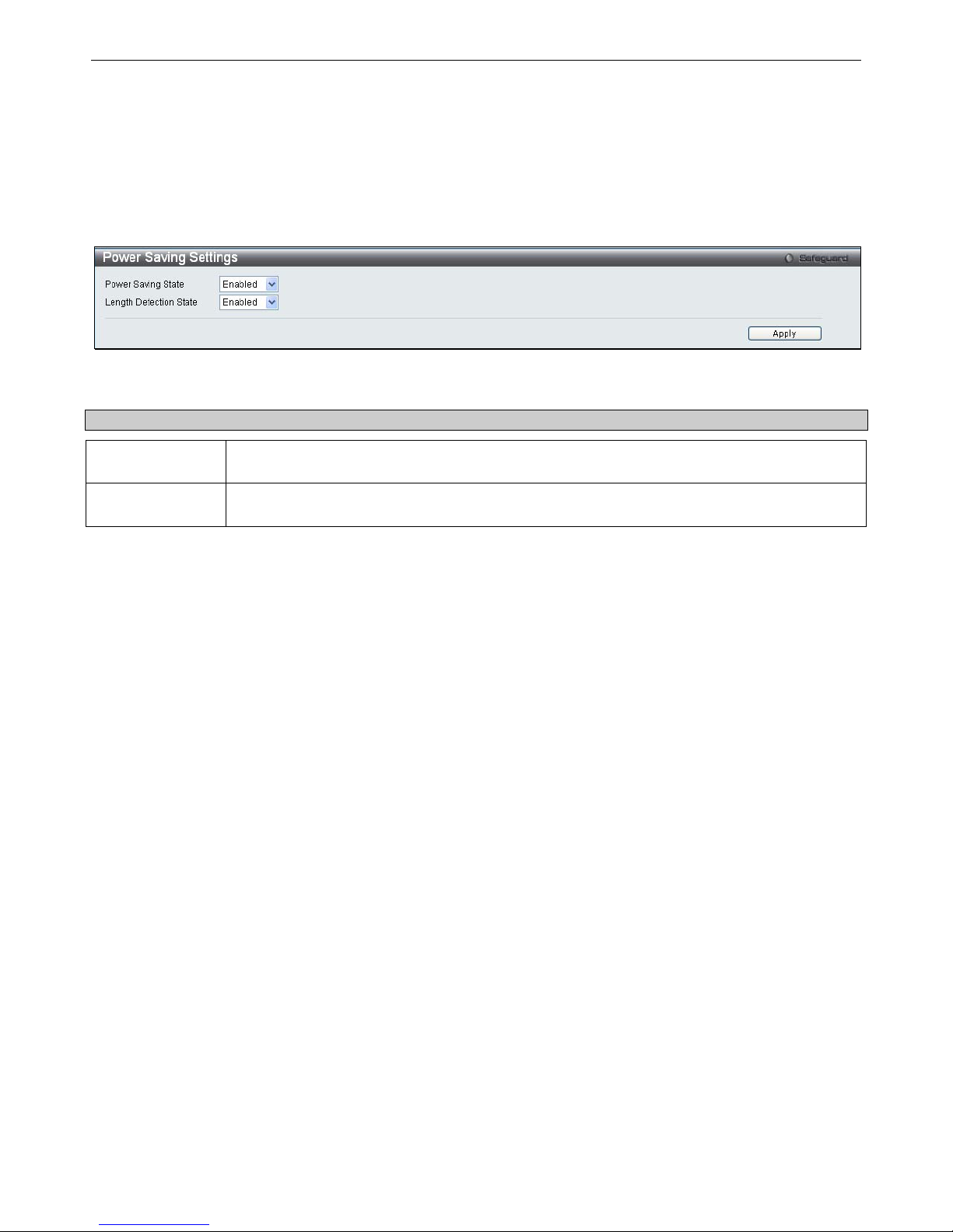
xStack® DGS-3200 Series Layer 2 Gigabit Ethernet Managed Switch
30
Power Saving Settings
This window allows the user to implement the Switch’s built-in power saving features. When the Power Saving State is Enabled,
a port which has a link down status will be turned off to save power to the Switch. This will not affect the port’s capabilities when
the port status is link up. When the Length Detection State is Enabled, the Switch will automatically determine the length of the
cable and adjust the power flow accordingly.
To view the following window, click Configuration > Power Saving Settings:
Figure 2 – 30. Power Saving Settings window
The following parameter may be configured or viewed:
Parameter Description
Power Saving
State
Power savings is Enabled by default. To disable this feature, select Disabled from the dropdown menu.
Length Detection
State
The power saving cable length detection state is Enabled by default. To disable this feature,
select Disabled from the drop-down menu.
Click Apply to set the password encryption.
Page 44
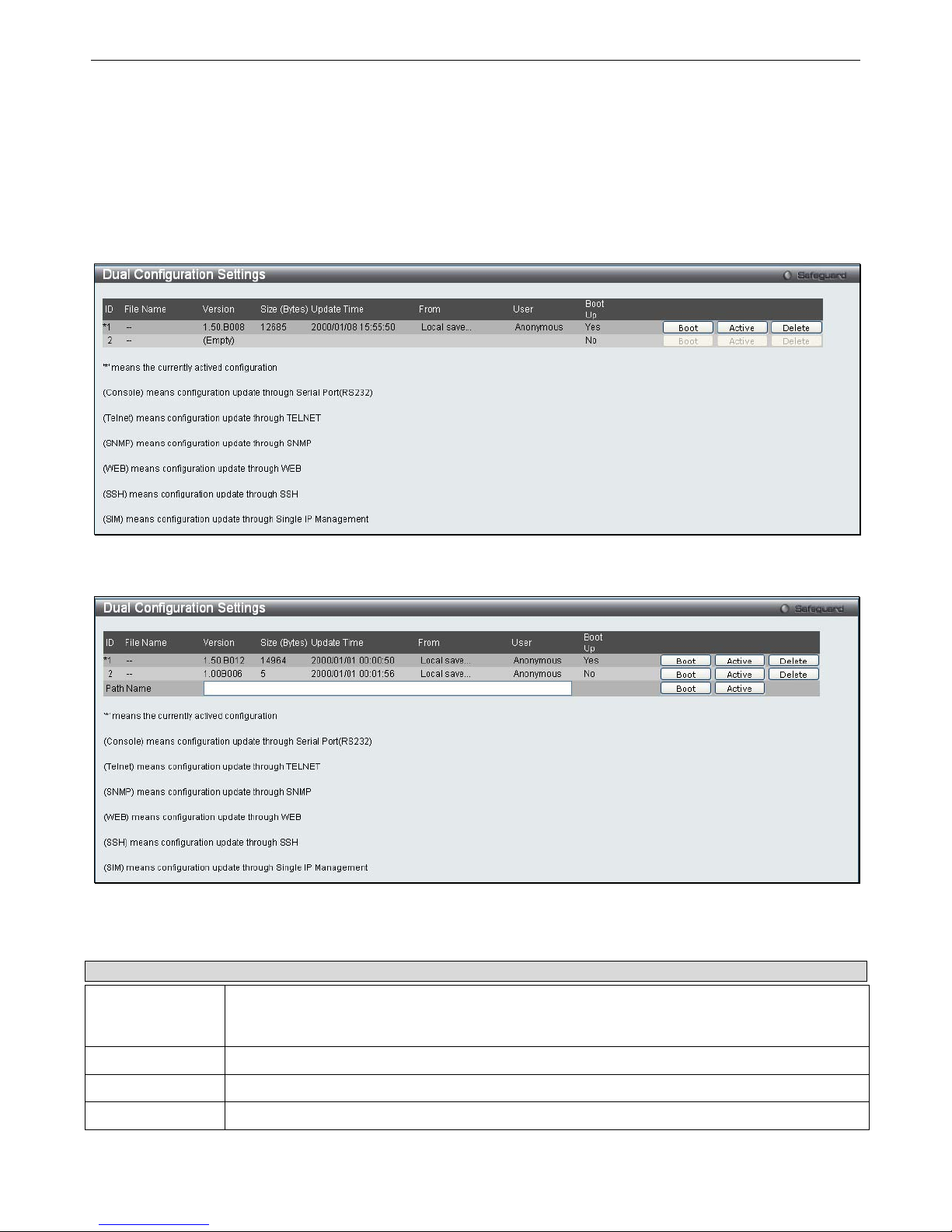
xStack® DGS-3200 Series Layer 2 Gigabit Ethernet Managed Switch
31
Dual Configuration Settings
Users can display dual configuration settings on the Switch. The Switch allows two configurations to be stored in its memory and
either can be configured as the boot-up configuration for the Switch (the DGS-3200-24 also allows configurations to be stored on
an SD-card). The user may select a boot-up configuration for the Switch by clicking the Boot button to select it. This will instruct
the Switch to use th is newly selected con figuration th e next ti me th e Switch is restarted . To d elete a co nfiguration, click t he
adjacent Delete button. To set a configuration as the active configuration, click the adjacent Active button.
To view the following window, click Configuration > Dual Configuration Settings:
Figure 2 - 31. Dual Configuration Settings window (DGS-3200-10 and DGS-3200-16 models)
Figure 2 - 32. Dual Configuration Settings window (DGS-3200-24 model)
The following parameters may be configured or viewed:
Parameter Description
ID
States the configuation ID number of the configuaration in the Switch’s memory. The Switch can
store 2 configurations for use. Configuration ID 1 will be the default boot-up configuration for the
Switch unless otherwise configured by the user.
File Name
States the file name.
Version
States the configuration version.
Size (Bytes)
States the size of the corresponding configuration, in bytes.
Page 45

xStack® DGS-3200 Series Layer 2 Gigabit Ethernet Managed Switch
32
Update Time
States the specific time the configuration version was downloaded to the Switch.
From
States the IP address of the origin of the configuration. There are five ways a configuration may
be downloaded to the Switch. Boot-up files are denoted by an asterisk (*) next to the file.
Console – If the IP address has the word Console next to it, it denotes a configuration upgrade
through the Console Serial Port (RS-232).
Telnet – If the IP address has the word Telnet next to it, it denotes a configuration upgrade
through Telnet.
SNMP – If the IP address has the word SNMP next to it, it denotes a configuration upgrade
through the Simple Network Management Protocol (SNMP).
WEB – If the IP address has the word WEB next to it, it denotes a configuration upgrade through
the web-based management interface.
SSH – If the IP address has the word SSH next to it, it denotes a configuration upgrade using
Secure Shell (SSH).
SIM – If the IP address has the word SIM next to it, it denotes a configuration upgrade through
the Single IP Management feature.
User
States the user who downloaded the configuration. This field may read “Anonymous” or
“Unknown” for users that are not identified.
Boot Up
States if the configuration will be used to boot up the Switch or not. Yes indicates that the
configuration will be used as the boot up configuration. No indicates that the configuration will not
be used as the boot up configuration.
Path Name
(DGS-3200-24
model only)
This parameter is used to boot the Switch up from a configuration stored on an SD card.
To boot the Switch from a configuration stored on an SD card carry out the following:
Input the path of configuration on the SD-card (such as "c:\DGS3200.had").
Click the adjacent Set Boot button to use the configuration, stored on the SD-card, as
the bootup configuration.
Click the adjacent Active button to make the configuration, stored on the SD-card, the
active configuration.
Setting the Boot Up Configuration:
Click the
Boot
button next to the configuration you want to use as the Boot Up configuration.
A
Success
message appears to indicate that the configuration that will be used for booting up the Switch has changed.
The Boot Up parameter next to the configuration that will be used to boot up the Switch will read Yes.
Setting the Active Configuration:
Click the
Active
button next to the configuration you want to use as the Active configuration.
A
Success
message appears to indicate that the configuration that will be used as the active configuration has changed.
An asterisk will appear next to ID of the configuration that is being used as the active configuration.
Deleting a Configuration:
Click the
Delete
button next to the configuration you want to delete.
A
Success
message appears to indicate that the configuration has been deleted.
Page 46

xStack® DGS-3200 Series Layer 2 Gigabit Ethernet Managed Switch
33
SMTP Settings
SMTP or Simple Mail Transfer Protocol is a function of the Switch that will send switch events to mail recipients based on e-mail
addresses entered in the wi ndow below. The Switch is t o be configured as a client of SMTP while the server is a remote device
that will receive messages from the Switch, place the appropriate information into an e-mail and deliver it to recipients configured
on the Switch. This can benefit the Switch administrator by simplifying the management of small workgroups or wiring closets,
increasing the speed of handling emergency Switch events, and enhancing security by recording questionable events occurring on
the Switch.
Users can set up the SMTP server for the Switch, along with setting e-mail addresses to which switch log files can be sent when a
problem arises on the Switch.
To view the following window, click Configuration > SMTP Settings:
Figure 2 - 33. SMTP Settings window
The following parameters may be configured or viewed:
Parameter Description
SMTP State
Use the radio button to enable or disable the SMTP service on this device.
SMTP Server
Address
Enter the IP address of the SMTP server on a remote device. This will be the device that sends
out the mail for you.
SMTP Server Port
(1-65535)
Enter the virtual port number that the Switch will connect with on the SMTP server. The common
port number for SMTP is 25, yet a value between 1 and 65535 can be chosen.
Self Mail Address
Enter the e-mail address from which mail messages will be sent. This address will be the “from”
address on the e-mail message sent to a recipient. Only one self-mail address can be configured
for this Switch. This string can be no more that 64 alphanumeric characters.
Add A Mail
Receiver
Enter an e-mail address and click the Add button. Up to eight e-mail addresses can be added
per Switch. To delete these addresses from the Switch, click the corresponding Delete button in
the SMTP Mail Receiver Address table at the bottom of the window.
Page 47
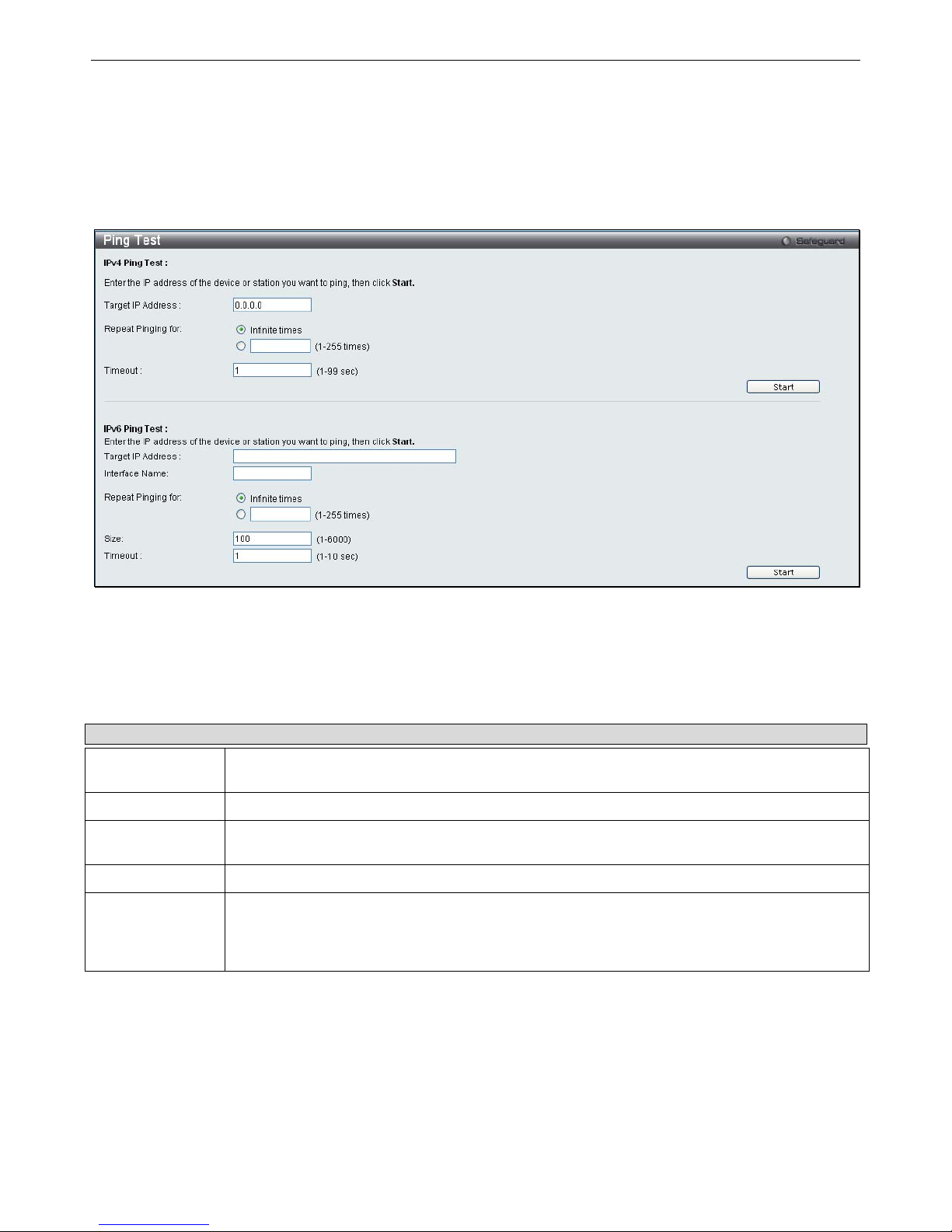
xStack® DGS-3200 Series Layer 2 Gigabit Ethernet Managed Switch
34
Ping Test
Users can Ping either an IPv4 address or an IPv6 address. Ping is a small program that sends ICMP Echo packets to the IP address
you specify. The destination node t hen responds to or “echoes” t he packets sent from the Switch. Thi s is very useful t o verify
connectivity between the Switch and other nodes on the network.
To view the following window, click Configuration > Ping Test:
Figure 2 - 34. Ping Test window
The user m ay click th e Infinite ti mes rad io button, in t he Rep eat Pi nging fo r field, which will tell th e ping program to k eep
sending ICMP Echo pac kets to the s pecified IP addre ss until the program is stoppe d. The user m ay opt to c hoose a specific
number of times to ping the Target IP Address by clicking its radio button and entering a number between 1 and 255. Click Start
to initiate the Ping program.
The following parameters may be configured or viewed:
Parameter Description
Target IP
Address
Enter an IP address to be Pinged.
Interface Name
For IPv6 only, enter the name of the interface to be Pinged.
Repeat Pinging
for
Enter the number of times desired to attempt to Ping either the IPv4 address or the IPv6 address
configured in this window. Users may enter a number of times between 1 and 255.
Size
For IPv6 only, enter a value between 1 and 6000. The default is 100.
Timeout
For IPv4, select a timeout period between 1 and 99 seconds for this Ping message to reach its
destination. For IPv6, select a timeout period between 1 and 10 seconds for this Ping message
to reach its destination. In either case, if the packet fails to find the IP address in this specified
time, the Ping packet will be dropped.
Click Start to initialize the Ping program.
Page 48
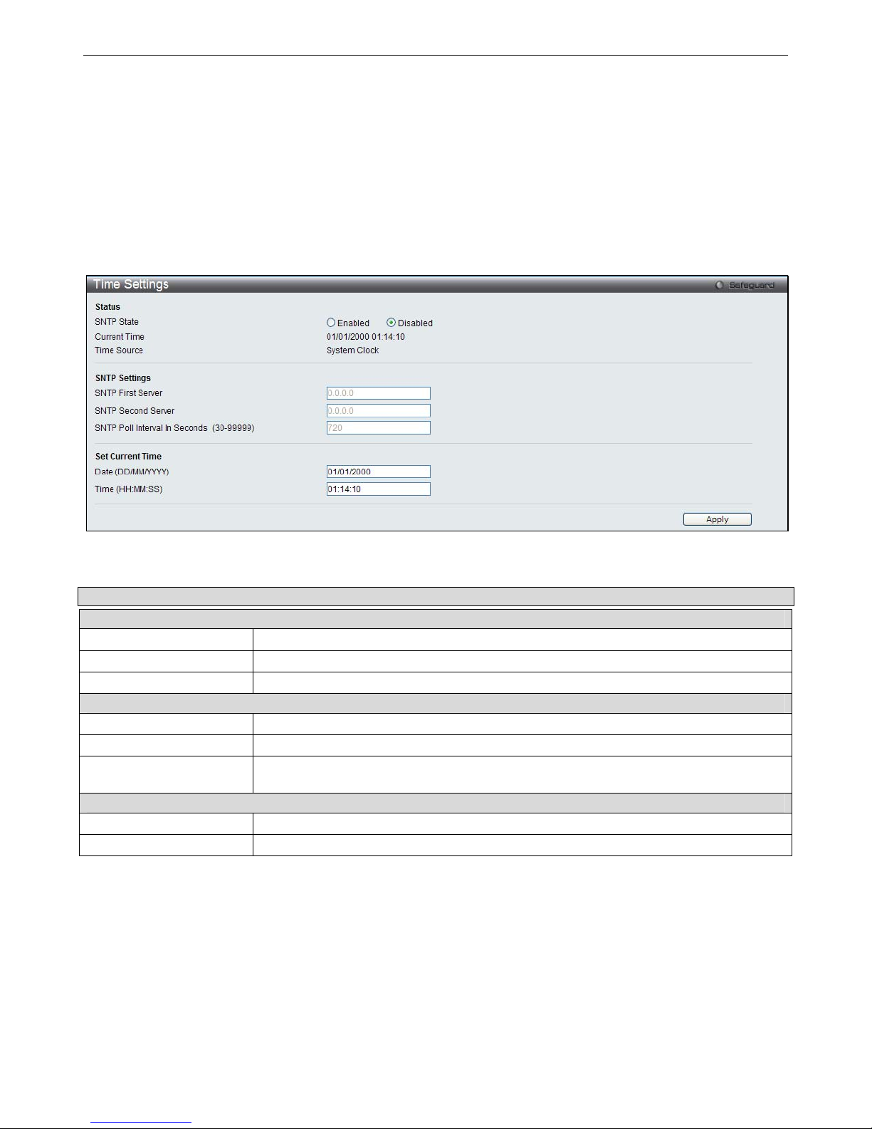
xStack® DGS-3200 Series Layer 2 Gigabit Ethernet Managed Switch
35
SNTP Settings
SNTP or Simple Network Time Protocol is used by the Switch to synchronize the clock of the computer.
The SNTP Settings folder contains two windows: Time Settings and TimeZone Settings.
Time Settings
Users can configure the time settings for the Switch.
To view the following window, click Configuration > SNTP Settings > Time Settings:
Figure 2 - 35. Time Settings window
The following parameters can be set or are displayed:
Parameter Description
Status
SNTP State
Use this radio button to enable or disable SNTP.
Current Time
Displays the Current Time.
Time Source
Displays the time source for the system.
SNTP Settings
SNTP First Server
The IP address of the primary server from which the SNTP information will be taken.
SNTP Second Server
The IP address of the secondary server from which the SNTP information will be taken.
SNTP Poll Interval In
Seconds (30-99999)
The interval, in seconds, between requests for updated SNTP information.
Set Current Time
Date (DD/MM/YYYY)
Enter the current day, month, and year to update the system clock.
Time (HH:MM:SS)
Enter the current time in hours, minutes, and seconds.
Click Apply to implement your changes.
Page 49
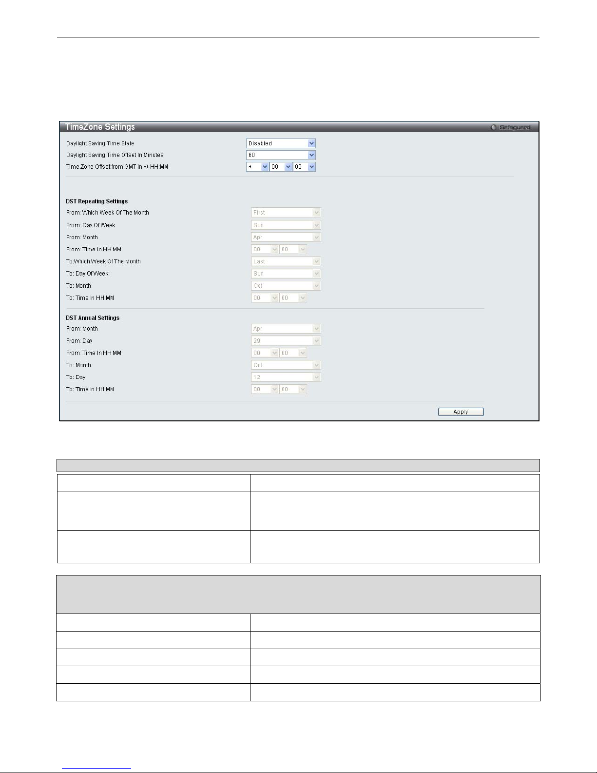
xStack® DGS-3200 Series Layer 2 Gigabit Ethernet Managed Switch
36
Time Zone Settings
Users can configure time zones and Daylight Savings Time settings for SNTP.
To view the following window, click Configuration > SNTP Settings > Time Zone Settings:
Figure 2 - 36. Time Zone Settings window
The following parameters can be set:
Parameter Description
Daylight Saving Time State
Use this drop-down menu to enable or disable the DST Settings.
Daylight Saving Time Offset In Minutes
Use this drop-down menu to specify the amount of time that will
constitute your local DST offset. The available options are 30, 60,
90, or 120 minutes.
Time Zone Offset From GMT In +/- HH:MM
Use these drop-down menus to specify your local time zone’s offset
from Greenwich Mean Time (GMT.)
DST Repeating Settings – Using repeating mode will enable DST seasonal time adjustment. Repeating mode
requires that the DST beginning and ending date be specified using a formula. For example, specify to begin DST on
Saturday during the second week of April and end DST on Sunday during the last week of October.
From: Which Week Of The Month
Enter the week of the month that DST will start.
From: Day Of Week
Enter the day of the week that DST will start on.
From: Month
Enter the month DST will start on.
From: Time In HH:MM
Enter the time of day that DST will start on.
To: Which Week Of The Month
Enter the week of the month the DST will end.
Page 50
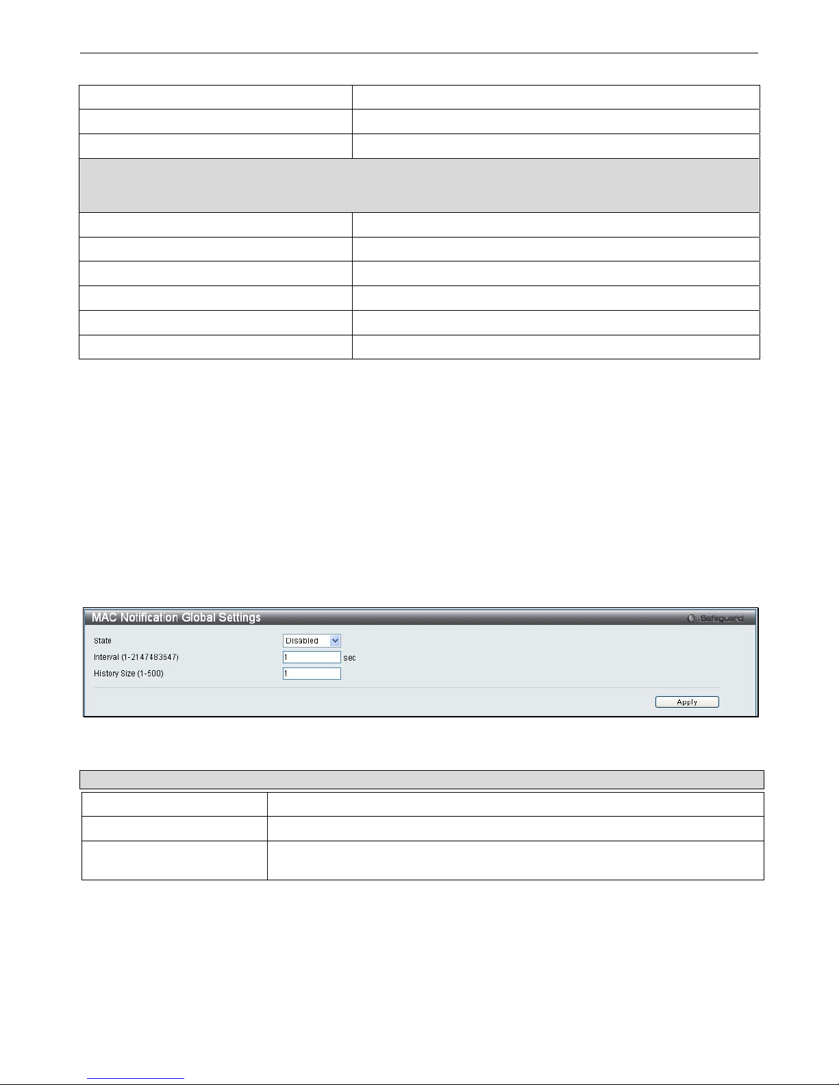
xStack® DGS-3200 Series Layer 2 Gigabit Ethernet Managed Switch
37
To: Day Of Week
Enter the day of the week that DST will end.
To: Month
Enter the month that DST will end.
To: Time In HH:MM
Enter the time DST will end.
DST Annual Settings – Using annual mode will enable DST seasonal time adjustment. Annual mode requires that
the DST beginning and ending date be specified concisely. For example, specify to begin DST on April 3 and end
DST on October 14.
From: Month
Enter the month DST will start on, each year.
From: Day
Enter the day of the month DST will start on, each year.
From: Time In HH:MM
Enter the time of day DST will start on, each year.
To: Month
Enter the month DST will end on, each year.
To: Day
Enter the day of the month DST will end on, each year.
To: Time In HH:MM
Enter the time of day that DST will end on, each year.
Click Apply to implement changes made to this window.
MAC Notification Settings
MAC Notification is used to monitor MAC addresses learned and entered into the forwarding database.
The MAC Notification Settings folder contains two windows: MAC Notification Global Settings and MAC Notification Port
Settings.
MAC Notification Global Settings
This window allows you to globally set MAC notification on the Switch.
To view the following window, click Configuration > MAC Notification Settings > MAC Notification Global Settings:
Figure 2 - 37. MAC Notification Global Settings window
The following parameters may be viewed and modified:
Parameter Description
State
Enable or disable MAC notification globally on the Switch
Interval (1-2147483647)
The time in seconds between notifications.
History Size (1-500)
The maximum number of entries listed in the history log used for notification. Up to
500 entries can be specified.
Click Apply to implement your changes.
Page 51
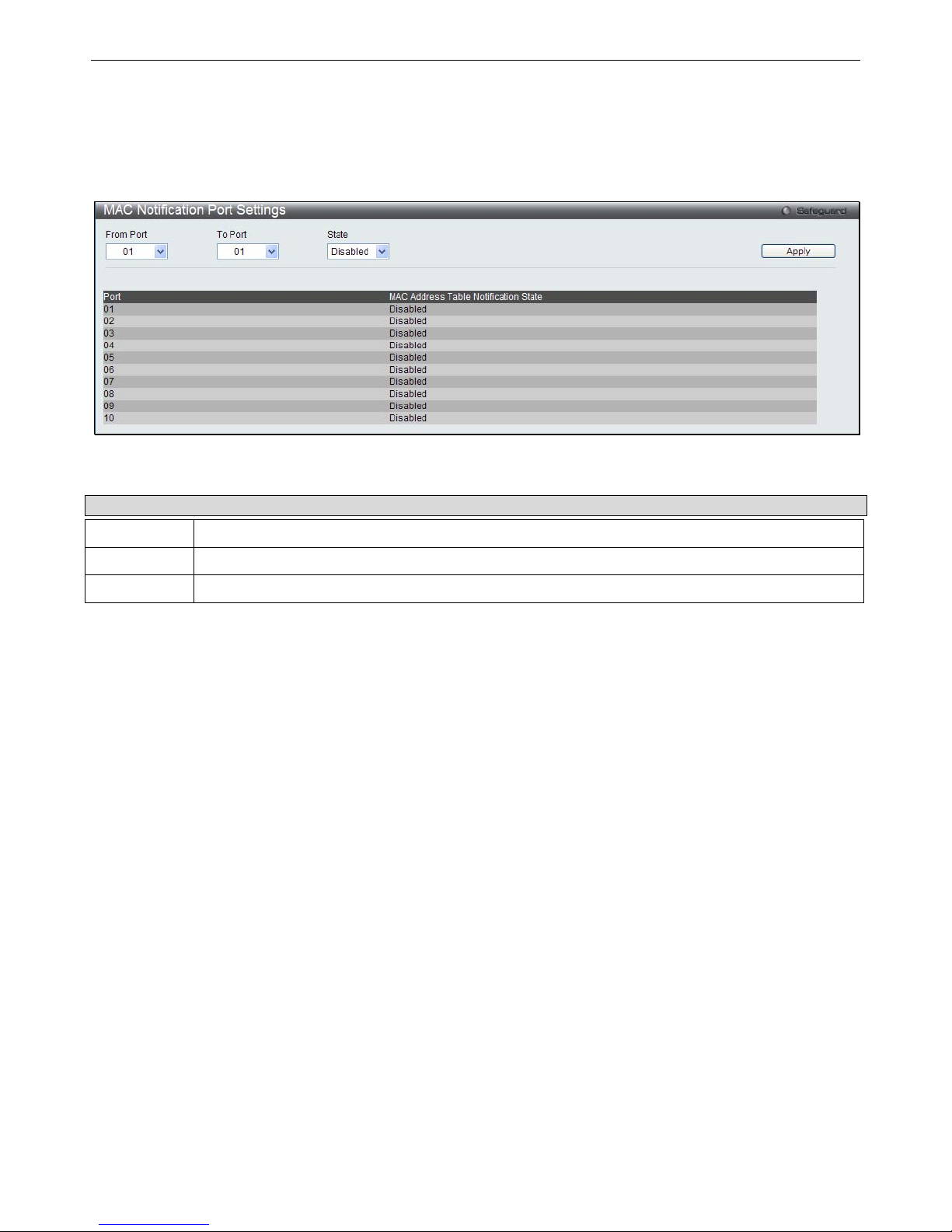
xStack® DGS-3200 Series Layer 2 Gigabit Ethernet Managed Switch
38
MAC Notification Port Settings
Users can set MAC notification for individual ports on the Switch.
To view the following window, click Configuration > MAC Notification Settings > MAC Notification Port Settings:
Figure 2 - 38. MAC Notification Port Settings window
To change MAC notification settings for a port or group of ports on the Switch, configure the following parameters.
Parameter Description
From Port
Select a beginning port to enable for MAC notification using the drop-down menu.
To Port
Select an ending port to enable for MAC notification using the drop-down menu.
State
Enable MAC Notification for the ports selected using the drop-down menu.
Click Apply to implement changes made.
Page 52

xStack® DGS-3200 Series Layer 2 Gigabit Ethernet Managed Switch
39
SNMP Settings
Simple Network Management Protocol (SNMP) is an OS I Layer 7 (Application Layer) designed specifically for managing and
monitoring network de vices. SNMP enables network management stations to read and modify the settings of gateways, routers,
switches, a nd other net work devices. Use SNMP t o co nfigure sy stem f eatures for proper operation, monitor pe rformance an d
detect potential problems in the Switch, switch group or network.
Managed devices that support SNMP include software (referred to as an agent), which runs locally on the device. A defined set of
variables (m anaged objects) i s maintained b y the SNMP a gent and used to m anage t he de vice. These o bjects are defined i n a
Management I nformation B ase (M IB), which provides a standard presentation o f t he information c ontrolled by t he o n-board
SNMP agent. SNMP defines both the format of t he MIB specifications and the protocol used to access this information over the
network.
The Switch supports the SNMP versions 1, 2c, and 3. The three versions of SNMP vary in the level of security provided between
the management station and the network device.
In SNMP v.1 and v.2, user a uthentication is accomplished using ‘community strings’, which function like passwords. The remote
user SNMP application and the Switch SNMP must use the same community string. SNMP packets from any station that has not
been authenticated are ignored (dropped).
The default community strings for the Switch used for SNMP v.1 and v.2 management access are:
public – Allows authorized management stations to retrieve MIB objects.
private – Allows authorized management stations to retrieve and modify MIB objects.
SNMPv3 uses a more sophisticated authentication process that is sep arated into two parts. The first p art is to maintain a list of
users and their attributes that are allowed to act as SNMP managers. The second part describes what each user on that list can do
as an SNMP manager.
The Switch allows groups of users to be listed and configured with a shared set of privileges. The SNMP version may also be set
for a l isted group of S NMP m anagers. T hus, y ou m ay creat e a group of S NMP m anagers t hat a re allowed t o vi ew read-only
information or receive traps using SNMPv1 while assigning a higher level of secu rity to another group, granting read/write privileges using SNMPv3.
Using S NMPv3 i ndividual users or g roups of S NMP m anagers ca n be al lowed t o p erform or be restricted f rom pe rforming
specific SNM P m anagement fun ctions. Th e fun ctions allowed or re stricted are defined usin g th e Obj ect Id entifier (OID)
associated wit h a s pecific MIB. An a dditional layer of secu rity is av ailable for SNMPv3 in th at SNMP m essages m ay b e
encrypted. To read more about how to configure SNMPv3 settings for the Switch read the next section.
Traps
Traps are m essages that alert network personnel of eve nts that occur on the Switch. The eve nts can be as se rious as a reboot
(someone acci dentally turned OFF the Switch), or less serious like a port status ch ange. The Switch generates traps and se nds
them to the trap recipient (or network manager). Typical traps include trap messages for Authentication Failure, Topology Change
and Broadcast\Multicast Storm.
MIBs
The S witch i n t he M anagement In formation B ase (MIB) st ores m anagement and counter i nformation. The Switch u ses t he
standard MIB-II Management Information Base module. Consequently, values for MIB objects can be retrieved from any SNMPbased network management software. In addition to the standard MIB-II, the Switch also supports its own proprietary enterprise
MIB as an extended Management Information Base. Specifying the MIB Object Identifier may also retrieve the proprietary MIB.
MIB values can be either read-only or read-write.
The Switch incorporates a flexible SNMP management for the switching environment. SNMP management can be customized to
suit the needs of the networks and the preferences of the network administrator. Use the SNMP V3 menus to select th e SNMP
version used for specific tasks.
The Switch supports the Simple Network Management Protocol (SNMP) versions 1, 2c, and 3. The administrator can specify the
SNMP version use d t o m onitor a nd c ontrol t he S witch. The t hree ve rsions o f S NMP va ry i n t he level o f sec urity pro vided
between the management station and the network device.
SNMP settings are configured using the menus located on the SNMP V3 folder of the Web manager. Workstations on the network
that are allowed SNMP privileged access to the Switch can be restricted with the Management Station IP Address menu.
Page 53
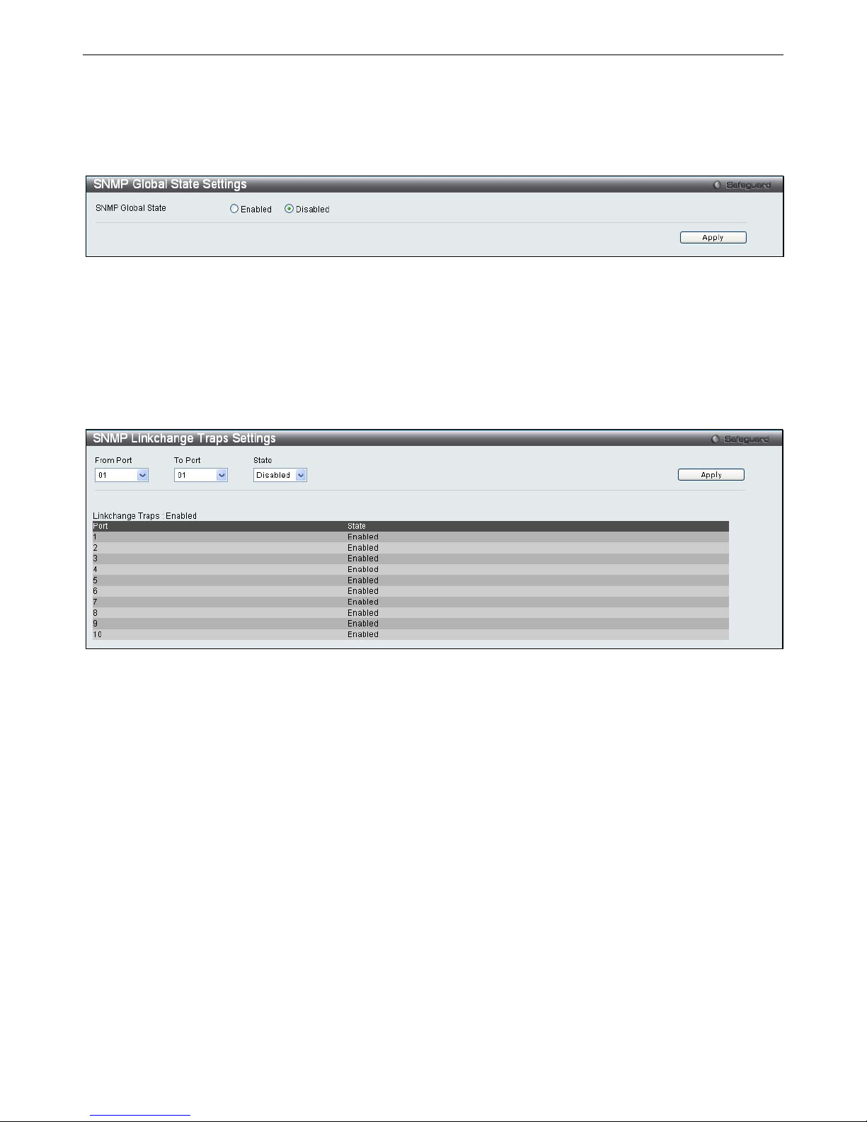
xStack® DGS-3200 Series Layer 2 Gigabit Ethernet Managed Switch
40
SNMP Global State Settings
SNMP global state settings can be enabled or disabled.
To view the following window, click Configuration > SNMP Settings > SNMP Global State Settings:
Figure 2 - 39. SNMP Global State Settings window
Click the
Apply
button to let your change take effect.
SNMP Linkchange Trap Settings
Users can set SNMP linkchange traps.
To view the following window, click Configuration > SNMP Settings > SNMP Linkchange Trap Settings:
Figure 2 - 40. SNMP Linkchange Trap Settings window
To set SNMP linkchange traps on the Switch, use the From Port and To Port drop-down menus to select the desired port range and
then change the State to Enabled.
Page 54
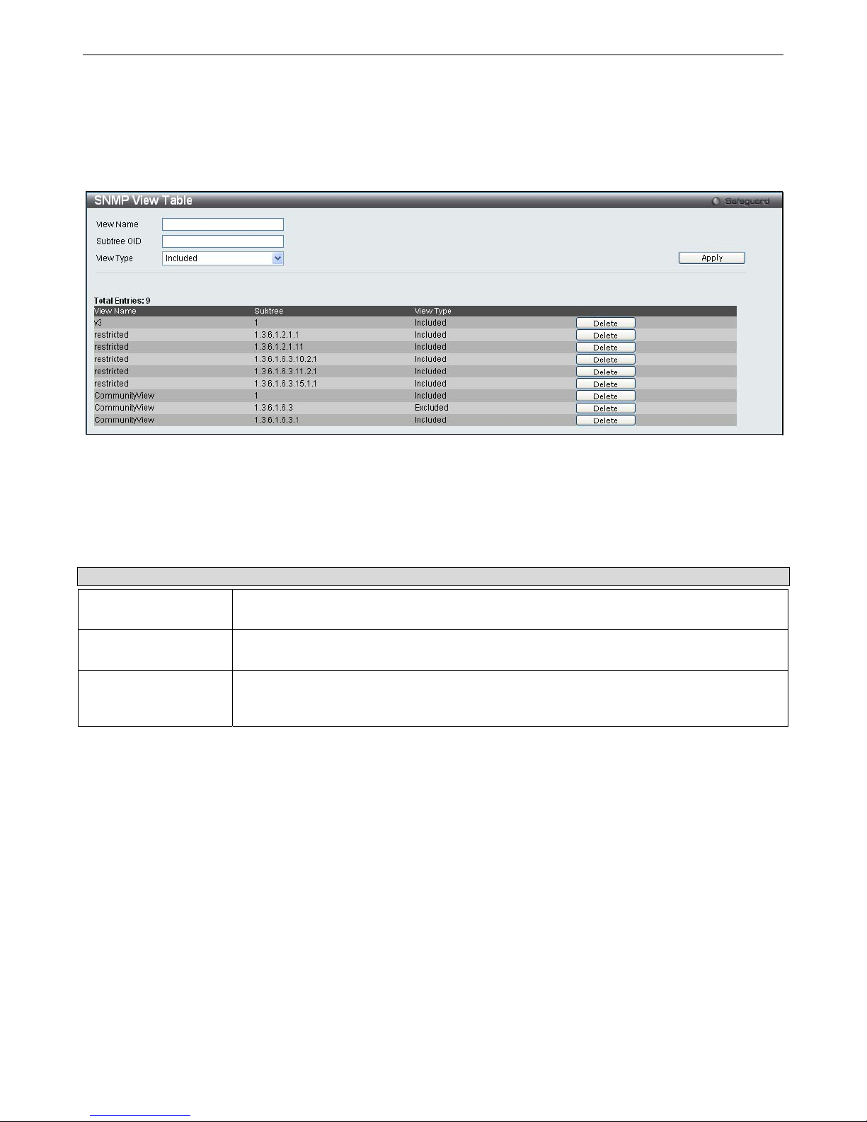
xStack® DGS-3200 Series Layer 2 Gigabit Ethernet Managed Switch
41
SNMP View Table
Users can assign views to community strings that define which MIB objects can be accessed by a remote SNMP manager.
To view the following window, click Configuration > SNMP Settings > SNMP View Table:
Figure 2 - 41. SNMP View Table window
To delete an existing SNMP View Table entry, click the Delete button corresponding to the entry to delete. To create a new entry,
enter the information above the table and then click the Apply button.
The SNMP Gro up created with th is tab le maps SNMP users (id entified in the SNMP User Ta ble) to t he vie ws created i n t he
previous window.
The following parameters can set:
Parameter Description
View Name
Type an alphanumeric string of up to 32 characters. This is used to identify the new SNMP
view being created.
Subtree OID
Type the Object Identifier (OID) Subtree for the view. The OID identifies an object tree (MIB
tree) that will be included or excluded from access by an SNMP manager.
View Type
Select Included to include this object in the list of objects that an SNMP manager can
access. Select Excluded to exclude this object from the list of objects that an SNMP
manager can access.
To implement your new settings, click Apply.
Page 55
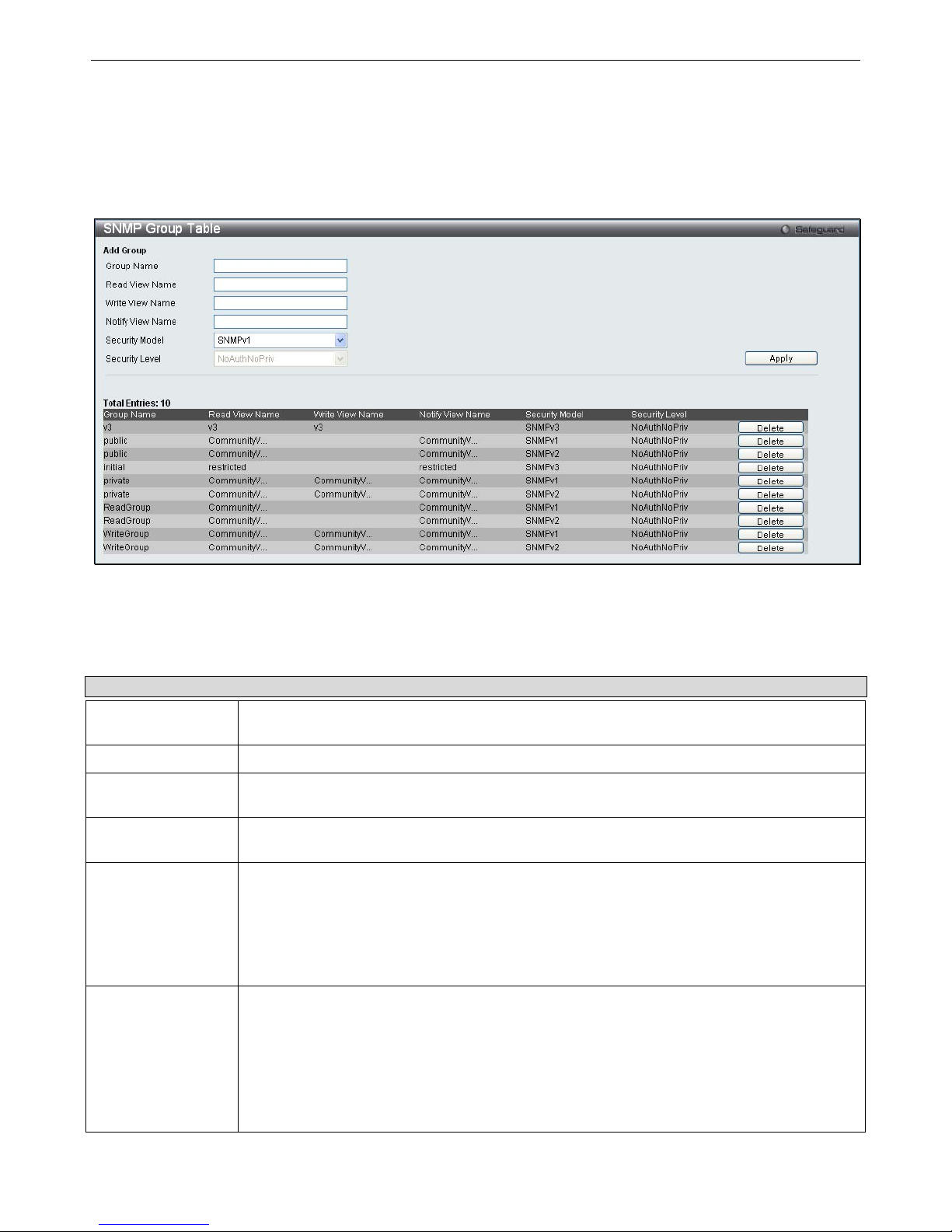
xStack® DGS-3200 Series Layer 2 Gigabit Ethernet Managed Switch
42
SNMP Group Table
An SNMP G roup c reated with t his t able maps SNM P u sers (i dentified in th e SNMP User Tab le) t o the views created in the
previous window.
To view the following window, click Configuration > SNMP Settings > SNMP Group Table:
Figure 2 - 42. SNMP Group Table window
To delete an existing SNMP Group Table entry, click the Delete button next to the corresponding entry.
To add a new entry to the Switch’s SNMP Group Table, enter the information at the top of the window and then click Apply.
The following parameters can set:
Parameter Description
Group Name
Type an alphanumeric string of up to 32 characters. This is used to identify the new SNMP
group of SNMP users.
Read View Name
This name is used to specify the SNMP group created can request SNMP messages.
Write View Name
Specify an SNMP group name for users that are allowed SNMP write privileges to the Switch’s
SNMP agent.
Notify View Name
Specify a SNMP group name for users that can receive SNMP trap messages generated by
the Switch’s SNMP agent.
Security Model
SNMPv1 – Specifies that SNMP version 1 will be used.
SNMPv2 – Specifies that SNMP version 2c will be used. The SNMPv2 supports both
centralized and distributed network management strategies. It includes improvements in the
Structure of Management Information (SMI) and adds some security features.
SNMPv3 – Specifies that the SNMP version 3 will be used. SNMPv3 provides secure access
to devices through a combination of authentication and encrypting packets over the network.
Security Level
The Security Level settings only apply to SNMPv3.
NoAuthNoPriv – Specifies that there will be no authorization and no encryption of packets sent
between the Switch and a remote SNMP manager.
AuthNoPriv – Specifies that authorization will be required, but there will be no encryption of
packets sent between the Switch and a remote SNMP manager.
AuthPriv – Specifies that authorization will be required, and that packets sent between the
Switch and a remote SNMP manger will be encrypted.
Page 56
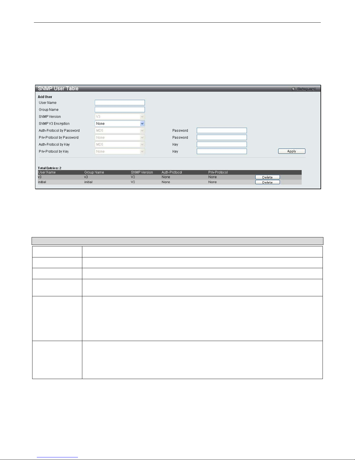
xStack® DGS-3200 Series Layer 2 Gigabit Ethernet Managed Switch
43
To implement your new settings, click Apply.
SNMP User Table
This window displays all of the SNMP User’s currently configured on the Switch.
To view the following window, click Configuration > SNMP User Table:
Figure 2 - 43. SNMP User Table window
To delete an existing SNMP User Table entry, click the Delete button corresponding to the entry to delete.
To display the detailed entry for a given user, click on the View button. This will open the SNMP User Table Display window,
as shown below.
The following parameters are displayed:
Parameter Description
User Name
An alphanumeric string of up to 32 characters. This is used to identify the SNMP users.
Group Name
This name is used to specify the SNMP group created can request SNMP messages.
SNMP Version
V3 – Indicates that SNMP version 3 is in use.
SNMP V3
Encryption
Use the drop-down menu to enable encryption for SNMP V3. This is only operable in SNMP V3
mode. The choices are None, Password, or Key.
Auth-Protocol MD5 – Specifies that the HMAC-MD5-96 authentication level will be used. This field is only
operable when V3 is selected in the SNMP Version field and the Encryption field has been
checked. This field will require the user to enter a password.
SHA – Specifies that the HMAC-SHA authentication protocol will be used. This field is only
operable when V3 is selected in the SNMP Version field and the Encryption field has been
checked. This field will require the user to enter a password.
Priv-Protocol
None – Specifies that no authorization protocol is in use.
DES – Specifies that DES 56-bit encryption is in use, based on the CBC-DES (DES-56)
standard. This field is only operable when V3 is selected in the SNMP Version field and the
Encryption field has been checked. This field will require the user to enter a password between 8
and 16 alphanumeric characters.
To implement changes made, click Apply.
Page 57

xStack® DGS-3200 Series Layer 2 Gigabit Ethernet Managed Switch
44
SNMP Community Table
Users can create an SNMP community string to define the relationship between the SNMP manager and an agent. The community
string acts like a password to permit access to the a gent on the Switch. One or m ore of the fo llowing c haracteristics can be
associated with the community string:
An Access List of IP addresses of SNMP managers that are permitted to use the c ommunity string to gain access to the
Switch’s SNMP agent.
Any MIB view that defines the subset of all MIB objects will be accessible to the SNMP community.
Read/write or read-only level permission for the MIB objects accessible to the SNMP community.
To view the following window, click SNMP Settings > Configuration > SNMP Community Table:
Figure 2 - 44. SNMP Community Table window
The following parameters can set:
Parameter Description
Community Name
Type an alphanumeric string of up to 32 characters that is used to identify members of an
SNMP community. This string is used like a password to give remote SNMP managers access
to MIB objects in the Switch’s SNMP agent.
View Name
Type an alphanumeric string of up to 32 characters that is used to identify the group of MIB
objects that a remote SNMP manager is allowed to access on the Switch. The view name must
exist in the SNMP View Table.
Access Right
Read Only – Specifies that SNMP community members using the community string created
can only read the contents of the MIBs on the Switch.
Read Write – Specifies that SNMP community members using the community string created
can read from, and write to the contents of the MIBs on the Switch.
To im plement th e n ew setti ngs, click Apply. To d elete an en try from th e SN MP Co mmunity T able, click th e Delete b utton
corresponding to the entry to delete.
Page 58
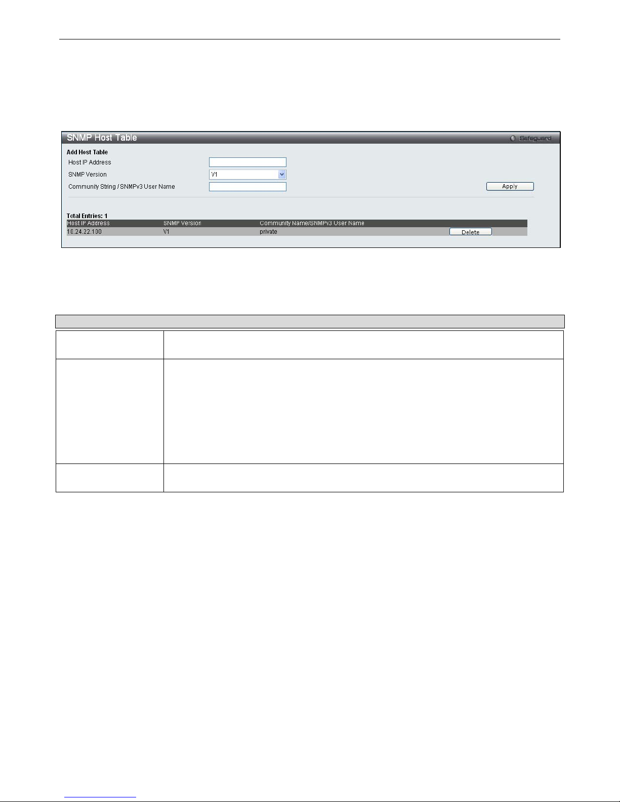
xStack® DGS-3200 Series Layer 2 Gigabit Ethernet Managed Switch
45
SNMP Host Table
Users can set up SNMP trap recipients for IPv4.
To view the following window, click Configuration > SNMP Settings > SNMP Host Table:
Figure 2 - 45. SNMP Host Table window
To add a new entry to the Switch’s SNMP Ho st Table, enter the information at the top of the window and then click the Apply
button. To delete an existing SNMP Host Table entry, click the Delete button corresponding to the entry to delete.
The following parameters can set:
Parameter Description
Host IP Address
Type the IP address of the remote management station that will serve as the SNMP host for
the Switch.
SNMP Version
V1 – To specify that SNMP version 1 will be used.
V2c – To specify that SNMP version 2c will be used.
V3-NoAuthNoPriv – To specify that the SNMP version 3 will be used, with a NoAuth-NoPriv
security level.
V3-AuthNoPriv – To specify that the SNMP version 3 will be used, with an Auth-NoPriv
security level.
V3-AuthPriv – To specify that the SNMP version 3 will be used, with an Auth-Priv security
level.
Community String /
SNMP V3 User Name
Type in the community string or SNMP V3 user name as appropriate.
To implement your new settings, click Apply.
Page 59

xStack® DGS-3200 Series Layer 2 Gigabit Ethernet Managed Switch
46
SNMP v6Host Table
Users can set up SNMP trap recipients for IPv6.
To view the following window, click Configuration > SNMP Settings > SNMP v6Host Table:
Figure 2 - 46. SNMP v6Host Table window
To add a new entry to the Switch’s SNMP v6Host Table, enter the information at the top of the window and then click the Apply
button. To delete an existing SNMP v6Host Table entry, click the Delete button corresponding to the entry to delete.
The following parameters can set:
Parameter Description
Host IPv6 Address
Type the IP address of the remote management station that will serve as the SNMP host for
the Switch.
SNMP Version
V1 – To specify that SNMP version 1 will be used.
V2c – To specify that SNMP version 2c will be used.
V3-NoAuthNoPriv – To specify that the SNMP version 3 will be used, with a NoAuth-NoPriv
security level.
V3-AuthNoPriv – To specify that the SNMP version 3 will be used, with an Auth-NoPriv
security level.
V3-AuthPriv – To specify that the SNMP version 3 will be used, with an Auth-Priv security
level.
Community String /
SNMP V3 User Name
Type in the community string or SNMP V3 user name as appropriate.
To implement your new settings, click Apply.
Page 60

xStack® DGS-3200 Series Layer 2 Gigabit Ethernet Managed Switch
47
SNMP Engine ID
The Engine ID is a unique identifier used for SNMP V3 implementations on the Switch.
To view the following window, click Configuration > SNMP Settings > SNMP Engine ID:
Figure 2 - 47. SNMP Engine ID window
To change the Engine ID, type the new Engine ID value in the space provided.
The following parameter can be set:
Parameter Description
Engine ID
The SNMP engine ID displays the identification of the SNMP engine on the Switch. The
default value is suggested in RFC2271. The very first bit is 1, and the first four octets are set
to the binary equivalent of the agent’s SNMP management private enterprise number as
assigned by IANA (D-Link is 171). The fifth octet is 03 to indicate the rest is the MAC
address of this device. The sixth to eleventh octets is the MAC address.
To implement your new settings, click Apply.
SNMP Trap Configuration
Users can enable and d isable global SNMP trap support, SNMP authentication failure trap support, Linkchange Traps, Coldstart
Traps, and Warmstart Traps. To enable Linkchange Traps for a specific port or range of ports, go to the SNMP Linkchange Trap
Settings window (Configuration > SNMP Settings > SNMP Linkchange Trap Settings).
To view the following window, click Configuration > SNMP Settings > SNMP Trap Configuration:
Figure 2 - 48. SNMP Trap Configuration window
To enable or disable the SNMP Traps, SNMP Authenticate Traps, Linkchange Traps, Coldstart Traps, and Warmstart Traps, use
the corresponding drop-down menu to change and click Apply.
Page 61

xStack® DGS-3200 Series Layer 2 Gigabit Ethernet Managed Switch
48
RMON
Users can enable and disable remote monitoring (RMON) status for the SNMP function on the Switch. In addition, RMON Rising
and Falling Alarm Traps can be enabled and disabled.
To view the following window, click Configuration > SNMP Settings > RMON:
Figure 2 - 49. RMON window
To enable or disable RMON for SNMP, use the radio buttons. Click Apply when finished.
CPU Filter L3 Control Packet Settings
Users can discard and display Layer 3 control packets sent to the CPU from specific ports.
To view the following window, click Configuration > CPU Filter L3 Control Packet Settings:
Figure 2 - 50. CPU Filter L3 Control Packet Settings window
To set CPU filter Layer 3 control packet settings on the Switch, use the From Port and To Port drop-down menus to select the
desired port range, change the State to Enabled, and tick the desired Layer 3 categories (IGMP Query, DVMRP, PIM, OSPF, RIP,
VRRP, or All). Click
Apply
when finished.
Single IP Management
Simply put, D-Link Single IP Management is a co ncept that will stack switches together over Ethernet instead of using stacking
ports or modules. There are some advantages in implementing the “Single IP Management” feature:
1. SIM can si mplify management o f sm all w orkgroups or wiring cl osets whi le scal ing t he net work t o han dle i ncreased
bandwidth demand.
2. SIM can reduce the number of IP address needed in your network.
3. SIM can eliminate any specialized cables for stacking connectivity and remove the distance barriers that typically limit
your topology options when using other stacking technology.
Switches using D-Link Single IP Management (labeled here as SIM) must conform to the following rules:
SIM is a n optional feature on the Switch a nd can easily be enabled or disabled through the Command Line Interface or
Web Interface. SIM grouping has no effect on the normal operation of the Switch in the user’s network.
Page 62

xStack® DGS-3200 Series Layer 2 Gigabit Ethernet Managed Switch
49
There are three classifications for switches using SIM. The Commander Switch (CS), which is the master switch of the
group, Member Switch (MS), which is a sw itch t hat i s r ecognized by the CS a member of a SIM group, an d a
Candidate Switch (CaS), which is a Switch that has a physical link to the SIM group but has not been recognized by the
CS as a member of the SIM group.
A SIM group can only have one Commander Switch (CS).
All swi tches i n a pa rticular SIM group must be i n the same IP s ubnet (broadcast domain). M embers of a SIM group
cannot cross a router.
A SIM group accepts up to 32 switches (numbered 1-32), not including the Commander Switch (numbered 0).
There is no limit to the number of SIM groups in th e same IP subnet (broadcast domain); however a si ngle switch can
only belong to one group.
If multiple VLANs are configured, the SIM group will only utilize the default VLAN on any switch.
SIM all ows intermediate devices that do not support SIM. This enables the user to m anage switches that are m ore than
one hop away from the CS.
The SIM group is a group of switches that are managed as a single entity. The Switch may take on three different roles:
1. Commander Switch (CS) – This is a switch that has been manually configured as the controlling device for a group, and
takes on the following characteristics:
It has an IP Address.
It is not a command switch or member switch of another Single IP group.
It is connected to the member switches through its management VLAN.
2. Member Switch (MS) – This is a switch that has joined a single IP group and is accessible from the CS, and it takes on
the following characteristics:
It is not a CS or MS of another IP group.
It is connected to the CS through the CS management VLAN.
3. Candidate Switch (CaS) – This is a switch that is ready to join a SIM group but is not yet a member of the SIM group.
The Candidate Switch may join the SIM group of the Switch by manually configuring it to be a M S of a SIM group. A
switch configured as a CaS is not a member of a SIM group and will take on the following characteristics:
It is not a CS or MS of another Single IP group.
It is connected to the CS through the CS management VLAN
The following rules also apply to the above roles:
Each device begins in a Candidate state.
CS's must change t heir role to CaS and then to MS, t o become a MS of a SIM group. Th us, the CS cannot di rectly b e
converted to a MS.
The user can manually configure a CS to become a CaS.
A MS can become a CaS by:
Being configured as a CaS through the CS.
If report packets from the CS to the MS time out.
The user can manually configure a CaS to become a CS
The CaS can be configured through the CS to become a MS.
After con figuring one switch to operate as th e CS of a SIM group, additional DGS-3200 Series switches may join the group by
manually configuring the Switch to be a MS. The CS will then serve as the in ba nd entry point for access to the MS. The CS’s IP
address will become the path to all MS’s o f the group and the CS’s Administrator’s password, and/or authentication will control
access to all MS’s of the SIM group.
With SIM en abled, t he app lications in t he CS will red irect th e packet in stead of ex ecuting t he p ackets. Th e ap plications will
decode the packet from the administrator, modify some data, a nd then send it t o the MS. After execution, the CS may receive a
response packet from the MS, which it will encode and send it back to the administrator.
Page 63
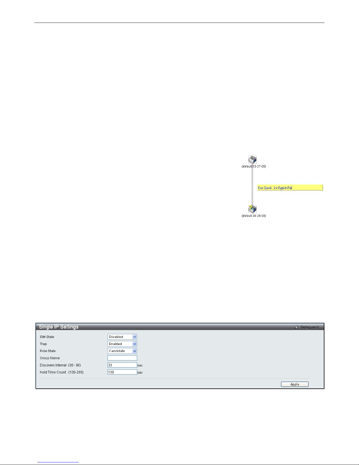
xStack® DGS-3200 Series Layer 2 Gigabit Ethernet Managed Switch
50
When a CaS becomes a MS, it autom atically becomes a m ember of t he first SNMP community (including read/write and rea d
only) to which the CS b elongs. However, if a MS h as its own IP address, it can belong to SNMP co mmunities to which other
switches in the group, including the CS, do not belong.
Upgrade to v1.61
To better i mprove SIM m anagement, t he DGS-3200 Series swi tches have been upgraded to version 1.61 in t his release. Many
improvements have been made, including:
4. The Commander Switch (CS) now has the capability to automatically rediscover member switches that have left the SIM
group, either through a reboot or web malfunction. This feature is accomplished through the use of Discover packets and
Maintenance packets that previously set SIM members will emit after a reboot. Once a MS has had its MAC address and
password saved to the CS’s database, if a reboot occurs in the MS, the CS will keep this MS information in its database
and when a MS has been rediscovered, it will add the MS back into the SIM tree automatically. No configuration will be
necessary to rediscover these switches.
There are some instances where pre-saved MS switches cannot be rediscovered. For example, if the Switch is still powered down,
if it has bec ome the member of another group, or if it has been configured to be a Commander Switch, the rediscovery process
cannot occur.
2. T h
e t opology m ap no w i ncludes ne w feat ures f or connections t hat are a
member of a port trunking group. It will display the speed and number of Ethernet
connections creating this port trunk group, as shown in the adjacent picture.
5. This v
ersion will support switch upload and downloads for firmware, configuration files and log files, as follows:
Firmware – The switch now supports MS firmware downloads from a TFTP server.
Configuration Files – Thi s switch no w sup ports d ownloading and upl oading of con figuration fi les both to (f or
configuration restoration) and from (for configuration backup) MS’s, using a TFTP server.
Log – The Switch now supports uploading MS log files to a TFTP server.
6. The user m ay zo om in and zo om ou t when u tilizing t he t opology wi ndow to get a better, m ore defined view of the
configurations.
Single IP Settings
The Switch is set as a Candidate (CaS) as the factory default configuration and Single IP Management is disabled.
To enable SIM for the Switch using the Web interface, click Configuration > Single IP Management > Single IP Settings:
Figure 2 - 51. Single IP Settings window for Candidate (Disabled)
Change the SIM State to Enabled using the drop-down menu and click Apply. The window will then refresh and the Single IP
Settings window will look like this:
Page 64

xStack® DGS-3200 Series Layer 2 Gigabit Ethernet Managed Switch
51
Figure 2 - 52. Single IP Settings window for Candidate (Enabled)
Parameter Description
SIM State Use the drop-down menu to either enable or disable the SIM state on the Switch. Disabled will
render all SIM functions on the Switch inoperable.
Trap Use the drop-down menu to either enable or disable a trap. This is designed to control the
sending of traps issued from a member switch.
Role State
Use the drop-down menu to change the SIM role of the Switch. The two choices are:
Candidate – A Candidate Switch (CaS) is not the member of a SIM group but is connected to
a Commander Switch. This is the default setting for the SIM role of the Switch.
Commander – Choosing this parameter will make the Switch a Commander Switch (CS). The
user may join other switches to this Switch, over Ethernet, to be part of its SIM group.
Choosing this option will also enable the Switch to be configured for SIM.
Group Name
Enter a Group Name in this textbox. This is optional.
Discovery Interval
(30-90)
The user may set the discovery protocol interval, in seconds that the Switch will send out
discovery packets. Returning information to a Commander Switch will include information
about other switches connected to it. (Ex. MS, CaS). The user may set the Discovery Interval
from 30 to 90 seconds. The default value is 30 seconds.
Hold Time Count
(100-255)
This parameter may be set for the time, in seconds; the Switch will hold information sent to it
from other switches, utilizing the Discovery Interval. The user may set the hold time from 100
to 255 seconds. The default value is 100 seconds.
Click Apply to im plement t he settin gs chan ged. After en abling th e Switch to be a Commander Switch (CS), the Single I P
Management folder will th en contain four added links to aid the user in configuring SIM through the web, including Topology,
Firmware Upgrade, Configuration Backup/Restore and Upload Log. The Single IP Settings window should look like this:
Figure 2 - 53. Single IP Settings window for Commander (Enabled)
Page 65
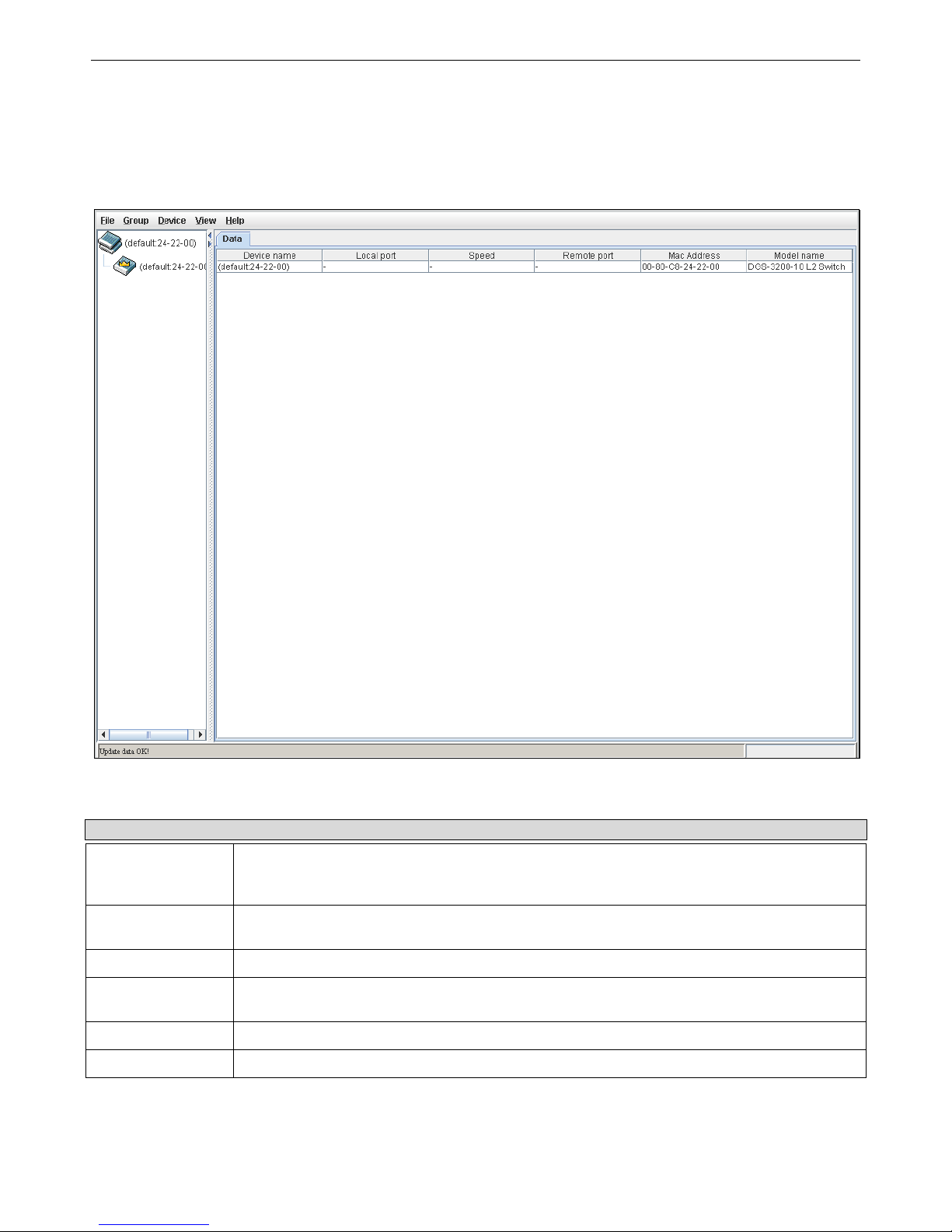
xStack® DGS-3200 Series Layer 2 Gigabit Ethernet Managed Switch
52
Topology
This window will be used to configure and manage the Switch within the SIM group and requires Java script to function properly
on your computer.
The Java Runtime Environment on your server should initiate and lead you to the Topology window, as seen below.
Figure 2 - 54. Topology window
The Topology window holds the following information on the Data tab:
Parameter Description
Device Name
This field will display the Device Name of the switches in the SIM group configured by the user.
If no device is configured by the name, it will be given the name default and tagged with the
last six digits of the MAC Address to identify it.
Local Port
Displays the number of the physical port on the CS that the MS or CaS is connected to. The
CS will have no entry in this field.
Speed
Displays the connection speed between the CS and the MS or CaS.
Remote Port
Displays the number of the physical port on the MS or CaS to which the CS is connected. The
CS will have no entry in this field.
MAC Address
Displays the MAC Address of the corresponding Switch.
Model Name
Displays the full Model Name of the corresponding Switch.
To view the To pology V iew window, open the View drop-down menu in the toolbar and then click Topology, which will open
the following Topology Map. This window will refresh itself periodically (20 seconds by default).
Page 66
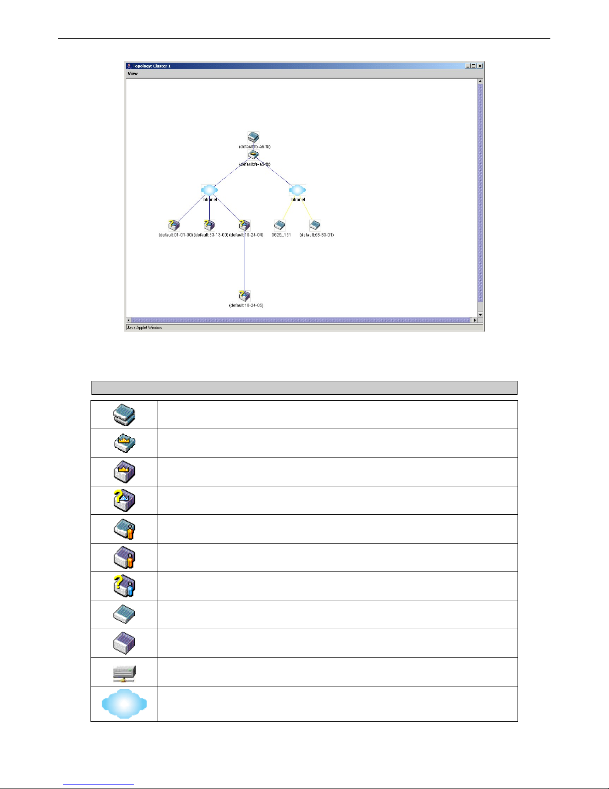
xStack® DGS-3200 Series Layer 2 Gigabit Ethernet Managed Switch
53
Figure 2 - 55. Topology View window
This window will display how the devices within the Single IP Management Group connect to other groups and devices. Possible
icons on this window are as follows:
Icon Description
Group
Layer 2 commander switch
Layer 3 commander switch
Commander switch of other group
Layer 2 member switch.
Layer 3 member switch
Member switch of other group
Layer 2 candidate switch
Layer 3 candidate switch
Unknown device
Non-SIM devices
Page 67
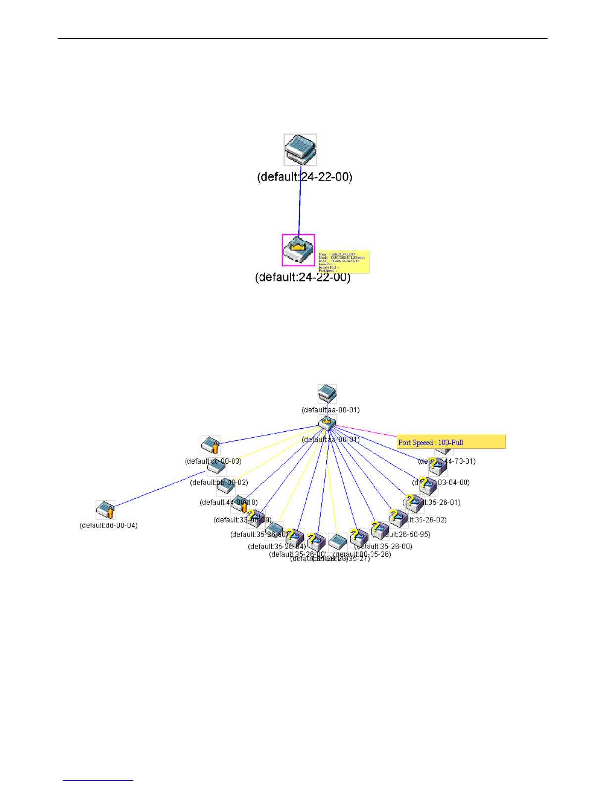
xStack® DGS-3200 Series Layer 2 Gigabit Ethernet Managed Switch
54
Tool Tips
In the Topology view window, the mouse plays an important role in configuration and in viewing device information. Setting the
mouse cursor over a specific device in the topology window (tool tip) will display the same information about a specific device as
the Tree view does. See the window below for an example.
Figure 2 - 56. Device Information Utilizing the Tool Tip
Setting the mouse cursor over a lin e between two devices will display the con nection speed between the two devices, as shown
below.
Figure 2 - 57. Port Speed Utilizing the Tool Tip
Right-Click
Right-clicking on a device will allow the user to perform various functions, depending on the role of the Switch in the SIM group
and the icon associated with it.
Page 68
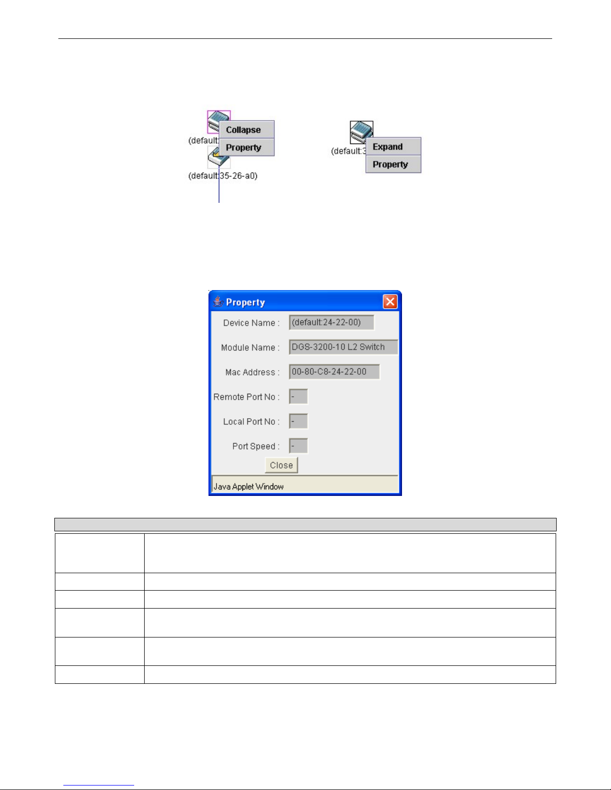
xStack® DGS-3200 Series Layer 2 Gigabit Ethernet Managed Switch
55
Group Icon
Figure 2 - 58. Right-Clicking a Group Icon
The following options may appear for the user to configure:
Collapse – To collapse the group that will be represented by a single icon.
Expand – To expand the SIM group, in detail.
Property – To pop up a window to display the group information.
Figure 2 - 59. Property window
Parameter Description
Device Name
This field will display the Device Name of the switches in the SIM group configured by the user.
If no Device Name is configured by the name, it will be given the name default and tagged with
the last six digits of the MAC Address to identify it.
Module Name
Displays the full module name of the switch that was right-clicked.
MAC Address
Displays the MAC Address of the corresponding Switch.
Remote Port No.
Displays the number of the physical port on the MS or CaS that the CS is connected to. The CS
will have no entry in this field.
Local Port No.
Displays the number of the physical port on the CS that the MS or CaS is connected to. The CS
will have no entry in this field.
Port Speed
Displays the connection speed between the CS and the MS or CaS
Page 69
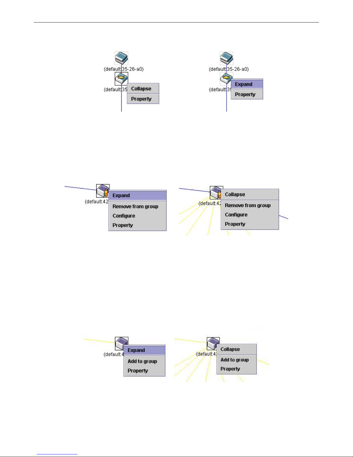
xStack® DGS-3200 Series Layer 2 Gigabit Ethernet Managed Switch
56
Commander Switch Icon
Figure 2 - 60. Right-Clicking a Commander Icon
The following options may appear for the user to configure:
Collapse – To collapse the group that will be represented by a single icon.
Expand – To expand the SIM group, in detail.
Property – To pop up a window to display the group information.
Member Switch Icon
Figure 2 - 61. Right-Clicking a Member icon
The following options may appear for the user to configure:
Collapse – To collapse the group that will be represented by a single icon.
Expand – To expand the SIM group, in detail.
Remove from group – Remove a member from a group.
Configure – Launch the web management to configure the Switch.
Property – To pop up a window to display the device information.
Candidate Switch Icon
Figure 2 - 62. Right-Clicking a Candidate icon
The following options may appear for the user to configure:
Collapse – To collapse the group that will be represented by a single icon.
Expand – To expand the SIM group, in detail.
Page 70

xStack® DGS-3200 Series Layer 2 Gigabit Ethernet Managed Switch
57
Add to group – Add a candidate to a group. Clicking this option will reveal the following dialog box for the user to enter a
password for au thentication fro m the Candidate Switch befo re being ad ded to th e SI M group. Click OK t o enter th e
password or Cancel to exit the dialog box.
Figure 2 - 63. Input password dialog box
Property – To pop up a window to display the device information.
Menu Bar
The Single IP Management window contains a menu bar for device configurations, as seen below.
Figure 2 - 64. Menu Bar of the Topology View
The five menus on the menu bar are as follows.
File
Print Setup – Will view the image to be printed.
Print Topology – Will print the topology map.
Preference – Will set display properties, such as polling interval, and the views to open at SIM startup.
Group
Add to group – Add a candidate to a group. Clicking this option will reveal the following dialog box for the user to enter a
password for au thentication fro m the Candidate Switch befo re being ad ded to th e SI M group. Click OK t o enter th e
password or Cancel to exit the dialog box.
Figure 2 - 65. Input password dialog box
Remove from Group – Remove an MS from the group.
Device
Configure – Will open the Web manager for the specific device.
View
Refresh – Update the views with the latest status.
Topology – Display the Topology view.
Help
About – Will display the SIM information, including the current SIM version.
Page 71
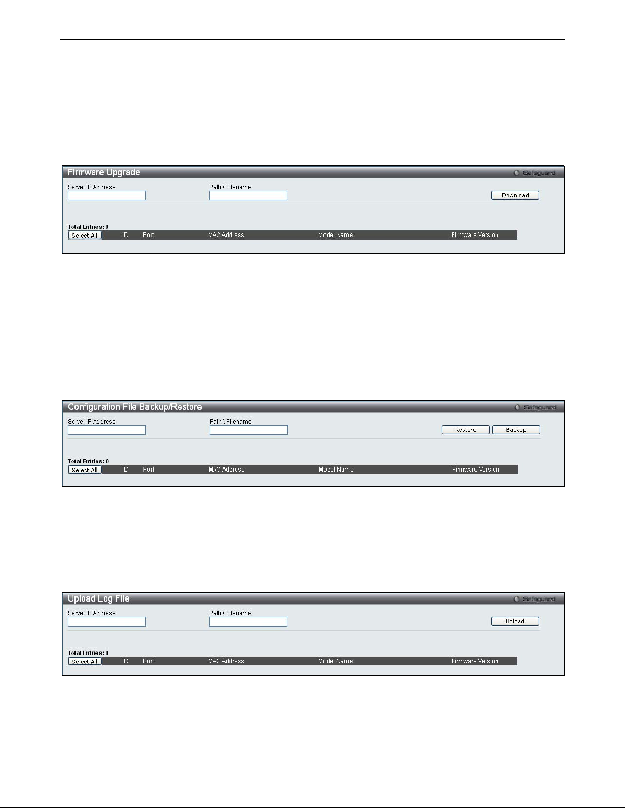
xStack® DGS-3200 Series Layer 2 Gigabit Ethernet Managed Switch
58
Firmware Upgrade
The Commander Switch may be used for firmware upgrades of member switches. Member Switches will be listed in the table and
will be specified by Port (port o n the CS wh ere the MS resides), MAC Address, Model Name and Version. To specify a certain
Switch for firmware download, click its corresponding check box under the Port heading. To update the firmware, enter the Server
IP Address where the firmware resides and enter the Path/Filename of the firmware. Click Download to initiate the file transfer.
To view the following window, click Configuration > Single IP Management > Firmware Upgrade:
Figure 2 - 66. Firmware Upgrade window for Single IP Management
Configuration File Backup/Restore
The Commander Switch can instruct configuration file backup and restore to the Mem ber Switch using a TFTP server. Member
Switches will be listed in the ta ble and will b e sp ecified by Port (port on the CS where the MS resi des), MAC Address, Model
Name and Version. To sp ecify a certain Switch for upgrading configuration files, click its corresponding radio button under the
Port heading. To update the configuration file, enter the Server IP Address where the file resides and enter the Pat h/Filename of
the configuration file. Click Restore to initiate the file tran sfer from a TFTP serv er to the Switch. Click Backup to backup the
configuration file to a TFTP server.
To view the following window, click Configuration > Single IP Management > Configuration File Backup/Restore:
Figure 2 - 67. Configuration File Backup/Restore window for Single IP Management
Upload Log File
The Commander Switch can order a log file from a member switch sent to a server. Provide the Server IP address for storing the
log and the log file path and filename on the member switch. Click Upload to send the log file to a TFTP server.
To view the following window, click Configuration > Single IP Management > Upload Log File:
Figure 2 - 68. Upload Log File window for Single IP Management
Page 72
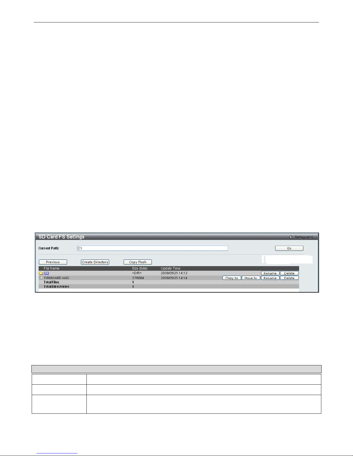
xStack® DGS-3200 Series Layer 2 Gigabit Ethernet Managed Switch
59
SD Card FS Settings
Users can plug an SD f lash car d i nto a front sl ot on th e D GS-3200-24 ( DGS-3200-10 and DGS-3200-16 do no t support th is
feature). The SD flash card allows users to carry out the following:
Save the Switch log to the SD card
Save the Switch configuration to the SD card
Save the Switch Runtime image to the SD card
Save the Switch Prom image to the SD card
Copy images from the SD card to the flash memory on the Switch to replace Runtime image 1 or Runtime image 2
Copy configuration files from the SD card to the flash memory on the Switch to replace configuration 1 or configuration 2
Replace the Prom image by copying a Prom image from the SD card to the flash memory
Download Runtime image and save to the SD card
Download configuration and save to the SD card
Access the files on the SD card via a PC (e.g. using Microsoft Windows)
Boot up the Switch using a runtime image stored on the SD card
Boot up the Switch using a configuration stored on the SD card
SD card is hot swappable
Switch automatically creates new directories an d files automatically o n the SD card. A warn ing message will display if
there is an existing file or folder with the same name, asking the user to overwrite or keep the existing file or folder
To view the following window, click Configuration > SD Card FS Settings:
Figure 2 - 69. SD Card FS Settings window
To use a firmware image and configuration on an SD card, carry out the following steps:
1. Insert the SD flash card into the SD card slot on the front of the Switch.
2. Type the path of the firmware image in the Current Path field.
3. Click Go.
In addition to using a firmware image and configuration from an SD flash card, the SD Card FS Settings window allows users to
manage t he directories an d files st ored on the S D ca rd. The t able bel ow describes t he b uttons used t o m anage t he fi les an d
directories, stored on the SD flash card.
Parameter Description
Previous
Click this button to navigate to the previous folder.
Create Directory
Click this button to create a new directory.
Copy Flash
Click this button to copy files from/to the SD Flash card or internal Flash memory.
Page 73

xStack® DGS-3200 Series Layer 2 Gigabit Ethernet Managed Switch
60
Format
If you have inserted a new SD Flash card this button will appear.
Click this button to format the new SD Flash card.
Copy to
Click this button to copy a file to another location.
Move to
Click this button to move a file to another location.
Rename
Click this button to rename the corresponding file or folder.
Delete
Click this button to delete the corresponding file or folder.
Page 74
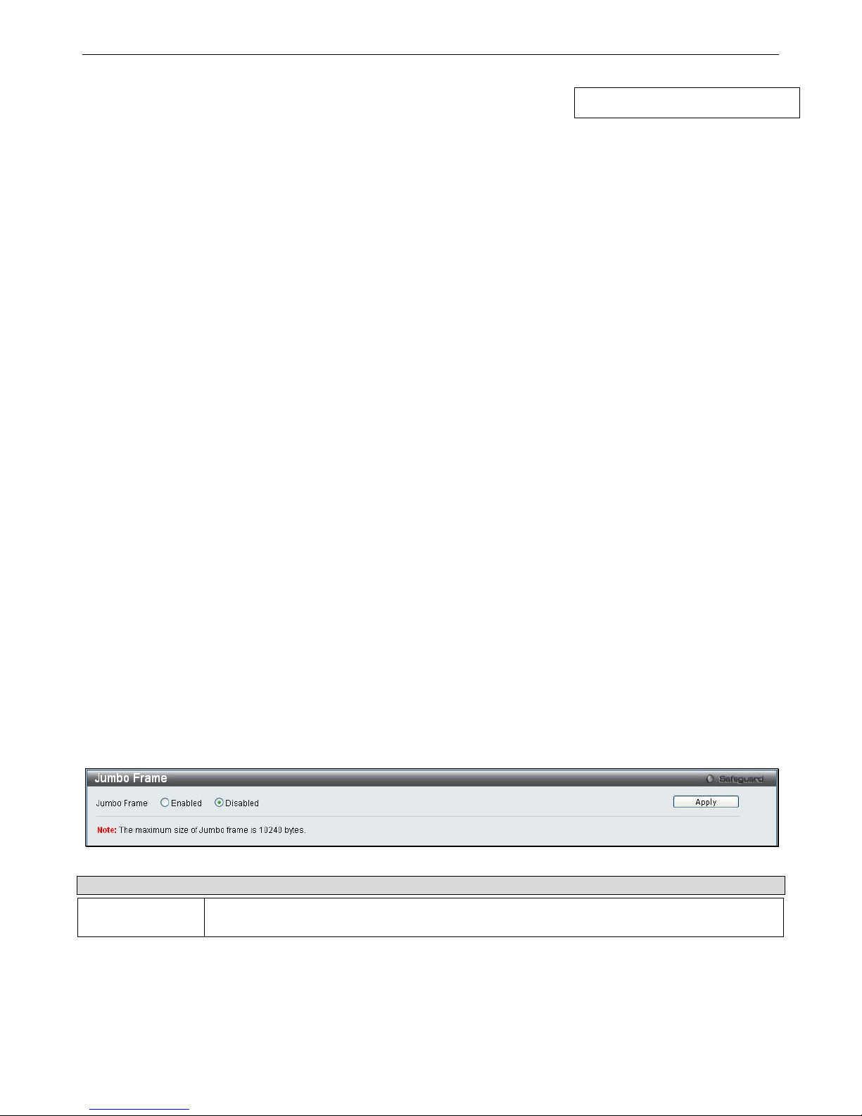
xStack® DGS-3200 Series Layer 2 Gigabit Ethernet Managed Switch
61
Section 3
L2 Features
Jumbo Frame
Egress Filter Settings
802.1Q VLAN
Private VLAN Settings
802.1v Protocol VLAN
MAC-based VLAN Settings
GVRP Settings
PVID Auto Assign Settings
Port Trunking
VLAN Trunk Settings
LACP Port Settings
Traffic Segmentation
IGMP Snooping
MLD Snooping Settings
Port Mirroring
Loopback Detection Settings
Spanning Tree
Forwarding & Filtering
Th
e fo
llowing section will aid the user in configuring security functions for the Switch. The Switch includes various functions for
VLAN, Trunking, IGMP Snooping, MLD Snooping, Spanning Tree, and Forwarding & Filtering, all discussed in detail.
Jumbo Frame
The S witch s upports j umbo fram es. Jum bo fram es are Et hernet fram es wi th m ore t han 1 ,500 by tes of payload. The S witch
supports jumbo frames with a maximum frame size of 10240 bytes.
To view the following window, click L2 Features > Jumbo Frame:
Figure 3 - 1. Jumbo Frame window
Parameter Description
Jumbo Frame
This field will enable or disable the Jumbo Frame function on the Switch. The default is
Disabled. The maximum frame size is 10240 bytes.
To enable or disable Jumbo Frame, use the radio button and click Apply.
Page 75
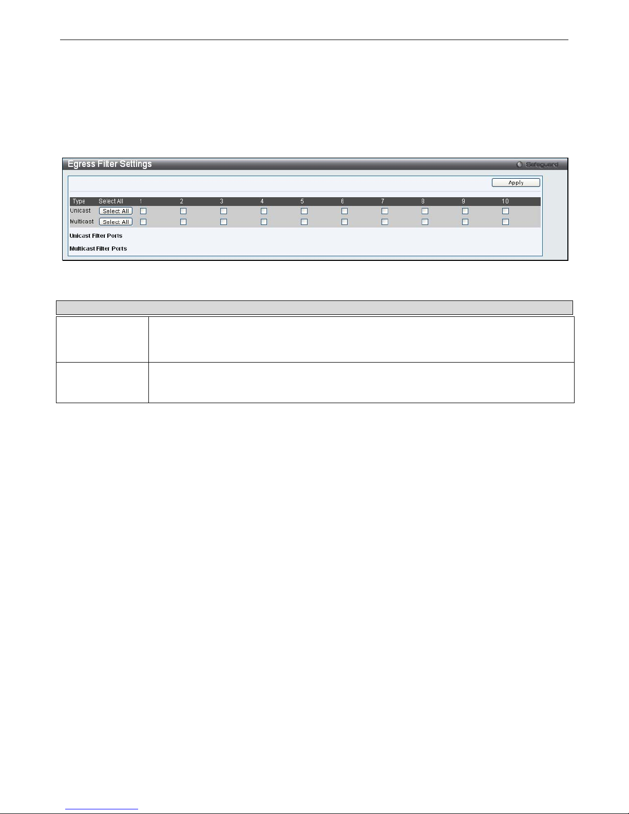
xStack® DGS-3200 Series Layer 2 Gigabit Ethernet Managed Switch
62
Egress Filter Settings
Users can configure an egress filter on specific ports for unknown unicast and unregistered multicast packets.
The Switch drops all unk nown unicast/multicast packets on egress ports when it dete cts un known unicast/multicast packets for
egress ports. Therefore, a user can select which port is permitted or not permitted to receive unknown unicast/multicast packets.
To view the following window, click L2 Features > Egress Filter Settings:
Figure 3 - 2. Egress Filter Settings window
The following fields can then be set:
Parameter Description
Unicast
Select ports to filter unknown unicast packets. These packets will not be forwarded to those
ports. Unselected ports will not filter unknown unicast packets and the packets may be forwarded
to those ports.
Multicast
Select ports to filter unregistered multicast packets. These packets will not be forwarded to those
ports. Unselected ports will not filter unregistered multicast packets and the packets may be
forwarded to those ports.
Click Apply to implement changes made.
802.1Q VLAN
Understanding IEEE 802.1p Priority
Priority tagging is a function defined by the IEEE 802.1p standard designed to provide a means of managing traffic on a network
where many differen t types of data m ay be transmitted simultaneously. It is in tended to alleviate problems asso ciated with th e
delivery of time critical d ata over congested networks. The quality of applicatio ns th at are dependent on such time critical d ata,
such as video conferencing, can be severely and adversely affected by even very small delays in transmission.
Network devices th at are in compliance with th e IEEE 80 2.1p sta ndard h ave t he ability to recognize the p riority lev el of d ata
packets. These de vices can a lso as sign a priority lab el or tag to packets. C ompliant devices ca n al so st rip priority t ags f rom
packets. This priority tag determines the packet’s degree of expeditiousness and determines the queue to which it will be assigned.
Priority t ags are gi ven values from 0 t o 7 wi th 0 being assigned t o the lowest priority data and 7 as signed to the highest. T he
highest priority tag 7 is generally only used for data associated with video or audio applications, which are sensitive to even slight
delays, or for data from specified end users whose data transmissions warrant special consideration.
The Switch allows you to fu rther tailor how p riority tagged data packets are han dled on your network. Using queues to manage
priority tagged data allows you to specify its relative priority to suit the needs of your network. There may be circumstances where
it wo uld be ad vantageous t o group t wo or more di fferently t agged packets i nto the sa me queue. Ge nerally, however, i t is recommended that the highest priority queue, Queue 7, be reserved for data packets with a priority value of 7. Packets that have not
been given any priority value are placed in Queue 0 and thus given the lowest priority for delivery.
Strict mode and weighted round robin system are employed on the Switch to determine the rate at which the queues are emptied of
packets. The ratio used for clearing the queues is 4:1. This means that the highest priority queue, Queue 7, will clear 4 packets for
every 1 packet cleared from Queue 0.
Remember, the p riority queue settings on the Switch are for all po rts, and all devices connected to the Switch will be affected.
This priority qu euing system will b e esp ecially b eneficial if you r network em ploys switch es with t he cap ability o f assign ing
priority tags.
Page 76

xStack® DGS-3200 Series Layer 2 Gigabit Ethernet Managed Switch
63
VLAN Description
A Virtual Local Area Network (VLAN) is a network topology configured according to a l ogical scheme rather than the physical
layout. VLANs can be used to combine any collection of LAN segments into an autonomous user group that appears as a si ngle
LAN. VLANs also logically segment th e network into different broadcast domains so that packets are forwarded only between
ports within the VLAN. Typically, a VLAN corresponds to a particular subnet, although not necessarily.
VLANs can enhance performance by conserving bandwidth, and improve security by limiting traffic to specific domains.
A VLAN is a collection of end nodes grouped by logic instead of physical location. End nodes that frequently communicate with
each other are assigned to the same VLAN, regardless of where they are physically on the network. Logically, a VL AN can be
equated to a broadca st domain, because broadcast packets are forwarded to only members of th e VLAN on which t he broadcast
was initiated.
Notes about VLANs on the Switch
No matter what basis is used to uniquely identify end nodes and assign these nodes VLAN membership, packets cannot
cross VLANs without a network device performing a routing function between the VLANs.
The Switch supports I EEE 802.1Q VLANs. Th e por t un tagging function ca n be used to rem ove the 802.1Q t ag from
packet headers to maintain compatibility with devices that are tag-unaware.
The Switch’s default is to assign all ports to a single 802.1Q VLAN named “default.”
The “default” VLAN has a VID = 1.
The member ports of Port-based VLANs may overlap, if desired.
IEEE 802.1Q VLANs
Some relevant terms:
Tagging – The act of putting 802.1Q VLAN information into the header of a packet.
Untagging – The act of stripping 802.1Q VLAN information out of the packet header.
Ingress port – A port on a switch where packets are flowing into the Switch and VLAN decisions must be made.
Egress p ort – A por t on a sw itch where packets are flowing out of the Switch, either to an other switch or to a n en d
station, and tagging decisions must be made.
IEEE 802.1Q (tagged) VLANs are implemented on the Switch. 802.1Q VLANs require tagging, which enables them to span the
entire network (assuming all switches on the network are IEEE 802.1Q-compliant).
VLANs allow a network to be segmented in order to reduce the size of broadcast domains. All packets entering a VLAN will only
be forwarded to the stations (over IEEE 802.1Q enabled switches) that are members of that VLAN, and this includes broadcast,
multicast and unicast packets from unknown sources.
VLANs can also provide a level of security to your network. IEEE 802.1Q VLANs will only deliver packets between stations that
are members of the VLAN.
Any port can be configured as either tagging or untagging. The untagging feature of IEEE 802.1Q VLANs allows VLANs to work
with leg acy switch es that don’t recognize VLAN tag s i n packet headers. Th e tag ging feature allows VLANs to sp an m ultiple
802.1Q-compliant swi tches through a si ngle physical connection and allows Spanning Tree to be enabled on all ports and work
normally.
The IEEE 802.1Q standard restricts the forwarding of untagged packets to the VLAN the receiving port is a member of.
The main characteristics of IEEE 802.1Q are as follows:
Assigns packets to VLANs by filtering.
Assumes the presence of a single global spanning tree.
Uses an explicit tagging scheme with one-level tagging.
802.1Q VLAN Packet Forwarding
Packet forwarding decisions are made based upon the following three types of rules:
Ingress rules – rules relevant to the classification of received frames belonging to a VLAN.
Page 77
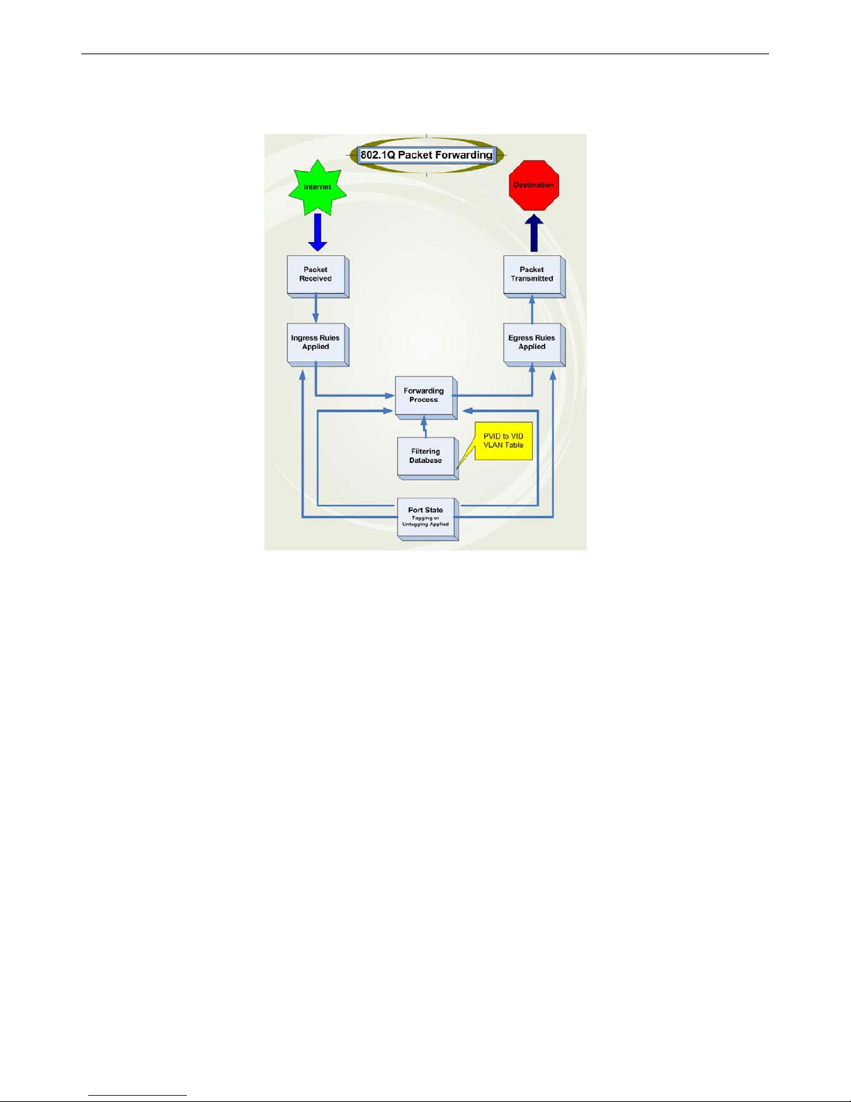
xStack® DGS-3200 Series Layer 2 Gigabit Ethernet Managed Switch
64
Forwarding rules between ports – decides whether to filter or forward the packet.
Egress rules – determines if the packet must be sent tagged or untagged.
Figure 3 - 3. IEEE 802.1Q Packet Forwarding
802.1Q VLAN Tags
The figure below shows t he 802.1Q V LAN tag. T here are fo ur additional octets inserted after the s ource MAC a ddress. Their
presence is indicated by a value of 0x8100 in the EtherType field. When a packet’s EtherType field is equal to 0x8100, the packet
carries the IEEE 802.1Q/802.1p tag. The tag is contained in the following two octets and consists of 3 bits of user priority, 1 bit of
Canonical Format Identifier (CFI – used for encapsulating Token Ring packets so they can be carried across Ethernet backbones),
and 12 bits of VLAN ID (VID). The 3 bits of user priority are used by 802.1p. The VID is the VLAN identifier and is used by the
802.1Q standard. Because the VID is 12 bits long, 4094 unique VLANs can be identified.
The tag is in serted into the packet header making the entire packet longer by 4 octets. All of the information originally contained
in the packet is retained.
Page 78
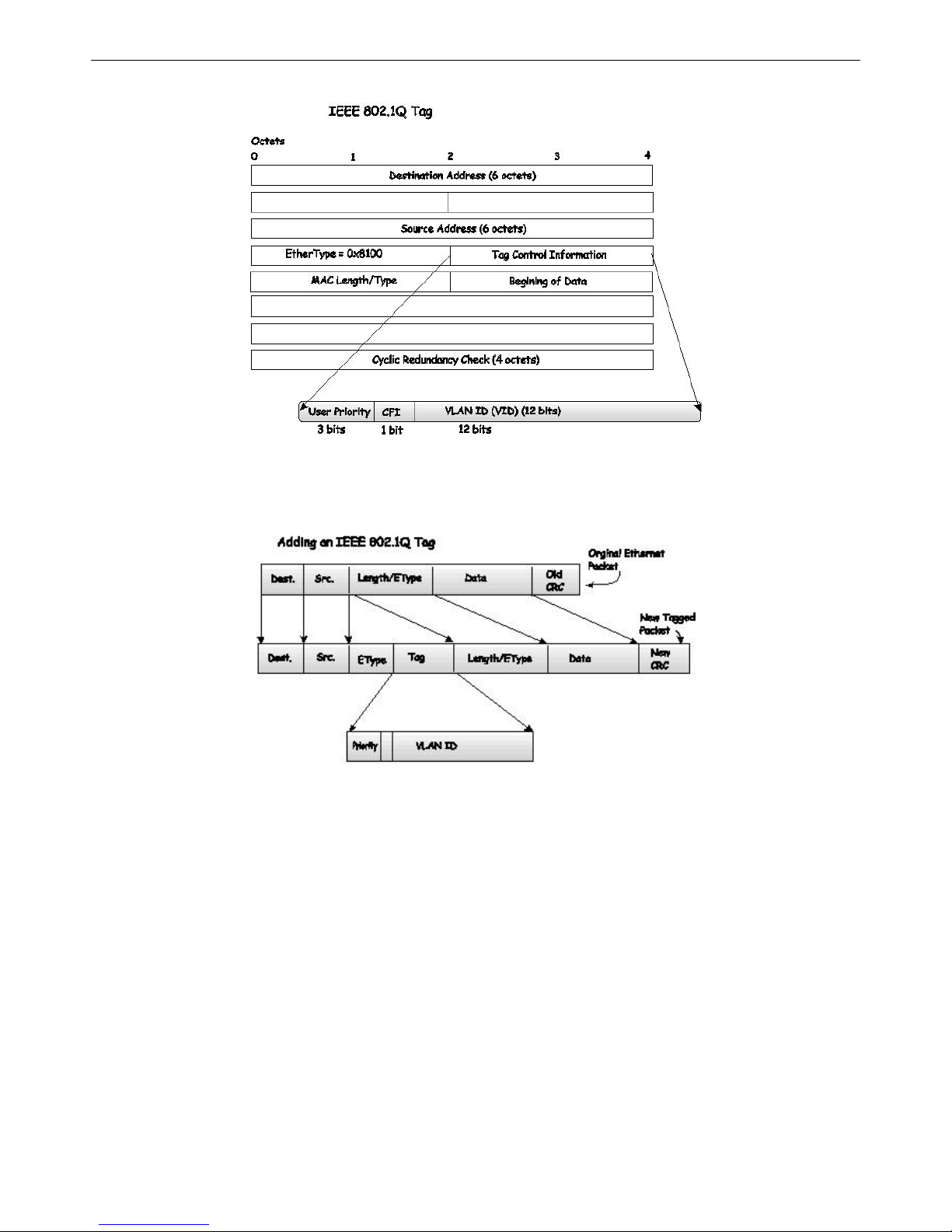
xStack® DGS-3200 Series Layer 2 Gigabit Ethernet Managed Switch
65
Figure 3 - 4. IEEE 802.1Q Tag
The EtherType and VLAN ID a re inserted after t he MAC source address, but before the original EtherType/Length or L ogical
Link C ontrol. Because the packet is now a bit longer than it was originally, the Cyclic Redunda ncy Check (CRC) m ust be
recalculated.
Figure 3 - 5. Adding an IEEE 802.1Q Tag
Port VLAN ID
Packets that are tagged (are carrying the 802.1Q VID information) can be transmitted from one 802.1Q compliant network device
to ano ther wit h th e VLAN i nformation in tact. Th is allows 802 .1Q VLANs to sp an n etwork dev ices (and ind eed, th e en tire
network, if all network devices are 802.1Q compliant).
Unfortunately, not all network devices are 802.1Q compliant. These devices are refe rred to as tag-una ware. 802.1Q devices are
referred to as tag-aware.
Prior to the adoption of 802.1Q VLANs, port-based and MAC-based VLANs were in common use. These VLANs relied upon a
Port VLAN ID (PVID) to forward packets. A packet received on a given port would be assigned that port’s PVID and then be
forwarded to the port that corresponded to the packet’s destination address (found in the Switch’s forwarding table). If the PVID
of the port that received the packet is di fferent from the PVID of the port that is to tra nsmit the packet, the Switch will drop the
packet.
Within the Switch, different PVIDs mean different VLANs (remember that two VLANs cannot communicate without an external
router). So, VLAN identification based upon the PVIDs cannot create VLANs that extend outside a given switch (or switch stack).
Every physical port on a switch has a PVID. 802.1Q ports are also assigned a PVID, for use within the Switch. If no VLANs are
defined on the Switch, all ports are then assigned to a default VLAN with a PVID equal to 1. Untagged packets are assigned the
PVID of the port on which they were received. Forwarding decisions are based upon this PVID, in so far as VLANs are concerned.
Page 79

xStack® DGS-3200 Series Layer 2 Gigabit Ethernet Managed Switch
66
Tagged packets are forwarded according to the VID c ontained within the tag. Ta gged packets are als o assigned a PVID, but the
PVID is not used to make packet-forwarding decisions, the VID is.
Tag-aware switch es must keep a tab le to relate PVIDs wit hin the Switch to VIDs on the n etwork. The Switch will compare the
VID of a packet to be transmitted to the VID of th e port that is to transmit the packet. If t he two VIDs are d ifferent, the Switch
will drop the packet. Because of the existence of th e PVID for untagged packets and the VID fo r tagged packets, tag-aware and
tag-unaware network devices can coexist on the same network.
A switch port can have only one PVID, but can have as many VIDs as the Switch has memory in its VLAN table to store them.
Because s ome devices on a network may be tag-unaware, a decision must be made at each port on a tag-awa re de vice before
packets are tran smitted – sh ould th e p acket to b e tran smitted have a tag or not? If th e tran smitting po rt is co nnected to a tag unaware device, the packet should be untagged. If the transmitting port is con nected to a tag-aware device, the packet should be
tagged.
Tagging and Untagging
Every port on an 802.1Q compliant switch can be configured as tagging or untagging.
Ports with tagging enabled will put the VID number, priority and other VLAN information into the header of all packets that flow
into and out of it. If a packet has previously been tagged, the port will not alter th e packet, thus keeping the VLAN i nformation
intact. Other 802.1Q compliant devices on the network to make packet-forwarding decisions can then use the VLAN information
in the tag.
Ports with untagging enabled will strip the 802.1Q tag from all packets that flow into and out of those ports. If the packet doesn’t
have an 802.1Q VLAN tag, the port will no t alter the packet. Thus, all packets receive d by and forwarded by an untagging port
will have no 802.1Q VLAN information. (Remember that the PVID is only used internally within the Switch). Untagging is used
to send packets from an 802.1Q-compliant network device to a non-compliant network device.
Ingress Filtering
A port on a switch where packets are flowing into the Switch and VLAN decisions must be made is referred to as an ingress port.
If ing ress filtering is en abled for a po rt, the Switch will ex amine the VLAN i nformation in th e packet header (i f present) and
decide whether or not to forward the packet.
If the packet is tag ged with VLAN information, the ingress port will first determine if th e ingress port itself is a m ember of the
tagged VLAN. If it is no t, the packet will be dropped. If th e i ngress port is a m ember of t he 802.1Q VLAN, t he Switch th en
determines if the destination port is a m ember of the 802.1Q VLAN. If it is not, the packet is dr opped. If the destination port is a
member of the 802.1Q VLAN, the packet is forwarded and the destination port transmits it to its attached network segment.
If the packet is not tagged with VLAN information, the ingress port will tag the packet with its own PVID as a VID (if the port is
a tagging port). Th e switch then determ ines if t he destination port is a member of the same VLAN (has the same VID) as the
ingress port. If it does not, the packet is dropped. If it has the same VID, the packet is forwarded and the destination port transmits
it on its attached network segment.
This process is referred to as ingress filtering and is u sed to conserve bandwidth within the Switch by dropping packets that are
not on the same VLAN as the ingress port at the point of reception. This eliminates the subsequent processing of packets that will
just be dropped by the destination port.
Default VLANs
The Switch initially configures one VLAN, VID = 1, called “default.” The factory default setting assigns all ports on the Switch to
the “default.” As new VLANs are configured in Port-based mode, their respective member ports are removed from the “default.”
Packets cannot cross VLANs. If a member of one VLAN wants to connect to another VLAN, the link must be through an external
router.
NOTE: If no VLANs are configured on the Switch, then all packets will be forwarded to any
destination port. Packets with unknown source addresses will be flooded to all ports.
Broadcast and multicast packets will also be flooded to all ports.
Page 80

xStack® DGS-3200 Series Layer 2 Gigabit Ethernet Managed Switch
67
An example is presented below:
VLAN Name VID Switch Ports
System (default) 1 5, 6, 7
Engineering 2 9, 10
Sales 5 1, 2, 3, 4
Table 3 - 1. VLAN Example – Assigned Ports
Port-based VLANs
Port-based VLANs limit traffic th at flows into and out of switch ports. Thus, all devices connected to a port are m embers of the
VLAN(s) the port belongs to, whether there is a single computer directly connected to a switch, or an entire department.
On port-based VL ANs, NICs do not nee d to be a ble to i dentify 802.1Q tags i n packet heade rs. NICs send and receive normal
Ethernet packets. If the packet’s destination lies on the same segment, communications take place using normal Ethernet protocols.
Even though this is always the case, when the destination for a packet lies on another switch port, VLAN considerations come into
play to decide if the packet gets dropped by the Switch or delivered.
VLAN Segmentation
Take for exam ple a pac ket that is transm itted by a m achine on Port 1 t hat is a member of VLAN 2. If t he destination lies o n
another port (found through a normal forwarding table lookup), the Switch then looks to see if the other port (Port 10) is a member
of VLAN 2 (and can therefore receive VLAN 2 packets). If Port 10 is not a member of VLAN 2, then the packet will be dropped
by the Switch and will not reach its d estination. If Port 10 is a member of VLAN 2, the packet will g o through. This selective
forwarding feature based on VLAN criteria is how VLANs segment networks. The key point being that Port 1 will only transmit
on VLAN 2.
VLAN and Trunk Groups
The members of a trunk grou p have the same V LAN setting. Any VLAN setting on the m embers of a trunk group will apply to
the other member ports.
NOTE: In order to use VLAN segmentation in conjunction with port trunk groups, first set the
port trunk group(s), and then configure the VLAN settings. To change the port trunk grouping
with VLANs already in place it is unnecessary to reconfigure the VLAN settings after changing
the port trunk group settings. VLAN settings will automatically change in conjunction with the
change of the port trunk group settings.
Page 81
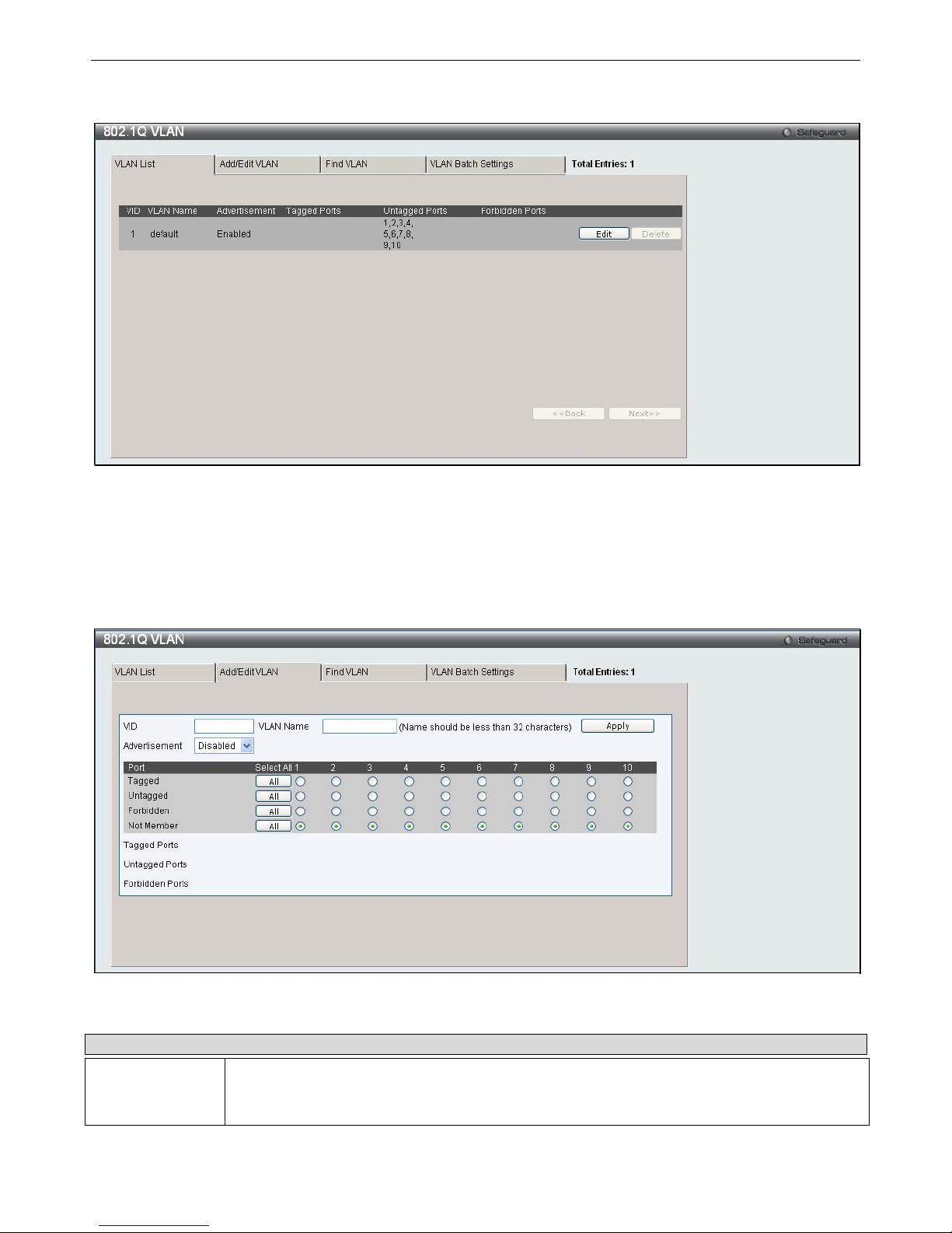
xStack® DGS-3200 Series Layer 2 Gigabit Ethernet Managed Switch
68
To view the following window, click L2 Features > 802.1Q VLAN:
Figure 3 - 6. VLAN List tab of the 802.1Q VLAN window
The VLAN List tab lists all previously configured VLANs by VLAN ID and VLAN Name. To delete an existing 802.1Q VLAN,
click the corresponding Delete button.
To create a new 802.1Q VLAN o r modify an existing 802.1Q VLAN, click the Add/Edit VLAN tab. A new tab will appear, as
shown below, to configure the port settings and to assign a unique name and number to the new VLAN. See the table on the next
page for a description of the parameters in the new window.
Figure 3 - 7. Add/Edit VLAN tab of the 802.1Q VLAN window
The following fields can then be set in the Add/Edit VLAN tab:
Parameter Description
VID (VLAN ID)
Allows the entry of a VLAN ID or displays the VLAN ID of an existing VLAN in the Add/Edit
VLAN tab. VLANs can be identified by either the VID or the VLAN name.
Page 82
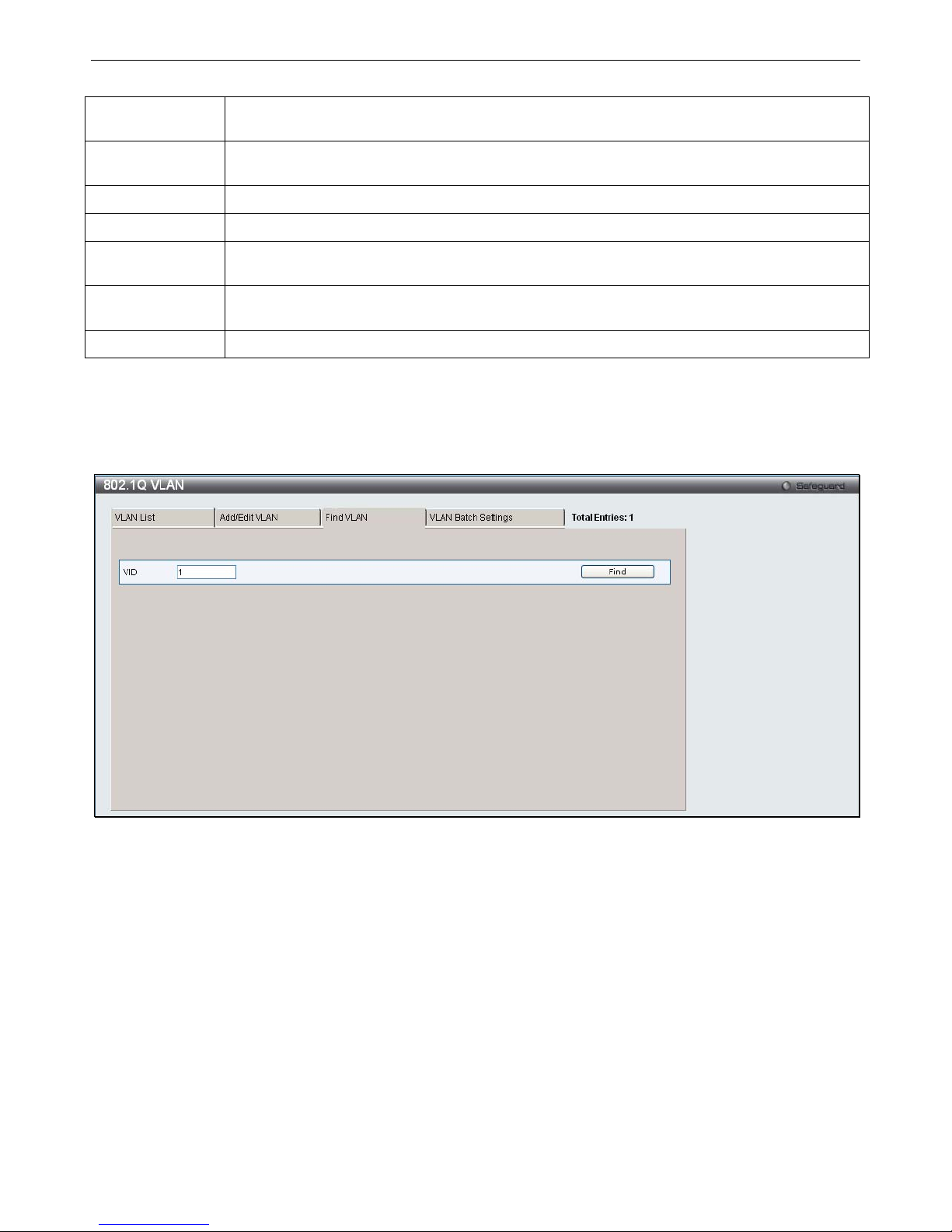
xStack® DGS-3200 Series Layer 2 Gigabit Ethernet Managed Switch
69
VLAN Name
Allows the entry of a name for the new VLAN or for editing the VLAN name in the Add/Edit
VLAN tab.
Advertisement
Enabling this function will allow the Switch to send out GVRP packets to outside sources,
notifying that they may join the existing VLAN.
Port
Shows all ports of the Switch for the 802.1Q configuration option.
Tagged
Specifies the port as 802.1Q tagging. Clicking the radio button will designate the port as tagged.
Untagged
Specifies the port as 802.1Q untagged. Clicking the radio button will designate the port as
untagged.
Forbidden
Click the radio button to specify the port as not being a member of the VLAN and that the port is
forbidden from becoming a member of the VLAN dynamically.
Not Member
Click the radio button to allow an individual port to be specified as a non-VLAN member.
Click Apply to implement changes made.
To search for a VLAN, click the
Find VLAN
tab. A new tab will appear, as shown below. Enter the VLAN ID number in the
field offered and then click the
Find
button. You will be redirected to the
VLAN List
tab. See the table on the next page for a
description of the parameters in the new window.
Figure 3 - 8. Find VLAN tab of the 802.1Q VLAN window
To create a VLAN Batch entry click the
VLAN Batch Settings
tab, as shown below.
Page 83
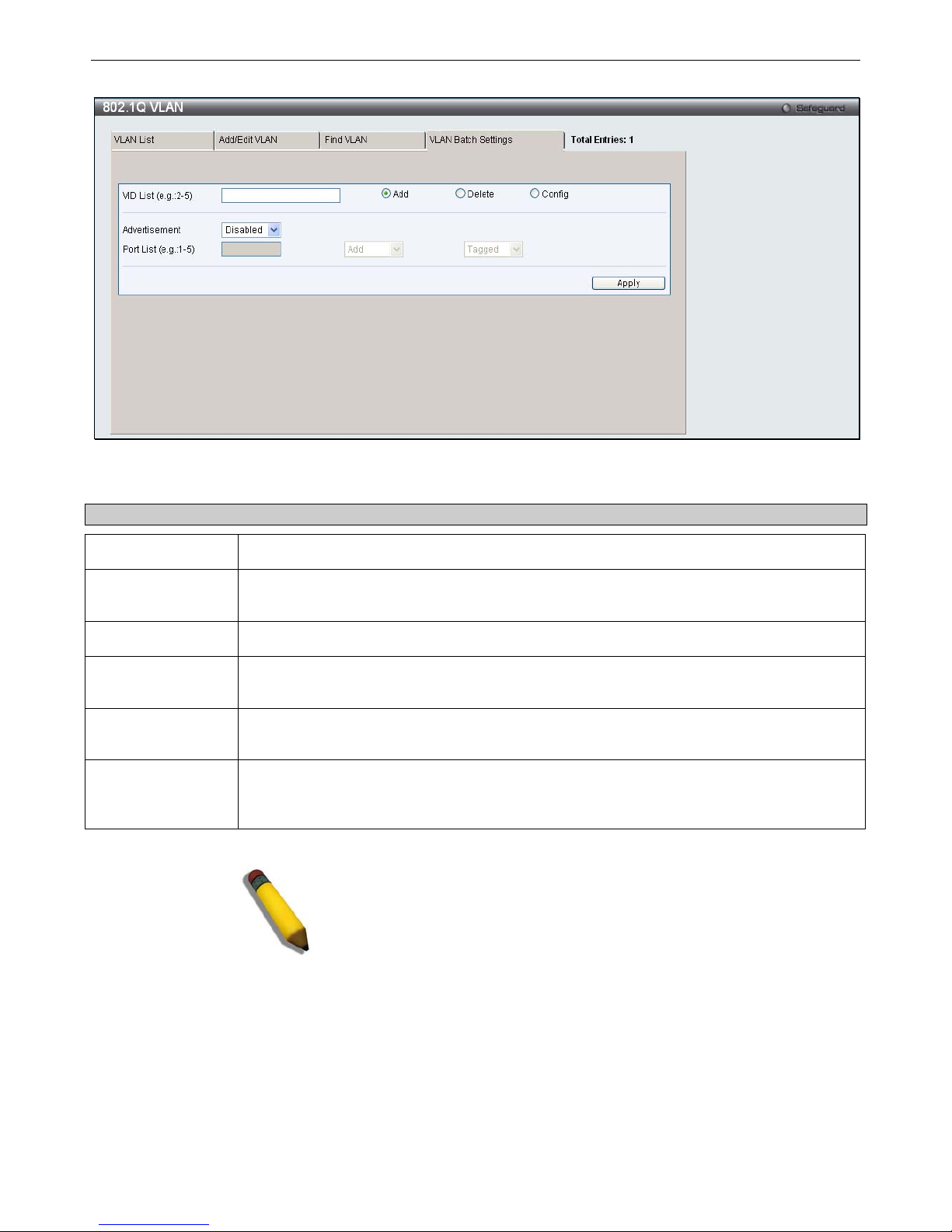
xStack® DGS-3200 Series Layer 2 Gigabit Ethernet Managed Switch
70
Figure 3 - 9. VLAN Batch Settings tab of the 802.1Q VLAN window
The following fields can be set in the VLAN Batch Settings windows:
Parameter Description
VID List (e.g. 2-5)
Enter a VLAN ID List that can be added, deleted or configured.
Advertisement
Enabling this function will allow the Switch to send out GVRP packets to outside sources,
notifying that they may join the existing VLAN.
Port List (e.g. 1-5)
Allows an individual port list to be added or deleted as a member of the VLAN.
Tagged
Specifies the port as 802.1Q tagged. Use the drop-down menu to designate the port as
tagged.
Untagged
Specifies the port as 802.1Q untagged. Use the drop-down menu to designate the port as
untagged.
Forbidden
Specifies the port as not being a member of the VLAN and that the port is forbidden from
becoming a member of the VLAN dynamically. Use the drop-down menu to designate the port
as forbidden.
Click Apply to implement changes made.
NOTE: The Switch supports up to 4k static VLAN entries.
Page 84
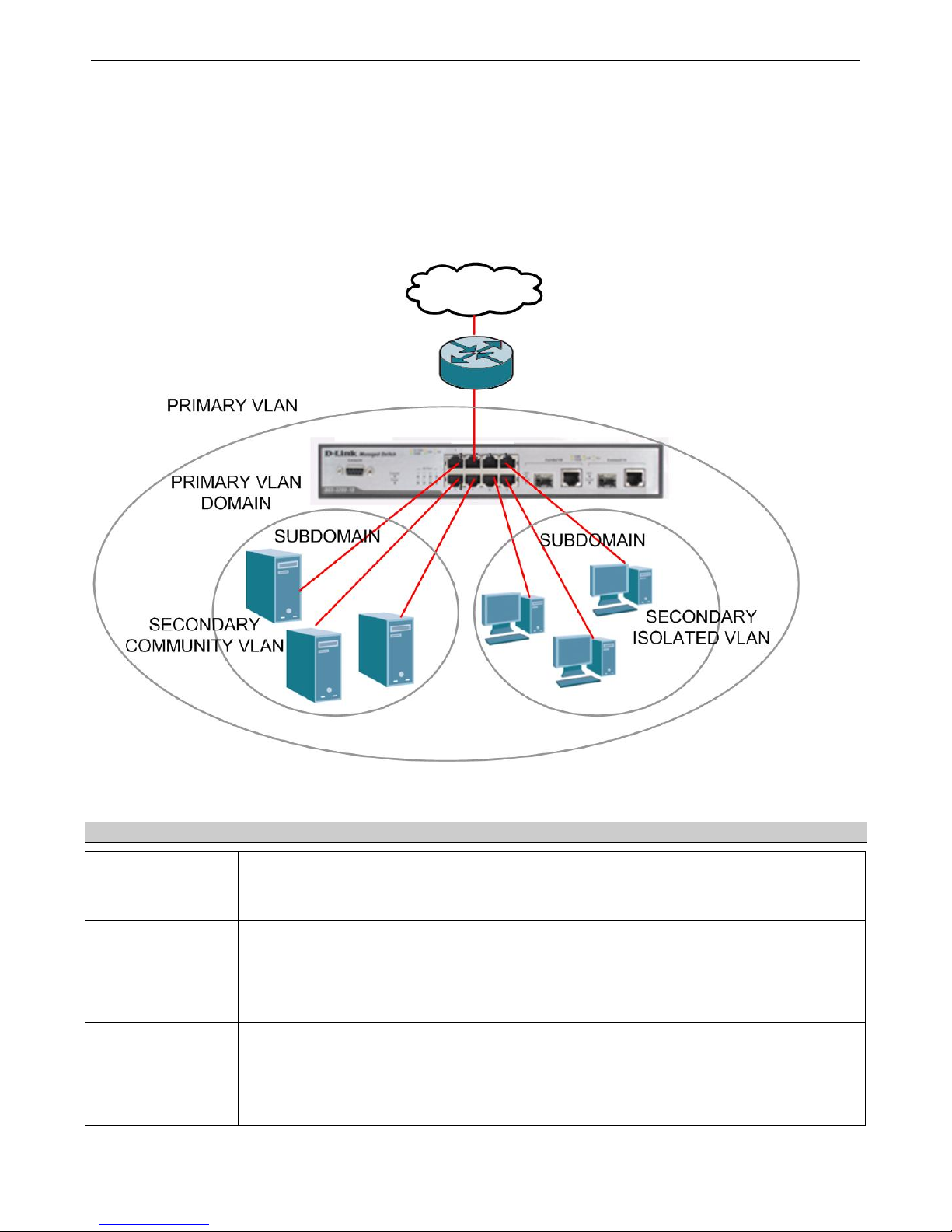
xStack® DGS-3200 Series Layer 2 Gigabit Ethernet Managed Switch
71
Private VLAN Settings
The Switch al lows users to create private VLA Ns. A p rivate VLA N divides the Layer 2 b roadcast domain of a VLA N into
subdomains and are particularly useful for service providers who need to assign a unique VLAN to each of their customers. Each
subdomain is mad e up of sev eral pairs of private VLANs, with each private VL AN pair consisting of a primary and secondary
VLAN. All of the VLAN pairs in a private VLAN domain are members of the same primary VLAN. Each subdomain is identified
using the secondary VLAN ID.
The diagram below illustrates the structure of a Private VLAN domain:
Figure 3 - 10. Private VLAN domain
The ports in a private VLAN can be one of the following three types:
Port Type Description
Promiscuous
A promiscuous port is a port that is a member of a primary VLAN that can communicate with
all interfaces, including ports that have been configured as community and isolated ports on
secondary VLANs that are associated with the primary VLAN.
Isolated
An isolated port is used to describe a host port that is a member of an isolated secondary
VLAN. An isolated port is completely isolated at Layer 2 from other ports within the same
private VLAN domain, apart from promiscuous ports. All traffic destined to isolated ports is
blocked, except for traffic originating from promiscuous ports. Any traffic originating from an
isolated port is only forwarded to promiscuous ports.
Community
A community port is used to describe a host port that is a member of a community secondary
VLAN. A community port can communicate with both ports that are members of the same
community VLAN and promiscuous ports. Interfaces that are configured as community ports
are isolated at Layer 2 from all other interfaces that are members of a different community and
from isolated ports that are members of the same private VLAN domain.
Page 85
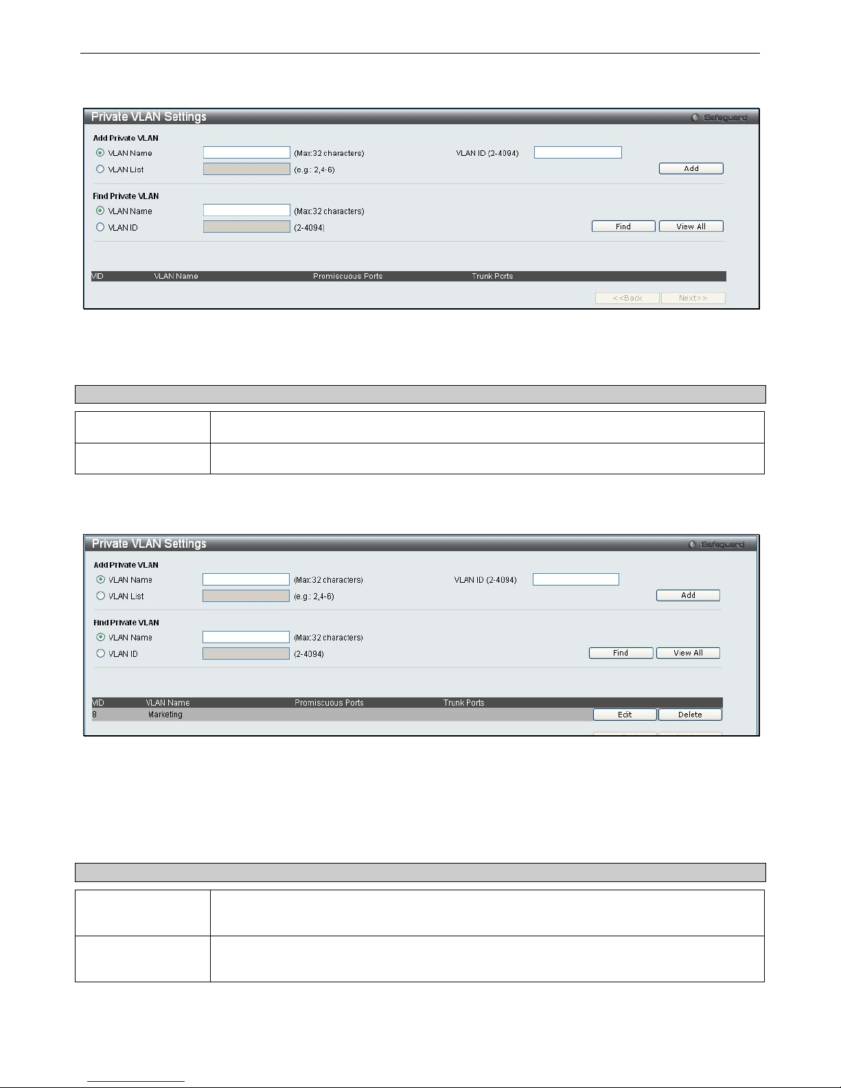
xStack® DGS-3200 Series Layer 2 Gigabit Ethernet Managed Switch
72
To view the following window, click L2 Features > Private VLAN Settings:
Figure 3 - 11. Private VLAN Settings window
Creating a new Private VLAN:
Configure the following parameters in the Add Private VLAN section to create a new Private VLAN:
Parameter Description
VLAN Name
Click the VLAN Name radio button and type the name of the private VLAN.
VLAN ID (2-4094)
If clicking the VLAN Name radio button option, type the VLAN ID of the Private VLAN.
Click
Add
to create the new Private VLAN entry.
The new Private VLAN will appear in the list at the bottom of the window.
Figure 3 - 12. Private VLAN Settings (Edit) window
Searching for an existing Private VLAN:
Configure the following parameters in the Find Private VLAN section to search for an existing Private VLAN:
Parameter Description
VLAN Name
If you want to search for a Private VLAN using the VLAN name, click the VLAN Name radio
button and type the name of the Private VLAN in the adjacent field.
VLAN ID (2-4094)
If clicking the VLAN List radio button option type the VLAN ID of the Private VLAN in the
VLAN ID field.
Click
Find
to search for a Private VLAN.
Page 86
xStack® DGS-3200 Series Layer 2 Gigabit Ethernet Managed Switch
73
If a Private VLAN matches the search criteria, the Private VLAN will appear in the list at the bottom of the window.
The following information is displayed in the Private VLAN list at the bottom of the window:
Parameter Description
VID
Displays the ID of the Private VLAN.
VLAN Name
Displays the name of the Private VLAN.
Promiscuous Ports
Displays the port numbers that have been configured as Promiscuous ports for the Private
VLAN.
Trunk Ports
Displays the port numbers that have been configured as Trunk ports, for the Private VLAN.
Viewing all existing Private VLANs:
Click the
View All
button to display all Private VLAN that have been configured on the Switch.
The Private VLANs will appear in the list at the bottom of the window.
Deleting an existing Private VLAN:
Click the
Delete
button next to the Private VLAN you want to delete from the list at the bottom of the window.
Page 87
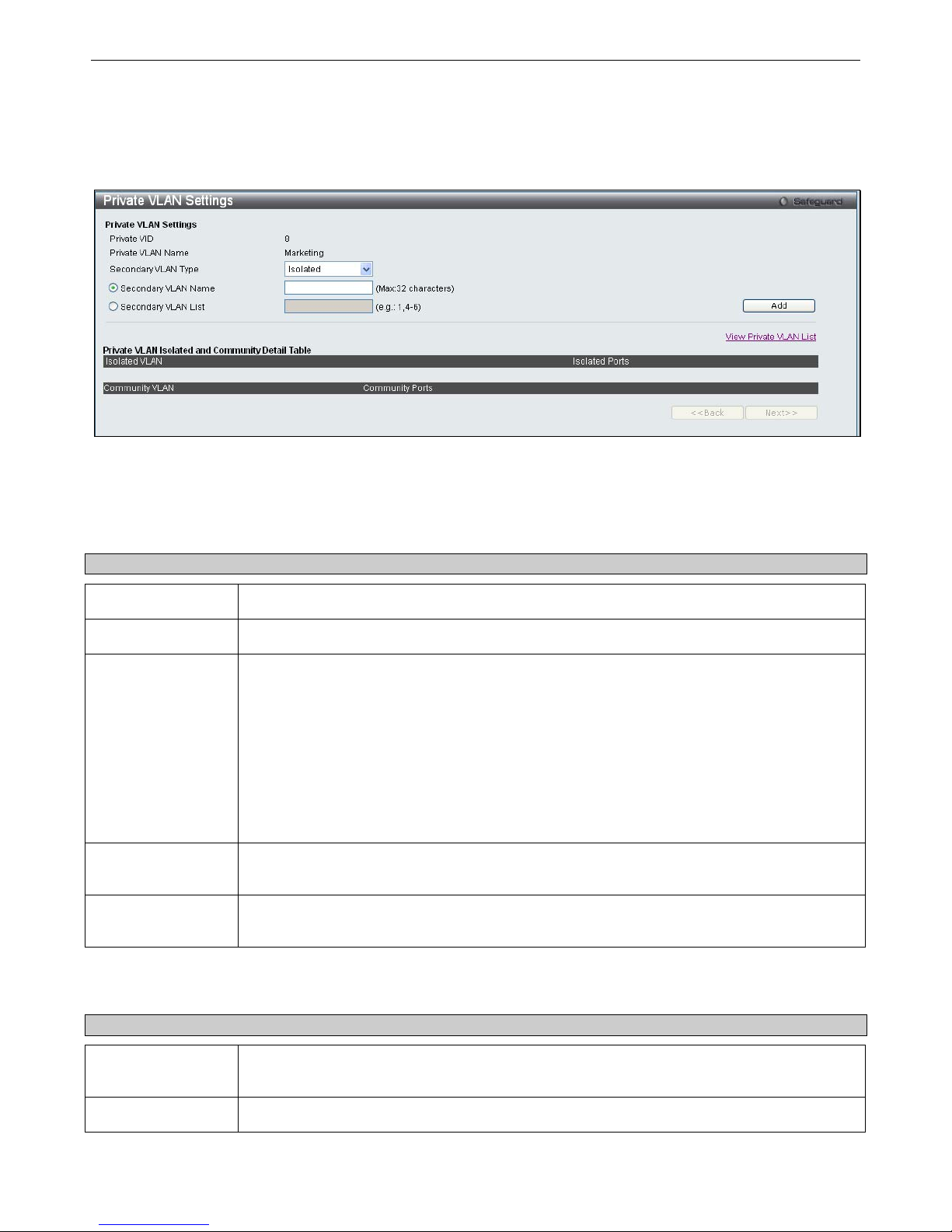
xStack® DGS-3200 Series Layer 2 Gigabit Ethernet Managed Switch
74
Editing an existing Private VLAN:
In the Private VLAN list, click the
Edit
button next to the Private VLAN you want to modify.
The following window opens:
Figure 3 - 13. Private VLAN Settings (Edit) window
The window is divided into two main sections,
Private VLAN Settings
and
Private VLAN Isolated and Community
Detail Table
.
The following parameters are displayed in the
Private VLAN Settings
section:
Parameter Description
Private VID
Displays the VLAN ID of the Private VLAN.
Private VLAN Name
Displays the name of the Private VLAN.
Secondary VLAN
Type
Use the drop-down menu to specify the Secondary VLAN Type. The available options are
described below:
Isolated- An Isolated VLAN is a secondary VLAN whose distinctive characteristic is that all
hosts connected to its ports are isolated at Layer 2. The primary advantage of an isolated
VLAN is that it allows a Private VLAN to only use two VLAN identifiers to provide port isolation
and serve any number of end users. A Private VLAN can only support one isolated VLAN.
Community- A Community VLAN is a secondary VLAN that is associated with a group of ports
that connects to a certain "community" of end devices with mutual trust relationships. There
can be multiple distinct community VLANs in a Private VLAN domain.
Secondary VLAN
Name
Click the Secondary VLAN Name radio button if you want to specify the name of a single
Secondary VLAN. Type the name of the Secondary VLAN in the adjacent field.
Secondary VLAN
List
Click the Secondary VLAN List radio button to specify a range of Secondary VLANs. Type
the VIDs or the range of VIDs that you want to add as Secondary VLANs in the adjacent field.
Click the
Add
button to update the Private VLAN.
The following parameters are displayed in the
Private VLAN Isolated and Community Detail Table
section:
Parameter Description
Isolated VLAN
Displays the VLAN ID or VLAN name of any VLANs that have been configured as Isolated
VLANs.
Isolated Ports
Displays the port numbers of any VLANs that have been configured as Isolated VLANs.
Page 88

xStack® DGS-3200 Series Layer 2 Gigabit Ethernet Managed Switch
75
Community VLAN
Displays the VLAN ID or VLAN name of any VLANs that have been configured as Community
VLANs.
Community Ports
Displays the port numbers of any VLANs that have been configured as Community VLANs.
Deleting a Private Isolated VLAN entry:
Click the
Delete
button next to the Private Isolated VLAN entry you want to delete.
Deleting a Private Community VLAN entry:
Click the
Delete
button next to the Private Community VLAN entry you want to delete.
Page 89
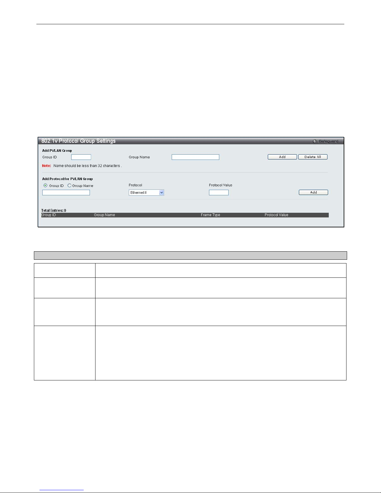
xStack® DGS-3200 Series Layer 2 Gigabit Ethernet Managed Switch
76
802.1v Protocol VLAN
The 802.1v Pro tocol VLAN folder co ntains t wo wi ndows: 802.1v Protocol Gr oup Se ttings and 802.1v Pr otocol VL AN
Settings.
802.1v Protocol Group Settings
Users can c reate Prot ocol VLAN g roups a nd add protocols t o that group. The 8 02.1v P rotocol VLAN Group Set tings s upport
multiple VLANs for each protocol and allows the user to configure the untagged ports of different protocols on the same physical
port. For example, it allows the user to configure an 802.1Q and 802.1v untagged port on the same physical port. The lower half
of the table displays any previously created groups.
To view the following window, click L2 Features > 802.1v Protocol VLAN > 802.1v Protocol Group Settings:
Figure 3 - 14. 802.1v Protocol Group Settings window
The following fields can be set:
Parameter Description
Group ID
Select an ID number for the group, between 1 and 8.
Group Name
This is used to identify the new Protocol VLAN group. Type an alphanumeric string of up to 32
characters.
Protocol
This function maps packets to protocol-defined VLANs by examining the type octet within the
packet header to discover the type of protocol associated with it. Use the drop-down menu to
toggle between Ethernet II, IEEE802.3 LLC, and IEEE802.3 SNAP.
Protocol Value
Enter a value for the Group. The protocol value is used to identify a protocol of the frame type
specified. The form of the input is 0x0 to 0xffff. Depending on the frame type, the octet string
will have one of the following values: For Ethernet II, this is a 16-bit (2-octet) hex value. For
example, IPv4 is 800, IPv6 is 86dd, ARP is 806, etc. For IEEE802.3 SNAP, this is this is a 16bit (2-octet) hex value. For IEEE802.3 LLC, this is the 2-octet IEEE 802.2 Link Service Access
Point (LSAP) pair. The first octet is for Destination Service Access Point (DSAP) and the
second octet is for Source.
Click
Add
to make a new entry and
Delete All
to remove an entry.
Page 90
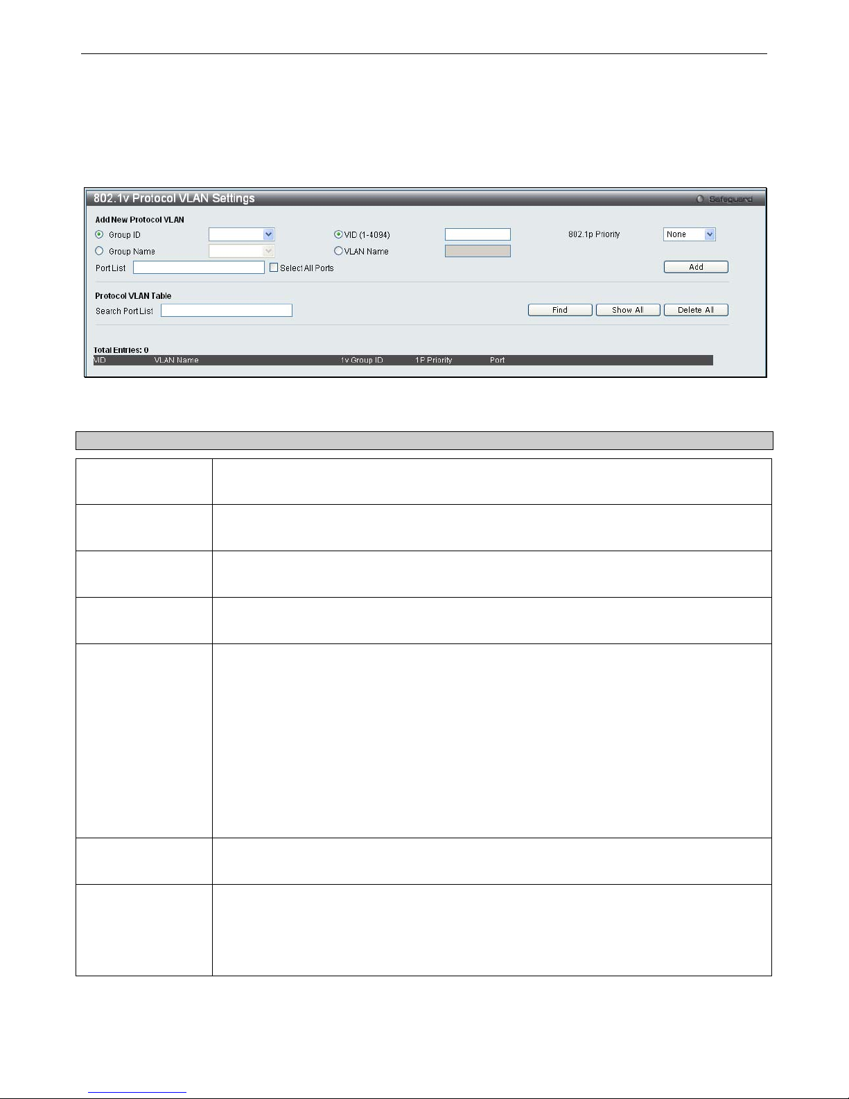
xStack® DGS-3200 Series Layer 2 Gigabit Ethernet Managed Switch
77
802.1v Protocol VLAN Settings
Users can configure Protocol VLAN settings. The lower half of the table displays any previously created settings.
To view the following window, click L2 Features > 802.1v Protocol VLAN > 802.1v Protocol VLAN Settings:
Figure 3 - 15. 802.1v Protocol VLAN Settings window
The following fields can be set:
Parameter Description
Group ID
Highlight the corresponding RADIUS button to select a previously configured Group ID from
the drop-down menu.
Group Name
Highlight the corresponding RADIUS button to select a previously configured Group Name
from the drop-down menu.
VID (1-4094)
Highlight the RADIUS button to enter the VID. This is the VLAN ID that, along with the VLAN
Name, identifies the VLAN the user wishes to create.
VLAN Name
Highlight the RADIUS button to enter a VLAN Name. This is the VLAN Name that, along with
the VLAN ID, identifies the VLAN the user wishes to create.
802.1p Priority
This parameter is specified if you want to re-write the 802.1p default priority previously set in
the Switch, which is used to determine the CoS queue to which packets are forwarded to.
Once this field is specified, packets accepted by the Switch that match this priority are
forwarded to the CoS queue specified previously by the user.
Click the corresponding box if you want to set the 802.1p default priority of a packet to the
value entered in the Priority (0-7) field, which meets the criteria specified previously in this
command, before forwarding it on to the specified CoS queue. Otherwise, a packet will have
its incoming 802.1p user priority re-written to its original value before being forwarded by the
Switch.
For more information on priority queues, CoS queues and mapping for 802.1p, see the QoS
section of this manual.
Port List
Select the specified ports you wish to configure by entering the port number in this field, or tick
the Select All Ports check box.
Search Port List
This function allows the user to search all previously configured port list settings and display
them on the lower half of the table. To search for a port list enter the port number you wish to
view and click Find. To display all previously configured port lists on the bottom half of the
screen click the Show All button, to clear all previously configured lists click the Delete All
button.
Page 91
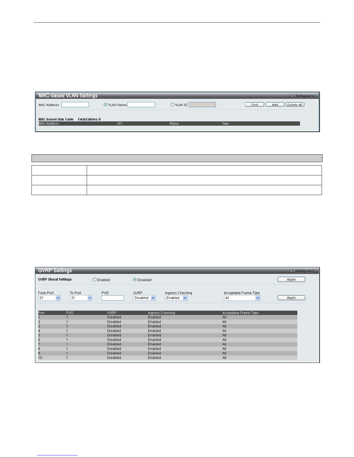
xStack® DGS-3200 Series Layer 2 Gigabit Ethernet Managed Switch
78
MAC-based VLAN Settings
Users can create new MAC-based VLAN entries and search, edit, and delete existing entries. When an entry is created for a port,
the port will automatically become the untagged member port of the specified VLAN. When a static MAC-based VLAN entry is
created for a user, the traffic from this user will be able to be serviced under the specified VLAN regardless of the authentication
function operating on this port.
To view the following window, click L2 Features > MAC-based VLAN Settings:
Figure 3 - 16. MAC-based VLAN Settings window
The following fields can be set:
Parameter Description
MAC Address
Specify the MAC address to be reauthenticated by entering it into the MAC Address field.
VLAN Name
Enter the VLAN name of a previously configured VLAN.
VID
Click this button and enter the VLAN ID.
Click Find, Add or Delete All for changes to take affect.
GVRP Settings
Users can determine wh ether the Switch will sh are its VLAN configuration information with other GARP VLAN Registration
Protocol (GVRP) enabled switches. In addition, Ingress Checking can be used to limit traffic by filtering incoming packets whose
PVID does not match the PVID of the port. Results can be seen in the table under the configuration settings.
To view the following window, click L2 Features > GVRP Settings:
Figure 3 - 17. GVRP Settings window
Click Apply to implement changes made. See table below for description of parameters.
Page 92

xStack® DGS-3200 Series Layer 2 Gigabit Ethernet Managed Switch
79
The following fields can be set:
Parameter Description
From Port
This drop-down menu allows the selection of the beginning port for a range of ports that will be
included in the Port-based VLAN.
To Port
This drop-down menu allows the selection of the ending port for a range of ports that will be
included in the Port-based VLAN.
PVID
This field is used to manually assign a PVID to a VLAN. The Switch's default is to assign all ports
to the default VLAN with a VID of 1.The PVID is used by the port to tag outgoing, untagged
packets, and to make filtering decisions about incoming packets. If the port is specified to accept
only tagged frames - as tagging, and an untagged packet is forwarded to the port for transmission,
the port will add an 802.1Q tag using the PVID to write the VID in the tag. When the packet arrives
at its destination, the receiving device will use the PVID to make VLAN forwarding decisions. If the
port receives a packet, and Ingress filtering is Enabled, the port will compare the VID of the
incoming packet to its PVID. If the two are unequal, the port will drop the packet. If the two are
equal, the port will receive the packet.
GVRP
The GARP VLAN Registration Protocol (GVRP) enables the port to dynamically become a member
of a VLAN. GVRP is Disabled by default.
Ingress Checking
This drop-down menu allows the user to enable the port to compare the VID tag of an incoming
packet with the PVID number assigned to the port. If the two are different, the port filters (drops)
the packet. Disabled disables ingress filtering. Ingress checking is Enabled by default.
Acceptable
Frame Type
This field denotes the type of frame that will be accepted by the port. The user may choose
between Tagged Only, which means only VLAN tagged frames will be accepted, and All, which
mean both tagged and untagged frames will be accepted. All is enabled by default.
PVID Auto Assign Settings
Users can enable or disable PVID Auto Assign Status. The default setting is enabled.
To view the following window, click L2 Features > PVID Auto Assign Settings:
Figure 3 - 18. PVID Auto Assign Settings window
Click Apply to implement changes made. Please see the previous section for more information about PVIDs.
Page 93
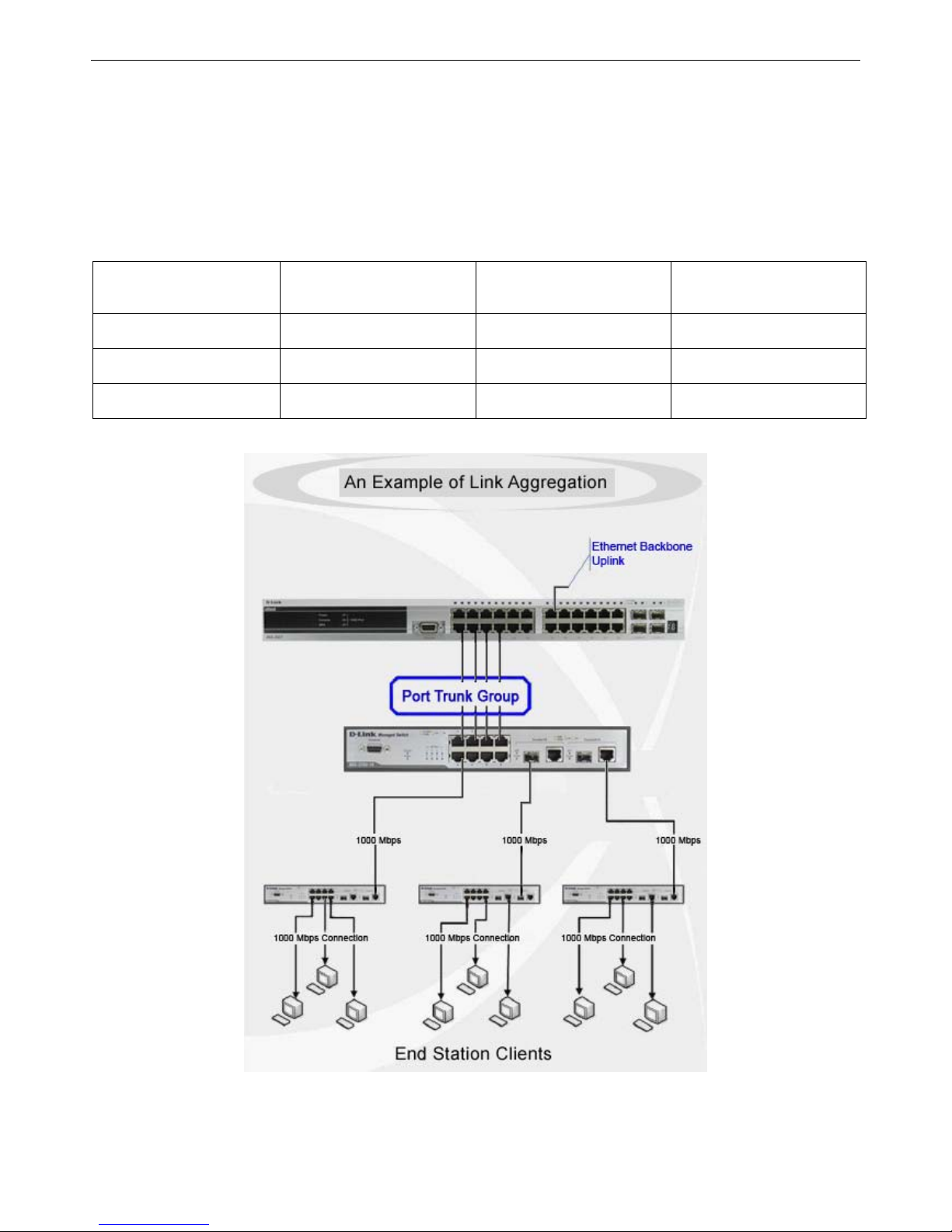
xStack® DGS-3200 Series Layer 2 Gigabit Ethernet Managed Switch
80
Port Trunking
Understanding Port Trunk Groups
Port t runk groups a re u sed t o com bine a num ber o f ports t ogether t o make a si ngle hi gh-band-width data pi peline. Another
advantage of i mplementing port t runk g roups i s redundancy, as i f o ne o f t he ports or l inks fails i n t he port t runk group, t he
network connection to the remote Switch will be maintained. The table below shows the maximum amount of groups supported
for each trunk group and the potential bit rate for the DGS-3200-10, DGS-3200-16, and DGS-3200-24 Switches.
Model Maximum Number of
Groups
Maximum Number of
Ports
Potential Bit Rate
DGS-3200-10
5 8 8000 Mbps
DGS-3200-16
8 8 8000 Mbps
DGS-3200-24
12 8 8000 Mbps
Figure 3 - 19. Port Trunk Group Table for DGS-3200-10/DGS-3200-16/DGS -3200-24
Figure 3 - 20. Example of Typical Port Trunk Group
Page 94
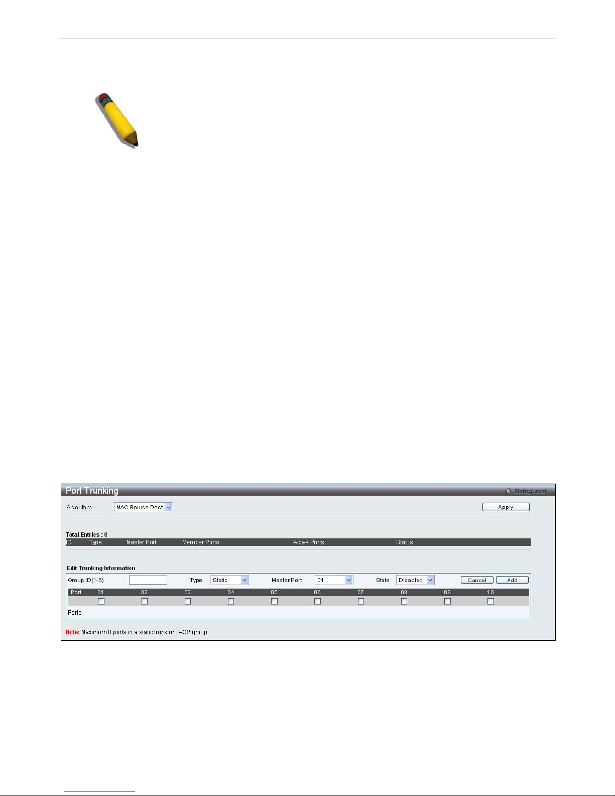
xStack® DGS-3200 Series Layer 2 Gigabit Ethernet Managed Switch
81
The Switch treats all ports in a trunk group as a single port. Data transmitted to a specific host (destination address) will always be
transmitted over the same port in a trunk group. This allows packets in a data stream to arrive in the same order they were sent.
NOTE: If any ports within the trunk group become disconnected, packets intended for
the disconnected port will be load shared among the other linked ports of the link
aggregation group.
Link aggregation allows several ports to be grouped together and to act as a single link. This gives a bandwidth that is a multiple
of a single link's bandwidth.
Link a ggregation i s m ost co mmonly used to l ink a bandwidth i ntensive net work device or devices, suc h as a se rver, t o t he
backbone of a network.
The DGS-3200 Switch series supports the following link aggregation groups:
The DGS-3200-10 model allows the creation of up to five link aggregation groups, each group consisting of 2 to 8 links
(ports).
The DGS-3200-16 model allows the creation of up to eight link aggregation groups, each group consisting of 2 to 8 links
(ports).
The DGS-3200-24 model allows t he creation of up to twelve link a ggregation groups, each group c onsisting of 2 to 8
links (ports).
The (optional) Gigabit ports can only belong to a single link aggregation group. All of the ports in the group must be members of
the sam e VLAN, an d th eir STP stat us, static multicast, traffi c con trol; traffic seg mentation and 80 2.1p defa ult priority
configurations must be i dentical. Port locking, port mirroring a nd 802.1X must not be enabled on the trunk group. Further, the
LACP aggregated links must all be of the same speed and should be configured as full duplex.
The Master Port of the group is to be configured by the user, and all configuration options, including the VLAN configuration that
can be applied to the Master Port, are applied to the entire link aggregation group.
Load b alancing is au tomatically ap plied to th e po rts i n t he ag gregated gr oup, an d a l ink fai lure within t he g roup c auses t he
network traffic to be directed to the remaining links in the group.
The Spanning Tree Protocol will treat a link aggregation group as a single link, on the switch lev el. For STP, the path cost of the
link aggregation group is d etermined by the active port number of the link aggregation group. If t wo redundant link aggregation
groups are configured on the Switch, STP w ill block one entire group; in the same way STP will b lock a sing le port that has a
redundant link.
To view the following window, click L2 Features > Port Trunking:
Figure 3 - 21. Port Trunking window
To configure port trunk groups, click the Add button. To modify an existing port trunk group, click the Edit button corresponding
to the group. To delete a port trunk group, click the corresponding Delete button.
Page 95

xStack® DGS-3200 Series Layer 2 Gigabit Ethernet Managed Switch
82
The user-changeable parameters are as follows:
Parameter Description
Algorithm
Toggle between MAC Source Dest and IP Source Dest.
Group ID
Select an ID number for the group, between 1 and 5 for the DGS-3200-10, between 1 and 8
for the DGS-3200-16, and between 1 and 12 for the DGS-3200-24.
Type
This drop-down menu allows users to select between Static and LACP (Link Aggregation
Control Protocol). LACP allows for the automatic detection of links in a Port Trunking Group.
Master Port
Choose the Master Port for the trunk group using the drop-down menu.
State
Use the drop-down menu to toggle between Enabled and Disabled. This is used to turn a
port trunking group on or off. This is useful for diagnostics, to quickly isolate a bandwidth
intensive network device or to have an absolute backup aggregation group that is not under
automatic control.
Member Ports
Choose the members ports for the trunked group. Up to eight ports per group can be
assigned to a group.
Active Ports
Shows the ports that are currently forwarding packets.
After setting the previous parameters, click Apply to allow your changes to be implemented.
Page 96
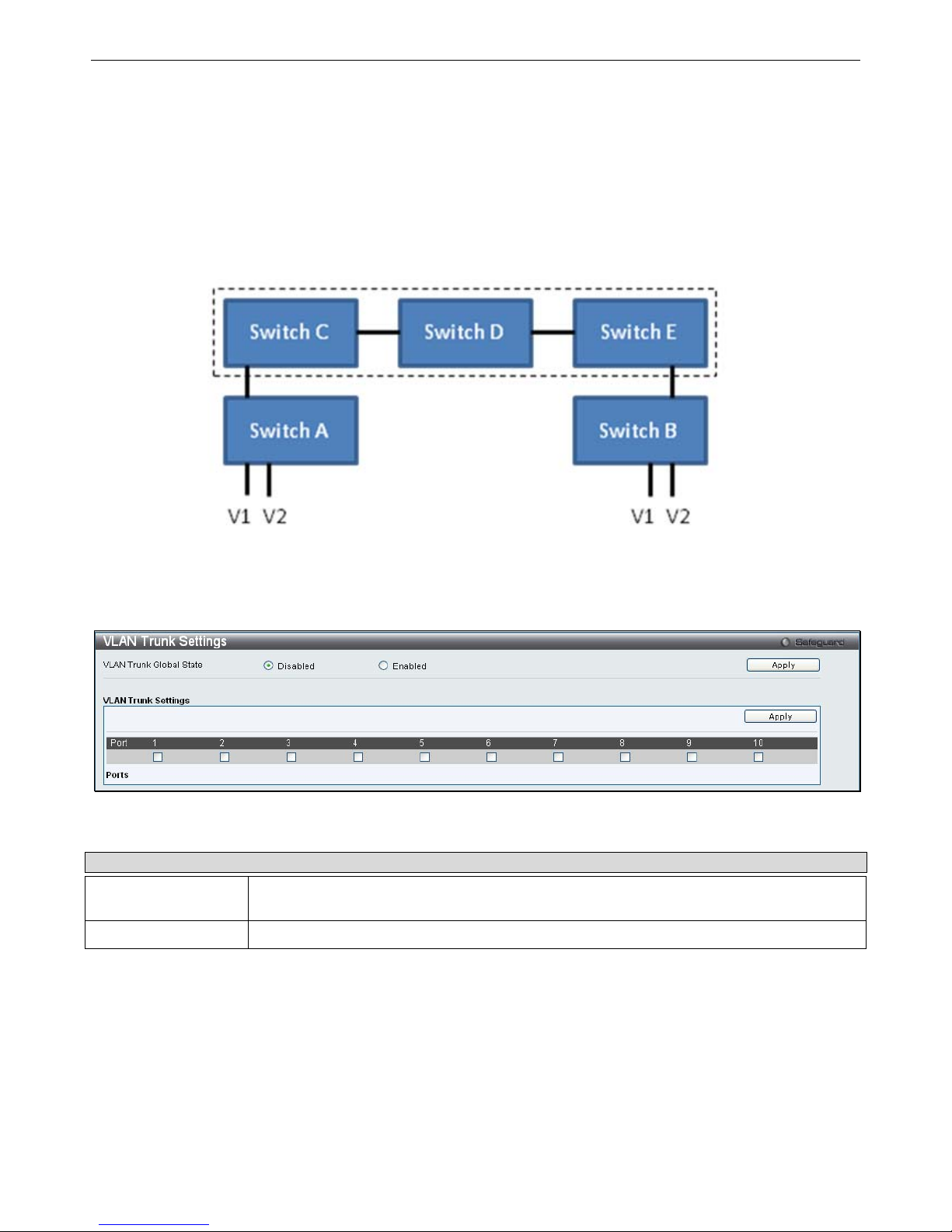
xStack® DGS-3200 Series Layer 2 Gigabit Ethernet Managed Switch
83
VLAN Trunk Settings
Enable VLAN on a port to allow frames belonging to unknown VLAN groups to pass through that port. This is useful if you want
to set up VLAN groups on end devices without having to configure the same VLAN groups on intermediary devices.
Refer to th e following figure fo r an illu strated ex ample. Suppose you want to create VLAN gro ups 1 and 2 (V1 and V2) on
devices A and B. Without a VLAN Trunk, you must first configure VLAN groups 1 and 2 on all intermediary switches C, D and
E; otherwise they will drop frames with un known VLAN group tags. However, with VLAN Trunk enabled on a port(s) in each
intermediary switch, you only need to create VLAN groups in the end devices (A and B). C, D and E automatically allow frames
with VLAN group tags 1 and 2 (VLAN groups that are unknown to those switches) to pass through their VLAN trunking port(s).
Users can combine a number of VLAN ports together to create VLAN trunks. To create VLAN Trunk Port settings on the Switch,
select the ports to be con figured, change the VLAN Trunk Global State to En abled, and click Apply, the new settings will appear
in the VLAN Trunk Settings table in the lower part of the window.
To view the following window, click L2 Features > VLAN Trunk Settings:
Figure 3 - 22. VLAN Trunk Settings window
The user-changeable parameters are as follows:
Parameter Description
VLAN Trunk Global
State
Use the radio buttons to Enable or Disable the VLAN trunking global state.
Ports
The ports to be configured.
Page 97
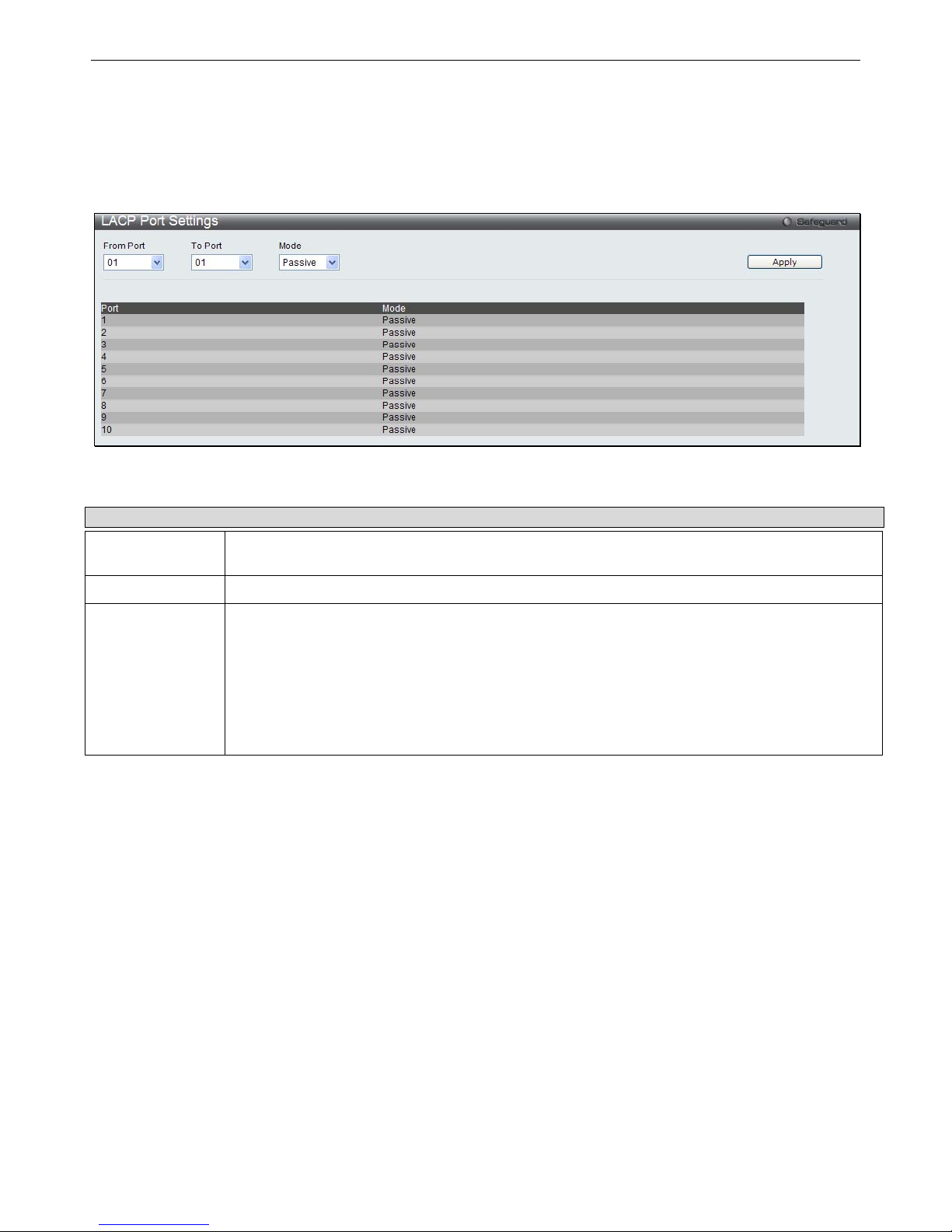
xStack® DGS-3200 Series Layer 2 Gigabit Ethernet Managed Switch
84
LACP Port Settings
In conjunction with the Trunking window, users can create port trunking groups on the Switch. Using the following window, the
user may set which ports will be active and passive in processing and sending LACP control frames.
To view the following window, click L2 Features > LACP Port Settings:
Figure 3 - 23. LACP Port Settings window
The user may set the following parameters:
Parameter Description
From Port
The beginning port of a consecutive group of ports may be configured starting with the selected
port.
To Port
The ending port of a consecutive group of ports may be configured ending with the selected port.
Mode
Active - Active LACP ports are capable of processing and sending LACP control frames. This
allows LACP compliant devices to negotiate the aggregated link so the group may be changed
dynamically as needs require. In order to utilize the ability to change an aggregated port group, that
is, to add or subtract ports from the group, at least one of the participating devices must designate
LACP ports as active. Both devices must support LACP.
Passive - LACP ports that are designated as passive cannot initially send LACP control frames. In
order to allow the linked port group to negotiate adjustments and make changes dynamically, one
end of the connection must have "active" LACP ports (see above).
After setting the previous parameters, click Apply to allow your changes to be implemented.
Page 98
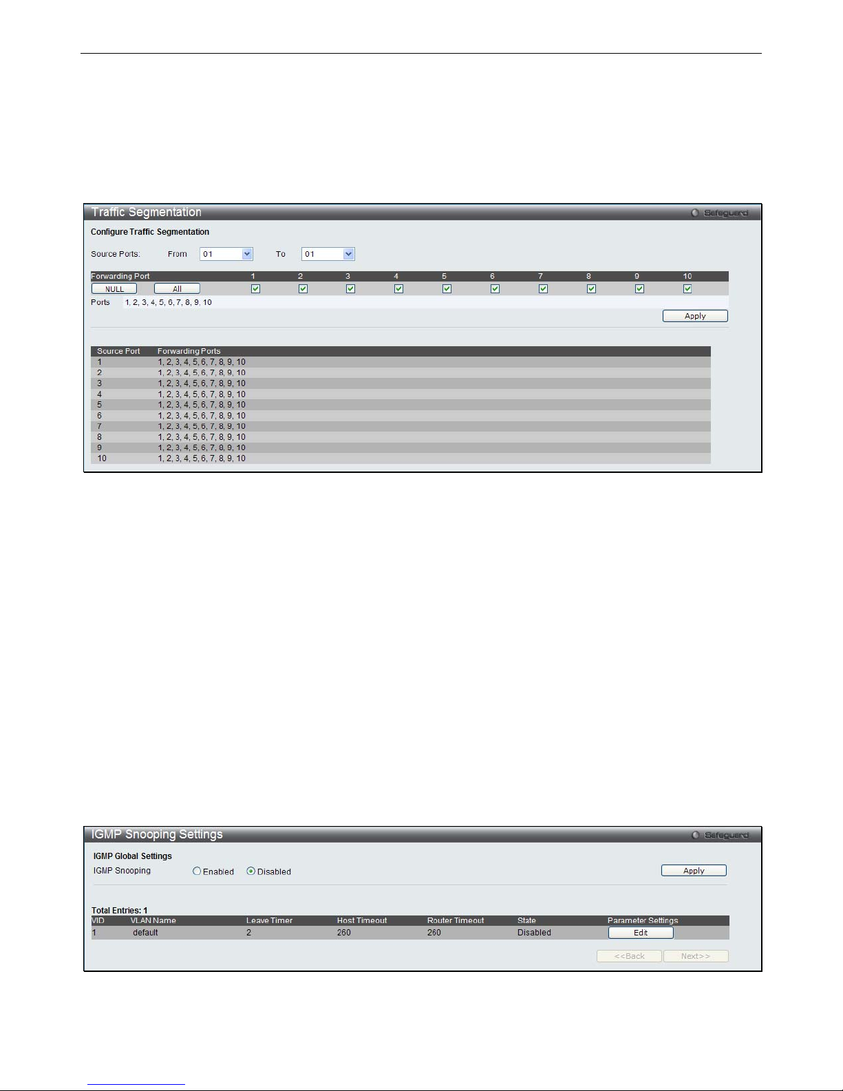
xStack® DGS-3200 Series Layer 2 Gigabit Ethernet Managed Switch
85
Traffic Segmentation
Traffic segmentation is used to limit traffic flow from a single or group of ports, to a group of ports. This method of segmenting
the flow of traffic is similar to using VLANs to limit traffic, but is m ore restrictive. It provides a method of directing traffic that
does not increase the overhead of the Master switch CPU.
To view the following window, click L2 Features > Traffic Segmentation:
Figure 3 - 24. Traffic Segmentation window
To configure traffic segmentation on the Switch, first specify the Source Port(s) using the From and To drop-down menus at the
top of the window. Next, specify which ports on the Switch are able to receive packets from the port(s) specified in the first step.
Clicking the Apply button will enter the combination of transmitting port(s) and allowed receiving ports into the Switch’s Traffic
Segmentation table.
IGMP Snooping
Internet Group Man agement Protocol (IGMP) snooping allows the Switch to recognize IGMP queries and r eports sent between
network st ations or de vices and an I GMP host. When e nabled for IGMP sn ooping, t he Swi tch can open or cl ose a p ort t o a
specific device based on IGMP messages passing through the Switch.
IGMP Snooping Settings
In order to use IGMP Snooping it must first be enabled for the entire Switch under IGMP Global Settings at the top of the window.
You may then fine-tune the settings for each VLAN by clicking the corresponding Edit button. When enabled for IGMP snooping,
the Switch can open or close a port to a specific multicast group member based on IGMP messages sent from the device to the
IGMP host or vice versa. The Switch monitors IGMP messages and discontinues forwarding multicast packets when there are no
longer hosts requesting that they continue.
To view the following window, click L2 Features > IGMP Snooping > IGMP Snooping Settings:
Figure 3 - 25. IGMP Snooping Settings window
Page 99

xStack® DGS-3200 Series Layer 2 Gigabit Ethernet Managed Switch
86
To enable IGMP Snooping globally on the Switch:
Click the Enabled radio button.
Click the Apply button to apply the IGMP Snooping setting.
The following parameters may be viewed in the IGMP Snooping Settings window:
Parameter Description
VID (VLAN ID)
This is the VLAN ID that, along with the VLAN Name, identifies the VLAN the user
wishes to modify the IGMP Snooping Settings for.
VLAN Name
This is the VLAN Name that, along with the VLAN ID, identifies the VLAN the user
wishes to modify the IGMP Snooping Settings for.
Leave Timer
This specifies the maximum amount of time in seconds between the Switch receiving
a leave group message from a host, and the Switch issuing a group membership
query. If no response to the membership query is received before the Leave Timer
expires, the (multicast) forwarding entry for that host is deleted. The default setting is
2 seconds.
Host Timeout
This is the maximum amount of time in seconds allowed for a host to continue
membership in a multicast group without the Switch receiving a host membership
report. Default = 260.
Router Timeout
This is the maximum amount of time in seconds a route is kept in the forwarding
table without receiving a membership report. Default = 260.
State
Select Enabled to implement IGMP Snooping. This field is Disabled by default.
Parameter Settings
Click the Edit button next to the VLAN you want to edit the IGMP Snooping
parameters for.
Page 100

xStack® DGS-3200 Series Layer 2 Gigabit Ethernet Managed Switch
87
Editing the IGMP Snooping parameters for a VLAN:
Click the Edit button next to the VLAN you want to edit.
The following window appears:
Figure 3 - 26. IGMP Snooping Parameters Settings window
The IGMP Snooping Parameters Settings window is divided into two sections. The following parameters can be viewed/modified
in the top half of the window:
Parameter Description
VLAN ID
This is the VLAN ID that, along with the VLAN Name, identifies the VLAN the user
wishes to modify the IGMP Snooping Settings for.
VLAN Name
This is the VLAN Name that, along with the VLAN ID, identifies the VLAN the user
wishes to modify the IGMP Snooping Settings for.
Query Interval (1-65535 sec)
This parameter specifies the length of time between sending IGMP Queries.
Default= 125.
Max Response Time (1-25
sec)
This parameter is used to set the maximum amount of time allowed before sending
an IGMP response report. Default= 10.
Robustness Value (1-255)
This parameter is used as a tuning variable that allows for a large number of packets
being lost on subnetworks. Specify a value between 1 and 255. Specify a high value
if you expect your subnetworks to lose a large number of packets. Default= 2.
Last Member Query Interval
(1-25 Sec)
This parameter is used to set the maximum amount of time between group-specific
query messages, including messages that have been sent in response to leave
group messages. Default= 2.
Host Timeout (1-16711450
sec)
This is the maximum amount of time in seconds allowed for a host to continue
membership in a multicast group without the Switch receiving a host membership
report. Default = 260.
 Loading...