

Page 1

Manual
Building Networks for People
D-Link DG-102SP
VoIP Station Gateway
Version 1.10
Page 2

2
Content s
Package Contents ................................................................................3
Introduction............................................................................................4
Features and Benefits ...........................................................................5
Getting S tarted ......................................................................................6
Configuration ......................................................................................10
Using Web-Based Management .........................................................11
Configuration Using a Console............................................................37
Using the Boot Menu ...........................................................................48
Command Line Interface .....................................................................56
T echnical S pecifications ......................................................................64
Warranty..............................................................................................67
Registration ........................................................................................70
Contacting T echnical Support ..............................................................71
Page 3
3
Package Content s
System Requirements:
Contents of Package:
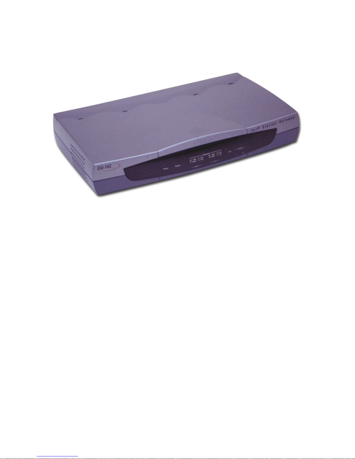
D-Link DG-102SP VoIP Station Gateway
Ethernet Cable (Straight-through CAT5 with RJ-45 connectors)
12V/1A A/C Power Adapter
If any of the above items are missing, please contact your reseller.
Internet Explorer V ersion 6.0 or Netscape Navigator
V ersion 6.0 and Above
Computers with Windows, Macintosh, or Linux-based
operating systems with an installed Ethernet adapter
Page 4

4
Introduction
The D-Link DG-102SP V oIP S tation Gateway links traditional telephony networks
to IP networks with conventional telephony devices such as analog phones or
fax machines. The DG-102SP includes two loop start Foreign Exchange
Subscriber (FXS) that interfaces with normal RJ-11 telephone connectors to
provide voice/fax communication over the IP network. The DG-102SP also
includes two 10/100 Mbps Fast Ethernet ports. One Ethernet port is for a DSL/
Cable Modem or other WAN devices, and the other may function as a connection
to create a home or small office LAN network. Enabling Nat on the DG-102SP
will allow multiple clients to connect to the Internet. It can be configured and
monitored via the Console, Web browser, or Telnet and also supports SNMP
management.
By routing calls over the Internet or any IP network, this gateway can reduce or
eliminate long distance or inter-office phone charges. Corporations can also
enjoy the benefits of network consolidation and the reduction of leased lines by
relying on Internet service providers to deliver toll-quality voice communications
over the IP networks.
Page 5

5
Features and Benefits
Designed for versatility and performance, the DG-102SP V oIP Gateway provides
the following features:
**
One 10/100 Fast Ethernet WAN port for connecting to a call agent
One analog POTS interface for PSTN Life Line
Two analog loop-start FXS interfaces using female RJ-11 connectors
One 10/100 Fast Ethernet LAN port for connecting to a local network
IP address assignment using DHCP (Dynamic Host Configuration
Protocol) or static configuration
Silence suppression to reduce bandwidth consumption
Comfort noise generation for a more natural feel
Adaptive jitter buffer for smooth voice reception
Lost packet recovery ability for improved voice quality
Command port for easy configuration
Remote Software download/update
IP sharing support to allow multiple users access to the Internet via
a single IP address
Built-in PPPoE function to support dial-up connection for broadband
technology
Caller ID
QoS ensure to guarantee voice quality
Life Line support
1. Automatic fall back to PSTN in case of power failure or network
breakdown
2. Intelligent dialing mode (IP/PSTN Call) alternation via configurable
hot key (“ # “ key is the default)
3. Listening of incoming calls from PSTN
Page 6
6
Getting Started
Identifying External Components
Front Panel
Understanding Indicators
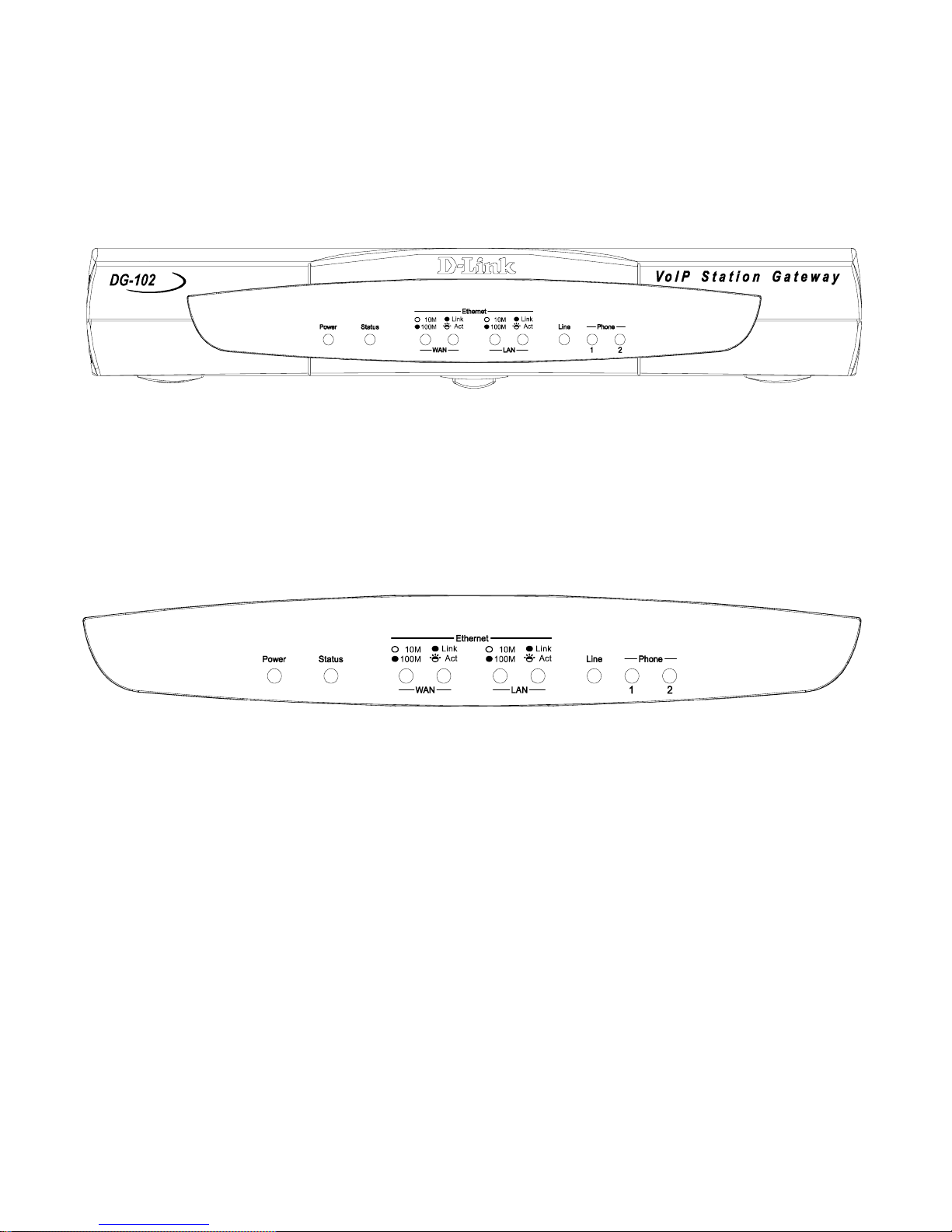
Before configuring your VoIP Gateway, take a few minutes to look over this
section and familiarize yourself with the front panel LED indicators depicted
below.
Power: This LED is lit when the device is receiving power; otherwise, it
is unlit.
Status: This LED will flash quickly when the DG-102SP is either performing a self test or booting up. The LED will remain lit when the system
is ready for a connection with the call agent. It will remain dark when the
system is ready but can not receive an acknowledgement from the SIP
server.
WAN: This LED displays the connection speed, link status, and activity
on the 10/100 dual-speed Ethernet port that is used to connect to your
WAN device (usually a DSL/cable modem).
Page 7
7
Getting Started
Identifying External Components
10/100M: This indicator remains unlit when there is no connection, or
the port is operating at 10Mbps through a connection to a 10BASE-T
device. It is lit when the port is operating at 100Mbps through a connection to a dual-speed or 100BASE-TX Fast Ethernet device.
Link/Act: When a good link to a powered-up, but idle device is detected on a port, this indicator shines steadily. When packets are received from the device, the indicator blinks.
Rear Panel
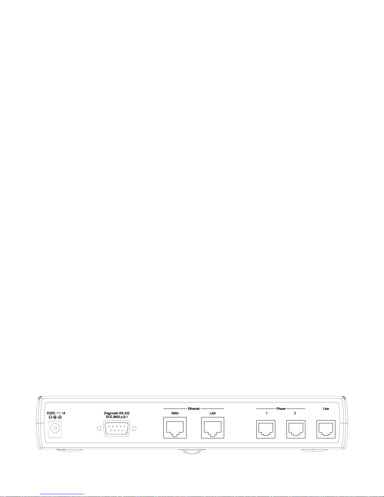
Line: Lights when PSTN line is in use.
Phone 1 to 2: Lights when standard phone port is in use.
Note: If a powered-up device is connected to a port and the port’s Link/Act status
indicator is unlit, the most probable cause is a cabling or connection problem
(for example, wrong cable type or bad contact) or a device malfunction.
LAN: This LED displays the connection speed, link status, and activity on
the 10/100 dual-speed Ethernet port that is used to connect to your LAN.
10/100M: This indicator remains unlit when there is no connection, or
the port is operating at 10Mbps through a connection to a 10BASE-T
device. It is lit when the port is operating at 100Mbps through a connection to a dual-speed or 100BASE-TX Fast Ethernet device.
Link/Act: When a good link to a powered-up, but idle device is detected on a port, this indicator shines steadily. When packets are received from the device, the indicator blinks.
Page 8

8
Getting Started
Identifying External Components
Fast Ethernet LAN: A 10/100 dual-speed Ethernet port fitted with an
RJ-45 connector used to connect the VoIP gateway to a LAN device
(switch, PC, etc.). This port accepts Category 5 or higher UTP cabling
with an RJ-45 connector.
Line: RJ-1 1 phone jack for connecting to a standard telephone wall outlet through an approved (No. 26 A WG or larger) telecommunications line
cord.
Phone 1 to 2: Normal RJ-11 phone jacks used to connect analog (or
digital) telephones and fax machines. Plug your telephone(s) and/or fax
machine directly into any of these jacks.
Installation
When choosing a place to install the VoIP Gateway, please use the following
guidelines:
The power outlet should be within 1.82 meters (6 feet) of the device.
Visually inspect the power cord and see that it is secured to the AC
power connector.
AC Power Connector: For the included power adapter. Be sure to use
only the 12V1/A power adapter included with the product. Using the wrong
power adapter can damage the product and void the warranty.
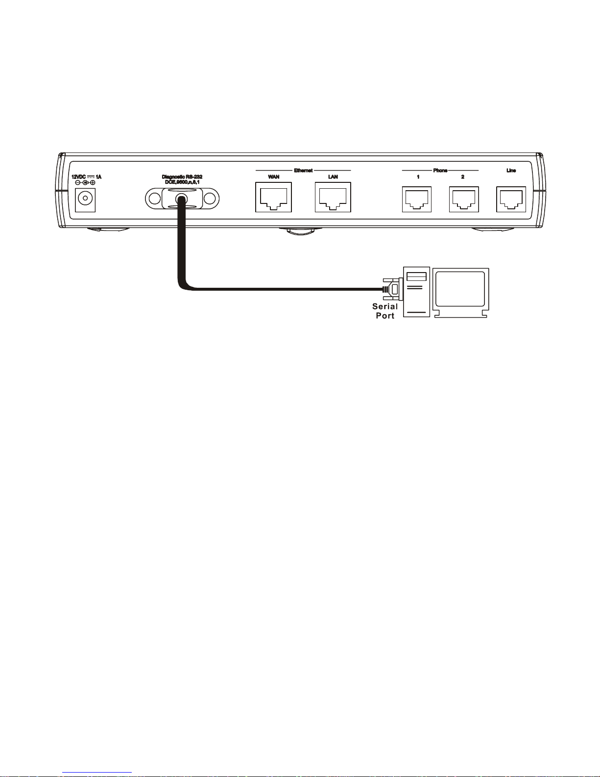
Diagnostic Port: An RS-232 serial port used to configure the device.
Plug one end of a straight-through wired RS-232 cable to the device and
the other end to a serial port of a PC running a terminal emulation program (such as Microsoft HyperTerminal) or a VT-100 terminal.
Fast Ethernet WAN: A 10/100 dual-speed Ethernet port fitted with an RJ45 connector used to connect the V oIP gateway to a WAN device (usually
a router). This port accepts Category 3, 4 or 5 UTP cabling with an RJ-45
connector.
Page 9
9
Getting Started
Installation
Connecting the Network Cable
Category 3, 4 or 5 UTP cable can be used to make the Ethernet connection to
your router.
Connecting the VoIP Gateway to a Hub/Switch
Connecting the VoIP Gateway to a Computer
The DG-102SP requires a straight-through cable when connecting to a
computer . make sure that your IP address on your Ethernet card is in the same
subnet as the DG-102SP otherwise it will not connect
To connect the device to either a hub or switch, you must connect the straightthrough cable to the LAN port.
When installing the unit on a desktop or shelf, the rubber feet included with the device should be attached. These cushioning feet
should be attached to the bottom corners of the device.
Do not place heavy objects on the DG-102SP at any time. Placing
the DG-102SP in a well ventilated area is very important. Not doing
so may cause damage to the unit.
Page 10

10
Configuration
Configuring the VoIP Gateway
Using a web browser on a computer connected to the device via the
WAN or LAN Ethernet connections. In the discussion below , the computer
running the browser is referred to as the management station.
Using a terminal or computer running terminal emulation software
connected to the diagnostic port via an RS-232 cable. In the discussion
below, the terminal (or computer) is referred to as a console and the
connection, a console connection.
There are two ways to configure the V oIP gateway:
Page 11
11
The categories listed on the left-side of the web-based management module
include:
Using Web-Based Management
The DG-102SP V oIP Gateway of fers an embedded W eb-based (hypertext) interface allowing users to manage the device from anywhere on the network
through a standard browser such as Netscape Navigator , 6.x or later , or Microsoft
Internet Explorer , 6.x or later . The Web browser act s as a universal access tool
and can communicate directly with the device using HTTP protocol. Your
browser screen may vary with the screen shots (pictures) in this guide.
Note: This Web-based Management Module does not accept Chinese language
input (or other languages requiring two bytes per character).
The first step in getting started in using Web based management for your device
is to secure a browser. A Web browser is a program that allows a person to
read hypertext, for example, Netscape Navigator , 6.x or later , or Microsoft Internet
Explorer , 6.x or later. Follow the installation instructions for the browser .
The second and last step is to configure the IP interface of the device. This can
be done manually through a console. See the Configuring the VoIP Gateway
using a Web Browser section of the “Configuration” section for specific
instructions.
Management
To begin managing your device simply run the browser you have installed on
your computer and point it to the IP address you have defined for the device.
The URL in the address bar should read similar to: http://123.123.123.123, where
the numbers 123 represent the IP address of the device.
In the page that opens, click on the following Login to the web-based
management module button:
Config IP (Config Device IP Address)
Device Information
T elephony Configuration
SIP Configuration (Server , User Agent and Peer to Peer)
DHCP Configuration (Dynamic IP Assignment and S tatic IP Assignment)
Page 12
12
Using Web-Based Management
Management
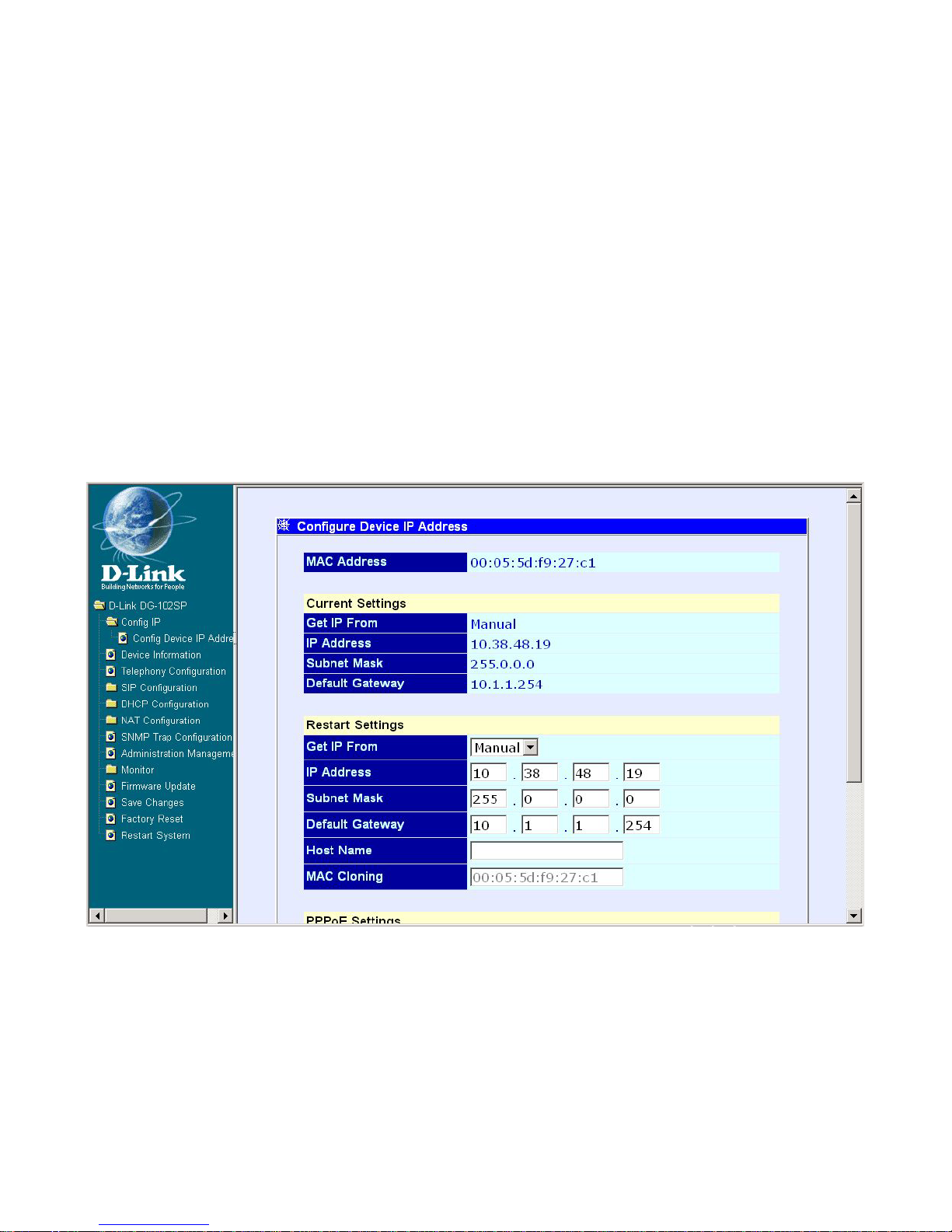
Configure Device IP Address
The items on this window are described below:
Restart Settings
Get IP From: Select the method the V oIP gateway will use to obtain it s IP
settings once it is rebooted. Choices include:
Manual: When Manual is selected, the VoIP gateway will obtain its IP
settings from the fields located just below.
Configure Device IP Address window
Restart System.
NA T Configuration (NA T Configuration and Local Server Configuration)
SNMP Trap Configuration, Administration Management
Monitor (Ethernet S tatistics, DSP Statistics, Tcid Configuration, and Cod-
ing Profile)
Firmware and Configuration Update
Save Changes
Factory Reset
Page 13
13
BOOTP: When BOOTP is selected, the VoIP will attempt to obtain its
IP settings from a BOOTP server located on your LAN.
DHCP: When DHCP is selected, the VoIP will attempt to obtain its IP
settings from a DCHP server located on your LAN.
IP Address: Enter an IP address for the VoIP gateway .
Subnet Mask: Enter a subnet mask for the VoIP gateway.
Default Gateway: Enter the IP address of the WAN device (usually a
router) you are using to make the WAN connection.
Host Name: This is a user-defined host name for this V oIP Gateway.
MAC Cloning: Enter the MAC address for MAC Cloning. (This function is not
supported on this version)
PPPoE Settings (for DSL users)
State: Enables or disables the PPPoE function.
User Name: Enter the User Name for the PPPoE function.
Password: Enter the Password for the PPPoE function.
Using Web-Based Management
Management
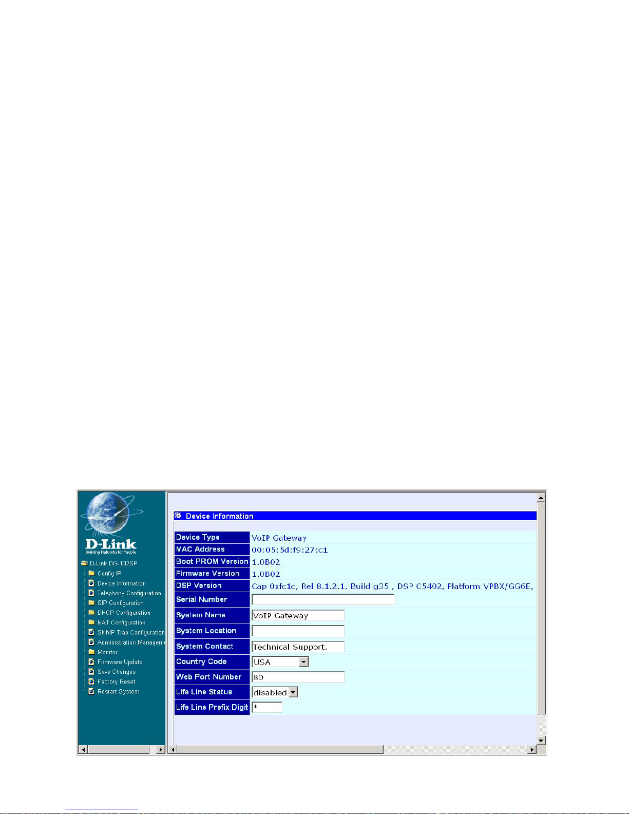
Device Information
Device Information window
Page 14

14
The items on this window are described below:
Using Web-Based Management
Device Information
Device Type: This displays the model name of this device.
MAC Address: This displays the MAC address of this device.
Boot PROM Version: This displays the version number of the device’s
startup code.
Firmware Version: This displays the version number of the device’s
runtime code.
DSP Version: This displays the Digital Signal Processor version, if any.
Serial Number: This field is for a user-determined identification number .
System Name: This is a user-defined name for this device.
System Location: This is a user-defined physical location of the device.
System Contact: This is user-defined contact information for the person
or department responsible for the maintenance of this device.
Country Code: This is a user-defined country code for this device.
<0:USA (Default), 1:Japan, 2:Hong Kong, 3:Sweden, 4:China>
Web Port Number: This is a user-defined web port number.
Life Line Status: Enables or disables the Lifeline function.
Life Line Prefix Digit: This is a user-defined Lifeline prefixed key for this
device (Default is “#” key).
Click on the Save button at the bottom right of the window to save the settings.
Page 15
15
Using Web-Based Management
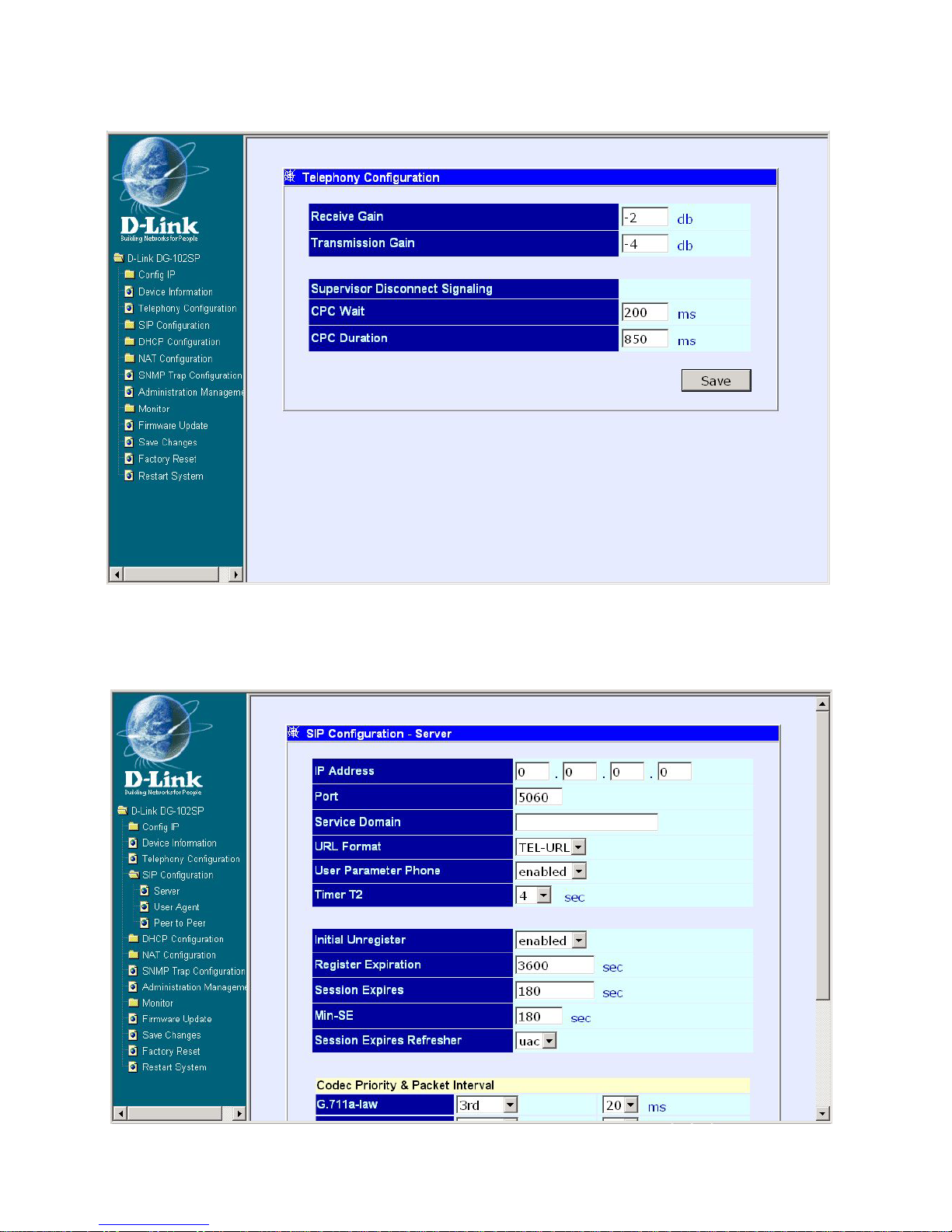
Telephony Configuration
Telephony Configuration window
Enter the desired information on the window above and then click Save.
SIP Configuration - Server
SIP Configuration window
Page 16

16
Using Web-Based Management
SIP Configuration - Server
The items on this window are described below:
IP Address: Enter the IP address of SIP server.
Port: Enter the port number of SIP server (Default is 5060).
Service Domain: This is a user-defined service domain for SIP server.
URL Format: This is a user-defined URL format for SIP server.
User Parameter: This is used to enable or disable the function of attach
“user=phone” parameter in SIP-URL or not.
Timer T2: This is user-defined T2 timer of SIP protocol. (Range: 4, 8, 16,
32 sec)
Initial Unregister: Enable or disable the initial unregistered function.
Register Expiration: Enter the timer of register expiration.
Session Expires: Enter the timer of Expires.
Min-SE: Enter the timer of Min-SE.
Session Expires Refresher: Choose the session expires refresher: uac
or uas.
Click on the Save button at the bottom right of the screen to save the settings.
Page 17
17
Using Web-Based Management
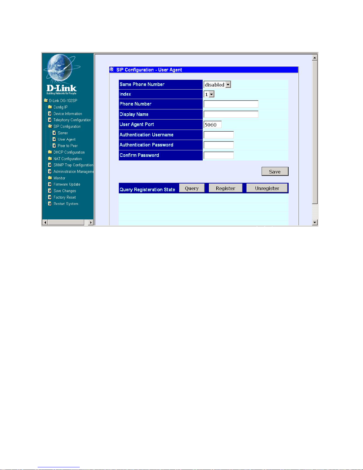
SIP Configuration - User Agent
SIP Configuration – User Agent window
The items on this window are described below:
Click on the Save button at the bottom right of the screen to save the settings.
Same Phone Number: Enable or disable the same phone number
function.
Index: Choose the Phone 1 or Phone 2.
Phone Number: This is a user-defined phone number for each phone
port.
Display Name: This is a user-defined display name for each phone port.
User Agent Port: This is a user-defined unique port number for each
phone port.
Authentication Username: Enter the Username for SIP server
authentication.
Authentication Password: Enter the Password for SIP server
authentication.
Confirm Password: Enter the Password again for confirmation.
Page 18

18
Using Web-Based Management
SIP Configuration - Peer to Peer
SIP Configuration – Peer to Peer window
This window displays the Peer to Peer setting for non-SIP server mode. It lists
the ten numbers, which support Peer to Peer communication.
Click one of the ten pointer icons to access and edit the second SIP
Configuration-Peer to Peer window:
Page 19
19
Using Web-Based Management
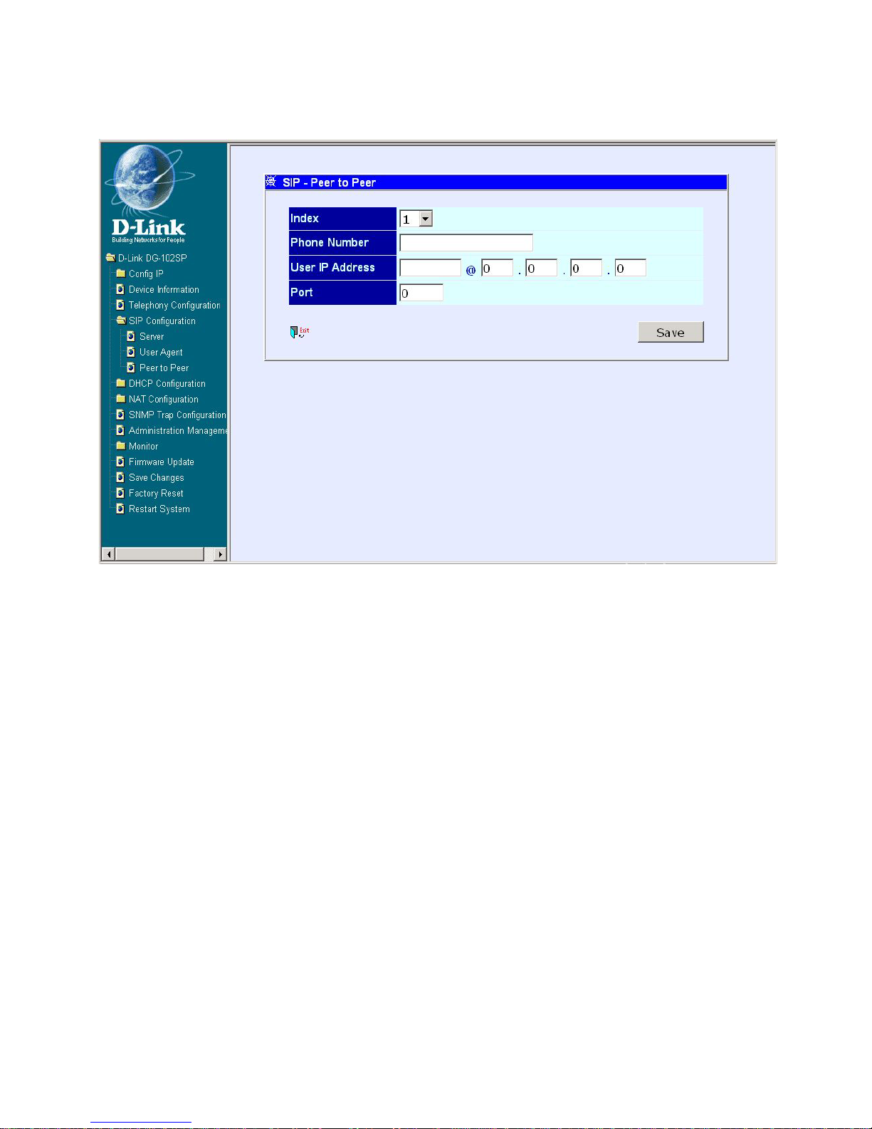
The items on this window are described below:
Index: Choose the index number that you would like to edit (Form 1 to
10).
Phone Number: This is a user-defined dialing phone number of the
destination endpoint.
User IP Address: Enter the phone number and IP address of the
destination endpoint. (Format: <Destination Phone
number>@<Destination IP Address X.X.X.X>)
Port: Enter the port number of the destination endpoint.
Click on the Save button at the bottom right of the screen to save the settings.
SIP Configuration - Peer to Peer
Second SIP Configuration – Peer to Peer window
Page 20
20
Using Web-Based Management
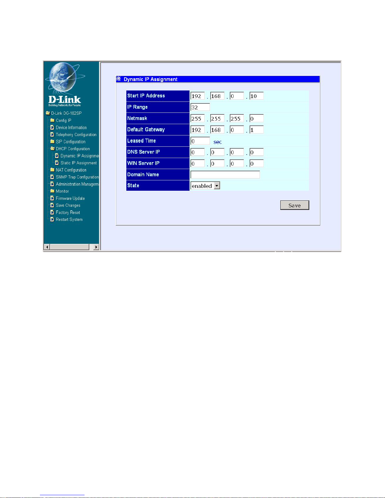
Dynamic IP Assignment
Dynamic IP Assignment window
Use the Dynamic IP Assignment to configure the device to act as a DHCP
server for the LAN.
The items on this window are described below:
Start IP Address: This is the base (starting) address for the IP pool of
unassigned IP addresses.
IP Range: This is the range of contiguous, IP addresses above the base
IP Address.
Netmask: This mask informs the client how the destination IP address is
to be divided into network, subnet, and host parts. The netmask has ones
in the bit positions in the 32-bit address which are to be used for the
network and subnet parts, and zeros for the host part.
Default Gateway: This specifies the Gateway IP Address that will be
assigned to and used by the DHCP clients.
Page 21
21
Using Web-Based Management
Dynamic IP Assignment
Leased Time: This specifies the amount of time (in hours) a client can
lease an IP address from the dynamically allocated IP pool.
DNS Server IP: This specifies the Domain Name System server, used
by the DHCP clients using leased IP addresses, to translate hostnames
into IP addresses or vice-versa.
WIN Server IP: Some LANs may require using WINS servers. You may
enter the IP address of the WINS server or leave the field blank.
Domain Name: You may enter a domain name for the network group or
leave the field blank.
State: This toggles Disable and Enable for DHCP function.
Click on the Save button at the bottom right of the window to save the settings.
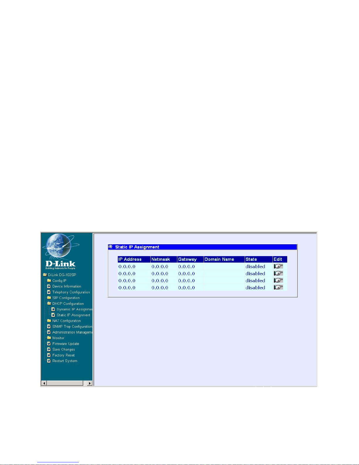
DHCP Configuration - Static IP Assignment
First Static IP Assignment window
Page 22
22
Using Web Based Management
DHCP Configuration - S tatic IP Assignment
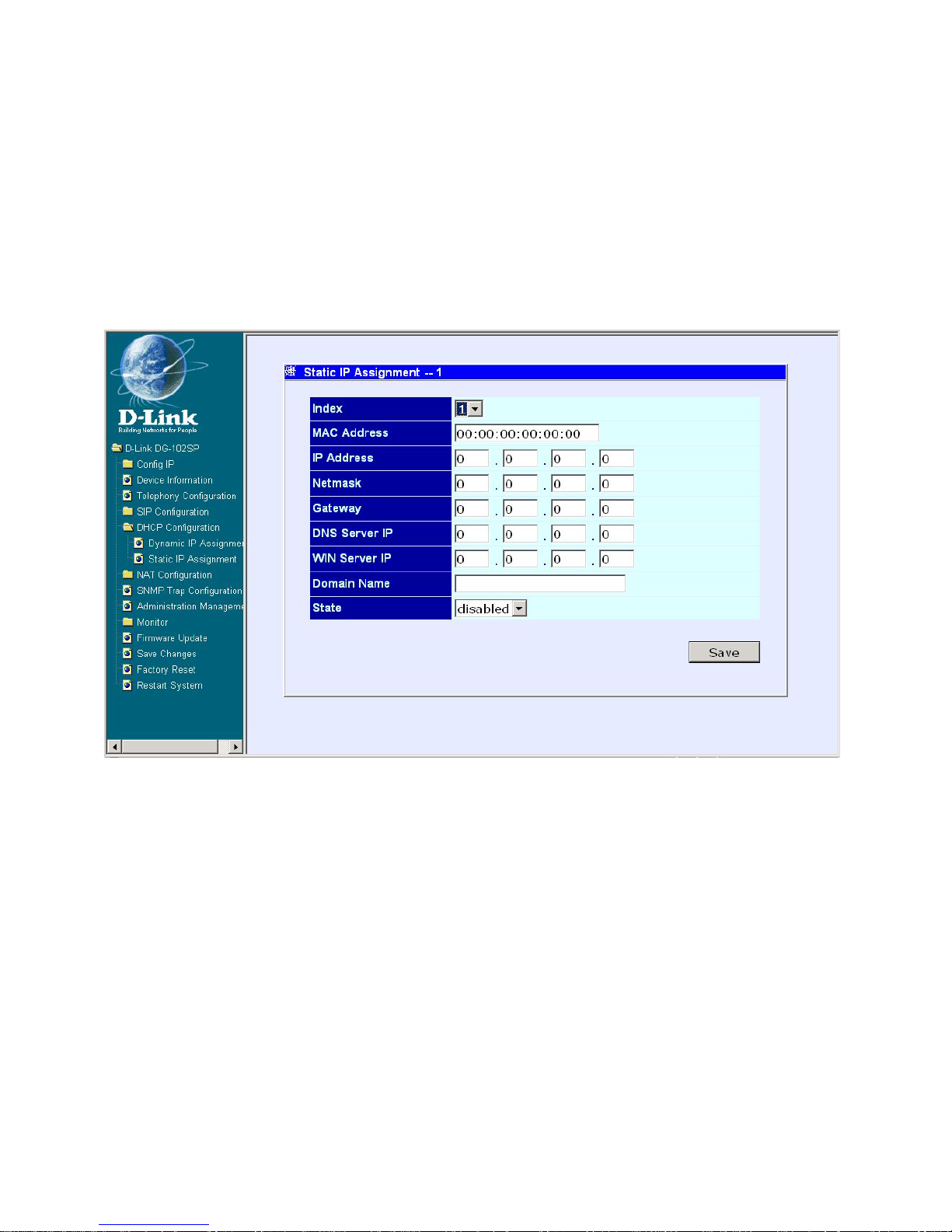
The Static IP Assignment functions in the same way as the Dynamic IP Assignment. The only difference is that a particular IP address can be assigned
to a particular host. The host is identified by the MAC Address of its NIC which
must be entered on the next screen.
Click the Edit icon on the window above to access the second Static IP As-
signment window:
Second Static IP Assignment window
The items on this window are described below:
Index: Choose the index number that you would like to edit (From 1 to 4).
MAC Address: This specifies the physical address of the particular host
that will receive the assigned IP address.
IP Address: This is the static IP address to be assigned.
All other parameters (Netmask, Gateway, DNS Server IP, WINS Server IP,
Domain Name, and S tate) are identical to those in the Dynamic IP Assignment
in the previous section.
Click on the Save button at the bottom right of the window to save the settings.
Page 23
23
Using Web-Based Management
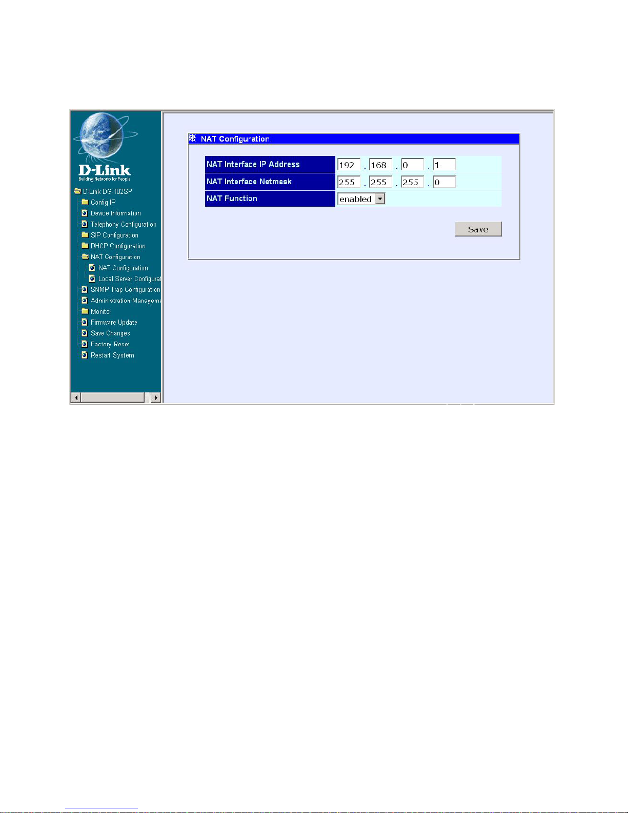
NAT Configuration
NAT Configuration window
After entering the desired information into the window above, enable or disable
the NAT Function and then click Save.
Page 24
24
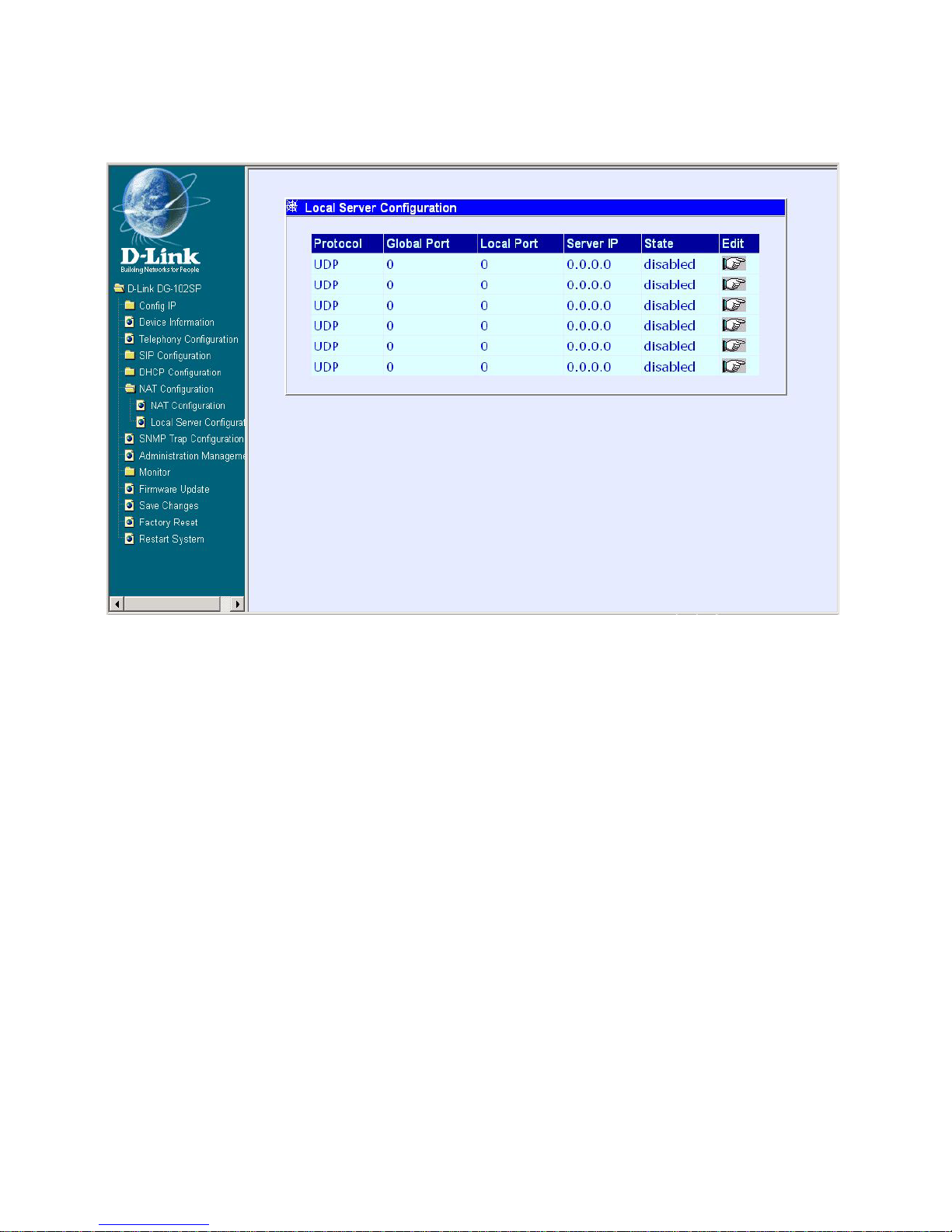
Local Server Configuration
Using Web-Based Management
This window allows you to view the current local server configuration settings.
Click the Edit icon on the window above to access the second Local Server
Configuration window:
First Local Server Configuration window
Page 25
25
Using Web-Based Management
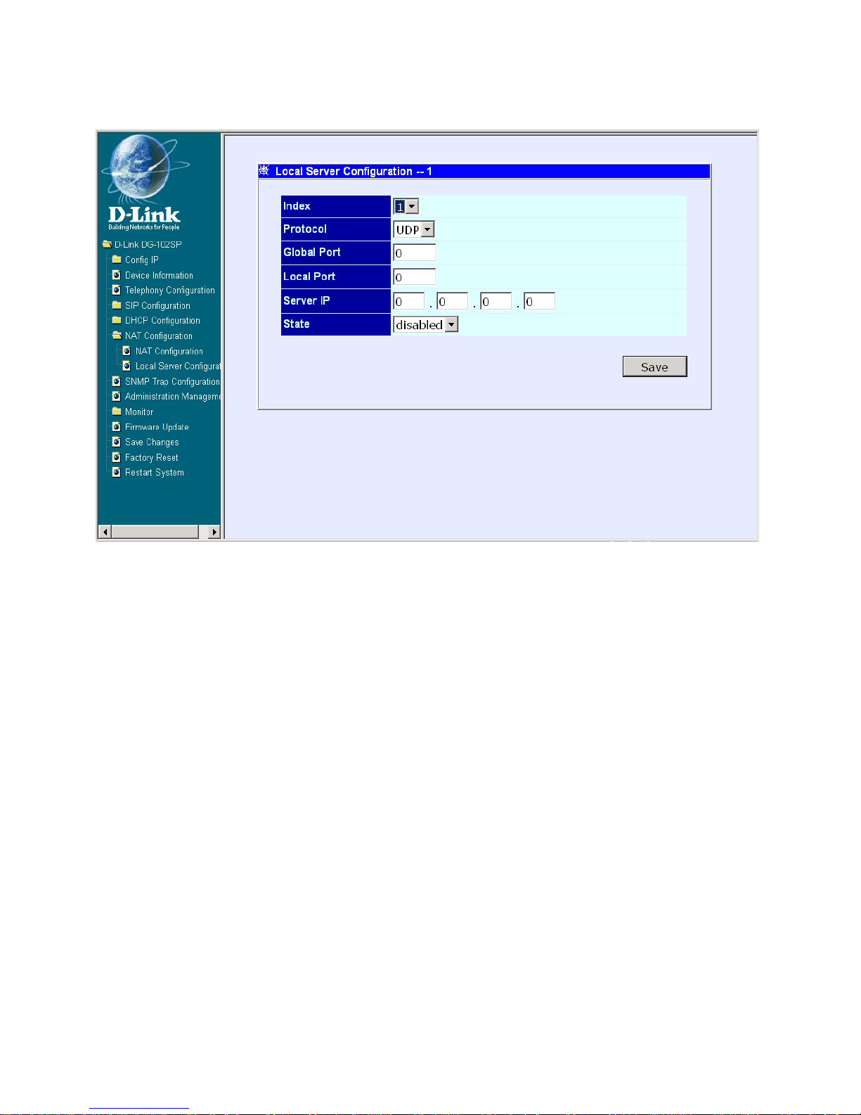
Local Server Configuration
Second Local Server Configuration Window
The items on this window are described below:
Index: Choose the index number that you would like to edit (From 1 to 6).
Protocol: Choose either the TCP or UDP protocol.
Global Port: Enter the designated TCP or UDP protocol port number for
the particular protocol packet you wish to redirect.
Local Port: Enter the port number used by the designated host on the
LAN or use a well-known port.
Server IP: Enter the IP address of the local designated host computer
or device.
State: This toggles Disable and Enable for the Local Server Configuration
function.
Click on the Save button at the bottom right of the window to save the settings.
Page 26
26
Using Web-Based Management
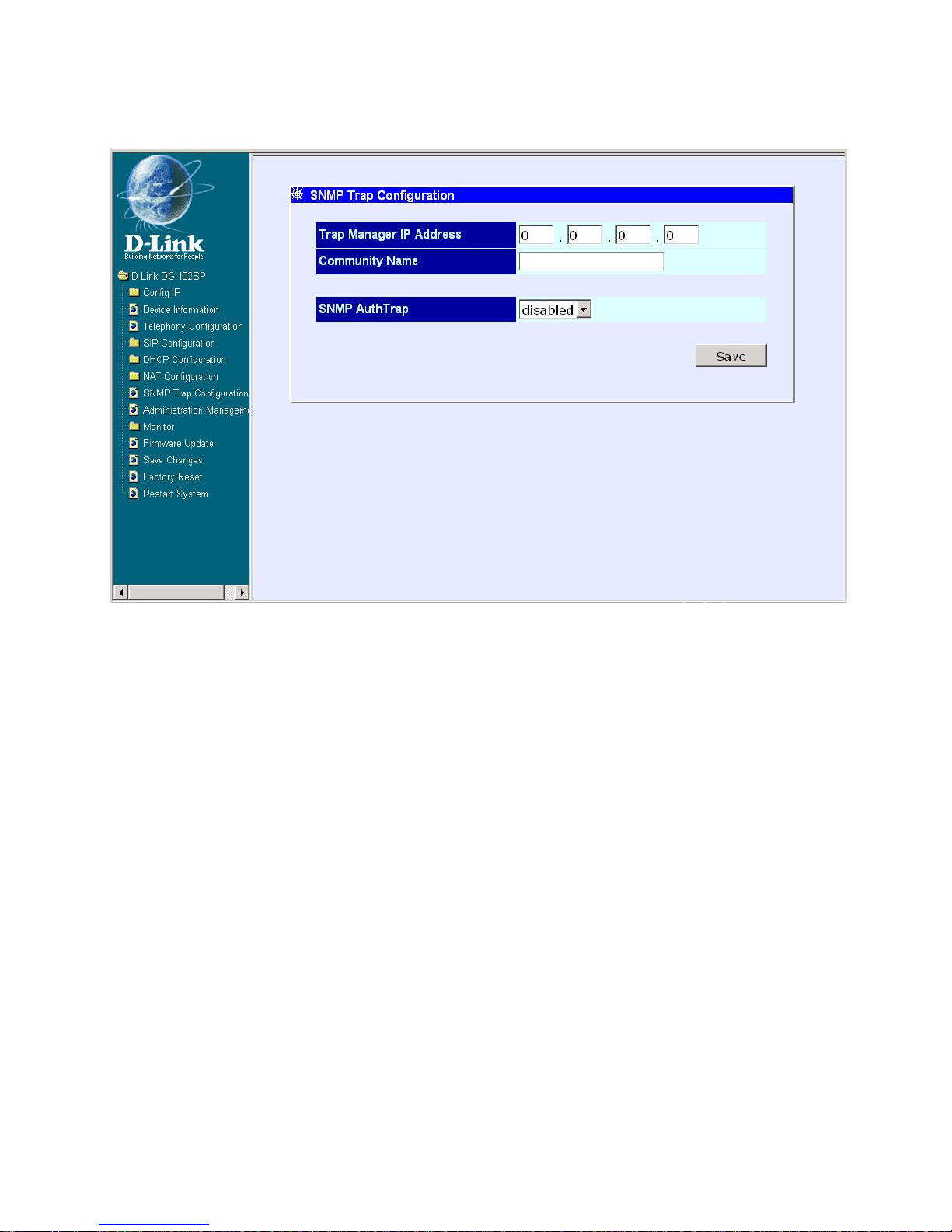
SNMP Trap Configuration
SNMP Trap Configuration window
The items on this window are described below:
Click on the Save button at the bottom right of the window to save the settings.
T rap Manager IP Address: The IP address of the trap receiving st ation.
Community Name: A user-defined SNMP community name.
SNMP AuthT rap: This allows you to enable or disable the SNMP trap.
Page 27
27
Using Web-Based Management
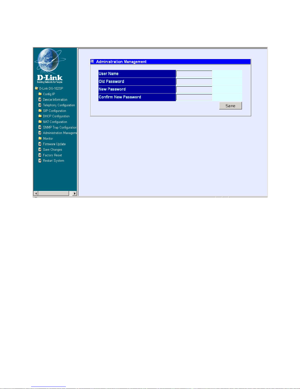
Administration Management
Administration Management window
To add or change a User Account, fill in the appropriate information in the User
Name, Old Password (if applicable), New Password, and Confirm New
Password fields. Click on the Save button to keep the settings.
Page 28
28
Using Web-Based Management
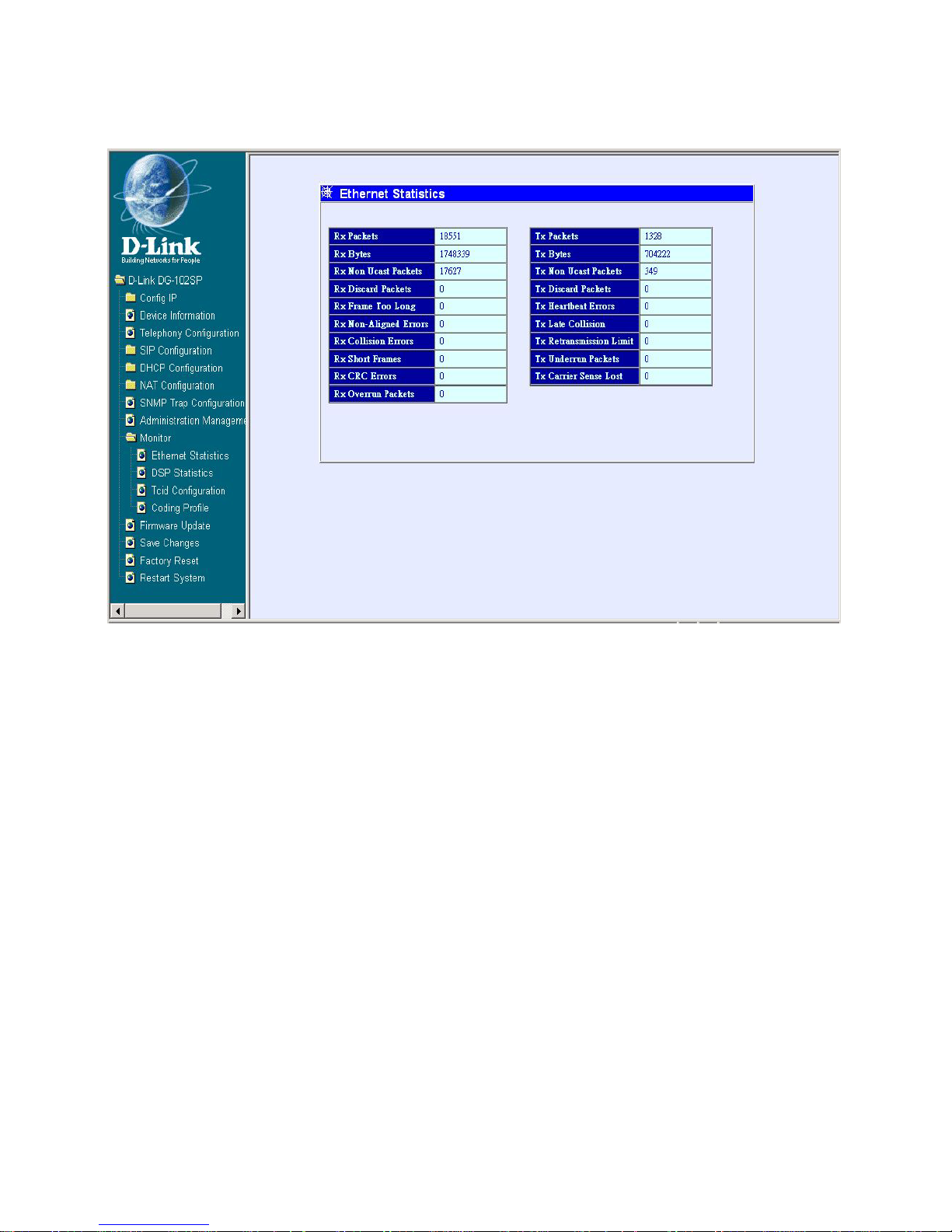
Ethernet Statistics
Ethernet Statistics window
The items on this window are described below:
Rx Packets: The total number of packets received by the device.
Rx Bytes: The total number of bytes contained in packets received by
the device.
Rx Non Ucast Packets: The number of non-unicast packets received
by the device.
Rx Discard Packets: The number of packets dropped by the device.
Rx Frame Too Long: The number of packets that are larger than the
1514 Ethernet packet limit.
Rx Non-Aligned Errors: The number of packets that are not aligned
properly.
Page 29

29
Rx Collision Errors: The number of collision errors.
Rx Short Frames: The number of packets smaller than the 64-octet
minimum.
Rx CRC Errors: The number of packets received that failed the CRC
checksum test.
Rx Overrun Packets: The number of packets received that exceed the
1518 octet maximum length imposed on Ethernet packets. Overrun
packets are generated by some proprietary software applications.
Tx Packets: The total number of valid packets transmitted by the device
since the last reset.
Tx Bytes: The total number of bytes transmitted by the device.
Tx Non Ucast Packets: The number of non-unicast packets sent.
Tx Discard Packets: The number of packets dropped by the device.
Tx Heartbeat Errors: The number of heartbeat errors. This relates to an
internal timing function.
Tx Late Collision: The number of late collisions.
Tx Retransmission Limit: The number of times the device had to
retransmit packets.
Tx Underrun Packets: This counter shows the number of runt packets
transmitted by the device that are less than the allowed 64-octet minimum
length. Underrun packets occur due to jam signals generated by collisions,
backpressure, etc.
Tx Carrier Sense Lost: The number of times packets were lost due to
carrier sense lost.
Using Web-Based Management
Ethernet Statistics
Page 30
30
Using Web-Based Management
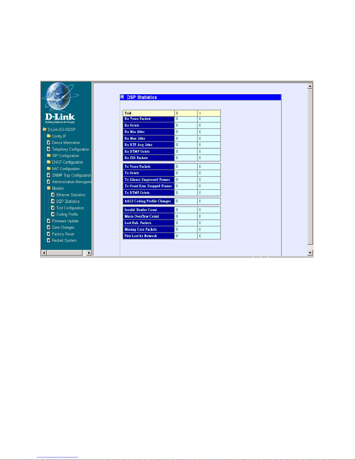
DSP Statistics
DSP Statistics window
This window displays a variety of DSP statistics.
Page 31
31
Using Web-Based Management
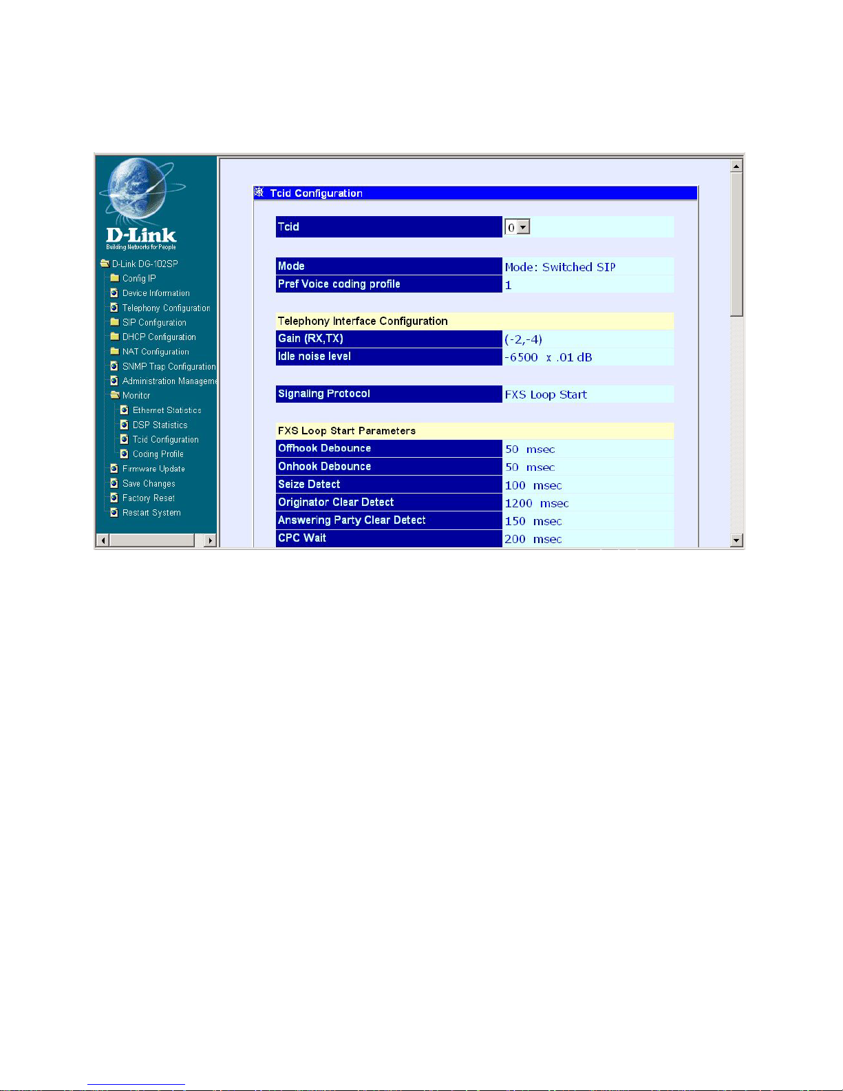
Tcid Configuration
Tcid Configuration window
This read-only window displays a variety of Tcid configuration settings.
Page 32

32
Using Web-Based Management
Coding Profile
Coding Profile window
This read-only window displays various Coding Profile settings.
Page 33
33
Using Web-Based Management
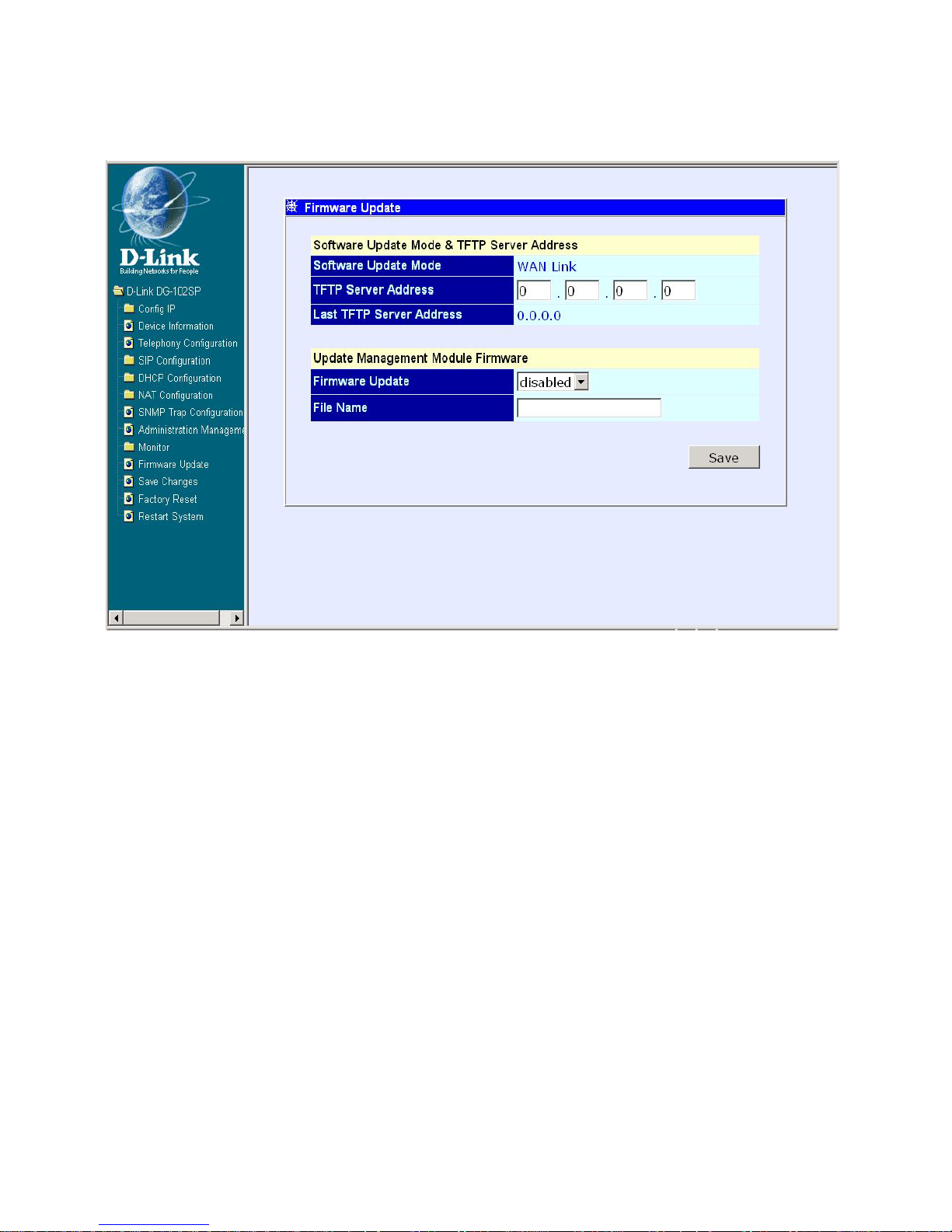
Firmware and Configuration Update
Firmware and Configuration Update window
The items on this window are described below:
Click on the Save button at the bottom right of the window to save the settings.
Software Update Mode: This specifies downloading the image file through
a WAN Link.
TFTP Server Address: The IP address of the TFTP server where the
runtime or configuration file is located. This entry is used only if the
Firmware Update is set to Enable.
Last TFTP Server Address: This is a read-only field that displays the IP
address of the last TFTP server to be accessed.
Firmware Update: Determines whether or not the device will try to look
for a runtime image file on the TFTP server.
File Name: The complete path and filename of the runtime image file on
your TFTP server to be uploaded to the device.
Page 34
34
Using Web-Based Management
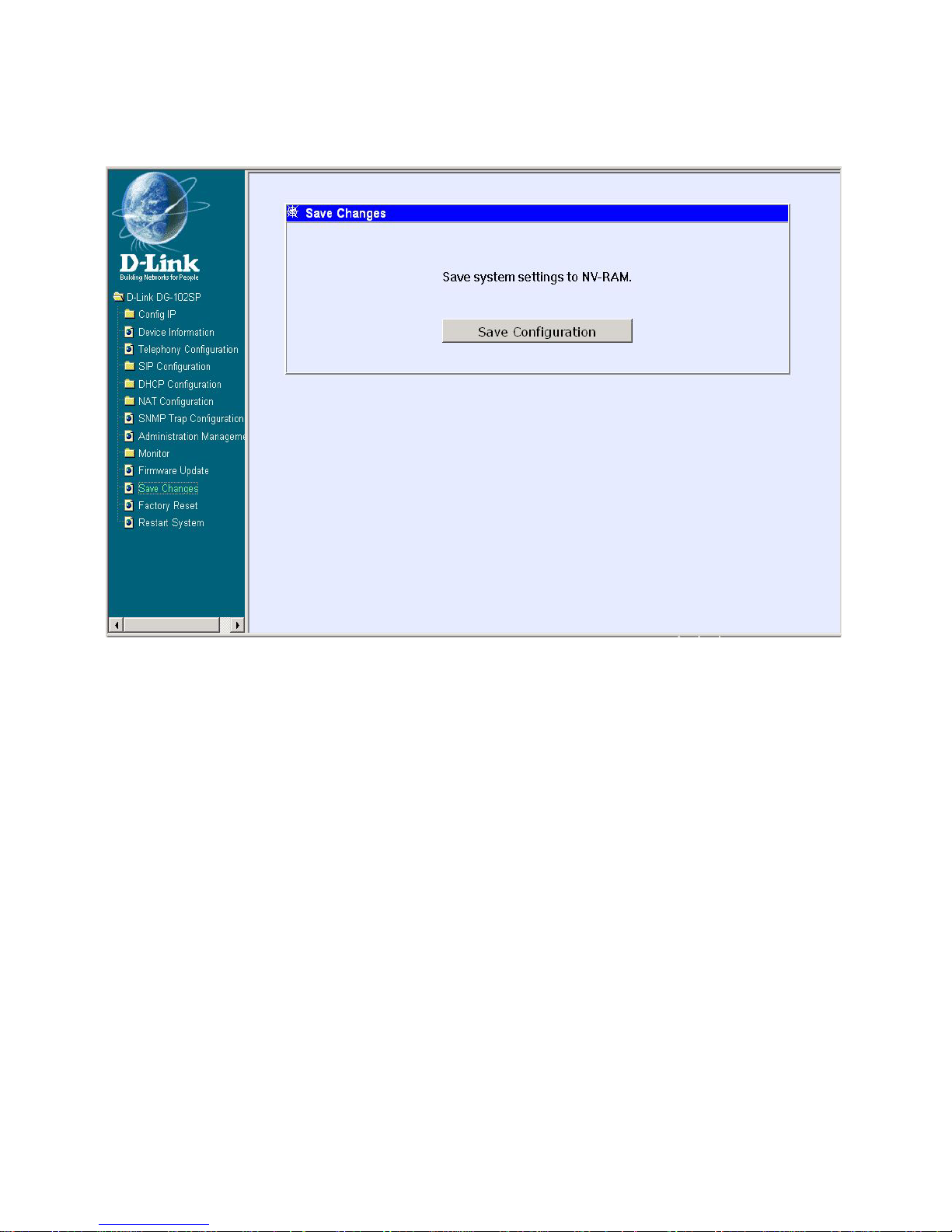
Save Changes
Save Changes window
After the settings have been saved to NV-RAM, they will become the default
settings for the device, and they will be used every time it is powered on, reset
or rebooted. The only exception to this is a factory reset, which will clear all
settings and restore them to the initial values present when the device was
purchased.
Click on the Save Configuration button at the bottom of the window to save
the system settings to NV -RAM.
Page 35
35
Using Web-Based Management
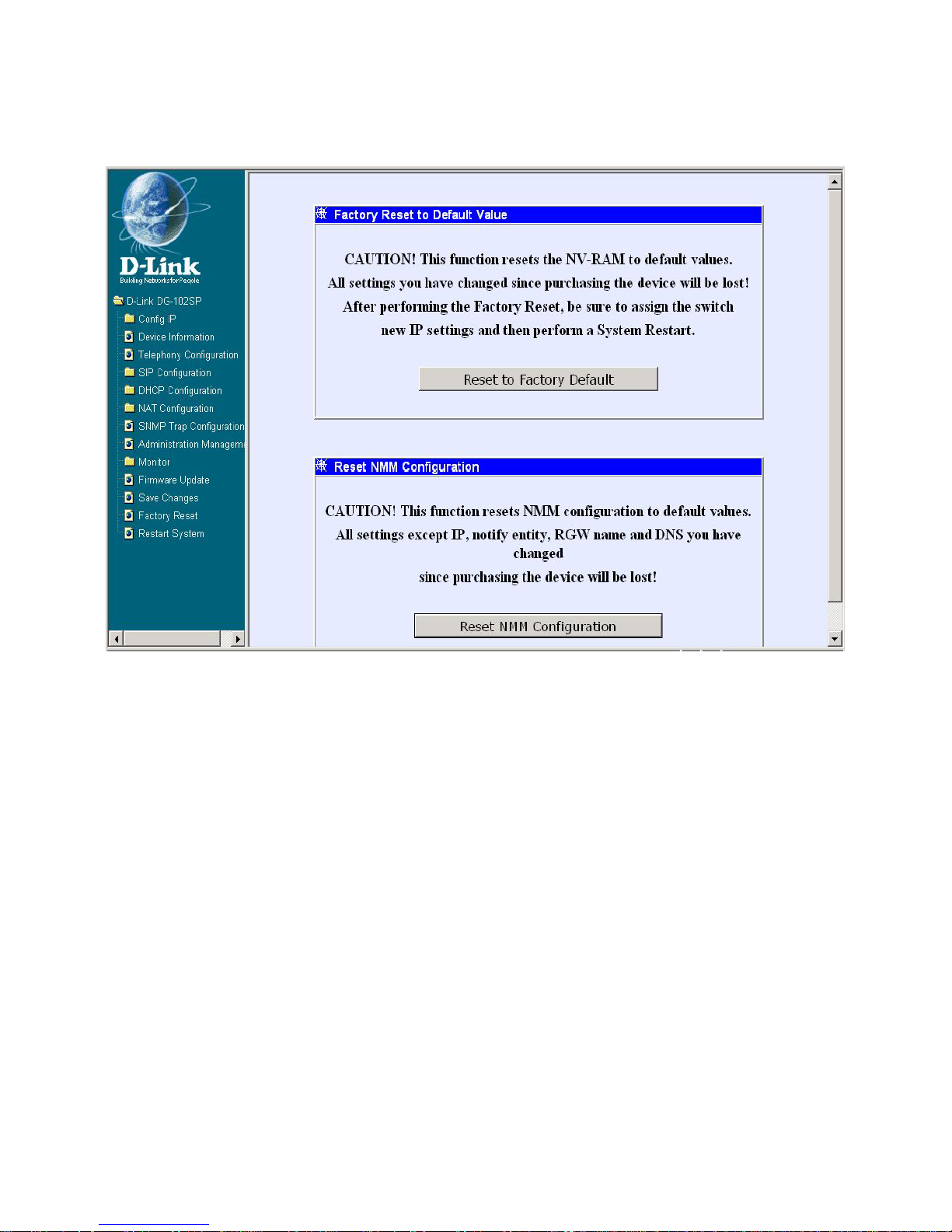
Factory Reset
Factory Reset to Default Value window
Before performing a Factory Reset, be absolutely certain that this is what you
want to do. Once the reset is complete, all of the device’s settings stored in NV RAM will be erased and restored to the values present when the device was
purchased.
Note: After performing the Factory Reset, make sure to redefine the IP settings
for the device in the IP Configuration menu. Then perform a Restart System on
the device. After these three procedures are performed, your Factory Reset is
complete.
Click on the Reset to Factory Default button at the bottom of the window to
reset the NV -RAM to the default values that were present when you purchased
the device.
Page 36
36
Using Web-Based Management
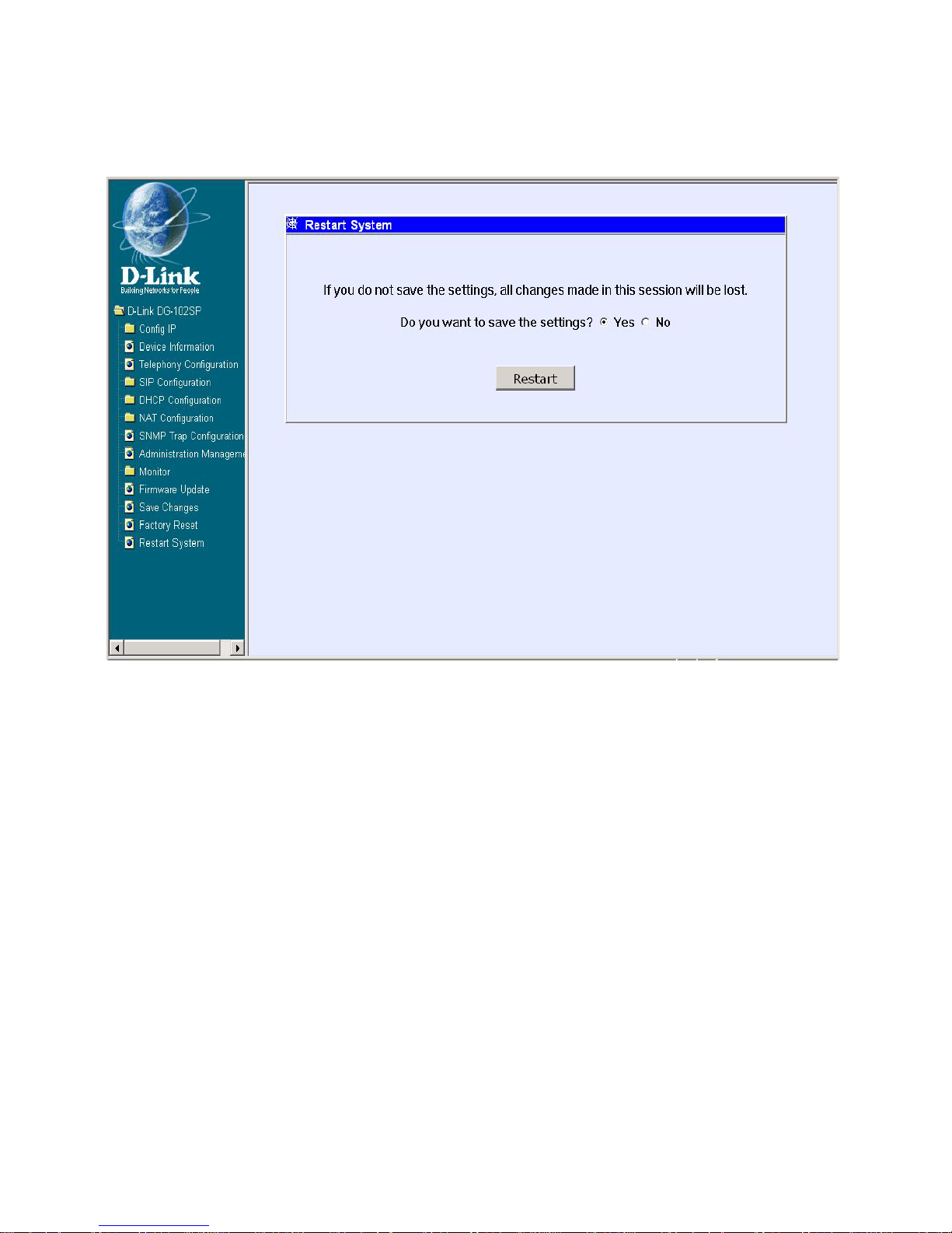
Restart System
Restart System window
To perform a reboot of the device, which resets the system, click the Restart
button.
Page 37

37
Configuration Using a Console
Setting up a Console
First-time configuration can be carried out through a “console,” that is, either
(a) a VT100-type serial data terminal, or (b) a computer running communications
software set to emulate a VT100. The console must be connected to the
Diagnostics port. This is an RS-232 port with a 9-socket D-shell connector and
DCE-type wiring. Make the connection as follows:
1. Obtain suitable cabling for the connection.
You can use either (a) a “null-modem” RS-232 cable or (b) an ordinary RS-
232 cable and a null-modem adapter . One end of the cable (or cable/adapter
combination) must have a 9-pin D-shell connector suitable for the
Diagnostics port; the other end must have a connector suitable for the
console’s serial communications port.
2. Power down the devices, attach the cable (or cable/adapter combination)
to the correct ports, and restore power.
3. Set the console to use the following communication parameters for your
terminal:
9600 baud
VT -100/ANSI compatible
No parity checking (sometimes referred to as “no parity”)
8 data bits (sometimes called a “word length” of 8 bits)
1 stop bit (sometimes referred to as a 1-bit stop interval)
No Flow control
Arrow keys enabled
Page 38
38
Configuration Using a Console
Setting up a Console
A typical console connection is illustrated below:
Example of a Console Connection
Configuring the VoIP Gateway Using Telnet
Once you have set an IP address for your device, you can use a Telnet program (in a VT -100 compatible terminal mode) to access and configure it. Most
of the screens are identical, whether accessed from the console port or from a
T elnet interface.
Console Usage Conventions
The console interface uses the following conventions:
Items in <angle brackets> can be toggled on or off using the space bar.
Items in [square brackets] can be changed by typing in a new value. You
can use the Backspace and Delete keys to erase characters behind and
in front of the cursor.
Page 39
39
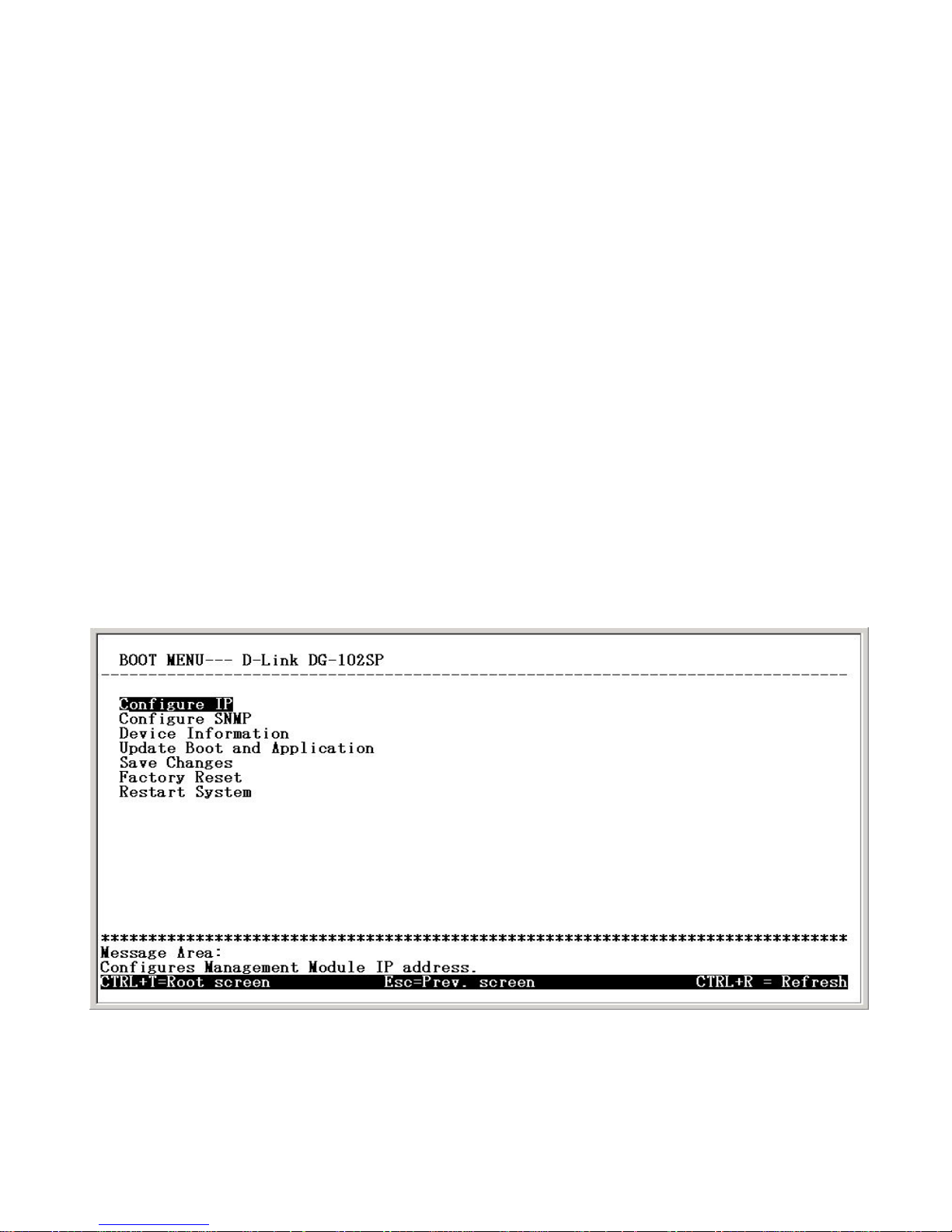
Initial Screen, First Time Connecting to the device
Configuration Using a Console
Console Usage Conventions
The up and down arrow keys, the left and right arrow keys, the Tab key,
and the Backspace key can be used to move between selected items. It
is recommended that you use the Tab key and Backspace key for moving
around the console.
Items in UPPERCASE are commands. Moving the selection to a com-
mand and pressing Enter will execute that command, e.g. APPLY, etc.
Note: The command APPLY only applies for the current session. Use Save
Changes from the Main Menu for permanent changes.
First Time Connecting to the VoIP Gateway
First make the console connection to the device and then power it on. If your
terminal (or terminal emulation program) is properly configured according to
the specifications defined above, you will see the POST test and the boot up
process. During this process, press <Ctrl+C> to reach the Boot Menu (shown
below).
If the boot up process has proceeded too far and the Boot Menu shown above
does not appear, unplug the device, plug it back in (to restart the boot up process), and press <Ctrl+C> until the Boot Menu appears.
Page 40
40
Configuration Using a Console
Configuration Settings
In order for the V oIP to function, you must provide the device with the following
information:
Where the device receives its IP settings from.
IP settings – IP Address, Subnet Mask, and Default Gateway
All of these settings are found in the first menu item in the Boot Menu named IP
Configuration.
Configure IP
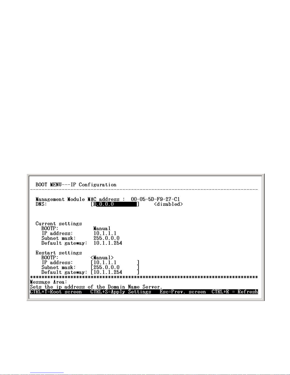
Use the <Tab> key to highlight the first menu item Configure IP and press <Enter>. The IP Configuration screen will now be displayed:
Boot Menu—IP Configuration screen
Page 41

41
Configuration Using a Console
Configure IP
DNS: Entering the IP address for the closest DNS server in this field
enables the DNS function.
BOOTP: Use the <Sp ace> key to select the method that the VoIP gateway will use to obtain its IP settings once it is rebooted. Choices include:
Manual: When Manual is selected, the V oIP gateway will obt ain its IP
settings from the fields located just below.
BOOTP: When BOOTP is selected, the VoIP gateway will attempt to
obtain its IP settings from a BOOTP server located on your LAN.
DHCP: When DHCP is selected, the VoIP gateway will attempt to ob-
tain its IP settings from a DHCP server located on your LAN.
IP Address: Enter an IP address for the V oIP gateway.
Subnet Mask: Enter a subnet mask for the VoIP gateway.
Default Gateway: Enter the IP address of the WAN device (usually a
router) you are using to make the WAN connection.
After you have finished, press <Ctrl+S> to save changes to RAM. Next, press
the <Esc> key to return to the Boot Menu. Position the cursor over the Save
Changes item and press <Enter>. This will save the settings to NV-RAM so
they will still be present after powering off or restarting the device. Position the
cursor over the Restart System item and press <Enter> for the changes to
take effect.
Your VoIP is now configured for use.
Configuring the VoIP Gateway Using a Web
Browser
Setting Up the Connection
In order to use a web browser to configure the VoIP gateway, you must make
sure it has a valid Ethernet connection to a PC or LAN via its LAN or WAN
ports.
Page 42
42
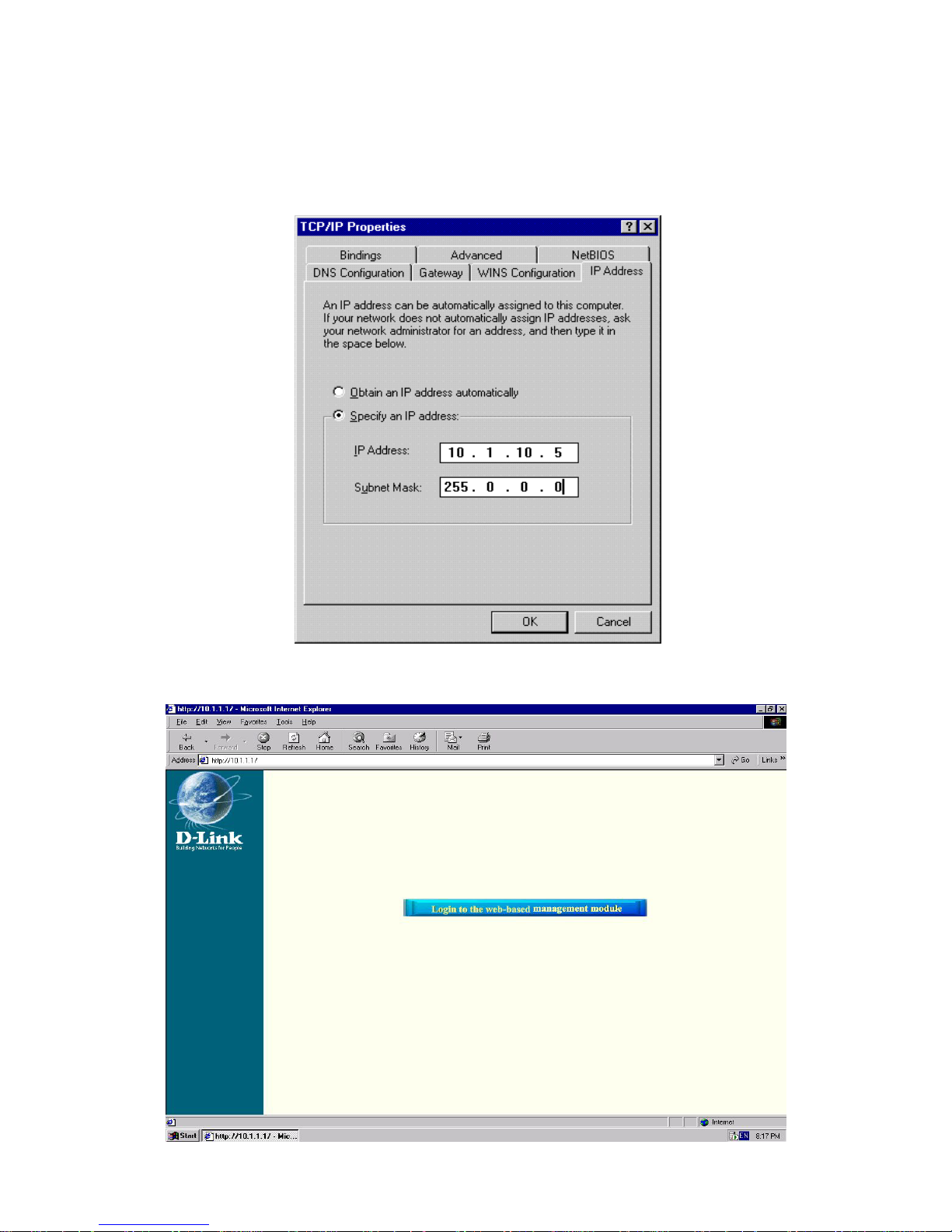
The VoIP gateway comes with a default IP address of 10.1.1.1. You must
make sure your computer is in the same Subnet as the V oIP gateway. You can
do this by changing the IP address of the computer using the screen shown
below.
Configuration Using a Console
Configuring the VoIP Gateway Using a Web Browser
Once this is done, run any browser on the computer and point it to the default
IP address of the VoIP as shown below.
Initial Window, First Time Connecting to the Web-Based Management Module
Page 43
43
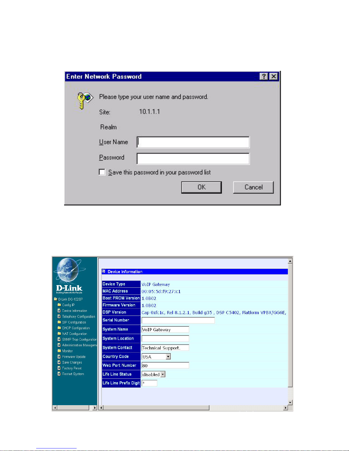
Click on the Login to the web-based management module button in the middle
of the window . The following window will be displayed:
Configuration Using a Console
Configuring the VoIP Gateway Using a Web Browser
Initially , the VoIP gateway does not have a Username or Password. To log in,
simply click on the OK button.
The following window will be displayed:
Device Information window
Page 44
44
Configuration Using a Console
Configuring the VoIP Gateway Using a W eb Browser
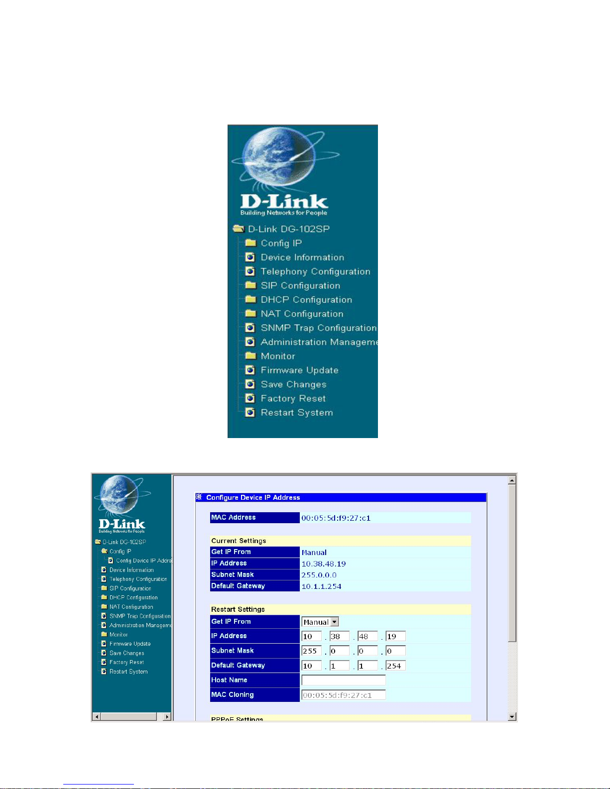
To begin configuring the device, click on the Config IP folder on the left-hand
side of the window (shown below).
Next, click on Config Device IP Address. The following window will appear:
Configure Device IP Address window
Page 45

45
Configuration Using a Console
Configuring the VoIP Gateway Using a W eb Browser
The items on this window are described below:
Restart Settings
Get IP From: Select the method the V oIP gateway will use to obtain its IP
settings once it is rebooted. Choices include:
Manual: When Manual is selected, the VoIP gateway will obtain its IP
settings from the fields located just below.
BOOTP: When BOOTP is selected, the VoIP will attempt to obtain its
IP settings from a BOOTP server located on your LAN.
DHCP: When DHCP is selected, the VoIP will attempt to obtain its IP
settings from a DCHP server located on your LAN.
IP Address: Enter an IP address for the VoIP gateway .
Subnet Mask: Enter a subnet mask for the VoIP gateway.
Default Gateway: Enter the IP address of the WAN device (usually a
router) you are using to make the WAN connection.
Host Name: This is a user-defined host name for this V oIP Gateway.
MAC Cloning: Enter the MAC address for MAC Cloning. (This function is not
supported on this version)
PPPoE Settings (for DSL users)
State: Enables or disables the PPPoE function.
User Name: Enter the User Name for the PPPoE function.
Password: Enter the Password for the PPPoE function.
Click on the Save button at the bottom right of the screen to save the settings.
Page 46
46
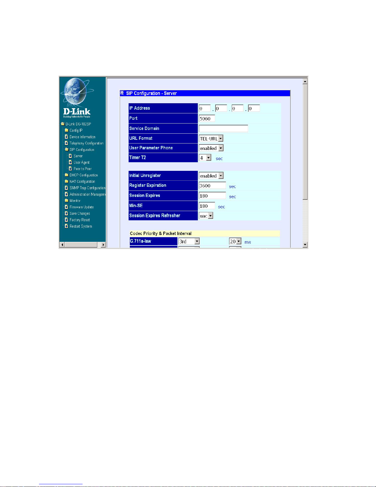
Next, click on the SIP Configuration item in the list at the left of the screen.
Then, click on Server. The following window will appear:
Configuration Using a Console
Configuring the VoIP Gateway Using a Web Browser
The items on this window are described below:
SIP Configuration window
IP Address: Enter the IP address of SIP server.
Port: Enter the port number of SIP server (Default is 5060).
Service Domain: This is a user-defined service domain for SIP server.
URL Format: This is a user-defined URL format for SIP server.
User Parameter: This is used to enable or disable the function of attach
“user=phone” parameter in SIP-URL or not.
Timer T2: This is user-defined T2 timer of SIP protocol. (Range: 4, 8, 16,
32 sec)
Initial Unregister: Enable or disable the initial unregistered function.
Register Expiration: Enter the timer of register expiration.
Page 47
47
Configuration Using a Console
Configuring the VoIP Gateway Using a Web Browser
Session Expires: Enter the timer of Expires.
Min-SE: Enter the timer of Min-SE.
Session Expires Refresher: Choose the session expires refresher:
uac or uas.
Click on the Save button at the bottom right of the screen to save the settings.
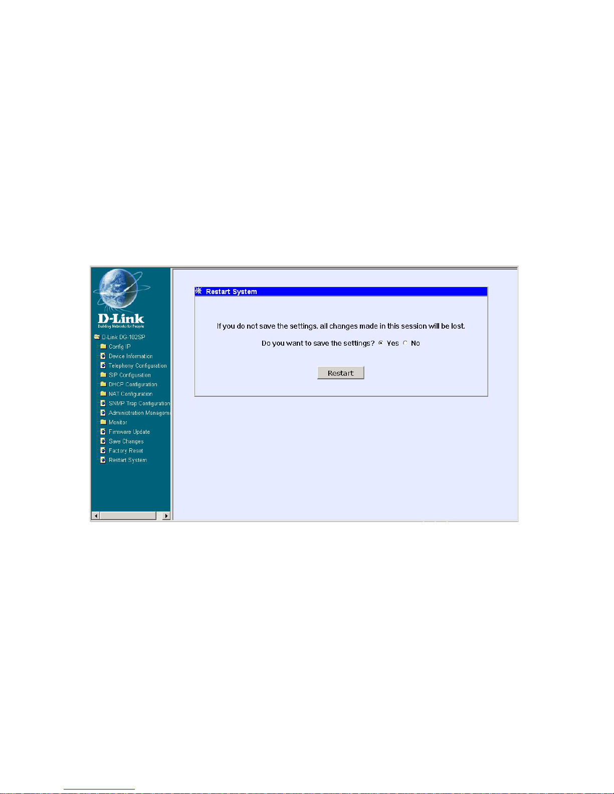
After you have finished, click on the Restart System item in the list at the left of
the screen. The following window will appear:
Select “Yes” and click on the Restart button at the bottom of the window, the
settings will be saved to NV -RAM and reboot system.
Your VoIP is now configured for use.
Restart System window
Page 48
48
Using the Boot Menu
To access the Boot Menu, you must first make sure the console is connected
to the Diagnostics port (an RS-232 port with a 9-socket D-shell connector and
DCE-type wiring) and the appropriate cabling for the connection is being used.
Please see the previous section, “Configuration,” for additional information. Next,
power the device on by simply plugging it in. Y ou will see the POST test and the
boot up process. During this process, press <Ctrl+C> to reach the Boot Menu.
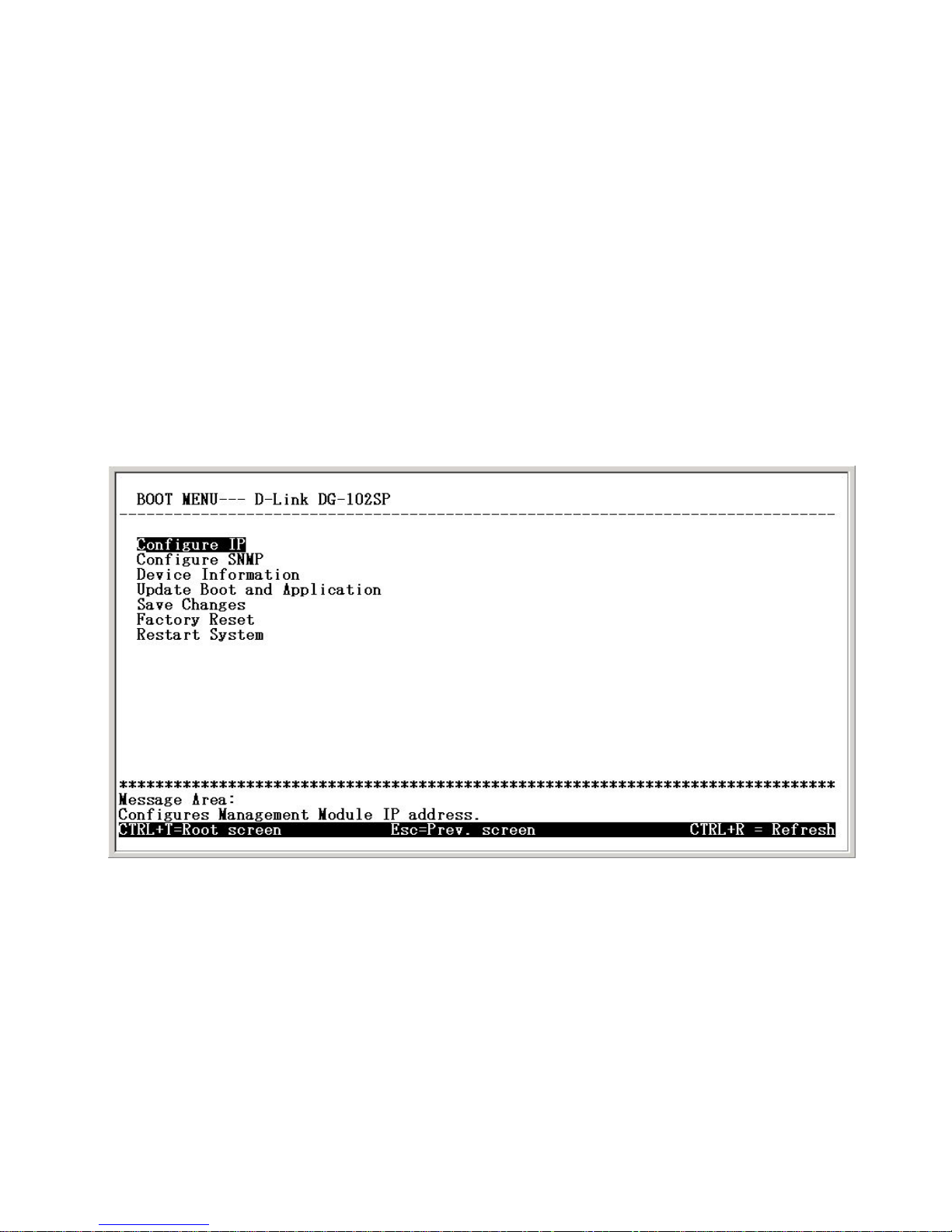
If the boot up process has proceeded too far and the Boot Menu shown below
does not appear, unplug the device, plug it back in (to restart the boot up process), and press <Ctrl+C> until the Boot Menu appears.
Boot Menu—Opening screen
Configuring the IP
This screen allows you to enter information necessary for the initial configuration of this device.
Page 49
49
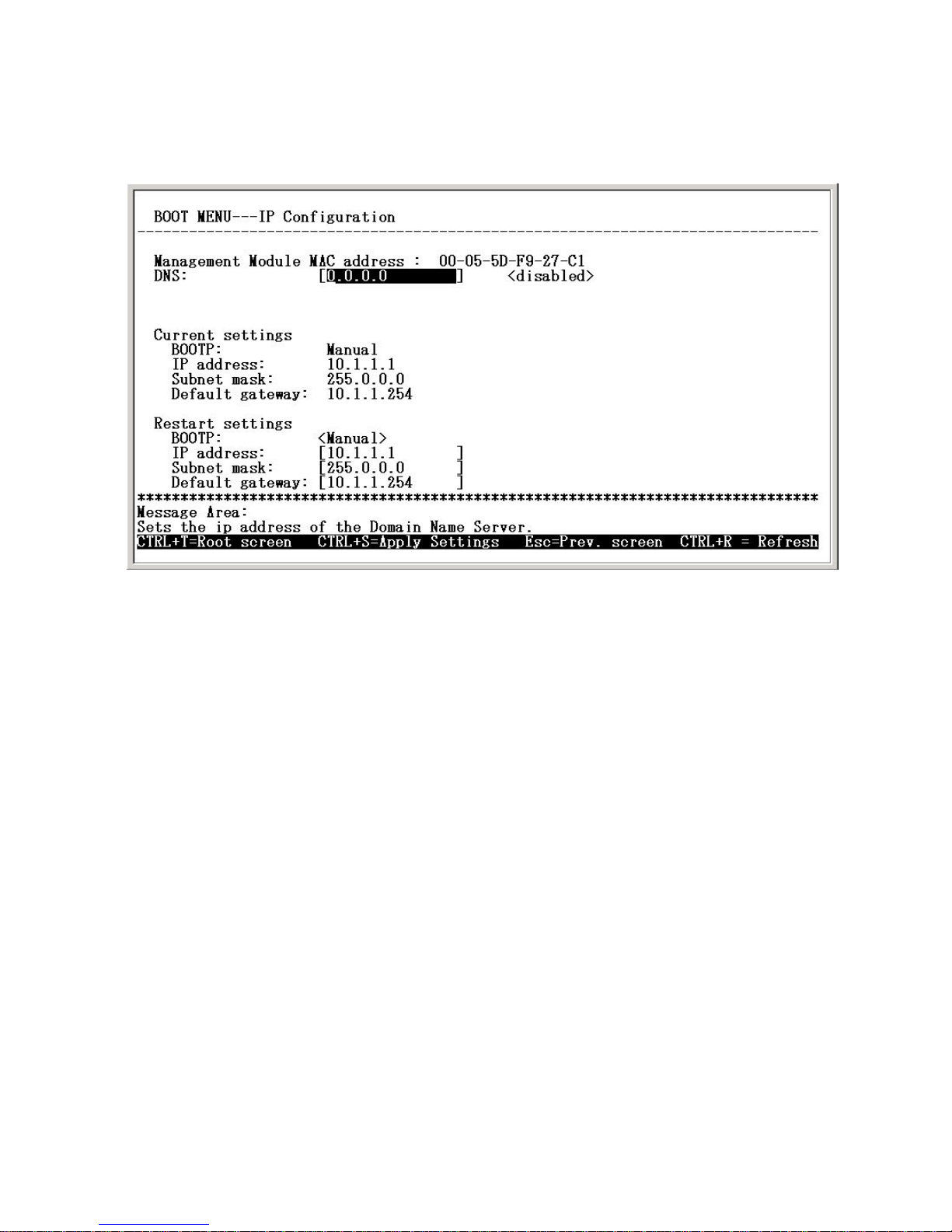
Use the arrow keys to highlight the first menu item on the Boot Menu, Configure
IP, and press <Enter>. The IP Configuration screen will be displayed:
Using the Boot Menu
Each item on the IP Configuration screen is described below:
DNS: Enter the IP address for the closest DNS server in this field if en-
ables the DNS function.
BOOTP: Use the <Space> key to select the method that the VoIP gate-
way will use to obtain its IP settings once it is rebooted (restarted). Choices
include:
Manual: When Manual is selected, the V oIP gateway will obt ain its IP
settings from the fields located just below.
BOOTP: When BOOTP is selected, the VoIP gateway will attempt to
obtain its IP settings from a BOOTP server located on your LAN.
DHCP: When DHCP is selected, the V oIP gateway will attempt to ob-
tain its IP settings from a DHCP server located on your LAN.
IP address: Enter an IP address for the VoIP gateway .
Subnet mask: Enter a subnet mask for the V oIP gateway.
Default gateway: Enter the IP address of the WAN device (usually a
router) you are using to make the WAN connection
.
Boot Menu—IP Configuration screen
Configuring the IP
Page 50
50
Using the Boot Menu
After you have finished, press <Ctrl+S> to save changes to RAM. Next, press
the <Esc> key to return to the Boot Menu. Position the cursor over the Save
Changes item and press <Enter>. This will save the settings to NV-RAM so
they will still be present after powering off or restarting the device. Position the
cursor over the Restart System item and press <Enter> for the changes to
take effect. Your VoIP is now configured for use.
Configuring the IP
Configuring the SNMP
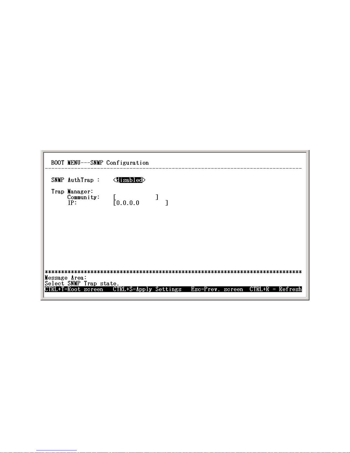
This screen allows you to set an SNMP trap manager.
Boot Menu—SNMP Configuration screen
Each item on the SNMP Configuration screen is described below:
SNMP AuthT rap: Enables or disables the SNMP trap function
Community: Enter the community name of the trap manager.
IP: Enter the IP address of the trap manager.
Page 51
51
Using the Boot Menu
Device Information
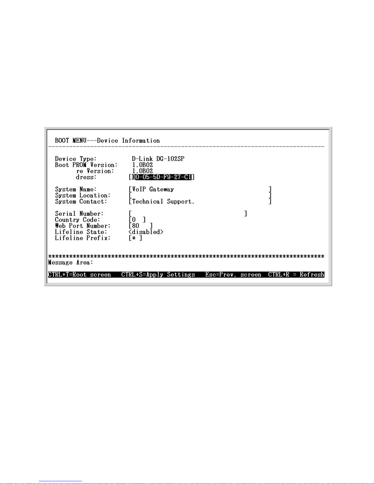
This screen displays various types of information about the DG-102SP as well
as allowing you to enter information pertaining to name, location, and how to
reach the person responsible for maintaining the device.
Use the arrow keys to highlight the second menu item on the Boot Menu, Device Information, and press <Enter>. The Device Information screen will be
displayed:
Boot Menu—Device Information screen
Each item on the Device Information screen is described below:
Device Type: This displays the model name of this device.
Boot PROM V ersion: This displays the version number of the device’s
startup code.
Firmware Version: This displays the version number of the device’s
runtime code.
MAC Address: This displays the MAC address of this device.
System Name: This is a user-defined name for this device.
System Location: This is a user-defined physical location of the
device.
Page 52
52
System Contact: This is user-defined contact information for the person or
department responsible for the maintenance of this device.
Serial Number: This displays the serial number of this device
Country Code: This is a user-defined country code for this device. < 0:USA
(Default), 1:Japan, 2:Hong Kong, 3:Sweden, 4:China >
Web Port Number: This is a user-defined web port number
Lifeline State: Enables or disables the Lifeline function
Lifeline prefix: This is a user-defined Lifeline prefixed key for this device. (Default
is “#” key)
Using the Boot Menu
Device Information
Update Boot and Application
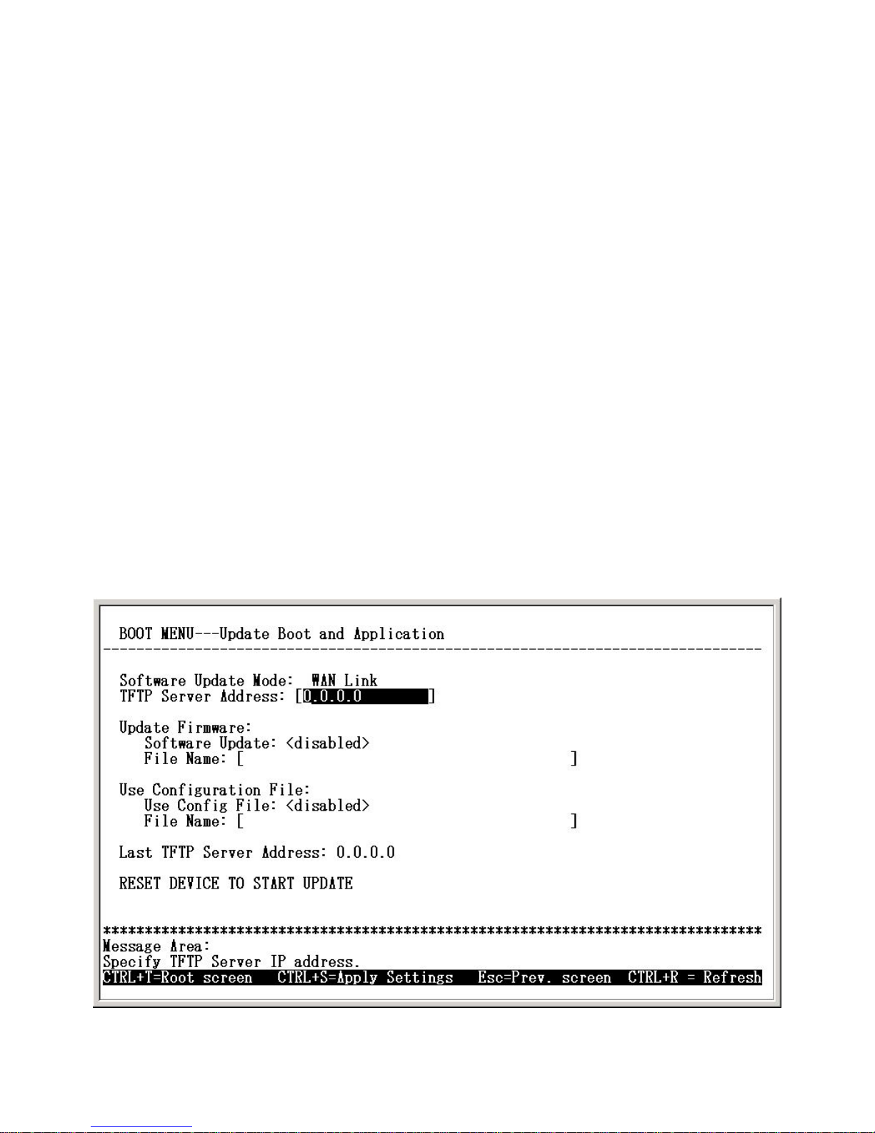
New software can be downloaded from a TFTP server.
Use the arrow keys to highlight the third menu item on the Boot Menu, Update
Firmware and Configuration Files, and press <Enter>. The Update Boot and
Application screen will be displayed:
Boot Menu—Update Boot and Application screen
Page 53

53
Using the Boot Menu
Update Boot and Application
Each item on the Update Boot and Application screen is described below:
Software Update Mode: This specifies downloading the image file
through a WAN Link.
TFTP Server Address: The IP address of the TFTP server where the
runtime or configuration file is located. This entry is used only if the
Firmware Update is set to Enable.
Software Update: Determines whether or not the device will try to
look for a runtime image file on the TFTP server.
File Name: The complete path and filename of the runtime image file
on your TFTP server to be uploaded to the device.
Use Configuration File: Toggle to Enabled to use the settings in a
configuration text file when the device is reset (rebooted).
File Name: The complete path and filename on the TFTP server for
the desired configuration file.
Last TFTP Server Address: This is a read-only field that displays the
IP address of the last TFTP server to be accessed.
Save Changes
T o save all the changes made in the current session to the device’s flash memory ,
use the arrow keys to highlight the fourth menu item on the Boot Menu, Save
Changes, and press <Enter>. The Saving Settings screen will be displayed:
Page 54

54
Using the Boot Menu
Save Changes
Boot Menu—Saving Settings screen
After the settings have been saved to NV-RAM, they will become the default
settings for the device, and they will be used every time it is powered on, reset,
or rebooted. The only exception to this is a factory reset, which will clear all
settings and restore them to their initial values, which were present when the
device was purchased.
Factory Reset
Before performing a Factory Reset, be absolutely certain that this is what you
want to do. Once the reset is done, all of the device’s settings stored in NVRAM will be erased and restored to values present when the device was
purchased.
Note: After performing the Factory Reset, make sure to redefine the IP settings
for the device in the IP Configuration menu. Then perform a Restart System on
the device. After these three procedures are performed, your Factory Reset is
complete.
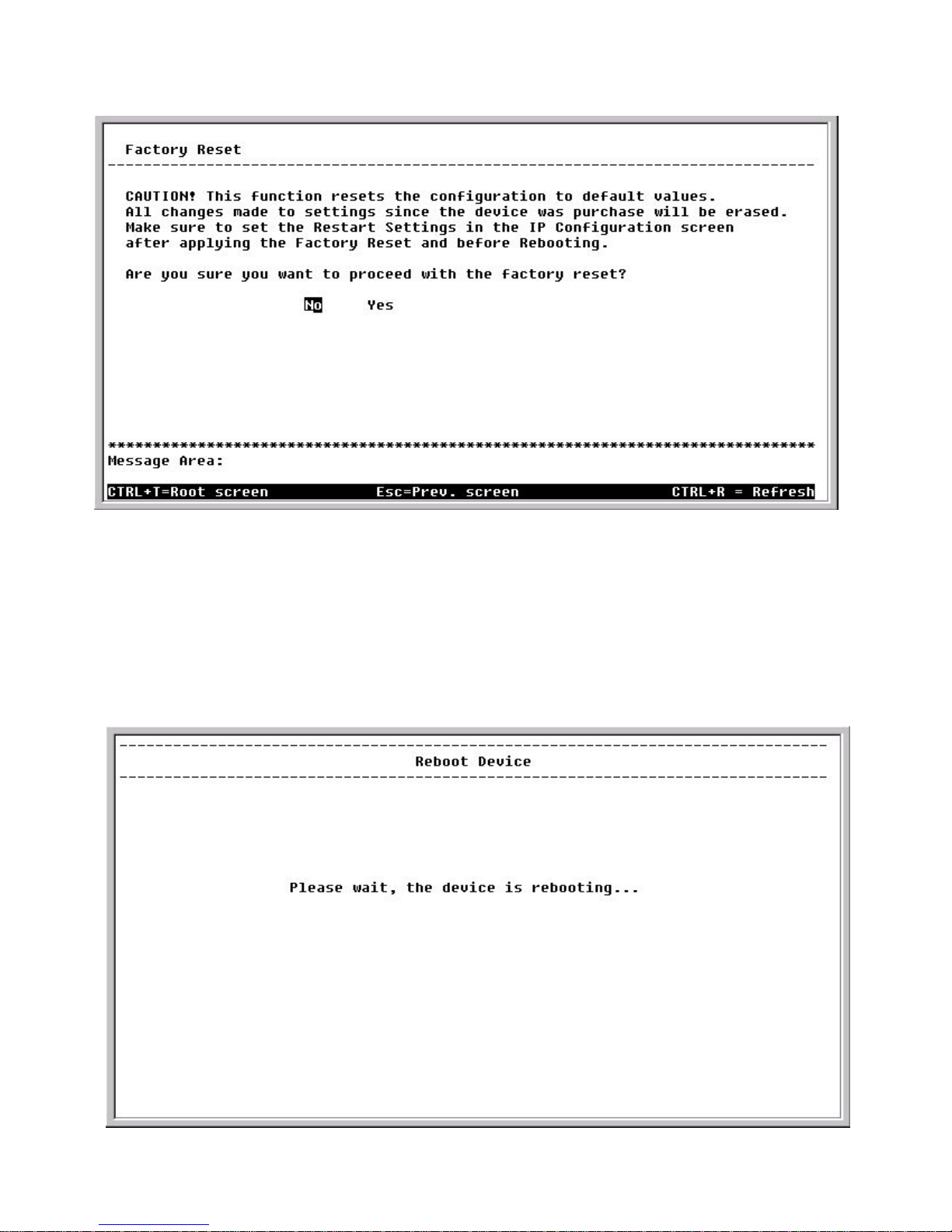
To perform a Factory Reset, use the arrow keys to highlight the fifth menu item
on the Boot Menu, Factory Reset, and press <Enter>. The Factory Reset
screen will be displayed:
Page 55
55
Using the Boot Menu
Factory Reset
Boot Menu—Factory Reset screen
Restart System
To perform a system reset, use the arrow keys to highlight the last menu item
on the Boot Menu, Restart System, and press <Enter>. The following Reboot
Device screen will be briefly displayed:
Boot Menu—Restart System screen
Page 56

56
Command Line Interface
The DG-102SP VoIP Gateway offers a line-at-a-time prompt and response
scheme to execute various configuration instructions. The interface displays a
single prompt character ggdbg> when it is ready to accept a command (ex.
ggdbg>set or ggdbg>show).
Typing a question mark after the ggdbg> prompt will display a list of helpful
user commands. Please note that all characters must be entered in lower case.
All command line examples in this chapter are in bold type.
Listed below are some of the most commonly used commands, parameter(s),
and examples of their usage.
General Setup Commands
nwdbg system reboot
Definition: This command is used to restart the device.
Parameter(s): None.
Example: nwdbg system reboot
nwdbg save changes
Definition: This command is used to save the configuration changes
into flash memory and restart the device.
Parameter(s): None.
Example: nwdbg save changes
nwdbg factory reset
Definition: This command is used to set the DG-102SP back to its
default settings and then restart the device.
Parameter(s): None.
Example: nwdbg factory reset
Page 57

57
Command Line Interface
General Setup Commands
nwdbg un <USERNAME>
Definition: This command sets the username if there is a username
string, or shows the username/password if only nwdbg
un is typed.
Parameter(s): <USERNAME, maximum string length is 12
characters>
Example: nwdbg un 123456789012
nwdbg pw <PASSWORD>
Definition: This command sets the password if there is a
password string, or shows the username/password if
only nwdbg pw is typed.
Parameter(s): <PASSWORD, maximum string length is 12
characters>
Example: nwdbg pw
nwdbg slic <0|1>
Definition: This command changes the Subscriber Line Interface
Circuit (SLIC) state to standby or active, or shows the
SLIC state if only nwdbg slic is typed.
Parameter(s): <slic state, 0 : standby, 1 : active >
Example: nwdbg slic 0
Page 58

58
Command Line Interface
General Setup Commands
nwdbg dtmf_relay <0|1>
Definition: This command turns the Dual Tone Multiple Frequency
(DTMF) relay function on or off, or shows the DTMF relay
state if only nwdbg dtmf_relay is typed.
Parameter(s): <0 : off, 1 : on>
Example: nwdbg dtmf_relay 0
nwdbg mac <MAC ADDRESS>
Definition: This command sets the MAC address of the voice link,
or shows the MAC address if only nwdbg mac is
typed.
Parameter(s): <MAC ADDRESS, the format is XX:XX:XX:XX:XX:XX>
Example: nwdbg mac 00:50:ba:08:24:56
nwdbg ip <dhcp|bootp|manual>
Definition: This command sets the software boot mode to DHCP,
BOOTP, or Manual mode. If only nwdbg ip is typed, this
command shows the IP configuration.
DHCP: While the system is booting, the system acts as
a DHCP client.
BOOTP: While the system is booting, the system acts
as a BOOTP client. This mode is used to set the device’s
IP address and upgrade the software.
Manual: While the system is booting, the system uses a
fixed IP address. The fixed IP address can be set by
nwdbg ip <IP ADDRESS>.
Parameter(s): <dhcp|bootp|manual>
Example: nwdbg ip dhcp
Page 59

59
Command Line Interface
General Setup Commands
nwdbg ip <IP ADDRESS>
Definition: This command sets the fixed IP address, which is used
as the system’s IP address if the software boot mode is
Manual mode. If only nwdbg ip is typed, this command
shows the IP configuration.
Parameter(s): <IP ADDRESS>
Example: nwdbg ip 10.1.1.120
nwdbg mask <SUBNET MASK>
Definition: This command sets the fixed subnet mask, which is
used as the system’s subnet mask if the software boot
mode is Manual mode. If only nwdbg mask is typed, this
command shows the IP configuration.
Parameter(s): <SUBNET MASK>
Example: nwdbg mask 255.0.0.0
nwdbg gw <GA TEW A Y IP>
Definition: This command sets the fixed GW address, which is used
as the system’s GW address if the software boot mode
is Manual mode. If only nwdbg gw is typed, this
command shows the IP configuration.
Parameter(s): <GATEWAY IP>
Example: nwdbg gw 10.1.1.254
Page 60

60
Command Line Interface
General Setup Commands
nwdbg tftp <0|1>
Definition: This command sets the software download link to either
a WAN link or a LAN link. If only nwdbg t ftp is typed, this
command shows the download link.
Parameter(s): <0:WAN link, 1:LAN link>
Example: nwdbg tftp 0
nwdbg ca <NOTIFY ENTITY>
Definition: This command sets the address of notify entity. If only
nwdbg ca is typed, this command shows the address.
Parameter(s): <NOTIFY ENTITY, the format can be:
localName@[domainName|ip]:port or
[domainName|ip]:port or [domainName|ip]>
Example: nwdbg ca 10.1.40.100:2427
nwdbg rgw <RGW NAME>
Definition: This command sets the Residential Gateway Name. If
only nwdbg rgw is typed, this command shows the
RGW NAME.
Parameter(s): <RGW NAME>
Example: nwdbg rgw [RGW_1]
nwdbg dns <DNS IP>
Definition: This command sets the Domain Name Server’s IP address. If
only nwdbg dns is typed, this command shows the DNS IP/
ST ATE.
Parameter(s): <DNS IP>
Example: nwdbg dns 10.1.1.5
Page 61

61
nwdbg dns <disable|enable>
Definition: This command turns on/off the DNS function. If only
nwdbg dns is typed, this command shows the DNS
IP/STATE.
Parameter(s): [disable | enable]
Example: nwdbg dns disable
nwdbg country <code>
Definition: This command provides country code setting interface
to config the tone frequency for different country. If only
nwdbg country is typed, this command shows the
COUNTRY CODE.
Parameter(s): <0:USA (Default), 1:Japan, 2:Hong Kong, 3:Sweden>
Example: nwdbg country 1
nwdbg config
Definition: This command shows all the configuration settings
made by nwdbg commands.
Parameter(s): None.
Example: nwdbg config
Command Line Interface
General Setup Commands
Page 62

62
ping <DEST IP> <OPTIONS>
Definition: This command lets the user ping an IP address from
the device.
Parameter(s): <DEST IP: The host ip address>
<OPTIONS, -t : Ping the specifed host until stopped
(type SPACE).
-n count: Number of echo requests to send.
-w timeout: Timeout in seconds to wait for each reply.
-i interval: The interval in half-seconds between two
echo requests.>
Example: ping 10.1.1.6 -n 100 -w 2 -i 1
Command Line Interface
General Setup Commands
TFTP Client Setup Commands
When the user enters tftp, the screen will show all commands about the TFTP
client:
ggdbg>tftp
tftp srvip <IP ADDRESS> – set the IP address of TFTP server
tftp get <FILENAME> – get the remote image file
If <FILENAME> is not specified,
the image file name in
EEPROM will be employed.
tftp update – update the image in flash
Current Settings :
TFTP Server IP Address : 172.16.6.245
Image File Name : 102nmm01.tfp
Page 63

63
Command Line Interface
TFTP Client Setup Commands
tftp srvip <IP ADDRESS>
Definition: This command sets the IP address of the TFTP server.
The image must be resident on that TFTP server. If the
IP address is invalid, the message ERROR will be
displayed.
Example: ggdbg>tftp srvip 172.16.6.245
OK
tftp get <FILENAME>
Definition: Gets the image from the TFTP server. The <FILENAME>
is the name of the image on the TFTP server . If any error
occurs during the image download, the message
ERROR will be displayed. When the user enters tftp
get, the file name in EEPROM will be employed.
Example: ggdbg>tftp get c:\102nmm.tfp
Download d:\project\dg102\102nmm.tfp ...\
OK
tftp update
Definition: This command updates the image in FLASH. The image
is downloaded for storage in DRAM. If any error occurs
during the image update, the message ERROR will be
displayed.
Example: ggdbg>tftp update
.. Erase Runtime Flash Memory ... Done
.. Program Runtime Flash Memory ... Done
OK
Page 64

64
Technical Specifications
Call Control Protocols Compliance
SIP
Voice Compression
G.71 1 (A-law and u-law), G.723.1, G .729a
Analog Voice Ports
Type: Loop-Start FXS interfaces
DTMF tone detection/generation
V.21/V.25 Modem/Fax tone detection
Echo Cancellation: G.168
Ethernet Ports
WAN: NW ay 10/100BASE-TX Fast Ethernet port s (MDI-II)
LAN: NWay 10/100BASE-TX Fast Ethernet port s (MDI-X)
IEEE 802.3 10BASE-T Ethernet compliance
IEEE 802.3u 100BASE-TX Fast Ethernet compliant
Quality of Service
Voice service is prioritized over the data traffic.
F AX Support
V .21, V.27ter , V .29, V.17 Modulation/Demodulation.
Network Protocols
TCP/IP, UDP, ARP, ICMP, TFTP, Telnet, SNMP, HTTP
DHCP: Dynamic Host Configuration Protocol server and client
NAT: Network Address T ranslation
PPP over Ethernet Client
Page 65

65
Network Management
SNMP management agent base MIB II
Telnet provisioning
Manage functions through an intuitive web-based graphical user interface
Local management console
TFTP: The built–in T rivial File T ransfer Protocol provides firmware upgrade
Security
Password Authentication Protocol/Challenge Handshake Authentication
Protocol (PAP/CHAP)
Administrative password through Telnet, Console, Web and SNMP
Technical Specifications
LEDs
General
Power
Status
Ethernet
WAN: 10/100M, Link/Act
LAN: 10/100M, Link/Act
Line
Hook/Ringing
Phone 1 to 2
Hook/Ringing
Dimensions
223.3(W) x 131.7(D) x 35(H) mm
Page 66

66
Number of Ports
One 10/100BASE-TX Fast Ethernet port (W AN)
One 10/100BASE-TX Fast Ethernet port (LAN)
Two loop-start FXS RJ-1 1 ports
One PSTN POTS RJ-11 port for Life Line
One RS-232C, DB-9 Console port
Power Supply
AC-to-DC power adapter (provided)
DC Input: 12VDC/1A
Operating Temperature
0 - 50 °C
Storage Temperature
-10 - 55 °C
Humidity
5% - 95% non-condensing
Safety
CSA International (CSA 950, UL 1950, EN 60950, IEC 950)
Emission (EMI)
FCC Class B
VCCI Class B
BSMI Class B
CE Class B
C-Tick Class B
Technical Specifications
Page 67

67
Subject to the terms and conditions set forth herein, D-Link Systems, Inc. (“D-Link”) provides this Limited
warranty for its product only to the person or entity that originally purchased the product from:
• D-Link or its authorized reseller or distributor and
• Products purchased and delivered within the fifty states of the United States, the District of
Columbia, U.S. Possessions or Protectorates, U.S. Military Installations, addresses with an
APO or FPO.
Limited Warranty: D-Link warrants that the hardware portion of the D-Link products described
below will be free from material defects in workmanship and materials from the date of original retail
purchase of the product, for the period set forth below applicable to the product type (“Warranty
Period”), except as otherwise stated herein.
1-Year Limited Warranty for the Product(s) is defined as follows:
• Hardware (excluding power supplies and fans) One (1) Year
• Power Supplies and Fans One (1) Year
• Spare parts and spare kits Ninety (90) days
D-Link’s sole obligation shall be to repair or replace the defective Hardware during the Warranty Period
at no charge to the original owner or to refund at D-Link’s sole discretion. Such repair or replacement will
be rendered by D-Link at an Authorized D-Link Service Office. The replacement Hardware need not be
new or have an identical make, model or part. D-Link may in its sole discretion replace the defective
Hardware (or any part thereof) with any reconditioned product that D-Link reasonably determines is
substantially equivalent (or superior) in all material respects to the defective Hardware. Repaired or
replacement Hardware will be warranted for the remainder of the original Warranty Period from the date
of original retail purchase. If a material defect is incapable of correction, or if D-Link determines in its sole
discretion that it is not practical to repair or replace the defective Hardware, the price paid by the original
purchaser for the defective Hardware will be refunded by D-Link upon return to D-Link of the defective
Hardware. All Hardware (or part thereof) that is replaced by D-Link, or for which the purchase price is
refunded, shall become the property of D-Link upon replacement or refund.
Limited Software Warranty: D-Link warrants that the software portion of the product (“Software”)
will substantially conform to D-Link’s then current functional specifications for the Software, as set forth
in the applicable documentation, from the date of original retail purchase of the Software for a period of
ninety (90) days (“Warranty Period”), provided that the Software is properly installed on approved
hardware and operated as contemplated in its documentation. D-Link further warrants that, during the
Warranty Period, the magnetic media on which D-Link delivers the Software will be free of physical
defects. D-Link’s sole obligation shall be to replace the non-conforming Software (or defective media)
with software that substantially conforms to D-Link’s functional specifications for the Software or to
refund at D-Link’s sole discretion. Except as otherwise agreed by D-Link in writing, the replacement
Software is provided only to the original licensee, and is subject to the terms and conditions of the
license granted by D-Link for the Software. Software will be warranted for the remainder of the original
Warranty Period from the date or original retail purchase. If a material non-conformance is incapable of
correction, or if D-Link determines in its sole discretion that it is not practical to replace the nonconforming Software, the price paid by the original licensee for the non-conforming Software will be
refunded by D-Link; provided that the non-conforming Software (and all copies thereof) is first returned
to D-Link. The license granted respecting any Software for which a refund is given automatically
terminates.
Non-Applicability of Warranty: The Limited Warranty provided hereunder for hardware and software
of D-Link’s products will not be applied to and does not cover any refurbished product and any product
purchased through the inventory clearance or liquidation sale or other sales in which D-Link, the sellers,
or the liquidators expressly disclaim their warranty obligation pertaining to the product and in that case,
the product is being sold “As-Is” without any warranty whatsoever including, without limitation, the
Limited Warranty as described herein, notwithstanding anything stated herein to the contrary.
Page 68

68
Submitting A Claim: The customer shall return the product to the original purchase point based on its
return policy. In case the return policy period has expired and the product is within warranty, the
customer shall submit a claim to D-Link as outlined below:
• The customer must submit with the product as part of the claim a written description of the
Hardware defect or Software nonconformance in sufficient detail to allow D-Link to confirm
the same.
• The original product owner must obtain a Return Material Authorization (“RMA”) number from
the Authorized D-Link Service Office and, if requested, provide written proof of purchase of
the product (such as a copy of the dated purchase invoice for the product) before the
warranty service is provided.
• After an RMA number is issued, the defective product must be packaged securely in the
original or other suitable shipping package to ensure that it will not be damaged in transit, and
the RMA number must be prominently marked on the outside of the package. Do not include any
manuals or accessories in the shipping package. D-Link will only replace the defective portion
of the Product and will not ship back any accessories.
• The customer is responsible for all in-bound shipping charges to D-Link. No Cash on Delivery
(“COD”) is allowed. Products sent COD will either be rejected by D-Link or become the
property of D-Link. Products shall be fully insured by the customer and shipped to D-Link
Systems, Inc., 17595 Mt. Herrmann, Fountain Valley, CA 92708. D-Link will not be held
responsible for any packages that are lost in transit to D-Link. The repaired or replaced
packages will be shipped to the customer via UPS Ground or any common carrier selected by
D-Link, with shipping charges prepaid. Expedited shipping is available if shipping charges are
prepaid by the customer and upon request.
D-Link may reject or return any product that is not packaged and shipped in strict compliance with the
foregoing requirements, or for which an RMA number is not visible from the outside of the package. The
product owner agrees to pay D-Link’s reasonable handling and return shipping charges for any product
that is not packaged and shipped in accordance with the foregoing requirements, or that is determined
by D-Link not to be defective or non-conforming.
What Is Not Covered: This limited warranty provided by D-Link does not cover: Products, if in D-Link’s
judgment, have been subjected to abuse, accident, alteration, modification, tampering, negligence, misuse,
faulty installation, lack of reasonable care, repair or service in any way that is not contemplated in the
documentation for the product, or if the model or serial number has been altered, tampered with, defaced
or removed; Initial installation, installation and removal of the product for repair, and shipping costs;
Operational adjustments covered in the operating manual for the product, and normal maintenance;
Damage that occurs in shipment, due to act of God, failures due to power surge, and cosmetic damage;
Any hardware, software, firmware or other products or services provided by anyone other than DLink; Products that have been purchased from inventory clearance or liquidation sales or other sales in
which D-Link, the sellers, or the liquidators expressly disclaim their warranty obligation pertaining to the
product. Repair by anyone other than D-Link or an Authorized D-Link Service Office will void this
Warranty.
Disclaimer of Other Warranties: EXCEPT FOR THE LIMITED WARRANTY SPECIFIED HEREIN, THE
PRODUCT IS PROVIDED “AS-IS” WITHOUT ANY W ARRANTY OF ANY KIND WHA TSOEVER INCLUDING,
WITHOUT LIMIT A TION, ANY W ARRANTY OF MERCHANT ABILITY , FITNESS FOR A P ARTICULAR PURPOSE
AND NON-INFRINGEMENT . IF ANY IMPLIED WARRANTY CANNOT BE DISCLAIMED IN ANY TERRITOR Y
WHERE A PRODUCT IS SOLD, THE DURA TION OF SUCH IMPLIED WARRANTY SHALL BE LIMITED TO
NINETY (90) DA YS. EXCEPT AS EXPRESSL Y COVERED UNDER THE LIMITED WARRANTY PROVIDED
HEREIN, THE ENTIRE RISK AS TO THE QUALITY , SELECTION AND PERFORMANCE OF THE PRODUCT IS
WITH THE PURCHASER OF THE PRODUCT .
Limitation of Liability: TO THE MAXIMUM EXTENT PERMITTED BY LAW, D-LINK IS NOT LIABLE
UNDER ANY CONTRACT , NEGLIGENCE, STRICT LIABILITY OR OTHER LEGAL OR EQUIT ABLE THEORY
FOR ANY LOSS OF USE OF THE PRODUCT, INCONVENIENCE OR DAMAGES OF ANY CHARACTER,
WHETHER DIRECT , SPECIAL, INCIDENT AL OR CONSEQUENTIAL (INCLUDING, BUT NOT LIMITED TO,
DAMAGES FOR LOSS OF GOODWILL, LOSS OF REVENUE OR PROFIT , WORK STOPP AGE, COMPUTER
FAILURE OR MALFUNCTION, F AILURE OF OTHER EQUIPMENT OR COMPUTER PROGRAMS TO WHICH DLINK’S PRODUCT IS CONNECTED WITH, LOSS OF INFORMA TION OR DA TA CONT AINED IN, STORED ON,
OR INTEGRA TED WITH ANY PRODUCT RETURNED TO D-LINK FOR W ARRANTY SERVICE) RESUL TING
FROM THE USE OF THE PRODUCT, RELA TING TO W ARRANTY SERVICE, OR ARISING OUT OF ANY
BREACH OF THIS LIMITED WARRANTY, EVEN IF D-LINK HAS BEEN ADVISED OF THE POSSIBILITY OF
SUCH DAMAGES. THE SOLE REMEDY FOR A BREACH OF THE FOREGOING LIMITED WARRANTY IS
Page 69

69
REP AIR, REPLACEMENT OR REFUND OF THE DEFECTIVE OR NON-CONFORMING PRODUCT . THE MAXIMUM
LIABILITY OF D-LINK UNDER THIS WARRANTY IS LIMITED TO THE PURCHASE PRICE OF THE PRODUCT
COVERED BY THE W ARRANTY. THE FOREGOING EXPRESS WRITTEN WARRANTIES AND REMEDIES
ARE EXCLUSIVE AND ARE IN LIEU OF ANY OTHER W ARRANTIES OR REMEDIES, EXPRESS, IMPLIED OR
STATUTORY
Governing Law: This Limited Warranty shall be governed by the laws of the State of California. Some
states do not allow exclusion or limitation of incidental or consequential damages, or limitations on how
long an implied warranty lasts, so the foregoing limitations and exclusions may not apply. This limited
warranty provides specific legal rights and the product owner may also have other rights which vary
from state to state.
Trademarks: D-Link is a registered trademark of D-Link Systems, Inc. Other trademarks or registered
trademarks are the property of their respective manufacturers or owners.
Copyright Statement: No part of this publication or documentation accompanying
this Product may be reproduced in any form or by any means or used to make any
derivative such as translation, transformation, or adaptation without permission from
D-Link Corporation/D-Link Systems, Inc., as stipulated by the United S tates Copyright
Act of 1976. Contents are subject to change without prior notice. Copyright© 2002 by
D-Link Corporation/D-Link Systems, Inc. All rights reserved.
CE Mark Warning: This is a Class B product. In a domestic environment, this product may cause radio
interference, in which case the user may be required to take adequate measures.
FCC Statement: This equipment has been tested and found to comply with the limits for a Class B
digital device, pursuant to part 15 of the FCC Rules. These limits are designed to provide reasonable
protection against harmful interference in a residential installation. This equipment generates, uses, and
can radiate radio frequency energy and, if not installed and used in accordance with the instructions,
may cause harmful interference to radio communication. However, there is no guarantee that interference
will not occur in a particular installation. If this equipment does cause harmful interference to radio or
television reception, which can be determined by turning the equipment off and on, the user is encouraged
to try to correct the interference by one or more of the following measures:
• Reorient or relocate the receiving antenna.
• Increase the separation between the equipment and receiver.
• Connect the equipment into an outlet on a circuit different from that to which the receiver is
connected.
• Consult the dealer or an experienced radio/TV technician for help.
For detailed warranty outside the United States, please contact corresponding local
D-Link office.
Page 70

70
Register online your D-Link product at http://support.dlink.com/register/
Registration
Page 71

71
TT
TT
T
echniechni
echniechni
echni
cal Supportcal Support
cal Supportcal Support
cal Support
Y ou can find sof tware updates and user documentation on the D-Link website.
D-Link provides free technical support for customers within the United S tates and
within Canada for the duration of the warranty period on this product.
U.S. and Canadian customers can contact D-Link technical support through our
website, or by phone.
Tech Support for customers within the United States:
D-Link Technical Support over the Telephone:
(877) 453-5465
24 hours a day , seven days a week.
D-Link Technical Support over the Internet:
http://support.dlink.com
email:[email protected]
Tech Support for customers within Canada:
D-Link Technical Support over the Telephone:
(800) 361-5265
Monday to Friday 7:30am to 12:00am EST
D-Link Technical Support over the Internet:
http://support.dlink.ca
email:[email protected]
 Loading...