

Page 1

Table of Contents
About this Guide .............................................1
Rack Mounting................................................3
Installing Network Cables...............................4
Station Connections with
Twisted-Pair Cable.......................................5
Hub-to-Hub Connections with
Twisted-Pair Cable.......................................6
Thin Coaxial Cable Connections..................8
Thick Coaxial Cable Connections..............10
Connecting Power.........................................10
LED Indicators ..............................................11
Specifications................................................13
Page 2
About this Guide
This guide provides instructions for instal-ling all
of the products described below. These D-Link®
Ethernet Hubs are all Plug and Play compliant
for easy installation.
DE812TP+
DE-816TP
DE-824TP
When designing your cable configuration, it is
necessary to strictly observe the Ethernet cabling
rules. This manual assumes familiarity with the
fundamental Ethernet cabling rules and limits; it
only describes the details of cable connection.
Page 3
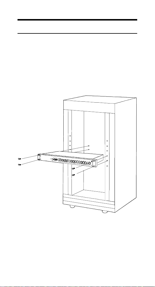
Rack Mounting
The Ethernet Hub may stand alone, or may be
mounted in a standard 19-inch equip-m ent rack.
Rack mounting produces an orderly installation
when you have a number of related network
devices. Use the six supplied screws to fasten
the supplied mounting brackets to either end of
the hub, then fasten t he hub i nt o the ra ck.
Page 4

Installing Network
Cables
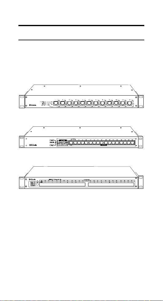
Your Ethernet Hub is denominated as an 8-port,
or 16-port, or 24-port Ethernet Hub according to
the number of its front-panel 10BaseT ports.
Additionally it has two ports whose connectors
are on the rear panel: one 10Base2 port (BNC
connector), and one 10Base5 port (AUI
connector). These two un-numbered rear-panel
ports are logically equivalent with the numbered
ports on the front panel of the E t herne t Hub.
By using a rear-panel connector of the Ethernet
Hub to connect into an existing coaxial network
cable, you can add on a star-topology subnet,
connected through the Ethernet Hub’s numbered
front-panel ports. Alternatively, you can connect
into an existing star-topology through a front
panel port of the Ethe rne t Hub, and then add on a
bus-topology subnet by connecting the subnet
bus to a rear-panel connector of the Ethernet Hub
(irrespective of any star-topology subnet that
may also be supported by the Ethernet Hub’s
front-panel ports). In either case, the unused
rear-panel connector always remains available to
connect a second coaxial cable (alternative type
of coaxial cable).
When the Ethernet Hub has no coaxial trunk
connection, then both of the rear panel
connectors remain available for coaxial stationcable connections. It is useful to keep this in
mind when you have some station equipment
whose adapters have no 10BaseT port (RJ-45
Page 5

connector), and thus can only be connected to the
hub through a coaxial cable.
Station Connections with
Twisted-Pair Cable
Connect each station to the Ethernet Hub by
means of a twisted-pair straight cable (10BaseT
cable, Category 3, 4, or 5). Plug one RJ-45
connector into a front-pa nel port of the Ethernet
Hub, and plug the other RJ-45 connector into the
station’s Ethernet adapter.
Page 6

Hub-to-Hub Connections
with Twisted-Pair Cable
Hub-to-hub connection between Model DE812TP+ Ethernet Hubs requires a 10BaseT
crossover cable. In making a hub-to-hub
connection involving a Model DE-816TP or
Model DE-824 Ethernet Hub, there is the
alternative of using a straight cable.
Internal Crossover Features
The Model DE-816TP Ethernet Hub and 24-Port
Ethernet Hub feature internal cross-over
alternatives for Port 1:
Model DE-816TP Ethernet Hub
The port numbered as Port 1 is identical with
each of the other numbered ports. But Port 1 is
specially equipped with an alternative connector,
labeled “Uplink.” The Uplink connector is
wired to the same conductors as the Port 1
connector, but with certain pin positions
interchanged to provide a cross-over, and thus
allow use of a straight cable to make a hub-tohub connection.
Keep in mind that the Uplink connector is not an
independent port. It is only an alternative
connector to Port 1, to facilitate hub-to-hub
Page 7

cabling. Port 1 is fully occupied whenever (1) a
hub-to-hub connection is made through its
Uplink connector, or (2) any kind of connection
is made directly through the Port 1 connector.
Below in this manual, the term “Uplink
selected” will mean, as to the Model DE-816TP
Ethernet Hub in question, that the subject
connection is made through the Uplink connector
Model DE-824TP Ethernet Hub
The connector numbered as Port 1 is equipped
with a switch labeled “Uplink” When the
Uplink switch is in the “ off” (tall) position, the
Port 1 connector is wired “straight” to the
supporting circuitry, and Port 1 is then identical
with each of the twenty-three other numbered
ports. When the Uplink switch is in the “ on”
(depressed) position, a pin interchange is
switched into the wiring for the Port 1 connector,
to provide a cross-over, and thus allow use of a
straight cable to make a hub-to-hub connection.
Below in this manual, the term “Uplink
selected” will mean, as to the Model DE-824TP
Ethernet Hub in question, that the subject
connection is made through Port 1 and the
Uplink switch is in its “on” (depressed) position.
Rules for Using the Uplink Feature
Uplink should never be selected for a station
cable connection. And Uplink should never be
selected for a hub-to-hub connection through a
crossover cable (because the crossover in the
connector wiring would cancel out the crossover
in the cable).
Page 8

Uplink should be selected only for making a hubto-hub connection with a straight cable. When
Uplink is selected at one end of a straight cable,
Uplink must not be selected at other end of that
cable. (If Uplink were selected at both ends of a
straight cable, then the built-in crossovers of the
two connectors would cancel one another, and
the hub-to-hub connection would fail.)
Thus the rule for making a hub-to-hub
connection with twisted-pair cable is as follows:
To make a hub-to-hub connection with a
straight cable, Uplink must be selected at
one end of the ca ble, and Uplink must not
be selected at the other end of the cable.
To make a hub-to-hub connection with a
cross-over cable, Uplink must not be
selected at either end of the cable.
Thin Coaxial Cable
Connections
To connect the Ethernet Hub to a thin coaxial
cable (10Base2 cable, also known by its wirestandard name, RG58A/U, and a variety of other
informal names), first twist a BNC T-connector
onto the rear-panel BNC connector of the
Ethernet Hub. Then twist the shell of the cable’s
connector onto either leg of the BNC T.
If the thin coaxial cable continues on to other
nodes, then twist the shell of the continuation
cable onto the remaining leg of the BNC T. If
there is no continuation (the Ethernet Hub is at
the end of the coaxial cable), then it is necessary
Page 9

to twist a 50-ohm terminator onto the remaining
open leg of the BNC T.
Sometimes several Ethernet Hubs must be colocated to support a larger array of stations than
can be handled by a single Ethernet Hub. Then it
is useful to stack the Ethernet Hubs by joining
their BNC connectors with 0.5 meter patches of
thin coaxial cable. Such stacking is just a special
case of thin coaxial cable connection as treated
above, and the terminator rule is the same: If the
stack is at the end of the incoming cable, then a
50-ohm terminator must be substituted for the
continuation cable shown in the stacking diagram
below.
Page 10

Thick Coaxial
Cable
Connections
To connect the Ethernet Hub to a thick coaxial
cable (10Base5 cable), it is necessary to have a
10Base5 Ethernet transceiver (tap) on the cable
at the Ethernet Hub’s position. Then run an AUI
cable between the transceiver’s AUI connector
and the AUI connector on the rear panel of the
Ethernet Hub.
Connecting Power
For compatibility with electric service in most
areas of the world, the Ethernet Hub’s power
supply automatically adjusts to line power in the
range 100 - 250 VAC and 50 - 60 Hz.
Per ordering option, either a Type 1 (US) or Type
2 (European) power cord is supplied with your
Ethernet Hub. See Spefications, below, for
power cord details.
Ascertain that the power switch on the rear panel
of the Ethernet Hub is in the off position. Plug
the female end of the power cord firmly into the
Page 11

receptacle on the rear panel of the Ethernet Hub.
Plug the other end of the power cord into an
electric service outlet. Turn on power to the
Ethernet Hub by switching its rear-panel power
switch to the on position.
LED Indicators
LED indicators are located on the front panel of
the Ethernet Hub.
Jabber LED
One Jabber LED for all ports. This LED flashes
red when the Ethernet Hub detects a data packet
that is defective (exceeds allowable length). This
kind of error will ordinarily be managed by the
offending Ethernet adapter itself, in which case
the Jabber LED will return to its normal off
(dark) state.
Collision LED
One Collision LED for all ports. A collision
occurs when two stations within a collision
domain attempt to transmit at the same time.
Intermittent flashing yellow of the Collision LED
is normal; the contending adapters resolve each
collision by means of a wait-then-retransmit
algorithm. Fre-quency of collisions is an
indicator of heavy traffic on the network.
Link/Rx LEDs
One Link/Rx LED for each numbered port.
Steady green (Link state) indicates that the port
has good linkage to its partner device. Flashing
Page 12

green (Receive state) indicates that the port is
receiving data from its partner device.
If the port is connected but the Link/Rx LED is
dark, check whether (1) the Ethernet Hub and the
partner device both have power, (2) the port’s
cable is firmly seated in its connectors in the
Ethernet Hub and in the partner device, (3) the
connecting cable is good and is of the correct
type, and (4) the partner device, including any
network adapter, is functioning.
Page 13

Specifications
Data transfer
rate:
Protocol: CSMA/CD
Topologies: Star, Bus
EMI Certification: DE-812TP+ and DE-824TP:
AC power: 100 - 250 V, 50 - 60 Hz
Power
consumption:
Dimensions:
Weight:
Operating
temperature:
10 Mbps
FCC Class A, VCCI I, CE A
DE-816TP:
FCC Class B, VCCI II, CE B
DE-812TP+: 18 W
DE-816TP: 18 W
DE-824TP: 20W
W x H x L, mm (including
mounting br ackets):
DE-812TP+: 483 x 44 x 125
DE-816TP: 483 x 44 x 125
DE-824TP 483 x 44 x 211
DE-812TP+: 2.0 kg
DE-816TP: 2.0 kg
DE-824TP: 3.03 kg
0° - 55° C
Humidity:
10 - 90 % non-condensing
Page 14

Power cord: Type 1 (US) or Type 2 (Europe)
per purchase order
Type 1 Type 2
Plug Rating
Cord
Rating
Length
Safety
Standard
125V, 7A
125V, 7A
1830mm ( 6f t )
UL, CSA
250V, 10A
250V, 10A
1830mm ( 6f t )
VDE
 Loading...