

Page 1

DAP-3525
Dual Band Exterior PoE Access Point
N
Quick Install Guide
B u s i n e s s C l a s s N e t w o r k i n g
®
1
Page 2

2
System Requirements
Package Contents
• D-Link DAP-3525 • Mounting Plate
• Power Adapter • Power Cord
• 4m Ethernet Cable • PoE Base
• Grounding Wire • Mounting Screws
If any of following items are missing, please contact your reseller:
Ethernet Port
Connects DAP-3525 to the network
via Ethernet cable.
1
Power LED
A solid green light indicates a proper
connection to the power supply. This
LED will blink red during boot up.
3
Reset Button
Resets the Access Point to factory
defaults.
2
LAN LED
A sold green light indicates the Ethernet
connection is good. The light will blink
during data transmission.
4
WLAN LED
A blinking green light indicates the
wireless function is working. The light
will blink fast during data transmission.
5
Important: Before connecting, you must register your Access Point online.
• Internet connectivity
• Computer with a Windows®, Macintosh®, or Linux-based operating system
• Browser with Firefox 3.6, Chrome 5.0, Safari 4.0, Internet Explorer 8.0, or later versions
• Note: your Access Point includes a one-year subscription to the CloudCommand™
online service. After one year, the service requires an annual subscription.
To properly congure your Access Point, you need:
1
3
42 5
Page 3

3
TM
Registering Your Access Point Online
New Customer: If you don’t have an existing CloudCommand™ account, create
one by following the instructions in our simple step-by-step wizard. The wizard
will guide you through the initial setup of your entire wireless network.
Step 1: Before you can use the Access Point, you must register it online.
Locate the Unit Identication Code ( UIC ) on the yellow label placed on the
underside of your Access Point.
Step 3 : Choose the appropriate registration scenario.
Step 2: Go to http://dlink.cloudcommand.com on a compatible browser
( Firefox 3.6, Chrome 5.0, Safari 4.0, Internet Explorer 8.0, or later versions ).
Existing Customer: If you already have a CloudCommand™ account, please
log in. In the left menu bar on your dashboard, click “New Access Point” and
follow the instructions.
Welcome to D-Link’s line of cloud-managed wireless Access
Points. Leverage the product’s online interface to congure,
deploy, secure and manage your entire wireless network.
Product Label
UIC: dl1153422ba3
Unit Name:
DAP -3525
FCC I D: KA2A P3520 A1
IC: 4 216A- AP352 5A1
Mod el: DAP -3525 A1
MADE I N CHINA CM
CCAX XXXXX XXXXX
MAC ID :XXXX XX000 002
CloudCommand™ Dashboard
UIC: dl115 3422b a3
Unit Name:
Page 4

4
If your network automatically assigns IP addresses ( DHCP service ), connect
the Access Point directly to the network by plugging an Ethernet cable into
the LAN port on its rear panel. Insert the cable’s other end into your existing
switch or router with Internet connectivity.
No additional configuration is required. Within a few minutes the Access
Point will self configure and become ready to use. You have the option
of later reconfiguring your Access Point to a static IP address using the
CloudCommand™ interface .
The DAP-3525 is PoE ( Power over Ethernet ) compliant. You can power it
either by using a PoE switch or the included power adapter. Once powered,
the green power LED will turn ON to indicate proper operation.
Deploying Your Access Point with Dynamic IP Addressing
Option 1:
DAP-3525
Switch or Router
Internet
Page 5
5
TM
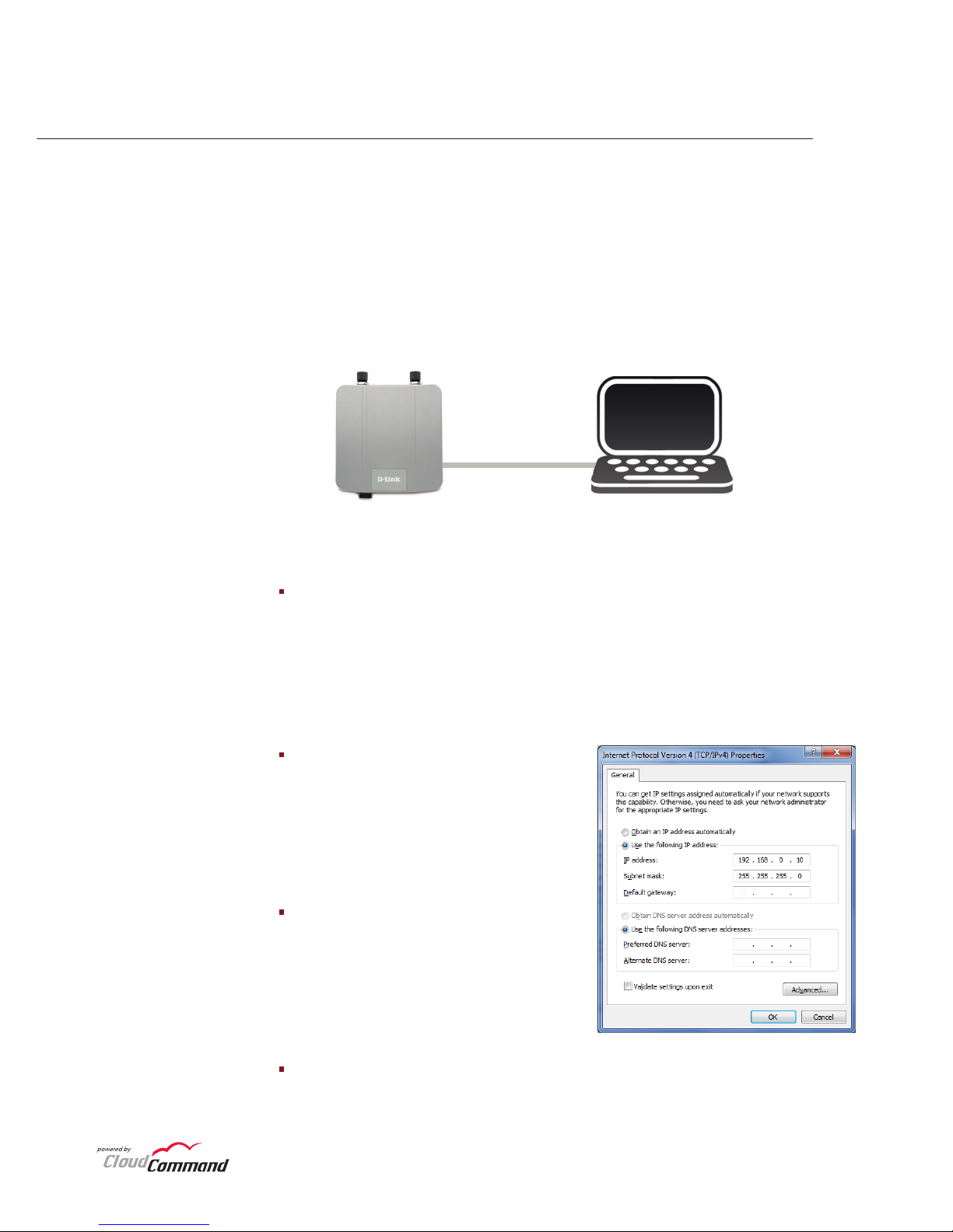
If your network does not automatically assign IP addresses ( No DHCP
service ), follow these steps to properly configure your Access Point:
Deploying Your Access Point without Dynamic IP Addressing
Option 2:
Step 1: Connect the Access Point directly to your computer using an
Ethernet cable.
Step 2: Configure the Ethernet connection of your computer as follows:
DAP-3525 PC or Mac
Configure APs
Ri g ht - c li c k on t he L oc a l Are a
Connection which represents your
network adapter and select Properties.
Highlight Internet Protocol (TCP/IP)
and click Properties.
Click Use the following IP address
and enter an IP address that is on
the same subnet as your network
or the LAN IP address on your new
DAP-3525.
Click OK twice to save your settings.
Windows® 7 - Click on Start > Control Panel > Network and Internet >
Network and Sharing Center > Change Adapter Setting.
Windows Vista® - Click on Start > Control Panel > Network and Internet >
Network and Sharing Center > Manage Network Connections.
Windows® XP - Click on Start > Control Panel > Network Connections.
Windows® 2000 - Right-click My Network Places > Properties.
Page 6
6
TM
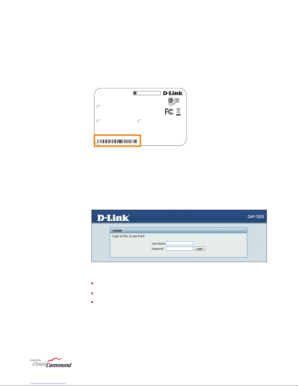
Type “admin” in the User Name eld.
Leave the Password eld blank.
Click the Login button.
Step 4: Once you enter the IP address or device name, the login screen will
appear.
Step 3: Launch a web browser and type either the IP address of the access
point (default - 192.168.0.50) or the default device name of the access point
(http://dlinkapxxxx where xxxx are the last 4 numbers of the MAC address).
The MAC Address is on the lower-left corner of the device label (highlighted
below).
DA P-3 52 5
FC C ID: K A2 AP 35 20 A1
IC : 421 6A -A P3 52 5A 1
Mo del : DA P- 35 25 A1
MAD E IN CHIN A CM
CCA XXXXX XXXXX X
MAC I D:XXX XXX00 0002
Page 7
7
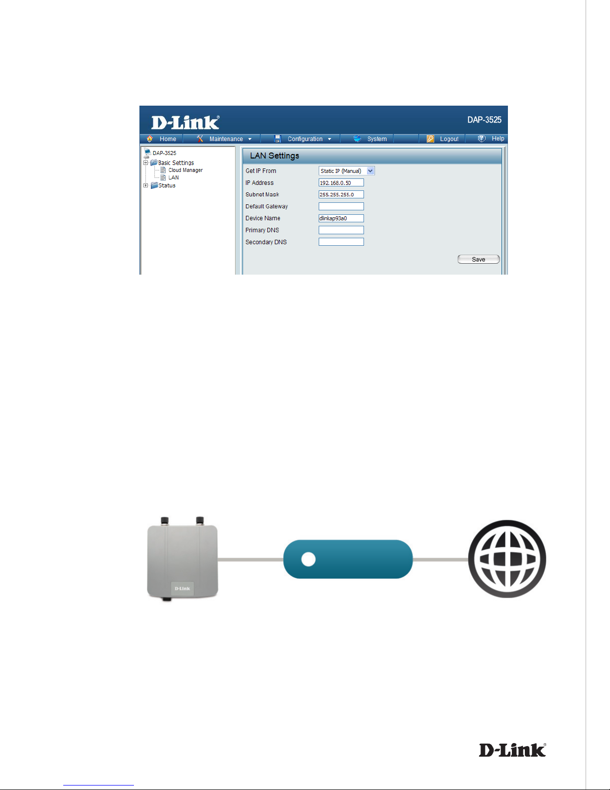
Step 6: No additional configuration is required. Within a few minutes the
Access Point will self configure and become ready to use. You have the option
of later reconfiguring your Access Point to a new static IP address using the
CloudCommand™ interface.
The DAP-3525 is PoE ( Power over Ethernet ) compliant. You can power it
either by using a PoE switch or the included power adapter. Once powered,
the green power LED will turn ON to indicate proper operation.
Step 5: Once logged in, you will be able to change the Access Point’s IP
address and DNS information to match your existing network configuration.
Step 7: Restore setting change in Step 2.
DAP-3525
Powe r over Etherne t
Switch or Router
Internet
Page 8
8
TM
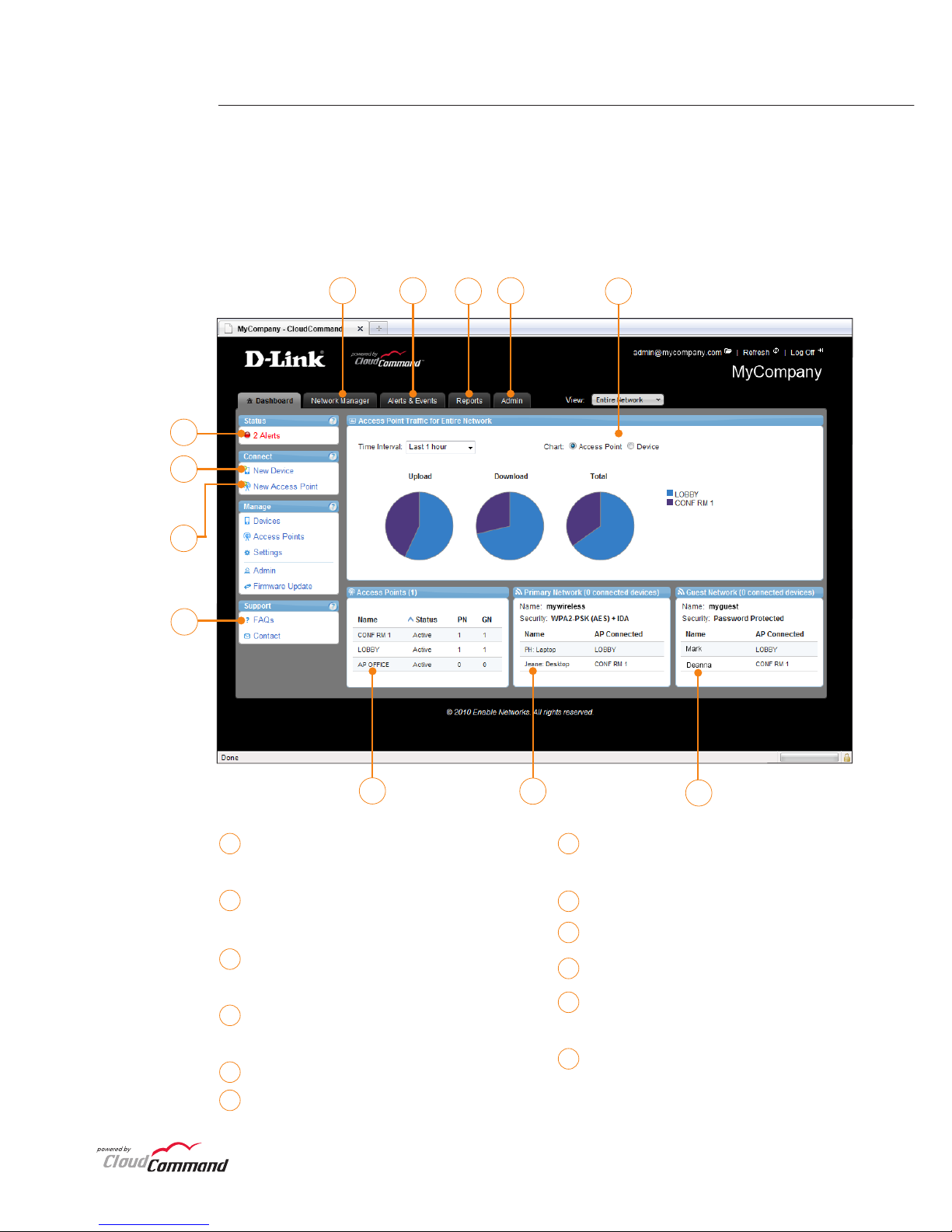
To v iew y our Clou dCo mma nd™ dash boa rd, p lea se lo g in at
http://dlink.cloudcommand.com. The dashboard is your starting point to
monitor network activity, troubleshoot problems, authorize and disconnect
individual devices, or make conguration changes to your Access Point(s).
CloudCommand™ Dashboard
10
9
1
8
7
11
12
1 7
2
8
3
9
4
10
5
11
6
12
Manage Access Points and connected
devices
View alerts and events, and set up
alert notications
Display detailed activity reports for
users and Access Points
Change congurations, Wi-Fi network
names, security, and passwords
View activity graphs
View devices connected to your
guest network
View devices connected to your
primary wireless network
View Access Points in your network
Read FAQs
Register new Access Points
Authorize a new device to connect
to your wireless network
Monitor alerts in real time
2
3
5
4
6
Page 9
9
TM
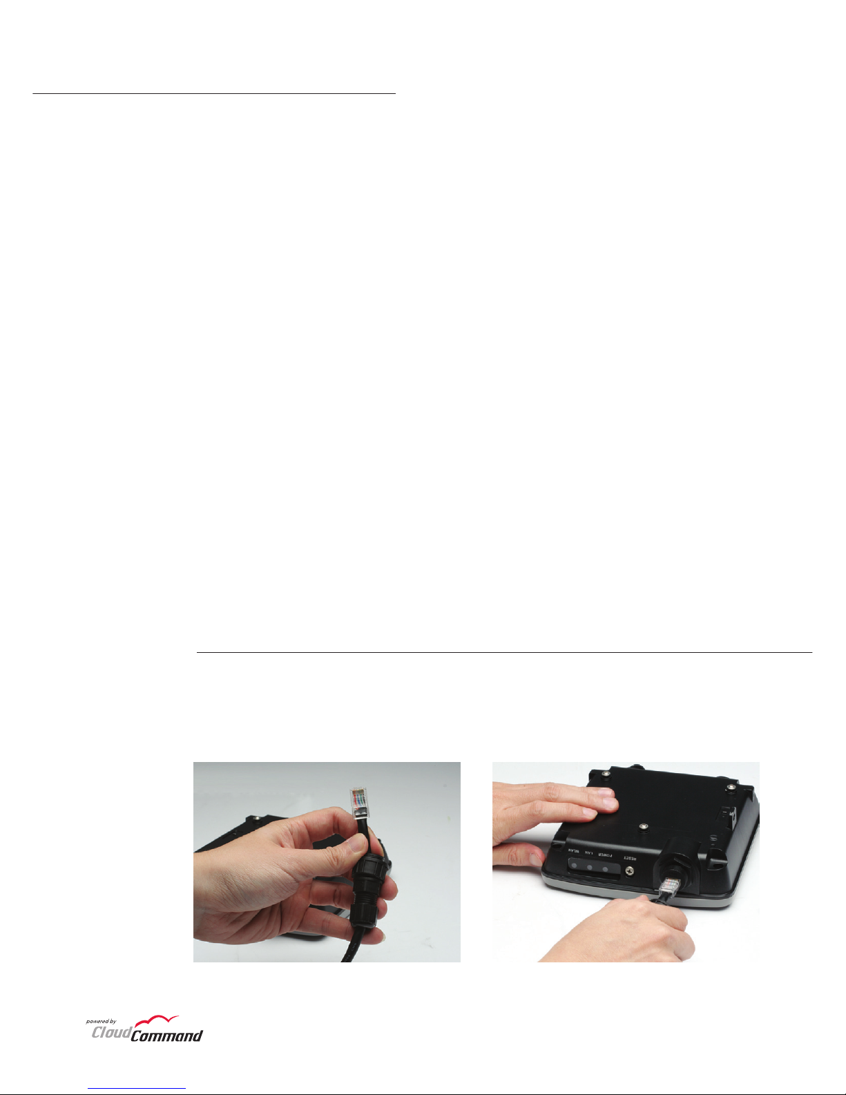
Connect the Ethernet Cable
This product should ONLY be installed by an experienced installer who is
familliar with local building and safety codes and where ever applicable, is
licensed by the appropriate authorities. Failure to do so may void the D-Link
product warranty and may expose the end user or the service provider to legal
and nancial liabilities. D-Link and its resellers or distributors are not liable for
injury, damage, or violation of regulations associated with the installation of
outdoor units or antennas.
A safety grounding system is necessary to protect your outdoor installation
from lightning strikes and the build-up of static electricity. The grounding
system must comply with the National Electrical Code and safety standards
that apply in your country. Always check with a qualied electrician if you
are in doubt as to whether your outdoor installation is properly grounded.
Note: DAP-3525 is certied to IP65 which means the device is protected
from dust and low pressure jets of water from all directions - limited ingress
permitted. It is recommended to place this device under a roof.
Installation / Mounting
Step 1: Connect the supplied Ethernet cable with the waterproof enclosure to the
Ethernet port on the DAP-3525.
Page 10
10
TM
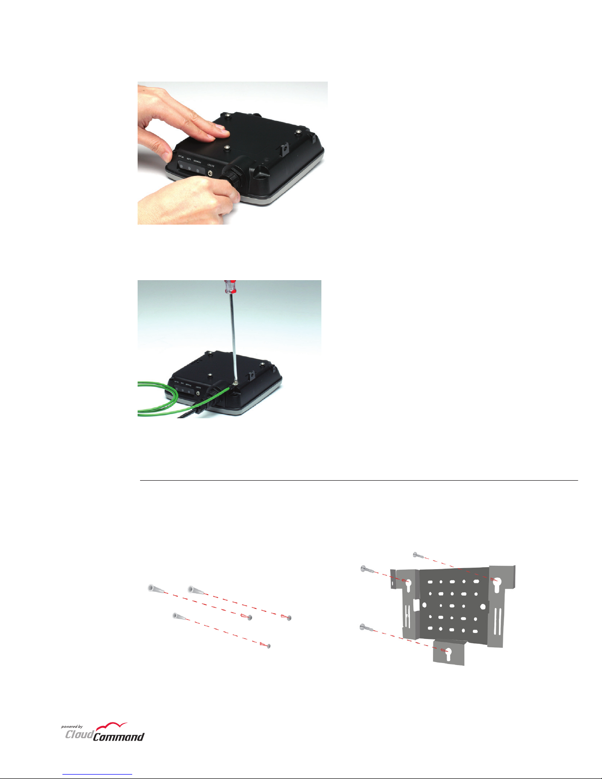
Step 2: After plugging the Ethernet cable in the port, tighten the waterproof enclosure.
Step 3: Attach the grounding cable and tighten the screw.
Attach the Mounting Plate
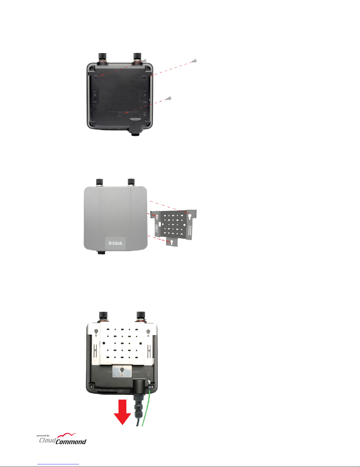
Step 1: Insert provided wall anchors in the wall where the mounting plate will
be attached. Use the provided screws to secure the mounting plate on the wall.
Page 11
11
TM
Step 2: Attach the remaining screws securely to the back of the DAP-3525.
Step 3: Attach the DAP-3525 to the mounting plate.
Step 4: Slide the DAP-3525 down into the grooves on the mounting plate
to secure it to the plate.
Page 12
12
D-Link’s website contains the latest user documentation and software
updates for D-Link products.
U.S. and Canadian customers can contact D-Link Technical Support through
our website or by phone.
United States
Telephone
877.354.6555
World Wide Web
http://support.dlink.com
Canada
Telephone
877.354.6560
World Wide Web
http://support.dlink.ca
Version 1.0
February 9, 2011
Copyright ©2011 D-Link Corporation/D-Link Systems, Inc. All rights reserved. D-Link and the D-Link
logo are registered trademarks of D-Link Corporation or its subsidiaries in the United States and
other countries. CloudCommand™ is a trademark of PowerCloud™ Systems, Inc. All rights reserved.
Other trademarks are the property of their respective owners. Product specications, size and
shape are subject to change without notice, and actual product appearance may dier from that
depicted herein.
This device complies with Part 15 of the FCC Rules. Operation is subject to the following two
conditions:
(1) This device may not cause harmful interference, and
(2) This device must accept any interference received, including interference that may cause
undesired operation.
Technical Support
 Loading...