

D-Link ANT24-CB03N, ANT24-0230, ANT24-0401, ANT24-0501, ANT24-0502 User Manual
...
DWL-AG700AP Install Guide
Version 3.00
ANT24-Series
ANT70-Series
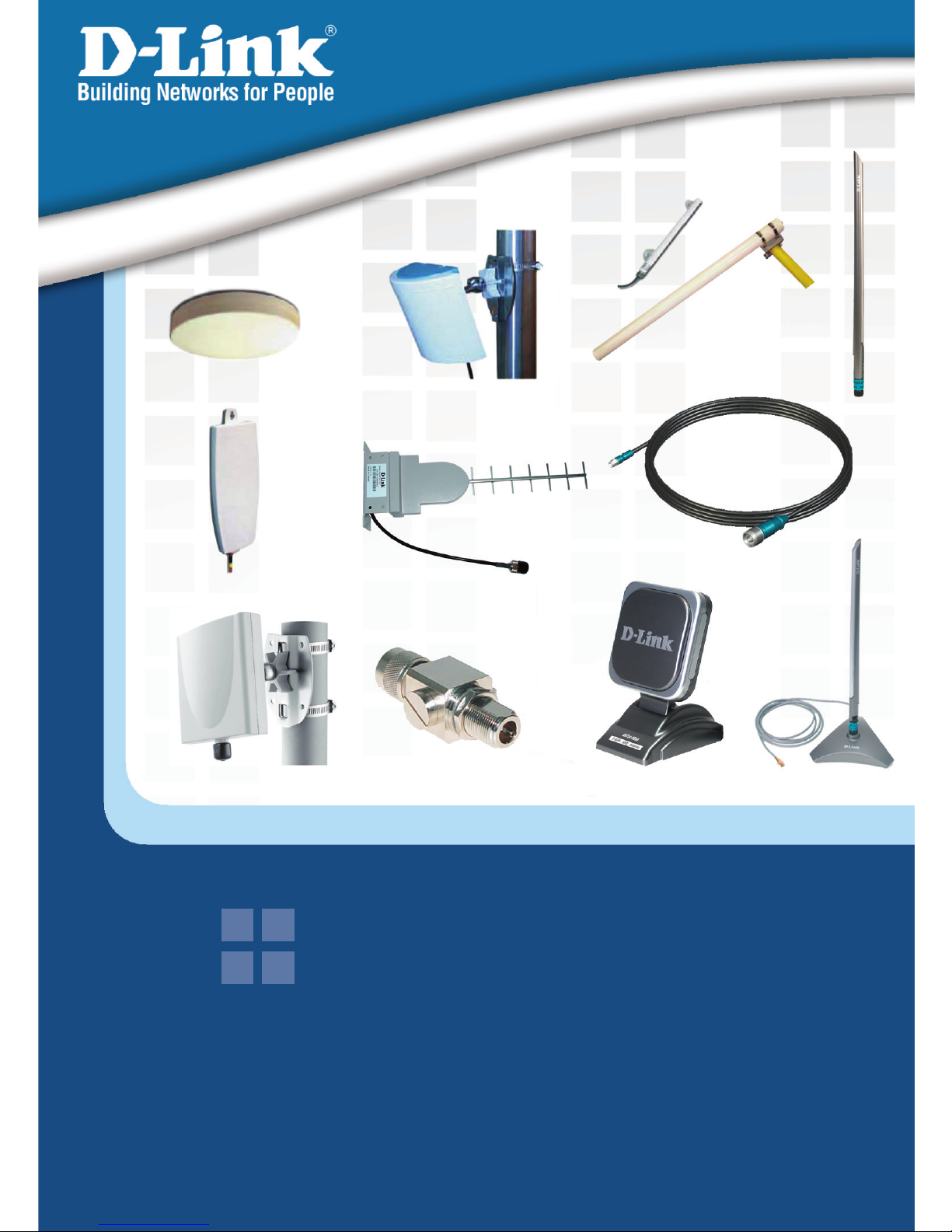
D-Link Antenna Kits
User’s Guide
2
ANT24-0700 Install GuideSystem Requirements
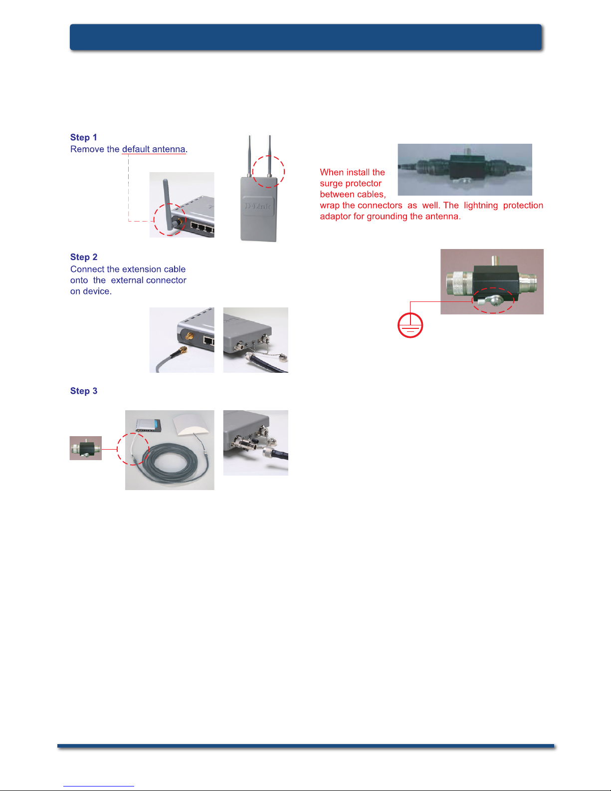
D-Link Antenna-kit Installation Guide
Installation
(If needed)
Install the surge protector. (You can install with
optional ANT24 series low loss cables)
Note:
/antenna
With Surge protector adaptor on an outdoor serial is
attached to the lightning protestion system (ground)
of the bu il ding. All devices downs tream are then
protected by the ground from lightning strikes.It can
protect your sensitive WLAN equipments from high
voltage surges caused by dischargeand transients
at the antennas. It will be integrated in the cabling
system between the antenna and the coax-cable and
must have direct ground contact.
3
System Requirements
Installation
D-Link Antenna-kit Installation Guide
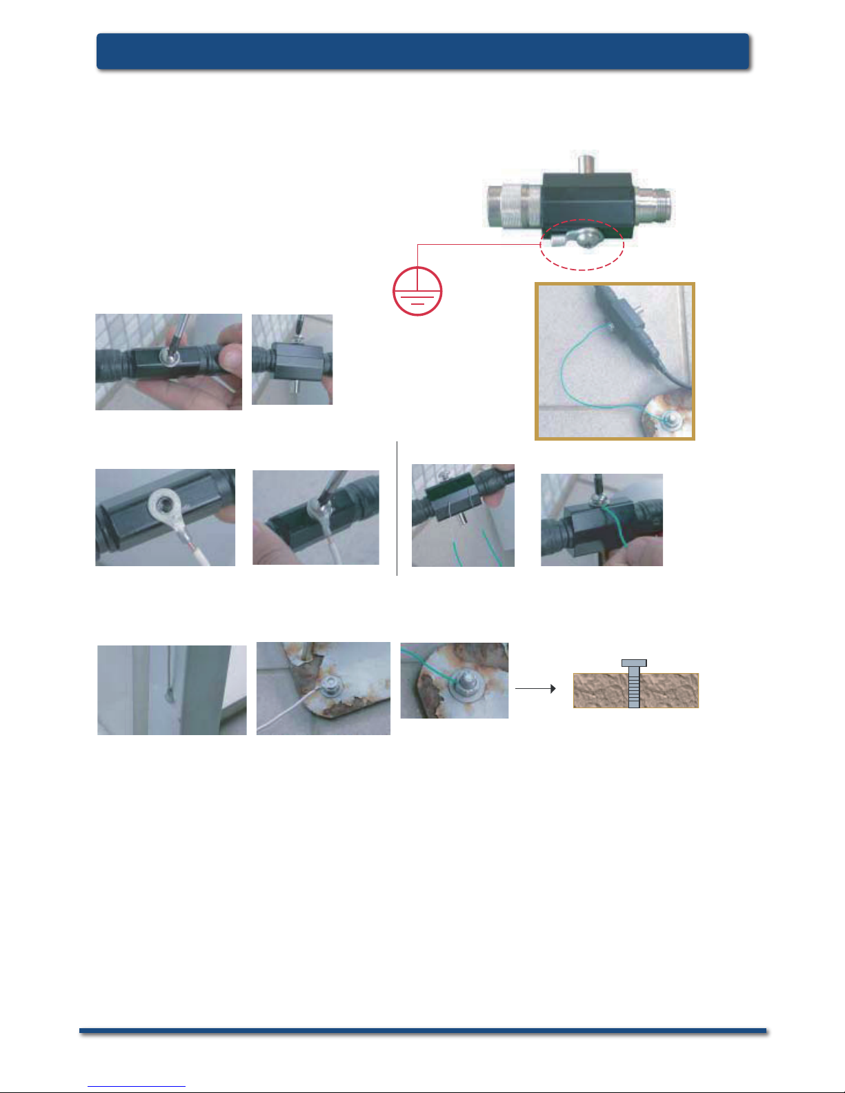
Surge protector
Installation guide
for outdoor antenna-kit
Step 1
loosen the screw from the surge protector.
Step 2
get a normal conductive copper wire with 2 sides stripped long enough to be conductive,
these wires can lead high voltage surges into the grounding.
Remark:
(1) for the ground screw you use, we suggest the longer (deeper into ground) the better performance it has.
(2) please use a copper wire with diameter at least from 2.0mm, the thicker the diameter, the higher
voltage it can sustain.
Option (1)
Option (2)
Ground
Step 3
find a conductive material nearby the antenna installation sites, connect another end of the wire
into position, there are several options:
(1) Use a long screw to stick into the ground tightly, connect another wire onto.
(2) fix or solder another end of wire onto a steel material/ bar under steel construction,
such as wall for buildings, railings or other conductive materials which set up from
the ground.
4
ANT24-0700 Install GuideSystem Requirements
ANT24-Series
Regulations
2.4GHz~2.5GHz 5.15GHz~5.35GHz5.47~5.725 5.75GHz~5.875GHz
point to multi-point
point to point
point to multi-point 36dBm 36dBm
point to point
30+6(antenna gain ) dBm
then above 30dBm, one dB output
power reduced, then 3dB antenna gain
increased
30+23(antenna gain)
then above 30dBm, one dB output power
reduced, then 3dB antenna gain increased
For outdoor use
X
FCC
23dBm
ETSI
20dBm ave.
23dBm peak.
23dBm 30dBm
X
EIRP limitaton:
EIRP = Effective,Isotropic Radiated Power
= Device Output Power + Antenna Gain - Cable Loss
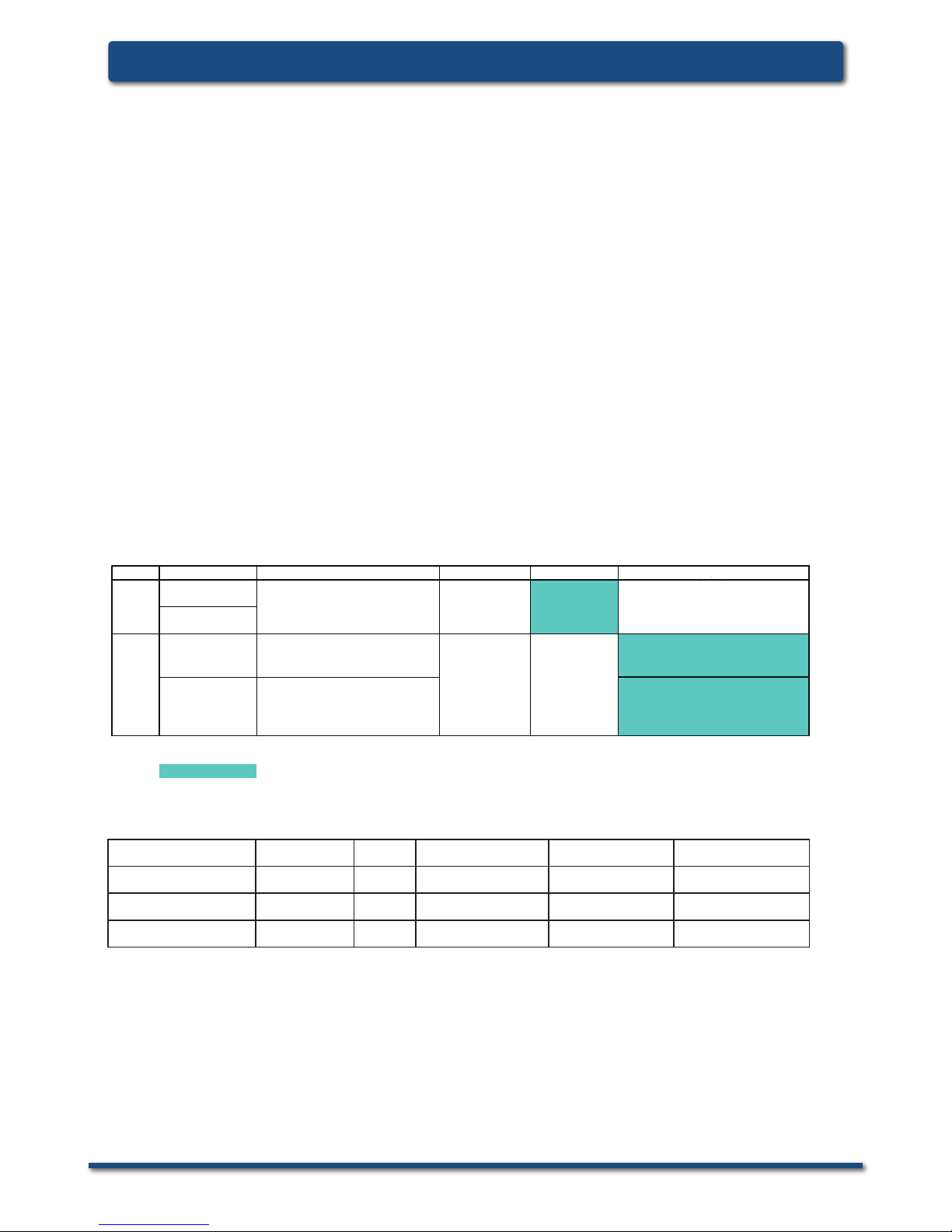
Model Cable Type Length Interface
Cable loss (dB)
@ 2.4GHz
Cable loss(dB)
@5GHz
ANT24-CB03N LMR400 3m N plug to N jack 1 1.75
ANT24-CB06N LMR400 6m N plug to N jack 1.85 2.7
ANT24-CB09N LMR400 9m N plug to N jack 2.6 3.8
Note:
1. The loss value includes two connectors ( around 0.3~0.4dB @ 2.4GHz, 0.39~0.52dB@5GHz).
2. The longer cable you use, the more attenuation it causes, therefore, the extended range might be
shorten then a normal link with default cables.
3. To comply with EU regulation, please use longer cables which can cause enough attenuation value.
4. For more detail of connectors type, please refer to the appendix page.(P.30)
Cable Loss
D-Link WLAN Antenna-Kit
Extended range differentiation for FCC/CE regulated regions
CE ETSI EN 300 328 regulated European Union (EU) regions
Based on ETSI EN 300 328, the system device and its antenna Emitted Isotropic Radiated Power
(EIRP) are limited to operate within a 20dBm gain. The range extension provided by the antenna
kit should comply with the restrictions set by the EU.
FCC regulated regions (US, Canada, etc.)
Using the same antenna-kit in FCC-regulated regions, the extended range may extend farther than
CE-regulated antennas due to a higher output power allowance (FCC limits EIRP emissions to
36dBm).
The usage of high gain antennas must be properly set to comply with EU regulations, and
additional consideration should be made to avoid potential health hazard. Consult a professional
installer for every occasion of application.
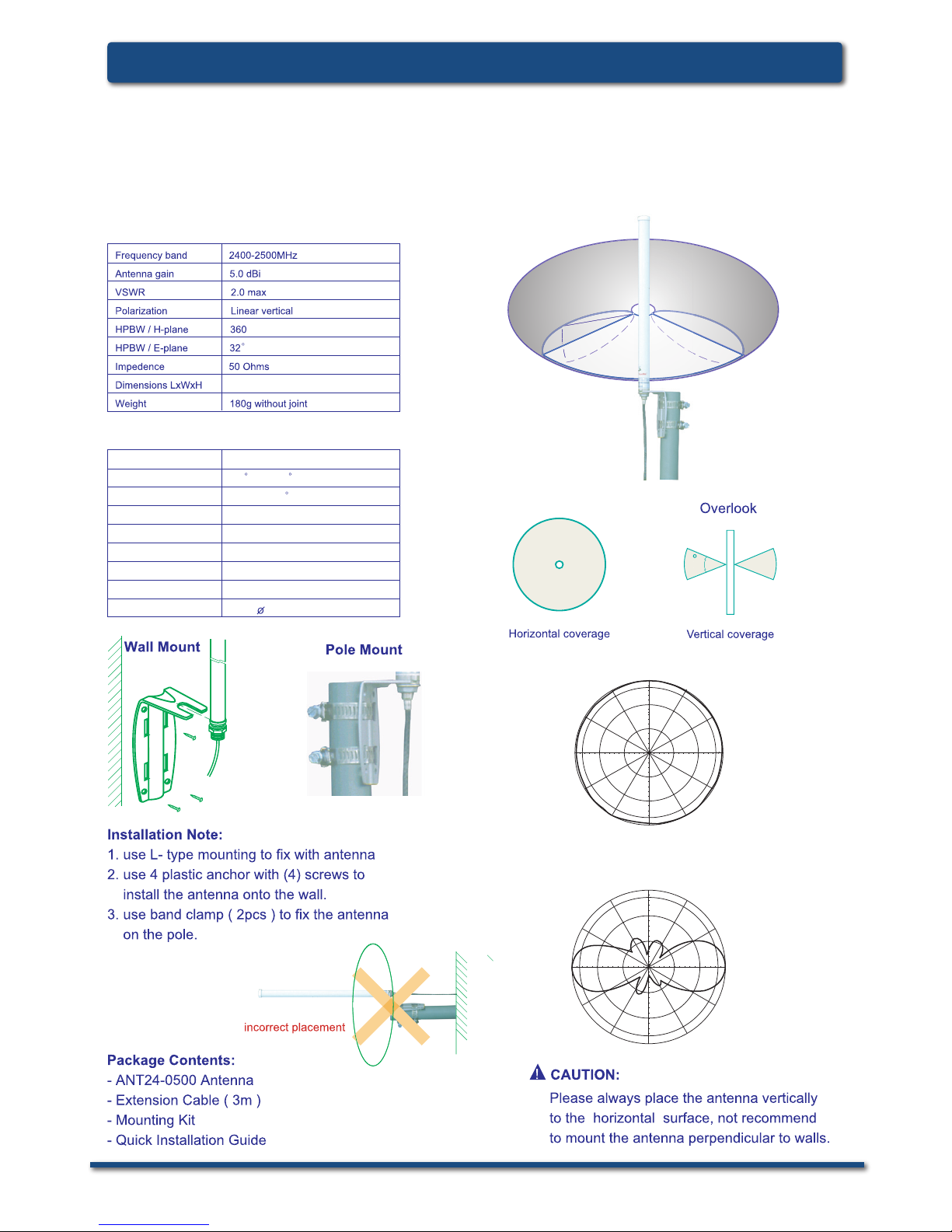
Outdoor Installations
To fully benet from D-Link’s extensive range of quality outdoor antennas, please note that they
should be installed by a professional and must comply with the Europe Union CE wireless radio
frequency output power. Cable length will affect the antenna gain dramatically.

5
System Requirements
ANT24-Series
6
ANT24-0700 Install GuideSystem Requirements
ANT24-Series
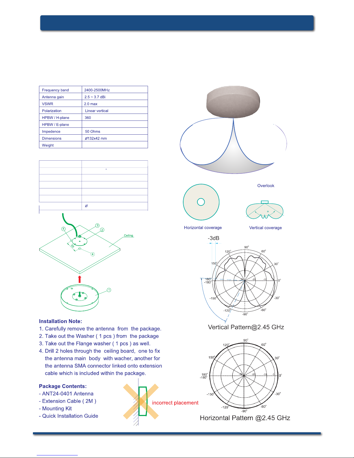
D-Link ANT24-0401
Ceiling Mount Antenna
Electrical specication
Environmental & Mechanical Characteristics
Temperature -10°C to 55°C
Humidity 100% @ 25 C
Lightning protection DC ground
Radome color white
Radome material ABS
Weight 100gw
Dimensions 132 x 42 mm
120
58°~75°
110g without joint
7
System Requirements
ANT24-Series
D-Link ANT24-0500
Indoor/Outdoor
Omni-Directional Antenna
Electrical specication
Environmental & Mechanical Characteristics
Survival wind speed 180 km/hr
Temperature -40 C to +80 C
Humidity 100% @ 25 C
Lightning protection DC ground
Radome color Gray-white
Radome material Fiberglass
Radiator material Micro striple line
Weight 0.8kgw
Dimensions 330 x 19 mm
90
o
180
o
150
o
120
o
60
o
30
o
0
o
-150
o
-90
o
-120
o
-60
o
-30
o
-3
-10
-20
-30
Version 1
H-plane Co-polarization Pattern
90
o
180
o
150
o
120
o
60
o
30
o
-150
o
-90
o
-120
o
-60
o
-30
o
-3
-10
-20
-30
V-plane Co-polarization Pattern
0
o
32
Ø19×330mm

8
ANT24-0700 Install GuideSystem Requirements
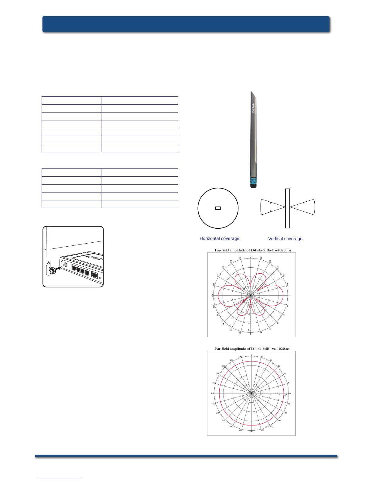
D-Link ANT24-0501
Indoor Omni-Directional Antenna
Electrical specication
Physical Properties
Package Contents
-One ANT24-0501 2.4GHz indoor 5dBi omnidirectional Antenna with 1.5M extension cable and
RP-SMA Jack connector
-One RP-SMA/ RP-TNC adaptor
-One registration card and international ofce guide
-Mounting kit includes:
-Two Crews
-Two plastic xings
-One sticker
Frequency Range 2400~2500MHz
Impedance 50Ω Normal
VSWR 1.92 Max
Return Loss -10 dB Maximum
Antenna Structure Helis antenna
Peak Gain ( w/o cable loss) 5dBi
Admitted Power 1 W
Cable loss( 1.5m) 2.1dB@2.45GHz
E-Plane 36 deg.
H-Plane 360 deg.
Cable RG-178 50Ω
Cable length 1.5 M
Cable color Gray
Connector Reverse SMA plug
Antenna Material ABS, ABS+PC
Operating Temp -20°C ~ +65°C
Storage Temp -30°C ~ +75°C
Color Antenna: Metallic gray and silver
Base: Metallic gray
0
345
330
315
300
285
270
255
240
225
210
195
180
165
150
135
120
105
90
75
60
45
30
15
-20 -10 0
dB
Far-field amplitude of D-link-7dBi-H1-1020.nsi
0
345
330
315
300
285
270
255
240
225
210
195
180
165
150
135
120
105
90
75
60
45
30
15
-20 -10 0
dB
Far-field amplitude of D-link-7dBi-v-1020.nsi
Far-field amplitude of D-link-5dBi-H-1020.nsi
Far-field amplitude of D-link-5dBi-v-1020.nsi
0
345
330
315
300
285
270
255
240
225
210
195
180
165
150
135
120
105
90
75
60
45
30
15
-20 -10 0
dB
Far-field amplitude of D-link-7dBi-v-1020.nsi
0
345
330
315
300
285
270
255
240
225
210
195
180
165
150
135
120
105
90
75
60
45
30
15
-20 -10 0
dB
Far-field amplitude of D-link-5dBi-v-1020.nsi
36°
ANT24-0700 / ANT24-0700C
0
345
330
315
300
285
270
255
240
225
210
195
180
165
150
135
120
105
90
75
60
45
30
15
-20 -10 0
dB
Far-field amplitude of D-link-7dBi-H1-1020.nsi
ANT24-0501C/ ANT24-0501
0
345
330
315
300
285
270
255
240
225
210
195
180
165
150
135
120
105
90
75
60
45
30
15
-20 -10 0
dB
Far-field amplitude of D-link-5dBi-H-1020.nsi
ANT24-Series
9
System Requirements
D-Link ANT24-0501C
Indoor Omni-Directional Antenna
Electrical specication
Physical Properties
Package Contents
-One ANT24-0501C 2.4GHz 5dBi indoor
omni-directional antenna with a RP-SMA
plug connector
-One RP SMA/ RP TNC adapter
-One registration card and company contact
guide
Frequency Range 2400~2500MHz
Impedance 50Ω Normal
VSWR 1.92 Max
Peak Gain 5dBi
Admitted Power 1 W
E-Plane 36 deg.
H-Plane 360 deg.
Connector Reverse SMA plug
Antenna Material ABS, ABS+PC
Operating Temp -20°C ~ +65°C
Storage Temp -30°C ~ +75°C
Color Antenna: Metallic gray and silver
Attach to AP/Router
36°
ANT24-Series
10
ANT24-0700 Install GuideSystem Requirements
ANT24-Series
D-Link ANT24-0502
Indoor Omni Directional Antenna
Electrical Specification
Environmental & Mechanical Characteristics
Frequency range
2400 MHz - 2500 MHz
Gain
5.0dBi
VSWR
2.0 : 1 Max
Polarization
Linear, vertical
HPBW/horizontal
360°
HPBW/vertical
40°
Downtilt
0°
Power handling
2 W (cw)
Impedance
50 Ohms
Connector
RP SMA Plug
Temperature
-10C to +55C
Humidity
95% @5ˈ˖
Radome color
Black
Radome material
ABS, UV resistant
Weight
20 g
Dimensions
ӽ13.5 x 177 mm
H-plane Co-polarization Pattern
-
24
-
21
-
18
-
15
-
12
-9
-6
-3
0
3
6
0
30
60
90
120
150
180
210
240
270
300
330
-
24
-
21
-
18
-
15
-
12
-9
-6
-3
0
3
6
2400 MHz
2450 MHz
2500 MHz
V-plane Co-polarization Pattern
-24
-21
-18
-15
-12
-9
-6
-3
0
3
6
0
30
60
90
120
150
180
210
240
270
300
330
-24
-21
-18
-15
-12
-9
-6
-3
0
3
6
2400MHz
2450MHz
2500MHz
ANT24-Series
D-Link ANT24-0502
Indoor Omni-Directional Antenna
11
System Requirements
ANT24-Series
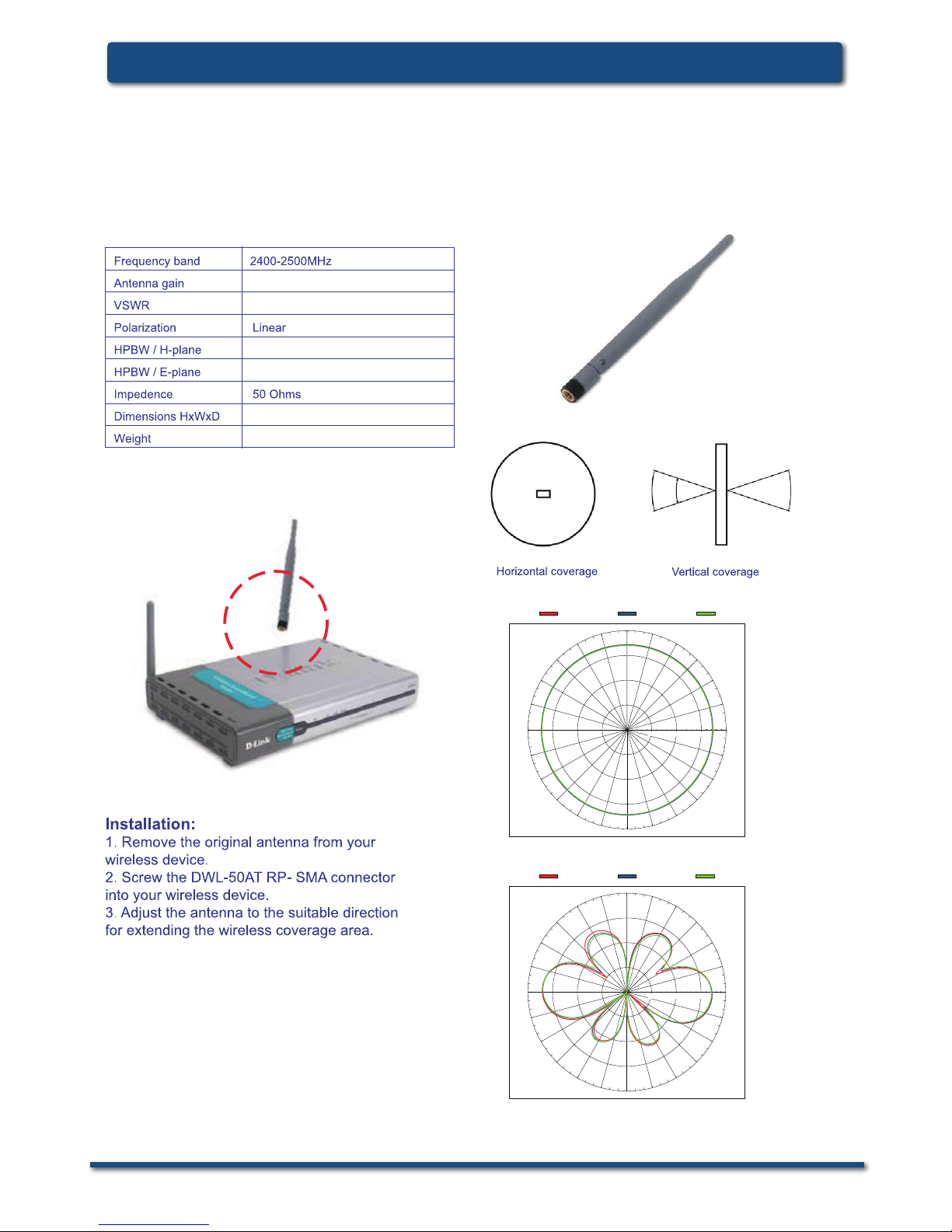
D-Link DWL-50AT
Indoor Omni-Directional Antenna
5.0dBi Typical
2.0:1 Max.
nominal
197 mm(length)
29.5gw
Electrical specication
0
345
330
315
300
285
270
255
240
225
210
195
180
165
150
135
120
105
90
75
60
45
30
15
-20 -10 0
dB
Far-field amplitude of C147-510017-A-V.nsi
2.4GHz 2.45GHz 2.5GHz
0
345
330
315
300
285
270
255
240
225
210
195
180
165
150
135
120
105
90
75
60
45
30
15
-20 -10 0
dB
Far-field amplitude of C147-510017-A-V.nsi
2.4GHz 2.45GHz 2.5GHz
0
345
330
315
300
285
270
255
240
225
210
195
180
165
150
135
120
105
90
75
60
45
30
15
-20 -10 0
dB
Far-field amplitude of C147-510017-A-H.nsi
2.4GHz 2.45GHz 2.5GHz
30°
30 degree
360°
 Loading...